US8403059B2 - External jet pump for dual gradient drilling - Google Patents
External jet pump for dual gradient drillingDownload PDFInfo
- Publication number
- US8403059B2 US8403059B2US12/778,342US77834210AUS8403059B2US 8403059 B2US8403059 B2US 8403059B2US 77834210 AUS77834210 AUS 77834210AUS 8403059 B2US8403059 B2US 8403059B2
- Authority
- US
- United States
- Prior art keywords
- conduit
- umbilical
- flexible seal
- drill pipe
- riser joint
- Prior art date
- Legal status (The legal status is an assumption and is not a legal conclusion. Google has not performed a legal analysis and makes no representation as to the accuracy of the status listed.)
- Expired - Fee Related, expires
Links
Images


Classifications
- E—FIXED CONSTRUCTIONS
- E21—EARTH OR ROCK DRILLING; MINING
- E21B—EARTH OR ROCK DRILLING; OBTAINING OIL, GAS, WATER, SOLUBLE OR MELTABLE MATERIALS OR A SLURRY OF MINERALS FROM WELLS
- E21B21/00—Methods or apparatus for flushing boreholes, e.g. by use of exhaust air from motor
- E21B21/08—Controlling or monitoring pressure or flow of drilling fluid, e.g. automatic filling of boreholes, automatic control of bottom pressure
- E21B21/082—Dual gradient systems, i.e. using two hydrostatic gradients or drilling fluid densities
- E—FIXED CONSTRUCTIONS
- E21—EARTH OR ROCK DRILLING; MINING
- E21B—EARTH OR ROCK DRILLING; OBTAINING OIL, GAS, WATER, SOLUBLE OR MELTABLE MATERIALS OR A SLURRY OF MINERALS FROM WELLS
- E21B17/00—Drilling rods or pipes; Flexible drill strings; Kellies; Drill collars; Sucker rods; Cables; Casings; Tubings
- E21B17/02—Couplings; joints
- E21B17/08—Casing joints
- E21B17/085—Riser connections
- E21B17/0853—Connections between sections of riser provided with auxiliary lines, e.g. kill and choke lines
- E—FIXED CONSTRUCTIONS
- E21—EARTH OR ROCK DRILLING; MINING
- E21B—EARTH OR ROCK DRILLING; OBTAINING OIL, GAS, WATER, SOLUBLE OR MELTABLE MATERIALS OR A SLURRY OF MINERALS FROM WELLS
- E21B21/00—Methods or apparatus for flushing boreholes, e.g. by use of exhaust air from motor
- E21B21/001—Methods or apparatus for flushing boreholes, e.g. by use of exhaust air from motor specially adapted for underwater drilling
- E—FIXED CONSTRUCTIONS
- E21—EARTH OR ROCK DRILLING; MINING
- E21B—EARTH OR ROCK DRILLING; OBTAINING OIL, GAS, WATER, SOLUBLE OR MELTABLE MATERIALS OR A SLURRY OF MINERALS FROM WELLS
- E21B33/00—Sealing or packing boreholes or wells
- E21B33/02—Surface sealing or packing
- E21B33/08—Wipers; Oil savers
- E21B33/085—Rotatable packing means, e.g. rotating blow-out preventers
- E—FIXED CONSTRUCTIONS
- E21—EARTH OR ROCK DRILLING; MINING
- E21B—EARTH OR ROCK DRILLING; OBTAINING OIL, GAS, WATER, SOLUBLE OR MELTABLE MATERIALS OR A SLURRY OF MINERALS FROM WELLS
- E21B33/00—Sealing or packing boreholes or wells
- E21B33/10—Sealing or packing boreholes or wells in the borehole
- E21B33/12—Packers; Plugs
- E21B33/126—Packers; Plugs with fluid-pressure-operated elastic cup or skirt
Definitions
- the present disclosuregenerally relates to offshore drilling services and methods, and more specifically to an apparatus and method for employing a jet pump in an underwater drilling environment.
- a wellIn order to produce fluids such as oil, gas, and water from subterranean rock formations, a well is drilled into the fluid-bearing zone. Most wells are generally drilled with a drilling rig, a drill bit, a drill pipe, and a pump for circulating fluid into and out of the hole that is being drilled.
- the drilling rigrotates and lowers the drill pipe and drill bit to penetrate the rock.
- Drilling fluidsometimes referred to as drilling mud, is pumped down the drill pipe through the drill bit to cool and lubricate the action of the drill bit as it disaggregates the rock.
- the drilling fluidremoves particles of rock, known as cuttings, generated by the rotational action of the drill bit. The cuttings become entrained in the column of drilling fluid as it returns to the surface for separation and reuse.
- jet pumpsOne method for artificially inducing lift to remove fluids from a well by using a jet pump and a power fluid.
- the use of jet pumpsis common in production operations where drilling activity has stopped. In this case, the drill pipe and drill bit have been extracted and a jet pump is lowered into the well on the end of a tubing string.
- a surface pumpdelivers high-pressure power fluid down the tubing and through the nozzle, diffuser, and diffuser of the jet pump.
- the pressure of the power fluidis converted into kinetic energy by the nozzle, which produces a high velocity jet of fluid.
- the drilling and production fluidsare drawn into the diffuser of the jet pump by the stream of high velocity power fluid flowing from the nozzle into the diffuser of the jet pump.
- the drilling and production fluidsmix with the power fluid as they pass through the diffuser.
- the diffuserconverts the high velocity mixed fluid back into a pressurized fluid.
- the pressured fluidshave sufficient energy to flow to the surface through the annulus between the production casing and the tubing that carried the jet pump into the well.
- the drill bitIn offshore drilling the drill bit is sent into rock formations beneath the sea.
- the drill bitis affixed to drill pipe that travels inside a riser string.
- the riser stringis formed of a number of riser joints.
- the use of heavy weight drilling mudcreates a high well bore pressure.
- the high well bore pressureis created when the drilling begins because of the column of drilling fluid in the drill pipe extending from the drilling platform to the seabed.
- the high well bore pressurecreates a number of problems.
- the drilling fluidmay flow outward from the drill hole and into the earth, causing a breakdown the formation.
- fluids in the reservoirmay flow into the well bore while the well is being drilled or after the well is drilled and during production.
- an apparatusmay comprise a riser joint, a conduit located outside the riser joint and configured for fluid communication with the riser joint at a first entry point and a second entry point, and a port on the conduit for receiving an umbilical.
- a sealing assemblymay be engaged in an inner wall of the riser joint.
- a flexible seal carrierhaving a first end and a second end may be configured to surround a drill pipe and to engage a running sub on the drill pipe.
- a flexible sealmay be affixed to the first end and configured to surround the drill pipe.
- a power fluidmay be injected into the conduit through the umbilical so that the riser joint and the conduit form a jet pump.
- the drill pipemay pass through the riser joint and the sealing assembly.
- a methodmay comprise providing a riser joint configured to engage a sealing assembly at a first recess in an inner wall of the riser joint, locating a conduit outside the riser joint, configuring the conduit for fluid communication with the riser joint at a first entry point above the recess and a second entry point below the recess, and providing a port on the conduit configured to receive an umbilical so that when the sealing assembly engages the first recess and a power fluid is injected into the conduit through the umbilical the riser joint and the conduit form a jet pump.
- a methodmay comprise affixing a jet pump assembly to a riser string, the jet pump assembly comprising a sealing assembly and a conduit configured for fluid communication with the jet pump assembly at a first entry point above the sealing assembly and a second entry point below the sealing assembly, passing a drill pipe through the riser string and the sealing assembly, forming a seal around the drill pipe with a flexible seal included in the sealing assembly, affixing an umbilical to a port on the conduit for receiving an umbilical, injecting a power fluid into the conduit through the umbilical, and forcing a drilling fluid up the riser string by an action of the jet pump assembly.
- a systemmay comprise a jet pump assembly affixed to a riser string and to a blowout preventer.
- the jet pump assemblymay comprise a conduit and a sealing assembly configured to accelerate a drilling fluid's return flow by a power fluid delivered by an umbilical connected to the conduit.
- FIG. 1is an illustration of a drilling system in accordance with an illustrative embodiment
- FIG. 2is an illustration of riser joint with a sealing assembly affixed to a drill pipe and slidingly engaged in a riser string in accordance with an illustrative embodiment
- FIG. 3is a detailed illustration of the riser joint with a sealing assembly affixed to the drill pipe and slidingly engaged in the riser string of FIG. 2 in accordance with an illustrative embodiment
- FIG. 4is an illustration of a riser joint with a sealing assembly moving downward in a jet pump riser joint in accordance with an illustrative embodiment
- FIG. 5is an illustration of a sealing assembly affixed to the riser joint in accordance with an illustrative embodiment
- FIG. 6is a detailed illustration of the sealing assembly affixed to the riser joint of FIG. 5 in accordance with an illustrative embodiment
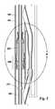
- FIG. 7is an illustration of fluid flow in a jet pump formed by the sealing assembly affixed to the jet pump riser joint and a power fluid introduced into the conduit in accordance with an illustrative embodiment
- FIG. 8is an illustration of an alternate jet pump assembly in accordance with an illustrative embodiment
- FIG. 9is a detailed illustration of the alternate jet pump assembly of FIG. 8 in accordance with an illustrative embodiment
- FIG. 10is an illustration of an alternate drilling system in accordance with an illustrative embodiment
- FIG. 11is an illustration of a flow chart for a process of providing a jet pump assembly in accordance with an illustrative embodiment.
- FIG. 12is an illustration of a flow chart for a process of employing a jet pump assembly in accordance with an illustrative embodiment.
- hydrocarbon drilling system A 100includes platform 110 , derrick 120 , and riser string 130 .
- platform 110is an offshore drilling platform.
- platformsincluding, without limitation, offshore drilling platforms, drilling ships, submersible drilling platforms configured for positioning on the ocean bed, and inshore drilling platforms.
- Offshore drilling platforms, drilling ships, and submersible drilling platformsmay be configured for positioning above and drilling into a bed of an ocean or a sea.
- Inshore drilling platformsmay be configured for positioning above and drilling into a bed of an ocean inlet, a lake or a river.
- riser stringssuch as riser string 130 may be constructed as an assembly of a number of riser joints.
- An assembly of a number of riser joints such as riser string 130may be formed by coupling one riser joint to another.
- Each riser jointmay have an upper end flange and a lower end flange.
- the upper end flange of one riser jointmay be bolted to the lower end flange of another riser joint.
- a sealmay be located between the upper end flange of one riser joint and the lower end flange of another section.
- Any number of riser jointssuch as riser joint 190 may be coupled together to form a riser string such as riser string 130 .
- a numbermeans “one or more”.
- a riser jointmay include external syntactic foam buoyancy.
- the external syntactic foam buoyancyreduces the weight in the water of the riser joint to which it is affixed, and the external syntactic foam buoyancy of each riser joint reduces the weight in the water of the riser string formed by the number of riser joints.
- Jet pump assembly 200is affixed to blowout preventer stack 160 .
- Jet pump assemblycomprises jet pump riser joint 210 , jet pump riser joint upper flange 202 , jet pump riser joint lower flange 204 , and umbilical A 150 .
- Jet pump assemblyfurther comprises sealing assembly A 230 . Sealing assembly A 230 is discussed in detail in FIGS. 2-7 below.
- Jet pump riser joint upper flange 202affixes to riser joint 190 at riser joint lower flange 201 .
- Jet pump riser joint lower flange 204affixes to blowout preventer stack flange 205 .
- Umbilical A 150is connected to pump 140 on platform 110 and to jet pump riser joint 210 .
- the drill pipesuch as drill pipe A 220 in FIG. 2 through FIG. 7 and drill pipe B 520 in FIG. 8 and FIG. 9 is approximately five and one-half to six and five-eighths inches in outside diameter and a riser joint such as riser joint 190 or jet pump riser joint 210 is approximately nineteen to nineteen and one-half inches in inside diameter to allow passage of a drill bit or other tools with an approximate eighteen and three-quarters inch diameter.
- the outside diameter of the riser jointis approximately twenty one inches.
- the drill pipe and the riser stringform only one annulus for moving fluid to the surface.
- external pipesmay run from platform 110 alongside riser string 130 in order to control a number of devices that may be attached to riser string 130 or that may be attached to a number of subsea controls for a number of devices located near the seabed 170 .
- such external pipesmay be approximately five inches in diameter.
- such external pipesmay contain a number of control lines that may be connected to the number of subsea controls.
- a subsea controlmay be a blowout preventer such as blowout preventer stack 160 in FIG. 1 .
- external flexible hosessuch as umbilical A 150 may run from platform 110 to jet pump assembly 200 .
- drilling fluid and production fluidmay be circulated by pumping drilling fluid down the drill pipe and out the drill bit and back up to the surface through an annulus between the outside of the drill pipe and the inside of the riser string.
- a power fluidmay be introduced into the annulus by a jet pump.
- a power fluidmay be sea water, drilling fluid, or oil.
- a jet pump that introduces a power fluid into the annulusmay be used to lower the hydrostatic weight, by one or two pounds per gallon, when pumping the return fluid back to surface.
- the decrease of one or two pounds per gallon of hydrostatic weight in the wellboreimproves drilling performance.
- drilling performancemay be improved because the reduction in hydrostatic weight prevents damage to a well bore caused by the hydrostatic head.
- the process of reducing hydrostatic pressure through manipulation of the pressure profile in the annulusis known as “dual gradient” drilling.
- the advantageous embodimentsrecognize and take into account that when a jet pump introduces a power fluid into the annulus to increase the return flow of the drilling mud to the surface, the overall hydrostatic weight in the wellbore is reduced.
- FIG. 2is an illustration of riser joint with a sealing assembly affixed to a drill pipe and slidingly engaged in a riser string in accordance with an illustrative embodiment.
- sealing assembly A 230may be affixed to running sub 222 of drill pipe A 220 and is shown configured for movement by sliding up and down within riser string 130 .
- FIG. 3is a detailed illustration of the riser joint with a sealing assembly affixed to the drill pipe and slidingly engaged in the riser string of FIG. 2 in accordance with an illustrative embodiment.
- sealing assembly A 230comprises flexible seal A 232 , flexible seal A carrier 234 , latch assembly 235 , static seal 248 , first lug 250 , second lug 252 , flexible seal A carrier transition 244 , and flexible seal A carrier guide 246 .
- Flexible seal A 232may be affixed to flexible seal A carrier 234 at flexible seal A carrier transition 244 .
- Sealing assembly A 230may be configured for sliding movement within riser string 130 by flexible seal A carrier 234 .
- Flexible seal A carrier 234may engage running sub 222 of drill pipe A 220 with first lug 250 and second lug 252 . Flexible seal A carrier 234 may slide within riser string 130 and may contact riser string inner wall 132 by static seal 248 . In an embodiment, latch assembly 235 may slide along riser string inner wall 132 .
- Latch assembly 235may have latch first key 236 , latch recess 238 , latch second key 240 , and latch guide 242 .
- Latch first key 236 and latch second key 240may exert outward pressure against riser string inner wall 132 while sliding within riser string inner wall 132 .
- Latch assembly 235may affix to an inner wall of a riser joint of jet pump riser joint 300 after travelling down riser string 130 to jet pump riser joint 300 . Jet pump riser joint 300 is discussed in FIGS. 4 through 7 .
- Flexible seal A carrier 234may have flexible seal A carrier opening 264 .
- Second lug 252may have vertical shear line 254 and shear pin 256 .
- Second lug 252may have second lug first position 258 , and may move to second lug second position 262 in second lug second position recess 260 .
- FIG. 4is an illustration of a riser joint with sealing assembly A 230 moving downward in a jet pump riser joint in accordance with an illustrative embodiment.
- sealing assembly A 230may be affixed to drill pipe A 220 at running sub 222 and, in an example, may have moved into jet pump riser joint 300 .
- Jet pump riser joint 300may have riser joint first recess 310 in riser joint inner wall 302 and may have riser joint second recess 312 in riser joint inner wall 302 .
- Conduit A 314may be affixed to jet pump riser joint 300 at conduit exhaust joint 316 and at conduit intake joint 318 .
- conduit A 314may be an integral part of jet pump riser joint 300 .
- conduit A 314may be affixed to jet pump riser joint by modification of a riser joint.
- a riser jointsuch as riser joint 190 in FIG. 1 is modified to be configured as a jet pump riser joint such as jet pump riser joint 300
- the riser jointmay be further configured to receive a sealing assembly such as sealing assembly A 230 .
- Conduit A 314may have conduit exhaust angle section 320 extending downward and away from jet pump riser joint 300 .
- Conduit exhaust angle section 320joins conduit exhaust section 324 .
- Conduit exhaust section 324may be approximately parallel to riser joint 300 .
- Conduit exhaust section 324joins conduit diffuser section 326 .
- Conduit diffuser section 326may have a diffuser first diameter 325 where conduit diffuser section 326 joins conduit exhaust section 324 .
- Conduit diffuser section 326joins conduit mixing section 328 .
- Conduit diffuser section 326may have conduit second diffuser diameter 327 where conduit diffuser section 326 joins conduit mixing section 328 .
- Conduit diffuser first diameter 325may be approximately twice the length of diffuser second diameter 327 .
- Conduit A 314may have conduit intake angle section 322 extending upward and away from riser joint 300 .
- Conduit intake angle section 322joins conduit entrance section 332 .
- Conduit entrance section 332joins conduit nozzle section 330 .
- Conduit nozzle section 330may have conduit nozzle first diameter 331 where conduit nozzle section 330 joins conduit entrance section 332 .
- Conduit nozzle section 330may have conduit nozzle second diameter 329 where conduit nozzle section 330 joins conduit mixing section 328 .
- Conduit nozzle first diameter 331may be greater than conduit nozzle second diameter 329 .
- Umbilical A 150extends downward from platform 110 shown in FIG. 1 .
- Umbilical A 150may be affixed to riser string 130 in FIG. 1 .
- Umbilical A 150may be connected to a pump such as pump 140 on platform 110 .
- Umbilical A 150may have umbilical u-turn section 336 , umbilical transition section 338 , umbilical insert section 340 , and umbilical nozzle 344 .
- Umbilical insert section 340enters conduit intake angle section 322 at umbilical junction 342 .
- Umbilical insert section 340may be sealingly engaged to conduit intake angle section 322 at umbilical junction 342 .
- FIG. 5is an illustration of a sealing assembly affixed in riser joint in accordance with an illustrative embodiment.
- sealing assembly A 230may have been affixed to riser joint inner wall 302 of jet pump riser joint 300 at sealing assembly A locked position 266 .
- Sealing assembly A 230may have disengaged from running sub 222 of drill pipe A 220 .
- Drill pipe A 220may have passed through sealing assembly A 230 as shown by the position of running sub 222 . Details of how sealing assembly may engage riser joint inner wall 302 and release running sub 222 of drill pipe A 220 are discussed further in the detailed view of FIG. 6 .
- FIG. 6is a detailed illustration of the sealing assembly affixed to the riser joint of FIG. 5 in accordance with an illustrative embodiment.
- sealing element A 230may be affixed to riser joint inner wall 302 by latch assembly 235 .
- sealing assembly A 230may be pulled down within jet pump riser joint 300 by running sub 222 of drill pipe A 220 .
- latch guide 242may pass riser joint first recess 310 and riser joint second recess 312 .
- Latch first key 236may engage riser joint first recess 310 and latch second key 240 may engage riser joint second recess 312 .
- Latch first key 236 and latch second key 240may be biased outward so that they may snap into the corresponding recesses. Simultaneously with latch first key 236 and latch second key 240 engaging riser joint first recess 310 and riser joint second recess 312 , downward movement of sealing element A 230 may be arrested. When downward movement of sealing element A 230 may be arrested, second lug 252 may break shear pin 256 and separate from flexible seal A carrier 234 along shear line 254 .
- latch assembly 235may be configured to break shear pin 256 when latch first key 236 and latch second key 240 engage riser joint first recess 310 and riser joint second recess 312 .
- second lug 252is shown in second lug second position 262 within second lug second position recess 260 .
- second lug 252may have a spring, that is not shown in the figures, to pull second lug 252 into second lug second position recess 260 after being sheared from flexible seal A carrier 234 .
- second lug 252may be directed to a second position after shearing from flexible seal A carrier 234 .
- second lug 252may be a compressible ring backed by a spring in a concentric cavity so that when sufficient pressure is brought to bear, second lug 252 would retreat into the concentric cavity.
- Running sub 222would be released, and a second lug second position such as second lug position 262 and a second lug second position recess such as second lug second position recess 260 would not be necessary.
- Flexible seal A 232may be slidingly engaged to drill pipe A 220 and drill pipe A 220 may slide though flexible seal A 232 .
- Flexible seal A 232is configured to allow passage of drill pipe tool joints, such as tool joint 280 in FIG. 7 , to pass through flexible seal A 232 while maintaining a seal such as drill pipe seal 362 around drill pipe A 220 .
- drill pipe tool jointssuch as tool joint 280
- Other variations in drill pipe diametermay be encountered. Such variations in drill pipe diameter may be known as upsets.
- Flexible seal A 232may be configured to maintain a seal for upsets as well as for tool joints such as tool joint 280 .
- Fluidmay travel up jet pump riser joint 300 and through sealing element A 230 only when a pressure of the fluid attempting to go up jet pump riser joint 300 through sealing assembly A 230 may be greater than the pressure of fluid above flexible seal A 232 .
- flexible seal A 232may prevent fluid from traveling up jet pump riser joint 300 when a pressure below may be higher than a pressure above drill pipe seal 362 because drill pipe seal 362 may be maintained by a pressure against drill pipe A 220 exerted by contraction of flexible seal A 232 around drill pipe A 220 .
- Such contraction of flexible seal A 232 around drill pipe A 220may be known as a positive squeeze.
- such contraction of flexible seal A 232 around drill pipe A 220may be generated by both external fluid pressure against flexible seal A 232 and also by pressure exerted by material of which flexible seal A 232 may be constructed.
- flexible seal A 232may be formed in any number of ways that may be known to persons skilled in the art.
- flexible seal A 232may be formed by pouring liquid urethane into a cylinder containing a mold and then removing the mold after the urethane has set in the desired configuration.
- flexible seal A 232may be formed from rubber, thermoplastic rubber, plastic, urethane or any other elastomeric or elastometric material possessing properties suitable for construction of sealing assembly A 230 .
- flexible seal A 232may be reinforced by metal fibers or fibers of other materials that may be included in the formation process to provide strength and durability to flexible seal A 232 .
- the metal fibers or fibers of other materialsmay extend from flexible seal A 232 in order to provide an interface with flexible seal A carrier transition 244 .
- Such metal fibers or fibers of other materialmay be affixed to flexible seal A carrier transition 244 by a number of methods that may be known to persons skilled in the art.
- flexible seal A 232may be bolted to flexible seal A carrier transition 244 .
- Sealing assembly A 230may be sealed between riser joint inner wall 302 and flexible seal A carrier 234 by static seal 248 .
- first lug 250may be affixed to flexible seal A carrier 234 and may remain in position so that when drill pipe A 220 may be withdrawn, running sub 222 of drill pipe A 220 may engage first lug 250 and pull sealing assembly A 230 up to platform 110 .
- FIG. 7is an illustration of fluid flow in a jet pump formed by the sealing assembly affixed to the jet pump riser joint and a power fluid introduced into the conduit in accordance with an illustrative embodiment.
- sealing element A 230may be affixed in sealing assembly A locked position 266 and drill pipe A 220 may move downward through sealing assembly A 230 .
- Drilling fluid flow 354illustrates the flow downward of drilling fluid from platform 110 to the drill bit.
- Drilling fluid return flow 352illustrates drilling fluid that may be brought up from the drill bit through riser string 130 and jet pump riser joint 300 .
- the pressure above drill pipe seal 362may be greater than the pressure below drill pipe seal 362 , fluid coming up from the drill bit enters conduit A 314 and may be accelerated by power fluid injected into conduit A 314 through umbilical A 150 .
- Umbilical nozzle 344 and conduit nozzle section 330may increase the velocity of power fluid flow 350 .
- power fluid flow 350may increase the velocity of drilling fluid return flow 352 .
- the advantageous embodimentsrecognize and take into account that many known jet pump configurations may be used for injection of power fluid into a drilling fluid return flow.
- a fixed sealing assemblymay be configured to allow passage of a drill bit through a sealing assembly in a jet pump assembly.
- FIG. 8 through FIG. 10illustrate such an advantageous embodiment.
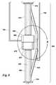
- FIG. 8is an illustration of an alternate jet pump assembly in accordance with an advantageous embodiment.
- Jet pump assembly B 400comprises riser joint upper section 410 , riser joint lower section 420 , conduit B 430 , sealing assembly B 450 , and umbilical B 152 .
- details of jet pump assembly B 400are illustrated in an advantageous embodiment in FIG. 9 .
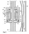
- FIG. 9is a detailed illustration of the alternate jet pump assembly of FIG. 8 in accordance with an illustrative embodiment.
- Sealing assembly B 450may be affixed to riser joint upper section 410 and to riser joint lower section.
- Sealing assembly B 450may comprise container 460 , housing 470 , and base 472 .
- Container 460may be rotatably engaged within housing 470 and base 472 .
- Container 460has upper bearing 534 and lower bearing 536 .
- Flexible seal B 510may be affixed to container 460 by flexible seal B upper seal 530 and flexible seal B lower seal 532 .
- Container 460may be sealingly engaged within housing 470 by upper seal 538 and lower seal 540 .
- Flexible seal B 510may have flexible seal B top 516 and flexible seal B bottom 514 . Fluid to control flexible seal B 510 may be inserted into cavity 511 by umbilical B 152 connected to port 556 . Fluid may flow through port 556 to first channel 552 and second channel 554 . When fluid is inserted into cavity 511 from umbilical B 152 , flexible seal B 510 compresses inwardly until flexible seal B inner surface 512 contacts drill pipe B 520 .
- flexible seal B 150may be configured to allow passage of a drill bit through a sealing assembly in a jet pump assembly when flexible seal B 150 is not compressed.
- FIG. 10is an illustration of an alternate drilling system in accordance with an illustrative embodiment.
- Drilling system B 101may have jet pump assembly B 400 connected to riser joint lower end flange 201 of riser string 130 at riser joint upper section flange 412 and to blowout preventer stack joint 205 at riser joint lower section flange 414 .
- Umbilical B 152may extend from drilling platform 110 where it may be controlled by any number of systems known to persons skilled in the art. Referring to FIG. 9 and FIG. 10 , umbilical B 152 may provide fluid to insert into cavity 511 to make flexible seal B 510 compress inwardly until flexible seal B inner surface 512 contacts drill pipe B 520 .
- FIG. 11is an illustration of a flow chart for a process of providing a jet pump assembly in accordance with an illustrative embodiment.
- Process 1100starts (operation 1102 ).
- Providing a riser joint configured to engage a sealing assembly at a first recess in an inner wall of the riser joint(operation 1104 ).
- a conduitmay be located outside the riser joint (operation 1106 ).
- the conduitmay be configured for fluid communication with the riser joint at a first entry point above the recess and a second entry point below the recess (operation 1108 ).
- a portmay be provided on the conduit configured to receive an umbilical so that when the sealing assembly engages the first recess, and a power fluid may be injected into the conduit through the umbilical (operation 1110 ).
- the flexible seal carriermay be configured to surround a drill pipe and to engage a running sub on the drill pipe (operation 1114 ). Affixing a flexible seal configured to surround the drill pipe to the first end of the flexible seal carrier (operation 1116 ).
- the flexible seal carriermay be provided with a first latch key moveably engaged to the flexible seal carrier and configured to engage the first recess (operation 1118 ).
- a second latch keymay be moveably affixed to the flexible seal carrier and configured to engage a second recess in the inner wall of the riser joint (operation 1120 ).
- a first lugmay be fixedly engaged to the flexible seal carrier and configured to removeably engage the running sub on the drill pipe (operation 1122 ).
- a second lugmay be removeably engaged to the flexible seal carrier and configured to engage the running sub on the drill pipe until released by engagement of the first latch key (operation 1124 ).
- a number of groovesare provided on the inner wall of the riser joint that guide the flexible seal carrier until the first latch key engages the first recess (operation 1126 ). Process 1100 stops (operation 1130 ).
- FIG. 12is an illustration of a flow chart for a process of employing a jet pump assembly in accordance with an illustrative embodiment.
- Process 1200starts (operation 1202 ).
- a jet pump assemblymay be affixed to a riser string, the jet pump assembly comprising a sealing assembly and a conduit configured for fluid communication with the jet pump assembly at a first entry point above the sealing assembly and a second entry point below the sealing assembly (operation 1206 ).
- a drill pipemay be passed through the riser string and the sealing element (operation 1208 ).
- a sealmay be formed around the drill pipe with a flexible seal included in the sealing element (operation 1210 ).
- An umbilicalmay be affixed to a port on the conduit for receiving an umbilical (operation 1212 ).
- a power fluidmay be injected into the conduit through the umbilical (operation 1216 ).
- a drilling fluidmay be forced up the riser string by an action of the jet pump assembly (operation 1218 ).
- the drill pipe and a drill bit affixed to the drill pipemay be moved downward through the sealing assembly (operation 1220 ).
- an apparatusmay comprises a riser joint, a conduit located outside the riser joint and configured for fluid communication with the riser joint at a first entry point and at a second entry point, and a port on the conduit receiving an umbilical.
- a sealing assemblymay be engaged in an inner wall of the riser joint.
- the sealing assemblymay further comprise a flexible seal carrier having a first end and a second end and configured to surround a drill pipe and to engage a running sub on the drill pipe.
- a flexible sealmay be affixed to the first end and configured to surround the drill pipe.
- the drill pipemay pass through the riser joint and the sealing element.
- the flexible seal carriermay further comprise a first latch key moveably engaged to the flexible seal carrier and configured to engage a first recess in an inner wall of the riser joint.
- the flexible sealmay form a seal around the drill string so that and when the power fluid is sent through the port and into the conduit a drilling fluid is forced up the riser joint and up a riser string attached to the riser joint by a jet pump.
- a second latch keymay be moveably affixed to the flexible seal carrier and may be configured to engage a second recess in the inner wall of the riser joint.
- a first lugmay be fixedly engaged to the flexible seal carrier and may be configured to removeably engage the running sub on the drill pipe.
- a second lugmay be removeably engaged to the flexible seal carrier and may be configured to engage the running sub on the drill pipe until released by an action of a latch assembly.
- a number of groovesmay be configured on the inner wall of the riser joint to guide the flexible seal carrier until the first latch key engages the first recess.
- a drill bitmay be attached to the drill pipe, wherein the sealing assembly remains affixed to the riser joint after the first latch key engages the first recess, and the drill pipe moves downward through the sealing assembly.
- the conduitmay comprise a diffuser section and a nozzle section, wherein an umbilical nozzle is positioned approximately within the nozzle section.
- a pumpmay be connected to the umbilical, and the umbilical may further comprise an umbilical u-turn section, an umbilical insert section, and an umbilical junction with the port.
- a static seal in the flexible seal carriermay engage the inner wall of the riser joint.
- a methodmay comprise providing a riser joint configured to engage a sealing assembly at a first recess in an inner wall of the riser joint, locating a conduit outside the riser joint, configuring the conduit for fluid communication with the riser joint at a first entry point above the recess and a second entry point below the recess, and providing a port on the conduit configured to receive an umbilical so that when the sealing assembly engages the first recess and a power fluid is injected into the conduit through the umbilical the riser joint and the conduit form a jet pump.
- the methodmay further comprise providing the sealing assembly with a flexible seal carrier having a first end and a second end, configuring the flexible seal carrier to surround a drill pipe and to engage an running sub on the drill pipe, and configuring a flexible seal to surround the drill pipe and to be affixed to the first end of the flexible seal carrier.
- the methodmay further comprise providing the flexible seal carrier with a first latch key moveably engaged to the flexible seal carrier and configured to engage the first recess, providing a second latch key moveably affixed to the flexible seal carrier and configured to engage a second recess in the inner wall of the riser joint, providing a first lug fixedly engaged to the flexible seal carrier and configured to removeably engage the running sub on the drill pipe, providing a second lug removeably engaged to the flexible seal carrier and configured to engage the running sub on the drill pipe until released by engagement of the first latch key, and providing a number of grooves on the inner wall of the riser joint that guide the flexible seal carrier until the first latch key engages the first recess.
- a methodmay comprise affixing a jet pump assembly to a riser string, the jet pump assembly comprising a sealing assembly and a conduit configured for fluid communication with the jet pump assembly at a first entry point above the sealing assembly and a second entry point below the sealing assembly, passing a drill pipe through the riser string and the sealing assembly, forming a seal around the drill pipe with a flexible seal included in the sealing assembly, affixing an umbilical to a port on the conduit for receiving an umbilical, injecting a power fluid into the conduit through the umbilical, and forcing a drilling fluid up the riser string by an action of the jet pump assembly.
- the methodfurther comprises moving the drill pipe and a drill bit affixed to the drill pipe downward through sealing assembly.
- a systemmay comprise a jet pump assembly affixed to a riser string and to a blowout preventer, the jet pump assembly comprising a conduit and a sealing assembly configured to accelerate a drilling fluid's return flow by a power fluid delivered by an umbilical connected to the conduit.
- the systemmay comprise a drilling platform having a pump connected to a first end of the umbilical and to the riser string, wherein the jet pump assembly comprises a conduit and a sealing assembly, wherein a drill pipe and a drill bit affixed to the drill pipe pass through the sealing assembly.
- the systemmay comprise a port on the conduit configured for receiving a second end of the umbilical.
- the sealing assemblymay comprise a flexible seal surrounding the drill pipe so that when a power fluid is sent through the port and into the conduit a drilling fluid is forced up the riser string by the jet pump assembly.
Landscapes
- Engineering & Computer Science (AREA)
- Life Sciences & Earth Sciences (AREA)
- Geology (AREA)
- Mining & Mineral Resources (AREA)
- Physics & Mathematics (AREA)
- Environmental & Geological Engineering (AREA)
- Fluid Mechanics (AREA)
- General Life Sciences & Earth Sciences (AREA)
- Geochemistry & Mineralogy (AREA)
- Mechanical Engineering (AREA)
- Jet Pumps And Other Pumps (AREA)
Abstract
Description
Claims (21)
Priority Applications (1)
| Application Number | Priority Date | Filing Date | Title |
|---|---|---|---|
| US12/778,342US8403059B2 (en) | 2010-05-12 | 2010-05-12 | External jet pump for dual gradient drilling |
Applications Claiming Priority (1)
| Application Number | Priority Date | Filing Date | Title |
|---|---|---|---|
| US12/778,342US8403059B2 (en) | 2010-05-12 | 2010-05-12 | External jet pump for dual gradient drilling |
Publications (2)
| Publication Number | Publication Date |
|---|---|
| US20110278014A1 US20110278014A1 (en) | 2011-11-17 |
| US8403059B2true US8403059B2 (en) | 2013-03-26 |
Family
ID=44910734
Family Applications (1)
| Application Number | Title | Priority Date | Filing Date |
|---|---|---|---|
| US12/778,342Expired - Fee RelatedUS8403059B2 (en) | 2010-05-12 | 2010-05-12 | External jet pump for dual gradient drilling |
Country Status (1)
| Country | Link |
|---|---|
| US (1) | US8403059B2 (en) |
Cited By (10)
| Publication number | Priority date | Publication date | Assignee | Title |
|---|---|---|---|---|
| US20100183113A1 (en)* | 2009-01-22 | 2010-07-22 | Hitachi-Ge Nuclear Energy, Ltd. | Jet pump and reactor |
| US20130067353A1 (en)* | 2002-04-30 | 2013-03-14 | James Andrew Canfield | E-Mail Interface Having an Informational Tool Tip |
| US20130140034A1 (en)* | 2011-12-02 | 2013-06-06 | General Electric Company | Seabed well influx control system |
| US20130192841A1 (en)* | 2012-01-31 | 2013-08-01 | Guy F. Feasey | Dual gradient managed pressure drilling |
| US20140178155A1 (en)* | 2012-12-21 | 2014-06-26 | Weatherford/Lamb, Inc. | Riser auxiliary line jumper system for rotating control device |
| WO2016134442A1 (en)* | 2015-02-26 | 2016-09-01 | Reitsma Donald G | Mud lift drilling system using ejector assembly in mud return line |
| US9476271B2 (en) | 2012-06-07 | 2016-10-25 | General Electric Company | Flow control system |
| US20190003289A1 (en)* | 2015-12-22 | 2019-01-03 | Shell Oil Company | Enhanced riser-based gas-lift apparatus |
| WO2019226793A1 (en)* | 2018-05-23 | 2019-11-28 | Intrinsic Energy Technology, LLC | Electric submersible hydraulic lift pump system |
| US20220010636A1 (en)* | 2019-01-09 | 2022-01-13 | Kinetic Pressure Control, Ltd. | Managed Pressure Drilling System and Method |
Families Citing this family (9)
| Publication number | Priority date | Publication date | Assignee | Title |
|---|---|---|---|---|
| CA2751179A1 (en)* | 2010-08-31 | 2012-02-29 | Michael Boyd | Rotating flow control diverter with riser pipe adapter |
| GB2509631B (en)* | 2011-10-11 | 2018-09-19 | Enhanced Drilling As | Device and method for controlling return flow from a bore hole |
| US20130168102A1 (en)* | 2011-12-28 | 2013-07-04 | Vetco Gray Inc. | Drilling riser adapter with emergency functionality |
| WO2013115651A2 (en)* | 2012-01-31 | 2013-08-08 | Agr Subsea As | Boost system and method for dual gradient drilling |
| CA2876067C (en) | 2012-06-12 | 2018-04-10 | Elite Energy Ip Holdings Ltd. | Rotating flow control diverter having dual stripper elements |
| GB2506400B (en) | 2012-09-28 | 2019-11-20 | Managed Pressure Operations | Drilling method for drilling a subterranean borehole |
| GB201503166D0 (en)* | 2015-02-25 | 2015-04-08 | Managed Pressure Operations | Riser assembly |
| US9664006B2 (en)* | 2015-09-25 | 2017-05-30 | Enhanced Drilling, A.S. | Riser isolation device having automatically operated annular seal |
| WO2018231729A1 (en) | 2017-06-12 | 2018-12-20 | Ameriforge Group Inc. | Dual gradient drilling system and method |
Citations (92)
| Publication number | Priority date | Publication date | Assignee | Title |
|---|---|---|---|---|
| US270488A (en) | 1883-01-09 | Drilling apparatus | ||
| US1831956A (en) | 1930-10-27 | 1931-11-17 | Reed Roller Bit Co | Blow out preventer |
| US2201270A (en) | 1936-04-17 | 1940-05-21 | Mcintyre John Taylor | Apparatus for allaying dust from rock drills |
| US2207199A (en) | 1937-04-26 | 1940-07-09 | Frederic W Hild | Blowout preventer |
| US2234454A (en) | 1940-05-20 | 1941-03-11 | Herman F Richter | Apparatus for drilling wells |
| US2849214A (en) | 1954-09-02 | 1958-08-26 | Gulf Research Development Co | Borehole drilling apparatus for preventing lost circulation |
| US2946565A (en) | 1953-06-16 | 1960-07-26 | Jersey Prod Res Co | Combination drilling and testing process |
| US3087558A (en) | 1962-05-23 | 1963-04-30 | Hughes Tool Co | Ball director for rock bits |
| US3208539A (en) | 1958-09-17 | 1965-09-28 | Walker Neer Mfg Co | Apparatus for drilling wells |
| US3410508A (en) | 1966-10-21 | 1968-11-12 | Goodrich Co B F | Inflatable seal |
| US3603409A (en)* | 1969-03-27 | 1971-09-07 | Regan Forge & Eng Co | Method and apparatus for balancing subsea internal and external well pressures |
| US3638721A (en)* | 1969-12-10 | 1972-02-01 | Exxon Production Research Co | Flexible connection for rotating blowout preventer |
| US3815673A (en)* | 1972-02-16 | 1974-06-11 | Exxon Production Research Co | Method and apparatus for controlling hydrostatic pressure gradient in offshore drilling operations |
| US3924696A (en) | 1971-09-08 | 1975-12-09 | Atlas Copco Ab | Method and device for dust collecting air-flushed rock drilling |
| US3948330A (en) | 1975-02-18 | 1976-04-06 | Dresser Industries, Inc. | Vacuum, vacuum-pressure, or pressure reverse circulation bit |
| US4022285A (en) | 1976-03-11 | 1977-05-10 | Frank Donald D | Drill bit with suction and method of dry drilling with liquid column |
| US4046191A (en)* | 1975-07-07 | 1977-09-06 | Exxon Production Research Company | Subsea hydraulic choke |
| US4073352A (en) | 1976-03-03 | 1978-02-14 | Occidental Oil Shale, Inc. | Raise bore drilling machine |
| US4091881A (en)* | 1977-04-11 | 1978-05-30 | Exxon Production Research Company | Artificial lift system for marine drilling riser |
| US4095656A (en) | 1976-03-03 | 1978-06-20 | Occidental Oil Shale, Inc. | Raise bore drilling |
| US4099583A (en)* | 1977-04-11 | 1978-07-11 | Exxon Production Research Company | Gas lift system for marine drilling riser |
| US4185856A (en) | 1973-04-13 | 1980-01-29 | Mcevoy Oilfield Equipment Company | Pipe joint with remotely operable latch |
| US4239087A (en) | 1977-01-28 | 1980-12-16 | Institut Francais Du Petrole | Drill bit with suction jet means |
| US4436166A (en) | 1980-07-17 | 1984-03-13 | Gill Industries, Inc. | Downhole vortex generator and method |
| US4448255A (en) | 1982-08-17 | 1984-05-15 | Shaffer Donald U | Rotary blowout preventer |
| US4534426A (en) | 1983-08-24 | 1985-08-13 | Unique Oil Tools, Inc. | Packer weighted and pressure differential method and apparatus for Big Hole drilling |
| US4567954A (en) | 1983-12-02 | 1986-02-04 | Norton Christensen, Inc. | Replaceable nozzles for insertion into a drilling bit formed by powder metallurgical techniques and a method for manufacturing the same |
| US4630691A (en) | 1983-05-19 | 1986-12-23 | Hooper David W | Annulus bypass peripheral nozzle jet pump pressure differential drilling tool and method for well drilling |
| US4687066A (en) | 1986-01-15 | 1987-08-18 | Varel Manufacturing Company | Rock bit circulation nozzle |
| US4744730A (en) | 1986-03-27 | 1988-05-17 | Roeder George K | Downhole jet pump with multiple nozzles axially aligned with venturi for producing fluid from boreholes |
| US4813495A (en)* | 1987-05-05 | 1989-03-21 | Conoco Inc. | Method and apparatus for deepwater drilling |
| US4949785A (en) | 1989-05-02 | 1990-08-21 | Beard Joseph O | Force-limiting/wear compensating annular sealing element for blowout preventers |
| US5006845A (en)* | 1989-06-13 | 1991-04-09 | Honeywell Inc. | Gas kick detector |
| US5062479A (en) | 1990-07-31 | 1991-11-05 | Masx Energy Services Group, Inc. | Stripper rubbers for drilling heads |
| US5178215A (en) | 1991-07-22 | 1993-01-12 | Folsom Metal Products, Inc. | Rotary blowout preventer adaptable for use with both kelly and overhead drive mechanisms |
| US5273108A (en) | 1992-10-21 | 1993-12-28 | Piper Oilfield Products, Inc. | Closure apparatus for blow out prevention |
| US5355967A (en) | 1992-10-30 | 1994-10-18 | Union Oil Company Of California | Underbalance jet pump drilling method |
| US5372190A (en) | 1993-06-08 | 1994-12-13 | Coleman; William P. | Down hole jet pump |
| US5456326A (en) | 1994-04-18 | 1995-10-10 | Exxon Production Research Company | Apparatus and method for installing open-ended tubular members axially into the earth |
| US5507465A (en) | 1995-04-07 | 1996-04-16 | Borle; Del | Blow-out preventer |
| US5562171A (en) | 1994-05-04 | 1996-10-08 | Baker Hughes Incorporated | Anti-balling drill bit |
| US5771984A (en) | 1995-05-19 | 1998-06-30 | Massachusetts Institute Of Technology | Continuous drilling of vertical boreholes by thermal processes: including rock spallation and fusion |
| US5775443A (en) | 1996-10-15 | 1998-07-07 | Nozzle Technology, Inc. | Jet pump drilling apparatus and method |
| US5778982A (en) | 1993-10-27 | 1998-07-14 | Baski Water Instruments, Inc. | Fixed head inflatable packer with fully reinforced inflatable element and method of fabrication |
| US5836404A (en) | 1996-04-12 | 1998-11-17 | Baker Hughes Incorporated | Drill bits with enhanced hydraulic flow characteristics |
| US5848643A (en) | 1996-12-19 | 1998-12-15 | Hydril Company | Rotating blowout preventer |
| US5921476A (en) | 1993-10-08 | 1999-07-13 | Vortexx Group Incorporated | Method and apparatus for conditioning fluid flow |
| US5992763A (en) | 1997-08-06 | 1999-11-30 | Vortexx Group Incorporated | Nozzle and method for enhancing fluid entrainment |
| US6016880A (en) | 1997-10-02 | 2000-01-25 | Abb Vetco Gray Inc. | Rotating drilling head with spaced apart seals |
| US6024172A (en) | 1997-09-25 | 2000-02-15 | Lee; Daniel | Blow-out preventer |
| US6109348A (en) | 1996-08-23 | 2000-08-29 | Caraway; Miles F. | Rotating blowout preventer |
| US6129152A (en) | 1998-04-29 | 2000-10-10 | Alpine Oil Services Inc. | Rotating bop and method |
| US6209663B1 (en) | 1998-05-18 | 2001-04-03 | David G. Hosie | Underbalanced drill string deployment valve method and apparatus |
| US6227547B1 (en) | 1998-06-05 | 2001-05-08 | Kalsi Engineering, Inc. | High pressure rotary shaft sealing mechanism |
| US6230824B1 (en)* | 1998-03-27 | 2001-05-15 | Hydril Company | Rotating subsea diverter |
| US6244336B1 (en) | 2000-03-07 | 2001-06-12 | Cooper Cameron Corporation | Double shearing rams for ram type blowout preventer |
| US6276455B1 (en) | 1997-09-25 | 2001-08-21 | Shell Offshore Inc. | Subsea gas separation system and method for offshore drilling |
| US6325159B1 (en)* | 1998-03-27 | 2001-12-04 | Hydril Company | Offshore drilling system |
| US6328107B1 (en)* | 1999-09-17 | 2001-12-11 | Exxonmobil Upstream Research Company | Method for installing a well casing into a subsea well being drilled with a dual density drilling system |
| US20020104660A1 (en) | 2000-12-05 | 2002-08-08 | Baker Hughes, Incorporated | Sea-floor pressure head assembly |
| US6457529B2 (en)* | 2000-02-17 | 2002-10-01 | Abb Vetco Gray Inc. | Apparatus and method for returning drilling fluid from a subsea wellbore |
| US6470975B1 (en) | 1999-03-02 | 2002-10-29 | Weatherford/Lamb, Inc. | Internal riser rotating control head |
| US20020170749A1 (en) | 2001-04-18 | 2002-11-21 | Hoyer Carel W. J. | Method of dynamically controlling bottom hole circulation pressure in a wellbore |
| US6497290B1 (en) | 1995-07-25 | 2002-12-24 | John G. Misselbrook | Method and apparatus using coiled-in-coiled tubing |
| US6520253B2 (en) | 2000-05-10 | 2003-02-18 | Abb Vetco Gray Inc. | Rotating drilling head system with static seals |
| EP1288434A1 (en) | 2001-09-04 | 2003-03-05 | Hughes UBHD Tool Company LLC | Downhole drilling assembly with independent jet pump |
| US6530437B2 (en)* | 2000-06-08 | 2003-03-11 | Maurer Technology Incorporated | Multi-gradient drilling method and system |
| US6536540B2 (en)* | 2001-02-15 | 2003-03-25 | De Boer Luc | Method and apparatus for varying the density of drilling fluids in deep water oil drilling applications |
| US6554016B2 (en) | 2000-12-12 | 2003-04-29 | Northland Energy Corporation | Rotating blowout preventer with independent cooling circuits and thrust bearing |
| US6571873B2 (en)* | 2001-02-23 | 2003-06-03 | Exxonmobil Upstream Research Company | Method for controlling bottom-hole pressure during dual-gradient drilling |
| US6626245B1 (en) | 2000-03-29 | 2003-09-30 | L Murray Dallas | Blowout preventer protector and method of using same |
| US6745857B2 (en)* | 2001-09-21 | 2004-06-08 | National Oilwell Norway As | Method of drilling sub-sea oil and gas production wells |
| US6764110B2 (en) | 2001-05-04 | 2004-07-20 | Russell Larry R | Remotely pretensioned threaded tubular connections |
| US6769498B2 (en) | 2002-07-22 | 2004-08-03 | Sunstone Corporation | Method and apparatus for inducing under balanced drilling conditions using an injection tool attached to a concentric string of casing |
| US6802379B2 (en)* | 2001-02-23 | 2004-10-12 | Exxonmobil Upstream Research Company | Liquid lift method for drilling risers |
| US6837313B2 (en)* | 2002-01-08 | 2005-01-04 | Weatherford/Lamb, Inc. | Apparatus and method to reduce fluid pressure in a wellbore |
| US6843331B2 (en)* | 2001-02-15 | 2005-01-18 | De Boer Luc | Method and apparatus for varying the density of drilling fluids in deep water oil drilling applications |
| US6899188B2 (en) | 2003-03-26 | 2005-05-31 | Sunstone Corporation | Down hole drilling assembly with concentric casing actuated jet pump |
| US6966392B2 (en)* | 2001-02-15 | 2005-11-22 | Deboer Luc | Method for varying the density of drilling fluids in deep water oil and gas drilling applications |
| US7032691B2 (en)* | 2003-10-30 | 2006-04-25 | Stena Drilling Ltd. | Underbalanced well drilling and production |
| US7090036B2 (en)* | 2001-02-15 | 2006-08-15 | Deboer Luc | System for drilling oil and gas wells by varying the density of drilling fluids to achieve near-balanced, underbalanced, or overbalanced drilling conditions |
| US7165610B2 (en)* | 2003-09-24 | 2007-01-23 | Cameron International Corporation | Removable seal |
| US7270185B2 (en)* | 1998-07-15 | 2007-09-18 | Baker Hughes Incorporated | Drilling system and method for controlling equivalent circulating density during drilling of wellbores |
| US7380590B2 (en) | 2004-08-19 | 2008-06-03 | Sunstone Corporation | Rotating pressure control head |
| US20080296062A1 (en)* | 2007-06-01 | 2008-12-04 | Horton Technologies, Llc | Dual Density Mud Return System |
| US20090236144A1 (en)* | 2006-02-09 | 2009-09-24 | Todd Richard J | Managed pressure and/or temperature drilling system and method |
| US20100006297A1 (en)* | 2006-07-14 | 2010-01-14 | Agr Subsea As | Pipe string device for conveying a fluid from a well head to a vessel |
| US7699109B2 (en)* | 2006-11-06 | 2010-04-20 | Smith International | Rotating control device apparatus and method |
| US7699110B2 (en)* | 2006-07-19 | 2010-04-20 | Baker Hughes Incorporated | Flow diverter tool assembly and methods of using same |
| US20100175882A1 (en)* | 2009-01-15 | 2010-07-15 | Weatherford/Lamb, Inc. | Subsea Internal Riser Rotating Control Device System and Method |
| US7762357B2 (en)* | 2001-02-15 | 2010-07-27 | Dual Gradient Systems, Llc | Dual gradient drilling method and apparatus with an adjustable centrifuge |
| US8033335B2 (en)* | 2006-11-07 | 2011-10-11 | Halliburton Energy Services, Inc. | Offshore universal riser system |
- 2010
- 2010-05-12USUS12/778,342patent/US8403059B2/ennot_activeExpired - Fee Related
Patent Citations (97)
| Publication number | Priority date | Publication date | Assignee | Title |
|---|---|---|---|---|
| US270488A (en) | 1883-01-09 | Drilling apparatus | ||
| US1831956A (en) | 1930-10-27 | 1931-11-17 | Reed Roller Bit Co | Blow out preventer |
| US2201270A (en) | 1936-04-17 | 1940-05-21 | Mcintyre John Taylor | Apparatus for allaying dust from rock drills |
| US2207199A (en) | 1937-04-26 | 1940-07-09 | Frederic W Hild | Blowout preventer |
| US2234454A (en) | 1940-05-20 | 1941-03-11 | Herman F Richter | Apparatus for drilling wells |
| US2946565A (en) | 1953-06-16 | 1960-07-26 | Jersey Prod Res Co | Combination drilling and testing process |
| US2849214A (en) | 1954-09-02 | 1958-08-26 | Gulf Research Development Co | Borehole drilling apparatus for preventing lost circulation |
| US3208539A (en) | 1958-09-17 | 1965-09-28 | Walker Neer Mfg Co | Apparatus for drilling wells |
| US3087558A (en) | 1962-05-23 | 1963-04-30 | Hughes Tool Co | Ball director for rock bits |
| US3410508A (en) | 1966-10-21 | 1968-11-12 | Goodrich Co B F | Inflatable seal |
| US3603409A (en)* | 1969-03-27 | 1971-09-07 | Regan Forge & Eng Co | Method and apparatus for balancing subsea internal and external well pressures |
| US3638721A (en)* | 1969-12-10 | 1972-02-01 | Exxon Production Research Co | Flexible connection for rotating blowout preventer |
| US3924696A (en) | 1971-09-08 | 1975-12-09 | Atlas Copco Ab | Method and device for dust collecting air-flushed rock drilling |
| US3815673A (en)* | 1972-02-16 | 1974-06-11 | Exxon Production Research Co | Method and apparatus for controlling hydrostatic pressure gradient in offshore drilling operations |
| US4185856A (en) | 1973-04-13 | 1980-01-29 | Mcevoy Oilfield Equipment Company | Pipe joint with remotely operable latch |
| US3948330A (en) | 1975-02-18 | 1976-04-06 | Dresser Industries, Inc. | Vacuum, vacuum-pressure, or pressure reverse circulation bit |
| US4046191A (en)* | 1975-07-07 | 1977-09-06 | Exxon Production Research Company | Subsea hydraulic choke |
| US4073352A (en) | 1976-03-03 | 1978-02-14 | Occidental Oil Shale, Inc. | Raise bore drilling machine |
| US4095656A (en) | 1976-03-03 | 1978-06-20 | Occidental Oil Shale, Inc. | Raise bore drilling |
| US4022285A (en) | 1976-03-11 | 1977-05-10 | Frank Donald D | Drill bit with suction and method of dry drilling with liquid column |
| US4239087A (en) | 1977-01-28 | 1980-12-16 | Institut Francais Du Petrole | Drill bit with suction jet means |
| US4091881A (en)* | 1977-04-11 | 1978-05-30 | Exxon Production Research Company | Artificial lift system for marine drilling riser |
| US4099583A (en)* | 1977-04-11 | 1978-07-11 | Exxon Production Research Company | Gas lift system for marine drilling riser |
| US4436166A (en) | 1980-07-17 | 1984-03-13 | Gill Industries, Inc. | Downhole vortex generator and method |
| US4448255A (en) | 1982-08-17 | 1984-05-15 | Shaffer Donald U | Rotary blowout preventer |
| US4630691A (en) | 1983-05-19 | 1986-12-23 | Hooper David W | Annulus bypass peripheral nozzle jet pump pressure differential drilling tool and method for well drilling |
| US4534426A (en) | 1983-08-24 | 1985-08-13 | Unique Oil Tools, Inc. | Packer weighted and pressure differential method and apparatus for Big Hole drilling |
| US4567954A (en) | 1983-12-02 | 1986-02-04 | Norton Christensen, Inc. | Replaceable nozzles for insertion into a drilling bit formed by powder metallurgical techniques and a method for manufacturing the same |
| US4687066A (en) | 1986-01-15 | 1987-08-18 | Varel Manufacturing Company | Rock bit circulation nozzle |
| US4744730A (en) | 1986-03-27 | 1988-05-17 | Roeder George K | Downhole jet pump with multiple nozzles axially aligned with venturi for producing fluid from boreholes |
| US4813495A (en)* | 1987-05-05 | 1989-03-21 | Conoco Inc. | Method and apparatus for deepwater drilling |
| US4949785A (en) | 1989-05-02 | 1990-08-21 | Beard Joseph O | Force-limiting/wear compensating annular sealing element for blowout preventers |
| US5006845A (en)* | 1989-06-13 | 1991-04-09 | Honeywell Inc. | Gas kick detector |
| US5062479A (en) | 1990-07-31 | 1991-11-05 | Masx Energy Services Group, Inc. | Stripper rubbers for drilling heads |
| US5178215A (en) | 1991-07-22 | 1993-01-12 | Folsom Metal Products, Inc. | Rotary blowout preventer adaptable for use with both kelly and overhead drive mechanisms |
| US5279365A (en) | 1991-07-22 | 1994-01-18 | Folsom Metal Products, Inc. | Rotary blowout preventer adaptable for use with both kelly and overhead drive mechanisms |
| US5273108A (en) | 1992-10-21 | 1993-12-28 | Piper Oilfield Products, Inc. | Closure apparatus for blow out prevention |
| US5355967A (en) | 1992-10-30 | 1994-10-18 | Union Oil Company Of California | Underbalance jet pump drilling method |
| US5372190A (en) | 1993-06-08 | 1994-12-13 | Coleman; William P. | Down hole jet pump |
| US5921476A (en) | 1993-10-08 | 1999-07-13 | Vortexx Group Incorporated | Method and apparatus for conditioning fluid flow |
| US5778982A (en) | 1993-10-27 | 1998-07-14 | Baski Water Instruments, Inc. | Fixed head inflatable packer with fully reinforced inflatable element and method of fabrication |
| US5456326A (en) | 1994-04-18 | 1995-10-10 | Exxon Production Research Company | Apparatus and method for installing open-ended tubular members axially into the earth |
| US5562171A (en) | 1994-05-04 | 1996-10-08 | Baker Hughes Incorporated | Anti-balling drill bit |
| US5507465A (en) | 1995-04-07 | 1996-04-16 | Borle; Del | Blow-out preventer |
| US5771984A (en) | 1995-05-19 | 1998-06-30 | Massachusetts Institute Of Technology | Continuous drilling of vertical boreholes by thermal processes: including rock spallation and fusion |
| US6497290B1 (en) | 1995-07-25 | 2002-12-24 | John G. Misselbrook | Method and apparatus using coiled-in-coiled tubing |
| US5836404A (en) | 1996-04-12 | 1998-11-17 | Baker Hughes Incorporated | Drill bits with enhanced hydraulic flow characteristics |
| US6109348A (en) | 1996-08-23 | 2000-08-29 | Caraway; Miles F. | Rotating blowout preventer |
| US5775443A (en) | 1996-10-15 | 1998-07-07 | Nozzle Technology, Inc. | Jet pump drilling apparatus and method |
| US5848643A (en) | 1996-12-19 | 1998-12-15 | Hydril Company | Rotating blowout preventer |
| US5992763A (en) | 1997-08-06 | 1999-11-30 | Vortexx Group Incorporated | Nozzle and method for enhancing fluid entrainment |
| US6024172A (en) | 1997-09-25 | 2000-02-15 | Lee; Daniel | Blow-out preventer |
| US6276455B1 (en) | 1997-09-25 | 2001-08-21 | Shell Offshore Inc. | Subsea gas separation system and method for offshore drilling |
| US6016880A (en) | 1997-10-02 | 2000-01-25 | Abb Vetco Gray Inc. | Rotating drilling head with spaced apart seals |
| US6230824B1 (en)* | 1998-03-27 | 2001-05-15 | Hydril Company | Rotating subsea diverter |
| US6325159B1 (en)* | 1998-03-27 | 2001-12-04 | Hydril Company | Offshore drilling system |
| US6129152A (en) | 1998-04-29 | 2000-10-10 | Alpine Oil Services Inc. | Rotating bop and method |
| US6209663B1 (en) | 1998-05-18 | 2001-04-03 | David G. Hosie | Underbalanced drill string deployment valve method and apparatus |
| US6227547B1 (en) | 1998-06-05 | 2001-05-08 | Kalsi Engineering, Inc. | High pressure rotary shaft sealing mechanism |
| US7270185B2 (en)* | 1998-07-15 | 2007-09-18 | Baker Hughes Incorporated | Drilling system and method for controlling equivalent circulating density during drilling of wellbores |
| US6470975B1 (en) | 1999-03-02 | 2002-10-29 | Weatherford/Lamb, Inc. | Internal riser rotating control head |
| US6328107B1 (en)* | 1999-09-17 | 2001-12-11 | Exxonmobil Upstream Research Company | Method for installing a well casing into a subsea well being drilled with a dual density drilling system |
| US6457529B2 (en)* | 2000-02-17 | 2002-10-01 | Abb Vetco Gray Inc. | Apparatus and method for returning drilling fluid from a subsea wellbore |
| US6244336B1 (en) | 2000-03-07 | 2001-06-12 | Cooper Cameron Corporation | Double shearing rams for ram type blowout preventer |
| US6626245B1 (en) | 2000-03-29 | 2003-09-30 | L Murray Dallas | Blowout preventer protector and method of using same |
| US6520253B2 (en) | 2000-05-10 | 2003-02-18 | Abb Vetco Gray Inc. | Rotating drilling head system with static seals |
| US6530437B2 (en)* | 2000-06-08 | 2003-03-11 | Maurer Technology Incorporated | Multi-gradient drilling method and system |
| US20020104660A1 (en) | 2000-12-05 | 2002-08-08 | Baker Hughes, Incorporated | Sea-floor pressure head assembly |
| US6554016B2 (en) | 2000-12-12 | 2003-04-29 | Northland Energy Corporation | Rotating blowout preventer with independent cooling circuits and thrust bearing |
| US7762357B2 (en)* | 2001-02-15 | 2010-07-27 | Dual Gradient Systems, Llc | Dual gradient drilling method and apparatus with an adjustable centrifuge |
| US6536540B2 (en)* | 2001-02-15 | 2003-03-25 | De Boer Luc | Method and apparatus for varying the density of drilling fluids in deep water oil drilling applications |
| US7992655B2 (en)* | 2001-02-15 | 2011-08-09 | Dual Gradient Systems, Llc | Dual gradient drilling method and apparatus with multiple concentric drill tubes and blowout preventers |
| US7090036B2 (en)* | 2001-02-15 | 2006-08-15 | Deboer Luc | System for drilling oil and gas wells by varying the density of drilling fluids to achieve near-balanced, underbalanced, or overbalanced drilling conditions |
| US7992654B2 (en)* | 2001-02-15 | 2011-08-09 | Dual Gradient Systems, Llc | Dual gradient drilling method and apparatus with an adjustable centrifuge |
| US6966392B2 (en)* | 2001-02-15 | 2005-11-22 | Deboer Luc | Method for varying the density of drilling fluids in deep water oil and gas drilling applications |
| US6843331B2 (en)* | 2001-02-15 | 2005-01-18 | De Boer Luc | Method and apparatus for varying the density of drilling fluids in deep water oil drilling applications |
| US6571873B2 (en)* | 2001-02-23 | 2003-06-03 | Exxonmobil Upstream Research Company | Method for controlling bottom-hole pressure during dual-gradient drilling |
| US6802379B2 (en)* | 2001-02-23 | 2004-10-12 | Exxonmobil Upstream Research Company | Liquid lift method for drilling risers |
| US20020170749A1 (en) | 2001-04-18 | 2002-11-21 | Hoyer Carel W. J. | Method of dynamically controlling bottom hole circulation pressure in a wellbore |
| US6764110B2 (en) | 2001-05-04 | 2004-07-20 | Russell Larry R | Remotely pretensioned threaded tubular connections |
| US6877571B2 (en)* | 2001-09-04 | 2005-04-12 | Sunstone Corporation | Down hole drilling assembly with independent jet pump |
| EP1288434A1 (en) | 2001-09-04 | 2003-03-05 | Hughes UBHD Tool Company LLC | Downhole drilling assembly with independent jet pump |
| US6745857B2 (en)* | 2001-09-21 | 2004-06-08 | National Oilwell Norway As | Method of drilling sub-sea oil and gas production wells |
| US6837313B2 (en)* | 2002-01-08 | 2005-01-04 | Weatherford/Lamb, Inc. | Apparatus and method to reduce fluid pressure in a wellbore |
| US6769498B2 (en) | 2002-07-22 | 2004-08-03 | Sunstone Corporation | Method and apparatus for inducing under balanced drilling conditions using an injection tool attached to a concentric string of casing |
| US6899188B2 (en) | 2003-03-26 | 2005-05-31 | Sunstone Corporation | Down hole drilling assembly with concentric casing actuated jet pump |
| US7165610B2 (en)* | 2003-09-24 | 2007-01-23 | Cameron International Corporation | Removable seal |
| US7032691B2 (en)* | 2003-10-30 | 2006-04-25 | Stena Drilling Ltd. | Underbalanced well drilling and production |
| US8176985B2 (en)* | 2003-10-30 | 2012-05-15 | Stena Drilling Ltd. | Well drilling and production using a surface blowout preventer |
| US7380590B2 (en) | 2004-08-19 | 2008-06-03 | Sunstone Corporation | Rotating pressure control head |
| US20090236144A1 (en)* | 2006-02-09 | 2009-09-24 | Todd Richard J | Managed pressure and/or temperature drilling system and method |
| US20100006297A1 (en)* | 2006-07-14 | 2010-01-14 | Agr Subsea As | Pipe string device for conveying a fluid from a well head to a vessel |
| US7699110B2 (en)* | 2006-07-19 | 2010-04-20 | Baker Hughes Incorporated | Flow diverter tool assembly and methods of using same |
| US7699109B2 (en)* | 2006-11-06 | 2010-04-20 | Smith International | Rotating control device apparatus and method |
| US8033335B2 (en)* | 2006-11-07 | 2011-10-11 | Halliburton Energy Services, Inc. | Offshore universal riser system |
| US20080296062A1 (en)* | 2007-06-01 | 2008-12-04 | Horton Technologies, Llc | Dual Density Mud Return System |
| US20100175882A1 (en)* | 2009-01-15 | 2010-07-15 | Weatherford/Lamb, Inc. | Subsea Internal Riser Rotating Control Device System and Method |
Cited By (19)
| Publication number | Priority date | Publication date | Assignee | Title |
|---|---|---|---|---|
| US9177299B2 (en) | 2002-04-30 | 2015-11-03 | Facebook, Inc. | Interface for displaying electronic communications |
| US20130067353A1 (en)* | 2002-04-30 | 2013-03-14 | James Andrew Canfield | E-Mail Interface Having an Informational Tool Tip |
| US10949053B2 (en) | 2002-04-30 | 2021-03-16 | Facebook, Inc. | E-mail interface having an informational tooltip |
| US10216353B2 (en) | 2002-04-30 | 2019-02-26 | Facebook, Inc. | E-mail interface having an informational tool tip |
| US8712003B2 (en)* | 2009-01-22 | 2014-04-29 | Hitachi-Ge Nuclear Energy, Ltd. | Jet pump and reactor |
| US20100183113A1 (en)* | 2009-01-22 | 2010-07-22 | Hitachi-Ge Nuclear Energy, Ltd. | Jet pump and reactor |
| US20130140034A1 (en)* | 2011-12-02 | 2013-06-06 | General Electric Company | Seabed well influx control system |
| US9080427B2 (en)* | 2011-12-02 | 2015-07-14 | General Electric Company | Seabed well influx control system |
| US20130192841A1 (en)* | 2012-01-31 | 2013-08-01 | Guy F. Feasey | Dual gradient managed pressure drilling |
| US9328575B2 (en)* | 2012-01-31 | 2016-05-03 | Weatherford Technology Holdings, Llc | Dual gradient managed pressure drilling |
| US9476271B2 (en) | 2012-06-07 | 2016-10-25 | General Electric Company | Flow control system |
| US20140178155A1 (en)* | 2012-12-21 | 2014-06-26 | Weatherford/Lamb, Inc. | Riser auxiliary line jumper system for rotating control device |
| US9074425B2 (en)* | 2012-12-21 | 2015-07-07 | Weatherford Technology Holdings, Llc | Riser auxiliary line jumper system for rotating control device |
| WO2016134442A1 (en)* | 2015-02-26 | 2016-09-01 | Reitsma Donald G | Mud lift drilling system using ejector assembly in mud return line |
| US20190003289A1 (en)* | 2015-12-22 | 2019-01-03 | Shell Oil Company | Enhanced riser-based gas-lift apparatus |
| WO2019226793A1 (en)* | 2018-05-23 | 2019-11-28 | Intrinsic Energy Technology, LLC | Electric submersible hydraulic lift pump system |
| US10982515B2 (en) | 2018-05-23 | 2021-04-20 | Intrinsic Energy Technology, LLC | Electric submersible hydraulic lift pump system |
| US20220010636A1 (en)* | 2019-01-09 | 2022-01-13 | Kinetic Pressure Control, Ltd. | Managed Pressure Drilling System and Method |
| US11719055B2 (en)* | 2019-01-09 | 2023-08-08 | Kinetic Pressure Control Ltd. | Managed pressure drilling system and method |
Also Published As
| Publication number | Publication date |
|---|---|
| US20110278014A1 (en) | 2011-11-17 |
Similar Documents
| Publication | Publication Date | Title |
|---|---|---|
| US8403059B2 (en) | External jet pump for dual gradient drilling | |
| US7938190B2 (en) | Anchored riserless mud return systems | |
| EP2161404B1 (en) | Underbalanced well drilling and production | |
| AU2014202795B2 (en) | Packoff for liner deployment assembly | |
| CN100412311C (en) | A method and device for realizing dual-gradient drilling | |
| US9328575B2 (en) | Dual gradient managed pressure drilling | |
| EP1558831B1 (en) | Method and apparatus for varying the density of drilling fluids in deep water oil drilling applications | |
| EA024854B1 (en) | Method and system for drilling subsea well bores | |
| US8162063B2 (en) | Dual gradient drilling ship | |
| CN102080510A (en) | Submarine mud suction system and method for realizing marine riser-free mud reclamation well drilling | |
| US6708766B2 (en) | Wellhead assembly for communicating with the casing hanger annulus | |
| US20180073314A1 (en) | Mud lift drilling system using ejector assembly in mud return line | |
| CN205503057U (en) | Annotate weak solution dual density drilling system | |
| US20170175466A1 (en) | Forming a subsea wellbore | |
| AU2012203298B2 (en) | External jet pump for dual gradient drilling | |
| US10502010B2 (en) | Vacuum assisted aerated drilling | |
| GB2429722A (en) | Crossover tool for injection and production fluids | |
| AU2019457191B2 (en) | Hybrid coiled tubing system | |
| Ababou et al. | Real Time Logging of Sub-Hydrostatic Wells Using Concentric Coiled Tubing Technology | |
| Brown et al. | A review of current practices for the completion, stimulation and workover of oil and gas wells in the North Sea area | |
| Ababou et al. | Concentric Coiled Tubing Technology Revolutionizes Logging Sub-Hydrostatic, Single-Completion Wells |
Legal Events
| Date | Code | Title | Description |
|---|---|---|---|
| AS | Assignment | Owner name:SUNSTONE TECHNOLOGIES, LLC, OKLAHOMA Free format text:ASSIGNMENT OF ASSIGNORS INTEREST;ASSIGNORS:HUGHES, WILLIAM JAMES;MILLER, JACK EVERETT;SIGNING DATES FROM 20100511 TO 20100512;REEL/FRAME:024379/0309 | |
| FEPP | Fee payment procedure | Free format text:PAYOR NUMBER ASSIGNED (ORIGINAL EVENT CODE: ASPN); ENTITY STATUS OF PATENT OWNER: SMALL ENTITY | |
| STCF | Information on status: patent grant | Free format text:PATENTED CASE | |
| AS | Assignment | Owner name:SUNSTONE ENERGY GROUP, LLC, OKLAHOMA Free format text:SECURITY AGREEMENT;ASSIGNOR:SUNSTONE TECHNOLOGIES, LLC;REEL/FRAME:032276/0699 Effective date:20120725 Owner name:SUNSTONE ENERGY GROUP, LLC, OKLAHOMA Free format text:AMENDMENT TO SECURITY AGREEMENT;ASSIGNOR:SUNSTONE TECHNOLOGIES, LLC;REEL/FRAME:032276/0771 Effective date:20131209 | |
| FPAY | Fee payment | Year of fee payment:4 | |
| AS | Assignment | Owner name:BLACK OAK ENERGY HOLDINGS, LLC, OKLAHOMA Free format text:NOTICE OF LENDER NAME CHANGE;ASSIGNOR:SUNSTONE ENERGY GROUP, LLC;REEL/FRAME:044102/0017 Effective date:20170109 | |
| FEPP | Fee payment procedure | Free format text:MAINTENANCE FEE REMINDER MAILED (ORIGINAL EVENT CODE: REM.); ENTITY STATUS OF PATENT OWNER: SMALL ENTITY | |
| LAPS | Lapse for failure to pay maintenance fees | Free format text:PATENT EXPIRED FOR FAILURE TO PAY MAINTENANCE FEES (ORIGINAL EVENT CODE: EXP.); ENTITY STATUS OF PATENT OWNER: SMALL ENTITY | |
| STCH | Information on status: patent discontinuation | Free format text:PATENT EXPIRED DUE TO NONPAYMENT OF MAINTENANCE FEES UNDER 37 CFR 1.362 | |
| FP | Lapsed due to failure to pay maintenance fee | Effective date:20210326 |