US8402217B2 - Implementing RAID in solid state memory - Google Patents
Implementing RAID in solid state memoryDownload PDFInfo
- Publication number
- US8402217B2 US8402217B2US12/881,881US88188110AUS8402217B2US 8402217 B2US8402217 B2US 8402217B2US 88188110 AUS88188110 AUS 88188110AUS 8402217 B2US8402217 B2US 8402217B2
- Authority
- US
- United States
- Prior art keywords
- data
- logical
- block
- solid state
- memory
- Prior art date
- Legal status (The legal status is an assumption and is not a legal conclusion. Google has not performed a legal analysis and makes no representation as to the accuracy of the status listed.)
- Active, expires
Links
Images


Classifications
- G—PHYSICS
- G06—COMPUTING OR CALCULATING; COUNTING
- G06F—ELECTRIC DIGITAL DATA PROCESSING
- G06F11/00—Error detection; Error correction; Monitoring
- G06F11/07—Responding to the occurrence of a fault, e.g. fault tolerance
- G06F11/08—Error detection or correction by redundancy in data representation, e.g. by using checking codes
- G06F11/10—Adding special bits or symbols to the coded information, e.g. parity check, casting out 9's or 11's
- G06F11/1076—Parity data used in redundant arrays of independent storages, e.g. in RAID systems
- G06F11/108—Parity data distribution in semiconductor storages, e.g. in SSD
- G—PHYSICS
- G06—COMPUTING OR CALCULATING; COUNTING
- G06F—ELECTRIC DIGITAL DATA PROCESSING
- G06F11/00—Error detection; Error correction; Monitoring
- G06F11/07—Responding to the occurrence of a fault, e.g. fault tolerance
- G06F11/08—Error detection or correction by redundancy in data representation, e.g. by using checking codes
- G06F11/10—Adding special bits or symbols to the coded information, e.g. parity check, casting out 9's or 11's
- G06F11/1008—Adding special bits or symbols to the coded information, e.g. parity check, casting out 9's or 11's in individual solid state devices
- G06F11/1012—Adding special bits or symbols to the coded information, e.g. parity check, casting out 9's or 11's in individual solid state devices using codes or arrangements adapted for a specific type of error
- G06F11/1028—Adjacent errors, e.g. error in n-bit (n>1) wide storage units, i.e. package error
- G—PHYSICS
- G06—COMPUTING OR CALCULATING; COUNTING
- G06F—ELECTRIC DIGITAL DATA PROCESSING
- G06F11/00—Error detection; Error correction; Monitoring
- G06F11/07—Responding to the occurrence of a fault, e.g. fault tolerance
- G06F11/08—Error detection or correction by redundancy in data representation, e.g. by using checking codes
- G06F11/10—Adding special bits or symbols to the coded information, e.g. parity check, casting out 9's or 11's
- G06F11/1008—Adding special bits or symbols to the coded information, e.g. parity check, casting out 9's or 11's in individual solid state devices
- G06F11/1048—Adding special bits or symbols to the coded information, e.g. parity check, casting out 9's or 11's in individual solid state devices using arrangements adapted for a specific error detection or correction feature
- G—PHYSICS
- G06—COMPUTING OR CALCULATING; COUNTING
- G06F—ELECTRIC DIGITAL DATA PROCESSING
- G06F12/00—Accessing, addressing or allocating within memory systems or architectures
- G06F12/02—Addressing or allocation; Relocation
- G06F12/0223—User address space allocation, e.g. contiguous or non contiguous base addressing
- G06F12/023—Free address space management
- G06F12/0238—Memory management in non-volatile memory, e.g. resistive RAM or ferroelectric memory
- G06F12/0246—Memory management in non-volatile memory, e.g. resistive RAM or ferroelectric memory in block erasable memory, e.g. flash memory
- G—PHYSICS
- G11—INFORMATION STORAGE
- G11C—STATIC STORES
- G11C29/00—Checking stores for correct operation ; Subsequent repair; Testing stores during standby or offline operation
- G11C29/52—Protection of memory contents; Detection of errors in memory contents
- G—PHYSICS
- G06—COMPUTING OR CALCULATING; COUNTING
- G06F—ELECTRIC DIGITAL DATA PROCESSING
- G06F2212/00—Indexing scheme relating to accessing, addressing or allocation within memory systems or architectures
- G06F2212/10—Providing a specific technical effect
- G06F2212/1032—Reliability improvement, data loss prevention, degraded operation etc
- G—PHYSICS
- G06—COMPUTING OR CALCULATING; COUNTING
- G06F—ELECTRIC DIGITAL DATA PROCESSING
- G06F2212/00—Indexing scheme relating to accessing, addressing or allocation within memory systems or architectures
- G06F2212/72—Details relating to flash memory management
- G06F2212/7208—Multiple device management, e.g. distributing data over multiple flash devices
Definitions
- Computer systemsoften generate data that needs to be stored persistently.
- System settings, digital photographs, electronic documents, and digital videosare all examples of electronic files that most users of computer systems would wish to store persistently.
- these and other types of electronic filesare stored on a hard disk drive, or increasingly, on a solid state memory device (e.g., a flash drive).
- RAIDredundant array of independent drives
- RAIDis a technique wherein multiple hard drives are combined into a larger logical unit, and provides increased reliability though redundancy. Data that is stored to the logical unit is distributed among the multiple drives along with error recovery data. If one physical hard drive fails, only the portions of the data stored to that drive become inaccessible. The inaccessible data is able to be recovered or recreated based on the error recovery data stored on the remaining drives.
- an electronic device for storing dataincludes an input port configured to receive data, a comparison buffer memory to hold a comparison value, a comparison circuit to compare each of multiple logical blocks, into which the data is divided, to the comparison value to determine a new comparison value to hold in the comparison buffer memory, and a solid state data storage memory to store the logical blocks and a recovery code corresponding to the comparison value, wherein data from at least one of the stored logical blocks is recoverable by combining data from one or more unselected ones of the stored logical blocks and the recovery code.
- the solid state data storage memorycan be a FLASH memory.
- the comparison circuitcan perform a logical XOR operation.
- the buffer memorycan include multiple buffer memories, and at least one of the buffer memories can include a single port memory.
- the recovery codecan be determined by determining a value that, when compared to the comparison value, results in a predetermined value.
- the devicecan include a processor programmed by software to effect the comparison circuit, wherein the comparison circuit can perform a logical XOR operation.
- the solid state data storage memorycan include multiple solid state physical memory devices.
- Each of the multiple solid state physical memory devicescan include a single integrated circuit die including at least one physical data storage block, wherein a physical data storage block can include a block of solid state memory formed on the integrated circuit die and is individually addressable along with other blocks of solid state memory formed on the same integrated circuit die.
- the devicecan interface with a host device as a single data storage device.
- a methodincludes receiving, at a storage controller, data to be stored in solid state memory including multiple solid state physical memory devices, dividing, by the storage controller, the received data into logical data blocks corresponding to the solid state memory, assigning, by the storage controller, the logical data blocks to a logical block grouping including at least one physical data storage block from two or more of the multiple solid state physical memory devices, storing the logical data blocks in physical data storage blocks, of the logical block grouping, designated for storage of persisted data within the logical block grouping, determining, by the storage controller, a code that corresponds to the persisted data stored in the logical block grouping, and storing, by the storage controller, the code in at least one physical data storage block designated for storage of the code that corresponds to the persisted data stored in the logical block grouping.
- the multiple solid state physical memory devicescan be FLASH memory devices.
- the determiningcan be a logical XOR operation.
- the multiple solid state physical memory devices and the storage controllercan be a single memory storage device.
- the multiple solid state physical memory devicescan be a single integrated circuit die including at least one physical data storage block, wherein a physical data storage block can include a block of solid state memory formed on the integrated circuit die and can be individually addressable along with other blocks of solid state memory formed on the same integrated circuit die.
- the methodcan also include recovering, by the storage controller, the persisted data stored in a selected physical data storage block by identifying the logical block grouping to which the logical data block corresponding to the selected physical data storage block is assigned, reading the persisted data and the code stored in the identified logical block grouping, and comparing the code to the read persisted data other than the persisted data stored in the selected physical data storage block.
- the comparingcan be a logical XOR operation.
- Determining the codecan include storing, in a buffer memory, a first logical data block of the logical block grouping as a buffered value for each of the remaining logical data blocks in the logical block grouping, comparing, by the storage controller, the remaining logical data block to the buffered value to determine a comparison value, and storing the comparison value as the buffered value in the buffer memory, and determining, by the storage controller, a value that, when compared to the buffered value, results in a predetermined value.
- the buffer memorycan include multiple buffer memories, and at least one of the buffer memories can include a single port memory.
- the described systems and techniquescan be implemented in electronic circuitry, computer hardware, firmware, software, or in combinations of them, such as the structural means disclosed in this specification and structural equivalents thereof.
- Thiscan include at least one computer-readable medium embodying a program operable to cause one or more data processing apparatus (e.g., a signal processing device including a programmable processor) to perform operations described.
- program implementationscan be realized from a disclosed method, system, or apparatus, and apparatus implementations can be realized from a disclosed system, computer-readable medium, or method.
- method implementationscan be realized from a disclosed system, computer-readable medium, or apparatus and system implementations can be realized from a disclosed method, computer-readable medium, or apparatus.
- the disclosed embodiment(s) belowcan be implemented in various systems and apparatus, including, but not limited to, a special purpose data processing apparatus (e.g., a wireless access point, a remote environment monitor, a router, a switch, a computer system component, a medium access unit), a mobile data processing apparatus (e.g., a wireless client, a cellular telephone, a personal digital assistant (PDA), a mobile computer, a digital camera), a general purpose data processing apparatus (e.g., a minicomputer, a server, a mainframe, a supercomputer), or combinations of these.
- a special purpose data processing apparatuse.g., a wireless access point, a remote environment monitor, a router, a switch, a computer system component, a medium access unit
- a mobile data processing apparatuse.g., a wireless client, a cellular telephone, a personal digital assistant (PDA), a mobile computer, a digital camera
- PDApersonal digital assistant
- a general purpose data processing apparatuse
- the described systems and techniquescan result in increased fault tolerance and recoverability of data stored in a solid state memory device (e.g., in the event of a failure of a component or memory block within the device).
- the physical structure of the solid state memory devicecan be advantageously used to reduce the complexity of the methods used in previous RAID systems by inherently providing structures that can be treated similarly to RAID devices and stripes.
- the storage controllers already used in some solid state memory devicescan be adapted to calculate, store, and use the parity values using existing data paths. Techniques already used for facilitating the even wear of memory locations can also be leveraged to remove the need for the explicit workload distribution and wear leveling across the hard drives that is needed by existing RAID systems. Additionally, since solid state memory devices are not mechanical, rotating devices, there is no need to synchronize the devices (e.g., synchronize the spindles) like there is in some hard disk based RAID implementations.
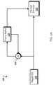
- FIG. 1is a block diagram showing an example of a fault tolerant solid state memory device.
- FIG. 2is a block diagram showing another example of a fault tolerant solid state memory device.
- FIG. 3is a block diagram showing an example of a fault tolerant solid state memory device that includes multiple solid state memory devices.
- FIG. 4shows a conceptual logical grouping of several solid state memory devices.
- FIGS. 5A and 5Bare block diagrams showing examples of parity encoders.
- FIG. 6is a schematic diagram showing an example of a storage controller configured to write data to a physical memory.
- FIG. 7is a block diagram showing an example of a parity data tester.
- FIG. 8is a schematic diagram showing an example of a storage controller configured to read data from a physical memory.
- FIG. 9is a block diagram showing an example of a multiple parity data buffer.
- FIGS. 10A and 10Bshow examples of a look up table for mapping logical indexing to physical indexing.
- FIG. 11is a flow diagram showing an example of a process for storing data and error recovery codes.
- FIG. 12is a flow diagram showing an example of a process for detecting errors in stored data.
- FIG. 13is a flow diagram showing an example of a process for recovering data.
- the systems and techniques described hereincan be implemented as one or more devices, such as one or more integrated circuit (IC) devices in solid state memory devices (e.g., a FLASH drives, a USB storage devices, a solid state drives).
- ICintegrated circuit
- FIG. 1is a block diagram showing an example of a fault tolerant solid state memory device 100 .
- the device 100is a data storage device that uses solid state memory components and related circuitry to provide nonvolatile storage of user and other data.
- solid state memory devicesthat can be embodied by the device 100 include devices commonly referred to as “flash drives”, “USB drives”, “thumb drives”, or solid state disk drives (SSD drives).
- flash drivesUSB drives
- SSD drivessolid state disk drives
- the device 100gains its fault tolerance at least in part by distributing data that is to be stored among multiple memory storage subcomponents, while also calculating and storing error correction (e.g., parity) codes that describe the stored data.
- error correctione.g., parity
- solid state memory devicessuch as the device 100
- a redundant array of independent blockscan be realized within a single SSD, as opposed to a group of solid state drive as is the case with RAID systems.
- the parity informationcan be used as part of a process to recover the data stored in the failed subcomponent.
- the device 100is communicatively connected to a host device 102 (e.g., a computer) by an input port 104 .
- the input port 104can be a universal serial bus (USB), a serial ATA (SATA) bus, a parallel ATA (PATA) bus, FireWire, or any other serial or parallel data bus.
- the device 100includes a storage controller 110 .
- the storage controller 110interfaces the host 102 to a collection of storage devices 120 a - 120 f , such that the host 102 is able to use the storage devices 120 a - 120 f for storage of data.
- Each of the storage devices 120 a - 120 fis a solid state memory device, each of which may include one or more blocks of physical memory.
- the storage devices 120 a - 120 fcan be flash memory devices, NAND devices, or other appropriate types of solid state memory devices. Additional examples of storage devices will be discussed further in the description below in connection with FIGS. 3 and 4 .
- the storage controller 110can organize the storage devices 102 a - 120 f to interface with the host 102 as one or more storage devices.
- Each of the flash devices 120 a - 120 fis subdivided into logical data blocks.
- a logical data blockrepresents the smallest erasable unit of solid state memory within one flash devices 120 a - 120 f .
- Each blockis partitioned into pages.
- a pagemay be the smallest unit of memory that can be read or written to a block.
- a blockmay have 192 4 KB pages. Examples of logical data blocks will be discussed in the description below in connection with FIG. 4 .
- the storage controller 110includes a processor 112 , a dynamic random access memory (DRAM) 114 , a page error-correcting code (ECC) module 116 , and a redundant array of independent blocks (RAIB) encoder 212 .
- the processor 112receives data from the host 102 and buffers the data in the DRAM 114 .
- the DRAM 114may be external to the storage controller 110 .
- the processor 112then processes data received from the host 102 or read from the DRAM 114 by dividing, grouping, or otherwise associating the data into one or more logical data blocks, determining subsets of the flash devices 120 a - 120 f in which to store the logical data blocks as logical block groupings, and storing the data therein. Examples of logical groupings will be discussed further in the description below in connection with of FIG. 4 .
- the datapasses through the page ECC module 116 .
- the page ECC module 116adds error correction code redundancy to each page being sent to the storage devices 120 a - 120 f for storage, and stores the ECC redundancy along with each page.
- the ECC codescan be used to detect and repair errors within the associated page.
- an ECC codecan be used in a process to determine which bits within the page were stored or read erroneously, and recover the originally stored data within the page.
- ECCcan be done on a wordline level.
- single bit celle.g., single level cell, SLC
- flash devicescan be capable of storing two bits (e.g., multi-level cell, MLC), three bits (e.g., three layer cell, TLC), or more bits per cell.
- Such devicescan have wordlines (e.g., rows of cells) that are capable of holding multiple pages.
- one pagecan correspond to the least significant bit (LSB) of each cell, while another page corresponds to a center bit, and yet another page corresponds to most significant bit (MSB) of each cell.
- LSBleast significant bit
- MSBmost significant bit
- page level ECC or word-line level ECCcan be used.
- the RAIB encoder 118process pages to produce RAIB redundancy codes (e.g., error correction code parity data) for logical block groupings.
- the controllermay then store the user data and RAIB redundancy computed by encoder 118 using two or more of the storage devices 120 a - 120 f.
- the datamay then be written page by page while interleaving the pages across the physical memory blocks of a logical block grouping.
- increased throughput and/or reliabilitymay be achieved if blocks within a logical block grouping reside on different storage devices 120 a - 120 f .
- the processor 112may request the RAIB encoder 118 to write parity data to the storage devices 120 a - 120 f before all the user pages have been written to the storage devices 120 a - 120 f .
- the empty user pagesmay be marked as used. For example, writing to used user pages would invalidate the RAIB error correction code structure due to the fact that the RAIB encoder 118 would not be able to update RAIB redundancy since a page can only be written once between two successive block erase operations.
- the processor 112 or the host 102may process the data to determine error correction data and/or control the distribution and storage of the error correction data.
- the processor 112 or the host 102may emulate the functions of the RAIB encoder 118 to group logical data blocks across different devices into logical groupings, and introduce an error correction code for each such logical grouping.
- FIG. 2is a block diagram showing another example of a fault tolerant solid state memory device 200 .
- the device 200interfaces with the host 102 through the data bus 104 to provide solid state memory storage for the host 102 .
- the device 200includes a storage controller 210 .
- the storage controller 210includes the processor 112 , the DRAM 114 , and the page ECC module 116 .
- the storage controller 210also includes a redundant array of independent blocks (RAIB) encoder 212 .
- RAIBredundant array of independent blocks
- the RAIB encoder 212performs substantially the same functions as the RAIB encoder 118 of FIG. 1 , except in this example the controller stores RAIB parity in a dedicated parity device 220 a and 220 b .
- the parity devices 220 a - 220 bare storage devices, similar to the storage devices 120 a - 120 f , that are reserved for the storage of RAIB parity data.
- the RAIB parity data stored on the parity devices 220 a - 220 bcan be used later to recover data stored on the storage devices 120 a - 120 f.
- FIG. 3is a block diagram showing an example of a fault tolerant solid state memory device 300 that includes multiple storage memory devices.
- the concept of fault tolerance in devices such as the device 300is to link the data stored on different storage devices within the device by RAIB parity data.
- fault tolerance techniquese.g., RAID
- RAIDfault tolerance techniques
- a logical way to segregate storage devicescan be done by treating each storage device module, or each die, within the devices 100 , 200 , and 300 as a device that is able to fail independently from other similar devices within the same fault tolerant solid state memory device.
- the device 300includes a storage controller 310 , and a collection of storage devices 320 a - 320 f .
- the storage controller 310includes a processor 312 and a DRAM 314 .
- the processor 312 and the DRAMcan be the processor 112 and the DRAM 114 respectively.
- the storage controller 310also includes a solid state device data path 316 .
- the solid state device data path 316can coordinate the distribution of user data and recovery codes to storage locations among the storage devices 320 a - 320 f.
- Each of the storage devices 320 a - 320 fincludes multiple storage sub-devices, such as the storage sub-devices 322 a - 322 d in 320 a .
- each of the storage sub-devices 322 a - 322 dcan be a single integrated memory circuit, or die.
- Each of the storage sub-devicesis further subdivided into a number of memory blocks, such as memory blocks 324 a - 324 d in the storage sub-device 322 a .
- a physical storage blockcan include the collection of memory blocks 324 a - 324 d , wherein the memory blocks 324 a - 324 d are individually addressable and are all formed on the same integrated circuit die.
- each of the memory blocks 324 a - 324 drepresents a grouping of the smallest erasable unit on the storage sub-device 322 a
- each of the memory blocks 324 a - 324 dincludes a number of pages (not shown) that represent the smallest writeable unit of memory within the memory block.
- the physical structure of the device 300can be taken advantage of for the purposes of creating a fault tolerant storage system. For example, since flash memory generally cannot be overwritten on a page level, once every block has been written the entire block has to be erased before new data can be written onto its pages, therefore there may be no need to consider the use case where some blocks have been modified and the RAIB parity has to be updated accordingly.
- the design of the device 300might not need to accommodate inserting, deleting, or replacing blocks containing user data or RAIB parity data as is generally done in RAID controllers since once the device 300 has been manufactured, it may not be possible to add or remove memory devices.
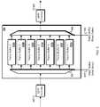
- FIG. 4shows a conceptual logical grouping 400 of several solid state memory devices.
- the groupingrepresents a logical arrangement of the memory devices within a fault tolerant solid state memory device to show an example of logical grouping of memory blocks to provide fault tolerance.
- the grouping 400can be used by the devices 100 , 200 , and/or 300 of FIGS. 1 , 2 , and 3 , respectively.
- the grouping 400includes a storage device 410 a , a storage device 410 b , a storage device 410 c , and a storage device 410 d .
- the storage devices 410 a - 410 dcan be storage devices substantially similar to the storage devices 120 a - 120 f of FIG. 1 .
- one or more of the storage devices 410 a - 410 dcan be the parity devices 220 a - 200 b of FIG. 2 .
- Each of the storage devices 410 a - 410 dincludes a collection of physical memory blocks 420 .
- the physical memory blocks 420are illustrated in a conceptual arrangement of rows and columns, where each storage device (e.g. die) 410 a - 410 d consists of multiple blocks.
- a storage devicecan be used to represent a parallelization structure, for example, the collection of memory units within a single storage memory device that can be written or read at the same time (e.g., multi-plane device).
- a column 430represents the physical memory blocks incorporated into the storage device 410 b.
- the rows of the physical memory blocks 420such as a row 440 represent logical units of memory that include a corresponding block (e.g., the k th block) within each sub-device.
- the row 440represents a logical unit (or a subset thereof as might be the case where there are two planes per device) of memory that can be erased at once.
- the row 440is also used as a logical block grouping of the physical memory blocks 420 for purposes of fault tolerance (e.g., a RAIB stripe, or RAIB ECC code word).
- a storage controllersuch as the storage controller 110 , 210 , or 310 , uses the row 440 to store user data and RAIB redundancy.
- user datacan be divided into blocks that correspond to the size and number of physical memory devices 420 that are designated for storage of user data within the row 440 . More specifically, user data may be written into these blocks one page at a time in the interleaved manner (e.g., first write 0-th page of each block, then write 1-st page of each block, etc.).
- the storage controllermay compute RAIB parity page by performing bitwise XOR operation on the user pages.
- the storage controllercan then store RAIB parity page onto the last free block within row 440 (e.g., not necessarily the right most block as shown on the FIG. 400 ).
- the design of a fault tolerant solid state memory devicemay be partly predicated on the notion that data can be lost due to the failure of a physical device.
- one of the physical memory blocks 420may malfunction, making the data it stores corrupt or inaccessible.
- an entire plane on one devicemay malfunction, thereby causing the physical memory blocks 420 within the plane to be unreadable.
- all the planes within the same deviceare independent (e.g., all the planes within the storage device 410 a may be unreadable if the storage device 410 a were to malfunction).
- several RAIB stripescan be interleaved within a single row in such a way that each RAIB code word does not contain bits from two or more planes on a single storage device module.
- the logical assemblage of the row 440includes one physical memory block 420 from each storage device module.
- the physical memory blocks 420 belonging to a single RAIB stripe within each roware shown with similar fill patterns.
- a collection of physical memory blocks 420 arepresent the physical memory blocks 420 that belong to a stripe that is interleaved into the row 440 such that no more than one physical memory device from any of the storage devices 410 a - 410 d is included in a single RAIB stripe.
- each rowis broken into three RAIB stripes shown with different fill patterns, and each physical unit (e.g., each storage device 410 a - 410 d ) within a RAIB stripe is independent from the other physical units from a failure point of view. More generally, storage devices with N sub-devices can provide N RAIB stripes per row.
- the storage devices 410 a - 410 dare designated for storage of user data and recovery codes.
- the storage controllermay determine which of the physical memory blocks 420 are to be used for the storage of RAIB parity.
- more than one physical memory block 420may be used for storing parity for a single RAIB stripe.
- a RAIB stripe using one block of recovery codemay generally be able to recover the data in a single failed physical memory block within the RAIB stripe.
- this relationshipmay be referred to as a RAIB coderate.
- Single block correcting RAIB coderateis given by (number of devices in a RAIB stripe ⁇ 1)/(number of devices in a RAIB stripe).
- the RAIB coderatewould be (8 ⁇ 1)/8, or 7/8, which means that about 12% of the entire device would be used to store recovery codes.
- the RAIB coderatewould be (8 ⁇ 2)/8, or 3/4, which means that about 25% of the entire device would be used for storage of recovery codes.
- a Reed-Solomon (RS) codemay be used to implement RAIB ECC.
- a RAIB stripecan be chosen to coincide with the row 440 such that the RAIB redundancy occupies a single plane (e.g., sub-device) to yield a higher RAIB coderate (e.g., a smaller fraction of space dedicated to storage of recovery codes) at the expense of reduced data reliability protection due to the possibility of multiple plane failures on the same device. For example, for a fault tolerant solid state memory device with 16 flash devices and two planes per device, this may yield a 31/32 RAIB coderate system.
- the RAIB coderatecan be configurable in response to user selection.
- RAIB stripesmay be desirable to select RAIB stripes to coincide or to be a subset of a logical block grouping used by the controller to carry out memory management (e.g., wear-leveling, garbage collection). Since all the pages within a RAIB stripe may need to be invalidated before any member block can be erased, in some implementations, erasing some of the blocks within the RAIB stripe may result in loss of RAIB recovery code protection. This functionality may be inherent if all the devices within RAIB stripe belong to a single wear leveling unit.
- the storage controllercan group like data within a RAIB stripe (e.g., hot data with hot, cold data with cold), and select like blocks (e.g., blocks with the substantially similar cycle characteristics) to form a stripe.
- a RAIB ECCmay be designed that is capable of recovering more than a single block within RAIB stripe.
- a Reed-Solomon (RS) ECC codemay be used to encode a k-th symbol (e.g. 8 bit symbol) of pages within a RAIB stripe.
- RS ECC codes with generating polynomial of degree Ncan yield a RAIB stripe that is capable of correcting 2N block failures, assuming failed blocks can be identified (e.g., by utilizing page level/wordline level ECC).
- FIG. 5Ais a block diagram showing an example of a parity encoder 500 .
- the parity encoder 500can be included in the storage controllers 110 , 210 , or 310 .
- the parity encoder 500XOR's pages of user data to produce a page of RAIB redundancy code.
- the parity encoder 500is configured to produce a single parity check code for the determination of a single block correcting recovery code.
- the write path 500includes a page ECC encoder 510 .
- the page ECC encoder 510can be the page ECC encoder 116 of FIG. 1 .
- the page ECC encoder 510processes pages of user data to determine error correction code redundancy for a page level ECC.
- the ECC codescan be used to correct errors within individual pages of user data.
- User data and page level ECC redundancy bitsare then stored in a collection of storage devices 520 .
- the write path 500maintains a RAIB parity buffer 530 that stores a partial RAIB parity values. For example, before the first user page of a logical block grouping is written, the parity buffer 530 is reset to zero. As user pages come in, the parity buffer 530 is updated by performing a XOR operation 540 between the content of the parity buffer 530 and the incoming page. Once the last user page of a logical block grouping (e.g. RAIB stripe) has been written, the content of the parity buffer 530 is written to the storage devices 520
- FIG. 5Bis a block diagram showing an example of another parity encoder 501 .
- the parity encoder 501is substantially similar to the parity encoder 500 , except that once the last user page of a logical block grouping has been written, the content of the parity buffer 530 is written to a dedicated parity device 550 .
- additional parity devices 550can be included to guard against multiple device failures.
- An equal or greater number of additional parity buffers 530can also be implemented, wherein each parity buffer 530 can be updated in a similar manner as described previously, with additional control to enable or disable the XOR 540 operation depending on the look up table and the user page index.
- An example of multiple parity bufferswill be discussed further in the description of FIG. 9 .
- An example of a look up table and user page indexeswill be discussed in the description below in connection with FIGS. 10 a and 10 b.
- FIG. 6is a schematic diagram showing an example of a storage controller 600 configured to write data to a physical memory.
- the storage controller 600can be the storage controller 110 of FIG. 1 , the storage controller 210 of FIG. 2 , or the storage controller 310 of FIG. 3 .
- the storage controller 600includes a double data rate (DDR) memory 605 which buffers user data sent from a host device (not shown) for storage in a collection of physical memory devices 610 . Pages of user data buffered in the DDR 605 are processed by a media CRC/LBA 615 .
- the media CRC/LBA 615may perform cyclical redundancy checks, logical block addressing, or both for pages of user data.
- Pages of user dataare received at a switch 620 that is controlled by a signal received from the host through a parity media transfer signal 625 .
- the user pagesare processed by an ECC 630 and stored in a logical block grouping within the physical memory devices 610 .
- Pages of user data emerging from the media CRC/LBA 615are also received at a switch 635 that is controlled by a signal received from the host through a parity buffer reset signal 640 .
- the parity buffer reset signal 640is present, the user page is processed by a memory protection parity (MPP) encoder 645 that determines a CRC value for the data to be stored in the parity buffer 650 .
- MPP encoderreceives XOR of the incoming user page with the content of parity buffer (e.g., representing new running RAIB parity). The user page and CRC is then buffered in a parity buffer 650 .
- a MPP checker module 655uses the CRC value to determine if the data was corrupted while it was stored in parity buffer 650 . If the MPP checker module 655 detects an error in the comparison value, then a parity buffer error signal 660 is set to notify the host of the problem in the comparison value.
- the parity media transfer signal 625also controls a switch 665 .
- the parity media transfer signal 625is set by the memory device controller when RAIB parity data for a logical block grouping is ready to be stored in the collection of physical memory devices 610 .
- the controllersets the parity media transfer signal 625 , thereby causing the switches 665 and 620 to direct the final RAIB parity to be written onto physical memory devices 610 .
- Subsequent user pages assigned to the same logical block groupingare then XORed with previously buffered values.
- the previously buffered valueis XORed with a subsequent user page in an XOR 670 to produce new intermediate RIAB parity values.
- the controllerreleases the parity buffer reset signal 640 , therefore the switch 635 directs the running RAIB parity to be processed by the MPP encoder 645 , buffered as updated running parity values in the parity buffer 650 , and checked by the MPP checker module 655 . This cycle repeats for each subsequent user page assigned to the logical block grouping.
- the RAIB parity datamay describe less than an entire logical block grouping.
- the RAIB encodermay be required to close all opened RAIB stripes by writing corresponding parity buffers to the physical memory devices 610 (e.g., RAIB associations are said to be opened if the content of their parity buffers have not yet been stored). Once the parity buffers are written to the media, all unwritten pages may be marked as invalid. Allowing the host to write data into these pages may necessitate a RAIB parity update operation, which is generally not possible for flash memory devices.
- such a limitationmay be overcome by allowing the use of more than one parity page per RAIB stripe.
- the RAIB encodermay close an open RAIB stripe by storing the current content of the parity buffer to the next available memory block and fill unwritten pages in the RAIB stripe. Once the parity page is written to the media, the XOR of all valid pages within the RAIB stripe is a “0” page. If at a later point the RAIB encoder determines that more pages are to be written into the same RAIB stripe, there is no need to read previously written pages. Each time the RAIB encoder reopens a RAIB parity association, it may write the RAIB parity accumulated during that write session alone.
- a RAIB stripemay include ten pages (0-9).
- the RAIB encodermay receive and process three pages of user data, and those pages can be stored as pages 0, 1, and 2. If at this point, the RAIB encoder is requested to close the RAIB association while the stripe is incomplete (e.g., pages 4-9 have not been written), the RAIB encoder can store the current content of the RAIB buffer (e.g., the XOR of pages 0-2) to the next available page in the stripe (e.g., page 3), and mark the remaining pages 4-9 as invalid.
- the current content of the RAIB buffere.g., the XOR of pages 0-2
- the RAIB encodercan begin encoding new pages once again starting at page 4 and store the corresponding RAIB parity for pages 4-8 in page 9. As such, the recovery code stored in page 9 will be usable for recovering any of the pages 0-8.
- FIG. 7is a block diagram showing an example of a RAIB parity encoder 700 which is capable of performing self-test functions.
- the self-test functionscan be used to automate RAIB feature testing.
- RAIB functionalitymay be employed only in the event of a storage device module failure. Since this is a generally rare event, a way to check RAIB structure integrity is provided.
- the controllerreads all the pages a single RAIB stripe while XOR'ing the contents of the pages as they are read. The normal expectation would be that the parity buffer 650 would be an all “0” page.
- the content of the parity buffer 650is checked by logic 710 , which XOR's all the bits in the page to determine whether the contents of test register 720 ever become non-zero, which may be indicative of errors in the read pages, possibly due to a storage device failure
- the device controllermay attempt to recover the data stored on the failed plane/device. In some implementations, this may be done by reading all the pages in the RAIB stripe, excluding the failed one, and using RAIB ECC to recover the data located on failed devices. More specifically, the failed page can be recovered by XOR'ing remaining pages in the RAIB stripe. In some implementations, if during recovery it is determined that another page in RAIB stripe has failed (e.g. page level ECC failure), then the controller may stop the recovery operation since only one page can be recovered when a single page RAIB recovery code is used. In some implementations, a multi-page recovery RAIB code may be used (e.g., RS ECC) to recover a number of pages equal to or less than the number of pages accommodated by the multi-page recovery code.
- RS ECCmulti-page recovery RAIB code
- FIG. 8is a schematic diagram showing an example of a storage controller 800 configured to read data from a physical memory.
- the storage controller 800may be the storage controller 600 of FIG. 6 in a read configuration.
- the circuitry used to read and write to/from the physical memory devices 610may be separate circuits since they perform different operations (e.g. page level ECC encoder/decoder may operate differently). It may also be preferential to implement separate circuits for the read and write data paths to allow the controller to read and write to/from different ones of the physical memory devices 610 at the same time.
- the RAIB decodermay be activated only in case a memory failure is detected. Since memory failures are generally rare, these are considered as exceptions in the life of the controller. In some implementations where a memory failure is detected, the controller may stop accepting requests from the host to read or write data until the RAIB data recovery is carried out. In some implementations, the RAIB decoder logic may be substantially the same as that of RAIB encoder, and as such the same circuitry used for both RAIB encoding and decoding (e.g., RAIB encoder hardware may be reused to reduce controller size).
- pages of stored data within a logical block groupingare read from the collection of physical memory devices 610 .
- a page level ECC 830checks each page to detect any errors that may be present.
- the hostreleases a parity DDR transfer signal 825 and the pages flow through a switch 805 to a media CRC/LBA 815 and on to the DDR 605 , from which the pages are made available to the host.
- the hostsets the parity DDR transfer signal 825 , such that a switch 810 directs the error-free pages, including the RAIB redundancy, to a switch 835 .
- a parity buffer reset signal 840causes the switch 830 to direct the first good page to an MPP encoder 845 , and the page is buffered in a parity buffer 850 .
- An MPP checker module 855checks the content of the parity buffer before passing them back to a switch 865 and an XOR 870 .
- the hostreleases the parity buffer reset signal, causing incoming error-free pages of the logical block grouping to be XOR'ed with the content of parity buffer 850 .
- This processis repeated for each of the error free pages in the logical block grouping.
- the contents of parity buffer 850represent the page stored on the failed memory block.
- the controllerthen sets the parity DDR transfer signal 825 .
- the signal 825causes the switches 865 and 805 to direct the recovered data to the host.
- FIG. 9is a block diagram showing an example of a multiple parity data buffer 900 .
- the multiple parity data buffer 900can be included in a storage controller, such as the storage controllers 110 , 210 , and 310 .
- the parity data buffercan be the parity buffer 650 of FIG. 6 .
- fault tolerant solid state memory devicescan support multiple logical block groupings to be active (e.g., partly read or written) at the same time. Such implementations can use multiple parity buffers, with one parity buffer being in use for each concurrently active logical block grouping.
- the multiple parity data buffer 900includes a collection of RAIB parity data buffers 910 a - 910 g .
- each of the RAIB parity data buffers 910 a - 910 gcan each save a separate running parity value for a number of active logical block groupings.
- a switch 920is configured to selectably route comparison data, checked by the MPP checker module 645 , to one of the RAIB parity buffers 910 a - 910 g in response to a write parity buffer select signal 930 .
- the signal 930may be sent by the host, or by other components of the storage controller in which the 900 is included.
- the multiple RAIB parity data buffer 900also includes a switch 940 that is configured to selectably route buffered running parity data from a selected one of the buffers 910 a - 910 g to the MPP checker module 655 in response to a read parity data buffer select signal 950 .
- the signal 950may be sent by the storage controller.
- the buffer 900includes a single buffer select input for the switches 920 , 940 ; in which case, the select signals 930 , 950 are combined into a single buffer select signal.
- the single parity data buffers 910 a - 910 gmay be double port memories, wherein N buffers may provide up to N active groupings.
- N buffersmay provide up to N active groupings.
- six double port memoriesmay be implemented to provide up to six active logical block groupings at once.
- the single parity data buffers 910 a - 910 gmay be single port memories, wherein the operations of reading and writing into the memory are interleaved by reading/writing 2N, where N is number of bits that must be processed in a single clock cycle.
- Nnumber of bits that must be processed in a single clock cycle.
- twelve single port memoriesmay be implemented to provide up to twelve active logical block groupings at once.
- Such implementations of single port memory devicesmay enable greater throughput (e.g., one buffer can be written while another buffer can be simultaneously read).
- FIGS. 10A and 10Bshow examples of a look up table 1000 for mapping logical indexing to physical indexing.
- the look up table 1000may be used by a storage controller in conjunction with the multiple parity data buffer 900 .
- the table 1000is represented in a default mapping configuration (e.g., following a reset operation).
- a logical index range 1010 of logical buffer locationsmaps directly to a physical index range 1020 of physical buffer devices in a multiple parity data buffer 900 .
- the storage controlleris able to address “N” logical buffers (e.g., “N” equals six in this example), and the “N+1”th physical buffer is used as a “spare” buffer.
- the storage controllerprovides a parity buffer active signal to select a logical buffer location.
- a range 1030shows the range of logical indexes that can be used by the storage controller.
- the physical buffer corresponding to the active logical bufferis looked up and activated, for example, by setting the parity buffer read select signal 950 .
- the storage controllermay also set the parity buffer write select to the physical buffer corresponding to the spare logical buffer (e.g., physical buffer six in this example).
- the look up table 1000may be modified by updating the buffer corresponding to the selected logical address assigned to the spare buffer, and the buffer corresponding to the logical address “N+1” may be mapped to the physical address given by the parity buffer read select signal. In some implementations, the look up table 1000 may not need to be updated in response to the parity media transfer signal 625 or the parity DDR transfer signal 825 .
- the look up table 1000may be updated by setting the parity buffer read select signal 950 to the physical buffer corresponding to logical buffer N+1, and the parity buffer write select signal 930 may be set to the logical buffer location indicated by the parity buffer active signal. For example, when using the previously described technique the storage controller may set the parity buffer active signal equal to 2, the parity buffer read select signal may be set to 2 and the parity buffer write select signal may be set to 6.
- the look up table 1000updated in such a way, is shown in FIG. 10 b .
- the look up table 1000may be implemented in registers to reduce the need for memory protection of the values stored in the table 1000 .
- FIG. 11is a flow diagram showing an example of a process 1100 for storing data and RIAB parity.
- the process 1100may be used by the storage controllers 110 , 210 , and 310 .
- data to be stored in a solid state memory that includes multiple solid state physical memory devicesis received (e.g., at the storage controller 110 , from the host 102 ).
- the received datais divided into logical data blocks that correspond to the solid state memory.
- the logical data blocksmay be the same as the physical data blocks in which the data is to be stored (e.g., the memory blocks 324 a - 324 d ).
- logical data blocksare assigned to at least one logical block grouping including at least one physical data storage block from each of the multiple solid state physical memory devices (e.g., the row 440 ).
- the data stored in the blocks assigned to the logical block groupingis read.
- the read blockis the first logical data block read from the logical block grouping
- the logical data blockis buffered (e.g., in the parity buffer 650 ) as a buffered value.
- the logical data blockis then stored (e.g., in a physical memory block corresponding to the logical data block of the logical block grouping) at 1114 .
- the read blockis not the first logical data block read from the logical block grouping
- the logical data blockis XORed with the buffered value (e.g., by the XOR 670 ) to produce a running RAIB parity.
- the running RAIB parityis then buffered at 1118 as the buffered value, and the logical data block is stored in physical data storage blocks of the logical block grouping that have been designated for storage of persisted data within the logical block grouping at 1114 .
- multiple bufferse.g., the multiple parity data buffer 900
- the blockis not the last logical data block assigned to the logical block grouping, then another block is selected from the logical block grouping at 1122 and read at 1108 . If, at 1120 , the block is determined to be the last block of the logical block grouping, then a RAIB parity corresponding to the persisted data stored in the logical block grouping is determined at 1124 . In some implementations, the RAIB parity may be the last buffered running RAIB parity.
- the corresponding codeis stored in at least one physical data storage block of the logical block grouping designated for storage of the code that corresponds to the persisted data stored in the logical block grouping. In some implementations, the corresponding code may be a recovery code (e.g., a parity code, RAIB parity data).
- FIG. 12is a flow diagram showing an example of a process 1200 for detecting errors in stored data.
- the process 1200may be used by the storage controllers 110 , 210 , and 310 .
- data stored in the logical data blocks of a logical block grouping within a solid state physical memoryis read (e.g., by the storage controller 110 ).
- the logical data blockis buffered at 1206 (e.g., in the parity data buffer 650 ) as a running RAIB parity. If, however, at 1204 , the block is determined not to be the first block read from the logical block grouping, then the block is XORed (e.g., by the XOR 670 ) to the running RAIB parity at 1208 and buffered at 1210 as the running RAIB parity.
- multiple bufferse.g., the multiple parity data buffer 900
- a predetermined valuee.g., zero
- FIG. 13is a flow diagram showing an example of a process 1300 for recovering data.
- the process 1300may be used by the storage controllers 110 , 210 , and 310 .
- a physical data block that stores inaccessible or erroneous datais selected (e.g., by the storage controller 110 ).
- the logical data block that corresponds to the selected physical data storage blockis identified.
- the logical block grouping to which the logical data block corresponding to the selected physical data storage block is assignedis identified.
- the persisted data stored in the identified logical block grouping, including the corresponding codeis read.
- the logical data blockis buffered at 1312 (e.g., in the buffer 650 ) as a running RAIB parity.
- the logical data blockis XORed (e.g., by the XOR 670 ) to the buffered running RAIB parity.
- the resulting valueis then buffered as the running RAIB parity at 1316 .
- multiple bufferse.g., the multiple parity data buffer 900
- the logical data blockis determined not to be the last block of the logical block grouping, then at 1320 another block of the logical block grouping is selected. If the selected block corresponds to the identified physical block at 1322 (e.g., the block identified at 1302 ), then another block is selected at 1320 . For example, if the newly selected block is the block that has been identified as storing corrupted or inaccessible data, then that block is ignored and another block is selected. Otherwise the selected logical data block is read at 1308 .
- the corresponding codemay be the final buffered running RAIB parity.
- the final parity buffered at 1316can be used as the code that corresponds to the logical block grouping. For instance, if a first page stored the binary value 01101101, and a second page stored the binary value 11010100, then the XOR of the two pages can be 10111001 and stored as the RAIB parity for the two pages. Should the second page become unreadable, then its contents can be recovered by XORing the RAIB parity 10111001 and the first page value 01101101 to give a value of 11010100, which is the value that was originally stored as the second page.
- the corresponding codemay a value that, when combined with the final buffered RIAB parity, will result in a predetermined value (e.g., zero).
- a predetermined valuee.g., zero
- an 8-bit page sizecan buffer values from 0 to 255, and for a final value (e.g., buffered at 1316 ) of 200 and a predetermined value of zero, the corresponding code can be determined to be 56 (e.g., binary 200+binary 56 wraps around to equal a value of zero).
- the corresponding codeis provided (e.g., to the host) as the data stored in the selected physical data storage block.
- the value of 56can be the value originally stored in the damaged block, and can be provided to the host to recover the data lost in the damaged block.
- data processing apparatusencompasses all apparatus, devices, and machines for processing data, including by way of example a programmable processor, a computer, or multiple processors or computers.
- the apparatuscan include, in addition to hardware, code that creates an execution environment for the computer program in question, e.g., code that constitutes processor firmware, a protocol stack, a database management system, an operating system, or a combination of one or more of them.
- a program(also known as a computer program, software, software application, script, or code) can be written in any form of programming language, including compiled or interpreted languages, or declarative or procedural languages, and it can be deployed in any form, including as a stand alone program or as a module, component, subroutine, or other unit suitable for use in a computing environment.
- a programcan be stored in an electronic memory, on magnetic or optical recording media, or on another appropriate tangible, non-transitory computer-readable medium.
- a programdoes not necessarily correspond to a file in a file system.
- a programcan be stored in a portion of a file that holds other programs or data (e.g., one or more scripts stored in a markup language document), in a single file dedicated to the program in question, or in multiple coordinated files (e.g., files that store one or more modules, sub programs, or portions of code).
- a programcan be deployed to be executed on one computer or on multiple computers that are located at one site or distributed across multiple sites and interconnected by a communication network.
Landscapes
- Engineering & Computer Science (AREA)
- Theoretical Computer Science (AREA)
- Physics & Mathematics (AREA)
- General Engineering & Computer Science (AREA)
- General Physics & Mathematics (AREA)
- Quality & Reliability (AREA)
- Techniques For Improving Reliability Of Storages (AREA)
Abstract
Description
Claims (20)
Priority Applications (8)
| Application Number | Priority Date | Filing Date | Title |
|---|---|---|---|
| US12/881,881US8402217B2 (en) | 2009-09-15 | 2010-09-14 | Implementing RAID in solid state memory |
| US13/844,302US8725944B2 (en) | 2009-09-15 | 2013-03-15 | Implementing raid in solid state memory |
| US14/260,237US8977813B2 (en) | 2009-09-15 | 2014-04-23 | Implementing RAID in solid state memory |
| US14/466,881US8988800B1 (en) | 2009-09-15 | 2014-08-22 | Error correction for storage devices |
| US14/642,526US9201731B2 (en) | 2009-09-15 | 2015-03-09 | Error correction for storage devices |
| US14/947,833US9922678B2 (en) | 2009-09-15 | 2015-11-20 | Error correction for storage devices |
| US15/921,610US10186296B2 (en) | 2009-09-15 | 2018-03-14 | Error correction for storage devices |
| US16/253,027US10930315B2 (en) | 2009-09-15 | 2019-01-21 | Error correction for storage devices |
Applications Claiming Priority (3)
| Application Number | Priority Date | Filing Date | Title |
|---|---|---|---|
| US24266209P | 2009-09-15 | 2009-09-15 | |
| US25457709P | 2009-10-23 | 2009-10-23 | |
| US12/881,881US8402217B2 (en) | 2009-09-15 | 2010-09-14 | Implementing RAID in solid state memory |
Related Child Applications (1)
| Application Number | Title | Priority Date | Filing Date |
|---|---|---|---|
| US13/844,302ContinuationUS8725944B2 (en) | 2009-09-15 | 2013-03-15 | Implementing raid in solid state memory |
Publications (2)
| Publication Number | Publication Date |
|---|---|
| US20110066793A1 US20110066793A1 (en) | 2011-03-17 |
| US8402217B2true US8402217B2 (en) | 2013-03-19 |
Family
ID=43731593
Family Applications (3)
| Application Number | Title | Priority Date | Filing Date |
|---|---|---|---|
| US12/881,881Active2031-09-21US8402217B2 (en) | 2009-09-15 | 2010-09-14 | Implementing RAID in solid state memory |
| US13/844,302ActiveUS8725944B2 (en) | 2009-09-15 | 2013-03-15 | Implementing raid in solid state memory |
| US14/260,237ActiveUS8977813B2 (en) | 2009-09-15 | 2014-04-23 | Implementing RAID in solid state memory |
Family Applications After (2)
| Application Number | Title | Priority Date | Filing Date |
|---|---|---|---|
| US13/844,302ActiveUS8725944B2 (en) | 2009-09-15 | 2013-03-15 | Implementing raid in solid state memory |
| US14/260,237ActiveUS8977813B2 (en) | 2009-09-15 | 2014-04-23 | Implementing RAID in solid state memory |
Country Status (2)
| Country | Link |
|---|---|
| US (3) | US8402217B2 (en) |
| CN (1) | CN102023815B (en) |
Cited By (33)
| Publication number | Priority date | Publication date | Assignee | Title |
|---|---|---|---|---|
| US20130033939A1 (en)* | 2011-08-03 | 2013-02-07 | Micron Technology, Inc. | Functional data programming and reading in a memory |
| US20130073895A1 (en)* | 2010-12-01 | 2013-03-21 | Lsi Corporation | Fractional redundant array of silicon independent elements |
| US8601313B1 (en) | 2010-12-13 | 2013-12-03 | Western Digital Technologies, Inc. | System and method for a data reliability scheme in a solid state memory |
| US8601311B2 (en) | 2010-12-14 | 2013-12-03 | Western Digital Technologies, Inc. | System and method for using over-provisioned data capacity to maintain a data redundancy scheme in a solid state memory |
| US8615681B2 (en) | 2010-12-14 | 2013-12-24 | Western Digital Technologies, Inc. | System and method for maintaining a data redundancy scheme in a solid state memory in the event of a power loss |
| US8700951B1 (en) | 2011-03-09 | 2014-04-15 | Western Digital Technologies, Inc. | System and method for improving a data redundancy scheme in a solid state subsystem with additional metadata |
| US8700950B1 (en)* | 2011-02-11 | 2014-04-15 | Western Digital Technologies, Inc. | System and method for data error recovery in a solid state subsystem |
| US8725944B2 (en) | 2009-09-15 | 2014-05-13 | Marvell World Trade Ltd. | Implementing raid in solid state memory |
| US20140223257A1 (en)* | 2013-02-04 | 2014-08-07 | Chi-Sung Oh | Semiconducotr memory device including non-volatile memory cell array |
| US8988800B1 (en) | 2009-09-15 | 2015-03-24 | Marvell International Ltd. | Error correction for storage devices |
| US20150088941A1 (en)* | 2013-09-23 | 2015-03-26 | Google Inc. | Programmatically choosing preferred storage parameters for files in large-scale distributed storage systems based on desired file reliability or availability |
| US9009565B1 (en)* | 2013-03-15 | 2015-04-14 | Pmc-Sierra, Inc. | Systems and methods for mapping for solid-state memory |
| US9021333B1 (en) | 2012-05-22 | 2015-04-28 | Pmc-Sierra, Inc. | Systems and methods for recovering data from failed portions of a flash drive |
| US9021336B1 (en) | 2012-05-22 | 2015-04-28 | Pmc-Sierra, Inc. | Systems and methods for redundantly storing error correction codes in a flash drive with secondary parity information spread out across each page of a group of pages |
| US9021337B1 (en) | 2012-05-22 | 2015-04-28 | Pmc-Sierra, Inc. | Systems and methods for adaptively selecting among different error correction coding schemes in a flash drive |
| US9026867B1 (en)* | 2013-03-15 | 2015-05-05 | Pmc-Sierra, Inc. | Systems and methods for adapting to changing characteristics of multi-level cells in solid-state memory |
| US9047214B1 (en) | 2012-05-22 | 2015-06-02 | Pmc-Sierra, Inc. | System and method for tolerating a failed page in a flash device |
| US9053012B1 (en) | 2013-03-15 | 2015-06-09 | Pmc-Sierra, Inc. | Systems and methods for storing data for solid-state memory |
| US9081701B1 (en) | 2013-03-15 | 2015-07-14 | Pmc-Sierra, Inc. | Systems and methods for decoding data for solid-state memory |
| US9176812B1 (en) | 2012-05-22 | 2015-11-03 | Pmc-Sierra, Inc. | Systems and methods for storing data in page stripes of a flash drive |
| US9183140B2 (en) | 2011-01-18 | 2015-11-10 | Seagate Technology Llc | Higher-level redundancy information computation |
| US9183085B1 (en) | 2012-05-22 | 2015-11-10 | Pmc-Sierra, Inc. | Systems and methods for adaptively selecting from among a plurality of error correction coding schemes in a flash drive for robustness and low latency |
| US9208018B1 (en) | 2013-03-15 | 2015-12-08 | Pmc-Sierra, Inc. | Systems and methods for reclaiming memory for solid-state memory |
| US20160103622A1 (en)* | 2014-10-13 | 2016-04-14 | Silicon Motion, Inc. | Non-volatile memory devices and controllers |
| US9431052B2 (en) | 2014-06-26 | 2016-08-30 | Marvell World Trade Ltd. | Two dimensional magnetic recording systems, devices and methods |
| US20160321184A1 (en)* | 2015-04-30 | 2016-11-03 | Marvell Israel (M.I.S.L) Ltd. | Multiple Read and Write Port Memory |
| US9569306B1 (en)* | 2015-12-18 | 2017-02-14 | International Business Machines Corporation | Recovery of multi-page failures in non-volatile memory system |
| US9858182B2 (en) | 2014-09-11 | 2018-01-02 | Samsung Electronics Co., Ltd. | Storage device and garbage collection method of data storage system having the storage device |
| US10198313B2 (en) | 2016-03-11 | 2019-02-05 | Western Digital Technologies, Inc. | Redundancy of error correction encoded data in a storage system |
| US10198315B2 (en)* | 2016-02-29 | 2019-02-05 | Sandisk Technologies Llc | Non-volatile memory with corruption recovery |
| US10210043B2 (en) | 2014-12-09 | 2019-02-19 | Marvell Israel (M.I.S.L) Ltd. | System and method for performing simultaneous read and write operations in a memory |
| US11403173B2 (en) | 2015-04-30 | 2022-08-02 | Marvell Israel (M.I.S.L) Ltd. | Multiple read and write port memory |
| US11775430B1 (en)* | 2018-03-12 | 2023-10-03 | Amazon Technologies, Inc. | Memory access for multiple circuit components |
Families Citing this family (143)
| Publication number | Priority date | Publication date | Assignee | Title |
|---|---|---|---|---|
| US8719661B1 (en)* | 2010-11-15 | 2014-05-06 | Vmware, Inc. | Transparent and lightweight recovery from hardware memory errors |
| WO2007132453A2 (en) | 2006-05-12 | 2007-11-22 | Anobit Technologies Ltd. | Distortion estimation and cancellation in memory devices |
| WO2007132456A2 (en) | 2006-05-12 | 2007-11-22 | Anobit Technologies Ltd. | Memory device with adaptive capacity |
| KR101202537B1 (en)* | 2006-05-12 | 2012-11-19 | 애플 인크. | Combined distortion estimation and error correction coding for memory devices |
| US7975192B2 (en) | 2006-10-30 | 2011-07-05 | Anobit Technologies Ltd. | Reading memory cells using multiple thresholds |
| WO2008068747A2 (en)* | 2006-12-03 | 2008-06-12 | Anobit Technologies Ltd. | Automatic defect management in memory devices |
| US8151166B2 (en)* | 2007-01-24 | 2012-04-03 | Anobit Technologies Ltd. | Reduction of back pattern dependency effects in memory devices |
| US8369141B2 (en) | 2007-03-12 | 2013-02-05 | Apple Inc. | Adaptive estimation of memory cell read thresholds |
| WO2008139441A2 (en) | 2007-05-12 | 2008-11-20 | Anobit Technologies Ltd. | Memory device with internal signal processing unit |
| US8234545B2 (en) | 2007-05-12 | 2012-07-31 | Apple Inc. | Data storage with incremental redundancy |
| US8259497B2 (en) | 2007-08-06 | 2012-09-04 | Apple Inc. | Programming schemes for multi-level analog memory cells |
| US8174905B2 (en) | 2007-09-19 | 2012-05-08 | Anobit Technologies Ltd. | Programming orders for reducing distortion in arrays of multi-level analog memory cells |
| US8527819B2 (en) | 2007-10-19 | 2013-09-03 | Apple Inc. | Data storage in analog memory cell arrays having erase failures |
| US8270246B2 (en) | 2007-11-13 | 2012-09-18 | Apple Inc. | Optimized selection of memory chips in multi-chips memory devices |
| US8225181B2 (en) | 2007-11-30 | 2012-07-17 | Apple Inc. | Efficient re-read operations from memory devices |
| US8209588B2 (en) | 2007-12-12 | 2012-06-26 | Anobit Technologies Ltd. | Efficient interference cancellation in analog memory cell arrays |
| US8156398B2 (en) | 2008-02-05 | 2012-04-10 | Anobit Technologies Ltd. | Parameter estimation based on error correction code parity check equations |
| US8230300B2 (en) | 2008-03-07 | 2012-07-24 | Apple Inc. | Efficient readout from analog memory cells using data compression |
| US8400858B2 (en) | 2008-03-18 | 2013-03-19 | Apple Inc. | Memory device with reduced sense time readout |
| US8493783B2 (en) | 2008-03-18 | 2013-07-23 | Apple Inc. | Memory device readout using multiple sense times |
| US8498151B1 (en) | 2008-08-05 | 2013-07-30 | Apple Inc. | Data storage in analog memory cells using modified pass voltages |
| US8169825B1 (en) | 2008-09-02 | 2012-05-01 | Anobit Technologies Ltd. | Reliable data storage in analog memory cells subjected to long retention periods |
| US8949684B1 (en) | 2008-09-02 | 2015-02-03 | Apple Inc. | Segmented data storage |
| US8482978B1 (en) | 2008-09-14 | 2013-07-09 | Apple Inc. | Estimation of memory cell read thresholds by sampling inside programming level distribution intervals |
| US8239734B1 (en) | 2008-10-15 | 2012-08-07 | Apple Inc. | Efficient data storage in storage device arrays |
| US8713330B1 (en) | 2008-10-30 | 2014-04-29 | Apple Inc. | Data scrambling in memory devices |
| US8208304B2 (en)* | 2008-11-16 | 2012-06-26 | Anobit Technologies Ltd. | Storage at M bits/cell density in N bits/cell analog memory cell devices, M>N |
| US8174857B1 (en) | 2008-12-31 | 2012-05-08 | Anobit Technologies Ltd. | Efficient readout schemes for analog memory cell devices using multiple read threshold sets |
| US8248831B2 (en) | 2008-12-31 | 2012-08-21 | Apple Inc. | Rejuvenation of analog memory cells |
| US8924661B1 (en) | 2009-01-18 | 2014-12-30 | Apple Inc. | Memory system including a controller and processors associated with memory devices |
| US8228701B2 (en) | 2009-03-01 | 2012-07-24 | Apple Inc. | Selective activation of programming schemes in analog memory cell arrays |
| US8832354B2 (en) | 2009-03-25 | 2014-09-09 | Apple Inc. | Use of host system resources by memory controller |
| US8259506B1 (en) | 2009-03-25 | 2012-09-04 | Apple Inc. | Database of memory read thresholds |
| US8238157B1 (en) | 2009-04-12 | 2012-08-07 | Apple Inc. | Selective re-programming of analog memory cells |
| US8479080B1 (en) | 2009-07-12 | 2013-07-02 | Apple Inc. | Adaptive over-provisioning in memory systems |
| US8495465B1 (en) | 2009-10-15 | 2013-07-23 | Apple Inc. | Error correction coding over multiple memory pages |
| US8677054B1 (en) | 2009-12-16 | 2014-03-18 | Apple Inc. | Memory management schemes for non-volatile memory devices |
| US8694814B1 (en) | 2010-01-10 | 2014-04-08 | Apple Inc. | Reuse of host hibernation storage space by memory controller |
| US8572311B1 (en) | 2010-01-11 | 2013-10-29 | Apple Inc. | Redundant data storage in multi-die memory systems |
| JP2011233186A (en)* | 2010-04-23 | 2011-11-17 | Toshiba Corp | Disk storage unit and data restoration method |
| US8694853B1 (en) | 2010-05-04 | 2014-04-08 | Apple Inc. | Read commands for reading interfering memory cells |
| US8572423B1 (en) | 2010-06-22 | 2013-10-29 | Apple Inc. | Reducing peak current in memory systems |
| US8514630B2 (en) | 2010-07-09 | 2013-08-20 | Sandisk Technologies Inc. | Detection of word-line leakage in memory arrays: current based approach |
| US8432732B2 (en) | 2010-07-09 | 2013-04-30 | Sandisk Technologies Inc. | Detection of word-line leakage in memory arrays |
| US8595591B1 (en) | 2010-07-11 | 2013-11-26 | Apple Inc. | Interference-aware assignment of programming levels in analog memory cells |
| US9104580B1 (en) | 2010-07-27 | 2015-08-11 | Apple Inc. | Cache memory for hybrid disk drives |
| US8645794B1 (en) | 2010-07-31 | 2014-02-04 | Apple Inc. | Data storage in analog memory cells using a non-integer number of bits per cell |
| US8856475B1 (en) | 2010-08-01 | 2014-10-07 | Apple Inc. | Efficient selection of memory blocks for compaction |
| US8493781B1 (en) | 2010-08-12 | 2013-07-23 | Apple Inc. | Interference mitigation using individual word line erasure operations |
| US8694854B1 (en) | 2010-08-17 | 2014-04-08 | Apple Inc. | Read threshold setting based on soft readout statistics |
| US8832507B2 (en)* | 2010-08-23 | 2014-09-09 | Apple Inc. | Systems and methods for generating dynamic super blocks |
| US9021181B1 (en) | 2010-09-27 | 2015-04-28 | Apple Inc. | Memory management for unifying memory cell conditions by using maximum time intervals |
| US8438429B2 (en)* | 2010-12-01 | 2013-05-07 | Hitachi, Ltd. | Storage control apparatus and storage control method |
| US9007836B2 (en)* | 2011-01-13 | 2015-04-14 | Kabushiki Kaisha Toshiba | Non-volatile semiconductor memory device |
| US8578208B2 (en)* | 2011-01-13 | 2013-11-05 | Micron Technology, Inc. | Determining location of error detection data |
| US8379454B2 (en) | 2011-05-05 | 2013-02-19 | Sandisk Technologies Inc. | Detection of broken word-lines in memory arrays |
| KR20120129239A (en)* | 2011-05-19 | 2012-11-28 | 삼성전자주식회사 | Non-volatile memory device, method of operating same, and memory system having same |
| US8726104B2 (en) | 2011-07-28 | 2014-05-13 | Sandisk Technologies Inc. | Non-volatile memory and method with accelerated post-write read using combined verification of multiple pages |
| US8750042B2 (en) | 2011-07-28 | 2014-06-10 | Sandisk Technologies Inc. | Combined simultaneous sensing of multiple wordlines in a post-write read (PWR) and detection of NAND failures |
| US8775901B2 (en) | 2011-07-28 | 2014-07-08 | SanDisk Technologies, Inc. | Data recovery for defective word lines during programming of non-volatile memory arrays |
| KR20130031046A (en)* | 2011-09-20 | 2013-03-28 | 삼성전자주식회사 | Flash memory device and data manage method thererof |
| JP5768654B2 (en)* | 2011-10-25 | 2015-08-26 | ソニー株式会社 | Storage control device, storage device, information processing system, and storage control method |
| US8730722B2 (en) | 2012-03-02 | 2014-05-20 | Sandisk Technologies Inc. | Saving of data in cases of word-line to word-line short in memory arrays |
| US9026887B2 (en) | 2012-03-15 | 2015-05-05 | Micron Technology, Inc. | Physical page, logical page, and codeword correspondence |
| US20130304970A1 (en)* | 2012-04-20 | 2013-11-14 | Stec, Inc. | Systems and methods for providing high performance redundant array of independent disks in a solid-state device |
| KR101925383B1 (en) | 2012-07-23 | 2018-12-05 | 삼성전자주식회사 | Nonvolatile memory device and data managing method thereof |
| US9111648B2 (en)* | 2012-08-28 | 2015-08-18 | Apple Inc. | Redundancy schemes for non-volatile memory based on physical memory layout |
| US8972826B2 (en) | 2012-10-24 | 2015-03-03 | Western Digital Technologies, Inc. | Adaptive error correction codes for data storage systems |
| US9021339B2 (en) | 2012-11-29 | 2015-04-28 | Western Digital Technologies, Inc. | Data reliability schemes for data storage systems |
| US9059736B2 (en) | 2012-12-03 | 2015-06-16 | Western Digital Technologies, Inc. | Methods, solid state drive controllers and data storage devices having a runtime variable raid protection scheme |
| US9026893B1 (en)* | 2012-12-13 | 2015-05-05 | Western Digital Technologies, Inc. | Dynamically assigning inactive pages not used in Reed-Solomon code in non-volatile solid-state storage array |
| US9214963B1 (en) | 2012-12-21 | 2015-12-15 | Western Digital Technologies, Inc. | Method and system for monitoring data channel to enable use of dynamically adjustable LDPC coding parameters in a data storage system |
| CN103092765B (en)* | 2012-12-31 | 2015-08-05 | 记忆科技(深圳)有限公司 | Solid-state memory system, device and method for writing data |
| US9026757B2 (en) | 2013-01-25 | 2015-05-05 | Sandisk Technologies Inc. | Non-volatile memory programming data preservation |
| US8913428B2 (en) | 2013-01-25 | 2014-12-16 | Sandisk Technologies Inc. | Programming non-volatile storage system with multiple memory die |
| US8972776B2 (en)* | 2013-03-06 | 2015-03-03 | Seagate Technology, Llc | Partial R-block recycling |
| US9478271B2 (en)* | 2013-03-14 | 2016-10-25 | Seagate Technology Llc | Nonvolatile memory data recovery after power failure |
| US20140281802A1 (en)* | 2013-03-15 | 2014-09-18 | SEAKR Engineering, Inc. | Multi-dimensional error detection and correction memory and computing architecture |
| CA2812607A1 (en)* | 2013-04-02 | 2014-10-02 | Sunb Ub Moon | A multi-layer usb storage drive with physically separated secure storage layer and non secure storage layer, and with multiple layers |
| JP2015018451A (en)* | 2013-07-11 | 2015-01-29 | 株式会社東芝 | Memory controller, storage device, and memory control method |
| CN105453053B (en) | 2013-08-13 | 2018-10-09 | 英派尔科技开发有限公司 | Storage system |
| US9519577B2 (en)* | 2013-09-03 | 2016-12-13 | Sandisk Technologies Llc | Method and system for migrating data between flash memory devices |
| US9304709B2 (en)* | 2013-09-06 | 2016-04-05 | Western Digital Technologies, Inc. | High performance system providing selective merging of dataframe segments in hardware |
| US9189332B1 (en)* | 2013-09-13 | 2015-11-17 | Seagate Technology Llc | Parity data in solid state memory |
| US9720770B2 (en) | 2013-09-16 | 2017-08-01 | Shannon Systems Ltd. | Method for calculating raids parity code on interleaving and out of order data streams, and a system using the same |
| US9424131B2 (en) | 2013-09-19 | 2016-08-23 | Avago Technologies General Ip (Singapore) Pte. Ltd. | Spatially decoupled redundancy schemes for a solid state drive (SSD) |
| US9165683B2 (en) | 2013-09-23 | 2015-10-20 | Sandisk Technologies Inc. | Multi-word line erratic programming detection |
| WO2015052833A1 (en)* | 2013-10-11 | 2015-04-16 | 株式会社日立製作所 | Storage device, storage system, and storage device control method |
| US9286176B1 (en)* | 2013-11-08 | 2016-03-15 | Western Digital Technologies, Inc. | Selective skipping of blocks in an SSD |
| US9405480B2 (en)* | 2014-01-13 | 2016-08-02 | Seagate Technology Llc | Interleaving codewords over multiple flash planes |
| US20150205667A1 (en)* | 2014-01-23 | 2015-07-23 | DSSD, Inc. | Method and system for service-aware data placement in a storage system |
| US8949692B1 (en) | 2014-01-23 | 2015-02-03 | DSSD, Inc. | Method and system for service-aware parity placement in a storage system |
| US9460809B2 (en) | 2014-07-10 | 2016-10-04 | Sandisk Technologies Llc | AC stress mode to screen out word line to word line shorts |
| US9514835B2 (en) | 2014-07-10 | 2016-12-06 | Sandisk Technologies Llc | Determination of word line to word line shorts between adjacent blocks |
| US9484086B2 (en) | 2014-07-10 | 2016-11-01 | Sandisk Technologies Llc | Determination of word line to local source line shorts |
| US9443612B2 (en) | 2014-07-10 | 2016-09-13 | Sandisk Technologies Llc | Determination of bit line to low voltage signal shorts |
| US9202593B1 (en) | 2014-09-02 | 2015-12-01 | Sandisk Technologies Inc. | Techniques for detecting broken word lines in non-volatile memories |
| US9240249B1 (en) | 2014-09-02 | 2016-01-19 | Sandisk Technologies Inc. | AC stress methods to screen out bit line defects |
| US9449694B2 (en) | 2014-09-04 | 2016-09-20 | Sandisk Technologies Llc | Non-volatile memory with multi-word line select for defect detection operations |
| US9858325B1 (en)* | 2014-09-29 | 2018-01-02 | Amazon Technologies, Inc. | Consolidating data in storage host groupings |
| CN106796544A (en)* | 2014-10-03 | 2017-05-31 | 新加坡科技研究局 | Active Storage Units and Arrays |
| US9619326B2 (en)* | 2014-12-09 | 2017-04-11 | Western Digital Technologies, Inc. | Methods and systems for implementing redundancy in memory controllers |
| WO2016113831A1 (en)* | 2015-01-13 | 2016-07-21 | 株式会社日立製作所 | Storage system and memory control method |
| US9830093B2 (en)* | 2015-03-27 | 2017-11-28 | Intel Corporation | Method and apparatus for improving immunity to defects in a non-volatile memory |
| US9857986B2 (en) | 2015-06-30 | 2018-01-02 | International Business Machines Corporation | Wear leveling of a memory array |
| US9659666B2 (en) | 2015-08-31 | 2017-05-23 | Sandisk Technologies Llc | Dynamic memory recovery at the sub-block level |
| US9946469B2 (en) | 2016-03-21 | 2018-04-17 | Smart Modular Technologies, Inc. | Solid state storage system with latency management mechanism and method of operation thereof |
| US9996417B2 (en) | 2016-04-12 | 2018-06-12 | Apple Inc. | Data recovery in memory having multiple failure modes |
| KR102580123B1 (en)* | 2016-05-03 | 2023-09-20 | 삼성전자주식회사 | Raid storage device and management method thereof |
| KR102573301B1 (en)* | 2016-07-15 | 2023-08-31 | 삼성전자 주식회사 | Memory System performing RAID recovery and Operating Method thereof |
| CN107807788B (en)* | 2016-09-09 | 2021-06-15 | 北京忆恒创源科技有限公司 | Block strip construction method and device and solid-state storage equipment |
| US9996285B2 (en)* | 2016-11-08 | 2018-06-12 | SK Hynix Inc. | Cyclically interleaved XOR array for error recovery |
| US10445199B2 (en)* | 2016-12-22 | 2019-10-15 | Western Digital Technologies, Inc. | Bad page management in storage devices |
| CN106776110A (en)* | 2016-12-29 | 2017-05-31 | 忆正科技(武汉)有限公司 | A kind of control method for reading strategy for solid-state storage |
| CN106873912B (en)* | 2017-02-16 | 2020-02-07 | 苏州浪潮智能科技有限公司 | Dynamic partition storage method, device and system for TLC chip solid state disk |
| US10579471B2 (en)* | 2017-03-02 | 2020-03-03 | Toshiba Memory Corporation | Storage device and error correction method for storage device |
| CN106980594A (en)* | 2017-04-06 | 2017-07-25 | 上海航天测控通信研究所 | A kind of low-cost and high-performance space computer |
| CN108958961B (en)* | 2017-05-22 | 2021-11-30 | 上海宝存信息科技有限公司 | Data storage device and data error management method |
| CN107273304A (en)* | 2017-05-24 | 2017-10-20 | 记忆科技(深圳)有限公司 | A kind of method and solid state hard disc for improving solid state hard disc order reading performance |
| US10453547B2 (en)* | 2017-06-16 | 2019-10-22 | Seagate Technologies Llc | Monitoring a memory for retirement |
| US10474527B1 (en)* | 2017-06-30 | 2019-11-12 | Seagate Technology Llc | Host-assisted error recovery |
| US10585749B2 (en)* | 2017-08-10 | 2020-03-10 | Samsung Electronics Co., Ltd. | System and method for distributed erasure coding |
| US10365967B2 (en) | 2017-08-23 | 2019-07-30 | Toshiba Memory Corporation | On the fly raid parity calculation |
| CN107632947A (en)* | 2017-09-12 | 2018-01-26 | 记忆科技(深圳)有限公司 | A kind of intelligent RAID data protection system |
| CN109600242A (en)* | 2017-09-30 | 2019-04-09 | 美的智慧家居科技有限公司 | For the management method of household electrical appliances distribution, household electrical appliances, client and system |
| US10496472B2 (en)* | 2017-10-18 | 2019-12-03 | Western Digital Technologies, Inc. | Combined XOR buffer memory for multiple open blocks of non-volatile memory |
| US10838805B2 (en)* | 2018-02-23 | 2020-11-17 | Micron Technology, Inc. | Generating parity data based on a characteristic of a stream of data |
| US10762967B2 (en) | 2018-06-28 | 2020-09-01 | Apple Inc. | Recovering from failure in programming a nonvolatile memory |
| US10755787B2 (en) | 2018-06-28 | 2020-08-25 | Apple Inc. | Efficient post programming verification in a nonvolatile memory |
| CN109324756A (en)* | 2018-08-22 | 2019-02-12 | 华中科技大学 | A data security deletion method based on solid state disk array |
| JP2020095548A (en)* | 2018-12-13 | 2020-06-18 | 株式会社日立製作所 | System with non-volatile memory drive |
| US10936455B2 (en) | 2019-02-11 | 2021-03-02 | Apple Inc. | Recovery of data failing due to impairment whose severity depends on bit-significance value |
| US10915394B1 (en) | 2019-09-22 | 2021-02-09 | Apple Inc. | Schemes for protecting data in NVM device using small storage footprint |
| US12321236B2 (en) | 2020-05-11 | 2025-06-03 | Samsung Electronics Co., Ltd. | Systems, methods, and devices for fault resilient storage |
| US12298853B2 (en) | 2020-05-11 | 2025-05-13 | Samsung Electronics Co., Ltd. | Systems, methods, and devices for data recovery with spare storage device and fault resilient storage device |
| US12306717B2 (en) | 2020-05-11 | 2025-05-20 | Samsung Electronics Co., Ltd. | Systems, methods, and devices for data recovery using parity space as recovery space |
| US11138071B1 (en) | 2020-06-22 | 2021-10-05 | Western Digital Technologies, Inc. | On-chip parity buffer management for storage block combining in non-volatile memory |
| CN111897746B (en)* | 2020-07-31 | 2023-06-23 | 广东昆仑信息科技有限公司 | Machine room equipment coding method and system |
| KR20220081610A (en) | 2020-12-09 | 2022-06-16 | 에스케이하이닉스 주식회사 | Controller and memory system including the controller |
| JP7520160B2 (en)* | 2021-03-05 | 2024-07-22 | 長江存儲科技有限責任公司 | Method and apparatus for striping a redundant array of independent disks against programming failures - Patents.com |
| US11556416B2 (en) | 2021-05-05 | 2023-01-17 | Apple Inc. | Controlling memory readout reliability and throughput by adjusting distance between read thresholds |
| US11847342B2 (en) | 2021-07-28 | 2023-12-19 | Apple Inc. | Efficient transfer of hard data and confidence levels in reading a nonvolatile memory |
| US11550657B1 (en) | 2021-09-01 | 2023-01-10 | Apple Inc. | Efficient programming schemes in a nonvolatile memory |
Citations (12)
| Publication number | Priority date | Publication date | Assignee | Title |
|---|---|---|---|---|
| US5737742A (en)* | 1994-06-29 | 1998-04-07 | Hitachi, Ltd. | Memory system using flash memory and method of controlling the memory system |
| US20090228762A1 (en)* | 2008-03-07 | 2009-09-10 | Kabushiki Kaisha Toshiba | Inforamtion Precessing Apparatus and Non-Volatile Semiconductor Memory Drive |
| US7664903B2 (en)* | 2002-02-25 | 2010-02-16 | Solid Access Technologies LLC | Control unit with PCI and SCSI buses and computing system with electronic semiconductor disk |
| US7702880B2 (en)* | 2003-10-01 | 2010-04-20 | Sandisk Corporation | Hybrid mapping implementation within a non-volatile memory system |
| US20100185802A1 (en)* | 2009-01-21 | 2010-07-22 | Micron Technology, Inc. | Solid state memory formatting |
| US20100217919A1 (en)* | 2009-02-24 | 2010-08-26 | Kabushiki Kaisha Toshiba | Memory controller, semiconductor memory device and control method thereof |
| US20100313065A1 (en)* | 2009-06-03 | 2010-12-09 | Micron Technology, Inc. | Object oriented memory in solid state devices |
| US20110010489A1 (en)* | 2009-07-09 | 2011-01-13 | Phison Electronics Corp. | Logical block management method for a flash memory and control circuit storage system using the same |
| US20110191521A1 (en)* | 2009-07-23 | 2011-08-04 | Hitachi, Ltd. | Flash memory device |
| US8041884B2 (en)* | 2005-11-17 | 2011-10-18 | Chee Keng Chang | Controller for non-volatile memories and methods of operating the memory controller |
| US8078794B2 (en)* | 2000-01-06 | 2011-12-13 | Super Talent Electronics, Inc. | Hybrid SSD using a combination of SLC and MLC flash memory arrays |
| US8185713B2 (en)* | 2007-09-19 | 2012-05-22 | Marvell World Travel Ltd. | Flexible sequencer design architecture for solid state memory controller |
Family Cites Families (9)
| Publication number | Priority date | Publication date | Assignee | Title |
|---|---|---|---|---|
| KR100380024B1 (en)* | 2001-01-04 | 2003-04-18 | 삼성전자주식회사 | Semiconductor memory apparatus with redundancy |
| AU2002319569A1 (en)* | 2001-07-26 | 2003-02-17 | Kyocera Wireless Corporation | System and method for organizing field upgradable wireless communication device software |
| US8140795B2 (en)* | 2005-02-28 | 2012-03-20 | Lenovo (Singapore) Pte. Ltd. | Hard disk drive with write-only region |
| CN1321377C (en)* | 2005-06-16 | 2007-06-13 | 北京航空航天大学 | Control method of smart card storage environment |
| US8935302B2 (en)* | 2006-12-06 | 2015-01-13 | Intelligent Intellectual Property Holdings 2 Llc | Apparatus, system, and method for data block usage information synchronization for a non-volatile storage volume |
| US8001444B2 (en)* | 2007-08-08 | 2011-08-16 | Intel Corporation | ECC functional block placement in a multi-channel mass storage device |
| US8806300B2 (en)* | 2009-05-25 | 2014-08-12 | Hitachi, Ltd. | Storage subsystem |
| WO2011024239A1 (en)* | 2009-08-31 | 2011-03-03 | Hitachi, Ltd. | Storage system having plurality of flash packages |
| US8402217B2 (en) | 2009-09-15 | 2013-03-19 | Marvell International Ltd. | Implementing RAID in solid state memory |
- 2010
- 2010-09-14USUS12/881,881patent/US8402217B2/enactiveActive
- 2010-09-15CNCN201010285233.2Apatent/CN102023815B/enactiveActive
- 2013
- 2013-03-15USUS13/844,302patent/US8725944B2/enactiveActive
- 2014
- 2014-04-23USUS14/260,237patent/US8977813B2/enactiveActive
Patent Citations (12)
| Publication number | Priority date | Publication date | Assignee | Title |
|---|---|---|---|---|
| US5737742A (en)* | 1994-06-29 | 1998-04-07 | Hitachi, Ltd. | Memory system using flash memory and method of controlling the memory system |
| US8078794B2 (en)* | 2000-01-06 | 2011-12-13 | Super Talent Electronics, Inc. | Hybrid SSD using a combination of SLC and MLC flash memory arrays |
| US7664903B2 (en)* | 2002-02-25 | 2010-02-16 | Solid Access Technologies LLC | Control unit with PCI and SCSI buses and computing system with electronic semiconductor disk |
| US7702880B2 (en)* | 2003-10-01 | 2010-04-20 | Sandisk Corporation | Hybrid mapping implementation within a non-volatile memory system |
| US8041884B2 (en)* | 2005-11-17 | 2011-10-18 | Chee Keng Chang | Controller for non-volatile memories and methods of operating the memory controller |
| US8185713B2 (en)* | 2007-09-19 | 2012-05-22 | Marvell World Travel Ltd. | Flexible sequencer design architecture for solid state memory controller |
| US20090228762A1 (en)* | 2008-03-07 | 2009-09-10 | Kabushiki Kaisha Toshiba | Inforamtion Precessing Apparatus and Non-Volatile Semiconductor Memory Drive |
| US20100185802A1 (en)* | 2009-01-21 | 2010-07-22 | Micron Technology, Inc. | Solid state memory formatting |
| US20100217919A1 (en)* | 2009-02-24 | 2010-08-26 | Kabushiki Kaisha Toshiba | Memory controller, semiconductor memory device and control method thereof |
| US20100313065A1 (en)* | 2009-06-03 | 2010-12-09 | Micron Technology, Inc. | Object oriented memory in solid state devices |
| US20110010489A1 (en)* | 2009-07-09 | 2011-01-13 | Phison Electronics Corp. | Logical block management method for a flash memory and control circuit storage system using the same |
| US20110191521A1 (en)* | 2009-07-23 | 2011-08-04 | Hitachi, Ltd. | Flash memory device |
Non-Patent Citations (1)
| Title |
|---|
| Schwarz et al., "RAID Organization and Performance," Jun. 1992, Distributed Computing Systems, Proceedings of the 12th International Conference on Parallel and Distributed Systems, 9 pages. |
Cited By (49)
| Publication number | Priority date | Publication date | Assignee | Title |
|---|---|---|---|---|
| US8725944B2 (en) | 2009-09-15 | 2014-05-13 | Marvell World Trade Ltd. | Implementing raid in solid state memory |
| US10930315B2 (en) | 2009-09-15 | 2021-02-23 | Marvell Asia Pte., Ltd. | Error correction for storage devices |
| US10186296B2 (en) | 2009-09-15 | 2019-01-22 | Marvell World Trade Ltd. | Error correction for storage devices |
| US9922678B2 (en) | 2009-09-15 | 2018-03-20 | Marvell World Trade Ltd. | Error correction for storage devices |
| US9201731B2 (en) | 2009-09-15 | 2015-12-01 | Marvell World Trade Ltd. | Error correction for storage devices |
| US8988800B1 (en) | 2009-09-15 | 2015-03-24 | Marvell International Ltd. | Error correction for storage devices |
| US8977813B2 (en) | 2009-09-15 | 2015-03-10 | Marvell World Trade Ltd. | Implementing RAID in solid state memory |
| US9727414B2 (en)* | 2010-12-01 | 2017-08-08 | Seagate Technology Llc | Fractional redundant array of silicon independent elements |
| US20130073895A1 (en)* | 2010-12-01 | 2013-03-21 | Lsi Corporation | Fractional redundant array of silicon independent elements |
| US8601313B1 (en) | 2010-12-13 | 2013-12-03 | Western Digital Technologies, Inc. | System and method for a data reliability scheme in a solid state memory |
| US8601311B2 (en) | 2010-12-14 | 2013-12-03 | Western Digital Technologies, Inc. | System and method for using over-provisioned data capacity to maintain a data redundancy scheme in a solid state memory |
| US8615681B2 (en) | 2010-12-14 | 2013-12-24 | Western Digital Technologies, Inc. | System and method for maintaining a data redundancy scheme in a solid state memory in the event of a power loss |
| US9183140B2 (en) | 2011-01-18 | 2015-11-10 | Seagate Technology Llc | Higher-level redundancy information computation |
| US8700950B1 (en)* | 2011-02-11 | 2014-04-15 | Western Digital Technologies, Inc. | System and method for data error recovery in a solid state subsystem |
| US9405617B1 (en) | 2011-02-11 | 2016-08-02 | Western Digital Technologies, Inc. | System and method for data error recovery in a solid state subsystem |
| US9110835B1 (en) | 2011-03-09 | 2015-08-18 | Western Digital Technologies, Inc. | System and method for improving a data redundancy scheme in a solid state subsystem with additional metadata |
| US8700951B1 (en) | 2011-03-09 | 2014-04-15 | Western Digital Technologies, Inc. | System and method for improving a data redundancy scheme in a solid state subsystem with additional metadata |
| US10115465B2 (en) | 2011-08-03 | 2018-10-30 | Micron Technology, Inc. | Functional data programming in a non-volatile memory |
| US20130033939A1 (en)* | 2011-08-03 | 2013-02-07 | Micron Technology, Inc. | Functional data programming and reading in a memory |
| US9449692B2 (en)* | 2011-08-03 | 2016-09-20 | Micron Technology, Inc. | Functional data programming and reading in a memory |
| US9620234B2 (en) | 2011-08-03 | 2017-04-11 | Micron Technology, Inc. | Functional data reading in a non-volatile memory |
| US9021336B1 (en) | 2012-05-22 | 2015-04-28 | Pmc-Sierra, Inc. | Systems and methods for redundantly storing error correction codes in a flash drive with secondary parity information spread out across each page of a group of pages |
| US9021337B1 (en) | 2012-05-22 | 2015-04-28 | Pmc-Sierra, Inc. | Systems and methods for adaptively selecting among different error correction coding schemes in a flash drive |
| US9183085B1 (en) | 2012-05-22 | 2015-11-10 | Pmc-Sierra, Inc. | Systems and methods for adaptively selecting from among a plurality of error correction coding schemes in a flash drive for robustness and low latency |
| US9021333B1 (en) | 2012-05-22 | 2015-04-28 | Pmc-Sierra, Inc. | Systems and methods for recovering data from failed portions of a flash drive |
| US9176812B1 (en) | 2012-05-22 | 2015-11-03 | Pmc-Sierra, Inc. | Systems and methods for storing data in page stripes of a flash drive |
| US9047214B1 (en) | 2012-05-22 | 2015-06-02 | Pmc-Sierra, Inc. | System and method for tolerating a failed page in a flash device |
| US20140223257A1 (en)* | 2013-02-04 | 2014-08-07 | Chi-Sung Oh | Semiconducotr memory device including non-volatile memory cell array |
| US9436545B2 (en)* | 2013-02-04 | 2016-09-06 | Samsung Electronics Co., Ltd. | Semiconducotr memory device including non-volatile memory cell array |
| US9026867B1 (en)* | 2013-03-15 | 2015-05-05 | Pmc-Sierra, Inc. | Systems and methods for adapting to changing characteristics of multi-level cells in solid-state memory |
| US9208018B1 (en) | 2013-03-15 | 2015-12-08 | Pmc-Sierra, Inc. | Systems and methods for reclaiming memory for solid-state memory |
| US9009565B1 (en)* | 2013-03-15 | 2015-04-14 | Pmc-Sierra, Inc. | Systems and methods for mapping for solid-state memory |
| US9081701B1 (en) | 2013-03-15 | 2015-07-14 | Pmc-Sierra, Inc. | Systems and methods for decoding data for solid-state memory |
| US9053012B1 (en) | 2013-03-15 | 2015-06-09 | Pmc-Sierra, Inc. | Systems and methods for storing data for solid-state memory |
| US9411817B2 (en)* | 2013-09-23 | 2016-08-09 | Google Inc. | Programmatically choosing preferred storage parameters for files in large-scale distributed storage systems based on desired file reliability or availability |
| US20150088941A1 (en)* | 2013-09-23 | 2015-03-26 | Google Inc. | Programmatically choosing preferred storage parameters for files in large-scale distributed storage systems based on desired file reliability or availability |
| US9431052B2 (en) | 2014-06-26 | 2016-08-30 | Marvell World Trade Ltd. | Two dimensional magnetic recording systems, devices and methods |
| US9728221B2 (en) | 2014-06-26 | 2017-08-08 | Marvell World Trade Ltd. | Two dimensional magnetic recording system, devices and methods |
| US9858182B2 (en) | 2014-09-11 | 2018-01-02 | Samsung Electronics Co., Ltd. | Storage device and garbage collection method of data storage system having the storage device |
| US20160103622A1 (en)* | 2014-10-13 | 2016-04-14 | Silicon Motion, Inc. | Non-volatile memory devices and controllers |
| US9430159B2 (en)* | 2014-10-13 | 2016-08-30 | Silicon Motion, Inc. | Non-volatile memory devices and controllers |
| US10210043B2 (en) | 2014-12-09 | 2019-02-19 | Marvell Israel (M.I.S.L) Ltd. | System and method for performing simultaneous read and write operations in a memory |
| US10387322B2 (en)* | 2015-04-30 | 2019-08-20 | Marvell Israel (M.I.S.L.) Ltd. | Multiple read and write port memory |
| US20160321184A1 (en)* | 2015-04-30 | 2016-11-03 | Marvell Israel (M.I.S.L) Ltd. | Multiple Read and Write Port Memory |
| US11403173B2 (en) | 2015-04-30 | 2022-08-02 | Marvell Israel (M.I.S.L) Ltd. | Multiple read and write port memory |
| US9569306B1 (en)* | 2015-12-18 | 2017-02-14 | International Business Machines Corporation | Recovery of multi-page failures in non-volatile memory system |
| US10198315B2 (en)* | 2016-02-29 | 2019-02-05 | Sandisk Technologies Llc | Non-volatile memory with corruption recovery |
| US10198313B2 (en) | 2016-03-11 | 2019-02-05 | Western Digital Technologies, Inc. | Redundancy of error correction encoded data in a storage system |
| US11775430B1 (en)* | 2018-03-12 | 2023-10-03 | Amazon Technologies, Inc. | Memory access for multiple circuit components |
Also Published As
| Publication number | Publication date |
|---|---|
| US8977813B2 (en) | 2015-03-10 |
| CN102023815B (en) | 2016-01-20 |
| US20140237287A1 (en) | 2014-08-21 |
| US8725944B2 (en) | 2014-05-13 |
| US20130227202A1 (en) | 2013-08-29 |
| US20110066793A1 (en) | 2011-03-17 |
| CN102023815A (en) | 2011-04-20 |
Similar Documents
| Publication | Publication Date | Title |
|---|---|---|
| US8977813B2 (en) | Implementing RAID in solid state memory | |
| JP5853040B2 (en) | Non-volatile multilevel memory operation based on stripes | |
| US8327224B2 (en) | Data recovery in a solid state storage system | |
| US9262261B2 (en) | Memory devices facilitating differing depths of error detection and/or error correction coverage | |
| US8631294B2 (en) | Methods and devices to increase memory device data reliability | |
| US10339343B2 (en) | Storage system and method for improved generation and storage of data protection information | |
| US11704196B2 (en) | Reduced parity data management | |
| US11789813B2 (en) | Memory device crossed matrix parity | |
| CN116266473B (en) | Memory device crossbar matrix parity check | |
| US12197743B2 (en) | Parity protection in non-volatile memory | |
| US20210019082A1 (en) | Nonvolatile memory bad row management |
Legal Events
| Date | Code | Title | Description |
|---|---|---|---|
| AS | Assignment | Owner name:MARVELL SEMICONDUCTOR, INC., CALIFORNIA Free format text:ASSIGNMENT OF ASSIGNORS INTEREST;ASSIGNOR:BURD, GREGORY;REEL/FRAME:025009/0478 Effective date:20100913 Owner name:MARVELL INTERNATIONAL LTD., BERMUDA Free format text:LICENSE;ASSIGNOR:MARVELL WORLD TRADE LTD.;REEL/FRAME:025009/0534 Effective date:20100916 Owner name:MARVELL WORLD TRADE LTD., BARBADOS Free format text:ASSIGNMENT OF ASSIGNORS INTEREST;ASSIGNOR:MARVELL INTERNATIONAL, LTD.;REEL/FRAME:025009/0492 Effective date:20100916 Owner name:MARVELL INTERNATIONAL LTD., BERMUDA Free format text:ASSIGNMENT OF ASSIGNORS INTEREST;ASSIGNOR:MARVELL SEMICONDUCTOR, INC.;REEL/FRAME:025009/0485 Effective date:20100916 | |
| STCF | Information on status: patent grant | Free format text:PATENTED CASE | |
| FPAY | Fee payment | Year of fee payment:4 | |
| AS | Assignment | Owner name:MARVELL INTERNATIONAL LTD., BERMUDA Free format text:ASSIGNMENT OF ASSIGNORS INTEREST;ASSIGNOR:MARVELL WORLD TRADE LTD.;REEL/FRAME:051778/0537 Effective date:20191231 | |
| AS | Assignment | Owner name:CAVIUM INTERNATIONAL, CAYMAN ISLANDS Free format text:ASSIGNMENT OF ASSIGNORS INTEREST;ASSIGNOR:MARVELL INTERNATIONAL LTD.;REEL/FRAME:052918/0001 Effective date:20191231 | |
| AS | Assignment | Owner name:MARVELL ASIA PTE, LTD., SINGAPORE Free format text:ASSIGNMENT OF ASSIGNORS INTEREST;ASSIGNOR:CAVIUM INTERNATIONAL;REEL/FRAME:053475/0001 Effective date:20191231 | |
| MAFP | Maintenance fee payment | Free format text:PAYMENT OF MAINTENANCE FEE, 8TH YEAR, LARGE ENTITY (ORIGINAL EVENT CODE: M1552); ENTITY STATUS OF PATENT OWNER: LARGE ENTITY Year of fee payment:8 | |
| MAFP | Maintenance fee payment | Free format text:PAYMENT OF MAINTENANCE FEE, 12TH YEAR, LARGE ENTITY (ORIGINAL EVENT CODE: M1553); ENTITY STATUS OF PATENT OWNER: LARGE ENTITY Year of fee payment:12 |