US8399273B2 - Light-emitting diode with current-spreading region - Google Patents
Light-emitting diode with current-spreading regionDownload PDFInfo
- Publication number
- US8399273B2 US8399273B2US12/539,757US53975709AUS8399273B2US 8399273 B2US8399273 B2US 8399273B2US 53975709 AUS53975709 AUS 53975709AUS 8399273 B2US8399273 B2US 8399273B2
- Authority
- US
- United States
- Prior art keywords
- layer
- forming
- electrode
- group iii
- over
- Prior art date
- Legal status (The legal status is an assumption and is not a legal conclusion. Google has not performed a legal analysis and makes no representation as to the accuracy of the status listed.)
- Expired - Fee Related, expires
Links
Images


Classifications
- H—ELECTRICITY
- H10—SEMICONDUCTOR DEVICES; ELECTRIC SOLID-STATE DEVICES NOT OTHERWISE PROVIDED FOR
- H10H—INORGANIC LIGHT-EMITTING SEMICONDUCTOR DEVICES HAVING POTENTIAL BARRIERS
- H10H20/00—Individual inorganic light-emitting semiconductor devices having potential barriers, e.g. light-emitting diodes [LED]
- H10H20/80—Constructional details
- H10H20/81—Bodies
- H10H20/816—Bodies having carrier transport control structures, e.g. highly-doped semiconductor layers or current-blocking structures
- H10H20/8162—Current-blocking structures
- H—ELECTRICITY
- H10—SEMICONDUCTOR DEVICES; ELECTRIC SOLID-STATE DEVICES NOT OTHERWISE PROVIDED FOR
- H10H—INORGANIC LIGHT-EMITTING SEMICONDUCTOR DEVICES HAVING POTENTIAL BARRIERS
- H10H20/00—Individual inorganic light-emitting semiconductor devices having potential barriers, e.g. light-emitting diodes [LED]
- H10H20/01—Manufacture or treatment
- H10H20/011—Manufacture or treatment of bodies, e.g. forming semiconductor layers
- H10H20/013—Manufacture or treatment of bodies, e.g. forming semiconductor layers having light-emitting regions comprising only Group III-V materials
- H10H20/0133—Manufacture or treatment of bodies, e.g. forming semiconductor layers having light-emitting regions comprising only Group III-V materials with a substrate not being Group III-V materials
- H—ELECTRICITY
- H10—SEMICONDUCTOR DEVICES; ELECTRIC SOLID-STATE DEVICES NOT OTHERWISE PROVIDED FOR
- H10H—INORGANIC LIGHT-EMITTING SEMICONDUCTOR DEVICES HAVING POTENTIAL BARRIERS
- H10H20/00—Individual inorganic light-emitting semiconductor devices having potential barriers, e.g. light-emitting diodes [LED]
- H10H20/80—Constructional details
- H10H20/81—Bodies
- H10H20/811—Bodies having quantum effect structures or superlattices, e.g. tunnel junctions
- H10H20/812—Bodies having quantum effect structures or superlattices, e.g. tunnel junctions within the light-emitting regions, e.g. having quantum confinement structures
- H—ELECTRICITY
- H10—SEMICONDUCTOR DEVICES; ELECTRIC SOLID-STATE DEVICES NOT OTHERWISE PROVIDED FOR
- H10H—INORGANIC LIGHT-EMITTING SEMICONDUCTOR DEVICES HAVING POTENTIAL BARRIERS
- H10H20/00—Individual inorganic light-emitting semiconductor devices having potential barriers, e.g. light-emitting diodes [LED]
- H10H20/80—Constructional details
- H10H20/81—Bodies
- H10H20/822—Materials of the light-emitting regions
- H10H20/824—Materials of the light-emitting regions comprising only Group III-V materials, e.g. GaP
- H—ELECTRICITY
- H10—SEMICONDUCTOR DEVICES; ELECTRIC SOLID-STATE DEVICES NOT OTHERWISE PROVIDED FOR
- H10H—INORGANIC LIGHT-EMITTING SEMICONDUCTOR DEVICES HAVING POTENTIAL BARRIERS
- H10H20/00—Individual inorganic light-emitting semiconductor devices having potential barriers, e.g. light-emitting diodes [LED]
- H10H20/80—Constructional details
- H10H20/83—Electrodes
- H—ELECTRICITY
- H10—SEMICONDUCTOR DEVICES; ELECTRIC SOLID-STATE DEVICES NOT OTHERWISE PROVIDED FOR
- H10H—INORGANIC LIGHT-EMITTING SEMICONDUCTOR DEVICES HAVING POTENTIAL BARRIERS
- H10H20/00—Individual inorganic light-emitting semiconductor devices having potential barriers, e.g. light-emitting diodes [LED]
- H10H20/80—Constructional details
- H10H20/85—Packages
- H10H20/857—Interconnections, e.g. lead-frames, bond wires or solder balls
- H—ELECTRICITY
- H10—SEMICONDUCTOR DEVICES; ELECTRIC SOLID-STATE DEVICES NOT OTHERWISE PROVIDED FOR
- H10H—INORGANIC LIGHT-EMITTING SEMICONDUCTOR DEVICES HAVING POTENTIAL BARRIERS
- H10H20/00—Individual inorganic light-emitting semiconductor devices having potential barriers, e.g. light-emitting diodes [LED]
- H10H20/01—Manufacture or treatment
- H10H20/036—Manufacture or treatment of packages
- H10H20/0364—Manufacture or treatment of packages of interconnections
Definitions
- This inventionrelates generally to semiconductor devices and, more particularly, to crystalline group III-V light-emitting diodes.
- LEDsLight-emitting diodes
- the radiative recombination of electron-hole pairscan be used for the generation of electromagnetic radiation (e.g., light) by the electric current in a p-n junction.
- electromagnetic radiatione.g., light
- the recombination of the electron-hole pairs injected into the depletion regioncauses the emission of electromagnetic radiation.
- the electromagnetic radiationmay be in the visible range or may be in a non-visible range. Different color LEDs may be created by using materials with different band gaps.
- an LED emitting electromagnetic radiation at a particular wavelength rangemay direct the radiation towards a phosphor that absorbs the radiation and emits radiation of one or more different wavelengths. So, for example, an LED emitting non-visible light may direct that light toward a phosphor that transforms the non-visible light into visible light.
- LED structureshave a light-emitting layer interposed between a lower layer and an upper layer, wherein the upper layer and the lower layer have opposite types of conductivity. Electrodes are formed to contact the lower and the upper layers. Current flowing from between the electrodes and the light-emitting layer takes the least electrically resistive path. In many configurations in which the upper electrode is positioned directly above the light-emitting layer, much of the light emitted by the light-emitting layer is blocked by the upper electrode, thereby significantly decreasing the light efficiency of the LED structure.
- One attempt to limit the light-blocking effect of the upper electrode to increase the light efficiency of the LED structureinvolves forming a dielectric layer on a portion of the light-emitting layer prior to the forming of the upper layer.
- the upper electrodeis positioned over the dielectric layer such that current flowing between the upper electrode and the lower layer of the LED structure are forced around the dielectric layer.
- the currentflows between the upper layer and the lower layer at locations not directly under the upper electrode, thereby limiting the amount of light blocked by the upper electrode and increasing the light efficiency of the LED structure.
- the dielectric layeris typically formed by depositing and patterning a layer of silicon dioxide on the light-emitting layer.
- the deposition and patterning stepsadd additional cost and complexity to the standard LED fabrication process.
- the patterning stepstypically comprise an etch process that may damage the surface of the light-emitting layer and reduce its crystal quality. This damage may adversely affect the quality of the LED devices and reduce the yield.
- LEDslight-emitting diodes
- an LED devicein accordance with one aspect of the present invention, includes a substrate having an LED structure formed thereon.
- the LED structureincludes a lower layer, a light-emitting layer, and an upper layer.
- a current blocking layeris formed in the upper layer such that the upper layer maintains a planar surface.
- the current blocking layermay be formed by, for example, implanting ions, such as magnesium, carbon, silicon, or other ions, into the upper layer to create a resistive region.
- Another upper layermay be formed over the upper layer after the ion implant.
- a method of forming an LED deviceincludes providing a substrate and forming an LED structure on the substrate, wherein the LED structure includes a first layer, an active layer, and a second layer. Thereafter, a current blocking layer is formed in the second layer by, for example, forming a resistive region.
- the resistive regionmay be formed by, for example, implantation. After implanting, another layer may be formed over the second layer.
- another method of forming an LED deviceincludes providing a substrate and forming an LED structure on the substrate.
- the LED structuremay include one or more lower layers, one or more light-emitting layers, and one or more first upper layers. Ions are implanted into at least one of the one or more first upper layers to form a resistive layer.
- One or more second upper layersmay be formed over the one or more first upper layers.
- FIGS. 1-3illustrate various process steps of manufacturing a light-emitting diode device in accordance with an embodiment of the present invention.
- FIGS. 4 and 5illustrate various process steps of manufacturing a light-emitting diode device in accordance with another embodiment of the present invention.
- FIGS. 1-3illustrate various intermediate process steps of forming a light-emitting diode (LED) device 100 with a current-blocking layer in accordance with an embodiment of the present invention.
- the LED device 100is shown as including a substrate 102 with an LED structure 104 formed thereon.
- the substrate 102is preferably a bulk sapphire or silicon substrate, doped or undoped. It should be noted that while embodiments of the present invention are described in the context of using a sapphire substrate, other substrates may be used. For example, other substrates commonly employed in the fabrication of LEDs, such as SiC substrates, may also be used in certain embodiments. Furthermore, substrates with various surface orientations, such as (111), (100), or (110) may be used.
- the LED structure 104may comprise any LED structure suitable for a particular application.
- the LED structure 104includes a lower LED layer 110 formed over the surface of the substrate 102 .
- the lower LED layer 110is formed of a group III-V compound doped with a dopant of a first conductivity type.
- a group III-N compoundsuch as n-GaN having an n-type conductivity may be used.
- the lower LED layer 110 of n-GaNmay be formed by, for example, a selective epitaxial growth process such as a molecular-beam epitaxy (MBE), metal organic chemical vapor deposition (MOCVD), hydride vapor phase epitaxy (HVPE), liquid phase epitaxy (LPE), or the like.
- MBEmolecular-beam epitaxy
- MOCVDmetal organic chemical vapor deposition
- HVPEhydride vapor phase epitaxy
- LPEliquid phase epitaxy
- group III-N materialsthat may be used include, for example, GaN, InN, AlN, In x Ga (1-x) N, Al x Ga (1-x) N, Al x In y Ga (1-x-y) N, or the like.
- Other group III-V materialsmay also be used.
- a light-emitting layer 112(also sometimes referred to as an active layer) is formed on the lower LED layer 110 .
- the light-emitting layer 112may include a homojunction, heterojunction, single-quantum well (SQW), multiple-quantum well (MQW), or the like, structure.
- light-emitting layer 112comprises undoped n-type gallium indium nitride (Ga x In y N (1-x-y) ).
- light-emitting layer 112includes other commonly used materials such as Al x In y Ga (1-x-y) N.
- light-emitting layer 112may be a multiple quantum well including multiple well layers (such as InGaN) and barrier layers (such as GaN) allocated in an alternating pattern.
- the formation methodsinclude MOCVD, MBE, HVPE, LPE, or other applicable CVD methods.
- the upper LED layer 114is disposed on the light-emitting layer 112 .
- the upper LED layer 114is preferably formed of a group III-N compound doped with a dopant of a second conductivity type, opposite of the first conductivity type, such as p-GaN, and may be formed by a process similar to the lower LED layer 110 .
- LED structurefor illustrative purposes.
- Other layerssuch as a distributed Bragg reflector, omni-directional reflectors, buffer/nucleation layers, cladding/contact layers, or the like, may also be present as required and/or desired for a particular application.
- a layerwas described as a single layer, a plurality of layers may be used comprising of the same or different materials.
- the lower and upper LED layersmay each comprise one or more contact layers and one or more cladding layers, which may both be formed of the same or different materials.
- the structure of the LED structuremay also vary depending on the type of materials used and the intended application. It is expected that many types of LED structures may be used with embodiments of the present invention.
- FIG. 2illustrates the formation of a current-blocking layer (CBL) 202 in the upper LED layer 114 in accordance with an embodiment of the present invention.
- the CBL 202comprises a region formed in the upper LED layer 114 , or other conductive layer/substrate formed over the LED structure 104 , of a resistive material. It should be noted that the CBL 202 is positioned along the bottom of the upper LED layer 114 for illustrative purposes only. The CBL 202 may be positioned at any vertical position within the upper LED layer 114 . For example, the CBL 202 may be positioned along the top surface or in the middle of the upper LED layer 114 .
- the region of resistive material within the CBL 202is formed by implanting impurities into the upper LED layer 114 .
- the region of resistive materialis formed by implanting magnesium ions into the upper LED layer 114 .
- a photoresist layer 204is formed by spin-coating and patterned using photolithography techniques. The photoresist layer 204 is used to perform a selective implant into the upper LED layer 114 to form the CBL 202 .
- the CBL 202is formed by implanting magnesium ions at a dose of about 1 ⁇ 10 14 to about 1 ⁇ 10 15 atoms/cm 2 and at an energy of about 10 to about 100 KeV, as indicated by the arrows 208 .
- the vertical position of the profile peak of the CBL 202which is the point of maximum concentration of the implanted impurities within the upper LED layer 114 , may be adjusted by controlling the implant energy. Other process conditions may be used. Also, other impurities, such as Si, C, or the like, that create a relatively more resistive region in the upper LED layer 114 , may also be used.
- the CBL 202preferably has a width of about 50 ⁇ to about 500 ⁇ m.
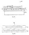
- FIG. 3Aillustrates a top electrode 302 and a bottom electrode 304 in accordance with an embodiment of the present invention.
- the top electrode 302may be formed, for example, by a self-aligned “lift-off” process wherein the top electrode 302 is deposited on the patterned photoresist layer 204 and the unwanted layer material of the photoresist layer 204 and the electrode material are then removed.
- FIG. 3Bis a flowchart illustrating a method 600 of forming the top electrode 302 using the self-aligned “lift-off” process.
- the method 600includes a step 610 , in which an electrode material is deposited on a patterned photoresist layer, for example the patterned photoresist layer 204 of FIG. 3A .
- the method 600proceeds with a step 620 , in which the unwanted layer material of the photoresist layer and the electrode material are removed.
- the top electrode 302is formed by the remaining electrode material after the step 620 is performed.
- the top electrode 302provides an electrical connection to the upper LED layer 114
- the bottom electrode 304provides an electrical connection to the lower LED layer 110 .
- the bottom electrode 304is preferably an ohmic contact formed of one or more layers of a metal or metal alloy, such as an alloy containing Ti/Al, Ti/Au, or the like.
- the top electrode 302makes ohmic contact with the p-type upper LED layer 114 and may be formed of one or more layers of a metal or metal alloy, such as an alloy containing Ni/Au or the like.
- the top electrode 302is positioned above the CBL 202 . Without the CBL 202 , the current flowing from the top electrode 302 through the light-emitting layer 112 to the lower LED layer 110 is a substantially direct route. As a result, much of the light emitted by the light-emitting layer 112 is blocked by the top electrode 302 , greatly reducing the light-emitting efficiency of the LED device.
- the top electrode 302By placing the top electrode 302 above the CBL 202 , the current that would normally flow along the most direct route between the top electrode 302 and the lower LED layer 110 is forced around the CBL 202 as indicated by the dotted lines of FIG. 3A . As the current flows between the upper LED layer 114 and the lower LED layer 110 , the light emitted by the light-emitting layer 112 is not substantially blocked by the top electrode 302 .
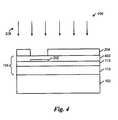
- FIGS. 4 and 5illustrate a method of forming an LED device 400 in accordance with another embodiment of the present invention.
- FIG. 4comprises substantially the same layers and may be formed using similar processes and materials as the LED device 100 discussed above with reference to FIGS. 1 and 2 , except that the upper LED layer ( 114 in FIGS. 1-3 ) is replaced by a first upper LED layer 402 .
- the first upper LED layer 402 of FIG. 4is formed having a thickness less than the desired final thickness of the upper LED layer 114 of FIGS. 1-3 .
- the implant process used to form the CBL 202may damage the surface of the upper LED layer 114 . It has also been found that the formation and removal of the photoresist layer 204 may also damage the surface of the upper LED layer 114 . In some cases the damage to the surface of the upper LED layer 114 may adversely affect the formation of and the electrical contact with overlying layers, such as the top electrode 302 , and possibly adversely affect the performance and reliability of the LED device.
- the upper LED layer 114is formed to have a thickness less than a desired thickness, as illustrated by the first upper LED layer 402 of FIG. 4 .
- the CBL 202is formed in the first upper LED layer 402 by implanting magnesium ions as illustrated by arrows 208 .
- the CBL 202may be formed in a similar manner as discussed above with reference to FIG. 2 .
- An activation annealmay be performed before or after formation of the CBL 202 .
- FIG. 5illustrates the LED device 400 after a second upper LED layer 502 is formed over the first upper LED layer 402 in accordance with an embodiment of the present invention.
- the second upper LED layer 502may be formed of the same materials using similar processes as those used for the first upper LED layer 402 .
- the second upper LED layer 502is formed to a thickness such that the combined thickness of the first upper LED layer 402 and the second upper LED layer 502 is about 1000 ⁇ to about 3000 ⁇ , but the second upper LED layer 502 preferably has a thickness of about 300 ⁇ to about 2700 ⁇ .
- processesmay be performed to complete the LED device 400 .
- the operation to the LED device 400is similar to the operation of the LED device 100 discussed above with reference to FIG. 3A .
Landscapes
- Led Devices (AREA)
Abstract
Description
Claims (17)
Priority Applications (5)
| Application Number | Priority Date | Filing Date | Title |
|---|---|---|---|
| US12/539,757US8399273B2 (en) | 2008-08-18 | 2009-08-12 | Light-emitting diode with current-spreading region |
| TW098127687ATWI517431B (en) | 2008-08-18 | 2009-08-18 | Method of forming a light emitting diode device |
| CN200910166790.XACN101656287B (en) | 2008-08-18 | 2009-08-18 | Light emitting diode device and method of forming the same |
| US13/793,198US8823049B2 (en) | 2008-08-18 | 2013-03-11 | Light-emitting diode with current-spreading region |
| US14/472,495US20150053918A1 (en) | 2008-08-18 | 2014-08-29 | Light-emitting diode with current-spreading region |
Applications Claiming Priority (2)
| Application Number | Priority Date | Filing Date | Title |
|---|---|---|---|
| US8982308P | 2008-08-18 | 2008-08-18 | |
| US12/539,757US8399273B2 (en) | 2008-08-18 | 2009-08-12 | Light-emitting diode with current-spreading region |
Related Child Applications (1)
| Application Number | Title | Priority Date | Filing Date |
|---|---|---|---|
| US13/793,198DivisionUS8823049B2 (en) | 2008-08-18 | 2013-03-11 | Light-emitting diode with current-spreading region |
Publications (2)
| Publication Number | Publication Date |
|---|---|
| US20100038674A1 US20100038674A1 (en) | 2010-02-18 |
| US8399273B2true US8399273B2 (en) | 2013-03-19 |
Family
ID=41680687
Family Applications (3)
| Application Number | Title | Priority Date | Filing Date |
|---|---|---|---|
| US12/539,757Expired - Fee RelatedUS8399273B2 (en) | 2008-08-18 | 2009-08-12 | Light-emitting diode with current-spreading region |
| US13/793,198ActiveUS8823049B2 (en) | 2008-08-18 | 2013-03-11 | Light-emitting diode with current-spreading region |
| US14/472,495AbandonedUS20150053918A1 (en) | 2008-08-18 | 2014-08-29 | Light-emitting diode with current-spreading region |
Family Applications After (2)
| Application Number | Title | Priority Date | Filing Date |
|---|---|---|---|
| US13/793,198ActiveUS8823049B2 (en) | 2008-08-18 | 2013-03-11 | Light-emitting diode with current-spreading region |
| US14/472,495AbandonedUS20150053918A1 (en) | 2008-08-18 | 2014-08-29 | Light-emitting diode with current-spreading region |
Country Status (3)
| Country | Link |
|---|---|
| US (3) | US8399273B2 (en) |
| CN (1) | CN101656287B (en) |
| TW (1) | TWI517431B (en) |
Families Citing this family (14)
| Publication number | Priority date | Publication date | Assignee | Title |
|---|---|---|---|---|
| US8399273B2 (en)* | 2008-08-18 | 2013-03-19 | Tsmc Solid State Lighting Ltd. | Light-emitting diode with current-spreading region |
| US8597962B2 (en)* | 2010-03-31 | 2013-12-03 | Varian Semiconductor Equipment Associates, Inc. | Vertical structure LED current spreading by implanted regions |
| US8507940B2 (en) | 2010-04-05 | 2013-08-13 | Taiwan Semiconductor Manufacturing Company, Ltd. | Heat dissipation by through silicon plugs |
| US8476649B2 (en) | 2010-12-16 | 2013-07-02 | Micron Technology, Inc. | Solid state lighting devices with accessible electrodes and methods of manufacturing |
| CN102290503B (en)* | 2011-08-24 | 2013-05-29 | 上海蓝光科技有限公司 | Light emitting diode and manufacturing method thereof |
| US20130221320A1 (en)* | 2012-02-27 | 2013-08-29 | Tsmc Solid State Lighting Ltd. | Led with embedded doped current blocking layer |
| US9312432B2 (en) | 2012-03-13 | 2016-04-12 | Tsmc Solid State Lighting Ltd. | Growing an improved P-GaN layer of an LED through pressure ramping |
| KR102007402B1 (en)* | 2012-08-06 | 2019-08-05 | 엘지이노텍 주식회사 | Light emitting device |
| CN103078026A (en)* | 2012-10-11 | 2013-05-01 | 光达光电设备科技(嘉兴)有限公司 | Semiconductor light-emitting component and manufacturing method thereof |
| CN103117344B (en)* | 2013-02-05 | 2016-08-24 | 海迪科(南通)光电科技有限公司 | LED and preparation method thereof |
| KR101517995B1 (en)* | 2013-03-29 | 2015-05-07 | 경희대학교 산학협력단 | Light Emitting Device Light-Amplified with Graphene and method for Fabricating the same |
| TWI572057B (en)* | 2014-11-07 | 2017-02-21 | A current blocking structure of a light emitting diode | |
| KR102733562B1 (en) | 2018-12-03 | 2024-11-25 | 삼성전자주식회사 | Display device |
| CN115274953B (en)* | 2022-06-20 | 2025-08-19 | 京东方华灿光电(浙江)有限公司 | Light-emitting diode chip for improving light efficiency and preparation method thereof |
Citations (38)
| Publication number | Priority date | Publication date | Assignee | Title |
|---|---|---|---|---|
| US5391917A (en) | 1993-05-10 | 1995-02-21 | International Business Machines Corporation | Multiprocessor module packaging |
| US5510298A (en) | 1991-09-12 | 1996-04-23 | Texas Instruments Incorporated | Method of interconnect in an integrated circuit |
| US5550391A (en)* | 1993-06-18 | 1996-08-27 | Ricoh Company, Ltd. | Light-emitting diode and light-emitting diode array |
| US5767001A (en) | 1993-05-05 | 1998-06-16 | Siemens Aktiengesellschaft | Process for producing semiconductor components between which contact is made vertically |
| JPH11186607A (en) | 1997-12-25 | 1999-07-09 | Showa Denko Kk | Compound semiconductor light emitting device |
| US5998292A (en) | 1997-11-12 | 1999-12-07 | International Business Machines Corporation | Method for making three dimensional circuit integration |
| US6184060B1 (en) | 1996-10-29 | 2001-02-06 | Trusi Technologies Llc | Integrated circuits and methods for their fabrication |
| US6322903B1 (en) | 1999-12-06 | 2001-11-27 | Tru-Si Technologies, Inc. | Package of integrated circuits and vertical integration |
| US6448168B1 (en) | 1997-09-30 | 2002-09-10 | Intel Corporation | Method for distributing a clock on the silicon backside of an integrated circuit |
| US6465892B1 (en) | 1999-04-13 | 2002-10-15 | Oki Electric Industry Co., Ltd. | Interconnect structure for stacked semiconductor device |
| US6531328B1 (en) | 2001-10-11 | 2003-03-11 | Solidlite Corporation | Packaging of light-emitting diode |
| US6538333B2 (en) | 2000-06-16 | 2003-03-25 | Chartered Semiconductor Manufacturing Ltd. | Three dimensional IC package module |
| US6599778B2 (en) | 2001-12-19 | 2003-07-29 | International Business Machines Corporation | Chip and wafer integration process using vertical connections |
| US6664129B2 (en) | 1996-10-29 | 2003-12-16 | Tri-Si Technologies, Inc. | Integrated circuits and methods for their fabrication |
| US6800930B2 (en) | 2002-07-31 | 2004-10-05 | Micron Technology, Inc. | Semiconductor dice having back side redistribution layer accessed using through-silicon vias, and assemblies |
| US6841883B1 (en) | 2003-03-31 | 2005-01-11 | Micron Technology, Inc. | Multi-dice chip scale semiconductor components and wafer level methods of fabrication |
| US20050093428A1 (en)* | 2003-10-30 | 2005-05-05 | Sharp Kabushiki Kaisha | Semiconductor light-emitting device |
| US6924551B2 (en) | 2003-05-28 | 2005-08-02 | Intel Corporation | Through silicon via, folded flex microelectronic package |
| US6962872B2 (en) | 2002-12-09 | 2005-11-08 | International Business Machines Corporation | High density chip carrier with integrated passive devices |
| US20050280022A1 (en)* | 2004-06-21 | 2005-12-22 | Matsushita Electric Industrial Co., Ltd. | Semiconductor laser device and manufacturing method thereof |
| US7049170B2 (en) | 2003-12-17 | 2006-05-23 | Tru-Si Technologies, Inc. | Integrated circuits and packaging substrates with cavities, and attachment methods including insertion of protruding contact pads into cavities |
| US7060601B2 (en) | 2003-12-17 | 2006-06-13 | Tru-Si Technologies, Inc. | Packaging substrates for integrated circuits and soldering methods |
| US7071546B2 (en) | 2002-01-16 | 2006-07-04 | Alfred E. Mann Foundation For Scientific Research | Space-saving packaging of electronic circuits |
| US7111149B2 (en) | 2003-07-07 | 2006-09-19 | Intel Corporation | Method and apparatus for generating a device ID for stacked devices |
| US7122912B2 (en) | 2004-01-28 | 2006-10-17 | Nec Electronics Corporation | Chip and multi-chip semiconductor device using thereof and method for manufacturing same |
| US7157787B2 (en) | 2002-02-20 | 2007-01-02 | Intel Corporation | Process of vertically stacking multiple wafers supporting different active integrated circuit (IC) devices |
| US7193308B2 (en) | 2003-09-26 | 2007-03-20 | Seiko Epson Corporation | Intermediate chip module, semiconductor device, circuit board, and electronic device |
| US20070108452A1 (en)* | 2005-11-17 | 2007-05-17 | Matthias Kauer | Growth of a semiconductor layer structure |
| US20070114545A1 (en) | 2005-11-23 | 2007-05-24 | Samsung Electro-Mechanics Co., Ltd. | Vertical gallium-nitride based light emitting diode |
| US7247565B2 (en) | 2003-12-31 | 2007-07-24 | Dongbu Electronics, Co., Ltd. | Methods for fabricating a copper interconnect |
| US7262495B2 (en) | 2004-10-07 | 2007-08-28 | Hewlett-Packard Development Company, L.P. | 3D interconnect with protruding contacts |
| US7271021B2 (en)* | 2003-10-17 | 2007-09-18 | Atomic Energy Council-Institute Of Nuclear Energy Research | Light-emitting device with a current blocking structure and method for making the same |
| US7297574B2 (en) | 2005-06-17 | 2007-11-20 | Infineon Technologies Ag | Multi-chip device and method for producing a multi-chip device |
| US7335972B2 (en) | 2003-11-13 | 2008-02-26 | Sandia Corporation | Heterogeneously integrated microsystem-on-a-chip |
| US20080111139A1 (en) | 2006-11-14 | 2008-05-15 | Samsung Electro-Mechanics Company Ltd. | Vertical light emitting device and method of manufacturing the same |
| US7582496B2 (en) | 2005-03-30 | 2009-09-01 | Samsung Electro-Mechanics Co., Ltd. | LED package using Si substrate and fabricating method thereof |
| US7619296B2 (en) | 2005-02-03 | 2009-11-17 | Nec Electronics Corporation | Circuit board and semiconductor device |
| US20110241040A1 (en) | 2010-04-05 | 2011-10-06 | Taiwan Semiconductor Manufacturing Company, Ltd. | Novel semiconductor package with through silicon vias |
Family Cites Families (3)
| Publication number | Priority date | Publication date | Assignee | Title |
|---|---|---|---|---|
| JP3622200B2 (en)* | 2001-07-02 | 2005-02-23 | ソニー株式会社 | Nitride semiconductor manufacturing method and semiconductor device manufacturing method |
| JP2003218776A (en)* | 2002-01-23 | 2003-07-31 | Hitachi Ltd | Mobile information terminal and information distribution method |
| US8399273B2 (en)* | 2008-08-18 | 2013-03-19 | Tsmc Solid State Lighting Ltd. | Light-emitting diode with current-spreading region |
- 2009
- 2009-08-12USUS12/539,757patent/US8399273B2/ennot_activeExpired - Fee Related
- 2009-08-18TWTW098127687Apatent/TWI517431B/enactive
- 2009-08-18CNCN200910166790.XApatent/CN101656287B/ennot_activeExpired - Fee Related
- 2013
- 2013-03-11USUS13/793,198patent/US8823049B2/enactiveActive
- 2014
- 2014-08-29USUS14/472,495patent/US20150053918A1/ennot_activeAbandoned
Patent Citations (46)
| Publication number | Priority date | Publication date | Assignee | Title |
|---|---|---|---|---|
| US5510298A (en) | 1991-09-12 | 1996-04-23 | Texas Instruments Incorporated | Method of interconnect in an integrated circuit |
| US5767001A (en) | 1993-05-05 | 1998-06-16 | Siemens Aktiengesellschaft | Process for producing semiconductor components between which contact is made vertically |
| US5391917A (en) | 1993-05-10 | 1995-02-21 | International Business Machines Corporation | Multiprocessor module packaging |
| US5550391A (en)* | 1993-06-18 | 1996-08-27 | Ricoh Company, Ltd. | Light-emitting diode and light-emitting diode array |
| US6664129B2 (en) | 1996-10-29 | 2003-12-16 | Tri-Si Technologies, Inc. | Integrated circuits and methods for their fabrication |
| US6639303B2 (en) | 1996-10-29 | 2003-10-28 | Tru-Si Technolgies, Inc. | Integrated circuits and methods for their fabrication |
| US6184060B1 (en) | 1996-10-29 | 2001-02-06 | Trusi Technologies Llc | Integrated circuits and methods for their fabrication |
| US6740582B2 (en) | 1996-10-29 | 2004-05-25 | Tru-Si Technologies, Inc. | Integrated circuits and methods for their fabrication |
| US6882030B2 (en) | 1996-10-29 | 2005-04-19 | Tru-Si Technologies, Inc. | Integrated circuit structures with a conductor formed in a through hole in a semiconductor substrate and protruding from a surface of the substrate |
| US6448168B1 (en) | 1997-09-30 | 2002-09-10 | Intel Corporation | Method for distributing a clock on the silicon backside of an integrated circuit |
| US5998292A (en) | 1997-11-12 | 1999-12-07 | International Business Machines Corporation | Method for making three dimensional circuit integration |
| JPH11186607A (en) | 1997-12-25 | 1999-07-09 | Showa Denko Kk | Compound semiconductor light emitting device |
| US6472293B2 (en) | 1999-04-13 | 2002-10-29 | Oki Electric Industry Co., Ltd. | Method for manufacturing an interconnect structure for stacked semiconductor device |
| US6465892B1 (en) | 1999-04-13 | 2002-10-15 | Oki Electric Industry Co., Ltd. | Interconnect structure for stacked semiconductor device |
| US6693361B1 (en) | 1999-12-06 | 2004-02-17 | Tru-Si Technologies, Inc. | Packaging of integrated circuits and vertical integration |
| US6322903B1 (en) | 1999-12-06 | 2001-11-27 | Tru-Si Technologies, Inc. | Package of integrated circuits and vertical integration |
| US6538333B2 (en) | 2000-06-16 | 2003-03-25 | Chartered Semiconductor Manufacturing Ltd. | Three dimensional IC package module |
| US6531328B1 (en) | 2001-10-11 | 2003-03-11 | Solidlite Corporation | Packaging of light-emitting diode |
| US6599778B2 (en) | 2001-12-19 | 2003-07-29 | International Business Machines Corporation | Chip and wafer integration process using vertical connections |
| US7071546B2 (en) | 2002-01-16 | 2006-07-04 | Alfred E. Mann Foundation For Scientific Research | Space-saving packaging of electronic circuits |
| US7157787B2 (en) | 2002-02-20 | 2007-01-02 | Intel Corporation | Process of vertically stacking multiple wafers supporting different active integrated circuit (IC) devices |
| US6800930B2 (en) | 2002-07-31 | 2004-10-05 | Micron Technology, Inc. | Semiconductor dice having back side redistribution layer accessed using through-silicon vias, and assemblies |
| US7355273B2 (en) | 2002-07-31 | 2008-04-08 | Micron Technology, Inc. | Semiconductor dice having back side redistribution layer accessed using through-silicon vias, methods |
| US6962867B2 (en) | 2002-07-31 | 2005-11-08 | Microntechnology, Inc. | Methods of fabrication of semiconductor dice having back side redistribution layer accessed using through-silicon vias and assemblies thereof |
| US6962872B2 (en) | 2002-12-09 | 2005-11-08 | International Business Machines Corporation | High density chip carrier with integrated passive devices |
| US7030481B2 (en) | 2002-12-09 | 2006-04-18 | Internation Business Machines Corporation | High density chip carrier with integrated passive devices |
| US6841883B1 (en) | 2003-03-31 | 2005-01-11 | Micron Technology, Inc. | Multi-dice chip scale semiconductor components and wafer level methods of fabrication |
| US6924551B2 (en) | 2003-05-28 | 2005-08-02 | Intel Corporation | Through silicon via, folded flex microelectronic package |
| US7111149B2 (en) | 2003-07-07 | 2006-09-19 | Intel Corporation | Method and apparatus for generating a device ID for stacked devices |
| US7193308B2 (en) | 2003-09-26 | 2007-03-20 | Seiko Epson Corporation | Intermediate chip module, semiconductor device, circuit board, and electronic device |
| US7271021B2 (en)* | 2003-10-17 | 2007-09-18 | Atomic Energy Council-Institute Of Nuclear Energy Research | Light-emitting device with a current blocking structure and method for making the same |
| US20050093428A1 (en)* | 2003-10-30 | 2005-05-05 | Sharp Kabushiki Kaisha | Semiconductor light-emitting device |
| US7335972B2 (en) | 2003-11-13 | 2008-02-26 | Sandia Corporation | Heterogeneously integrated microsystem-on-a-chip |
| US7060601B2 (en) | 2003-12-17 | 2006-06-13 | Tru-Si Technologies, Inc. | Packaging substrates for integrated circuits and soldering methods |
| US7049170B2 (en) | 2003-12-17 | 2006-05-23 | Tru-Si Technologies, Inc. | Integrated circuits and packaging substrates with cavities, and attachment methods including insertion of protruding contact pads into cavities |
| US7247565B2 (en) | 2003-12-31 | 2007-07-24 | Dongbu Electronics, Co., Ltd. | Methods for fabricating a copper interconnect |
| US7122912B2 (en) | 2004-01-28 | 2006-10-17 | Nec Electronics Corporation | Chip and multi-chip semiconductor device using thereof and method for manufacturing same |
| US20050280022A1 (en)* | 2004-06-21 | 2005-12-22 | Matsushita Electric Industrial Co., Ltd. | Semiconductor laser device and manufacturing method thereof |
| US7262495B2 (en) | 2004-10-07 | 2007-08-28 | Hewlett-Packard Development Company, L.P. | 3D interconnect with protruding contacts |
| US7619296B2 (en) | 2005-02-03 | 2009-11-17 | Nec Electronics Corporation | Circuit board and semiconductor device |
| US7582496B2 (en) | 2005-03-30 | 2009-09-01 | Samsung Electro-Mechanics Co., Ltd. | LED package using Si substrate and fabricating method thereof |
| US7297574B2 (en) | 2005-06-17 | 2007-11-20 | Infineon Technologies Ag | Multi-chip device and method for producing a multi-chip device |
| US20070108452A1 (en)* | 2005-11-17 | 2007-05-17 | Matthias Kauer | Growth of a semiconductor layer structure |
| US20070114545A1 (en) | 2005-11-23 | 2007-05-24 | Samsung Electro-Mechanics Co., Ltd. | Vertical gallium-nitride based light emitting diode |
| US20080111139A1 (en) | 2006-11-14 | 2008-05-15 | Samsung Electro-Mechanics Company Ltd. | Vertical light emitting device and method of manufacturing the same |
| US20110241040A1 (en) | 2010-04-05 | 2011-10-06 | Taiwan Semiconductor Manufacturing Company, Ltd. | Novel semiconductor package with through silicon vias |
Non-Patent Citations (5)
| Title |
|---|
| Chang, S.J., et al., "Nitride-Based LEDs with an Insulating SiO2 Layer Underneath p-Pad Electrodes," Electrochemical and Solid-State Letters, vol. 10, No. 6, 2007, pp. H175-H177. |
| Chinese Patent Office, Office Action dated Sep. 1, 2010, Application No. 200910166790.x, 6 pages. |
| Chowdhury, S., et al., "Enhancement and Depletion Mode AlGaN/GaN CAVET With Mg-Ion-Implanted GaN as Current Blocking Layer," IEEE Electron Device Letters, vol. 29, No. 6, Jun. 2008, pp. 543-545. |
| Huh, C., et al., "Improvement in light-output efficiency of InGaN/GaN multiple-quantum well light-emitting diodes by current blocking layer," Journal of Applied Physics, vol. 92, No. 5, Sep. 1, 2002, pp. 2248-2250. |
| US Patent Office, unpublished U.S. Appl. No. 13/405,906, filed Feb. 7, 2012, 32 pages. |
Also Published As
| Publication number | Publication date |
|---|---|
| US20100038674A1 (en) | 2010-02-18 |
| US20150053918A1 (en) | 2015-02-26 |
| US20130264539A1 (en) | 2013-10-10 |
| US8823049B2 (en) | 2014-09-02 |
| CN101656287A (en) | 2010-02-24 |
| TW201010145A (en) | 2010-03-01 |
| TWI517431B (en) | 2016-01-11 |
| CN101656287B (en) | 2012-08-29 |
Similar Documents
| Publication | Publication Date | Title |
|---|---|---|
| US8399273B2 (en) | Light-emitting diode with current-spreading region | |
| US6614060B1 (en) | Light emitting diodes with asymmetric resonance tunnelling | |
| US8354663B2 (en) | Micro-pixel ultraviolet light emitting diode | |
| US9136432B2 (en) | High efficiency light emitting diode | |
| KR100969131B1 (en) | Method for fabricating of light emitting device | |
| KR101707118B1 (en) | Light emitting diode and method for fabricating the light emitting device | |
| US8659033B2 (en) | Light-emitting diode with textured substrate | |
| KR101134731B1 (en) | Light emitting device and method for fabricating the same | |
| KR101537330B1 (en) | Method of manufacturing nitride semiconductor light emitting device | |
| KR101813935B1 (en) | Light emitting device | |
| KR20110124337A (en) | III-nitride light emitting device containing boron | |
| US9543467B2 (en) | Light emitting device | |
| KR20110052131A (en) | Light emitting device and manufacturing method | |
| US10177274B2 (en) | Red light emitting diode and lighting device | |
| KR20130058406A (en) | Semiconductor light emitting device | |
| KR101719623B1 (en) | Light emitting diode | |
| US8148732B2 (en) | Carbon-containing semiconductor substrate | |
| KR20130103070A (en) | Semiconductor light emitting device | |
| US20090272975A1 (en) | Poly-Crystalline Layer Structure for Light-Emitting Diodes | |
| KR100728132B1 (en) | Light Emitting Diode Using Current Diffusion Layer | |
| KR100986327B1 (en) | Light emitting device and method for fabricating the same | |
| KR101295468B1 (en) | Light emitting device and method of fabricating the same | |
| KR20160027644A (en) | Light emitting device and lighting system | |
| KR101874873B1 (en) | Light-emitting device | |
| KR101755670B1 (en) | Light emitting device and method for fabricating light emitting device |
Legal Events
| Date | Code | Title | Description |
|---|---|---|---|
| AS | Assignment | Owner name:TAIWAN SEMICONDUCTOR MANUFACTURING COMPANY, LTD.,T Free format text:ASSIGNMENT OF ASSIGNORS INTEREST;ASSIGNORS:CHEN, DING-YUAN;YU, CHEN-HUA;CHIOU, WEN-CHIH;REEL/FRAME:023289/0355 Effective date:20090806 Owner name:TAIWAN SEMICONDUCTOR MANUFACTURING COMPANY, LTD., Free format text:ASSIGNMENT OF ASSIGNORS INTEREST;ASSIGNORS:CHEN, DING-YUAN;YU, CHEN-HUA;CHIOU, WEN-CHIH;REEL/FRAME:023289/0355 Effective date:20090806 | |
| AS | Assignment | Owner name:TSMC SOLID STATE LIGHTING LTD., TAIWAN Free format text:ASSIGNMENT OF ASSIGNORS INTEREST;ASSIGNOR:TAIWAN SEMICONDUCTOR MANUFACTURING COMPANY LTD.;REEL/FRAME:027856/0711 Effective date:20120301 | |
| STCF | Information on status: patent grant | Free format text:PATENTED CASE | |
| AS | Assignment | Owner name:EPISTAR CORPORATION, TAIWAN Free format text:MERGER;ASSIGNOR:CHIP STAR LTD.;REEL/FRAME:037196/0816 Effective date:20150715 Owner name:CHIP STAR LTD., TAIWAN Free format text:CHANGE OF NAME;ASSIGNOR:TSMC SOLID STATE LIGHTING LTD.;REEL/FRAME:037211/0130 Effective date:20150402 | |
| FPAY | Fee payment | Year of fee payment:4 | |
| MAFP | Maintenance fee payment | Free format text:PAYMENT OF MAINTENANCE FEE, 8TH YEAR, LARGE ENTITY (ORIGINAL EVENT CODE: M1552); ENTITY STATUS OF PATENT OWNER: LARGE ENTITY Year of fee payment:8 | |
| FEPP | Fee payment procedure | Free format text:MAINTENANCE FEE REMINDER MAILED (ORIGINAL EVENT CODE: REM.); ENTITY STATUS OF PATENT OWNER: LARGE ENTITY | |
| LAPS | Lapse for failure to pay maintenance fees | Free format text:PATENT EXPIRED FOR FAILURE TO PAY MAINTENANCE FEES (ORIGINAL EVENT CODE: EXP.); ENTITY STATUS OF PATENT OWNER: LARGE ENTITY | |
| STCH | Information on status: patent discontinuation | Free format text:PATENT EXPIRED DUE TO NONPAYMENT OF MAINTENANCE FEES UNDER 37 CFR 1.362 | |
| FP | Lapsed due to failure to pay maintenance fee | Effective date:20250319 |