US8398693B2 - Electrically actuated medical devices - Google Patents
Electrically actuated medical devicesDownload PDFInfo
- Publication number
- US8398693B2 US8398693B2US10/763,825US76382504AUS8398693B2US 8398693 B2US8398693 B2US 8398693B2US 76382504 AUS76382504 AUS 76382504AUS 8398693 B2US8398693 B2US 8398693B2
- Authority
- US
- United States
- Prior art keywords
- electrically actuated
- balloon
- catheter
- lumen
- actuated members
- Prior art date
- Legal status (The legal status is an assumption and is not a legal conclusion. Google has not performed a legal analysis and makes no representation as to the accuracy of the status listed.)
- Expired - Fee Related, expires
Links
- XILGXSYEQPUUEW-UHFFFAOYSA-N[H]N1C(C)=CC=C1C1=CC=C(C2=CC=C(C3=CC=C(C4=CC=C(C5=CC=C(C6=CC=C(C7=CC=C(C)N7[H])N6[H])N5[H])N4[H])N3[H])N2[H])N1[H]Chemical compound[H]N1C(C)=CC=C1C1=CC=C(C2=CC=C(C3=CC=C(C4=CC=C(C5=CC=C(C6=CC=C(C7=CC=C(C)N7[H])N6[H])N5[H])N4[H])N3[H])N2[H])N1[H]XILGXSYEQPUUEW-UHFFFAOYSA-N0.000description1
Images


Classifications
- A—HUMAN NECESSITIES
- A61—MEDICAL OR VETERINARY SCIENCE; HYGIENE
- A61F—FILTERS IMPLANTABLE INTO BLOOD VESSELS; PROSTHESES; DEVICES PROVIDING PATENCY TO, OR PREVENTING COLLAPSING OF, TUBULAR STRUCTURES OF THE BODY, e.g. STENTS; ORTHOPAEDIC, NURSING OR CONTRACEPTIVE DEVICES; FOMENTATION; TREATMENT OR PROTECTION OF EYES OR EARS; BANDAGES, DRESSINGS OR ABSORBENT PADS; FIRST-AID KITS
- A61F2/00—Filters implantable into blood vessels; Prostheses, i.e. artificial substitutes or replacements for parts of the body; Appliances for connecting them with the body; Devices providing patency to, or preventing collapsing of, tubular structures of the body, e.g. stents
- A61F2/95—Instruments specially adapted for placement or removal of stents or stent-grafts
- A61F2/958—Inflatable balloons for placing stents or stent-grafts
- A—HUMAN NECESSITIES
- A61—MEDICAL OR VETERINARY SCIENCE; HYGIENE
- A61B—DIAGNOSIS; SURGERY; IDENTIFICATION
- A61B17/00—Surgical instruments, devices or methods
- A61B17/12—Surgical instruments, devices or methods for ligaturing or otherwise compressing tubular parts of the body, e.g. blood vessels or umbilical cord
- A61B17/12022—Occluding by internal devices, e.g. balloons or releasable wires
- A61B17/12131—Occluding by internal devices, e.g. balloons or releasable wires characterised by the type of occluding device
- A61B17/1214—Coils or wires
- A—HUMAN NECESSITIES
- A61—MEDICAL OR VETERINARY SCIENCE; HYGIENE
- A61B—DIAGNOSIS; SURGERY; IDENTIFICATION
- A61B17/00—Surgical instruments, devices or methods
- A61B17/32—Surgical cutting instruments
- A61B17/3205—Excision instruments
- A61B17/3207—Atherectomy devices working by cutting or abrading; Similar devices specially adapted for non-vascular obstructions
- A61B17/320725—Atherectomy devices working by cutting or abrading; Similar devices specially adapted for non-vascular obstructions with radially expandable cutting or abrading elements
- A—HUMAN NECESSITIES
- A61—MEDICAL OR VETERINARY SCIENCE; HYGIENE
- A61B—DIAGNOSIS; SURGERY; IDENTIFICATION
- A61B17/00—Surgical instruments, devices or methods
- A61B2017/00367—Details of actuation of instruments, e.g. relations between pushing buttons, or the like, and activation of the tool, working tip, or the like
- A61B2017/00398—Details of actuation of instruments, e.g. relations between pushing buttons, or the like, and activation of the tool, working tip, or the like using powered actuators, e.g. stepper motors, solenoids
- A—HUMAN NECESSITIES
- A61—MEDICAL OR VETERINARY SCIENCE; HYGIENE
- A61B—DIAGNOSIS; SURGERY; IDENTIFICATION
- A61B17/00—Surgical instruments, devices or methods
- A61B2017/00831—Material properties
- A61B2017/00867—Material properties shape memory effect
- A61B2017/00871—Material properties shape memory effect polymeric
- A—HUMAN NECESSITIES
- A61—MEDICAL OR VETERINARY SCIENCE; HYGIENE
- A61B—DIAGNOSIS; SURGERY; IDENTIFICATION
- A61B17/00—Surgical instruments, devices or methods
- A61B17/22—Implements for squeezing-off ulcers or the like on inner organs of the body; Implements for scraping-out cavities of body organs, e.g. bones; for invasive removal or destruction of calculus using mechanical vibrations; for removing obstructions in blood vessels, not otherwise provided for
- A61B2017/22051—Implements for squeezing-off ulcers or the like on inner organs of the body; Implements for scraping-out cavities of body organs, e.g. bones; for invasive removal or destruction of calculus using mechanical vibrations; for removing obstructions in blood vessels, not otherwise provided for with an inflatable part, e.g. balloon, for positioning, blocking, or immobilisation
- A61B2017/22061—Implements for squeezing-off ulcers or the like on inner organs of the body; Implements for scraping-out cavities of body organs, e.g. bones; for invasive removal or destruction of calculus using mechanical vibrations; for removing obstructions in blood vessels, not otherwise provided for with an inflatable part, e.g. balloon, for positioning, blocking, or immobilisation for spreading elements apart
- A—HUMAN NECESSITIES
- A61—MEDICAL OR VETERINARY SCIENCE; HYGIENE
- A61F—FILTERS IMPLANTABLE INTO BLOOD VESSELS; PROSTHESES; DEVICES PROVIDING PATENCY TO, OR PREVENTING COLLAPSING OF, TUBULAR STRUCTURES OF THE BODY, e.g. STENTS; ORTHOPAEDIC, NURSING OR CONTRACEPTIVE DEVICES; FOMENTATION; TREATMENT OR PROTECTION OF EYES OR EARS; BANDAGES, DRESSINGS OR ABSORBENT PADS; FIRST-AID KITS
- A61F2/00—Filters implantable into blood vessels; Prostheses, i.e. artificial substitutes or replacements for parts of the body; Appliances for connecting them with the body; Devices providing patency to, or preventing collapsing of, tubular structures of the body, e.g. stents
- A61F2/95—Instruments specially adapted for placement or removal of stents or stent-grafts
- A61F2/962—Instruments specially adapted for placement or removal of stents or stent-grafts having an outer sleeve
- A—HUMAN NECESSITIES
- A61—MEDICAL OR VETERINARY SCIENCE; HYGIENE
- A61M—DEVICES FOR INTRODUCING MEDIA INTO, OR ONTO, THE BODY; DEVICES FOR TRANSDUCING BODY MEDIA OR FOR TAKING MEDIA FROM THE BODY; DEVICES FOR PRODUCING OR ENDING SLEEP OR STUPOR
- A61M25/00—Catheters; Hollow probes
- A61M25/0043—Catheters; Hollow probes characterised by structural features
- A61M2025/0058—Catheters; Hollow probes characterised by structural features having an electroactive polymer material, e.g. for steering purposes, for control of flexibility, for locking, for opening or closing
- A—HUMAN NECESSITIES
- A61—MEDICAL OR VETERINARY SCIENCE; HYGIENE
- A61M—DEVICES FOR INTRODUCING MEDIA INTO, OR ONTO, THE BODY; DEVICES FOR TRANSDUCING BODY MEDIA OR FOR TAKING MEDIA FROM THE BODY; DEVICES FOR PRODUCING OR ENDING SLEEP OR STUPOR
- A61M25/00—Catheters; Hollow probes
- A61M25/0043—Catheters; Hollow probes characterised by structural features
- A61M25/0054—Catheters; Hollow probes characterised by structural features with regions for increasing flexibility
- A—HUMAN NECESSITIES
- A61—MEDICAL OR VETERINARY SCIENCE; HYGIENE
- A61M—DEVICES FOR INTRODUCING MEDIA INTO, OR ONTO, THE BODY; DEVICES FOR TRANSDUCING BODY MEDIA OR FOR TAKING MEDIA FROM THE BODY; DEVICES FOR PRODUCING OR ENDING SLEEP OR STUPOR
- A61M25/00—Catheters; Hollow probes
- A61M25/01—Introducing, guiding, advancing, emplacing or holding catheters
- A61M25/0105—Steering means as part of the catheter or advancing means; Markers for positioning
- A61M25/0133—Tip steering devices
- A61M25/0158—Tip steering devices with magnetic or electrical means, e.g. by using piezo materials, electroactive polymers, magnetic materials or by heating of shape memory materials
- A—HUMAN NECESSITIES
- A61—MEDICAL OR VETERINARY SCIENCE; HYGIENE
- A61N—ELECTROTHERAPY; MAGNETOTHERAPY; RADIATION THERAPY; ULTRASOUND THERAPY
- A61N1/00—Electrotherapy; Circuits therefor
- A61N1/18—Applying electric currents by contact electrodes
- A61N1/20—Applying electric currents by contact electrodes continuous direct currents
Definitions
- This inventionrelates to medical devices for implantation or insertion into the body, and more particularly to medical devices such as catheters, guidewires, and aneurysm coils, in which electrically actuated materials, such as electroactive polymers and piezoelectric materials, are used to enhance or expand their functionality.
- Proceduresare presently known for treatment of a variety of vascular conditions, including treatment of vascular obstructions and enlargements.
- a guide catheteris introduced into the cardiovascular system of a patient and advanced through the aorta until the distal end of the catheter is in the ostium of the designated coronary artery.
- a guidewireis then advanced through the guide catheter and across the site to be treated in the coronary artery.
- a balloon catheteris then advanced over the guidewire to the treatment site, and at which point the balloon is expanded to reopen the artery.
- a physiciancan implant an intravascular prosthesis, for example, a stent, inside the artery at the treatment site.
- an intravascular prosthesisfor example, a stent
- the arterial obstructionis so extensive that the physician has difficulty advancing the various medical devices past the obstruction.
- current balloon catheterscan be described as having a hydraulic actuating mechanism. Because hydraulic systems are more efficient at larger dimensions, the present trend to downscale device sizes has created the need for actuators that efficiently function at very small diameters.
- the physicianmay have to withdraw a stent (or other prosthesis) that has tracked in an artery, during which time the edge of the stent may catch on a lesion or guiding catheter and be at risk for embolization.
- GDCsGuglilmi detachable coils
- the delivery wireWhen the coil is properly positioned within the aneurysm, a small current is applied to the delivery wire, dissolving the same at a position proximal to the platinum coil by means of electrolysis. Once electrolysis occurs, the delivery wire can be removed leaving the coil in place. Another coil can then be introduced. The process is continued until the aneurysm is densely packed with coils and no longer opacifies during diagnostic contrast injections. In general, the more tightly the coils are wound, the more densely the aneurysm is packed. There is a continuing need in the art for materials that will provide such coils.
- a medical devicewhich comprises the following: (a) an elongate body adapted for insertion into a body lumen of a patient (typically a mammalian subject, and more typically a human subject); and (b) an active region comprising a conductive polymer (for instance, polypyrrole), wherein the active region is disposed over the elongate body such that the medical device is expanded in at least one radial dimension (relative to the axis of the elongate body) upon volumetric expansion of the active region.
- a elongate bodyadapted for insertion into a body lumen of a patient (typically a mammalian subject, and more typically a human subject); and (b) an active region comprising a conductive polymer (for instance, polypyrrole), wherein the active region is disposed over the elongate body such that the medical device is expanded in at least one radial dimension (relative to the axis of the elongate body) upon volumetric expansion of the active region
- the active region(or regions) directly expands the device in a radial direction. In other embodiments, the active region(s) indirectly expand the device by causing a passive deformable region to radially expand upon volumetric expansion of the active region.
- the active region(s) of the devicecan be provided in a wide range of configurations.
- an active regioncan surround the elongate body in the form of a circumferential band.
- an active regioncan be provided in the form of a longitudinal strip.
- an active regioncan be provided, which increases in radius as one travels in a distal-to-proximal direction, for example, gradually or in a step-wise fashion.
- the active regionis disposed in a recess that is formed in the elongate body, for instance, in a circumferential recess or in a longitudinal recess.
- the active regionis provided at a distal end of a catheter or guidewire, in which case the distal end may be flattened, for example, to improve the device's ability to negotiate body lumen obstructions.
- the active region(s)are configured such that at least a portion of the length of the medical device is stiffened upon expansion of the active region(s). For example, this feature can be provided by circumferentially surrounding the elongate body with one or more active regions.
- the medical devicecomprises a cutting blade that is adapted to engage the tissue of a surrounding lumen after insertion of the device and expansion of the active region.
- cutting bladesinclude metal cutting blades and diamond-tipped cutting blades.
- the cutting bladecan be provided in a sheath, where desired.
- a medical devicecomprising: (a) an elongate body adapted for insertion into a body lumen; (b) a balloon; and (c) an active region comprising an electroactive polymer (for instance, polypyrrole), wherein the active region is adapted to radially advance at least a portion of the balloon when the balloon is in a substantially uninflated state.
- an electroactive polymerfor instance, polypyrrole
- the active regionis adapted to radially advance at least the proximal portion of balloon; in others, at least the proximal and distal portions of the balloon are advanced; in still others, the proximal, central and distal portions of the balloon are advanced.
- At least a portion of the balloonis radially advanced by the direct volumetric expansion of the active region. In others, at least a portion of the balloon is radially advanced by a passive deformable region that radially expands upon the volumetric expansion of the active region.
- the medical devicecomprises a curvilinear member, and the active region is adapted to radially expand the curvilinear member.
- the curvilinear membercan be a spiral member, which can originate from and wrap around the elongate member of the catheter.
- the spiral membercan comprise, for example, an active layer disposed over a conductive layer, typically a metal.
- a medical devicee.g., a balloon catheter, an arotic graft, a vena cava filter or a stent, such as a coronary vascular stent, peripheral vascular stent, a renal stent or a biliary stent, among many other devices
- a medical devicewhich comprises: (a) an insertable body adapted for insertion into a body lumen of a patient; (b) a device lumen within the insertable body; and (c) one or more electrically actuated members disposed along at least a portion of the length of the device lumen.
- the one or more electrically actuated members in this aspect of the inventionare adapted to transform at least a portion of the length of the device lumen between an expanded state and a contracted state, in which state the insertable body is more readily inserted into the body lumen of the patient.
- the one or more electrically actuated membersextend along the entire length of the device lumen, while in others they extend along only a portion of the length (for instance, the insertable length) of the device lumen.
- an aneurysm filler coilwhich comprises: (a) an elongate conductive region (for instance, a metal such as gold or platinum); and (b) an active region comprising an electroactive polymer (for instance, polypyrrole).
- the active region and the conductive regionare typically disposed relative to one another such that the device becomes more tightly coiled upon being disconnected from a source of electrical potential.
- the active regionis longitudinally disposed along the length of the elongate conductive region.
- the active regioncan be disposed along one side of the conductive region, or it can form a spiral around the conductive region.
- An advantage of the above aspects of the present inventionis that medical devices can be provided, which have enhanced properties for advancement within body lumens, even in the face of near total obstructions.
- Another advantage of the present inventionis that medical devices can be provided in which hydraulic expansion mechanisms are replaced or supplemented, thereby allowing these devices to operate efficiently at very small diameters.
- a further advantage of the present inventionis that medical devices can be provided that have improved ability to retrieve stents or other prosthesis from a body lumen, with reduced risk of embolization.
- Yet another advantage of the present inventionis that aneurysm coils can be provided, which are able to coil more tightly upon being positioned within an aneurism.
- FIGS. 1A to 1Care schematic, partial (above axis only), longitudinal cross-sectional views of a catheter in accordance with an embodiment of the present invention.
- FIGS. 2A and 2Bare schematic, partial, longitudinal cross-sectional views of a catheter in accordance with another embodiment of the present invention.
- FIGS. 3A and 3Bare schematic, partial cross-sectional views illustrating radial expansion via passive members, in accordance with two embodiments of the present invention.
- FIG. 4Ais a schematic, partial, longitudinal cross-sectional view of a catheter in accordance with another embodiment of the present invention.
- FIG. 4Bis a schematic, radial cross-sectional view of the catheter of FIG. 4A , taken at the position indicated by line a-a′ in FIG. 4A .
- FIGS. 5A and 5Bare schematic, partial, longitudinal cross-sectional views of a catheter in accordance with another embodiment of the present invention.
- FIGS. 6-8are schematic, partial, longitudinal cross-sectional views of catheters in accordance with various additional embodiments of the present invention.
- FIG. 9Ais a schematic, partial, longitudinal cross-sectional view of a guidewire in accordance with an embodiment of the present invention.
- FIG. 9Bis a schematic, radial cross-sectional view of the guidewire of FIG. 9A , taken at a position indicated by line a-a′ in FIG. 9A .
- FIGS. 10A and 10Bare schematic, radial cross-sectional views of the guidewire of FIG. 9A , taken at a position indicated by line a-a′ in FIG. 9A , in accordance with two alternate embodiments of the present invention.
- FIG. 11Ais a schematic, partial, longitudinal cross-sectional view of a guidewire in accordance with another embodiment of the present invention.
- FIG. 11Bis a schematic, radial cross-sectional view of the guidewire of FIG. 11A , taken at a position indicated by line a-a′ in FIG. 11A .
- FIG. 12is a schematic, partial, longitudinal cross-sectional view of an aneurysm coil in accordance with an embodiment of the present invention.
- FIGS. 13A and 13Bare schematic, cross-sectional views of a balloon catheter shaft in expanded and contracted states, respectively, in accordance with an embodiment of the present invention.
- FIGS. 14A and 14Bare schematic perspective views of the electrically actuatable member from the device of FIGS. 13A and 13B in uncurled and curled states, respectively, in accordance with an embodiment of the present invention.
- FIGS. 15A and 15Bare schematic top views of electrically actuatable members, in accordance with an embodiment of the present invention.
- FIG. 15Cis a schematic top view of a collection of electrically actuatable members, in accordance with an embodiment of the present invention.
- FIGS. 16A and 16Bare schematic, cross-sectional views of a balloon catheter shaft in expanded and contracted states, respectively, in accordance with an embodiment of the present invention.
- FIGS. 17A and 17Bare schematic, cross-sectional views of a balloon catheter shaft in expanded and contracted states, respectively, in accordance with another embodiment of the present invention.
- FIGS. 18 and 19are schematic perspective views of stents, in accordance with two embodiments of the present invention.
- FIGS. 20A and 20Bare schematic, partial, longitudinal views of an assembly that is adapted to radially expand a plurality of cutting blades, in accordance with an embodiment of the present invention.
- FIGS. 21A and 21Bare schematic, partial, longitudinal views of an assembly that is adapted to radially expand a plurality of cutting blades, in accordance with another embodiment of the present invention.
- FIGS. 22A-22C , 23 A-B and 24 A-Bare schematic, partial longitudinal views of lumens or shafts, in accordance with various embodiments of the present invention.
- FIG. 25is a schematic, partial, longitudinal, cross-sectional view of a catheter in accordance with yet another embodiment of the present invention.
- the medical devices of the present inventionare actuated, at least in part, using electroactive polymer (EAP) actuators.
- Electroactive polymersare polymers characterized by their ability to change shape in response to electrical stimulation.
- the electroactive polymers that are typically used in connection with the present inventionare ionic EAPs, more typically conductive EAPs that feature a conjugated backbone (e.g., they have a backbone that comprises and alternating series of single and double carbon-carbon bonds) and have the ability to increase electrical conductivity under oxidation or reduction.
- Some commonly known EAPsare polypyrroles, polyanilines, polythiophenes, polyethylenedioxythiophenes, poly(p-phenylene vinylene)s, polysulfones and polyacetylenes.
- Polypyrrolewhich is one of the most stable of these polymers under physiological conditions, is pictured below:
- EAPsare typically semi-conductors in their pure form. However, upon oxidation or reduction of the polymer, the electrical conductivity is understood to be changed from a semi-conductive regime to a semi-metallic regime. Such oxidation and reduction are believed to lead to a charge imbalance that, in turn, results in a flow of ions into or out of the material. These ions typically enter/exit the material from/into an ionically conductive electrolyte medium associated with the electroactive polymer.
- Ionic EAPsalso have a number of additional properties that make them attractive for use in the devices of the present invention, including the following: (a) they are lightweight, flexible, small and easily manufactured; (b) energy sources are available which are easy to control, and energy can be easily delivered to the EAPS; (c) small changes in potential (e.g., potential changes on the order of 1V) can be used to effect volume change in the EAPs; (d) they are relatively fast in actuation (e.g., full expansion/contraction in a few seconds); (e) EAP regions can be created using a variety of techniques, for example, electrodeposition; and (f) EAP regions can be patterned, for example, using photolithography, if desired.
- energy sourcesare available which are easy to control, and energy can be easily delivered to the EAPS
- small changes in potentiale.g., potential changes on the order of 1V
- EAP regionscan be created using a variety of techniques, for example, electrodeposition
- EAP regionscan be patterned, for example, using
- the following elementsare generally utilized to bring about electroactive polymer actuation: (a) a source of electrical potential, (b) an active region, which comprises the electroactive polymer, (c) a counter electrode and (d) an electrolyte in contact with both the active region and the counter electrode.
- the electrolytewhich is in contact with at least a portion of the surface of the active region, allows for the flow of ions and thus acts as a source/sink for the ions.
- the electrolytemay be, for example, a liquid, a gel, or a solid, so long as ion movement is permitted.
- the electrolyteis a liquid, it may be, for example, an aqueous solution containing a salt, for example, an NaCl solution, a KCl solution, a sodium dodecylbenzene sulfonate solution, a phosphate buffered solution, physiological fluid, and so forth.
- the electrolyteis a gel
- itmay be, for example, a salt-containing agar gel or polymethylmethacrylate (PMMA) gel.
- PMMApolymethylmethacrylate
- the electrolyteis a solid, it may be, for example, a polymer electrolyte.
- the counter electrodemay be formed from any suitable electrical conductor, for example, a conducting polymer, a conducting gel, or a metal, such as stainless steel, gold or platinum. At least a portion of the surface of the counter electrode is generally in contact with the electrolyte, in order to provide a return path for charge.
- the EAP-containing active regioncontracts or expands in response to the flow of ions out of, or into, the same.
- any electroactive polymer that exhibits contractile or expansile propertiesmay be used in connection with the various active regions of the invention, including those listed above.
- the active regionis a polypyrrole-containing active region.
- Polypyrrole-containing active regionscan be fabricated using a number of known techniques, for example, extrusion, casting, dip coating, spin coating, or electro-polymerization/deposition techniques. Polypyrrole-containing active regions can also be patterned, for example, using lithographic techniques, if desired.
- polypyrrolecan be galvanostatically deposited on a platinised substrate from a pyrrole monomer solution using the procedures described in D. Zhou et al., “Actuators for the Cochlear Implant,” Synthetic Metals 135-136 (2003) 39-40. Polypyrrole can also be deposited on gold. In some embodiments, adhesion of the electrodeposited polypyrrole layer is enhanced by covering a metal such as gold with a chemisorbed layer of molecules that can be copolymerized into the polymer layer with chemical bonding. Thiol is one example of a head group for strong chemisorbtion to metal.
- the tail groupshould be chemically similar to the pyrrole monomer, so the use of a pyrrole ring attached to the thiol group (e.g., via a short alkyl chain) is a natural choice.
- Specific examples of such moleculesare 1-(2-thioethyl)-pyrrole and 3-(2-thioethyl)-pyrrole. See, e.g., E. Smela et al., “Thiol Modified Pyrrole Monomers: 1.
- the active regioncomprises polypyrrole (PPy) doped with dodecylbenzene sulfonate (DBS) anions.
- DBSdodecylbenzene sulfonate
- the cationsWhen placed in contact with an electrolyte containing small mobile cations, for example, Na + cations, and when a current is passed between the polypyrrole-containing active region and a counter electrode, the cations are inserted/removed upon reduction/oxidation of the polymer, leading to expansion/contraction of the same.
- This processcan be represented by the following equation: PPy + (DBS ⁇ )+Na + +e ⁇ PPy o (Na + DBS ⁇ ) where Na + represents a sodium ion, e ⁇ represents an electron, PPy + represents the oxidized state of the polypyrrole, PPy o represents the reduced state of the polymer, and species are enclosed in parentheses to indicate that they are incorporated into the polymer.
- the sodium ionsare supplied by the electrolyte that is in contact with the electroactive polymer member. Specifically, when the EAP is oxidized, the positive charges on the backbone are at least partially compensated by the DBS ⁇ anions present within the polymer.
- the source of electrical potential for use in connection with the present inventioncan be quite simple, consisting, for example, of a dc battery and an on/off switch. Alternatively, more complex systems can be utilized. For example, an electrical link can be established with a microprocessor, allowing a complex set of control signals to be sent to the EAP-containing active region(s).
- EAP-containing active regionscan be provided that either expand or contract when an applied voltage of appropriate value is interrupted depending, for example, upon the selection of the EAP, dopant, and electrolyte.
- EAP actuatorstheir design considerations, and the materials and components that may be employed therein, can be found, for example, in E. W. H. Jager, E. Smela, O. Inganas, “Microfabricating Conjugated Polymer Actuators,” Science, 290, 1540-1545, 2000; E. Smela, M. Kallenbach, and J. Holdenried, “Electrochemically Driven Polypyrrole Bilayers for Moving and Positioning Bulk Micromachined Silicon Plates,” J. Microelectromechanical Systems, 8(4), 373-383, 1999; U.S. Pat. No. 6,249,076, assigned to Massachusetts Institute of Technology, and Proceedings of the SPIE , Vol.
- the medical devices of the present inventionare actuated, at least in part, using materials involving piezoelectric, electrostrictive, and/or Maxwell stresses.
- medical devicescomprise an elongate body, which is adapted for insertion into a body lumen.
- An active region that comprises a conductive polymeris disposed over the elongate body such that the medical device is expanded in at least one radial dimension (i.e., in at least one dimension that is orthogonal to the longitudinal axis of the device) upon volumetric expansion of the active region.
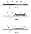
- FIG. 1Ais a schematic illustration of a balloon catheter 100 , which can be used, for example, to expand a stent (not illustrated) at a site of arterial obstruction.
- distal portions of the catheter 100are to the right, while proximal portions are to the left.
- the axis of the catheter(which also corresponds to the axis of the body lumen, e.g., artery, into which the catheter is inserted) is designated by the letter “x”.
- Proximal and distal markerse.g., radiographic markers
- 115 p , 115 dare provided within the catheter as is known in the art, to assist in placing the catheter at an appropriate position within the body lumen.
- the balloon catheterincludes an inner lumen 110 (or a shaft, as the case may be) and a balloon 130 .
- the balloon 130can be provided with cutting blades, as is known in the art.
- Disposed between the inner lumen 110 and the balloon 130is an active region 120 , which contains an electroactive polymer.
- the active region 120can be provided in various configurations. For example, in the embodiment illustrated in FIG. 1A , the active region 120 is provided in a band around the inner lumen 110 .
- multiple actuators in various configurationsfor example, a series of longitudinal strips, a series of circumferential bands, a series patches, and so forth
- the active region 120is provided in a recess formed in the inner lumen 110 . Although this is not required, by providing the active region 120 within a recess, an increase in the inserted profile of the device will be minimized, if not avoided entirely.
- a contact electrode(not shown), for example, one formed of gold (Au), can be provided between the inner lumen 110 and the active region 120 , to actuate the active region 120 .
- the inner lumen 110is not formed of a conductive material and therefore cannot function as an electrode.
- the counter electrode functioncan be performed, for example, by a separate dedicated conductive member (not shown) within the device 100 .
- a conductive element of the device 100 itselfcan be used for this purpose. In any case, care is generally taken to avoid electrically shorting the active region (or its electrode) with the counter electrode.
- An electrolyte(not separately illustrated) can be provided, for example, within a sealed structure that also encloses the active region and counter electrode. If desired, the balloon 130 can serve this function. In other embodiments, physiological fluid can serve as the electrolyte.
- the devicewill operate as follows: When a positive potential is applied to the gold electrode contact, electrons are removed from the PPy, and it is oxidized from its neutral state (PPy o ) to its oxidized state (PPy + ). This is a reversible process. Thus, the PPy can be reduced from its oxidized state back to its neutral state by adding electrons.
- the PPyis doped with DBS ⁇ (dodecylbenzenesulfonate) anions and the device is operated in an electrolyte solution, for example, an NaDBS solution.
- the EAP-containing active region 120radially expands the balloon (and any associated prosthesis, such as a stent) outward from a fully crimped state. As the balloon's diameter is increased, the balloon enters into a more efficient operating range, where less pressure is required to generate the large strains that are afforded by hydraulic actuation of this type. The balloon is then expanded as illustrated in FIG. 1C .
- the first actuatori.e., the EAP-containing active region 120
- improves the efficiency of the second actuatori.e., the balloon 130 ).
- the balloonis deflated, and the above-described process is reversed (i.e., the PPy is oxidized, expelling the Na + ions from the active region 120 and shrinking the same).
- the device 100is withdrawn from the body lumen, completing the procedure.
- FIG. 25illustrates a balloon catheter 100 in accordance with another embodiment of the invention.
- the balloon catheter 100 of FIG. 25like that of FIG. 1A , includes an inner lumen/shaft 110 and a balloon 130 .
- the balloon catheter 100 of FIG. 25does not contain proximal and distal markers that are distinct from the active region. Instead, the balloon catheter 100 of FIG. 25 contains active regions 120 a and 120 b , which are positioned beneath the balloon 130 near the proximal and distal ends of the same.
- active regions 120 a and 120 bare deposited onto metal regions 123 a and 123 b (e.g., gold or platinum bands) using techniques such as those discussed above.
- metal regions 123 a and 123 bare also radio-opaque, allowing them to serve as proximal and distal radiographic markers.
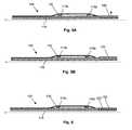
- FIG. 2Aillustrates a balloon catheter 100 , which like FIG. 1A , includes an inner lumen 110 , proximal and distal markers 115 p , 115 d , active region 120 , and balloon 130 .
- the device of FIG. 2Afurther includes a fixed member 125 and an elastic passive member 150 , which can be, for example, a member formed from rubber or a rubber-like elastic material.
- FIG. 2AComparing FIG. 2A with FIG. 2B , it can be seen that upon expansion of the active region 120 , the proximal marker 115 p (which is slidable along lumen 110 in this embodiment) is forced to the right, compressing passive member 150 against the distal marker 115 d (which is fixed in this embodiment). Being constrained in this fashion, the passive member 150 radially expands to engage the balloon 130 , with the attendant advantages discussed above in connection with FIGS. 1A-1C . In contrast to the device of FIGS. 1A-1C , which provides high stress but low strain, the embodiment of FIGS. 2A-2B can provide the reverse, if the ratio L 1 /L 2 is large enough.
- FIGS. 3A and 3Billustrate fixed proximal and distal markers 115 p , 115 d , active regions 120 and passive members 150 .
- the active regions 120compress the passive member 150 from both the distal and proximal ends of the device, radially expanding the passive member 150 .
- a central active region 120compresses proximal and distal passive members 150 , radially expanding the same.
- FIG. 4Ashows a schematic longitudinal cross-sectional view of the distal portion of a balloon catheter 100
- FIG. 4Bshows a schematic radial cross-sectional view of the balloon catheter 100 of FIG. 4A , taken at the position of line a-a′.
- Balloon catheter 100includes an inner lumen 110 (or shaft) and a balloon 130 .
- a stent 160is positioned over the balloon 130 .
- Beneath the balloon 130are two EAP-containing actuators 121 , which are provided in the shape of a planar coil, as seen more clearly in FIG. 4B .
- the EAP-containing actuators 121are illustrated in their expanded state.
- the EAP-containing actuators 121can comprise, for example, a gold or platinum base onto which a polypyrrole-containing active layer is deposited.
- An electrolyte and counter electrode(not shown) can be provided, for example, as previously discussed. Depending upon whether the active layer is deposited on the outside or the inside of the coil, the coil will either tighten (and thus radially contract) or loosen (and thus radially expand) upon expansion of the active layer, and vice versa.
- a physicianmay be forced to withdraw a stent (or other prosthesis) that has tracked in an artery, during which time the edge of the stent may catch at risk of embolization.
- the catheter 100by providing the catheter 100 with EAP-containing actuators 121 , for example, at the proximal end, at the distal end, or at both (as illustrated), the balloon 130 can be pushed beyond the radius of the stent 160 to reduce this risk.
- FIG. 5AYet another embodiment of the invention is illustrated in FIG. 5A .
- the catheter apparatus 100 of FIG. 5Aincludes an inner lumen 110 (or shaft), proximal and distal markers 115 p , 115 d , and a balloon 130 .
- the active region 120is provided at the distal tip of the catheter apparatus 100 , rather than beneath the balloon 130 .
- FIG. 5Billustrates the device of FIG. 5A upon expansion of the EAP-containing active region 120 .
- this device 100can be used, for example, to widen vascular obstructions, allowing the device 100 to be properly positioned relative to the obstruction.
- the surrounding physiological fluid(not illustrated) is used as a source/sink for the small ions which enter/exit the active region 120 during oxidation/reduction of the electroactive polymer.
- a counter electrode(not illustrated) is also typically contacted with the physiological fluid in these embodiments, completing the current path.
- a guidewire(not illustrated) extending through the inner lumen 110 can be used for this purpose, so long as care is taken to prevent electrical shorting as discussed above.
- FIG. 6illustrates another embodiment of the invention, which is substantially like that of FIG. 5A , except that cutting blades 170 (one illustrated) are provided on the outside circumference of the active region 120 .
- the cutting bladescan be formed from a variety of materials, including metallic blades, for example, stainless steel blades, and diamond tipped blades (diamond blades are discussed, for example, in Ser. No. 10/212,508 entitled “Tubular cutting process and system”).
- the blade illustratedextends longitudinally, a variety of configurations are possible, including various configurations known in the cutting balloon art, such as segmented, notched and spiral configurations.
- the cutting bladescan be retracted into a protective sheath prior to use.
- the bladescan be sheathed within a soft deformable or flowable polymer. Upon expansion of the active region, the deformable or flowable polymer is compressed, allowing the blades to engage adjacent tissue.
- the catheter 100can be provided with a series active regions 120 a , 120 b , 120 c , which are of progressively larger outer radius (i.e., they are disposed in a telescoping or stepped arrangement) as one proceeds proximally from the distal tip of the catheter as illustrated in FIG. 7 .
- a similar effectcan be achieved by utilizing an active region 120 of gradually increasing outer radius as illustrated in FIG. 8 .
- the underlying lumen 110can also be stepped or graded in this fashion.
- apparatuslike those described in connection with FIGS. 5A , 5 B, 6 , 7 and 8 are provided, but without a balloon and/or with a central solid shaft, rather than a lumen.
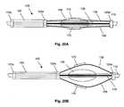
- FIGS. 20A and 20Billustrate an assembly 105 , which is slidable over an inner lumen (or a solid shaft such as a guidewire) 110 .
- the assembly 100includes a proximal ring 125 p and a distal ring 125 d , which are axially spaced at a fixed distance from one another by stiff elongated structural member 135 (e.g., a rigid strip or a rod).
- An active region 120is disposed between the proximal ring 125 p and slidable ring 125 s , whose distance from the proximal ring 125 p (and the distal ring 125 d ) is not fixed.
- the assembly 105further includes deformable members such as flexible members 138 (e.g., flexible wires), which are attached at the proximal end to ring 125 s and at the distal end to distal ring 125 d .
- Cutting blades 170are attached to outer surfaces of flexible members 138 .
- Cutting blades 170 and a portion of flexible members 138are disposed in depressions (e.g., slits, not shown) within a polymer body 136 (e.g., a polymer ball, which as illustrated is partially transparent).
- a polymer body 136e.g., a polymer ball, which as illustrated is partially transparent.
- the slidable ring 125 sis pushed toward the distal end of the device, relative to proximal and distal rings 125 p , 125 d . Consequently, the flexible members 138 , which are disposed between slidable ring 125 s and the distal ring 125 d , are pushed out through the slits in the protective polymer ball 136 , along with the cutting blades 170 attached thereto. Sliding the assembly 105 in actuated form will slice through surrounding tissue, such as an artery wall.
- FIGS. 21A and 21BAnother embodiment of the invention is illustrated in FIGS. 21A and 21B .
- the mechanism of engagement of the cutting knives 170 in this embodimentis similar to that of FIGS. 20A-20B , with the active region 120 pushing a slidable ring 125 s toward the distal end of the device, resulting in the outward movement of flexible members 138 .
- the knives 170emerge from slots 134 s that are formed in a surrounding catheter tube 134 , which is illustrated in cross-section in FIGS. 21A and 21B .
- proximal and distal rings 125 p , 125 dare axially spaced apart by a structural member 135 in FIGS. 20A-20B .
- the distal and proximal rings 125 d and 125 pare not movable relative to the member 110 (e.g., a core wire), but are rather fixed to the member 110 , eliminating the need for a structural member 135 to keep the rings 125 d , 125 p axially spaced apart.
- the flexible members 138are fixed to the central core wire 110 via the distal ring 125 d , while the active member 120 is fixed to the core wire 110 via the proximal ring 125 p.
- Cutting bladescan be deployed from guidewires, such as those to follow, using schemes analogous to those described above.
- a composite guidewire 200is illustrated therein, which comprises a guidewire core 210 having an active coating 220 .
- the guidewire core 210can be any of a variety of guidewire structures known in the art.
- the active coating 220 provided over the guidewire core 210comprises an electroactive polymer, for example, a polypyrrole polymer as described above.
- a gold or platinum layer(not shown) is deposited on the guidewire core 210 , in this particular embodiment to act as an electrode contact for the overlying active coating 220 .
- an electrolytecan be provided within a self-contained structure, or the surrounding physiological fluid can be used as a source/sink for the ions which enter/exit the active coating during operation.
- the thickness as well as the stiffness of the composite guidewire 200can be varied. Increasing the thickness of the guidewire 200 is useful for expanding obstructions as previously discussed. Increasing the stiffness of the guidewire 200 will improve the practitioner's ability to push the guidewire through obstructions. Because the stiffness of this type of structure is predicted to change with the fourth power of the outer dimension, any change in the outer layer thickness should have a significant effect on stiffness.
- FIG. 9Bis a schematic cross-sectional view taken across the guidewire 200 at the position indicated by line a-a′ in FIG. 9A , and illustrates a cylindrical guidewire core 210 with an annular active coating 220 of even thickness.
- the guidewire core 210is flattened, for example, as illustrated in the radial cross-sections of FIGS. 10A and 10B .
- Guidewires with flattened tipsare described, for example, in U.S. Pat. No. 4,830,023 to de Toledo et al. By flattening at least the tip of the guidewire 200 , the ability to penetrate obstructions is improved.
- the guidewire core 210need not be completely surrounded by the active coating 220 , as illustrated in FIG. 10B .
- the ability to penetrate and expand obstructionsis further improved by providing the guidewire with stepped or graded regions like those described above in connection with FIGS. 7 and 8 .
- An active coating 220 like that described in FIGS. 9A and 9B abovecan be provided, for example, over the entire guidewire core 210 , over only a distal portion (e.g., the tip) of the guidewire core 210 , and so forth.
- a number of active coating regions 220can be utilized, for example, as a series of longitudinal strips (not illustrated) or a series of circumferential bands as illustrated in FIGS. 11A and 11B .
- These active coating regions 220 a , 220 b , 220 ccan be operated as a group, or they can be operated individually by providing independent electrical connections to each, thereby allowing the degree of stiffness and expansion of the guidewire 200 to be varied along its length.
- FIG. 22Aillustrates a series active member rings 220 spaced along a lumen or shaft 210 .
- the spacing between the ringsallows the lumen/shaft 210 to bend readily.
- FIG. 22Cupon longitudinal expansion of the rings 220 , the gaps between the rings 220 are reduced (or eliminated) thereby constraining the degree to which the lumen/shaft 210 can be bent without encountering resistance due to the rings 220 contacting one another.
- the active ringsengage regions of another material (e.g., a stiff material such as a metal or hard plastic).
- FIG. 23Aillustrates an active ring 220 and two stiff material rings 215 spaced along a lumen or shaft 210 .
- the spacing between the active ring 220 and the stiff material rings 215 in FIG. 23Aallows the lumen/shaft 210 to bend readily.
- bendingis restricted.
- FIG. 24Aillustrates two active rings 220 a , 220 b spaced along a lumen or shaft 210 .
- Three pins 215 formed from a stiff materialare embedded in one active ring 220 a , while slots for receiving the pins 215 are formed in the other active ring 220 b .
- the lumen/shaft 210is allowed to bend readily when the active ring 220 a , 220 b is in the contracted state as illustrated in FIG. 24A .
- the pins 215 embedded active ring 220 aengage the slots in active ring 220 b , restricting bending.
- FIGS. 13A and 13Bcontain cross-sectional views of a shaft for a balloon catheter 400 in expanded and contracted states, respectively.
- the balloon catheter shaft 400includes an elongate body 410 , which is provided with two lumens in this particular embodiment, a guidewire lumen 425 and an inflation lumen 420 .
- the elongate body 410is fabricated, for example, from a polymeric or other flexible material, via extrusion or another commercially suitable process known in the art.
- the balloon catheter shaft 400further comprises an electrically actuated member 430 , which is in this embodiment is in the form of an elongated strip that is disposed within an outer wall of the elongate body 410 .
- Electrically actuated members 430 for use in conjunction with this aspect of the present inventioninclude those constructed from electroactive polymers and from other materials which involve piezoelectric, electrostrictive or Maxwell stresses. Electroactive polymer actuators are discussed elsewhere herein. Piezoelectric and electrostrictive materials are materials that mechanically deform upon application of an external electric field and, conversely, that generate an electric charge when they are mechanically deformed. Such actuators may be structures of composite materials, layers of different materials (e.g., metal-insulator-metal structures) and innumerable other combinations.
- piezoelectric materialsinclude ceramic materials such as Lead Zirkonate Titanate PZT-5, Lead Titanate PT, Lead Metaniobate PbNb 2 O 6 , barium titanate and quartz, among others; metallic piezoelectric materials; polymer materials such as polyvinylidene fluoride (PVDF) and its copolymers with trifluoroethylene and tetrafluoroethylene, nylons with an odd number of carbons (e.g., PA 7), polyvinylchloride (PVC), polyphenylethernitrile (PPEN) and polyacrylonitrle (PAN), among others; as well as combinations thereof.
- PVDFpolyvinylidene fluoride
- PA 7polyvinylchloride
- PPENpolyphenylethernitrile
- PANpolyacrylonitrle
- Piezoelectric and electrostrictive actuatorsrequire an applied voltage, and current flow can be limited, allowing the application of necessary voltages without danger of serious injury to a patient.
- the electrically actuatable member 430 in FIGS. 13A-Bis changed between (a) an uncurled (expanded) state as illustrated in the schematic perspective view of FIG. 14A and (b) a curled (contracted) state as illustrated in the schematic perspective view of FIG. 14B .
- the electrically actuated member 430need not be perfectly planar in the less curled state, for example, the electrically actuated member 430 can change from a crescent shape to an inverted crescent shape, from a crescent shape to a circular shape, etc. Electrically actuated members can also be employed which change, for example, from a helical shape to a straight shape, from a circular ring shape to an ovaloid shape, and so forth.
- the inflation lumen 420is transformable between a contracted lumen state as illustrated in FIG. 13B and an expanded lumen state as illustrated in FIG. 13A .
- the cross-sectional area of the lumencan be expanded by at least 10%, 15%, 20%, 25%, 50%, 75%, 100% or more during the transition from the contracted lumen state to the expanded lumen state.
- the device 400is more readily inserted through the body lumen of a patient when in the contracted lumen state of FIG. 13B , as compared to the expanded lumen state of FIG. 13A .
- placing the lumen 420 in the contracted stateallows the balloon catheter shaft 400 to take on a reduced delivery profile, thereby enhancing the ability to insert and track the shaft 400 over a guide wire through a body lumen, such as a blood vessel.
- a body lumensuch as a blood vessel.
- the cross section of the inflation lumen 420is expanded/enlarged by changing the state of the electrically actuated member 430 that is disposed within the shaft 400 . This transformation allows the balloon to be efficiently inflated and also holds the inflation lumen 420 open during balloon deflation, at which point the lumen typically experiences negative pressures.
- the electroactive member 430 of FIG. 14Acan be provided with enhanced longitudinal flexibility by creating one or more regions of narrowed cross-section as illustrated, for example, in FIGS. 15A and 15B . Longitudinal flexibility can also be enhanced by replacing the electroactive member 430 of FIG. 14A with a series of electroactive members 430 , as illustrated in FIG. 15C .
- These electroactive members 430are electrically connected to one another by conductive members (not illustrated), for instance, metallic conductors, such as gold wires.
- FIGS. 16A and 16Bcontain cross-sectional views of a balloon catheter shaft 400 in expanded and contracted profiles, respectively.
- These figuresillustrate an inner wall 414 (i.e. an inner tubular member) defining an inner guidewire lumen 425 , and an outer wall 412 (i.e., an outer tubular member), which along with the inner wall 414 defines an annular outer inflation lumen 420 .
- the electrically actuated member 430 in FIGS. 16A and 16Bis in the form of an elongated strip, which is disposed within the outer wall 412 and which is electrically transformable from one degree of bending to another.
- the inflation lumen 420is transformed between an expanded lumen state in FIG. 16A and a contracted lumen state in FIG. 16B .
- the inner wall 414 and outer wall 412are beneficially fabricated, for example, from a polymer or other flexible material via extrusion or other commercially suitable processes known in the art.
- the fact that the inner and outer walls 414 , 412 are discreet componentsallows them to be readily constructed from different materials in some embodiments.
- the inner wall 414can be fabricated from a material that is stiffer than the material of the outer wall 412 . This arrangement resists binding between the guidewire (not illustrated) and the inner wall 414 during operation, while at the same time allowing the outer wall 412 to readily change shape under the influence of the electrically actuated member 430 .
- FIGS. 17A and 17BIn the cross sections illustrated in connection with the embodiments of FIGS. 13A , 13 B, 16 A and 16 B, only a single electrically actuated member 430 is present in radial cross-section. However, in various other embodiments, one, two, three, four, five, six seven, eight or more electrically actuated members are longitudinally disposed within the device 400 at a given cross-section.
- the embodiment of the invention illustrated in FIGS. 17A and 17Bemploys eight electrically actuated members 430 , which are disposed around the circumference of the outer wall 412 .
- the inflation lumen 420is transformed from an expanded lumen state in FIG. 17A to a contracted (or “crinkled”) lumen state in FIG. 17B , and vice versa.
- the electrically actuated member(s)are disposed along the entire length of the inflation lumen. In other embodiments, the electrically actuated member(s) are disposed along only a portion of the length of the inflation lumen. For instance, the electrically actuated member(s) may be disposed only along the insertable portions of the inflation lumen, or they may be disposed only along the distal portions of the inflation lumen that are required to pass through body lumens (e.g., blood vessels) of relatively small cross-section.
- body lumense.g., blood vessels
- the electrically actuated member(s)may be disposed along the complete/partial length of the inflation lumen in a variety of configurations, including straight down the complete/partial length of the inflation lumen, helically wound around the complete/partial length of the inflation lumen 420 , and so forth.
- the electrically actuated member(s) 430 in the embodiments of FIGS. 13A-B , 16 A-B and 17 A-Bare disposed within the outer wall of the device between the inflation lumen and the exterior of the device.
- the electrically actuated member(s)could just as readily be disposed on the inside surface or the outside surface of the outer wall.
- the deviceneed not be provided with a single inflation lumen as illustrated in FIGS. 13A-B , 16 A-B and 17 A-B and 17 B, but can also be provided with two inflation lumens, three inflation lumens, four inflation lumens, and so forth, either with or without a guidewire lumen.
- the above conceptsapply to essentially any device for which it is desirable to switch between a first cross-section of relatively reduced area and a second cross-section of relatively expanded area.
- the above conceptsare applicable to any number of additional devices, including stents, arotic grafts and vena cava filters, among devices.
- a stent 450is illustrated in FIG. 18 in accordance with an embodiment of the present invention.
- the electrically actuated members 430for use in this device include members based on electroactive polymer and piezoelectric materials.
- the electrically actuatable members 430 of FIGS. 18A and 18Bare electrically transformable between states having differing degrees of bending. As a result of the change in shape of the electrically actuated members 430 (and analogous to FIGS. 17A and 17B above), the stent 450 is transformable between an expanded state and a contracted state (not shown).
- the stent 450may be permanent or removable.
- a voltageis applied to the stent to place it in a reduced profile state.
- the electrically actuated membersare beneficially selected in this embodiment such that the stent is in a reduce profile state upon application of electrical potential and an expanded profile state when the potential is removed.
- a delivery sheath(not shown) may be placed over the stent while it is in a reduced profile state to keep it compressed, even if the voltage is removed. Subsequently, the stent is advanced through a body lumen of a patient using a catheter-type delivery system with appropriate electrical contacts for applying a voltage/current to the electrically actuated members.
- the sheathis retracted, if present, while a voltage is applied to the electrically actuated members 430 to maintain the stent 450 in a low profile state.
- the voltageis then removed to deploy (expand) the stent 450 within the body lumen, and the delivery system is retracted from the patient.
- the stent 450then remains in this expanded profile state in the patient unless and until a sufficient voltage is applied to the electrically actuated members (for example, in the event the stent is to be withdrawn from the patient).
- the electrically actuated members 430are disposed within a stent having solid tubular structure.
- a stent 450that contains a number of windows 455 (one numbered).
- four electrically actuated members 430are provided within the walls of the stent 450 , and the stent 450 is electrically transformable between a low profile state and an expanded profile state.
- the stents 450 of FIGS. 18 and 19contain four substantially rectangular, electrically actuated members 430 , like the balloon catheter shafts 400 above, these devices can include practically any number of electrically actuated members 430 in a wide variety of shapes.
- the electrically actuated members within the stents and balloon catheter shafts described abovecan be formed from various materials, including ceramic materials, metallic materials and polymeric materials.
- One advantage of metallic electrically actuated membersis that the members can be insert-molded (i.e. injection molded) within a polymer structure to form a stent or other tubular member without additional processing.
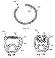
- FIG. 12is a schematic, cross-sectional view, taken along a portion of the length of an aneurysm filler coil device 300 .
- the device 300comprises an elongate coil member 310 and an elongate active region 320 , which comprises an electroactive polymer.
- the coil member 310 and the active region 320 in the embodiment illustratedare in the form of two elongated strips, forming a bilayer device.
- the active region 320upon insertion of the coil device 300 into an aneurysm, the active region 320 is contracted, further tightening the coil device 300 and allowing the packing density of the aneurysm to be increased.
- the coil member 310 of the device 300 of FIG. 12is a platinum member like those found in presently known aneurysm coils.
- the platinum coil member 320also acts as an electrode contact for the active region 320 of the device 300 .
- the active region 320is selected such that (a) when it is inserted into the body lumen while applying an appropriate potential, the active region 320 is in a expanded state, and (b) when the potential is discontinued (e.g., when the coil is separated from an associated catheter delivery device), the active region 320 shrinks, thereby tightening the coiling of the device 300 .
- a counter electrodecan be provided, for example, in connection with the catheter delivery device, and the surrounding physiological fluid can be used as a sink (electrolyte) for the small ions that exit the active region 320 during shrinkage.
- an alternative aneurysm filler coil devicecan be formed by wrapping a conductive coil member in a helical fashion with an active member.
- the coil devicecontains an active region that results in coil tightening upon expansion, rather than contraction.
Landscapes
- Health & Medical Sciences (AREA)
- Life Sciences & Earth Sciences (AREA)
- Engineering & Computer Science (AREA)
- Biomedical Technology (AREA)
- Surgery (AREA)
- Public Health (AREA)
- Heart & Thoracic Surgery (AREA)
- Vascular Medicine (AREA)
- Veterinary Medicine (AREA)
- Animal Behavior & Ethology (AREA)
- General Health & Medical Sciences (AREA)
- Oral & Maxillofacial Surgery (AREA)
- Transplantation (AREA)
- Reproductive Health (AREA)
- Nuclear Medicine, Radiotherapy & Molecular Imaging (AREA)
- Cardiology (AREA)
- Medical Informatics (AREA)
- Molecular Biology (AREA)
- Media Introduction/Drainage Providing Device (AREA)
- Materials For Medical Uses (AREA)
Abstract
Description

PPy+(DBS−)+Na++e−PPyo(Na+DBS−)
where Na+ represents a sodium ion, e− represents an electron, PPy+ represents the oxidized state of the polypyrrole, PPyorepresents the reduced state of the polymer, and species are enclosed in parentheses to indicate that they are incorporated into the polymer. In this case the sodium ions are supplied by the electrolyte that is in contact with the electroactive polymer member. Specifically, when the EAP is oxidized, the positive charges on the backbone are at least partially compensated by the DBS− anions present within the polymer. Upon reduction of the polymer, however, the immobile DBS− ions cannot exit the polymer to maintain charge neutrality, so the smaller, more mobile, Na+ ions enter the polymer, expanding the volume of the same. Upon re-oxidation, the Na+ ions again exit the polymer into the electrolyte, reducing the volume of the polymer. The source of electrical potential for use in connection with the present invention can be quite simple, consisting, for example, of a dc battery and an on/off switch. Alternatively, more complex systems can be utilized. For example, an electrical link can be established with a microprocessor, allowing a complex set of control signals to be sent to the EAP-containing active region(s).
Claims (7)
Priority Applications (5)
| Application Number | Priority Date | Filing Date | Title |
|---|---|---|---|
| US10/763,825US8398693B2 (en) | 2004-01-23 | 2004-01-23 | Electrically actuated medical devices |
| CA002554197ACA2554197A1 (en) | 2004-01-23 | 2005-01-21 | Electrically actuated medical devices |
| EP05711732AEP1708778A1 (en) | 2004-01-23 | 2005-01-21 | Electrically actuated medical devices |
| PCT/US2005/001854WO2005072809A1 (en) | 2004-01-23 | 2005-01-21 | Electrically actuated medical devices |
| JP2006551277AJP2007521871A (en) | 2004-01-23 | 2005-01-21 | Electrically operated medical device |
Applications Claiming Priority (1)
| Application Number | Priority Date | Filing Date | Title |
|---|---|---|---|
| US10/763,825US8398693B2 (en) | 2004-01-23 | 2004-01-23 | Electrically actuated medical devices |
Publications (2)
| Publication Number | Publication Date |
|---|---|
| US20050165439A1 US20050165439A1 (en) | 2005-07-28 |
| US8398693B2true US8398693B2 (en) | 2013-03-19 |
Family
ID=34795146
Family Applications (1)
| Application Number | Title | Priority Date | Filing Date |
|---|---|---|---|
| US10/763,825Expired - Fee RelatedUS8398693B2 (en) | 2004-01-23 | 2004-01-23 | Electrically actuated medical devices |
Country Status (5)
| Country | Link |
|---|---|
| US (1) | US8398693B2 (en) |
| EP (1) | EP1708778A1 (en) |
| JP (1) | JP2007521871A (en) |
| CA (1) | CA2554197A1 (en) |
| WO (1) | WO2005072809A1 (en) |
Cited By (7)
| Publication number | Priority date | Publication date | Assignee | Title |
|---|---|---|---|---|
| US20130095400A1 (en)* | 2010-06-18 | 2013-04-18 | Myfc Ab | Electrochemically actuated valve |
| US20140180089A1 (en)* | 2012-12-21 | 2014-06-26 | Volcano Corporation | System and method for guidewire control |
| US9147825B2 (en) | 2012-03-07 | 2015-09-29 | Board of Regents of the Nevada System of Higher Education on behalf of the University of Nevado, Reno | Methods of fabricating multi-degree of freedom shaped electroactive polymer actuators/sensors for catheters |
| US9370640B2 (en) | 2007-09-12 | 2016-06-21 | Novasentis, Inc. | Steerable medical guide wire device |
| US9833596B2 (en) | 2013-08-30 | 2017-12-05 | Novasentis, Inc. | Catheter having a steerable tip |
| US10603195B1 (en) | 2015-05-20 | 2020-03-31 | Paul Sherburne | Radial expansion and contraction features of medical devices |
| US20230277811A1 (en)* | 2006-06-28 | 2023-09-07 | Abbott Laboratories | Expandable introducer sheath to preserve guidewire access |
Families Citing this family (113)
| Publication number | Priority date | Publication date | Assignee | Title |
|---|---|---|---|---|
| US7484006B2 (en)* | 2002-02-22 | 2009-01-27 | Bea Systems, Inc. | System and method for server network configuration and addressing |
| US20040267348A1 (en) | 2003-04-11 | 2004-12-30 | Gunderson Richard C. | Medical device delivery systems |
| CA2526347C (en)* | 2003-05-20 | 2010-07-06 | The Cleveland Clinic Foundation | Apparatus and methods for repair of a cardiac valve |
| US20050113892A1 (en)* | 2003-11-26 | 2005-05-26 | Sproul Michael E. | Surgical tool with an electroactive polymer for use in a body |
| US7744619B2 (en) | 2004-02-24 | 2010-06-29 | Boston Scientific Scimed, Inc. | Rotatable catheter assembly |
| US7922740B2 (en) | 2004-02-24 | 2011-04-12 | Boston Scientific Scimed, Inc. | Rotatable catheter assembly |
| JP4091016B2 (en)* | 2004-04-22 | 2008-05-28 | オリンパス株式会社 | Endoscope system |
| US7989042B2 (en)* | 2004-11-24 | 2011-08-02 | Boston Scientific Scimed, Inc. | Medical devices with highly flexible coated hypotube |
| US7318838B2 (en)* | 2004-12-31 | 2008-01-15 | Boston Scientific Scimed, Inc. | Smart textile vascular graft |
| US7536225B2 (en)* | 2005-01-21 | 2009-05-19 | Ams Research Corporation | Endo-pelvic fascia penetrating heating systems and methods for incontinence treatment |
| US7462186B2 (en)* | 2005-05-03 | 2008-12-09 | Ethicon Endo-Surgery, Inc. | Anastomotic ring applier device utilizing an electroactive polymer |
| US20070027519A1 (en)* | 2005-07-28 | 2007-02-01 | Ethicon Endo-Surgery, Inc. | Devices and methods for stent deployment |
| US8133249B2 (en)* | 2005-07-28 | 2012-03-13 | Ethicon Endo-Surgery, Inc. | Devices and methods for stricture dilation |
| US7749197B2 (en) | 2005-07-28 | 2010-07-06 | Ethicon Endo-Surgery, Inc. | Electroactive polymer-based percutaneous endoscopy gastrostomy tube and methods of use |
| US20070032851A1 (en)* | 2005-08-02 | 2007-02-08 | Boston Scientific Scimed, Inc. | Protection by electroactive polymer sleeve |
| US7778684B2 (en)* | 2005-08-08 | 2010-08-17 | Boston Scientific Scimed, Inc. | MRI resonator system with stent implant |
| US7998132B2 (en) | 2005-09-02 | 2011-08-16 | Boston Scientific Scimed, Inc. | Adjustable stiffness catheter |
| US7452372B2 (en)* | 2005-09-22 | 2008-11-18 | Boston Scientific Scimed, Inc. | Bifurcated stent |
| US8211088B2 (en)* | 2005-10-14 | 2012-07-03 | Boston Scientific Scimed, Inc. | Catheter with controlled lumen recovery |
| US8876772B2 (en)* | 2005-11-16 | 2014-11-04 | Boston Scientific Scimed, Inc. | Variable stiffness shaft |
| CA2630215A1 (en)* | 2005-11-17 | 2007-05-24 | Micromuscle Ab | Medical devices and methods for their fabrication and use |
| US8685074B2 (en)* | 2005-11-18 | 2014-04-01 | Boston Scientific Scimed, Inc. | Balloon catheter |
| US20070123750A1 (en)* | 2005-11-30 | 2007-05-31 | General Electric Company | Catheter apparatus and methods of using same |
| US20070199617A1 (en)* | 2005-12-30 | 2007-08-30 | Mak King B | Motorized stationery item |
| US8414632B2 (en) | 2006-03-06 | 2013-04-09 | Boston Scientific Scimed, Inc. | Adjustable catheter tip |
| US20070219576A1 (en)* | 2006-03-16 | 2007-09-20 | Medtronic Vascular, Inc. | Reversibly and Radially Expandable Electroactive Polymer Element for Temporary Occlusion of a Vessel |
| US20070239256A1 (en)* | 2006-03-22 | 2007-10-11 | Jan Weber | Medical devices having electrical circuits with multilayer regions |
| US20100076537A1 (en)* | 2006-03-30 | 2010-03-25 | Edwin Jager | Electrode configurations for electrochemically activated systems |
| US7771451B2 (en)* | 2006-04-05 | 2010-08-10 | Boston Scientific Scimed, Inc. | Method and apparatus for the deployment of vaso-occlusive coils |
| US8034046B2 (en)* | 2006-04-13 | 2011-10-11 | Boston Scientific Scimed, Inc. | Medical devices including shape memory materials |
| US7766896B2 (en)* | 2006-04-25 | 2010-08-03 | Boston Scientific Scimed, Inc. | Variable stiffness catheter assembly |
| US20070249909A1 (en)* | 2006-04-25 | 2007-10-25 | Volk Angela K | Catheter configurations |
| US7951186B2 (en)* | 2006-04-25 | 2011-05-31 | Boston Scientific Scimed, Inc. | Embedded electroactive polymer structures for use in medical devices |
| WO2007146880A2 (en) | 2006-06-09 | 2007-12-21 | Traxtal Inc. | System for image-guided endovascular prosthesis and method for using same |
| US8694076B2 (en)* | 2006-07-06 | 2014-04-08 | Boston Scientific Scimed, Inc. | Electroactive polymer radiopaque marker |
| US7777399B2 (en)* | 2006-07-31 | 2010-08-17 | Boston Scientific Scimed, Inc. | Medical balloon incorporating electroactive polymer and methods of making and using the same |
| US8439961B2 (en)* | 2006-07-31 | 2013-05-14 | Boston Scientific Scimed, Inc. | Stent retaining mechanisms |
| US7909844B2 (en)* | 2006-07-31 | 2011-03-22 | Boston Scientific Scimed, Inc. | Catheters having actuatable lumen assemblies |
| US9867530B2 (en) | 2006-08-14 | 2018-01-16 | Volcano Corporation | Telescopic side port catheter device with imaging system and method for accessing side branch occlusions |
| US9242073B2 (en)* | 2006-08-18 | 2016-01-26 | Boston Scientific Scimed, Inc. | Electrically actuated annelid |
| US8075576B2 (en)* | 2006-08-24 | 2011-12-13 | Boston Scientific Scimed, Inc. | Closure device, system, and method |
| US8206429B2 (en)* | 2006-11-02 | 2012-06-26 | Boston Scientific Scimed, Inc. | Adjustable bifurcation catheter incorporating electroactive polymer and methods of making and using the same |
| US7981150B2 (en)* | 2006-11-09 | 2011-07-19 | Boston Scientific Scimed, Inc. | Endoprosthesis with coatings |
| US20080269641A1 (en)* | 2007-04-25 | 2008-10-30 | Medtronic Vascular, Inc. | Method of using a guidewire with stiffened distal section |
| US20080287984A1 (en)* | 2007-05-18 | 2008-11-20 | Jan Weber | Medical balloons and methods of making the same |
| WO2009003049A2 (en) | 2007-06-25 | 2008-12-31 | Micro Vention, Inc. | Self-expanding prosthesis |
| EP2178442B1 (en) | 2007-07-12 | 2017-09-06 | Volcano Corporation | Catheter for in vivo imaging |
| US9596993B2 (en) | 2007-07-12 | 2017-03-21 | Volcano Corporation | Automatic calibration systems and methods of use |
| WO2009009802A1 (en) | 2007-07-12 | 2009-01-15 | Volcano Corporation | Oct-ivus catheter for concurrent luminal imaging |
| US20090157048A1 (en)* | 2007-12-18 | 2009-06-18 | Boston Scientific Scimed, Inc. | Spiral cut hypotube |
| US8133199B2 (en) | 2008-08-27 | 2012-03-13 | Boston Scientific Scimed, Inc. | Electroactive polymer activation system for a medical device |
| JP2010075325A (en)* | 2008-09-25 | 2010-04-08 | Fujifilm Corp | Endoscope soft part and endoscope |
| US8292940B2 (en)* | 2009-02-11 | 2012-10-23 | Boston Scientific Scimed, Inc. | Medical device having a rotatable shaft |
| WO2011003037A1 (en)* | 2009-07-02 | 2011-01-06 | Loma Linda University Medical Center | Devices and methods for performing percutaneous surgical procedures |
| DE102009036424A1 (en)* | 2009-08-06 | 2011-02-10 | Richard Wolf Gmbh | Endoscopic instrument |
| US8702682B2 (en)* | 2010-02-05 | 2014-04-22 | Boston Scientific Scimed, Inc. | Medical devices employing piezoelectric materials for delivery of therapeutic agents |
| EP2566531A1 (en) | 2010-05-07 | 2013-03-13 | Boston Scientific Scimed, Inc. | Medical devices employing electroactive polymers for delivery of particulate therapeutic agents |
| US11141063B2 (en) | 2010-12-23 | 2021-10-12 | Philips Image Guided Therapy Corporation | Integrated system architectures and methods of use |
| US11040140B2 (en) | 2010-12-31 | 2021-06-22 | Philips Image Guided Therapy Corporation | Deep vein thrombosis therapeutic methods |
| US9360630B2 (en) | 2011-08-31 | 2016-06-07 | Volcano Corporation | Optical-electrical rotary joint and methods of use |
| WO2013038013A1 (en)* | 2011-09-16 | 2013-03-21 | Syntach Ag | A device, and a method for treatment of increased blood pressure |
| EP2641580B1 (en) | 2012-03-20 | 2020-06-03 | Chordate Medical AB | Electroactive vibration device |
| US9872814B2 (en) | 2012-03-20 | 2018-01-23 | Chordate Medical Ag | Vibration pattern for vibration stimulation |
| US9307926B2 (en) | 2012-10-05 | 2016-04-12 | Volcano Corporation | Automatic stent detection |
| US10568586B2 (en) | 2012-10-05 | 2020-02-25 | Volcano Corporation | Systems for indicating parameters in an imaging data set and methods of use |
| CA2887421A1 (en) | 2012-10-05 | 2014-04-10 | David Welford | Systems and methods for amplifying light |
| US9367965B2 (en) | 2012-10-05 | 2016-06-14 | Volcano Corporation | Systems and methods for generating images of tissue |
| US9286673B2 (en) | 2012-10-05 | 2016-03-15 | Volcano Corporation | Systems for correcting distortions in a medical image and methods of use thereof |
| US9858668B2 (en) | 2012-10-05 | 2018-01-02 | Volcano Corporation | Guidewire artifact removal in images |
| US11272845B2 (en) | 2012-10-05 | 2022-03-15 | Philips Image Guided Therapy Corporation | System and method for instant and automatic border detection |
| US9292918B2 (en) | 2012-10-05 | 2016-03-22 | Volcano Corporation | Methods and systems for transforming luminal images |
| US10070827B2 (en) | 2012-10-05 | 2018-09-11 | Volcano Corporation | Automatic image playback |
| US20140100454A1 (en) | 2012-10-05 | 2014-04-10 | Volcano Corporation | Methods and systems for establishing parameters for three-dimensional imaging |
| US9324141B2 (en) | 2012-10-05 | 2016-04-26 | Volcano Corporation | Removal of A-scan streaking artifact |
| US9840734B2 (en) | 2012-10-22 | 2017-12-12 | Raindance Technologies, Inc. | Methods for analyzing DNA |
| EP2931132B1 (en) | 2012-12-13 | 2023-07-05 | Philips Image Guided Therapy Corporation | System for targeted cannulation |
| US11406498B2 (en) | 2012-12-20 | 2022-08-09 | Philips Image Guided Therapy Corporation | Implant delivery system and implants |
| EP2934311B1 (en) | 2012-12-20 | 2020-04-15 | Volcano Corporation | Smooth transition catheters |
| US10942022B2 (en) | 2012-12-20 | 2021-03-09 | Philips Image Guided Therapy Corporation | Manual calibration of imaging system |
| WO2014113188A2 (en) | 2012-12-20 | 2014-07-24 | Jeremy Stigall | Locating intravascular images |
| US10939826B2 (en) | 2012-12-20 | 2021-03-09 | Philips Image Guided Therapy Corporation | Aspirating and removing biological material |
| EP2934310A4 (en) | 2012-12-20 | 2016-10-12 | Nathaniel J Kemp | Optical coherence tomography system that is reconfigurable between different imaging modes |
| CA2895769A1 (en) | 2012-12-21 | 2014-06-26 | Douglas Meyer | Rotational ultrasound imaging catheter with extended catheter body telescope |
| US10058284B2 (en) | 2012-12-21 | 2018-08-28 | Volcano Corporation | Simultaneous imaging, monitoring, and therapy |
| US10413317B2 (en) | 2012-12-21 | 2019-09-17 | Volcano Corporation | System and method for catheter steering and operation |
| JP2016501625A (en) | 2012-12-21 | 2016-01-21 | ジェローム マイ, | Ultrasound imaging with variable line density |
| EP2934323A4 (en) | 2012-12-21 | 2016-08-17 | Andrew Hancock | SYSTEM AND METHOD FOR MULTIPLE PROCESSING OF IMAGE SIGNALS |
| US9612105B2 (en) | 2012-12-21 | 2017-04-04 | Volcano Corporation | Polarization sensitive optical coherence tomography system |
| JP2016507892A (en) | 2012-12-21 | 2016-03-10 | デイビッド ウェルフォード, | System and method for narrowing the wavelength emission of light |
| US9486143B2 (en) | 2012-12-21 | 2016-11-08 | Volcano Corporation | Intravascular forward imaging device |
| EP2936241B1 (en) | 2012-12-21 | 2020-10-21 | Nathaniel J. Kemp | Power-efficient optical buffering using a polarisation-maintaining active optical switch |
| US10332228B2 (en) | 2012-12-21 | 2019-06-25 | Volcano Corporation | System and method for graphical processing of medical data |
| WO2014138555A1 (en) | 2013-03-07 | 2014-09-12 | Bernhard Sturm | Multimodal segmentation in intravascular images |
| US10226597B2 (en) | 2013-03-07 | 2019-03-12 | Volcano Corporation | Guidewire with centering mechanism |
| EP2967391A4 (en) | 2013-03-12 | 2016-11-02 | Donna Collins | SYSTEMS AND METHODS FOR DIAGNOSING CORONARY MICROVASCULAR DISEASE |
| US20140276923A1 (en) | 2013-03-12 | 2014-09-18 | Volcano Corporation | Vibrating catheter and methods of use |
| US9301687B2 (en) | 2013-03-13 | 2016-04-05 | Volcano Corporation | System and method for OCT depth calibration |
| WO2014159819A1 (en) | 2013-03-13 | 2014-10-02 | Jinhyoung Park | System and methods for producing an image from a rotational intravascular ultrasound device |
| US11026591B2 (en) | 2013-03-13 | 2021-06-08 | Philips Image Guided Therapy Corporation | Intravascular pressure sensor calibration |
| US20160030151A1 (en) | 2013-03-14 | 2016-02-04 | Volcano Corporation | Filters with echogenic characteristics |
| US10219887B2 (en) | 2013-03-14 | 2019-03-05 | Volcano Corporation | Filters with echogenic characteristics |
| US10292677B2 (en) | 2013-03-14 | 2019-05-21 | Volcano Corporation | Endoluminal filter having enhanced echogenic properties |
| US12343198B2 (en) | 2013-03-14 | 2025-07-01 | Philips Image Guided Therapy Corporation | Delivery catheter having imaging capabilities |
| US9855050B2 (en) | 2014-09-19 | 2018-01-02 | DePuy Synthes Products, Inc. | Vasculature occlusion device detachment system with tapered corewire and single loop fuse detachment |
| US9782178B2 (en) | 2014-09-19 | 2017-10-10 | DePuy Synthes Products, Inc. | Vasculature occlusion device detachment system with tapered corewire and heater activated fiber detachment |
| RU2727067C2 (en)* | 2015-08-31 | 2020-07-17 | Конинклейке Филипс Н.В. | Converter for conversion of electric and/or radiation signal into movement or vice versa |
| EP3405126A1 (en)* | 2016-01-21 | 2018-11-28 | Boston Scientific Scimed, Inc. | Medical devices and related methods of use |
| KR102708262B1 (en)* | 2016-02-05 | 2024-09-20 | 보드 오브 리전츠, 더 유니버시티 오브 텍사스 시스템 | The manipulatable intraruminal medical device |
| EP3388033A1 (en) | 2017-04-11 | 2018-10-17 | Koninklijke Philips N.V. | Intravascular device having expandable radial extension supported by intravascular fluid pressure compensation |
| EP3420894A1 (en)* | 2017-06-28 | 2019-01-02 | Koninklijke Philips N.V. | Invasive medical device |
| TWI683678B (en)* | 2017-07-31 | 2020-02-01 | 美商艾克斯公司 | Steerable medical device with braided structure and the preparing method thereof |
| US20220125454A1 (en)* | 2020-10-23 | 2022-04-28 | Vicora, Inc. | Actuated thrombectomy device |
| CN116328033A (en)* | 2023-03-31 | 2023-06-27 | 四川大学 | Conductive piezoelectric material and preparation method and application thereof |
Citations (32)
| Publication number | Priority date | Publication date | Assignee | Title |
|---|---|---|---|---|
| US4793359A (en)* | 1987-04-24 | 1988-12-27 | Gv Medical, Inc. | Centering balloon structure for transluminal angioplasty catheter |
| US4830023A (en) | 1987-11-27 | 1989-05-16 | Medi-Tech, Incorporated | Medical guidewire |
| GB2227020A (en) | 1988-12-05 | 1990-07-18 | Bridgestone Corp | Mechanochemical actuator |
| US5100933A (en) | 1986-03-31 | 1992-03-31 | Massachusetts Institute Of Technology | Collapsible gel compositions |
| US5250167A (en) | 1992-06-22 | 1993-10-05 | The United States Of America As Represented By The United States Department Of Energy | Electrically controlled polymeric gel actuators |
| US5268082A (en) | 1991-02-28 | 1993-12-07 | Agency Of Industrial Science And Technology | Actuator element |
| US5389222A (en) | 1993-09-21 | 1995-02-14 | The United States Of America As Represented By The United States Department Of Energy | Spring-loaded polymeric gel actuators |
| US5556700A (en) | 1994-03-25 | 1996-09-17 | Trustees Of The University Of Pennsylvania | Conductive polyaniline laminates |
| US5631040A (en) | 1989-07-11 | 1997-05-20 | Ngk Insulators, Ltd. | Method of fabricating a piezoelectric/electrostrictive actuator |
| US5766013A (en) | 1995-03-28 | 1998-06-16 | F.J. Tieman B.V. | Braille cell provided with an actuator comprising a mechanically responding, intrinsic conducting polymer |
| US5855565A (en)* | 1997-02-21 | 1999-01-05 | Bar-Cohen; Yaniv | Cardiovascular mechanically expanding catheter |
| US6109852A (en) | 1996-01-18 | 2000-08-29 | University Of New Mexico | Soft actuators and artificial muscles |
| US6117296A (en) | 1998-07-21 | 2000-09-12 | Thomson; Timothy | Electrically controlled contractile polymer composite |
| US6249076B1 (en) | 1998-04-14 | 2001-06-19 | Massachusetts Institute Of Technology | Conducting polymer actuator |
| WO2001058973A2 (en) | 2000-02-09 | 2001-08-16 | Sri International | Energy efficient electroactive polymers and electroactive polymer devices |
| US20010026165A1 (en) | 2000-02-09 | 2001-10-04 | Sri International | Monolithic electroactive polymers |
| US20020039620A1 (en) | 1996-01-18 | 2002-04-04 | Mohsen Shahinpoor | Ionic polymer sensors and actuators |
| US6391051B2 (en) | 1996-11-27 | 2002-05-21 | Scimed Life Systems, Inc. | Pull back stent delivery system with pistol grip retraction handle |
| US20020133223A1 (en)* | 2001-03-09 | 2002-09-19 | Vito Raymond P. | Intravascular device and method for axially stretching blood vessels |
| US6514237B1 (en)* | 2000-11-06 | 2003-02-04 | Cordis Corporation | Controllable intralumen medical device |
| US6520983B1 (en) | 1998-03-31 | 2003-02-18 | Scimed Life Systems, Inc. | Stent delivery system |
| US6583533B2 (en) | 1997-02-07 | 2003-06-24 | Sri International | Electroactive polymer electrodes |
| US6586859B2 (en) | 2000-04-05 | 2003-07-01 | Sri International | Electroactive polymer animated devices |
| WO2003094800A2 (en) | 2002-05-10 | 2003-11-20 | Scimed Life Systems, Inc. | Electroactive polymer based artificial sphincters and artificial muscle patches |
| US20030236445A1 (en) | 2002-06-21 | 2003-12-25 | Couvillon Lucien Alfred | Universal programmable guide catheter |
| US20030236531A1 (en)* | 2002-06-21 | 2003-12-25 | Couvillon Lucien Alfred | Electronically activated capture device |
| US20040024441A1 (en) | 2002-08-05 | 2004-02-05 | William Bertolino | Medical devices |
| US20050102017A1 (en)* | 2003-11-06 | 2005-05-12 | Mattison Richard C. | Electroactive polymer actuated sheath for implantable or insertable medical device |
| US20050149176A1 (en)* | 2003-12-29 | 2005-07-07 | Scimed Life Systems, Inc. | Selectively light curable support members for medical devices |
| US6969395B2 (en)* | 2002-08-07 | 2005-11-29 | Boston Scientific Scimed, Inc. | Electroactive polymer actuated medical devices |
| US20070088256A1 (en)* | 2002-06-11 | 2007-04-19 | Boston Scientific Scimed, Inc. | Adjustable double balloon catheter with a through lumen for stone management |
| US7331969B1 (en)* | 1999-06-21 | 2008-02-19 | Micromuscle Ab | Micro tools |
- 2004
- 2004-01-23USUS10/763,825patent/US8398693B2/ennot_activeExpired - Fee Related
- 2005
- 2005-01-21JPJP2006551277Apatent/JP2007521871A/enactivePending
- 2005-01-21EPEP05711732Apatent/EP1708778A1/ennot_activeWithdrawn
- 2005-01-21WOPCT/US2005/001854patent/WO2005072809A1/enactiveApplication Filing
- 2005-01-21CACA002554197Apatent/CA2554197A1/ennot_activeAbandoned
Patent Citations (36)
| Publication number | Priority date | Publication date | Assignee | Title |
|---|---|---|---|---|
| US5100933A (en) | 1986-03-31 | 1992-03-31 | Massachusetts Institute Of Technology | Collapsible gel compositions |
| US4793359A (en)* | 1987-04-24 | 1988-12-27 | Gv Medical, Inc. | Centering balloon structure for transluminal angioplasty catheter |
| US4830023A (en) | 1987-11-27 | 1989-05-16 | Medi-Tech, Incorporated | Medical guidewire |
| GB2227020A (en) | 1988-12-05 | 1990-07-18 | Bridgestone Corp | Mechanochemical actuator |
| US5631040A (en) | 1989-07-11 | 1997-05-20 | Ngk Insulators, Ltd. | Method of fabricating a piezoelectric/electrostrictive actuator |
| US5268082A (en) | 1991-02-28 | 1993-12-07 | Agency Of Industrial Science And Technology | Actuator element |
| US5250167A (en) | 1992-06-22 | 1993-10-05 | The United States Of America As Represented By The United States Department Of Energy | Electrically controlled polymeric gel actuators |
| US5389222A (en) | 1993-09-21 | 1995-02-14 | The United States Of America As Represented By The United States Department Of Energy | Spring-loaded polymeric gel actuators |
| US5556700A (en) | 1994-03-25 | 1996-09-17 | Trustees Of The University Of Pennsylvania | Conductive polyaniline laminates |
| US5766013A (en) | 1995-03-28 | 1998-06-16 | F.J. Tieman B.V. | Braille cell provided with an actuator comprising a mechanically responding, intrinsic conducting polymer |
| US6475639B2 (en) | 1996-01-18 | 2002-11-05 | Mohsen Shahinpoor | Ionic polymer sensors and actuators |
| US6109852A (en) | 1996-01-18 | 2000-08-29 | University Of New Mexico | Soft actuators and artificial muscles |
| US20020039620A1 (en) | 1996-01-18 | 2002-04-04 | Mohsen Shahinpoor | Ionic polymer sensors and actuators |
| US6391051B2 (en) | 1996-11-27 | 2002-05-21 | Scimed Life Systems, Inc. | Pull back stent delivery system with pistol grip retraction handle |
| US6583533B2 (en) | 1997-02-07 | 2003-06-24 | Sri International | Electroactive polymer electrodes |
| US5855565A (en)* | 1997-02-21 | 1999-01-05 | Bar-Cohen; Yaniv | Cardiovascular mechanically expanding catheter |
| US6520983B1 (en) | 1998-03-31 | 2003-02-18 | Scimed Life Systems, Inc. | Stent delivery system |
| US6249076B1 (en) | 1998-04-14 | 2001-06-19 | Massachusetts Institute Of Technology | Conducting polymer actuator |
| US6117296A (en) | 1998-07-21 | 2000-09-12 | Thomson; Timothy | Electrically controlled contractile polymer composite |
| US7331969B1 (en)* | 1999-06-21 | 2008-02-19 | Micromuscle Ab | Micro tools |
| US20010026165A1 (en) | 2000-02-09 | 2001-10-04 | Sri International | Monolithic electroactive polymers |
| WO2001058973A2 (en) | 2000-02-09 | 2001-08-16 | Sri International | Energy efficient electroactive polymers and electroactive polymer devices |
| US6586859B2 (en) | 2000-04-05 | 2003-07-01 | Sri International | Electroactive polymer animated devices |
| US6514237B1 (en)* | 2000-11-06 | 2003-02-04 | Cordis Corporation | Controllable intralumen medical device |
| US20020133223A1 (en)* | 2001-03-09 | 2002-09-19 | Vito Raymond P. | Intravascular device and method for axially stretching blood vessels |
| WO2003094800A2 (en) | 2002-05-10 | 2003-11-20 | Scimed Life Systems, Inc. | Electroactive polymer based artificial sphincters and artificial muscle patches |
| US20070088256A1 (en)* | 2002-06-11 | 2007-04-19 | Boston Scientific Scimed, Inc. | Adjustable double balloon catheter with a through lumen for stone management |
| US20030236445A1 (en) | 2002-06-21 | 2003-12-25 | Couvillon Lucien Alfred | Universal programmable guide catheter |
| US20030236531A1 (en)* | 2002-06-21 | 2003-12-25 | Couvillon Lucien Alfred | Electronically activated capture device |
| WO2004000141A1 (en) | 2002-06-21 | 2003-12-31 | Scimed Life System, Inc. | Electronically activated capture device |
| US6679836B2 (en)* | 2002-06-21 | 2004-01-20 | Scimed Life Systems, Inc. | Universal programmable guide catheter |
| US20040024441A1 (en) | 2002-08-05 | 2004-02-05 | William Bertolino | Medical devices |
| US6969395B2 (en)* | 2002-08-07 | 2005-11-29 | Boston Scientific Scimed, Inc. | Electroactive polymer actuated medical devices |
| US20050102017A1 (en)* | 2003-11-06 | 2005-05-12 | Mattison Richard C. | Electroactive polymer actuated sheath for implantable or insertable medical device |
| US7338509B2 (en)* | 2003-11-06 | 2008-03-04 | Boston Scientific Scimed, Inc. | Electroactive polymer actuated sheath for implantable or insertable medical device |
| US20050149176A1 (en)* | 2003-12-29 | 2005-07-07 | Scimed Life Systems, Inc. | Selectively light curable support members for medical devices |
Non-Patent Citations (33)
| Title |
|---|
| Artificial Muscle Transducers. http://www.erg.sri.com/automation/actuators.html. |
| Aviation Research. You Decide. Electroactive Polymers 2: Ionic and Conductive Polymers. http://virtualskies.arc.nasa.gov/research/youDecide/ionicNConducPolym.html. |
| Bar-Cohen, Yoseph, "EAP Applications, Potential, and Challenges," Chap. 21 in Electroactive Polymer Actuators (EAP) as Artificial Muscles, ed. Y. Bar-Cohen (SPIE Press, 2001), pp. 615-659. |
| Bar-Cohen, Yoseph, "EAP History, Current Status, and Infrastructure," Chap. 1 in Electroactive Polymer Actuators (EAP) as Artificial Muscles, ed. Y. Bar-Cohen (SPIE Press, 2001), pp. 3-43. |
| Bar-Cohen, Yoseph, "Electroactive Polymers as Artificial Muscles-Capabilities, Potentials and Challenges," Sec. 11 in chap. 8 of Handbook on Biomimetics, ed. Yoshihito Osada (NTS, Inc., 2000), pp. 1-13. |
| Bar-Cohen, Yoseph, "Transition of EAP Material from Novelty to Practical Applications-Are We There Yet?" Smart Structures and Materials 2001, ed. Y. Bar-Cohen, SPIE Proceedings, vol. 4329, 2001, pp. 1-6. |
| Bar-Cohen, Yoseph, ed., WorldWide ElectroActive Polymers EAP (Artificial Muscles) Newsletter, vol. 3, No. 1, Jun. 2001. |
| Brock, David L., Review of Artificial Muscle Based on Contractile Polymers. Massachusetts Institute of Technology Artificial Intelligence Laboratories. http://www.a1.mit.edu/projects/muscle/papers/memo1330/memo1330.html. |
| Electroactive polymer. Nano Bioelectronics & Systems Research Center http://nanobio.snu.ac.kr/eng/research-5.html. |
| ElectroActive Polymers-EAPs. http://www.azom.com/details.asp?ArticleID=885. |
| Gülch, Ranier W., et al., "Characterization of Electroactive Behavior and of Progress in Developments and Applications of Ionic Polymer Gels," Smart Structures and Materials 2002, ed. Y. Bar-Cohen, SPIE Proceedings, vol. 4695, 2002, pp. 367-377. |
| http://www.darpa.mil/dso/trans/electropolymers/projects/EAP-Jan02-LJB.pdf. |
| http://www.micromuscle.com. |
| Immerstrand, C., et al., "Conjugated-Polymer Micro- and Milliactuators for Biological Applications," Materials research Society Bulletin, Jun. 2002, pp. 1-4. |
| Jager, Edwin W.H., et al., "Applications of Polypyrrole Microactuators," SPIE Proceedings, Conference on Electroactive Polymer Actuators and Devices, Mar. 1999, vol. 3669, pp. 377-384. |
| Jager, Edwin W.H., et al., "Microfabricating Conjugated Polymer Actuators," Science, vol. 290, Nov. 2000, pp. 1540-1545. |
| Kornbluh, Roy, et al., "Application of Dieelectric Elastomer EAP Actuators," Chap. 16 in Electroactive Polymer Actuators (EAP) as Artificial Muscles, ed. Y. Bar-Cohen (SPIE Press, 2001), pp. 457-495. |
| Madden, John D.W., et al., "Conducting Polymer Actuators as Engineering Materials," Smart Structures and Materials 2002, ed. Y. Bar-Cohen, SPIE Proceedings, vol. 4695, 2002, pp. 176-190. |
| Madden, John D.W., et al., "Polyprrole Actuators: Modeling and Performance," Smart Structures and Materials 2001, ed. Y. Bar-Cohen, SPIE Proceedings, vol. 4329, 2001, pp. 72-83. |
| Material: Conducting polymers, Dielectric elastomers, Piezoelectric materials. http://www.designinsite.dk/htmsider. |
| Miniature Electroactive-Polymer Rakes. http://www.nasatech.com/Briefs/Oct01/NPO20613.html. |
| Otero, Toribio et al., "EAP as Multifunctional and Biomimetic Materials," SPIE Proceedings, Conference on Electroactive Polymer Actuators and Devices, Mar. 1999, vol. 3669, pp. 26-34. |
| Pelrine, Ron, et al., "Applications of Dielectric Elastomer Actuators," Smart Structures and Materials 2001, ed. Y. Bar-Cohen, SPIE Proceedings, vol. 4329, 2001, pp. 335-349. |
| Polymers and Separations Research Lab (PolySep). Electroactive Polymers as Artificial Muscles-A Primer. http://polysep.ucla.edu/Research%20Advances/EAP/electroactive-polymers-asartifi.htm. |
| Rocchia, W., et al., "Exploiting Conducting Polymer Radial Expansion for Bioinspired Actuation," Smart Structures and Materials 2003, ed. Y. Bar-Cohen, SPIE Proceedings, vol. 5051, 2003, pp. 453-457. |
| Sahoo, Hemantkumar, et al., "Actuators Based on Electroactive Polymers," Current Science, vol. 81, No. 7, Oct. 2001, pp. 743-746. |
| Sansiñena, José-Maria, et al., "Conductive Polymers," Chap. 7 in Electroactive Polymer Actuators (EAP) as Artificial Muscles, ed. Y. Bar-Cohen (SPIE Press, 2001), pp. 193-221. |
| Smela, Elisabeth, "Conjugated Polymer Actuators for Biomedical Applications," Advanced Materials, vol. 15, No. 6, Mar. 17, 2003, pp. 481-494. |
| Smela, Elisabeth, "Microfabrication of Ppy Microactuators and Other Conjugated Polymer Polymer Devices," Journal of Micromechanics and Microengineering, vol. 9, 1999, pp. 1-18. |
| Smela, Elisabeth, et al., "Electrochemically Driven Polypyrrole Bilayers for Moving and Positioning Bulk Micromachined Silicon Plates," Journal of Microelectromechanical Systems, vol. 8, No. 4, Dec. 1999, pp. 373-383. |
| Smela, Elisabeth, et al., "Thiol-Modified Pyrrole Monomers: 1. Synthesis, Characterization, and Polymerization of 1-(2-Thioethyl)pyrrole and 3-(2-Thioethyl)pyrrole," Langmuir, vol. 14, 1998, pp. 2970-2975. |
| Wax, S.G., et al., "Compliant Actuators Based on Electroactive Polymers," Materials Research Society Symposium Proceedings, vol. 600, 2000, pp. 3-11. |
| Zhou, D., et al., "Actuators for the Cochlear Implant," Synthetic Materials, vol. 135-136, 2003, pp. 39-40. |
Cited By (11)
| Publication number | Priority date | Publication date | Assignee | Title |
|---|---|---|---|---|
| US20230277811A1 (en)* | 2006-06-28 | 2023-09-07 | Abbott Laboratories | Expandable introducer sheath to preserve guidewire access |
| US9370640B2 (en) | 2007-09-12 | 2016-06-21 | Novasentis, Inc. | Steerable medical guide wire device |
| US20130095400A1 (en)* | 2010-06-18 | 2013-04-18 | Myfc Ab | Electrochemically actuated valve |
| US8900763B2 (en)* | 2010-06-18 | 2014-12-02 | Myfc Ab | Electrochemically actuated valve |
| US9147825B2 (en) | 2012-03-07 | 2015-09-29 | Board of Regents of the Nevada System of Higher Education on behalf of the University of Nevado, Reno | Methods of fabricating multi-degree of freedom shaped electroactive polymer actuators/sensors for catheters |
| US20140180089A1 (en)* | 2012-12-21 | 2014-06-26 | Volcano Corporation | System and method for guidewire control |
| US9833596B2 (en) | 2013-08-30 | 2017-12-05 | Novasentis, Inc. | Catheter having a steerable tip |
| US10709871B2 (en) | 2013-08-30 | 2020-07-14 | Strategic Polymer Sciences, Inc. | Catheter having a steerable tip |
| US10603195B1 (en) | 2015-05-20 | 2020-03-31 | Paul Sherburne | Radial expansion and contraction features of medical devices |
| US11998465B2 (en) | 2015-05-20 | 2024-06-04 | Elemental Portfolio, Llc | Radial expansion and contraction features of medical devices |
| US12213900B2 (en) | 2015-05-20 | 2025-02-04 | Elemental Portfolio, Llc | Radial expansion and contraction features of medical devices |
Also Published As
| Publication number | Publication date |
|---|---|
| CA2554197A1 (en) | 2005-08-11 |
| WO2005072809A1 (en) | 2005-08-11 |
| EP1708778A1 (en) | 2006-10-11 |
| US20050165439A1 (en) | 2005-07-28 |
| JP2007521871A (en) | 2007-08-09 |
Similar Documents
| Publication | Publication Date | Title |
|---|---|---|
| US8398693B2 (en) | Electrically actuated medical devices | |
| US9504804B2 (en) | Variable stiffness shaft | |
| US7777399B2 (en) | Medical balloon incorporating electroactive polymer and methods of making and using the same | |
| US7338509B2 (en) | Electroactive polymer actuated sheath for implantable or insertable medical device | |
| EP2051765B1 (en) | Catheters having actuatable lumen assemblies | |
| JP2009535092A (en) | Catheter assembly with variable stiffness | |
| US20070208276A1 (en) | Adjustable catheter tip | |
| JP2009535093A (en) | Embedded electroactive polymer structure for use in medical devices | |
| JP2009535091A (en) | Catheter configuration | |
| JP4929289B2 (en) | Balloon catheter |
Legal Events
| Date | Code | Title | Description |
|---|---|---|---|
| AS | Assignment | Owner name:SCIMED LIFE SYSTEMS, INC., MINNESOTA Free format text:ASSIGNMENT OF ASSIGNORS INTEREST;ASSIGNORS:WEBER, JAN;EIDENSCHINK, TRACEE;ELIZONDO, DAVID;AND OTHERS;REEL/FRAME:015356/0756;SIGNING DATES FROM 20040227 TO 20040304 Owner name:SCIMED LIFE SYSTEMS, INC., MINNESOTA Free format text:ASSIGNMENT OF ASSIGNORS INTEREST;ASSIGNORS:WEBER, JAN;EIDENSCHINK, TRACEE;ELIZONDO, DAVID;AND OTHERS;SIGNING DATES FROM 20040227 TO 20040304;REEL/FRAME:015356/0756 | |
| AS | Assignment | Owner name:BOSTON SCIENTIFIC SCIMED, INC., MINNESOTA Free format text:CHANGE OF NAME;ASSIGNOR:SCIMED LIFE SYSTEMS, INC.;REEL/FRAME:018505/0868 Effective date:20050101 Owner name:BOSTON SCIENTIFIC SCIMED, INC.,MINNESOTA Free format text:CHANGE OF NAME;ASSIGNOR:SCIMED LIFE SYSTEMS, INC.;REEL/FRAME:018505/0868 Effective date:20050101 | |
| STCF | Information on status: patent grant | Free format text:PATENTED CASE | |
| FPAY | Fee payment | Year of fee payment:4 | |
| FEPP | Fee payment procedure | Free format text:MAINTENANCE FEE REMINDER MAILED (ORIGINAL EVENT CODE: REM.); ENTITY STATUS OF PATENT OWNER: LARGE ENTITY | |
| LAPS | Lapse for failure to pay maintenance fees | Free format text:PATENT EXPIRED FOR FAILURE TO PAY MAINTENANCE FEES (ORIGINAL EVENT CODE: EXP.); ENTITY STATUS OF PATENT OWNER: LARGE ENTITY | |
| STCH | Information on status: patent discontinuation | Free format text:PATENT EXPIRED DUE TO NONPAYMENT OF MAINTENANCE FEES UNDER 37 CFR 1.362 | |
| FP | Lapsed due to failure to pay maintenance fee | Effective date:20210319 |