US8398681B2 - Adjacent level facet arthroplasty devices, spine stabilization systems, and methods - Google Patents
Adjacent level facet arthroplasty devices, spine stabilization systems, and methodsDownload PDFInfo
- Publication number
- US8398681B2 US8398681B2US11/206,662US20666205AUS8398681B2US 8398681 B2US8398681 B2US 8398681B2US 20666205 AUS20666205 AUS 20666205AUS 8398681 B2US8398681 B2US 8398681B2
- Authority
- US
- United States
- Prior art keywords
- crossbar
- spinal
- vertebra
- spinal fixation
- fixation member
- Prior art date
- Legal status (The legal status is an assumption and is not a legal conclusion. Google has not performed a legal analysis and makes no representation as to the accuracy of the status listed.)
- Active, expires
Links
Images


Classifications
- A—HUMAN NECESSITIES
- A61—MEDICAL OR VETERINARY SCIENCE; HYGIENE
- A61B—DIAGNOSIS; SURGERY; IDENTIFICATION
- A61B17/00—Surgical instruments, devices or methods
- A61B17/56—Surgical instruments or methods for treatment of bones or joints; Devices specially adapted therefor
- A61B17/58—Surgical instruments or methods for treatment of bones or joints; Devices specially adapted therefor for osteosynthesis, e.g. bone plates, screws or setting implements
- A61B17/68—Internal fixation devices, including fasteners and spinal fixators, even if a part thereof projects from the skin
- A61B17/70—Spinal positioners or stabilisers, e.g. stabilisers comprising fluid filler in an implant
- A61B17/7001—Screws or hooks combined with longitudinal elements which do not contact vertebrae
- A61B17/7043—Screws or hooks combined with longitudinal elements which do not contact vertebrae with a longitudinal element fixed to one or more transverse elements which connect multiple screws or hooks
- A—HUMAN NECESSITIES
- A61—MEDICAL OR VETERINARY SCIENCE; HYGIENE
- A61B—DIAGNOSIS; SURGERY; IDENTIFICATION
- A61B17/00—Surgical instruments, devices or methods
- A61B17/56—Surgical instruments or methods for treatment of bones or joints; Devices specially adapted therefor
- A61B17/58—Surgical instruments or methods for treatment of bones or joints; Devices specially adapted therefor for osteosynthesis, e.g. bone plates, screws or setting implements
- A61B17/68—Internal fixation devices, including fasteners and spinal fixators, even if a part thereof projects from the skin
- A61B17/70—Spinal positioners or stabilisers, e.g. stabilisers comprising fluid filler in an implant
- A61B17/7049—Connectors, not bearing on the vertebrae, for linking longitudinal elements together
- A61B17/705—Connectors, not bearing on the vertebrae, for linking longitudinal elements together for linking adjacent ends of longitudinal elements
- A—HUMAN NECESSITIES
- A61—MEDICAL OR VETERINARY SCIENCE; HYGIENE
- A61B—DIAGNOSIS; SURGERY; IDENTIFICATION
- A61B17/00—Surgical instruments, devices or methods
- A61B17/56—Surgical instruments or methods for treatment of bones or joints; Devices specially adapted therefor
- A61B17/58—Surgical instruments or methods for treatment of bones or joints; Devices specially adapted therefor for osteosynthesis, e.g. bone plates, screws or setting implements
- A61B17/68—Internal fixation devices, including fasteners and spinal fixators, even if a part thereof projects from the skin
- A61B17/80—Cortical plates, i.e. bone plates; Instruments for holding or positioning cortical plates, or for compressing bones attached to cortical plates
- A—HUMAN NECESSITIES
- A61—MEDICAL OR VETERINARY SCIENCE; HYGIENE
- A61B—DIAGNOSIS; SURGERY; IDENTIFICATION
- A61B17/00—Surgical instruments, devices or methods
- A61B17/56—Surgical instruments or methods for treatment of bones or joints; Devices specially adapted therefor
- A61B17/58—Surgical instruments or methods for treatment of bones or joints; Devices specially adapted therefor for osteosynthesis, e.g. bone plates, screws or setting implements
- A61B17/68—Internal fixation devices, including fasteners and spinal fixators, even if a part thereof projects from the skin
- A61B17/82—Internal fixation devices, including fasteners and spinal fixators, even if a part thereof projects from the skin for bone cerclage
- A—HUMAN NECESSITIES
- A61—MEDICAL OR VETERINARY SCIENCE; HYGIENE
- A61F—FILTERS IMPLANTABLE INTO BLOOD VESSELS; PROSTHESES; DEVICES PROVIDING PATENCY TO, OR PREVENTING COLLAPSING OF, TUBULAR STRUCTURES OF THE BODY, e.g. STENTS; ORTHOPAEDIC, NURSING OR CONTRACEPTIVE DEVICES; FOMENTATION; TREATMENT OR PROTECTION OF EYES OR EARS; BANDAGES, DRESSINGS OR ABSORBENT PADS; FIRST-AID KITS
- A61F2/00—Filters implantable into blood vessels; Prostheses, i.e. artificial substitutes or replacements for parts of the body; Appliances for connecting them with the body; Devices providing patency to, or preventing collapsing of, tubular structures of the body, e.g. stents
- A61F2/02—Prostheses implantable into the body
- A61F2/30—Joints
- A61F2/44—Joints for the spine, e.g. vertebrae, spinal discs
- A61F2/4405—Joints for the spine, e.g. vertebrae, spinal discs for apophyseal or facet joints, i.e. between adjacent spinous or transverse processes
- A—HUMAN NECESSITIES
- A61—MEDICAL OR VETERINARY SCIENCE; HYGIENE
- A61B—DIAGNOSIS; SURGERY; IDENTIFICATION
- A61B17/00—Surgical instruments, devices or methods
- A61B17/56—Surgical instruments or methods for treatment of bones or joints; Devices specially adapted therefor
- A61B17/58—Surgical instruments or methods for treatment of bones or joints; Devices specially adapted therefor for osteosynthesis, e.g. bone plates, screws or setting implements
- A61B17/68—Internal fixation devices, including fasteners and spinal fixators, even if a part thereof projects from the skin
- A61B17/70—Spinal positioners or stabilisers, e.g. stabilisers comprising fluid filler in an implant
- A61B17/7062—Devices acting on, attached to, or simulating the effect of, vertebral processes, vertebral facets or ribs ; Tools for such devices
- A61B17/7064—Devices acting on, attached to, or simulating the effect of, vertebral facets; Tools therefor
- A—HUMAN NECESSITIES
- A61—MEDICAL OR VETERINARY SCIENCE; HYGIENE
- A61B—DIAGNOSIS; SURGERY; IDENTIFICATION
- A61B17/00—Surgical instruments, devices or methods
- A61B17/56—Surgical instruments or methods for treatment of bones or joints; Devices specially adapted therefor
- A61B17/58—Surgical instruments or methods for treatment of bones or joints; Devices specially adapted therefor for osteosynthesis, e.g. bone plates, screws or setting implements
- A61B17/68—Internal fixation devices, including fasteners and spinal fixators, even if a part thereof projects from the skin
- A61B17/84—Fasteners therefor or fasteners being internal fixation devices
- A61B17/86—Pins or screws or threaded wires; nuts therefor
- A—HUMAN NECESSITIES
- A61—MEDICAL OR VETERINARY SCIENCE; HYGIENE
- A61B—DIAGNOSIS; SURGERY; IDENTIFICATION
- A61B17/00—Surgical instruments, devices or methods
- A61B17/56—Surgical instruments or methods for treatment of bones or joints; Devices specially adapted therefor
- A61B17/58—Surgical instruments or methods for treatment of bones or joints; Devices specially adapted therefor for osteosynthesis, e.g. bone plates, screws or setting implements
- A61B17/68—Internal fixation devices, including fasteners and spinal fixators, even if a part thereof projects from the skin
- A61B17/70—Spinal positioners or stabilisers, e.g. stabilisers comprising fluid filler in an implant
- A61B2017/7073—Spinal positioners or stabilisers, e.g. stabilisers comprising fluid filler in an implant with intervertebral connecting element crossing an imaginary spinal median surface
- A—HUMAN NECESSITIES
- A61—MEDICAL OR VETERINARY SCIENCE; HYGIENE
- A61F—FILTERS IMPLANTABLE INTO BLOOD VESSELS; PROSTHESES; DEVICES PROVIDING PATENCY TO, OR PREVENTING COLLAPSING OF, TUBULAR STRUCTURES OF THE BODY, e.g. STENTS; ORTHOPAEDIC, NURSING OR CONTRACEPTIVE DEVICES; FOMENTATION; TREATMENT OR PROTECTION OF EYES OR EARS; BANDAGES, DRESSINGS OR ABSORBENT PADS; FIRST-AID KITS
- A61F2/00—Filters implantable into blood vessels; Prostheses, i.e. artificial substitutes or replacements for parts of the body; Appliances for connecting them with the body; Devices providing patency to, or preventing collapsing of, tubular structures of the body, e.g. stents
- A61F2/02—Prostheses implantable into the body
- A61F2/30—Joints
- A61F2002/30001—Additional features of subject-matter classified in A61F2/28, A61F2/30 and subgroups thereof
- A61F2002/30108—Shapes
- A61F2002/30199—Three-dimensional shapes
- A61F2002/30242—Three-dimensional shapes spherical
- A—HUMAN NECESSITIES
- A61—MEDICAL OR VETERINARY SCIENCE; HYGIENE
- A61F—FILTERS IMPLANTABLE INTO BLOOD VESSELS; PROSTHESES; DEVICES PROVIDING PATENCY TO, OR PREVENTING COLLAPSING OF, TUBULAR STRUCTURES OF THE BODY, e.g. STENTS; ORTHOPAEDIC, NURSING OR CONTRACEPTIVE DEVICES; FOMENTATION; TREATMENT OR PROTECTION OF EYES OR EARS; BANDAGES, DRESSINGS OR ABSORBENT PADS; FIRST-AID KITS
- A61F2/00—Filters implantable into blood vessels; Prostheses, i.e. artificial substitutes or replacements for parts of the body; Appliances for connecting them with the body; Devices providing patency to, or preventing collapsing of, tubular structures of the body, e.g. stents
- A61F2/02—Prostheses implantable into the body
- A61F2/30—Joints
- A61F2002/30001—Additional features of subject-matter classified in A61F2/28, A61F2/30 and subgroups thereof
- A61F2002/30316—The prosthesis having different structural features at different locations within the same prosthesis; Connections between prosthetic parts; Special structural features of bone or joint prostheses not otherwise provided for
- A61F2002/30329—Connections or couplings between prosthetic parts, e.g. between modular parts; Connecting elements
- A61F2002/30476—Connections or couplings between prosthetic parts, e.g. between modular parts; Connecting elements locked by an additional locking mechanism
- A61F2002/30481—Connections or couplings between prosthetic parts, e.g. between modular parts; Connecting elements locked by an additional locking mechanism using a locking clip
- A—HUMAN NECESSITIES
- A61—MEDICAL OR VETERINARY SCIENCE; HYGIENE
- A61F—FILTERS IMPLANTABLE INTO BLOOD VESSELS; PROSTHESES; DEVICES PROVIDING PATENCY TO, OR PREVENTING COLLAPSING OF, TUBULAR STRUCTURES OF THE BODY, e.g. STENTS; ORTHOPAEDIC, NURSING OR CONTRACEPTIVE DEVICES; FOMENTATION; TREATMENT OR PROTECTION OF EYES OR EARS; BANDAGES, DRESSINGS OR ABSORBENT PADS; FIRST-AID KITS
- A61F2/00—Filters implantable into blood vessels; Prostheses, i.e. artificial substitutes or replacements for parts of the body; Appliances for connecting them with the body; Devices providing patency to, or preventing collapsing of, tubular structures of the body, e.g. stents
- A61F2/02—Prostheses implantable into the body
- A61F2/30—Joints
- A61F2002/30001—Additional features of subject-matter classified in A61F2/28, A61F2/30 and subgroups thereof
- A61F2002/30316—The prosthesis having different structural features at different locations within the same prosthesis; Connections between prosthetic parts; Special structural features of bone or joint prostheses not otherwise provided for
- A61F2002/30329—Connections or couplings between prosthetic parts, e.g. between modular parts; Connecting elements
- A61F2002/30476—Connections or couplings between prosthetic parts, e.g. between modular parts; Connecting elements locked by an additional locking mechanism
- A61F2002/30507—Connections or couplings between prosthetic parts, e.g. between modular parts; Connecting elements locked by an additional locking mechanism using a threaded locking member, e.g. a locking screw or a set screw
- A—HUMAN NECESSITIES
- A61—MEDICAL OR VETERINARY SCIENCE; HYGIENE
- A61F—FILTERS IMPLANTABLE INTO BLOOD VESSELS; PROSTHESES; DEVICES PROVIDING PATENCY TO, OR PREVENTING COLLAPSING OF, TUBULAR STRUCTURES OF THE BODY, e.g. STENTS; ORTHOPAEDIC, NURSING OR CONTRACEPTIVE DEVICES; FOMENTATION; TREATMENT OR PROTECTION OF EYES OR EARS; BANDAGES, DRESSINGS OR ABSORBENT PADS; FIRST-AID KITS
- A61F2/00—Filters implantable into blood vessels; Prostheses, i.e. artificial substitutes or replacements for parts of the body; Appliances for connecting them with the body; Devices providing patency to, or preventing collapsing of, tubular structures of the body, e.g. stents
- A61F2/02—Prostheses implantable into the body
- A61F2/30—Joints
- A61F2002/30001—Additional features of subject-matter classified in A61F2/28, A61F2/30 and subgroups thereof
- A61F2002/30316—The prosthesis having different structural features at different locations within the same prosthesis; Connections between prosthetic parts; Special structural features of bone or joint prostheses not otherwise provided for
- A61F2002/30329—Connections or couplings between prosthetic parts, e.g. between modular parts; Connecting elements
- A61F2002/30518—Connections or couplings between prosthetic parts, e.g. between modular parts; Connecting elements with possibility of relative movement between the prosthetic parts
- A61F2002/30523—Connections or couplings between prosthetic parts, e.g. between modular parts; Connecting elements with possibility of relative movement between the prosthetic parts by means of meshing gear teeth
- A—HUMAN NECESSITIES
- A61—MEDICAL OR VETERINARY SCIENCE; HYGIENE
- A61F—FILTERS IMPLANTABLE INTO BLOOD VESSELS; PROSTHESES; DEVICES PROVIDING PATENCY TO, OR PREVENTING COLLAPSING OF, TUBULAR STRUCTURES OF THE BODY, e.g. STENTS; ORTHOPAEDIC, NURSING OR CONTRACEPTIVE DEVICES; FOMENTATION; TREATMENT OR PROTECTION OF EYES OR EARS; BANDAGES, DRESSINGS OR ABSORBENT PADS; FIRST-AID KITS
- A61F2/00—Filters implantable into blood vessels; Prostheses, i.e. artificial substitutes or replacements for parts of the body; Appliances for connecting them with the body; Devices providing patency to, or preventing collapsing of, tubular structures of the body, e.g. stents
- A61F2/02—Prostheses implantable into the body
- A61F2/30—Joints
- A61F2002/30001—Additional features of subject-matter classified in A61F2/28, A61F2/30 and subgroups thereof
- A61F2002/30316—The prosthesis having different structural features at different locations within the same prosthesis; Connections between prosthetic parts; Special structural features of bone or joint prostheses not otherwise provided for
- A61F2002/30535—Special structural features of bone or joint prostheses not otherwise provided for
- A61F2002/30537—Special structural features of bone or joint prostheses not otherwise provided for adjustable
- A61F2002/3055—Special structural features of bone or joint prostheses not otherwise provided for adjustable for adjusting length
- A—HUMAN NECESSITIES
- A61—MEDICAL OR VETERINARY SCIENCE; HYGIENE
- A61F—FILTERS IMPLANTABLE INTO BLOOD VESSELS; PROSTHESES; DEVICES PROVIDING PATENCY TO, OR PREVENTING COLLAPSING OF, TUBULAR STRUCTURES OF THE BODY, e.g. STENTS; ORTHOPAEDIC, NURSING OR CONTRACEPTIVE DEVICES; FOMENTATION; TREATMENT OR PROTECTION OF EYES OR EARS; BANDAGES, DRESSINGS OR ABSORBENT PADS; FIRST-AID KITS
- A61F2/00—Filters implantable into blood vessels; Prostheses, i.e. artificial substitutes or replacements for parts of the body; Appliances for connecting them with the body; Devices providing patency to, or preventing collapsing of, tubular structures of the body, e.g. stents
- A61F2/02—Prostheses implantable into the body
- A61F2/30—Joints
- A61F2002/30001—Additional features of subject-matter classified in A61F2/28, A61F2/30 and subgroups thereof
- A61F2002/30621—Features concerning the anatomical functioning or articulation of the prosthetic joint
- A61F2002/30649—Ball-and-socket joints
- A—HUMAN NECESSITIES
- A61—MEDICAL OR VETERINARY SCIENCE; HYGIENE
- A61F—FILTERS IMPLANTABLE INTO BLOOD VESSELS; PROSTHESES; DEVICES PROVIDING PATENCY TO, OR PREVENTING COLLAPSING OF, TUBULAR STRUCTURES OF THE BODY, e.g. STENTS; ORTHOPAEDIC, NURSING OR CONTRACEPTIVE DEVICES; FOMENTATION; TREATMENT OR PROTECTION OF EYES OR EARS; BANDAGES, DRESSINGS OR ABSORBENT PADS; FIRST-AID KITS
- A61F2220/00—Fixations or connections for prostheses classified in groups A61F2/00 - A61F2/26 or A61F2/82 or A61F9/00 or A61F11/00 or subgroups thereof
- A61F2220/0025—Connections or couplings between prosthetic parts, e.g. between modular parts; Connecting elements
- A—HUMAN NECESSITIES
- A61—MEDICAL OR VETERINARY SCIENCE; HYGIENE
- A61F—FILTERS IMPLANTABLE INTO BLOOD VESSELS; PROSTHESES; DEVICES PROVIDING PATENCY TO, OR PREVENTING COLLAPSING OF, TUBULAR STRUCTURES OF THE BODY, e.g. STENTS; ORTHOPAEDIC, NURSING OR CONTRACEPTIVE DEVICES; FOMENTATION; TREATMENT OR PROTECTION OF EYES OR EARS; BANDAGES, DRESSINGS OR ABSORBENT PADS; FIRST-AID KITS
- A61F2230/00—Geometry of prostheses classified in groups A61F2/00 - A61F2/26 or A61F2/82 or A61F9/00 or A61F11/00 or subgroups thereof
- A61F2230/0063—Three-dimensional shapes
- A61F2230/0071—Three-dimensional shapes spherical
Definitions
- This inventionrelates to devices, including devices for replacing or restoring part of bone, systems and methods for treating spinal pathologies.
- the devices, systems and methods of the inventionare designed to achieve spinal stabilization and facet replacement.
- the devices, systems and methodsare also designed to achieve spine fusion at a portion of the spine in combination with spine stabilization adjacent the fused section.
- Back painparticularly in the small of the back, or lumbosacral region (L 4 -S 1 ) of the spine, is a common ailment. In many cases, the pain severely limits a person's functional ability and quality of life. Back pain interferes with work, routine daily activities, and recreation. It is estimated that Americans spend $50 billion each year on low back pain alone. It is the most common cause of job-related disability and a leading contributor to missed work.
- the laminae, spinous process, articular processes, facets and/or facet capsule(s) of one or more vertebral bodies along with one or more intervertebral discscan become damaged which can result in a loss of proper alignment or loss of proper articulation of the vertebra.
- This damagecan result in anatomical changes, loss of mobility, and pain or discomfort.
- the vertebral facet jointscan be damaged by traumatic injury or as a result of disease.
- Diseases damaging the spine and/or facetsinclude osteoarthritis where the cartilage of joints is gradually worn away and the adjacent bone is remodeled, ankylosing spondylolysis (or rheumatoid arthritis) of the spine which can lead to spinal rigidity, and degenerative spondylolisthesis which results in a forward displacement of the lumbar vertebra on the sacrum. Damage to facet joints of the vertebral body often can also results in pressure on nerves, commonly referred to as “pinched” nerves, or nerve compression or impingement. The result is pain, misaligned anatomy, and a corresponding loss of mobility. Pressure on nerves can also occur without facet joint pathology, e.g., a herniated disc.
- Intervertebral stabilizationdesirably controls, prevents or limits relative motion between the vertebrae, through the use of spinal hardware, removal of some or all of the intervertebral disc, fixation of the facet joints, bone graft/osteo-inductive/osteo-conductive material (with or without concurrent insertion of fusion cages) positioned between the vertebral bodies, and/or some combination thereof, resulting in the fixation of (or limiting the motion of) any number of adjacent vertebrae to stabilize and prevent/limit/control relative movement between those treated vertebrae.
- Stabilization of vertebral bodiescan range from the insertion of motion limiting devices (such as intervertebral spacers, artificial ligaments and/or dynamic stabilization devices), through devices promoting arthrodesis (rod and screw systems, cable fixation systems, fusion cages, etc.), up to and including complete removal of some or all of a vertebral body from the spinal column (which may be due to extensive bone damage and/or tumorous growth inside the bone) and insertion of a vertebral body replacement (generally anchored into the adjacent upper and lower vertebral bodies).
- Various devicesare known for fixing the spine and/or sacral bone adjacent the vertebra, as well as attaching devices used for fixation, including: U.S. Pat. Nos.
- One common concern with existing spinal fusion techniquesrelates to the increased stresses experienced in vertebra adjacent to fused spinal levels.
- one or more functional spine unitsa functional spinal unit comprising a pair of adjacent vertebrae and the intervertebral disc and facet joints there between
- the stresses and strains normally accommodated by that flexible unitare transferred (at least partially) to adjacent spinal units.
- these increased stressesbegin to damage and/or degrade other spinal units—which can often occur in levels directly adjacent to the fused level(s)—the degradation is often called “adjacent-level disease” or adjacent segment disease. See, Kulkami, et al.
- One aspect of the present inventionincludes the realization that there exists a need for a device for use on adjacent level facets that provides stabilization and protects the joint between two adjacent vertebra that are adjacent a fused or immobilized section of spine. There also exists a need for a system and/or device that can be attached at a spinal level already containing pedicle screws and/or other types of spinal instrumentation (including spinal fusion hardware such as rods and screws or other types of fusion and/or non-fusion spinal instrumentation) that relieves stress experienced by the unfused levels vertebra.
- spinal fusion hardwaresuch as rods and screws or other types of fusion and/or non-fusion spinal instrumentation
- a facet joint replacement systemhaving components that can be selectively attached to pre-existing spinal hardware (and/or can be used with limited modifications to the pre-existing spinal hardware or hardware added for treating various surgical conditions) as well as to various anatomical structures, including the lamina, pedicles and/or directly to the vertebral body or bodies (or some combination thereof, including simultaneous anchoring to spinal hardware and anatomical locations), as desired by the physician.
- a facet joint replacement systemthat can be implanted into vertebral levels which desirably reinforces and/or stabilizes the facet joint/intervertebral disc complex adjacent and/or in the vicinity of one or more fused spinal levels, to treat, reduce and/or prevent the onset of adjacent level disease in one or more non-fused spinal segments.
- a facet joint and intervertebral disk replacement systemthat can be used to revise or “take down” and already-fused spinal segment (or segments) and restore partial or full natural motion to that segment or segments.
- a facet joint replacement systemthat can be used to revise one or more fused levels of a multi-level arthrodesis, such that motion can be restored to at least a portion of the multi-level arthrodesis (i.e., one section of a four level arthrodesis can be “taken down”, leaving two single-level arthrodeses separated by an articulating section containing the facet joint replacement system.
- an implantable facet arthroplasty devicefor association with a first vertebra and a second vertebra comprising: a crossbar; a first component having a first attachment mechanism adapted to attach to a first location of a spinal fusion device attached to a first vertebra and a second attachment mechanism adapted to engage the crossbar; and a second component having a second attachment mechanism adapted to attach to a second location of a spinal fusion device attached to the first vertebra and a second attachment mechanism adapted to engage the crossbar, wherein, the first component articulates relative to the second component; further wherein the first vertebra articulates relative to the facet arthroplasty device.
- the devicecan further comprise a first arm having a bone engaging end adapted to attach to a vertebral body at a first end and adapted to engage the crossbar at a second end. Additionally, the device can be configured to engage a caudal vertebral body or a cephalad vertebral body.
- Arthroplasty devices suitable for use with the inventioninclude spinal fusion devices, such as devices that comprise a pair of elongaged members configured to extend along a portion of the spine adjacent a cephalad vertebra and a caudal vertebra and a plurality of attachment mechanisms for mounting the fusion device to the vertebra.
- a second armhaving a bone engaging end adapted to attach to a vertebral body at a first end and adapted to engage the crossbar at a second end.
- the second armcan be configured to engage a caudal vertebral body or a cephalad vertebral body.
- the first armcan be adapted to articulate relative to a second arm, in some embodiments.
- an implantable spinal restoration devicecomprising: an elongated member configured to extend along a portion of a length of a spine adjacent a cephalad vertebra and a caudal vertebra; an attachment mechanism adapted to attach the elongated member to a portion of the spine; a facet arthroplasty element; a support component having a first end and a second end sized to span a portion of the vertebral body and adapted to receive the facet arthroplasty element at the first end and the second end; and a connector adapted to connect the support component to the elongated member.
- Embodimentscan also include an arm with a bone engaging end adapted to attach to a vertebra at a first end and adapted to attach to the support component at a second end.
- the armcan also be configured to engage a caudal vertebral body and/or a cephalad vertebral body.
- a second armcan also be provided having a first end adapted to engage a vertebral body at a first end and second end adapted to engage the crossbar.
- the first armcan be configured to articulates relative to the second arm.
- the support componentcan also be configured such that it is sized to span a portion of a vertebral body between a left lamina and a right lamina, such as a portion of a vertebral body between a left pedicle and a right pedicle.
- the support componentcan be further adapted to have an adjustable width.
- the facet arthroplasty elementis positioned relative to the support component to provide a symmetric anatomical solution.
- the facet arthroplasty elementcan also be positioned relative to the support component to provide an asymmetrical anatomical solution.
- the ends of the support componentare adapted to receive an opening in the facet arthroplasty element.
- the facet arthroplasty elementcan also be selected from a plurality of facet arthroplasty elements each having an opening with a different depth. Embodiments of the invention can provide for even distribution of the weight on the vertebral body.
- a further embodiment of the inventionincludes an adaptable implantable spine stabilization device, comprising: a crossbar having a first end and a second end; a pair of vertebral engaging elements each having a bone engaging end and an end adapted to couple to the crossbar; and a pair of anchoring elements each having a first end having a surface adapted to receive a crossbar end and second end adapted to fix the anchoring element to a spinal fusion system.
- the devicecan further comprise an arm with a bone engaging end adapted to attach to a vertebra at a first end and adapted to attach to the support component at a second end. Further, the arm can be configured to engage a caudal vertebral body or a cephalad vertebral body.
- the second arm of an embodimentcan be configured to engage a vertebral body at a first end and second end adapted to engage the crossbar.
- the first armcan be configured to articulate relative to the second arm.
- the support componentcan be sized to span a portion of a vertebral body between a left lamina and a right lamina, or span a portion of a vertebral body between a left pedicle and a right pedicle.
- the support componentmay be further adapted to have an adjustable width.
- Embodiments of the inventioncan provide positioned relative to the support component to provide a symmetric anatomical solution, or an asymmetrical anatomical solution.
- the ends of the support componentcan also be adapted to receive an opening in the facet arthroplasty element. Additionally, each facet arthroplasty element can be selected from a plurality of facet arthroplasty elements each having an opening with a different depth. The weight can also be evenly distributed on the vertebral body using the support component.
- An embodiment of the inventionincludes a method for revising spinal fusion surgery to provide support to adjacent vertebra comprising: accessing a spinal location having a spinal fusion device, comprising a pair of elongated members, attached adjacent a caudal vertebral body and a cephalad vertebral body; attaching a facet arthroplasty device comprising an articulating attachment mechanism adapted to receive a crossbar and an attachment mechanism adapted to connected to the elongated member of the spinal fusion device; and closing the wound.
- the vertebra adjacent the spinal fusion deviceare stabilized.
- Yet another embodiment of the inventionincludes an implantable adjacent level arthroplasty device for implantation between a first vertebra and a second vertebra having a vertebra engaging a fusion device
- a crossbarcomprising: a crossbar; a first component having a first attachment mechanism adapted to attach to a first location of a spinal fusion device attached to a first vertebra and a second attachment mechanism adapted to attach to the crossbar; and a second component having a second attachment mechanism adapted to attach to a second location of a spinal fusion device attached to the first vertebra and a second attachment mechanism adapted to attach to the crossbar, wherein, the first component articulates relative to the second component; further wherein the first vertebra articulates relative to the facet arthroplasty device.
- FIG. 1is a lateral view of a normal human spinal column
- FIG. 2is a superior view of a normal human lumbar vertebra
- FIG. 3is a lateral view of a functional spinal unit
- FIG. 4is a posterolateral oblique view of a vertebrae
- FIG. 5is a perspective view of the anatomical planes of the human body
- FIGS. 6A-Bis a side view and a posterior view of a spinal fixation system
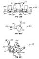
- FIGS. 7A-Care views of one embodiment of an adjacent level facet arthroplasty device
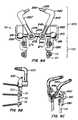
- FIGS. 8A-Care views of another embodiment of an adjacent level facet arthroplasty device;
- FIG. 8Dillustrates yet another embodiment;
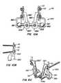
- FIG. 9Ais a dorsal view of the embodiment of FIG. 7A connected to a spinal fusion device;
- FIG. 9Bis a side view of the device of FIG. 9B ;
- FIG. 9Cis a perspective view of the device;
- FIG. 10Ais a dorsal view of the embodiment of FIG. 8A connected to a spinal fusion device;
- FIG. 10Bis a side view of the device of FIG. 8B ;
- FIG. 10Cis a perspective view of the device;
- FIG. 11Ais a dorsal view of another embodiment of a facet replacement system where the devices are implanted in combination with a spinal fixation system;
- FIG. 11Bis a side view of the device installed;
- FIG. 11Cis a perspective view of the device installed;
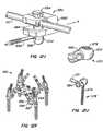
- FIGS. 12A-Udepict various connection and attachment systems suitable for use with the invention
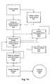
- FIG. 13is a flow chart of a method according to the invention.
- FIG. 14is a flow chart of another method according to the invention.
- the inventionrelates to implantable devices, including prosthesis suitable for implantation within the body to restore and/or augment connective tissue such as bone, and systems for treating spinal pathologies.
- the inventionrelates generally to implantable devices, apparatus or mechanisms that are suitable for implantation within a human body to restore, augment, and/or replace soft tissue and connective tissue, including bone and cartilage, and systems for treating spinal pathologies.
- the implantable devicescan include devices designed to replace missing, removed or resected body parts or structure.
- the implantable devices, apparatus or mechanismsare configured such that the devices can be formed from parts, elements or components which alone, or in combination, comprise the device.
- the implantable devicescan also be configured such that one or more elements or components are formed integrally to achieve a desired physiological, operational or functional result such that the components complete the device.
- Functional resultscan include the surgical restoration and functional power of a joint, controlling, limiting or altering the functional power of a joint, and/or eliminating the functional power of a joint by preventing joint motion.
- Portions of the devicecan be configured to replace or augment existing anatomy and/or implanted devices, and/or be used in combination with resection or removal of existing anatomical structure.
- the devices of the inventionare designed to interact with the human spinal column 10 , as shown in FIG. 1 , which is comprised of a series of thirty-three stacked vertebrae 12 divided into five regions.
- the cervical regionincludes seven vertebrae, known as C 1 -C 7 .
- the thoracic regionincludes twelve vertebrae, known as T 1 -T 12 .
- the lumbar regioncontains five vertebrae, known as L 1 -L 5 .
- the sacral regionis comprised of five fused vertebrae, known as S 1 -S 5
- the coccygeal regioncontains four fused vertebrae, known as Co 1 -Co 4 .
- FIG. 2depicts a superior plan view of a normal human lumbar vertebra 12 .
- human lumbar vertebraevary somewhat according to location, the vertebrae share many common features.
- Each vertebra 12includes a vertebral body 14 .
- Two short boney protrusions, the pedicles 16 , 16 ′,extend dorsally from each side of the vertebral body 14 to form a vertebral arch 18 which defines the vertebral foramen.
- each pedicle 16At the posterior end of each pedicle 16 , the vertebral arch 18 flares out into broad plates of bone known as the laminae 20 .
- the laminae 20fuse with each other to form a spinous process 22 .
- the spinous process 22provides for muscle and ligamentous attachment.
- a smooth transition from the pedicles 16 to the laminae 20is interrupted by the formation of a series of processes.
- Two transverse processes 24 , 24 ′thrust out laterally, one on each side, from the junction of the pedicle 16 with the lamina 20 .
- the transverse processes 24 , 24 ′serve as levers for the attachment of muscles to the vertebrae 12 .
- the superior articular processes 26 , 26 ′are sharp oval plates of bone rising upward on each side of the vertebrae, while the inferior processes 28 , 28 ′ are oval plates of bone that jut downward on each side. See also FIG. 4 .
- the superior and inferior articular processes 26 and 28each have a natural bony structure known as a facet.
- the superior articular facet 30faces medially upward, while the inferior articular facet 31 (see FIG. 3 ) faces laterally downward.
- the facets 30 and 31capped with a smooth articular cartilage and encapsulated by ligaments, interlock to form a facet joint 32 .
- the facet jointsare apophyseal joints that have a loose capsule and a synovial lining.
- the facet joint 32is composed of a superior facet and an inferior facet.
- the superior facetis formed by the vertebral level below the joint 32
- the inferior facetis formed in the vertebral level above the joint 32 .
- the superior facet of the joint 32is formed by bony structure on the L 5 vertebra (i.e., a superior articular surface and supporting bone 26 on the L 5 vertebra)
- the inferior facet of the joint 32is formed by bony structure on the L 4 vertebra (i.e., an inferior articular surface and supporting bone 28 on the L 4 vertebra).
- the angle formed by a facet joint located between a superior facet and an inferior facetchanges with respect to the midline depending upon the location of the vertebral body along the spine.
- the facet jointsdo not, in and of themselves, substantially support axial loads unless the spine is in an extension posture (lordosis).
- the orientation of the facet joint for a particular pair of vertebral bodieschanges significantly from the thoracic to the lumbar spine to accommodate a joint's ability to resist flexion-extension, lateral bending, and rotation.
- FIG. 4illustrates a posterolateral oblique view of a vertebrae 12 , further illustrating the curved surface of the superior articular facet 30 and the protruding structure of the inferior facet 31 adapted to mate with the opposing superior articular facet.
- the position of the inferior facet 31 and superior facet 30varies on a particular vertebral body to achieve the desired biomechanical behavior of a region of the spine.
- the overall spinecomprises a series of functional spinal units that are a motion segment consisting of two adjacent vertebral bodies, the intervertebral disc, associated ligaments, and facet joints.
- functional spinal unitsthat are a motion segment consisting of two adjacent vertebral bodies, the intervertebral disc, associated ligaments, and facet joints.
- a natural facet jointsuch as facet joint 32 ( FIG. 3 ) has a superior facet 30 and an inferior facet 31 .
- the superior facet of the jointis formed by the vertebral level below the joint, which can thus be called the “caudal” portion of the facet joint because it is anatomically closer to the tail bone or feet of the person.
- the inferior facet of the facet jointis formed by the vertebral level above the joint, which can be called the “cephalad” portion of the facet joint because it is anatomically closer to the head of the person.
- a device that, in use, replaces the caudal portion of a natural facet jointi.e., the superior facet 30
- a device that, in use, replaces the cephalad portion of a natural facet jointi.e., the inferior facet 31
- a cephalad devicea device that, in use, replaces the cephalad portion of a natural facet joint.
- embodiments of the spinal devices of the present inventioninclude modular designs that are either or both configurable and adaptable.
- the various embodiments disclosed hereinmay also be formed into a “kit” or system of modular components that can be assembled in situ to create a patient specific solution.
- kitor system of modular components that can be assembled in situ to create a patient specific solution.
- imaging technologyimproves, and mechanisms for interpreting the images (e.g., software tools) improve, patient specific designs employing these concepts may be configured or manufactured prior to the surgery.
- patient specific deviceswith integrally formed components that are pre-configured.
- a configurable modular device designallows for individual components to be selected from a range of different sizes and utilized within a modular device.
- sizeis to provide caudal and cephalad stems of various lengths.
- a modular implantable device designallows for individual components to be selected for different functional characteristics as well.
- One example of functionis to provide stems having different surface features and/or textures to provide anti-rotation capability.
- Other examples of the configurability of modular implantable device of the present inventionas described in greater detail below.
- Implantable devices of the present inventionare configurable such that the resulting implantable spinal device is selected and positioned to conform to a specific anatomy or desired surgical outcome.
- the adaptable aspect of embodiments of the present inventionprovide the surgeon with customization options during the implantation or revision procedure. It is the adaptability of the present device systems that also provides adjustment of the components during the implantation procedure to ensure optimal conformity to the desired anatomical orientation or surgical outcome.
- An adaptable modular device of the present inventionallows for the adjustment of various component-to-component relationships.
- One example of a component-to-component relationshipis the rotational angular relationship between a crossbar mount and the crossbar.
- Other examples of the adaptability of modular device of the present inventionas described in greater detail below.
- Configurabilitymay be thought of as the selection of a particular size of component that together with other component size selections results in a “custom fit” implantable device. Adaptability then can refer to the implantation and adjustment of the individual components within a range of positions in such a way as to fine tune the “custom fit” devices for an individual patient.
- the net resultis that embodiments of the modular, configurable, adaptable spinal device and systems of the present invention allow the surgeon to alter the size, orientation, and relationship between the various components of the device to fit the particular needs of a patient during the actual surgical procedure.
- anatomical references of the body 50with respect to which the position and operation of the devices, and components thereof, are described.
- Devices positioned within the bodycan be positioned dorsally 70 (or posteriorly) such that the placement or operation of the device is toward the back or rear of the body.
- devicescan be positioned ventrally 72 (or anteriorly) such that the placement or operation of the device is toward the front of the body.
- Various embodiments of the spinal devices and systems of the present inventionmay be configurable and variable with respect to a single anatomical plane or with respect to two or more anatomical planes.
- a componentmay be described as lying within and having adaptability or operability in relation to a single plane.
- a stemmay be positioned in a desired location relative to an axial plane and may be moveable between a number of adaptable positions or within a range of positions.
- the various componentscan incorporate differing sizes and/or shapes in order to accommodate differing patient sizes and/or anticipated loads.
- FIG. 6Ais a view of a portion of the spine 10 having a spinal fusion implant 100 (such as the spinal fusion rod and screw system commercially available from SeaSpine corporation) from a side view positioned in the sagittal plane.
- the spinal implant 100has a rod 110 which is anchored to the spine 10 with one or more anchors 120 , such as bone screws that penetrate the vertebral body 14 .
- the anchors 120are fixed to the rod 110 via attachment mechanisms 115 .
- FIG. 6Bis a dorsal view of a portion of the spine 10 having a spinal implant 100 .
- the spinal implanthas a pair of rods 110 , 110 ′ which are anchored to the spine 10 with one or more anchors 120 (shown in FIG. 9A ) fixed to the rods 110 , 110 ′ via attachment mechanisms 115 .
- spinal fixation systemscan also be employed without departing from the scope of the invention.
- systems using cables to stabilize the spine instead of rodscan be employed.
- the devicecan be used in combination with fixation systems positioned anteriorly, posteriorly, and laterally with respect to the spinal column.
- FIG. 7Ais a posterior view of an anchorable facet replacement device 200 according to one embodiment of the present invention.
- the device 200includes a crossbar 205 , a pair of cephalad arms 220 , 220 ′ and a pair of connectors 230 , 230 ′.
- the facets 30 and 31 of the vertebral bodyare replaced by the cooperative operation of the crossbar 205 , the cephalad arms 220 , 220 ′ and the adaptable crossbar mounts 276 that join the cephalad arms 220 , 220 ′ to the crossbar 205 , interacting with the caudal device 250 .
- the components of the cephalad implantable device 200are designed to provide appropriate configurability and adaptability for the given disease state, patient specific anatomy and spinal level where the implant occurs.
- the crossbar 205has a first end 210 and a second end 215 .
- the crossbar 205can be formed from a two piece bar where the first end 210 is attached to a threaded male portion having threads (not shown).
- the crossbar second end 215can be attached to a threaded female portion sized to receive the threads. It is contemplated that the threaded ends allow for the width of the crossbar to be adjusted to mate with the width between caudal bearings 250 .
- crossbar 205could include a series of solid crossbars of varying widths and/or thicknesses, or an adjustable crossbar having some form of locking or biasing mechanism (such as a spring-loaded tensioner or detent mechanism, etc.), as would be appreciated by those of skill in the art.
- end 210can be configured to have a threaded male portion (instead of female portion) that fits within a female threaded portion of the crossbar 205 without departing from the scope of the invention.
- a pair of cephalad arms 220are also illustrated in the exemplary embodiment of the anchorable, adaptable implantable device 200 of the present invention.
- Each cephalad arm 220 , 220 ′includes a bone engaging end 225 , 225 ′ and an end 240 , 240 ′ adapted to couple to the crossbar 205 .
- the caudal end 240 adapted to engage the crossbar 205includes an arm 245 and an elbow 247 .
- the caudal end 240is attached to the crossbar using the crossbar mount 276 .
- the bone engaging cephalad end 225includes a cephalad stem 230 and a distal tip 235 .
- the cephalad stem 230 and the distal tip 235are threaded or otherwise configured to engage the bone.
- the distal tip 235could be formed integrally with the cephalad stem 230 , of the same or a different material as the cephalad stem 230 .
- the surface of the cephalad stem 230can be a textured surface or any other modified surface such as, for example, a surface that assists or promotes bony in-growth.
- the crossbar mount 275is a connection structure to couple the cephalad prosthesis elements 220 to the crossbar 205 .
- the crossbar mount 275includes a cephalad arm engaging portion 272 , a crossbar engaging portion 274 and a fixation element 276 .
- Embodiments of the crossbar mount 275provide adaptability between the cephalad prosthesis elements 220 and the crossbar 205 and the loading characteristics of the crossbar ends 10 , 215 and the caudal prosthesis 250 .
- a pair of caudal bearing elements 250are also illustrated in the exemplary embodiment of the configurable and adaptable cephalad stabilization device 200 of the present invention.
- Each of the caudal bearing elements 250includes a caudal cup 251 .
- the caudal cup 251includes a surface 255 adapted to receive a crossbar end and a surface to engage the caudal stem head engaging surface.
- Caudal connectors 230 , 230 ′are provided to connect the implantable device 200 to the rods 110 , 100 ′ of the spinal implant 100 below the connection mechanism 115 .
- the clamping mechanism 230can attach to various portions of the spinal implant 100 , including the rods 110 , 110 ′ or the connection mechanism 115 .
- clamping mechanisms 230 , 230 ′can further be adapted to lock onto the spinal implant 100 by providing an additional connection mechanism 231 such as a bolt.
- FIG. 7Billustrates the implantable device 200 from a side view
- FIG. 7Cillustrates the device 200 from a perspective view.
- the devicecan be configured to function with only a single cephalad arm, thus allowing for a 3-point fixation mechanism, that in-turn is connected to the spinal fusion device.
- the cephalad arm 220can be coupled to the cross-bar 205 such that the length of the arm 220 from the bone engaging end 225 to the cross-bar engaging end 240 crosses the midline of the vertebra along the vertical length of the sagittal 54 plane.
- Other attachment mechanismscan be provided without departing form the scope of the invention.
- FIG. 8Ais a posterior view of an anchorable facet replacement device 300 according to an alternate embodiment of the present invention.
- the device 300includes a crossbar 305 , a pair of cephalad arms 320 , 320 ′ and a pair of cephalad connectors 330 , 330 ′.
- the facets 30 and 31 of the vertebral bodyare replaced by the cooperative operation of the crossbar 305 , the cephalad arms 320 , 320 ′ and the adaptable crossbar mounts 275 that join the cephalad arms 320 , 320 ′ to the crossbar 305 join the device to an implant, interacting with the caudal device 350 .
- the components of the caudal implantable device 300are designed to provide appropriate configurability and adaptability for the given disease state, patient specific anatomy and spinal level where the implant occurs.
- the crossbar 305has a first end 310 and a second end 315 .
- the crossbar 305can be formed from a two piece bar where the first end 310 is attached to a threaded male portion having threads (not shown).
- the crossbar second end 315can be attached to a threaded female portion sized to receive the threads. It is contemplated that the threaded ends allow for the width of the crossbar to be adjusted to mate with the width between caudal bearings 350 .
- crossbar 305could include a series of solid crossbars of varying widths and/or thicknesses, or an adjustable crossbar having some form of locking or biasing mechanism (such as a spring-loaded tensioner or detent mechanism, etc.), as would be appreciated by those of skill in the art.
- end 310can be configured to have a threaded male portion (instead of female portion) that fits within a female threaded portion of the crossbar 305 without departing from the scope of the invention.
- a pair of caudal bearing elements 350are also illustrated in the exemplary embodiment of the configurable and adaptable device 300 of the present invention.
- Each of the caudal bearing elements 350includes a caudal cup 351 and a fixation element 360 .
- the caudal cup 351includes a surface 355 adapted to receive a crossbar end and a surface to engage the caudal stem head engaging surface.
- the fixation element 360includes a caudal stem 365 and a distal tip 370 .
- the distal tip 370can be formed integrally with the caudal stem 365 , of the same or a different material as the caudal stem 365 .
- the caudal stem 365 and distal tip 370can be threaded or otherwise configured to engage.
- Cephalad connectors 330 , 330 ′are provided to connect the implantable device 300 to the rods 110 , 100 ′ of the spinal implant 100 below the connection mechanism 115 .
- the clamping mechanism 330can attach to various portions of the spinal implant 100 , including the rods 110 , 100 ′ or the connection mechanism 115 .
- Other devicescan be provided that are attached to all or part of the spinal implant 100 , including cross-connectors and/or lateral rod connectors (not shown), or combinations thereof.
- the clamping mechanisms 330 , 330 ′can further be adapted to lock onto the spinal implant 100 by providing an additional connection mechanism 331 such as a bolt or a screw.
- FIG. 8Billustrates the implantable device 300 from a side view
- FIG. 8Cillustrates the device 300 from a perspective view.
- the devicecan be configured to provide a single caudal arm, thus providing a 3-point fixation mechanism that, in turn, is connected to the spinal fusion device.
- the caudal arm 320can be coupled to the cross-bar 305 such that the length of the arm 320 from the spinal fusion engaging end to the cross-bar engaging end 340 crosses the midline of the vertebra along the vertical length of the sagittal 54 plane.
- FIG. 8Dillustrates an implantable device 300 suitable for use in a fusion system wherein the fusion system is being converted mid-length to provide for motion at a target joint.
- the device 301has a cross-bar 305 which engages twp caudal cups 350 on either end.
- Caudal arms 320 , 320are provided to connect the device to a spinal fixation device (such as device 100 ).
- Cephalad connectors 230 , 230 ′are provided to connect the device to a second spinal fixation device.
- the implantable device 301provides an articulable device between two implanted devices that stabilize the spine both in the caudal and cephalad direction.
- Either of the caudal arms 320 , 320 ′ or the cephalad connectors 230 , 230 ′can be configured to engage the spinal fusion device 100 along the rod 110 , the anchors 120 or the attachment mechanisms 115 .
- Configurationscan include, providing an aperture to receive, for example, a screw which engages the fusion device 100 , or configuring the arm 320 , 320 ′ or connector 230 , 230 ′ to hook around the fusion device, e.g., around the rod.
- FIGS. 9A , 9 B and 9 Cillustrate a spinal fusion implant 100 and facet replacement device 200 (see FIG. 7A ) implanted on a portion of a spine 10 .
- the spinal fusion implant 100has been depicted at an angle relative to the facet replacement device 200 .
- the orientation of the spinal fusion implant 100 and the facet replacement device 200can be varied, as desired.
- the anchoring mechanism of the spinal fusion implant 100have not been depicted in each depiction to avoid obscuring the invention.
- the design of the device 200is such that it can be implanted during an open surgical procedure, or can be implanted through less-invasive and/or minimally-invasive means.
- the various components of the device 100can be delivered percutaneously. Moreover while various components described can be implanted into the pedicles, these components, and variations thereof, can be implanted or secured to the pedicles, the lamina, the vertebral body, or combinations thereof.
- FIGS. 10A , 10 B and 10 Cillustrate an alternative system 98 for achieving spine stabilization and facet function restoration.
- FIG. 11Aillustrates an implanted system 97 from the dorsal view.
- Two or more vertebraare stabilized with a spinal fusion implant 100 and the facet joint to the next adjacent cephalad vertebra is partially or completely replaced by a device 200 while the facet joint to the next adjacent caudal vertebra is partially or completely replaced by a device 300 .
- FIG. 11Billustrates the implanted system 97 from the side view;
- FIG. 11Cillustrates the system from a perspective view.
- the length of the spine stabilization system 100 employedcan vary depending upon the number of vertebra to be fused.
- the device of FIG. 8Dcan also be employed in a system, such as 97 , to provide a combination of fusion with articulation.
- FIG. 12illustrates various connection and attachment designs useful, in whole or in part, in embodiments of the invention.
- FIG. 12Aillustrates a connector 400 having a bearing 402 connected to an arm 404 .
- the connector 400has an arm holder 406 that connects the arm 404 to a sleeve 410 .
- the connector illustrated in FIG. 12Benables a spinal implant, such as those depicted above, to be anchored to the spine 10 by positioning a portion of the vertebral body within the hook 410 .
- the rod 110 (shown in FIGS. 7-8 ) of the spinal implantcan then be inserted laterally through the opening 412 defined between the lateral portion 414 of extension 416 and flange 418 of connector portion 420 .
- FIG. 12Cillustrates another internal fixation device suitable for use with this invention.
- the internal fixation device 430attaches to a fixation rod 110 , 110 ′ and comprises a hook 432 with a screw device 434 with an axis 436 .
- the hook 432has an actual hook element 438 and a shackle element 440 which grips a portion of the spine.
- the shackle element 440is used to fasten the fixation rod 110 and the hook 432 on each other.
- the shackle element 440forms a groove with a groove bottom 442 , against which the fixation rod 110 , 110 ′ rests, and two lateral walls 444 , 444 ′ following the groove bottom 442 .
- the two lateral walls 444 , 444 ′ of the shackle element 440are clamped together by means of the screw device having the axis 436 by means of which the fixation rod 110 , 110 ′ can be clamped in place with its area received in the shackle element 440 .
- FIG. 12Dillustrates a transverse connector 450 suitable for use with the present invention.
- the connector 450joins two elongated spinal stabilizers 452 , 452 ′, (but which could also comprise plates), fixed to a number of vertebrae by means of anchoring members which are not shown.
- the transverse connectorhas a linking assembly having a first 454 and a second part 456 which each have an end portion terminating in a clamp 458 , 458 ′.
- a variety of clamping structurescould be used. They can be the same or different. For example, the clamp on one side could be closed while the clamp on the opposing side could be open. However, preferably, the clamps each include a recess 458 , 458 ′ which receive a respective rod.
- Setscrews 461can be employed and received in threaded bores each terminating in a beveled area 462 , 462 ′ which biases the rod into a retaining contact with the recess.
- the longitudinal axis of the setscrewis offset from the longitudinal axis of the rod receiving recess so that the setscrew will bias the rod into the recess.
- the setscrewsmay include internal hexes, or other suitable torque driving means, for tightening.
- the recesses 458 , 460are both open toward a central medial line or toward each other. This arrangement can be used for initial placement of the connector on the rod 110 ( FIG. 6 ).
- the connector assemblycan be placed onto the rods and then tightened with respect to the length.
- the second member 456 of the transverse connectorincludes a bore 462 , which receives an extension portion 464 which extends outwardly from the clamp 458 of the first part 454 .
- the extensioncan move in and out of the bore 462 to contract or expand the length of the space connected and the extension 464 can rotate in the bore 462 to change the relative angle of the openings of the rod recesses of the clamps to accommodate a varying relative angle of the longitudinal axis of the rods 110 .
- the first and second members, 454 , 456can include a limit mechanism such as a flanged end on the extension 464 .
- this flanged endis inserted into a vertical keyway 466 which is a vertical slot in the first member having an enlarged opening that is slightly larger than the diameter of the annular flange, and which will accommodate entry of the larger diameter flanged end.
- An undercutcan be provided on either side of the keyway to allow for captured movement of the flanged end in the keyway, but allow for restriction against movement out of the keyway 466 .
- a vertical slotted areais slightly wider than the diameter of the extension.
- FIG. 12Eillustrates a bar 110 with a threaded screw connector 470 .
- a hollow connector 472is provided to engage the rod 110 .
- a fastener 474pivotally connects the bone anchoring bolt 476 , having threads 478 , such that the connector 470 can attach a bar or cable 110 to a bone.
- FIG. 12Fillustrates a perspective view of a mounting device 480 .
- the device 480comprises a connector 482 with two screws 484 , 484 ′ adapted to form a screw-nut link by engaging the duct 486 of the head 488 of the connector.
- the connectorhas two vertical plane faces 490 comprising a front face and a rear face, which faces are substantially parallel and extend continuously over the full height of the connector.
- the connectoralso has two horizontal plane faces comprising a top face and a bottom face 492 , 492 ′ that are parallel to each other and substantially perpendicular to the above-mentioned vertical faces 490 .
- the connectorhas a generally cylindrical duct 486 extending parallel to the front and rear faces 490 , halfway between them, and perpendicular to the top and bottom faces 492 , 492 ′ through which it opens out.
- the connectoris axially symmetrical about the axis of the duct 486 .
- the connectorhas two slots 494 , 494 ′ extending generally parallel to the top and bottom faces 492 , 492 ′ in two side faces 496 of the connector that extend perpendicularly to the front and rear faces 490 .
- Each slot 494 , 494 ′is generally of channel section being defined by a top face 498 parallel to the top face 492 of the connector, a web face parallel to the side faces 496 of the connector, and a bottom face 498 ′ facing the top face 498 and extending perpendicularly to the front and rear faces 490 while being slightly inclined towards the inside of the connector.
- the angle between the top and bottom faces 498 , 498 ′ of the slotcan lie in the range 2 to 10°, for example.
- the slots 494 , 494 ′co-operate with the duct 486 which extends between them to define a housing for receiving a cross-member 500 , as described below.
- the slots 494 , 494 ′define two junctions between which the duct 486 and the housing extend.
- a portion of the connector extending above the junctionsforms a head 502 .
- the two side faces 496 on the head 502are shaped like two sectors of a common cylinder that is coaxial with the duct 486 .
- the connectorhas a bottom cylindrical face 504 contiguous with the bottom face 498 of the connector, perpendicular to the duct 486 , and halfway between the two side faces 496 . Between them, the slots 494 , 494 ′ and the cylindrical face 504 define two jaws 506 , 506 ′ each connected to the head 502 by the two junctions.
- the connectorOn each junction, the connector has a notch 508 extending away from the jaws 506 , 506 ′ towards the head 502 .
- the diameter of the duct 486is smaller in the head 502 than in the remainder of the connector. Inside the head 502 , the duct 486 has a thread.
- the devicehas two screws 484 each adapted to form a screw-nut link by engaging in the duct 486 of the head 502 of a respective connector.
- Each screw 484has a hexagonal socket 510 for receiving a hexagonal key for turning the screw 484 received in the duct 486 .
- the devicehas two rectilinear longitudinal rods 512 , 512 ′ for extending along the backbone of a patient, each being fixed to the vertebrae by anchor members using techniques known in the art.
- the two rods 512 , 512 ′typically have a circular profile as illustrated with a diameter the same as the cylindrical face 504 between the jaws.
- the jaws 506 , 506 ′are adapted to make surface-on-surface contact with the rod.
- the cylindrical faces 504 of the jawstogether extend over a circular arc of total extent exceeding 180° and selected as a function of the properties of the material of the connector so as to enable the jaws 506 , 506 ′ to be engaged on the rod 512 , 512 ′ by being snap-fastened thereon.
- the cylindrical faces 504 of the jawspresent a geometrical outline which extends beyond the bottom face 492 ′ of the connector 482 .
- the rodprojects beyond the jaws in a radial direction.
- the devicehas a rectilinear cross-member 514 of generally rectangular section adapted to be received in the housings, passing right through the connectors 482 .
- FIG. 12Gillustrates another connection system 520 .
- a rod 110is received through aperture 522 in a pivotal head 524 attached to an anchoring dowel 526 for anchoring the device 520 to the bone.
- the positioning and locking device 530is made up of an upper jaw member 532 and a lower jaw member 534 having opened faces which are machined with assembly notches 536 to allow one to be positioned and pivoted against the other, leaving an opening 538 at the opposite end.
- a bushing, or hollow shaft, 540passes through the two jaws 532 , 534 at right angles and then through the opposite end of the jaws, with respect to the gripping jaw opening.
- Bushing 540at its upper part 542 , has the shape of a cone frustum with slots 544 which start from this upper part 542 and run in the direction of the axis of the bushing to end about halfway down the length thereof.
- bushing 540The lower part of bushing 540 is threaded at 546 and is screwed into a nut 548 which clamps the two jaws 532 , 534 together.
- a spring in the form of a staple 550 or bent wireis housed inside holes 552 each made in each one of the jaws 532 , 534 also on the opposite side to the opening of the gripping jaw.
- Upper jaw 532has a conical recess in its upper part and a cylindrical bore to accommodate bushing 540 and lower jaw 534 has a bore which has two opposed flat surfaces to play a part in holding bushing 540 in place especially against rotation, these flat surfaces not being depicted in the drawing.
- Bushing 540can have a smaller diameter in its threaded lower part 546 and in its central part has two opposed flat surfaces, not shown in the drawing, which engage the flats on lower jaw 534 to prevent bushing 540 from rotating relative to the jaws and allow the nut to be locked. Between bushing 540 and the bores of jaw 534 , 536 there is a clearance that allows the jaws device 530 to be pivoted outwardly against the face of staple spring 550 , prior to the tightening operation. The clearance allows the jaws 532 , 534 to be parted just enough for clipping an element between the faces of each jaw, for example, onto a rod or a hoop along which device 530 can slide and therefore change position.
- a rod 110may be inserted into bushing 540 and locked in position by the clamping action of the conical position of the upper part of bushing 540 which deforms inwardly as nut 548 is tightened pulling the bushing downwardly into the conical recess of upper jaw 532 .
- This rod 110may remain fixed in a concrete assembly position so that one can adjust the relative positions of all the elements of the device prior to the final operation of tightening the assembly.
- FIG. 12Iis a perspective view of the constructed clamp 550 with a small cut-away to show the junction between the pin connector 552 and the connecting rod 110 .
- Tightening the bolt 554draws the pin 556 against the distal outer surface 558 of the clamp body 560 . This action braces the pin against the clamp preventing the rotation of the pin connector 552 and thus the pin 556 .
- the pin 556is prevented from moving axially with respect to connector 552 .
- Tightening the bolt 554additionally draws the rod-engaging surface 580 of the connector 552 into engagement with the connecting rod 110 . This interference has a number of effects that further prohibit any movement of the tightened clamp 550 .
- friction between the rod-engaging surface 580 and the outer surface of the rod 110further prevents any rotation of the pin connector 552 .
- the force exerted by the pin connector at this junctionpushes the rod 110 in the direction of arrow b.
- Thisensures that the rod 110 is seated against the back wall 582 of the slot 584 providing a good rigid mechanical junction between the connecting rod 110 and the clamp body 560 preventing rotation of the clamp body around or sliding along the connecting rod 110 .
- the clamp body 560does not substantially squeeze-down on or close over the connecting rod when the bolt 554 is tightened. It is only the interference between the rod-engaging surface and the rod 110 that prevents movement between the rod 110 and clamp 550 .
- FIG. 12Jillustrates an attachment mechanism 570 has a threaded nut 572 having female threads 574 for engaging the shaft 576 of an anchoring shaft 578 .
- the threaded nut 572has a clamp 580 for engaging a rod 110 .
- the clamp 580forms an adjustable aperture 582 .
- the aperture 582is adjusted by tightening a fastener 584 .
- FIG. 12Killustrates a bone bolt 590 suitable for use with the invention.
- Bone bolt 590is shown attached to a clamp 592 with the longitudinal axis L 1
- clamp 592is shown attached to a spinal implant rod 594 with a longitudinal axis L 2 .
- Clamp 592includes a clamp bolt 596 , an arm 598 , a rod interface washer 600 , a set screw 602 , and a nut 604 .
- Clamp bolt 596has an aperture 606 for receiving rod 594 , and while the aperture is shown closed around rod 594 , it will nevertheless be understood that an open-sided aperture may also be used to permit top-loading of rod 594 into clamp 592 .
- Set screw 602is inserted through a threaded opening 608 and into aperture 606 in clamp bolt 596 so as to allow set screw 602 to push against rod 594 .
- Arm 598has a bore 610 for receiving bone bolt 590 .
- Arm 598is simultaneously tightened to clamp 592 when set screw 602 is tightened against rod 594 .
- rod 594pushes against rod interface washer 600 , which pinches arm 598 between rod interface washer 600 and stop 612 .
- set screw 602acts as a compression member to tighten clamp 592 and achieve substantial fixation of arm 598 to rod 594 .
- FIG. 12Ldepicts fasteners 620 suitable for use in the invention.
- the fastener 620has an aperture 622 for receiving a rod 110 (not shown) and is adopted to allow the diameter of the aperture 622 to increase and decrease in order to facilitate engaging the rod 110 .
- a bolt 624is provided to communicate through a second aperture 626 to decrease the aperture 622 that received the rod.
- FIG. 12M retainer assembly 630includes a set screw 632 and a generally rectangular retainer block 634 into which angular member 636 and rod 110 extend.
- Block 634has a rod passage 638 which receives rod 110 .
- Rod 110(not shown) can have a substantially circular cross-section; however, rods having various other cross-sections, such as hexagonal or oval cross-sections, could be used with corresponding modifications to rod passage 638 .
- Block 634also includes a transverse passage 640 which receives inner end portion 642 of angular member 636 and communicates with rod passage 638 .
- Transverse passage 640includes a plurality of mating surfaces 644 which engage similarly shaped retaining surfaces or teeth 646 that project radially outwardly from inner end portion 642 of angular member 636 . Meshing engagement between mating surfaces 644 on block 634 and teeth 648 on inner end portion 642 prevents rotational movement of angular member 636 about a longitudinal central axis 650 of inner end portion 642 . It is understood that mating surfaces of various shapes may be formed in transverse passage 640 to receive similarly shaped retaining surfaces formed on block 634 .
- FIG. 12Nillustrates another attachment mechanism 660 .
- Pincers 662attached to the vertebras, formed by two curved claws with opposite concavities, one of which 664 forms part of the body 666 of the pincer and the other 668 independent, with a cylindrical lateral prolongation 610 which on passing tightly through the body 666 of the pincer allows it to make axial or turning displacements to adapt the relative position of the two claws to the shape and sizes of the zone of the vertebra where it is fastened.
- FIG. 12Oillustrates yet another attachment mechanism 680 .
- a crossbar 682is provided with a clamping mechanism 684 having a sizable aperture 686 .
- the sizable aperture 686is adjustable by adjusting screw 688 .
- the aperture 686is configured to, for example, receive a rod 110 .
- FIG. 12Pillustrates an alternate mechanism 640 .
- a pair of parallel rods 642 , 642 ′are provided.
- the first parallel rod 642is integrated with a connector 644 for the second parallel rod 642 ′.
- the second parallel rod 642 ′can be fed through an aperture 646 on the connector 644 .
- a nut 648is provided to secure the second nut 642 ′ in the aperture 646 .
- FIG. 12Qillustrates a connector 770 having a rod 110 connected to a crossbar 772 .
- the rodis secured through an aperture 774 .
- a nut 776is provided to secure the rod 110 .
- FIG. 12Rillustrates a connector assembly 780 suitable for use with the invention from a perspective view, an end view and a top view.
- the assemblyattaches spinal implant rod 110 with a longitudinal axis L 1 to the shaft of a vertebral anchor with the longitudinal axis.
- Connection assembly 780includes a bolt 782 , a clevis 784 , a rod interface washer 786 , and a set screw 788 .
- Bolt 782has an aperture 790 for receiving a rod 110 in a spinal implant system. While a closed aperture is depicted, it will be appreciated than an open-sided aperture may also be used to permit top loading the of the connector rod.
- Set screw 786is inserted through a threaded opening 792 in bolt 786 and into aperture 790 to allow set screw 786 to push against rod A.
- Clevis 784is a u-shaped piece with a bore 794 for receiving a vertebral anchor or bolt B and is simultaneously tightened when set screw 788 is tightened against rod A.
- the shaft Bmay be roughened and the interior of clevis 784 may be correspondingly roughened to increase friction between the pieces.
- rod Apushes against rod interface washer 786 . This force pinches the ends 796 and 798 of clevis 784 together between rod interface washer 786 and stop 800 , which tightens clevis 784 together between rod interface washer 786 and stop 790 .
- FIG. 12Sdepicts a multiaxial connector 700 suitable for the invention.
- the connector 700has a first connecting element 702 perforated with a bore 704 designed to receive the second threaded part 706 of the fixing screw 708 , another bore 710 comprising in its inner part an annular track 712 with spherical profile and a slot 714 passing through the bore 704 to emerge inside the bore 710 at the annular track 716 , a second connecting element 718 perforated with a bore 720 designed to receive the lining rod 722 of a threaded hole 724 co-operating with a clamping screw 726 for locking the rod in translation and linking means 728 forming a ball joint enabling the first and second elements to be coupled together such that the elements can pivot relative to each other to present the linking rod 729 in specific angular positions and to laterally offset the linking rod relative to the pivoting centre of the elements.
- FIG. 12Tillustrates a connection assembly 730 having a longitudinal member 732 and a housing 734 .
- Longitudinal member 732has an aperture 736 for receiving a rod 110 , for example in a spinal system. Open sided apertures can be used to permit top loading of the rod.
- a threaded opening 738is provided to communicate with a set screw 740 .
- the housing 734has a passageway 742 for receiving a shaft or shank of a vertebral anchor.
- FIG. 12Uillustrates a connection assembly 750 used with an offset connector or spindle.
- the assembly 750has aperture threaded bolt 752 for connection to bone.
- the fence bolt 752fits within an aperture 754 of an anchor 756 .
- a cross member 758connects the anchor 756 to a rod holder 760 .
- a rod 110fits within an aperture 762 of the rod holder.
- a set screw 764is provided to fix the location of the rod in the aperture.
- a second set screw 766is provided to fix the location of the fence bolt 752 within the aperture 754 of anchor 756 .
- connectorsthat would be suitable for use in the invention include, for example, those described in U.S. Pat. Nos. 6,231,575, 6,309,391, 6,340,361, 6,342,054, 6,368,320, 6,749,361; U.S. Patent Publication Nos. 2002/0049446, 2002/0042613, 2002/0013585, 2002/0013588, 2002/0082601; European Patent Nos. 1205152, 1103226; PCT Patent Publication Nos. WO 01/30248, WO 02/34150, WO 01/67972, WO 02/02024, WO 01/06939, WO 02/24149.
- an incisionis created 800 to access a target location of the spine.
- this devices of this applicationcan be implanted concurrently with the implantation of a spinal fusion device, such as a rod and screw, or in a subsequent procedure. If the devices are implanted concurrently with the fusion device, then the physician would proceed with first implanting the spinal fusion device 801 . Alternatively, where the fusion device has already been implanted (e.g., where this procedure revises the prior surgical procedure), then the physician accesses the implanted fusion device 802 immediately following creating the incision 800 .
- the physiciancan select one or more adjacent level arthroplasty devices 804 to use with the implanted spinal fusion device. Once the devices are selected 804 , the devices are then implanted 806 . As will be appreciated by those of skill in the art, due to the modularity of the designs employed, it is possible for the physician to choose a first adjacent level arthroplasty device, implant it in conjunction with the spinal fusion device and then select a different device based on, for example, experience or in situ appearance of the suitability of the device. Additionally, adjustments to the connection of the adjacent level arthroplasty device can be made without departing from the scope of the invention. Once the physician is satisfied with the selection, the incision is then closed 808 .
- FIG. 14depicts the flow chart for an alternate embodiment of a method of the present invention, particularly well suited for revision of an already-fused functional spinal unit, to partial or full natural motion.
- an incisionis created 900 to access a target location of the spine.
- the spinal fusion devicecan be implanted 901 at that time or during a previous procedure. As discussed, this procedure is well suited for a subsequent procedure.
- the physicianthen exposes at least a portion of the spinal fusion instrumentation 902 . Thereafter, the physician can remove and/or modify the components of the existing spinal fusion instrumentation. Removal and/or modification includes the resecting of individual fusion components, such as rods.
- the physiciancan access the intervertebral disk space 903 to separate any arthrodesis across the disk space as well as remove any fusion cages and/or other associated intervertebral fusion devices (including intervertebral spacer and/or dynamic stabilization devices) 904 .
- the physiciancan implant an artificial disk or nucleus replacement 905 .
- the physiciancan select one or more adjacent level arthroplasty devices 906 to use with the remaining components of the spinal fusion instrumentation. Once the devices are selected 906 , the devices are then implanted 907 .
- the physiciancan choose a first adjacent level arthroplasty device, implant it in conjunction with the spinal fusion device and then select a different device based on, for example, experience or in situ appearance of the suitability of the device. Additionally, adjustments to the connection of the adjacent level arthroplasty device can be made without departing from the scope of the invention. Once the physician is satisfied with the selection, the incision is then closed 908 . It should also be appreciated that the present method could be used to revise the fusion of a single functional spinal unit, or could be used in any portion or location of a spinal fusion spanning multiple spinal levels.
Landscapes
- Health & Medical Sciences (AREA)
- Orthopedic Medicine & Surgery (AREA)
- Life Sciences & Earth Sciences (AREA)
- Neurology (AREA)
- Surgery (AREA)
- Engineering & Computer Science (AREA)
- Biomedical Technology (AREA)
- General Health & Medical Sciences (AREA)
- Veterinary Medicine (AREA)
- Heart & Thoracic Surgery (AREA)
- Public Health (AREA)
- Animal Behavior & Ethology (AREA)
- Nuclear Medicine, Radiotherapy & Molecular Imaging (AREA)
- Medical Informatics (AREA)
- Molecular Biology (AREA)
- Vascular Medicine (AREA)
- Transplantation (AREA)
- Oral & Maxillofacial Surgery (AREA)
- Cardiology (AREA)
- Prostheses (AREA)
- Surgical Instruments (AREA)
Abstract
Description
Claims (20)
Priority Applications (3)
| Application Number | Priority Date | Filing Date | Title |
|---|---|---|---|
| US11/206,662US8398681B2 (en) | 2004-08-18 | 2005-08-17 | Adjacent level facet arthroplasty devices, spine stabilization systems, and methods |
| US13/771,881US9320547B2 (en) | 2004-08-18 | 2013-02-20 | Adjacent level facet arthroplasty devices, spine stabilization systems, and methods |
| US15/071,328US10098671B2 (en) | 2004-08-18 | 2016-03-16 | Adjacent level facet arthoroplasty devices, spine stabilization systems, and methods |
Applications Claiming Priority (3)
| Application Number | Priority Date | Filing Date | Title |
|---|---|---|---|
| US60282604P | 2004-08-18 | 2004-08-18 | |
| US69194605P | 2005-06-17 | 2005-06-17 | |
| US11/206,662US8398681B2 (en) | 2004-08-18 | 2005-08-17 | Adjacent level facet arthroplasty devices, spine stabilization systems, and methods |
Related Child Applications (1)
| Application Number | Title | Priority Date | Filing Date |
|---|---|---|---|
| US13/771,881ContinuationUS9320547B2 (en) | 2004-08-18 | 2013-02-20 | Adjacent level facet arthroplasty devices, spine stabilization systems, and methods |
Publications (2)
| Publication Number | Publication Date |
|---|---|
| US20060052785A1 US20060052785A1 (en) | 2006-03-09 |
| US8398681B2true US8398681B2 (en) | 2013-03-19 |
Family
ID=35262143
Family Applications (3)
| Application Number | Title | Priority Date | Filing Date |
|---|---|---|---|
| US11/206,662Active2028-06-07US8398681B2 (en) | 2004-08-18 | 2005-08-17 | Adjacent level facet arthroplasty devices, spine stabilization systems, and methods |
| US13/771,881Expired - LifetimeUS9320547B2 (en) | 2004-08-18 | 2013-02-20 | Adjacent level facet arthroplasty devices, spine stabilization systems, and methods |
| US15/071,328Expired - LifetimeUS10098671B2 (en) | 2004-08-18 | 2016-03-16 | Adjacent level facet arthoroplasty devices, spine stabilization systems, and methods |
Family Applications After (2)
| Application Number | Title | Priority Date | Filing Date |
|---|---|---|---|
| US13/771,881Expired - LifetimeUS9320547B2 (en) | 2004-08-18 | 2013-02-20 | Adjacent level facet arthroplasty devices, spine stabilization systems, and methods |
| US15/071,328Expired - LifetimeUS10098671B2 (en) | 2004-08-18 | 2016-03-16 | Adjacent level facet arthoroplasty devices, spine stabilization systems, and methods |
Country Status (7)
| Country | Link |
|---|---|
| US (3) | US8398681B2 (en) |
| EP (1) | EP1793753B1 (en) |
| JP (1) | JP2008510518A (en) |
| KR (1) | KR20070065329A (en) |
| AU (1) | AU2005277363A1 (en) |
| CA (1) | CA2576636A1 (en) |
| WO (1) | WO2006023671A1 (en) |
Cited By (15)
| Publication number | Priority date | Publication date | Assignee | Title |
|---|---|---|---|---|
| US20140066992A1 (en)* | 2004-08-18 | 2014-03-06 | Teena M. Augostino | Adjacent Level Facet Arthroplasty Devices, Spine Stabilization Systems, and Methods |
| US20140100610A1 (en)* | 2007-01-10 | 2014-04-10 | Gmedelaware 2 Llc | System and Method for Facet Joint Replacement |
| US8758411B1 (en) | 2011-10-25 | 2014-06-24 | Nuvasive, Inc. | Implants and methods for treating spinal disorders |
| US9763703B2 (en) | 2015-05-05 | 2017-09-19 | Degen Medical, Inc. | Cross connectors, kits, and methods |
| US10045824B2 (en) | 2013-10-18 | 2018-08-14 | Medicrea International | Methods, systems, and devices for designing and manufacturing a rod to support a vertebral column of a patient |
| US10292770B2 (en) | 2017-04-21 | 2019-05-21 | Medicrea International | Systems, methods, and devices for developing patient-specific spinal treatments, operations, and procedures |
| US10318655B2 (en) | 2013-09-18 | 2019-06-11 | Medicrea International | Method making it possible to produce the ideal curvature of a rod of vertebral osteosynthesis material designed to support a patient's vertebral column |
| US10456211B2 (en) | 2015-11-04 | 2019-10-29 | Medicrea International | Methods and apparatus for spinal reconstructive surgery and measuring spinal length and intervertebral spacing, tension and rotation |
| US10918422B2 (en) | 2017-12-01 | 2021-02-16 | Medicrea International | Method and apparatus for inhibiting proximal junctional failure |
| US11612436B2 (en) | 2016-12-12 | 2023-03-28 | Medicrea International | Systems, methods, and devices for developing patient-specific medical treatments, operations, and procedures |
| US11769251B2 (en) | 2019-12-26 | 2023-09-26 | Medicrea International | Systems and methods for medical image analysis |
| US11877801B2 (en) | 2019-04-02 | 2024-01-23 | Medicrea International | Systems, methods, and devices for developing patient-specific spinal implants, treatments, operations, and/or procedures |
| US11925417B2 (en) | 2019-04-02 | 2024-03-12 | Medicrea International | Systems, methods, and devices for developing patient-specific spinal implants, treatments, operations, and/or procedures |
| US12274511B2 (en) | 2019-04-02 | 2025-04-15 | Medicrea International | Systems and methods for medical image analysis |
| US12318144B2 (en) | 2021-06-23 | 2025-06-03 | Medicrea International SA | Systems and methods for planning a patient-specific spinal correction |
Families Citing this family (93)
| Publication number | Priority date | Publication date | Assignee | Title |
|---|---|---|---|---|
| US6974478B2 (en)* | 1999-10-22 | 2005-12-13 | Archus Orthopedics, Inc. | Prostheses, systems and methods for replacement of natural facet joints with artificial facet joint surfaces |
| US8187303B2 (en)* | 2004-04-22 | 2012-05-29 | Gmedelaware 2 Llc | Anti-rotation fixation element for spinal prostheses |
| US7674293B2 (en)* | 2004-04-22 | 2010-03-09 | Facet Solutions, Inc. | Crossbar spinal prosthesis having a modular design and related implantation methods |
| ATE285207T1 (en)* | 1999-10-22 | 2005-01-15 | Archus Orthopedics Inc | FACET ARTHROPLASTY DEVICES |
| US7691145B2 (en)* | 1999-10-22 | 2010-04-06 | Facet Solutions, Inc. | Prostheses, systems and methods for replacement of natural facet joints with artificial facet joint surfaces |
| US6811567B2 (en)* | 1999-10-22 | 2004-11-02 | Archus Orthopedics Inc. | Facet arthroplasty devices and methods |
| US20080177310A1 (en)* | 2000-10-20 | 2008-07-24 | Archus Orthopedics, Inc. | Facet arthroplasty devices and methods |
| US20040230304A1 (en)* | 2003-05-14 | 2004-11-18 | Archus Orthopedics Inc. | Prostheses, tools and methods for replacement of natural facet joints with artifical facet joint surfaces |
| US7608104B2 (en)* | 2003-05-14 | 2009-10-27 | Archus Orthopedics, Inc. | Prostheses, tools and methods for replacement of natural facet joints with artifical facet joint surfaces |
| US20040230201A1 (en)* | 2003-05-14 | 2004-11-18 | Archus Orthopedics Inc. | Prostheses, tools and methods for replacement of natural facet joints with artifical facet joint surfaces |
| US7074238B2 (en)* | 2003-07-08 | 2006-07-11 | Archus Orthopedics, Inc. | Prostheses, tools and methods for replacement of natural facet joints with artificial facet joint surfaces |
| US7588590B2 (en) | 2003-12-10 | 2009-09-15 | Facet Solutions, Inc | Spinal facet implant with spherical implant apposition surface and bone bed and methods of use |
| US20050131406A1 (en)* | 2003-12-15 | 2005-06-16 | Archus Orthopedics, Inc. | Polyaxial adjustment of facet joint prostheses |
| US9451990B2 (en)* | 2004-02-17 | 2016-09-27 | Globus Medical, Inc. | Facet joint replacement instruments and methods |
| US8562649B2 (en) | 2004-02-17 | 2013-10-22 | Gmedelaware 2 Llc | System and method for multiple level facet joint arthroplasty and fusion |
| WO2006055186A2 (en) | 2004-10-25 | 2006-05-26 | Archus Orthopedics, Inc. | Spinal prosthesis having a modular design |
| US7914556B2 (en)* | 2005-03-02 | 2011-03-29 | Gmedelaware 2 Llc | Arthroplasty revision system and method |
| US7051451B2 (en)* | 2004-04-22 | 2006-05-30 | Archus Orthopedics, Inc. | Facet joint prosthesis measurement and implant tools |
| US7406775B2 (en)* | 2004-04-22 | 2008-08-05 | Archus Orthopedics, Inc. | Implantable orthopedic device component selection instrument and methods |
| US20080082171A1 (en)* | 2004-04-22 | 2008-04-03 | Kuiper Mark K | Crossbar spinal prosthesis having a modular design and systems for treating spinal pathologies |
| US20070093833A1 (en)* | 2004-05-03 | 2007-04-26 | Kuiper Mark K | Crossbar spinal prosthesis having a modular design and related implantation methods |
| US7507242B2 (en) | 2004-06-02 | 2009-03-24 | Facet Solutions | Surgical measurement and resection framework |
| US7799081B2 (en)* | 2004-09-14 | 2010-09-21 | Aeolin, Llc | System and method for spinal fusion |
| WO2006034436A2 (en) | 2004-09-21 | 2006-03-30 | Stout Medical Group, L.P. | Expandable support device and method of use |
| US8092496B2 (en)* | 2004-09-30 | 2012-01-10 | Depuy Spine, Inc. | Methods and devices for posterior stabilization |
| US7896906B2 (en)* | 2004-12-30 | 2011-03-01 | Depuy Spine, Inc. | Artificial facet joint |
| US7766940B2 (en) | 2004-12-30 | 2010-08-03 | Depuy Spine, Inc. | Posterior stabilization system |
| US20060084976A1 (en) | 2004-09-30 | 2006-04-20 | Depuy Spine, Inc. | Posterior stabilization systems and methods |
| US20060079895A1 (en)* | 2004-09-30 | 2006-04-13 | Mcleer Thomas J | Methods and devices for improved bonding of devices to bone |
| US20060085075A1 (en)* | 2004-10-04 | 2006-04-20 | Archus Orthopedics, Inc. | Polymeric joint complex and methods of use |
| US8162985B2 (en)* | 2004-10-20 | 2012-04-24 | The Board Of Trustees Of The Leland Stanford Junior University | Systems and methods for posterior dynamic stabilization of the spine |
| US8025680B2 (en)* | 2004-10-20 | 2011-09-27 | Exactech, Inc. | Systems and methods for posterior dynamic stabilization of the spine |
| US8267969B2 (en) | 2004-10-20 | 2012-09-18 | Exactech, Inc. | Screw systems and methods for use in stabilization of bone structures |
| US7935134B2 (en)* | 2004-10-20 | 2011-05-03 | Exactech, Inc. | Systems and methods for stabilization of bone structures |
| US8226690B2 (en)* | 2005-07-22 | 2012-07-24 | The Board Of Trustees Of The Leland Stanford Junior University | Systems and methods for stabilization of bone structures |
| US20070239159A1 (en)* | 2005-07-22 | 2007-10-11 | Vertiflex, Inc. | Systems and methods for stabilization of bone structures |
| US7491238B2 (en)* | 2004-12-23 | 2009-02-17 | Impliant Ltd. | Adjustable spinal prosthesis |
| US8496686B2 (en)* | 2005-03-22 | 2013-07-30 | Gmedelaware 2 Llc | Minimally invasive spine restoration systems, devices, methods and kits |
| WO2006102443A2 (en)* | 2005-03-22 | 2006-09-28 | Archus Orthopedics, Inc. | Minimally invasive spine restoration systems, devices, methods and kits |
| US7695499B2 (en)* | 2005-04-29 | 2010-04-13 | Warsaw Orthopedic, Inc. | System, devices and method for augmenting existing fusion constructs |
| JP4613867B2 (en)* | 2005-05-26 | 2011-01-19 | ソニー株式会社 | Content processing apparatus, content processing method, and computer program |
| EP1903949A2 (en) | 2005-07-14 | 2008-04-02 | Stout Medical Group, L.P. | Expandable support device and method of use |
| US8523865B2 (en) | 2005-07-22 | 2013-09-03 | Exactech, Inc. | Tissue splitter |
| USH2261H1 (en) | 2005-09-26 | 2011-08-02 | Simmons Jr James W | Disc and facet replacement |
| US7695514B2 (en)* | 2005-12-29 | 2010-04-13 | Depuy Spine, Inc. | Facet joint and spinal ligament replacement |
| EP1973484B1 (en)* | 2006-01-09 | 2022-03-09 | Globus Medical, Inc. | System for multiple level facet joint arthroplasty and fusion |
| US20070233256A1 (en)* | 2006-03-15 | 2007-10-04 | Ohrt John A | Facet and disc arthroplasty system and method |
| EP2012686B1 (en)* | 2006-04-18 | 2013-10-02 | Joseph Nicholas Logan | Spinal rod system |
| EP2023864B1 (en) | 2006-05-01 | 2019-07-10 | Stout Medical Group, L.P. | Expandable support device |
| US7967847B2 (en)* | 2006-07-24 | 2011-06-28 | Warsaw Orthopedic, Inc. | Spinal stabilization and reconstruction with fusion rods |
| US8702755B2 (en)* | 2006-08-11 | 2014-04-22 | Gmedelaware 2 Llc | Angled washer polyaxial connection for dynamic spine prosthesis |
| US8096996B2 (en) | 2007-03-20 | 2012-01-17 | Exactech, Inc. | Rod reducer |
| US20080133016A1 (en)* | 2006-11-30 | 2008-06-05 | Warsaw Orthopedic, Inc. | Spinal arthroplasty device compatible with neural integrity monitoring |
| CA2675037A1 (en)* | 2007-01-10 | 2008-07-17 | Facet Solutions, Inc. | Taper-locking fixation system |
| US8133261B2 (en) | 2007-02-26 | 2012-03-13 | Depuy Spine, Inc. | Intra-facet fixation device and method of use |
| US8197513B2 (en) | 2007-04-13 | 2012-06-12 | Depuy Spine, Inc. | Facet fixation and fusion wedge and method of use |
| US8043334B2 (en)* | 2007-04-13 | 2011-10-25 | Depuy Spine, Inc. | Articulating facet fusion screw |
| US8894685B2 (en) | 2007-04-13 | 2014-11-25 | DePuy Synthes Products, LLC | Facet fixation and fusion screw and washer assembly and method of use |
| WO2009006622A2 (en)* | 2007-07-03 | 2009-01-08 | Innovative Spinal Technologies, Inc. | Facet fusion implant |
| CA2717610A1 (en)* | 2008-03-06 | 2009-09-11 | Synthes Usa, Llc | Facet interference screw |
| US20100049252A1 (en)* | 2008-08-21 | 2010-02-25 | Southern Spine, Llc | Transverse Connector Device for Extending an Existing Spinal Fixation System |
| US20100211176A1 (en) | 2008-11-12 | 2010-08-19 | Stout Medical Group, L.P. | Fixation device and method |
| WO2010056895A1 (en) | 2008-11-12 | 2010-05-20 | Stout Medical Group, L.P. | Fixation device and method |
| WO2010065277A1 (en) | 2008-11-25 | 2010-06-10 | Synthes Usa, Llc | Visco-elastic facet joint implant |
| US20100198262A1 (en)* | 2009-01-30 | 2010-08-05 | Mckinley Laurence M | Axial offset bone fastener system |
| WO2011006155A1 (en)* | 2009-07-10 | 2011-01-13 | K2M, Inc. | Transverse connector |
| EP2294994B1 (en)* | 2009-09-11 | 2018-04-04 | Stryker European Holdings I, LLC | External fixation component |
| USD632791S1 (en)* | 2009-09-11 | 2011-02-15 | Stryker Trauma Ag | Connector |
| EP2294995B1 (en)* | 2009-09-11 | 2018-04-04 | Stryker European Holdings I, LLC | Easy to clean clamping device |
| US20110218574A1 (en)* | 2010-03-03 | 2011-09-08 | Warsaw Orthopedic, Inc. | Dynamic vertebral construct |
| EP2555696B1 (en)* | 2010-04-08 | 2017-07-26 | Globus Medical, Inc. | Jointed rod |
| US8986355B2 (en) | 2010-07-09 | 2015-03-24 | DePuy Synthes Products, LLC | Facet fusion implant |
| US8920471B2 (en) | 2010-07-12 | 2014-12-30 | K2M, Inc. | Transverse connector |
| US9089372B2 (en) | 2010-07-12 | 2015-07-28 | DePuy Synthes Products, Inc. | Pedicular facet fusion screw with plate |
| ES2541831T3 (en) | 2010-10-07 | 2015-07-27 | Stryker Trauma Sa | Coupling element for an external fixing device |
| US9149286B1 (en) | 2010-11-12 | 2015-10-06 | Flexmedex, LLC | Guidance tool and method for use |
| USD704840S1 (en) | 2010-12-14 | 2014-05-13 | Stryker Trauma Sa | Hinge coupling |
| EP2465455B1 (en) | 2010-12-14 | 2015-04-08 | Stryker Trauma SA | Fixation clamp |
| USD683461S1 (en) | 2010-12-14 | 2013-05-28 | Stryker Trauma Sa | Hinge coupling |
| USD720853S1 (en) | 2010-12-14 | 2015-01-06 | Stryker Trauma Sa | Fixation clamp |
| EP2465454B1 (en) | 2010-12-14 | 2015-04-08 | Stryker Trauma SA | Fixation clamp with thumbwheel |
| ES2540256T3 (en) | 2010-12-14 | 2015-07-09 | Stryker Trauma Sa | Fixing clamp |
| USD682426S1 (en) | 2011-06-14 | 2013-05-14 | Stryker Trauma Sa | Fixation clamp |
| USD663030S1 (en) | 2011-06-14 | 2012-07-03 | Styker Trauma SA | Fixation clamp |
| EP2747682A4 (en) | 2011-08-23 | 2015-01-21 | Flexmedex Llc | Tissue removal device and method |
| US8946614B2 (en) | 2012-03-23 | 2015-02-03 | SK Hynix Inc. | Image sensor with wide dynamic range and method of operating the same including one or more first and second column groups of pixels alternatively arranged |
| EP2911599B1 (en)* | 2012-10-23 | 2020-04-29 | Nexus Spine, L.L.C. | Surgical construct coupling system |
| EP2967671B1 (en) | 2013-03-15 | 2021-11-17 | Biomet C.V. | Polyaxial pivot housing for external fixation system |
| US9763705B2 (en)* | 2014-10-03 | 2017-09-19 | Globus Medical, Inc. | Orthopedic stabilization devices and methods for installation thereof |
| TR201615096A2 (en)* | 2016-10-25 | 2017-03-21 | Ragip Akbas | A SCREWLESS POSTERIOR STABILIZATION DEVICE |
| US11653953B2 (en) | 2019-10-11 | 2023-05-23 | Medos International Sarl | Implant receivers and connectors with grip grooves for rod fixation |
| US11432848B1 (en)* | 2021-05-12 | 2022-09-06 | Warsaw Orthopedic, Inc. | Top loading quick lock construct |
| US11957391B2 (en) | 2021-11-01 | 2024-04-16 | Warsaw Orthopedic, Inc. | Bone screw having an overmold of a shank |
Citations (373)
| Publication number | Priority date | Publication date | Assignee | Title |
|---|---|---|---|---|
| US1308451A (en) | 1917-06-08 | 1919-07-01 | Slocum Avram & Slocum Lab | Sine-bar. |
| US2502902A (en) | 1946-01-25 | 1950-04-04 | Benjamin F Tofflemire | Intraoral fracture and orthodontic appliance |
| US2930133A (en) | 1957-07-08 | 1960-03-29 | Thompson Joseph Clay | Apparatus to aid in determining abnormal positions of spinal vertebrae |
| US2959861A (en) | 1958-04-17 | 1960-11-15 | Martin G Stromquist | Bevel protractor |
| US3596656A (en) | 1969-01-21 | 1971-08-03 | Bernd B Kaute | Fracture fixation device |
| US3710789A (en) | 1970-12-04 | 1973-01-16 | Univ Minnesota | Method of repairing bone fractures with expanded metal |
| US3726279A (en) | 1970-10-08 | 1973-04-10 | Carolina Medical Electronics I | Hemostatic vascular cuff |
| US3867728A (en) | 1971-12-30 | 1975-02-25 | Cutter Lab | Prosthesis for spinal repair |
| US3875595A (en) | 1974-04-15 | 1975-04-08 | Edward C Froning | Intervertebral disc prosthesis and instruments for locating same |
| US3941127A (en) | 1974-10-03 | 1976-03-02 | Froning Edward C | Apparatus and method for stereotaxic lateral extradural disc puncture |
| US4040130A (en) | 1976-10-12 | 1977-08-09 | Laure Prosthetics, Inc. | Wrist joint prosthesis |
| US4123848A (en) | 1977-05-31 | 1978-11-07 | Fansteel Inc. | Block profile gauge |
| US4156296A (en) | 1977-04-08 | 1979-05-29 | Bio-Dynamics, Inc. | Great (large) toe prosthesis and method of implanting |
| US4210317A (en) | 1979-05-01 | 1980-07-01 | Dorothy Sherry | Apparatus for supporting and positioning the arm and shoulder |
| US4231121A (en) | 1979-07-05 | 1980-11-04 | Wright Dow Corning | Metacarpal-phalangeal prosthesis |
| US4271836A (en) | 1976-06-28 | 1981-06-09 | Wyzsza Szkola Inzynierska Im. Jurija Gagarina | Appliance for correction of spinal curvatures |
| US4349921A (en) | 1980-06-13 | 1982-09-21 | Kuntz J David | Intervertebral disc prosthesis |
| US4394370A (en) | 1981-09-21 | 1983-07-19 | Jefferies Steven R | Bone graft material for osseous defects and method of making same |
| JPS5910807A (en) | 1981-10-30 | 1984-01-20 | Hisao Ando | Simple seismometer in common use as electroacoustic level |
| US4472840A (en) | 1981-09-21 | 1984-09-25 | Jefferies Steven R | Method of inducing osseous formation by implanting bone graft material |
| US4502161A (en) | 1981-09-21 | 1985-03-05 | Wall W H | Prosthetic meniscus for the repair of joints |
| US4554914A (en) | 1983-10-04 | 1985-11-26 | Kapp John P | Prosthetic vertebral body |
| US4611581A (en) | 1983-12-16 | 1986-09-16 | Acromed Corporation | Apparatus for straightening spinal columns |
| US4633722A (en) | 1983-02-25 | 1987-01-06 | Geoffrey Beardmore | Gyroscope apparatus |
| US4693722A (en) | 1983-08-19 | 1987-09-15 | Wall William H | Prosthetic temporomanibular condyle utilizing a prosthetic meniscus |
| US4697582A (en) | 1983-10-28 | 1987-10-06 | Peze William | Appliance for correcting rachidial deformities |
| US4710075A (en) | 1986-10-01 | 1987-12-01 | Boehringer Mannheim Corporation | Adjustable drill gauge |
| US4759769A (en) | 1987-02-12 | 1988-07-26 | Health & Research Services Inc. | Artificial spinal disc |
| US4772287A (en) | 1987-08-20 | 1988-09-20 | Cedar Surgical, Inc. | Prosthetic disc and method of implanting |
| US4778472A (en) | 1985-04-30 | 1988-10-18 | Vitek, Inc. | Implant for reconstruction of temporomanibular joint |
| US4795469A (en) | 1986-07-23 | 1989-01-03 | Indong Oh | Threaded acetabular cup and method |
| US4805602A (en) | 1986-11-03 | 1989-02-21 | Danninger Medical Technology | Transpedicular screw and rod system |
| US4863477A (en) | 1987-05-12 | 1989-09-05 | Monson Gary L | Synthetic intervertebral disc prosthesis |
| US4911718A (en) | 1988-06-10 | 1990-03-27 | University Of Medicine & Dentistry Of N.J. | Functional and biocompatible intervertebral disc spacer |
| US4917701A (en) | 1988-09-12 | 1990-04-17 | Morgan Douglas H | Temporomandibular joint prostheses |
| US4932975A (en) | 1989-10-16 | 1990-06-12 | Vanderbilt University | Vertebral prosthesis |
| US4950270A (en) | 1989-02-03 | 1990-08-21 | Boehringer Mannheim Corporation | Cannulated self-tapping bone screw |
| US4955916A (en) | 1989-05-01 | 1990-09-11 | Techmedica, Inc. | Thumb joint prosthesis |
| US4957495A (en) | 1987-04-01 | 1990-09-18 | Patrick Kluger | Device for setting the spinal column |
| US4987904A (en) | 1990-03-22 | 1991-01-29 | Wilson James T | Method and apparatus for bone size gauging |
| US5000165A (en) | 1989-05-15 | 1991-03-19 | Watanabe Robert S | Lumbar spine rod fixation system |
| US5015255A (en) | 1989-05-10 | 1991-05-14 | Spine-Tech, Inc. | Spinal stabilization method |
| US5019081A (en) | 1986-12-10 | 1991-05-28 | Watanabe Robert S | Laminectomy surgical process |
| US5047055A (en) | 1990-12-21 | 1991-09-10 | Pfizer Hospital Products Group, Inc. | Hydrogel intervertebral disc nucleus |
| US5070623A (en) | 1990-05-02 | 1991-12-10 | Zimmer, Inc. | Prosthetic gauge |
| US5071437A (en) | 1989-02-15 | 1991-12-10 | Acromed Corporation | Artificial disc |
| US5092866A (en) | 1989-02-03 | 1992-03-03 | Breard Francis H | Flexible inter-vertebral stabilizer as well as process and apparatus for determining or verifying its tension before installation on the spinal column |
| US5098434A (en) | 1990-11-28 | 1992-03-24 | Boehringer Mannheim Corporation | Porous coated bone screw |
| US5108399A (en) | 1988-09-17 | 1992-04-28 | Boehringer Ingelheim Gmbh | Device for osteosynthesis and process for producing it |
| US5129900A (en) | 1990-07-24 | 1992-07-14 | Acromed Corporation | Spinal column retaining method and apparatus |
| US5147404A (en) | 1987-12-07 | 1992-09-15 | Downey Ernest L | Vertebra prosthesis |
| US5171280A (en) | 1990-04-20 | 1992-12-15 | Sulzer Brothers Limited | Intervertebral prosthesis |
| US5192326A (en) | 1990-12-21 | 1993-03-09 | Pfizer Hospital Products Group, Inc. | Hydrogel bead intervertebral disc nucleus |
| US5258031A (en) | 1992-01-06 | 1993-11-02 | Danek Medical | Intervertebral disk arthroplasty |
| US5261910A (en) | 1992-02-19 | 1993-11-16 | Acromed Corporation | Apparatus for maintaining spinal elements in a desired spatial relationship |
| US5284655A (en) | 1989-09-21 | 1994-02-08 | Osteotech, Inc. | Swollen demineralized bone particles, flowable osteogenic composition containing same and use of the composition in the repair of osseous defects |
| US5300073A (en) | 1990-10-05 | 1994-04-05 | Salut, Ltd. | Sacral implant system |
| US5303480A (en) | 1992-11-27 | 1994-04-19 | Chek Paul W | Cranio-cervical sagittal-alignment caliper and universal measurement system |
| US5306308A (en) | 1989-10-23 | 1994-04-26 | Ulrich Gross | Intervertebral implant |
| US5306309A (en) | 1992-05-04 | 1994-04-26 | Calcitek, Inc. | Spinal disk implant and implantation kit |
| US5312409A (en) | 1992-06-01 | 1994-05-17 | Mclaughlin Robert E | Drill alignment guide |
| US5314492A (en) | 1992-05-11 | 1994-05-24 | Johnson & Johnson Orthopaedics, Inc. | Composite prosthesis |
| US5314489A (en) | 1991-09-30 | 1994-05-24 | Johnson & Johnson Orthopaedics, Inc. | Hip prosthesis |
| US5314429A (en) | 1990-09-07 | 1994-05-24 | Marlowe Goble E | Method for forming a tunnel intersecting a straight cruciate ligament tunnel |
| US5314486A (en) | 1991-06-25 | 1994-05-24 | Microaire Surgical Instruments, Inc. | Non-constrained total joint system |
| US5314476A (en) | 1992-02-04 | 1994-05-24 | Osteotech, Inc. | Demineralized bone particles and flowable osteogenic composition containing same |
| US5329933A (en) | 1991-09-24 | 1994-07-19 | Henry Graf | Device for measuring the angle of movement of two vertebrae |
| US5334203A (en) | 1992-09-30 | 1994-08-02 | Amei Technologies Inc. | Spinal fixation system and methods |
| US5348026A (en) | 1992-09-29 | 1994-09-20 | Smith & Nephew Richards Inc. | Osteoinductive bone screw |
| US5350380A (en) | 1993-01-15 | 1994-09-27 | Depuy Inc. | Method for securing a ligament replacement in a bone |
| US5360448A (en) | 1991-10-07 | 1994-11-01 | Thramann Jeffrey J | Porous-coated bone screw for securing prosthesis |
| US5366455A (en) | 1988-11-04 | 1994-11-22 | Surgicraft Limited | Pedicle engaging means |
| US5370697A (en) | 1992-04-21 | 1994-12-06 | Sulzer Medizinaltechnik Ag | Artificial intervertebral disk member |
| WO1995005783A1 (en) | 1993-08-27 | 1995-03-02 | Fairant, Paulette | Dynamic implanted vertebral orthesis |
| US5401269A (en) | 1992-03-13 | 1995-03-28 | Waldemar Link Gmbh & Co. | Intervertebral disc endoprosthesis |
| US5405390A (en) | 1989-11-09 | 1995-04-11 | Osteotech, Inc. | Osteogenic composition and implant containing same |
| US5413576A (en) | 1993-02-10 | 1995-05-09 | Rivard; Charles-Hilaire | Apparatus for treating spinal disorder |
| US5415661A (en) | 1993-03-24 | 1995-05-16 | University Of Miami | Implantable spinal assist device |
| US5415659A (en) | 1993-12-01 | 1995-05-16 | Amei Technologies Inc. | Spinal fixation system and pedicle clamp |
| US5425773A (en) | 1992-01-06 | 1995-06-20 | Danek Medical, Inc. | Intervertebral disk arthroplasty device |
| US5437669A (en) | 1993-08-12 | 1995-08-01 | Amei Technologies Inc. | Spinal fixation systems with bifurcated connectors |
| US5437672A (en) | 1992-11-12 | 1995-08-01 | Alleyne; Neville | Spinal cord protection device |
| US5443483A (en) | 1993-04-22 | 1995-08-22 | Axel Kirsch | Appliance for accelerating the healing of a bone surgery site |
| US5445639A (en) | 1989-05-10 | 1995-08-29 | Spine-Tech, Inc. | Intervertebral reamer construction |
| US5458641A (en) | 1993-09-08 | 1995-10-17 | Ramirez Jimenez; Juan J. | Vertebral body prosthesis |
| US5458643A (en) | 1991-03-29 | 1995-10-17 | Kyocera Corporation | Artificial intervertebral disc |
| US5458642A (en) | 1994-01-18 | 1995-10-17 | Beer; John C. | Synthetic intervertebral disc |
| US5470333A (en) | 1993-03-11 | 1995-11-28 | Danek Medical, Inc. | System for stabilizing the cervical and the lumbar region of the spine |
| US5474555A (en) | 1990-04-26 | 1995-12-12 | Cross Medical Products | Spinal implant system |
| US5474551A (en) | 1994-11-18 | 1995-12-12 | Smith & Nephew Richards, Inc. | Universal coupler for spinal fixation |
| WO1996000049A1 (en) | 1994-06-24 | 1996-01-04 | Fairant, Paulette | Vertebral articular facet prostheses |
| US5486174A (en)* | 1993-02-24 | 1996-01-23 | Soprane S.A. | Fastener for the osteosynthesis of the spinal column |
| US5491882A (en) | 1993-12-28 | 1996-02-20 | Walston; D. Kenneth | Method of making joint prosthesis having PTFE cushion |
| US5496318A (en) | 1993-01-08 | 1996-03-05 | Advanced Spine Fixation Systems, Inc. | Interspinous segmental spine fixation device |
| US5501684A (en) | 1992-06-25 | 1996-03-26 | Synthes (U.S.A.) | Osteosynthetic fixation device |
| US5507745A (en) | 1994-02-18 | 1996-04-16 | Sofamor, S.N.C. | Occipito-cervical osteosynthesis instrumentation |
| US5514180A (en) | 1994-01-14 | 1996-05-07 | Heggeness; Michael H. | Prosthetic intervertebral devices |
| US5527312A (en) | 1994-08-19 | 1996-06-18 | Salut, Ltd. | Facet screw anchor |
| US5534028A (en) | 1993-04-20 | 1996-07-09 | Howmedica, Inc. | Hydrogel intervertebral disc nucleus with diminished lateral bulging |
| US5534030A (en) | 1993-02-09 | 1996-07-09 | Acromed Corporation | Spine disc |
| US5545229A (en) | 1988-08-18 | 1996-08-13 | University Of Medicine And Dentistry Of Nj | Functional and biocompatible intervertebral disc spacer containing elastomeric material of varying hardness |
| US5556431A (en) | 1992-03-13 | 1996-09-17 | B+E,Uml U+Ee Ttner-Janz; Karin | Intervertebral disc endoprosthesis |
| US5569247A (en) | 1995-03-27 | 1996-10-29 | Smith & Nephew Richards, Inc. | Enhanced variable angle bone bolt |
| US5571189A (en) | 1994-05-20 | 1996-11-05 | Kuslich; Stephen D. | Expandable fabric implant for stabilizing the spinal motion segment |
| US5571191A (en) | 1995-03-16 | 1996-11-05 | Fitz; William R. | Artificial facet joint |
| US5575792A (en) | 1995-07-14 | 1996-11-19 | Fastenetix, L.L.C. | Extending hook and polyaxial coupling element device for use with top loading rod fixation devices |
| US5577995A (en) | 1991-06-13 | 1996-11-26 | Grace L. Walker | Spinal and soft tissue mobilizer |
| US5587695A (en) | 1991-12-13 | 1996-12-24 | Zellweger Luwa Ag | Measuring transformer for solid-state electricity meters |
| US5599311A (en) | 1994-07-25 | 1997-02-04 | Raulerson; J. Daniel | Subcutaneous catheter stabilizing devices |
| US5603713A (en) | 1991-09-24 | 1997-02-18 | Aust; Gilbert M. | Anterior lumbar/cervical bicortical compression plate |
| US5609641A (en) | 1995-01-31 | 1997-03-11 | Smith & Nephew Richards Inc. | Tibial prosthesis |
| US5643263A (en) | 1995-08-14 | 1997-07-01 | Simonson; Peter Melott | Spinal implant connection assembly |
| US5645599A (en) | 1994-07-26 | 1997-07-08 | Fixano | Interspinal vertebral implant |
| US5645597A (en) | 1995-12-29 | 1997-07-08 | Krapiva; Pavel I. | Disc replacement method and apparatus |
| US5649930A (en) | 1996-01-26 | 1997-07-22 | Kertzner; Richard I. | Orthopedic centering tool |
| US5653762A (en) | 1994-03-18 | 1997-08-05 | Pisharodi; Madhavan | Method of stabilizing adjacent vertebrae with rotating, lockable, middle-expanded intervertebral disk stabilizer |
| US5658338A (en) | 1995-09-29 | 1997-08-19 | Tullos; Hugh S. | Prosthetic modular bone fixation mantle and implant system |
| US5662651A (en) | 1994-09-15 | 1997-09-02 | Tornier S.A. | External or internal fixator for repairing fractures or arthroplasties of the skeleton |
| US5674296A (en) | 1994-11-14 | 1997-10-07 | Spinal Dynamics Corporation | Human spinal disc prosthesis |
| US5674295A (en) | 1994-10-17 | 1997-10-07 | Raymedica, Inc. | Prosthetic spinal disc nucleus |
| US5676701A (en) | 1993-01-14 | 1997-10-14 | Smith & Nephew, Inc. | Low wear artificial spinal disc |
| US5678317A (en) | 1996-05-16 | 1997-10-21 | Stefanakos; Karlene | Method for measuring labial/facial flaccidity |
| US5683392A (en) | 1995-10-17 | 1997-11-04 | Wright Medical Technology, Inc. | Multi-planar locking mechanism for bone fixation |
| US5683391A (en) | 1995-06-07 | 1997-11-04 | Danek Medical, Inc. | Anterior spinal instrumentation and method for implantation and revision |
| US5683466A (en) | 1996-03-26 | 1997-11-04 | Vitale; Glenn C. | Joint surface replacement system |
| US5688274A (en) | 1995-10-23 | 1997-11-18 | Fastenetix Llc. | Spinal implant device having a single central rod and claw hooks |
| US5690630A (en) | 1995-04-13 | 1997-11-25 | Fastenetix, Llc | Polyaxial pedicle screw |
| US5700268A (en) | 1997-01-06 | 1997-12-23 | Zimmer, Inc. | Device for measuring leg length and off-set for a total hip replacement |
| US5702450A (en) | 1993-06-28 | 1997-12-30 | Bisserie; Michel | Intervertebral disk prosthesis |
| US5702452A (en) | 1995-01-23 | 1997-12-30 | Sofamor S.N.C. | Spinal osteosynthesis device with median hook and vertebral anchoring support |
| US5704941A (en) | 1995-11-03 | 1998-01-06 | Osteonics Corp. | Tibial preparation apparatus and method |
| US5716415A (en) | 1993-10-01 | 1998-02-10 | Acromed Corporation | Spinal implant |
| US5725527A (en) | 1992-09-10 | 1998-03-10 | Biedermann Motech Gmbh | Anchoring member |
| JPH1082605A (en) | 1996-09-09 | 1998-03-31 | Mitsubishi Plastics Ind Ltd | Angle measuring jig for pipe connection |
| US5733284A (en) | 1993-08-27 | 1998-03-31 | Paulette Fairant | Device for anchoring spinal instrumentation on a vertebra |
| US5738585A (en) | 1994-10-12 | 1998-04-14 | Hoyt, Iii; Raymond Earl | Compact flexible couplings with inside diameter belt support and lock-on features |
| US5741261A (en) | 1996-06-25 | 1998-04-21 | Sdgi Holdings, Inc. | Minimally invasive spinal surgical methods and instruments |
| US5741255A (en) | 1996-06-05 | 1998-04-21 | Acromed Corporation | Spinal column retaining apparatus |
| FR2726459B1 (en) | 1994-11-07 | 1998-05-07 | Desauge Jean Pierre | VERTEBRAL FIXATION SYSTEM |
| IES970323A2 (en) | 1997-04-30 | 1998-06-03 | Eskina Developments Limited | Spinal osteosynthesis device for mechanically interconnecting two adjacent vertebrae, in particular lumbar vertebrae |
| US5766253A (en) | 1996-01-16 | 1998-06-16 | Surgical Dynamics, Inc. | Spinal fusion device |
| JPH10179622A (en) | 1996-12-20 | 1998-07-07 | Mizuho Ika Kogyo Kk | Vertebral implant |
| US5776135A (en) | 1996-12-23 | 1998-07-07 | Third Millennium Engineering, Llc | Side mounted polyaxial pedicle screw |
| US5782833A (en) | 1996-12-20 | 1998-07-21 | Haider; Thomas T. | Pedicle screw system for osteosynthesis |
| US5797911A (en) | 1996-09-24 | 1998-08-25 | Sdgi Holdings, Inc. | Multi-axial bone screw assembly |
| US5800433A (en) | 1996-05-31 | 1998-09-01 | Acromed Corporation | Spinal column retaining apparatus |
| US5824093A (en) | 1994-10-17 | 1998-10-20 | Raymedica, Inc. | Prosthetic spinal disc nucleus |
| US5824094A (en) | 1997-10-17 | 1998-10-20 | Acromed Corporation | Spinal disc |
| US5827289A (en) | 1994-01-26 | 1998-10-27 | Reiley; Mark A. | Inflatable device for use in surgical protocols relating to treatment of fractured or diseased bones |
| US5836948A (en) | 1997-01-02 | 1998-11-17 | Saint Francis Medical Technologies, Llc | Spine distraction implant and method |
| WO1998056301A1 (en) | 1997-06-09 | 1998-12-17 | Kyphon Inc. | Systems for treating fractured or diseased bone using expandable bodies |
| US5860977A (en) | 1997-01-02 | 1999-01-19 | Saint Francis Medical Technologies, Llc | Spine distraction implant and method |
| US5863293A (en) | 1996-10-18 | 1999-01-26 | Spinal Innovations | Spinal implant fixation assembly |
| US5866113A (en) | 1996-05-31 | 1999-02-02 | Medtronic, Inc. | Medical device with biomolecule-coated surface graft matrix |
| US5868745A (en) | 1992-11-12 | 1999-02-09 | Alleyne; Neville | Spinal protection device |
| WO1999005995A1 (en) | 1997-08-04 | 1999-02-11 | Gordon, Maya, Roberts & Thomas Number 1 Llc | Multiple axis intervertebral prosthesis |
| US5879396A (en) | 1993-12-28 | 1999-03-09 | Walston; D. Kenneth | Joint prosthesis having PTFE cushion |
| US5879350A (en) | 1996-09-24 | 1999-03-09 | Sdgi Holdings, Inc. | Multi-axial bone screw assembly |
| US5885286A (en) | 1996-09-24 | 1999-03-23 | Sdgi Holdings, Inc. | Multi-axial bone screw assembly |
| US5891145A (en) | 1997-07-14 | 1999-04-06 | Sdgi Holdings, Inc. | Multi-axial screw |
| US5893889A (en) | 1997-06-20 | 1999-04-13 | Harrington; Michael | Artificial disc |
| WO1999023963A1 (en) | 1997-11-10 | 1999-05-20 | Dimso (Distribution Medicale Du Sud-Ouest) | Vertebra implant |
| USRE36221E (en) | 1989-02-03 | 1999-06-01 | Breard; Francis Henri | Flexible inter-vertebral stabilizer as well as process and apparatus for determining or verifying its tension before installation on the spinal column |
| US5947893A (en) | 1994-04-27 | 1999-09-07 | Board Of Regents, The University Of Texas System | Method of making a porous prothesis with biodegradable coatings |
| US5947965A (en) | 1992-12-31 | 1999-09-07 | Bryan; Donald W. | Spinal fixation apparatus and method |
| FR2749155B1 (en) | 1996-05-29 | 1999-10-01 | Alby Albert P | INTERVERTEBRAL LINK DEVICE |
| US5964760A (en) | 1996-10-18 | 1999-10-12 | Spinal Innovations | Spinal implant fixation assembly |
| US5984926A (en) | 1998-02-24 | 1999-11-16 | Jones; A. Alexander M. | Bone screw shimming and bone graft containment system and method |
| WO1999060957A1 (en) | 1998-05-27 | 1999-12-02 | Nuvasive, Inc. | Methods and apparatus for separating and stabilizing adjacent vertebrae |
| US6004353A (en) | 1997-07-30 | 1999-12-21 | Medidea, Llc | Modular acetabular reconstruction plate |
| WO1999065412A1 (en) | 1998-06-18 | 1999-12-23 | Pioneer Laboratories, Inc. | Spinal fixation system |
| US6010503A (en) | 1998-04-03 | 2000-01-04 | Spinal Innovations, Llc | Locking mechanism |
| US6014588A (en) | 1998-04-07 | 2000-01-11 | Fitz; William R. | Facet joint pain relief method and apparatus |
| US6019792A (en) | 1998-04-23 | 2000-02-01 | Cauthen Research Group, Inc. | Articulating spinal implant |
| US6019759A (en) | 1996-07-29 | 2000-02-01 | Rogozinski; Chaim | Multi-Directional fasteners or attachment devices for spinal implant elements |
| US6022350A (en) | 1996-05-13 | 2000-02-08 | Stryker France S.A. | Bone fixing device, in particular for fixing to the sacrum during osteosynthesis of the backbone |
| US6039763A (en) | 1998-10-27 | 2000-03-21 | Disc Replacement Technologies, Inc. | Articulating spinal disc prosthesis |
| US6048342A (en) | 1997-01-02 | 2000-04-11 | St. Francis Medical Technologies, Inc. | Spine distraction implant |
| US6050997A (en)* | 1999-01-25 | 2000-04-18 | Mullane; Thomas S. | Spinal fixation system |
| US6063121A (en) | 1998-07-29 | 2000-05-16 | Xavier; Ravi | Vertebral body prosthesis |
| US6066325A (en) | 1996-08-27 | 2000-05-23 | Fusion Medical Technologies, Inc. | Fragmented polymeric compositions and methods for their use |
| US6068630A (en) | 1997-01-02 | 2000-05-30 | St. Francis Medical Technologies, Inc. | Spine distraction implant |
| US6074391A (en) | 1997-06-16 | 2000-06-13 | Howmedica Gmbh | Receiving part for a retaining component of a vertebral column implant |
| US6077262A (en) | 1993-06-04 | 2000-06-20 | Synthes (U.S.A.) | Posterior spinal implant |
| US6080157A (en) | 1995-09-12 | 2000-06-27 | Cg Surgical Limited | Device to stabilize the lamina |
| WO2000038582A1 (en) | 1998-12-23 | 2000-07-06 | Nuvasive, Inc. | Bony tissue resector |
| US6086590A (en) | 1999-02-02 | 2000-07-11 | Pioneer Laboratories, Inc. | Cable connector for orthopaedic rod |
| US6090111A (en) | 1998-06-17 | 2000-07-18 | Surgical Dynamics, Inc. | Device for securing spinal rods |
| US6113600A (en)* | 1995-06-06 | 2000-09-05 | Denek Medical, Inc. | Device for linking adjacent rods in spinal instrumentation |
| US6113637A (en) | 1998-10-22 | 2000-09-05 | Sofamor Danek Holdings, Inc. | Artificial intervertebral joint permitting translational and rotational motion |
| US6120510A (en) | 1995-05-17 | 2000-09-19 | Astra Aktiebolag | Cutting guide instrument |
| US6132465A (en) | 1998-06-04 | 2000-10-17 | Raymedica, Inc. | Tapered prosthetic spinal disc nucleus |
| US6132462A (en) | 1995-12-22 | 2000-10-17 | Santen Pharmaceutical Co., Ltd. | Copolymers formed from three components and intraocular lenses made thereof |
| US6132430A (en) | 1996-10-24 | 2000-10-17 | Spinal Concepts, Inc. | Spinal fixation system |
| WO2000062684A1 (en) | 1999-04-16 | 2000-10-26 | Nuvasive, Inc. | Systems for securing facet joints together |
| US6165177A (en) | 1998-12-24 | 2000-12-26 | Depuy Orthopaedics, Inc. | Alignment guide for insertion of stem prosthesis |
| WO2001006939A1 (en) | 1999-07-23 | 2001-02-01 | Eurosurgical | Multiaxial connector for spinal implant |
| US6193758B1 (en) | 1998-03-17 | 2001-02-27 | Acumed, Inc. | Shoulder prosthesis |
| US6193724B1 (en) | 1998-11-25 | 2001-02-27 | Kwan-Ho Chan | Apparatus and method for determining the relative position of bones during surgery |
| US6200322B1 (en) | 1999-08-13 | 2001-03-13 | Sdgi Holdings, Inc. | Minimal exposure posterior spinal interbody instrumentation and technique |
| US6214012B1 (en) | 1998-11-13 | 2001-04-10 | Harrington Arthritis Research Center | Method and apparatus for delivering material to a desired location |
| WO2001028442A1 (en) | 1999-10-15 | 2001-04-26 | Spine Next | Intervertebral implant |
| US6224602B1 (en) | 1999-10-11 | 2001-05-01 | Interpore Cross International | Bone stabilization plate with a secured-locking mechanism for cervical fixation |
| WO2001030248A1 (en) | 1999-10-22 | 2001-05-03 | Reiley Mark A | Facet arthroplasty devices and methods |
| US6231575B1 (en) | 1998-08-27 | 2001-05-15 | Martin H. Krag | Spinal column retainer |
| US6241730B1 (en)* | 1997-11-26 | 2001-06-05 | Scient'x (Societe A Responsabilite Limitee) | Intervertebral link device capable of axial and angular displacement |
| WO2001039678A1 (en) | 1999-12-01 | 2001-06-07 | Henry Graf | Intervertebral stabilising device |
| US6248105B1 (en) | 1997-05-17 | 2001-06-19 | Synthes (U.S.A.) | Device for connecting a longitudinal support with a pedicle screw |
| US20010012938A1 (en) | 1997-01-02 | 2001-08-09 | Zucherman James F. | Spine distraction implant |
| US6280443B1 (en) | 1999-01-30 | 2001-08-28 | Ja-Kyo Gu | Spinal fixation system |
| US20010020170A1 (en) | 1997-01-02 | 2001-09-06 | Zucherman James F. | Spinal implants, insertion instruments, and methods of use |
| WO2001067972A2 (en) | 2000-03-15 | 2001-09-20 | Sdgi Holdings, Inc. | Spinal implant connection assembly |
| US6293949B1 (en) | 2000-03-01 | 2001-09-25 | Sdgi Holdings, Inc. | Superelastic spinal stabilization system and method |
| US6302890B1 (en) | 2000-03-16 | 2001-10-16 | Leone Innovations Corporation | Pelvic alignment assembly |
| US6309391B1 (en)* | 2000-03-15 | 2001-10-30 | Sdgi Holding, Inc. | Multidirectional pivoting bone screw and fixation system |
| US6312431B1 (en) | 2000-04-24 | 2001-11-06 | Wilson T. Asfora | Vertebrae linking system |
| WO2001097721A2 (en) | 2000-06-20 | 2001-12-27 | Kyphon Inc. | Systems and methods for treating vertebral bodies |
| WO2002000275A1 (en) | 2000-06-24 | 2002-01-03 | Victrex Manufacturing Limited | Bio-compatible polymeric materials |
| WO2002000270A1 (en) | 2000-06-24 | 2002-01-03 | Victrex Manufacturing Limited | Bio-compatible polymeric materials |
| WO2002002024A1 (en) | 1999-06-30 | 2002-01-10 | Surgival Co., S.A. | Polyaxial vertebral fixing system |
| WO2002002158A1 (en) | 2000-06-24 | 2002-01-10 | Victrex Manufacturing Limited | Bio-compatible polymeric materials |
| US6340477B1 (en) | 2000-04-27 | 2002-01-22 | Lifenet | Bone matrix composition and methods for making and using same |
| US6340361B1 (en) | 1997-04-23 | 2002-01-22 | Karl H. Kraus | External fixator clamp and system |
| US6342054B1 (en) | 1998-12-29 | 2002-01-29 | Stryker Trauma Sa | Positioning and locking device |
| US20020013585A1 (en) | 2000-06-30 | 2002-01-31 | Jose Gournay | Spinal implant for an osteosynthesis device |
| US20020013588A1 (en) | 2000-01-06 | 2002-01-31 | Spinal Concepts, Inc. | Instrument and method for implanting an interbody fusion device |
| US20020029039A1 (en) | 1997-01-02 | 2002-03-07 | Zucherman James F. | Supplemental spine fixation device and methods |
| US6361506B1 (en) | 2000-07-20 | 2002-03-26 | Sulzer Orthopedics Inc. | Incremental varus/valgus and flexion/extension measuring instrument |
| WO2002024149A2 (en) | 2000-09-22 | 2002-03-28 | Duke University | Immunogen comprising ligand bound hiv envelpe protein |
| US6368320B1 (en) | 1997-12-09 | 2002-04-09 | (Dimso) Distribution Medicale Du Sud-Ouest | Connector for backbone osteosynthesis device |
| US20020049446A1 (en) | 2000-08-08 | 2002-04-25 | Harkey Haynes Louis | Orthopaedic rod/plate locking mechanisms and surgical methods |
| WO2002034150A2 (en) | 2000-10-23 | 2002-05-02 | Sdgi Holdings, Inc. | Spinal implant connection assembly |
| US20020052603A1 (en) | 1999-03-30 | 2002-05-02 | Surgical Dynamics, Inc. | Apparatus for spinal stabilization |
| EP1205152A1 (en) | 2000-11-10 | 2002-05-15 | Lafitt, S.A. | Spinal column deformity correction procedure and device for putting it into practice |
| US20020065557A1 (en) | 2000-11-29 | 2002-05-30 | Goble E. Marlowe | Facet joint replacement |
| WO2002043603A1 (en) | 2000-12-01 | 2002-06-06 | Sdgi Holdings Inc. | Intervertebral stabilising device |
| US20020068975A1 (en) | 2000-06-23 | 2002-06-06 | Teitelbaum George P. | Formable orthopedic fixation system with cross linking |
| US20020082601A1 (en) | 2000-12-27 | 2002-06-27 | Yoshiaki Toyama | Vertebra correcting and fixing device |
| US6419703B1 (en) | 2001-03-01 | 2002-07-16 | T. Wade Fallin | Prosthesis for the replacement of a posterior element of a vertebra |
| US6440169B1 (en) | 1998-02-10 | 2002-08-27 | Dimso | Interspinous stabilizer to be fixed to spinous processes of two vertebrae |
| US20020120272A1 (en) | 1998-06-17 | 2002-08-29 | Hansen Yuan | Device for securing spinal rods |
| US6443954B1 (en) | 2001-04-24 | 2002-09-03 | Dale G. Bramlet | Femoral nail intramedullary system |
| US20020123806A1 (en) | 1999-10-22 | 2002-09-05 | Total Facet Technologies, Inc. | Facet arthroplasty devices and methods |
| US20020123752A1 (en) | 1999-08-14 | 2002-09-05 | Aesculap Ag & Co. Kg | Bone screw |
| US6451021B1 (en) | 2001-02-15 | 2002-09-17 | Third Millennium Engineering, Llc | Polyaxial pedicle screw having a rotating locking element |
| WO2002071960A1 (en) | 2001-03-13 | 2002-09-19 | Spine Next | Self locking fixable intervertebral implant |
| US20020138077A1 (en)* | 2001-03-26 | 2002-09-26 | Ferree Bret A. | Spinal alignment apparatus and methods |
| US20020151895A1 (en) | 2001-02-16 | 2002-10-17 | Soboleski Donald A. | Method and device for treating scoliosis |
| US6471705B1 (en) | 1999-08-02 | 2002-10-29 | Lutz Biedermann | Bone screw |
| EP1254639A1 (en) | 2000-02-10 | 2002-11-06 | Industrias Quirurgicas De Levante, S.L. | Dorsolumbar and lumbosacral vertebrae fixing system |
| US20020169448A1 (en)* | 1999-07-01 | 2002-11-14 | Vanacker Gerard M. | Connector for an osteosynthesis system intended to provide a connection between two rods of a spinal osteosynthesis system, osteosynthesis system using such a connector, and method of implanting such an osteosynthesis system |
| WO2002089712A1 (en) | 2001-05-03 | 2002-11-14 | David Gerber | Intervertebral implant for transforaminal posterior lumbar interbody fusion procedure |
| US20030004572A1 (en) | 2001-03-02 | 2003-01-02 | Goble E. Marlowe | Method and apparatus for spine joint replacement |
| US6514253B1 (en) | 2000-11-22 | 2003-02-04 | Meei-Huei Yao | Apparatus for locating interlocking intramedullary nails |
| US20030028250A1 (en) | 1999-10-22 | 2003-02-06 | Archus Orthopedics, Inc. | Prostheses, systems and methods for replacement of natural facet joints with artifical facet joint surfaces |
| US6520963B1 (en) | 2001-08-13 | 2003-02-18 | Mckinley Lawrence M. | Vertebral alignment and fixation assembly |
| DE10135771A1 (en) | 2001-07-23 | 2003-02-20 | Aesculap Ag & Co Kg | Vertebral facet joint implant comprises at least one fixing element with surfaces which are in full areal contact with at least one facet |
| WO2003020143A1 (en) | 2001-02-28 | 2003-03-13 | Synthes (U.S.A.) | Bilateral laminoplasty implants |
| US6540749B2 (en) | 2001-02-17 | 2003-04-01 | Bernd Schäfer | Bone screw |
| US20030069603A1 (en) | 2001-10-10 | 2003-04-10 | Little James S. | Medical tack with a variable effective length |
| US6554843B1 (en) | 2001-10-15 | 2003-04-29 | Universal Optical Co., Ltd. | Cataract instrument |
| US6554831B1 (en)* | 2000-09-01 | 2003-04-29 | Hopital Sainte-Justine | Mobile dynamic system for treating spinal disorder |
| US6565605B2 (en) | 2000-12-13 | 2003-05-20 | Medicinelodge, Inc. | Multiple facet joint replacement |
| US6565572B2 (en) | 2000-04-10 | 2003-05-20 | Sdgi Holdings, Inc. | Fenestrated surgical screw and method |
| WO2003041618A2 (en) | 2001-11-15 | 2003-05-22 | Louis Rene | Posterior vertebral joint prosthesis |
| US6585769B1 (en) | 1999-04-05 | 2003-07-01 | Howmedica Osteonics Corp. | Artificial spinal ligament |
| US6585740B2 (en) | 1998-11-26 | 2003-07-01 | Synthes (U.S.A.) | Bone screw |
| US20030125740A1 (en) | 2002-01-03 | 2003-07-03 | Khanna Rohit Kumar | Laminoplasty fixation system |
| US20030153912A1 (en) | 2000-06-30 | 2003-08-14 | Henry Graf | Intervertebral connecting device |
| US6607530B1 (en) | 1999-05-10 | 2003-08-19 | Highgate Orthopedics, Inc. | Systems and methods for spinal fixation |
| US6619091B2 (en) | 2000-12-04 | 2003-09-16 | Hegenscheidt-Mfd Gmbh & Co. Kg | Quick-change system for measuring probe assembly |
| WO2003075805A1 (en) | 2002-03-08 | 2003-09-18 | Chin Kingsley R M D | Apparatus and method for replacing vertebral elements |
| US6623485B2 (en) | 2001-10-17 | 2003-09-23 | Hammill Manufacturing Company | Split ring bone screw for a spinal fixation system |
| US20030181914A1 (en) | 2002-03-22 | 2003-09-25 | Depuy Acromed, Inc. | Coupling system and method for extending spinal instrumentation |
| US6626909B2 (en) | 2002-02-27 | 2003-09-30 | Kingsley Richard Chin | Apparatus and method for spine fixation |
| DE10312755A1 (en) | 2002-03-23 | 2003-10-16 | Bruno Kohler | Caliper gauge used in surgery for measuring size of cervical vertebrae has extended linear calibration scale and pair of long and short jaws connected to scale and cursor with vernier |
| US20030195631A1 (en) | 2002-04-12 | 2003-10-16 | Ferree Bret A. | Shape-memory spacers for artificial disc replacements |
| US6638281B2 (en) | 2002-03-21 | 2003-10-28 | Spinecore, Inc. | Gravity dependent pedicle screw tap hole guide |
| US6638321B1 (en) | 1997-07-16 | 2003-10-28 | L'oreal | Cationic oxidation bases, their use for oxidation dyeing of keratin fibres, dyeing compositions and dyeing methods |
| US20030204261A1 (en) | 2002-04-25 | 2003-10-30 | Lukas Eisermann | Articular disc prosthesis and method for implanting the same |
| US6645214B2 (en) | 2001-11-12 | 2003-11-11 | Depuy Orthopaedics, Inc. | Apparatus and method for bone positioning |
| US6648891B2 (en) | 2001-09-14 | 2003-11-18 | The Regents Of The University Of California | System and method for fusing spinal vertebrae |
| US20030233148A1 (en) | 2002-04-23 | 2003-12-18 | Ferree Bret A. | Modular components to improve the fit of artificial disc replacements |
| US6669698B1 (en) | 2000-10-24 | 2003-12-30 | Sdgi Holdings, Inc. | Vertebrae fastener placement guide |
| US20040049205A1 (en) | 2002-09-09 | 2004-03-11 | Endo Via Medical, Inc. | Surgical instrument coupling mechanism |
| US20040059429A1 (en) | 2002-09-20 | 2004-03-25 | Uri Amin | Mechanically attached elastomeric cover for prosthesis |
| US6712849B2 (en) | 2001-10-01 | 2004-03-30 | Scandius Biomedical, Inc. | Apparatus and method for reconstructing a ligament |
| US6712818B1 (en) | 1997-02-11 | 2004-03-30 | Gary K. Michelson | Method for connecting adjacent vertebral bodies of a human spine with a plating system |
| US6736815B2 (en) | 2001-09-06 | 2004-05-18 | Core Medical, Inc. | Apparatus and methods for treating spinal discs |
| US6749361B2 (en) | 1997-10-06 | 2004-06-15 | Werner Hermann | Shackle element for clamping a fixation rod, a method for making a shackle element, a hook with a shackle element and a rode connector with a shackle element |
| US20040127989A1 (en) | 2002-12-31 | 2004-07-01 | Andrew Dooris | Prosthetic facet joint ligament |
| US6761698B2 (en) | 2000-07-28 | 2004-07-13 | Olympus Corporation | Ultrasonic operation system |
| US20040143264A1 (en) | 2002-08-23 | 2004-07-22 | Mcafee Paul C. | Metal-backed UHMWPE rod sleeve system preserving spinal motion |
| US6770095B2 (en) | 2002-06-18 | 2004-08-03 | Depuy Acroned, Inc. | Intervertebral disc |
| WO2004071358A1 (en) | 2003-02-06 | 2004-08-26 | Archus Orthopedics Inc. | Facet arthroplasty devices and methods |
| US6783527B2 (en) | 2001-10-30 | 2004-08-31 | Sdgi Holdings, Inc. | Flexible spinal stabilization system and method |
| US6790233B2 (en) | 2001-05-01 | 2004-09-14 | Amedica Corporation | Radiolucent spinal fusion cage |
| US6793678B2 (en) | 2002-06-27 | 2004-09-21 | Depuy Acromed, Inc. | Prosthetic intervertebral motion disc having dampening |
| US20040204710A1 (en) | 2003-04-09 | 2004-10-14 | Tushar Patel | Drill guide and plate inserter |
| US20040204718A1 (en) | 2003-03-18 | 2004-10-14 | The Cleveland Clinic Foundation | Apparatus for insertion into a body lumen |
| US20040230201A1 (en) | 2003-05-14 | 2004-11-18 | Archus Orthopedics Inc. | Prostheses, tools and methods for replacement of natural facet joints with artifical facet joint surfaces |
| US20040230304A1 (en) | 2003-05-14 | 2004-11-18 | Archus Orthopedics Inc. | Prostheses, tools and methods for replacement of natural facet joints with artifical facet joint surfaces |
| US20040260305A1 (en) | 2003-06-20 | 2004-12-23 | Bogomir Gorensek | Device for delivering an implant through an annular defect in an intervertebral disc |
| US20040267279A1 (en) | 2003-04-24 | 2004-12-30 | Simon Casutt | Distance measuring instrument for pedicle screws |
| US20050010291A1 (en) | 2003-07-08 | 2005-01-13 | Archus Orthopedics Inc. | Prostheses, tools and methods for replacement of natural facet joints with artificial facet joint surfaces |
| US20050027359A1 (en) | 2003-07-31 | 2005-02-03 | Mashburn M. Laine | Spinal interbody fusion device and method |
| US20050027361A1 (en) | 1999-10-22 | 2005-02-03 | Reiley Mark A. | Facet arthroplasty devices and methods |
| US20050033431A1 (en) | 2003-08-05 | 2005-02-10 | Charles Gordon | Artificial functional spinal unit assemblies |
| US20050033434A1 (en) | 2003-08-06 | 2005-02-10 | Sdgi Holdings, Inc. | Posterior elements motion restoring device |
| US20050033439A1 (en) | 2003-08-05 | 2005-02-10 | Charles Gordon | Artificial functional spinal unit assemblies |
| US20050033432A1 (en) | 2003-08-05 | 2005-02-10 | Charles Gordon | Artificial spinal unit assemblies |
| US20050038432A1 (en)* | 2003-04-25 | 2005-02-17 | Shaolian Samuel M. | Articulating spinal fixation rod and system |
| US20050049705A1 (en) | 2003-08-29 | 2005-03-03 | Hale Horace Winston | Facet implant |
| US20050055096A1 (en) | 2002-12-31 | 2005-03-10 | Depuy Spine, Inc. | Functional spinal unit prosthetic |
| US20050059972A1 (en)* | 2003-09-16 | 2005-03-17 | Spineco, Inc., An Ohio Corporation | Bone anchor prosthesis and system |
| US20050080486A1 (en) | 2000-11-29 | 2005-04-14 | Fallin T. Wade | Facet joint replacement |
| US20050080428A1 (en) | 2003-09-03 | 2005-04-14 | White Ralph Richard | Extracapsular surgical procedure for repair of anterior cruciate ligament rupture and surgical referencing instrument therefor |
| US20050085815A1 (en)* | 2003-10-17 | 2005-04-21 | Biedermann Motech Gmbh | Rod-shaped implant element for application in spine surgery or trauma surgery, stabilization apparatus comprising said rod-shaped implant element, and production method for the rod-shaped implant element |
| US20050085912A1 (en) | 2003-10-20 | 2005-04-21 | Uri Arnin | Facet prosthesis |
| US20050102028A1 (en) | 2003-11-07 | 2005-05-12 | Uri Arnin | Spinal prostheses |
| US20050101956A1 (en) | 2003-11-10 | 2005-05-12 | Simonson Peter M. | Artificial facet joint and method |
| US20050113927A1 (en)* | 2003-11-25 | 2005-05-26 | Malek Michel H. | Spinal stabilization systems |
| US20050119748A1 (en) | 1999-10-22 | 2005-06-02 | Reiley Mark A. | Prostheses, systems and methods for replacement of natural facet joints with artificial facet joint surfaces |
| US6902567B2 (en) | 2000-05-31 | 2005-06-07 | Silvana Vese | Device for fixing bone sections separated because of a fracture |
| US20050124991A1 (en)* | 2003-12-05 | 2005-06-09 | Tae-Ahn Jahng | Method and apparatus for flexible fixation of a spine |
| US20050131409A1 (en) | 2003-12-10 | 2005-06-16 | Alan Chervitz | Linked bilateral spinal facet implants and methods of use |
| US20050131406A1 (en) | 2003-12-15 | 2005-06-16 | Archus Orthopedics, Inc. | Polyaxial adjustment of facet joint prostheses |
| US6908465B2 (en) | 2001-03-30 | 2005-06-21 | Triage Medical, Inc. | Distal bone anchors for bone fixation with secondary compression |
| US20050143818A1 (en) | 2003-05-14 | 2005-06-30 | Hansen Yuan | Prostheses, tools and methods for replacement of natural facet joints with artifical facet joint surfaces |
| US20050154390A1 (en)* | 2003-11-07 | 2005-07-14 | Lutz Biedermann | Stabilization device for bones comprising a spring element and manufacturing method for said spring element |
| US20050159746A1 (en) | 2004-01-21 | 2005-07-21 | Dieter Grob | Cervical facet resurfacing implant |
| US20050165484A1 (en) | 2004-01-22 | 2005-07-28 | Ferree Bret A. | Artificial disc replacement (ADR) fixation methods and apparatus |
| FR2844180B1 (en) | 2002-09-11 | 2005-08-05 | Spinevision | CONNECTING ELEMENT FOR THE DYNAMIC STABILIZATION OF A SPINAL FIXING SYSTEM AND SPINAL FASTENING SYSTEM COMPRISING SUCH A MEMBER |
| US20050177240A1 (en) | 2004-02-06 | 2005-08-11 | Jason Blain | Vertebral facet joint prosthesis and method of fixation |
| US20050187560A1 (en) | 2004-01-29 | 2005-08-25 | Dietzel Steven E. | Apparatus and method for sizing a distal femur |
| WO2005079711A1 (en) | 2004-02-18 | 2005-09-01 | Boehm Frank H Jr | Facet joint prosthesis and method of replacing a facet joint |
| US20050192589A1 (en) | 2004-02-06 | 2005-09-01 | Douglas Raymond | Devices and methods for inserting a spinal fixation element |
| US20050203533A1 (en) | 2004-03-12 | 2005-09-15 | Sdgi Holdings, Inc. | Technique and instrumentation for intervertebral prosthesis implantation |
| US20050203532A1 (en) | 2004-03-12 | 2005-09-15 | Sdgi Holdings, Inc. | Technique and instrumentation for intervertebral prosthesis implantation using independent landmarks |
| US20050222683A1 (en) | 2004-03-31 | 2005-10-06 | Sdgi Holdings | Shape memory alloy disc replacement device |
| US20050228500A1 (en) | 2003-08-01 | 2005-10-13 | Spinal Kinetics, Inc. | Prosthetic intervertebral disc and methods for using same |
| US20050240265A1 (en) | 2004-04-22 | 2005-10-27 | Kuiper Mark K | Crossbar spinal prosthesis having a modular design and related implantation methods |
| US20050235508A1 (en) | 2004-04-22 | 2005-10-27 | Archus Orthopedics, Inc. | Facet joint prosthesis measurement and implant tools |
| US20050240266A1 (en) | 2004-04-22 | 2005-10-27 | Kuiper Mark K | Crossbar spinal prosthesis having a modular design and related implantation methods |
| US20050261770A1 (en) | 2004-04-22 | 2005-11-24 | Kuiper Mark K | Crossbar spinal prosthesis having a modular design and related implantation methods |
| US20050273167A1 (en) | 2004-06-02 | 2005-12-08 | Triplett Daniel J | Surgical measurement and resection framework |
| US20050277922A1 (en) | 2004-06-09 | 2005-12-15 | Trieu Hai H | Systems and methods for flexible spinal stabilization |
| US6979299B2 (en) | 2002-02-05 | 2005-12-27 | Zimmer Austin, Inc. | Measuring guide for use in orthopedic procedure |
| US20060025769A1 (en) | 2004-07-30 | 2006-02-02 | Dick Jeffrey C | Surgical devices and methods for vertebral shifting utilizing spinal fixation systems |
| US20060029186A1 (en) | 2003-01-31 | 2006-02-09 | Spinalmotion, Inc. | Spinal midline indicator |
| US20060036246A1 (en) | 2004-08-03 | 2006-02-16 | Carl Allen L | Device and method for correcting a spinal deformity |
| US20060041311A1 (en) | 2004-08-18 | 2006-02-23 | Mcleer Thomas J | Devices and methods for treating facet joints |
| US7011658B2 (en) | 2002-03-04 | 2006-03-14 | Sdgi Holdings, Inc. | Devices and methods for spinal compression and distraction |
| US20060058790A1 (en) | 2004-08-03 | 2006-03-16 | Carl Allen L | Spinous process reinforcement device and method |
| US20060079895A1 (en) | 2004-09-30 | 2006-04-13 | Mcleer Thomas J | Methods and devices for improved bonding of devices to bone |
| US20060085072A1 (en) | 2004-04-22 | 2006-04-20 | Archus Orthopedics, Inc. | Implantable orthopedic device component selection instrument and methods |
| US20060085075A1 (en) | 2004-10-04 | 2006-04-20 | Archus Orthopedics, Inc. | Polymeric joint complex and methods of use |
| US7044969B2 (en) | 2001-07-16 | 2006-05-16 | Spinecore, Inc. | Artificial intervertebral disc having limited rotation using a captured ball and socket joint with a retaining cap and a solid ball having a protrusion |
| US20060122703A1 (en) | 2002-12-17 | 2006-06-08 | Max Aebi | Intervertebral implant |
| US20060229616A1 (en)* | 2005-03-03 | 2006-10-12 | Accin Corporation | Spinal stabilization using bone anchor seat and cross coupling with improved locking feature |
| US20060241601A1 (en)* | 2005-04-08 | 2006-10-26 | Trautwein Frank T | Interspinous vertebral and lumbosacral stabilization devices and methods of use |
| US20060241532A1 (en) | 2004-03-30 | 2006-10-26 | Olympus Corporation | Ultrasonic treatment apparatus, method of assembling and disassembling ultrasonic treatment apparatus, and ultrasonic treatment system |
| EP1103226B1 (en) | 1999-11-29 | 2007-01-17 | DePuy Spine Sàrl | Transverse connector |
| US20070088358A1 (en) | 2005-03-22 | 2007-04-19 | Hansen Yuan | Minimally Invasive Spine Restoration Systems, Devices, Methods and Kits |
| US7220262B1 (en) | 2001-03-16 | 2007-05-22 | Sdgi Holdings, Inc. | Spinal fixation system and related methods |
| US20070129729A1 (en)* | 2004-03-02 | 2007-06-07 | Spinevision, A Corporation Of France | Dynamic linking element for a spinal attachment system, and spinal attachment system including said linking element |
| US7294127B2 (en) | 2002-03-05 | 2007-11-13 | Baylis Medical Company Inc. | Electrosurgical tissue treatment method |
| US7302288B1 (en) | 1996-11-25 | 2007-11-27 | Z-Kat, Inc. | Tool position indicator |
| US7309338B2 (en) | 2000-02-16 | 2007-12-18 | Trans1 Inc. | Methods and apparatus for performing therapeutic procedures in the spine |
| US7455685B2 (en) | 2003-09-29 | 2008-11-25 | Warsaw Orthopedic, Inc. | Instruments and methods for securing a connecting element along a bony segment |
| US20090036925A1 (en)* | 2005-09-21 | 2009-02-05 | Sintea Biotech S.P.A. | Device, Kit and Method For Intervertebral Stabilization |
| US7547324B2 (en) | 2000-02-16 | 2009-06-16 | Trans1, Inc. | Spinal mobility preservation apparatus having an expandable membrane |
| US20100069962A1 (en)* | 2004-03-09 | 2010-03-18 | Biedermann Motech Gmbh | Rod-like element for application in spinal or trauma surgery, and stabilization device with such a rod-like element |
Family Cites Families (14)
| Publication number | Priority date | Publication date | Assignee | Title |
|---|---|---|---|---|
| US5399447A (en)* | 1993-12-06 | 1995-03-21 | Valence Technology, Inc. | Acidity reduction of adhesion promoter layer and electrolytic cells produced therefrom |
| US5588971A (en)* | 1994-10-19 | 1996-12-31 | Arthur D. Little, Inc. | Current collector device and method of manufacturing same |
| US5705291A (en)* | 1996-04-10 | 1998-01-06 | Bell Communications Research, Inc. | Rechargeable battery cell having surface-treated lithiated intercalation positive electrode |
| US7138209B2 (en)* | 2000-10-09 | 2006-11-21 | Samsung Sdi Co., Ltd. | Positive active material for rechargeable lithium battery and method of preparing same |
| DE10055891A1 (en)* | 2000-11-10 | 2002-06-06 | Biedermann Motech Gmbh | bone screw |
| KR100728108B1 (en)* | 2001-04-02 | 2007-06-13 | 삼성에스디아이 주식회사 | Positive electrode for lithium secondary batteries and its manufacturing method |
| JP3573102B2 (en)* | 2001-04-20 | 2004-10-06 | ソニー株式会社 | Negative electrode active material and non-aqueous electrolyte secondary battery |
| KR100542184B1 (en)* | 2001-07-19 | 2006-01-10 | 삼성에스디아이 주식회사 | Battery active material and its manufacturing method |
| US6878487B2 (en)* | 2001-09-05 | 2005-04-12 | Samsung Sdi, Co., Ltd. | Active material for battery and method of preparing same |
| EP1346708A1 (en)* | 2002-03-20 | 2003-09-24 | A-Spine Holding Group Corp. | Three-hooked device for fixing spinal column |
| DE10246386B4 (en)* | 2002-10-04 | 2008-08-07 | Biedermann Motech Gmbh | Bone screw, bone fixation device and retaining element |
| US7481827B2 (en)* | 2003-10-09 | 2009-01-27 | Synthes (U.S.A.) | Linking transconnector for coupling spinal rods |
| US7686833B1 (en)* | 2004-04-02 | 2010-03-30 | Muhanna Nabil L | Ball jointed pedicle screw and rod system |
| AU2005277363A1 (en)* | 2004-08-18 | 2006-03-02 | Fsi Acquisition Sub, Llc | Adjacent level facet arthroplasty devices, spine stabilization systems, and methods |
- 2005
- 2005-08-17AUAU2005277363Apatent/AU2005277363A1/ennot_activeAbandoned
- 2005-08-17EPEP05788632.7Apatent/EP1793753B1/ennot_activeExpired - Lifetime
- 2005-08-17KRKR1020077006279Apatent/KR20070065329A/ennot_activeWithdrawn
- 2005-08-17CACA002576636Apatent/CA2576636A1/ennot_activeAbandoned
- 2005-08-17USUS11/206,662patent/US8398681B2/enactiveActive
- 2005-08-17WOPCT/US2005/029441patent/WO2006023671A1/enactiveApplication Filing
- 2005-08-17JPJP2007528022Apatent/JP2008510518A/enactivePending
- 2013
- 2013-02-20USUS13/771,881patent/US9320547B2/ennot_activeExpired - Lifetime
- 2016
- 2016-03-16USUS15/071,328patent/US10098671B2/ennot_activeExpired - Lifetime
Patent Citations (453)
| Publication number | Priority date | Publication date | Assignee | Title |
|---|---|---|---|---|
| US1308451A (en) | 1917-06-08 | 1919-07-01 | Slocum Avram & Slocum Lab | Sine-bar. |
| US2502902A (en) | 1946-01-25 | 1950-04-04 | Benjamin F Tofflemire | Intraoral fracture and orthodontic appliance |
| US2930133A (en) | 1957-07-08 | 1960-03-29 | Thompson Joseph Clay | Apparatus to aid in determining abnormal positions of spinal vertebrae |
| US2959861A (en) | 1958-04-17 | 1960-11-15 | Martin G Stromquist | Bevel protractor |
| US3596656A (en) | 1969-01-21 | 1971-08-03 | Bernd B Kaute | Fracture fixation device |
| US3726279A (en) | 1970-10-08 | 1973-04-10 | Carolina Medical Electronics I | Hemostatic vascular cuff |
| US3710789A (en) | 1970-12-04 | 1973-01-16 | Univ Minnesota | Method of repairing bone fractures with expanded metal |
| US3867728A (en) | 1971-12-30 | 1975-02-25 | Cutter Lab | Prosthesis for spinal repair |
| US3875595A (en) | 1974-04-15 | 1975-04-08 | Edward C Froning | Intervertebral disc prosthesis and instruments for locating same |
| US3941127A (en) | 1974-10-03 | 1976-03-02 | Froning Edward C | Apparatus and method for stereotaxic lateral extradural disc puncture |
| US4271836A (en) | 1976-06-28 | 1981-06-09 | Wyzsza Szkola Inzynierska Im. Jurija Gagarina | Appliance for correction of spinal curvatures |
| US4040130A (en) | 1976-10-12 | 1977-08-09 | Laure Prosthetics, Inc. | Wrist joint prosthesis |
| US4156296A (en) | 1977-04-08 | 1979-05-29 | Bio-Dynamics, Inc. | Great (large) toe prosthesis and method of implanting |
| US4123848A (en) | 1977-05-31 | 1978-11-07 | Fansteel Inc. | Block profile gauge |
| US4210317A (en) | 1979-05-01 | 1980-07-01 | Dorothy Sherry | Apparatus for supporting and positioning the arm and shoulder |
| US4231121A (en) | 1979-07-05 | 1980-11-04 | Wright Dow Corning | Metacarpal-phalangeal prosthesis |
| US4349921A (en) | 1980-06-13 | 1982-09-21 | Kuntz J David | Intervertebral disc prosthesis |
| US4502161A (en) | 1981-09-21 | 1985-03-05 | Wall W H | Prosthetic meniscus for the repair of joints |
| US4472840A (en) | 1981-09-21 | 1984-09-25 | Jefferies Steven R | Method of inducing osseous formation by implanting bone graft material |
| US4502161B1 (en) | 1981-09-21 | 1989-07-25 | ||
| US4394370A (en) | 1981-09-21 | 1983-07-19 | Jefferies Steven R | Bone graft material for osseous defects and method of making same |
| JPS5910807A (en) | 1981-10-30 | 1984-01-20 | Hisao Ando | Simple seismometer in common use as electroacoustic level |
| US4633722A (en) | 1983-02-25 | 1987-01-06 | Geoffrey Beardmore | Gyroscope apparatus |
| US4693722A (en) | 1983-08-19 | 1987-09-15 | Wall William H | Prosthetic temporomanibular condyle utilizing a prosthetic meniscus |
| US4554914A (en) | 1983-10-04 | 1985-11-26 | Kapp John P | Prosthetic vertebral body |
| US4697582A (en) | 1983-10-28 | 1987-10-06 | Peze William | Appliance for correcting rachidial deformities |
| US4611581A (en) | 1983-12-16 | 1986-09-16 | Acromed Corporation | Apparatus for straightening spinal columns |
| US4778472A (en) | 1985-04-30 | 1988-10-18 | Vitek, Inc. | Implant for reconstruction of temporomanibular joint |
| US4795469A (en) | 1986-07-23 | 1989-01-03 | Indong Oh | Threaded acetabular cup and method |
| US4710075A (en) | 1986-10-01 | 1987-12-01 | Boehringer Mannheim Corporation | Adjustable drill gauge |
| US4805602A (en) | 1986-11-03 | 1989-02-21 | Danninger Medical Technology | Transpedicular screw and rod system |
| US5019081A (en) | 1986-12-10 | 1991-05-28 | Watanabe Robert S | Laminectomy surgical process |
| US4759769A (en) | 1987-02-12 | 1988-07-26 | Health & Research Services Inc. | Artificial spinal disc |
| US4957495A (en) | 1987-04-01 | 1990-09-18 | Patrick Kluger | Device for setting the spinal column |
| US4863477A (en) | 1987-05-12 | 1989-09-05 | Monson Gary L | Synthetic intervertebral disc prosthesis |
| US4904260A (en) | 1987-08-20 | 1990-02-27 | Cedar Surgical, Inc. | Prosthetic disc containing therapeutic material |
| US4772287A (en) | 1987-08-20 | 1988-09-20 | Cedar Surgical, Inc. | Prosthetic disc and method of implanting |
| US5147404A (en) | 1987-12-07 | 1992-09-15 | Downey Ernest L | Vertebra prosthesis |
| US4911718A (en) | 1988-06-10 | 1990-03-27 | University Of Medicine & Dentistry Of N.J. | Functional and biocompatible intervertebral disc spacer |
| US5545229A (en) | 1988-08-18 | 1996-08-13 | University Of Medicine And Dentistry Of Nj | Functional and biocompatible intervertebral disc spacer containing elastomeric material of varying hardness |
| US4917701A (en) | 1988-09-12 | 1990-04-17 | Morgan Douglas H | Temporomandibular joint prostheses |
| US5108399A (en) | 1988-09-17 | 1992-04-28 | Boehringer Ingelheim Gmbh | Device for osteosynthesis and process for producing it |
| US5366455A (en) | 1988-11-04 | 1994-11-22 | Surgicraft Limited | Pedicle engaging means |
| US4950270A (en) | 1989-02-03 | 1990-08-21 | Boehringer Mannheim Corporation | Cannulated self-tapping bone screw |
| USRE36221E (en) | 1989-02-03 | 1999-06-01 | Breard; Francis Henri | Flexible inter-vertebral stabilizer as well as process and apparatus for determining or verifying its tension before installation on the spinal column |
| US5092866A (en) | 1989-02-03 | 1992-03-03 | Breard Francis H | Flexible inter-vertebral stabilizer as well as process and apparatus for determining or verifying its tension before installation on the spinal column |
| US5071437A (en) | 1989-02-15 | 1991-12-10 | Acromed Corporation | Artificial disc |
| US4955916A (en) | 1989-05-01 | 1990-09-11 | Techmedica, Inc. | Thumb joint prosthesis |
| US5015255A (en) | 1989-05-10 | 1991-05-14 | Spine-Tech, Inc. | Spinal stabilization method |
| US5062845A (en) | 1989-05-10 | 1991-11-05 | Spine-Tech, Inc. | Method of making an intervertebral reamer |
| US5445639A (en) | 1989-05-10 | 1995-08-29 | Spine-Tech, Inc. | Intervertebral reamer construction |
| US5000165A (en) | 1989-05-15 | 1991-03-19 | Watanabe Robert S | Lumbar spine rod fixation system |
| US5284655A (en) | 1989-09-21 | 1994-02-08 | Osteotech, Inc. | Swollen demineralized bone particles, flowable osteogenic composition containing same and use of the composition in the repair of osseous defects |
| US4932975A (en) | 1989-10-16 | 1990-06-12 | Vanderbilt University | Vertebral prosthesis |
| US5306308A (en) | 1989-10-23 | 1994-04-26 | Ulrich Gross | Intervertebral implant |
| US5405390A (en) | 1989-11-09 | 1995-04-11 | Osteotech, Inc. | Osteogenic composition and implant containing same |
| US4987904A (en) | 1990-03-22 | 1991-01-29 | Wilson James T | Method and apparatus for bone size gauging |
| US5171280A (en) | 1990-04-20 | 1992-12-15 | Sulzer Brothers Limited | Intervertebral prosthesis |
| US5474555A (en) | 1990-04-26 | 1995-12-12 | Cross Medical Products | Spinal implant system |
| US5070623A (en) | 1990-05-02 | 1991-12-10 | Zimmer, Inc. | Prosthetic gauge |
| US5129900A (en) | 1990-07-24 | 1992-07-14 | Acromed Corporation | Spinal column retaining method and apparatus |
| US5129900B1 (en) | 1990-07-24 | 1998-12-29 | Acromed Corp | Spinal column retaining method and apparatus |
| US5314429A (en) | 1990-09-07 | 1994-05-24 | Marlowe Goble E | Method for forming a tunnel intersecting a straight cruciate ligament tunnel |
| US5300073A (en) | 1990-10-05 | 1994-04-05 | Salut, Ltd. | Sacral implant system |
| US5098434A (en) | 1990-11-28 | 1992-03-24 | Boehringer Mannheim Corporation | Porous coated bone screw |
| US5047055A (en) | 1990-12-21 | 1991-09-10 | Pfizer Hospital Products Group, Inc. | Hydrogel intervertebral disc nucleus |
| US5192326A (en) | 1990-12-21 | 1993-03-09 | Pfizer Hospital Products Group, Inc. | Hydrogel bead intervertebral disc nucleus |
| US5458643A (en) | 1991-03-29 | 1995-10-17 | Kyocera Corporation | Artificial intervertebral disc |
| US5577995A (en) | 1991-06-13 | 1996-11-26 | Grace L. Walker | Spinal and soft tissue mobilizer |
| US5314486A (en) | 1991-06-25 | 1994-05-24 | Microaire Surgical Instruments, Inc. | Non-constrained total joint system |
| US5603713A (en) | 1991-09-24 | 1997-02-18 | Aust; Gilbert M. | Anterior lumbar/cervical bicortical compression plate |
| US5329933A (en) | 1991-09-24 | 1994-07-19 | Henry Graf | Device for measuring the angle of movement of two vertebrae |
| US5314489A (en) | 1991-09-30 | 1994-05-24 | Johnson & Johnson Orthopaedics, Inc. | Hip prosthesis |
| US5360448A (en) | 1991-10-07 | 1994-11-01 | Thramann Jeffrey J | Porous-coated bone screw for securing prosthesis |
| US5587695A (en) | 1991-12-13 | 1996-12-24 | Zellweger Luwa Ag | Measuring transformer for solid-state electricity meters |
| US5258031A (en) | 1992-01-06 | 1993-11-02 | Danek Medical | Intervertebral disk arthroplasty |
| US5425773A (en) | 1992-01-06 | 1995-06-20 | Danek Medical, Inc. | Intervertebral disk arthroplasty device |
| US5562738A (en) | 1992-01-06 | 1996-10-08 | Danek Medical, Inc. | Intervertebral disk arthroplasty device |
| US5510396A (en) | 1992-02-04 | 1996-04-23 | Osteotech, Inc. | Process for producing flowable osteogenic composition containing demineralized bone particles |
| US5314476A (en) | 1992-02-04 | 1994-05-24 | Osteotech, Inc. | Demineralized bone particles and flowable osteogenic composition containing same |
| US5261910A (en) | 1992-02-19 | 1993-11-16 | Acromed Corporation | Apparatus for maintaining spinal elements in a desired spatial relationship |
| US5556431A (en) | 1992-03-13 | 1996-09-17 | B+E,Uml U+Ee Ttner-Janz; Karin | Intervertebral disc endoprosthesis |
| US5401269A (en) | 1992-03-13 | 1995-03-28 | Waldemar Link Gmbh & Co. | Intervertebral disc endoprosthesis |
| US5370697A (en) | 1992-04-21 | 1994-12-06 | Sulzer Medizinaltechnik Ag | Artificial intervertebral disk member |
| US5306309A (en) | 1992-05-04 | 1994-04-26 | Calcitek, Inc. | Spinal disk implant and implantation kit |
| US5683464A (en) | 1992-05-04 | 1997-11-04 | Sulzer Calcitek Inc. | Spinal disk implantation kit |
| US5314492A (en) | 1992-05-11 | 1994-05-24 | Johnson & Johnson Orthopaedics, Inc. | Composite prosthesis |
| US5312409A (en) | 1992-06-01 | 1994-05-17 | Mclaughlin Robert E | Drill alignment guide |
| US5501684A (en) | 1992-06-25 | 1996-03-26 | Synthes (U.S.A.) | Osteosynthetic fixation device |
| US5725527A (en) | 1992-09-10 | 1998-03-10 | Biedermann Motech Gmbh | Anchoring member |
| US5348026A (en) | 1992-09-29 | 1994-09-20 | Smith & Nephew Richards Inc. | Osteoinductive bone screw |
| US5334203A (en) | 1992-09-30 | 1994-08-02 | Amei Technologies Inc. | Spinal fixation system and methods |
| US5868745A (en) | 1992-11-12 | 1999-02-09 | Alleyne; Neville | Spinal protection device |
| US5437672A (en) | 1992-11-12 | 1995-08-01 | Alleyne; Neville | Spinal cord protection device |
| US5303480A (en) | 1992-11-27 | 1994-04-19 | Chek Paul W | Cranio-cervical sagittal-alignment caliper and universal measurement system |
| US5947965A (en) | 1992-12-31 | 1999-09-07 | Bryan; Donald W. | Spinal fixation apparatus and method |
| US5496318A (en) | 1993-01-08 | 1996-03-05 | Advanced Spine Fixation Systems, Inc. | Interspinous segmental spine fixation device |
| US5676701A (en) | 1993-01-14 | 1997-10-14 | Smith & Nephew, Inc. | Low wear artificial spinal disc |
| US5350380A (en) | 1993-01-15 | 1994-09-27 | Depuy Inc. | Method for securing a ligament replacement in a bone |
| US5534030A (en) | 1993-02-09 | 1996-07-09 | Acromed Corporation | Spine disc |
| US5413576A (en) | 1993-02-10 | 1995-05-09 | Rivard; Charles-Hilaire | Apparatus for treating spinal disorder |
| US5486174A (en)* | 1993-02-24 | 1996-01-23 | Soprane S.A. | Fastener for the osteosynthesis of the spinal column |
| US5470333A (en) | 1993-03-11 | 1995-11-28 | Danek Medical, Inc. | System for stabilizing the cervical and the lumbar region of the spine |
| US5415661A (en) | 1993-03-24 | 1995-05-16 | University Of Miami | Implantable spinal assist device |
| US5534028A (en) | 1993-04-20 | 1996-07-09 | Howmedica, Inc. | Hydrogel intervertebral disc nucleus with diminished lateral bulging |
| US5443483A (en) | 1993-04-22 | 1995-08-22 | Axel Kirsch | Appliance for accelerating the healing of a bone surgery site |
| US6077262A (en) | 1993-06-04 | 2000-06-20 | Synthes (U.S.A.) | Posterior spinal implant |
| US5702450A (en) | 1993-06-28 | 1997-12-30 | Bisserie; Michel | Intervertebral disk prosthesis |
| US5437669A (en) | 1993-08-12 | 1995-08-01 | Amei Technologies Inc. | Spinal fixation systems with bifurcated connectors |
| WO1995005783A1 (en) | 1993-08-27 | 1995-03-02 | Fairant, Paulette | Dynamic implanted vertebral orthesis |
| US5733284A (en) | 1993-08-27 | 1998-03-31 | Paulette Fairant | Device for anchoring spinal instrumentation on a vertebra |
| US5672175A (en) | 1993-08-27 | 1997-09-30 | Martin; Jean Raymond | Dynamic implanted spinal orthosis and operative procedure for fitting |
| US5458641A (en) | 1993-09-08 | 1995-10-17 | Ramirez Jimenez; Juan J. | Vertebral body prosthesis |
| US5716415A (en) | 1993-10-01 | 1998-02-10 | Acromed Corporation | Spinal implant |
| US5415659A (en) | 1993-12-01 | 1995-05-16 | Amei Technologies Inc. | Spinal fixation system and pedicle clamp |
| US5507823A (en) | 1993-12-28 | 1996-04-16 | Walston; D. Kenneth | Joint prosthesis having PTFE cushion |
| US5491882A (en) | 1993-12-28 | 1996-02-20 | Walston; D. Kenneth | Method of making joint prosthesis having PTFE cushion |
| US5879396A (en) | 1993-12-28 | 1999-03-09 | Walston; D. Kenneth | Joint prosthesis having PTFE cushion |
| US5514180A (en) | 1994-01-14 | 1996-05-07 | Heggeness; Michael H. | Prosthetic intervertebral devices |
| US5458642A (en) | 1994-01-18 | 1995-10-17 | Beer; John C. | Synthetic intervertebral disc |
| US5827289A (en) | 1994-01-26 | 1998-10-27 | Reiley; Mark A. | Inflatable device for use in surgical protocols relating to treatment of fractured or diseased bones |
| US5507745A (en) | 1994-02-18 | 1996-04-16 | Sofamor, S.N.C. | Occipito-cervical osteosynthesis instrumentation |
| US5653762A (en) | 1994-03-18 | 1997-08-05 | Pisharodi; Madhavan | Method of stabilizing adjacent vertebrae with rotating, lockable, middle-expanded intervertebral disk stabilizer |
| US5947893A (en) | 1994-04-27 | 1999-09-07 | Board Of Regents, The University Of Texas System | Method of making a porous prothesis with biodegradable coatings |
| US5571189A (en) | 1994-05-20 | 1996-11-05 | Kuslich; Stephen D. | Expandable fabric implant for stabilizing the spinal motion segment |
| WO1996000049A1 (en) | 1994-06-24 | 1996-01-04 | Fairant, Paulette | Vertebral articular facet prostheses |
| US6132464A (en) | 1994-06-24 | 2000-10-17 | Paulette Fairant | Vertebral joint facets prostheses |
| US5599311A (en) | 1994-07-25 | 1997-02-04 | Raulerson; J. Daniel | Subcutaneous catheter stabilizing devices |
| US5645599A (en) | 1994-07-26 | 1997-07-08 | Fixano | Interspinal vertebral implant |
| US5527312A (en) | 1994-08-19 | 1996-06-18 | Salut, Ltd. | Facet screw anchor |
| US5662651A (en) | 1994-09-15 | 1997-09-02 | Tornier S.A. | External or internal fixator for repairing fractures or arthroplasties of the skeleton |
| US5738585A (en) | 1994-10-12 | 1998-04-14 | Hoyt, Iii; Raymond Earl | Compact flexible couplings with inside diameter belt support and lock-on features |
| US5674295A (en) | 1994-10-17 | 1997-10-07 | Raymedica, Inc. | Prosthetic spinal disc nucleus |
| US5824093A (en) | 1994-10-17 | 1998-10-20 | Raymedica, Inc. | Prosthetic spinal disc nucleus |
| FR2726459B1 (en) | 1994-11-07 | 1998-05-07 | Desauge Jean Pierre | VERTEBRAL FIXATION SYSTEM |
| US5865846A (en) | 1994-11-14 | 1999-02-02 | Bryan; Vincent | Human spinal disc prosthesis |
| US5674296A (en) | 1994-11-14 | 1997-10-07 | Spinal Dynamics Corporation | Human spinal disc prosthesis |
| US6001130A (en) | 1994-11-14 | 1999-12-14 | Bryan; Vincent | Human spinal disc prosthesis with hinges |
| US5474551A (en) | 1994-11-18 | 1995-12-12 | Smith & Nephew Richards, Inc. | Universal coupler for spinal fixation |
| US5702452A (en) | 1995-01-23 | 1997-12-30 | Sofamor S.N.C. | Spinal osteosynthesis device with median hook and vertebral anchoring support |
| US5609641A (en) | 1995-01-31 | 1997-03-11 | Smith & Nephew Richards Inc. | Tibial prosthesis |
| USRE36758E (en) | 1995-03-16 | 2000-06-27 | Fitz; William R. | Artificial facet joint |
| US5571191A (en) | 1995-03-16 | 1996-11-05 | Fitz; William R. | Artificial facet joint |
| US5569247A (en) | 1995-03-27 | 1996-10-29 | Smith & Nephew Richards, Inc. | Enhanced variable angle bone bolt |
| US5690630A (en) | 1995-04-13 | 1997-11-25 | Fastenetix, Llc | Polyaxial pedicle screw |
| US6120510A (en) | 1995-05-17 | 2000-09-19 | Astra Aktiebolag | Cutting guide instrument |
| US6113600A (en)* | 1995-06-06 | 2000-09-05 | Denek Medical, Inc. | Device for linking adjacent rods in spinal instrumentation |
| US5683391A (en) | 1995-06-07 | 1997-11-04 | Danek Medical, Inc. | Anterior spinal instrumentation and method for implantation and revision |
| US6190388B1 (en) | 1995-06-07 | 2001-02-20 | Gary K. Michelson | Anterior spinal instrumentation and method for implantation and revision |
| US5575792A (en) | 1995-07-14 | 1996-11-19 | Fastenetix, L.L.C. | Extending hook and polyaxial coupling element device for use with top loading rod fixation devices |
| US5643263A (en) | 1995-08-14 | 1997-07-01 | Simonson; Peter Melott | Spinal implant connection assembly |
| US5885285A (en) | 1995-08-14 | 1999-03-23 | Simonson; Peter Melott | Spinal implant connection assembly |
| US6080157A (en) | 1995-09-12 | 2000-06-27 | Cg Surgical Limited | Device to stabilize the lamina |
| US5658338A (en) | 1995-09-29 | 1997-08-19 | Tullos; Hugh S. | Prosthetic modular bone fixation mantle and implant system |
| US5683392A (en) | 1995-10-17 | 1997-11-04 | Wright Medical Technology, Inc. | Multi-planar locking mechanism for bone fixation |
| US5688274A (en) | 1995-10-23 | 1997-11-18 | Fastenetix Llc. | Spinal implant device having a single central rod and claw hooks |
| US5704941A (en) | 1995-11-03 | 1998-01-06 | Osteonics Corp. | Tibial preparation apparatus and method |
| US6132462A (en) | 1995-12-22 | 2000-10-17 | Santen Pharmaceutical Co., Ltd. | Copolymers formed from three components and intraocular lenses made thereof |
| US5645597A (en) | 1995-12-29 | 1997-07-08 | Krapiva; Pavel I. | Disc replacement method and apparatus |
| US5766253A (en) | 1996-01-16 | 1998-06-16 | Surgical Dynamics, Inc. | Spinal fusion device |
| US5649930A (en) | 1996-01-26 | 1997-07-22 | Kertzner; Richard I. | Orthopedic centering tool |
| US5683466A (en) | 1996-03-26 | 1997-11-04 | Vitale; Glenn C. | Joint surface replacement system |
| US6290703B1 (en) | 1996-05-13 | 2001-09-18 | Stryker France S.A. | Device for fixing the sacral bone to adjacent vertebrae during osteosynthesis of the backbone |
| US6022350A (en) | 1996-05-13 | 2000-02-08 | Stryker France S.A. | Bone fixing device, in particular for fixing to the sacrum during osteosynthesis of the backbone |
| US5678317A (en) | 1996-05-16 | 1997-10-21 | Stefanakos; Karlene | Method for measuring labial/facial flaccidity |
| FR2749155B1 (en) | 1996-05-29 | 1999-10-01 | Alby Albert P | INTERVERTEBRAL LINK DEVICE |
| US5866113A (en) | 1996-05-31 | 1999-02-02 | Medtronic, Inc. | Medical device with biomolecule-coated surface graft matrix |
| US5800433A (en) | 1996-05-31 | 1998-09-01 | Acromed Corporation | Spinal column retaining apparatus |
| US5741255A (en) | 1996-06-05 | 1998-04-21 | Acromed Corporation | Spinal column retaining apparatus |
| US5741261A (en) | 1996-06-25 | 1998-04-21 | Sdgi Holdings, Inc. | Minimally invasive spinal surgical methods and instruments |
| US6019759A (en) | 1996-07-29 | 2000-02-01 | Rogozinski; Chaim | Multi-Directional fasteners or attachment devices for spinal implant elements |
| US6066325A (en) | 1996-08-27 | 2000-05-23 | Fusion Medical Technologies, Inc. | Fragmented polymeric compositions and methods for their use |
| JPH1082605A (en) | 1996-09-09 | 1998-03-31 | Mitsubishi Plastics Ind Ltd | Angle measuring jig for pipe connection |
| US5879350A (en) | 1996-09-24 | 1999-03-09 | Sdgi Holdings, Inc. | Multi-axial bone screw assembly |
| US6053917A (en) | 1996-09-24 | 2000-04-25 | Sdgi Holdings, Inc. | Multi-axial bone screw assembly |
| US5797911A (en) | 1996-09-24 | 1998-08-25 | Sdgi Holdings, Inc. | Multi-axial bone screw assembly |
| US5885286A (en) | 1996-09-24 | 1999-03-23 | Sdgi Holdings, Inc. | Multi-axial bone screw assembly |
| US5863293A (en) | 1996-10-18 | 1999-01-26 | Spinal Innovations | Spinal implant fixation assembly |
| US5964760A (en) | 1996-10-18 | 1999-10-12 | Spinal Innovations | Spinal implant fixation assembly |
| US6132430A (en) | 1996-10-24 | 2000-10-17 | Spinal Concepts, Inc. | Spinal fixation system |
| US7302288B1 (en) | 1996-11-25 | 2007-11-27 | Z-Kat, Inc. | Tool position indicator |
| JPH10179622A (en) | 1996-12-20 | 1998-07-07 | Mizuho Ika Kogyo Kk | Vertebral implant |
| US5782833A (en) | 1996-12-20 | 1998-07-21 | Haider; Thomas T. | Pedicle screw system for osteosynthesis |
| US5776135A (en) | 1996-12-23 | 1998-07-07 | Third Millennium Engineering, Llc | Side mounted polyaxial pedicle screw |
| US20010012938A1 (en) | 1997-01-02 | 2001-08-09 | Zucherman James F. | Spine distraction implant |
| US20010020170A1 (en) | 1997-01-02 | 2001-09-06 | Zucherman James F. | Spinal implants, insertion instruments, and methods of use |
| US5860977A (en) | 1997-01-02 | 1999-01-19 | Saint Francis Medical Technologies, Llc | Spine distraction implant and method |
| US6068630A (en) | 1997-01-02 | 2000-05-30 | St. Francis Medical Technologies, Inc. | Spine distraction implant |
| US20020029039A1 (en) | 1997-01-02 | 2002-03-07 | Zucherman James F. | Supplemental spine fixation device and methods |
| US6048342A (en) | 1997-01-02 | 2000-04-11 | St. Francis Medical Technologies, Inc. | Spine distraction implant |
| US5836948A (en) | 1997-01-02 | 1998-11-17 | Saint Francis Medical Technologies, Llc | Spine distraction implant and method |
| US5700268A (en) | 1997-01-06 | 1997-12-23 | Zimmer, Inc. | Device for measuring leg length and off-set for a total hip replacement |
| US6712818B1 (en) | 1997-02-11 | 2004-03-30 | Gary K. Michelson | Method for connecting adjacent vertebral bodies of a human spine with a plating system |
| US6340361B1 (en) | 1997-04-23 | 2002-01-22 | Karl H. Kraus | External fixator clamp and system |
| WO1998048717A1 (en) | 1997-04-30 | 1998-11-05 | Jean Taylor | Apparatus for interlocking two contiguous, in particular lumbar, vertebrae |
| IES970323A2 (en) | 1997-04-30 | 1998-06-03 | Eskina Developments Limited | Spinal osteosynthesis device for mechanically interconnecting two adjacent vertebrae, in particular lumbar vertebrae |
| US6248105B1 (en) | 1997-05-17 | 2001-06-19 | Synthes (U.S.A.) | Device for connecting a longitudinal support with a pedicle screw |
| WO1998056301A1 (en) | 1997-06-09 | 1998-12-17 | Kyphon Inc. | Systems for treating fractured or diseased bone using expandable bodies |
| US6074391A (en) | 1997-06-16 | 2000-06-13 | Howmedica Gmbh | Receiving part for a retaining component of a vertebral column implant |
| US5893889A (en) | 1997-06-20 | 1999-04-13 | Harrington; Michael | Artificial disc |
| US5891145A (en) | 1997-07-14 | 1999-04-06 | Sdgi Holdings, Inc. | Multi-axial screw |
| US6638321B1 (en) | 1997-07-16 | 2003-10-28 | L'oreal | Cationic oxidation bases, their use for oxidation dyeing of keratin fibres, dyeing compositions and dyeing methods |
| US6004353A (en) | 1997-07-30 | 1999-12-21 | Medidea, Llc | Modular acetabular reconstruction plate |
| WO1999005995A1 (en) | 1997-08-04 | 1999-02-11 | Gordon, Maya, Roberts & Thomas Number 1 Llc | Multiple axis intervertebral prosthesis |
| US6749361B2 (en) | 1997-10-06 | 2004-06-15 | Werner Hermann | Shackle element for clamping a fixation rod, a method for making a shackle element, a hook with a shackle element and a rode connector with a shackle element |
| US5824094A (en) | 1997-10-17 | 1998-10-20 | Acromed Corporation | Spinal disc |
| WO1999023963A1 (en) | 1997-11-10 | 1999-05-20 | Dimso (Distribution Medicale Du Sud-Ouest) | Vertebra implant |
| US6572617B1 (en) | 1997-11-10 | 2003-06-03 | Stryker Spine | Vertebra implant |
| US6241730B1 (en)* | 1997-11-26 | 2001-06-05 | Scient'x (Societe A Responsabilite Limitee) | Intervertebral link device capable of axial and angular displacement |
| US6368320B1 (en) | 1997-12-09 | 2002-04-09 | (Dimso) Distribution Medicale Du Sud-Ouest | Connector for backbone osteosynthesis device |
| US6440169B1 (en) | 1998-02-10 | 2002-08-27 | Dimso | Interspinous stabilizer to be fixed to spinous processes of two vertebrae |
| US5984926A (en) | 1998-02-24 | 1999-11-16 | Jones; A. Alexander M. | Bone screw shimming and bone graft containment system and method |
| US6193758B1 (en) | 1998-03-17 | 2001-02-27 | Acumed, Inc. | Shoulder prosthesis |
| US6010503A (en) | 1998-04-03 | 2000-01-04 | Spinal Innovations, Llc | Locking mechanism |
| US6014588A (en) | 1998-04-07 | 2000-01-11 | Fitz; William R. | Facet joint pain relief method and apparatus |
| WO2001015638A1 (en) | 1998-04-23 | 2001-03-08 | Sdgi Holdings, Inc. | Articulating spinal implant |
| US6019792A (en) | 1998-04-23 | 2000-02-01 | Cauthen Research Group, Inc. | Articulating spinal implant |
| WO1999060957A1 (en) | 1998-05-27 | 1999-12-02 | Nuvasive, Inc. | Methods and apparatus for separating and stabilizing adjacent vertebrae |
| US6132465A (en) | 1998-06-04 | 2000-10-17 | Raymedica, Inc. | Tapered prosthetic spinal disc nucleus |
| US6565565B1 (en) | 1998-06-17 | 2003-05-20 | Howmedica Osteonics Corp. | Device for securing spinal rods |
| US6090111A (en) | 1998-06-17 | 2000-07-18 | Surgical Dynamics, Inc. | Device for securing spinal rods |
| US20020120272A1 (en) | 1998-06-17 | 2002-08-29 | Hansen Yuan | Device for securing spinal rods |
| WO1999065412A1 (en) | 1998-06-18 | 1999-12-23 | Pioneer Laboratories, Inc. | Spinal fixation system |
| US6063121A (en) | 1998-07-29 | 2000-05-16 | Xavier; Ravi | Vertebral body prosthesis |
| US6231575B1 (en) | 1998-08-27 | 2001-05-15 | Martin H. Krag | Spinal column retainer |
| US6113637A (en) | 1998-10-22 | 2000-09-05 | Sofamor Danek Holdings, Inc. | Artificial intervertebral joint permitting translational and rotational motion |
| US6039763A (en) | 1998-10-27 | 2000-03-21 | Disc Replacement Technologies, Inc. | Articulating spinal disc prosthesis |
| US6214012B1 (en) | 1998-11-13 | 2001-04-10 | Harrington Arthritis Research Center | Method and apparatus for delivering material to a desired location |
| US6632226B2 (en) | 1998-11-25 | 2003-10-14 | Kwan-Ho Chan | Apparatus and method for determining the relative position of bones during surgery |
| US6193724B1 (en) | 1998-11-25 | 2001-02-27 | Kwan-Ho Chan | Apparatus and method for determining the relative position of bones during surgery |
| US6585740B2 (en) | 1998-11-26 | 2003-07-01 | Synthes (U.S.A.) | Bone screw |
| WO2000038582A1 (en) | 1998-12-23 | 2000-07-06 | Nuvasive, Inc. | Bony tissue resector |
| US6165177A (en) | 1998-12-24 | 2000-12-26 | Depuy Orthopaedics, Inc. | Alignment guide for insertion of stem prosthesis |
| US6342054B1 (en) | 1998-12-29 | 2002-01-29 | Stryker Trauma Sa | Positioning and locking device |
| US20020042613A1 (en) | 1998-12-29 | 2002-04-11 | Jacques Mata | Positioning and locking device |
| US6050997A (en)* | 1999-01-25 | 2000-04-18 | Mullane; Thomas S. | Spinal fixation system |
| US6280443B1 (en) | 1999-01-30 | 2001-08-28 | Ja-Kyo Gu | Spinal fixation system |
| US6086590A (en) | 1999-02-02 | 2000-07-11 | Pioneer Laboratories, Inc. | Cable connector for orthopaedic rod |
| US20020052603A1 (en) | 1999-03-30 | 2002-05-02 | Surgical Dynamics, Inc. | Apparatus for spinal stabilization |
| US6585769B1 (en) | 1999-04-05 | 2003-07-01 | Howmedica Osteonics Corp. | Artificial spinal ligament |
| WO2000062684A1 (en) | 1999-04-16 | 2000-10-26 | Nuvasive, Inc. | Systems for securing facet joints together |
| US6607530B1 (en) | 1999-05-10 | 2003-08-19 | Highgate Orthopedics, Inc. | Systems and methods for spinal fixation |
| WO2002002024A1 (en) | 1999-06-30 | 2002-01-10 | Surgival Co., S.A. | Polyaxial vertebral fixing system |
| US20020169448A1 (en)* | 1999-07-01 | 2002-11-14 | Vanacker Gerard M. | Connector for an osteosynthesis system intended to provide a connection between two rods of a spinal osteosynthesis system, osteosynthesis system using such a connector, and method of implanting such an osteosynthesis system |
| WO2001006939A1 (en) | 1999-07-23 | 2001-02-01 | Eurosurgical | Multiaxial connector for spinal implant |
| US6471705B1 (en) | 1999-08-02 | 2002-10-29 | Lutz Biedermann | Bone screw |
| US6200322B1 (en) | 1999-08-13 | 2001-03-13 | Sdgi Holdings, Inc. | Minimal exposure posterior spinal interbody instrumentation and technique |
| US20020123752A1 (en) | 1999-08-14 | 2002-09-05 | Aesculap Ag & Co. Kg | Bone screw |
| US6224602B1 (en) | 1999-10-11 | 2001-05-01 | Interpore Cross International | Bone stabilization plate with a secured-locking mechanism for cervical fixation |
| WO2001028442A1 (en) | 1999-10-15 | 2001-04-26 | Spine Next | Intervertebral implant |
| US6761720B1 (en) | 1999-10-15 | 2004-07-13 | Spine Next | Intervertebral implant |
| US20040049281A1 (en) | 1999-10-22 | 2004-03-11 | Archus Orthopedics, Inc. | Facet arthroplasty devices and methods |
| US20050043799A1 (en) | 1999-10-22 | 2005-02-24 | Archus Orthopedics Inc. | Facet arthroplasty devices and methods |
| US20050137706A1 (en) | 1999-10-22 | 2005-06-23 | Reiley Mark A. | Facet arthroplasty devices and methods |
| US20050149190A1 (en) | 1999-10-22 | 2005-07-07 | Reiley Mark A. | Facet arthroplasty devices and methods |
| US6949123B2 (en) | 1999-10-22 | 2005-09-27 | Archus Orthopedics Inc. | Facet arthroplasty devices and methods |
| US20050234552A1 (en) | 1999-10-22 | 2005-10-20 | Reiley Mark A | Facet arthroplasty devices and methods |
| US20050251256A1 (en) | 1999-10-22 | 2005-11-10 | Archus Orthopedics, Inc. | Facet arthroplasty devices and methods |
| US20050267579A1 (en) | 1999-10-22 | 2005-12-01 | Reiley Mark A | Implantable device for facet joint replacement |
| US20050119748A1 (en) | 1999-10-22 | 2005-06-02 | Reiley Mark A. | Prostheses, systems and methods for replacement of natural facet joints with artificial facet joint surfaces |
| US6974478B2 (en) | 1999-10-22 | 2005-12-13 | Archus Orthopedics, Inc. | Prostheses, systems and methods for replacement of natural facet joints with artificial facet joint surfaces |
| US20050283238A1 (en) | 1999-10-22 | 2005-12-22 | Reiley Mark A | Facet arthroplasty devices and methods |
| US20020123806A1 (en) | 1999-10-22 | 2002-09-05 | Total Facet Technologies, Inc. | Facet arthroplasty devices and methods |
| US20060009848A1 (en) | 1999-10-22 | 2006-01-12 | Reiley Mark A | Facet arthroplasty device and methods |
| US20060009849A1 (en) | 1999-10-22 | 2006-01-12 | Reiley Mark A | Facet arthroplasty devices and methods |
| US20060009847A1 (en) | 1999-10-22 | 2006-01-12 | Reiley Mark A | Facet arthroplasty devices and methods |
| US20040049274A1 (en) | 1999-10-22 | 2004-03-11 | Archus Orthopedics, Inc. | Facet arthroplasty devices and methods |
| US20060100709A1 (en) | 1999-10-22 | 2006-05-11 | Reiley Mark A | Facet arthroplasty devices and methods |
| US20040006391A1 (en) | 1999-10-22 | 2004-01-08 | Archus Orthopedics Inc. | Facet arthroplasty devices and methods |
| US20040049276A1 (en) | 1999-10-22 | 2004-03-11 | Archus Orthopedics, Inc. | Facet arthroplasty devices and methods |
| US20040049278A1 (en) | 1999-10-22 | 2004-03-11 | Archus Orthopedics, Inc. | Facet arthroplasty devices and methods |
| US20050027361A1 (en) | 1999-10-22 | 2005-02-03 | Reiley Mark A. | Facet arthroplasty devices and methods |
| WO2001030248A1 (en) | 1999-10-22 | 2001-05-03 | Reiley Mark A | Facet arthroplasty devices and methods |
| US20050137705A1 (en) | 1999-10-22 | 2005-06-23 | Reiley Mark A. | Facet arthroplasty devices and methods |
| US20030028250A1 (en) | 1999-10-22 | 2003-02-06 | Archus Orthopedics, Inc. | Prostheses, systems and methods for replacement of natural facet joints with artifical facet joint surfaces |
| US6811567B2 (en) | 1999-10-22 | 2004-11-02 | Archus Orthopedics Inc. | Facet arthroplasty devices and methods |
| US6610091B1 (en) | 1999-10-22 | 2003-08-26 | Archus Orthopedics Inc. | Facet arthroplasty devices and methods |
| US20040111154A1 (en) | 1999-10-22 | 2004-06-10 | Archus Orthopedics, Inc. | Facet arthroplasty devices and methods |
| US20040049272A1 (en) | 1999-10-22 | 2004-03-11 | Archus Orthopedics, Inc. | Facet arthroplasty devices and methods |
| US20040049277A1 (en) | 1999-10-22 | 2004-03-11 | Archus Orthopedics, Inc. | Facet arthroplasty devices and methods |
| US20040049275A1 (en) | 1999-10-22 | 2004-03-11 | Archus Orthopedics, Inc. | Facet arthroplasty devices and methods |
| US20040049273A1 (en) | 1999-10-22 | 2004-03-11 | Archus Orthopedics, Inc. | Facet Arthroplasty devices and methods |
| EP1103226B1 (en) | 1999-11-29 | 2007-01-17 | DePuy Spine Sàrl | Transverse connector |
| WO2001039678A1 (en) | 1999-12-01 | 2001-06-07 | Henry Graf | Intervertebral stabilising device |
| US20030055427A1 (en) | 1999-12-01 | 2003-03-20 | Henry Graf | Intervertebral stabilising device |
| US20020013588A1 (en) | 2000-01-06 | 2002-01-31 | Spinal Concepts, Inc. | Instrument and method for implanting an interbody fusion device |
| EP1254639A1 (en) | 2000-02-10 | 2002-11-06 | Industrias Quirurgicas De Levante, S.L. | Dorsolumbar and lumbosacral vertebrae fixing system |
| US7309338B2 (en) | 2000-02-16 | 2007-12-18 | Trans1 Inc. | Methods and apparatus for performing therapeutic procedures in the spine |
| US7547324B2 (en) | 2000-02-16 | 2009-06-16 | Trans1, Inc. | Spinal mobility preservation apparatus having an expandable membrane |
| US6293949B1 (en) | 2000-03-01 | 2001-09-25 | Sdgi Holdings, Inc. | Superelastic spinal stabilization system and method |
| WO2001067972A2 (en) | 2000-03-15 | 2001-09-20 | Sdgi Holdings, Inc. | Spinal implant connection assembly |
| US6309391B1 (en)* | 2000-03-15 | 2001-10-30 | Sdgi Holding, Inc. | Multidirectional pivoting bone screw and fixation system |
| US6302890B1 (en) | 2000-03-16 | 2001-10-16 | Leone Innovations Corporation | Pelvic alignment assembly |
| US6565572B2 (en) | 2000-04-10 | 2003-05-20 | Sdgi Holdings, Inc. | Fenestrated surgical screw and method |
| US6312431B1 (en) | 2000-04-24 | 2001-11-06 | Wilson T. Asfora | Vertebrae linking system |
| US6340477B1 (en) | 2000-04-27 | 2002-01-22 | Lifenet | Bone matrix composition and methods for making and using same |
| US6902567B2 (en) | 2000-05-31 | 2005-06-07 | Silvana Vese | Device for fixing bone sections separated because of a fracture |
| WO2001097721A2 (en) | 2000-06-20 | 2001-12-27 | Kyphon Inc. | Systems and methods for treating vertebral bodies |
| US20020068975A1 (en) | 2000-06-23 | 2002-06-06 | Teitelbaum George P. | Formable orthopedic fixation system with cross linking |
| WO2002000275A1 (en) | 2000-06-24 | 2002-01-03 | Victrex Manufacturing Limited | Bio-compatible polymeric materials |
| WO2002000270A1 (en) | 2000-06-24 | 2002-01-03 | Victrex Manufacturing Limited | Bio-compatible polymeric materials |
| WO2002002158A1 (en) | 2000-06-24 | 2002-01-10 | Victrex Manufacturing Limited | Bio-compatible polymeric materials |
| US20030153912A1 (en) | 2000-06-30 | 2003-08-14 | Henry Graf | Intervertebral connecting device |
| US20020013585A1 (en) | 2000-06-30 | 2002-01-31 | Jose Gournay | Spinal implant for an osteosynthesis device |
| JP2004500953A (en) | 2000-06-30 | 2004-01-15 | エスディージーアイ・ホールディングス・インコーポレーテッド | Intervertebral connection device |
| US6361506B1 (en) | 2000-07-20 | 2002-03-26 | Sulzer Orthopedics Inc. | Incremental varus/valgus and flexion/extension measuring instrument |
| US6761698B2 (en) | 2000-07-28 | 2004-07-13 | Olympus Corporation | Ultrasonic operation system |
| US6524315B1 (en) | 2000-08-08 | 2003-02-25 | Depuy Acromed, Inc. | Orthopaedic rod/plate locking mechanism |
| US6547790B2 (en) | 2000-08-08 | 2003-04-15 | Depuy Acromed, Inc. | Orthopaedic rod/plate locking mechanisms and surgical methods |
| US20020049446A1 (en) | 2000-08-08 | 2002-04-25 | Harkey Haynes Louis | Orthopaedic rod/plate locking mechanisms and surgical methods |
| US6554831B1 (en)* | 2000-09-01 | 2003-04-29 | Hopital Sainte-Justine | Mobile dynamic system for treating spinal disorder |
| WO2002024149A2 (en) | 2000-09-22 | 2002-03-28 | Duke University | Immunogen comprising ligand bound hiv envelpe protein |
| WO2002034150A2 (en) | 2000-10-23 | 2002-05-02 | Sdgi Holdings, Inc. | Spinal implant connection assembly |
| US6669698B1 (en) | 2000-10-24 | 2003-12-30 | Sdgi Holdings, Inc. | Vertebrae fastener placement guide |
| EP1205152A1 (en) | 2000-11-10 | 2002-05-15 | Lafitt, S.A. | Spinal column deformity correction procedure and device for putting it into practice |
| US6514253B1 (en) | 2000-11-22 | 2003-02-04 | Meei-Huei Yao | Apparatus for locating interlocking intramedullary nails |
| US20030191532A1 (en) | 2000-11-29 | 2003-10-09 | Goble E. Marlowe | Facet joint replacement |
| US20050080486A1 (en) | 2000-11-29 | 2005-04-14 | Fallin T. Wade | Facet joint replacement |
| US6579319B2 (en) | 2000-11-29 | 2003-06-17 | Medicinelodge, Inc. | Facet joint replacement |
| US20020065557A1 (en) | 2000-11-29 | 2002-05-30 | Goble E. Marlowe | Facet joint replacement |
| US20040116927A1 (en) | 2000-12-01 | 2004-06-17 | Henry Graf | Intervertebral stabilizing device |
| WO2002043603A1 (en) | 2000-12-01 | 2002-06-06 | Sdgi Holdings Inc. | Intervertebral stabilising device |
| US6619091B2 (en) | 2000-12-04 | 2003-09-16 | Hegenscheidt-Mfd Gmbh & Co. Kg | Quick-change system for measuring probe assembly |
| US20030204259A1 (en) | 2000-12-13 | 2003-10-30 | Goble E. Marlowe | Multiple facet joint replacement |
| US6565605B2 (en) | 2000-12-13 | 2003-05-20 | Medicinelodge, Inc. | Multiple facet joint replacement |
| US20020082601A1 (en) | 2000-12-27 | 2002-06-27 | Yoshiaki Toyama | Vertebra correcting and fixing device |
| US6451021B1 (en) | 2001-02-15 | 2002-09-17 | Third Millennium Engineering, Llc | Polyaxial pedicle screw having a rotating locking element |
| US20020151895A1 (en) | 2001-02-16 | 2002-10-17 | Soboleski Donald A. | Method and device for treating scoliosis |
| US6540749B2 (en) | 2001-02-17 | 2003-04-01 | Bernd Schäfer | Bone screw |
| WO2003020143A1 (en) | 2001-02-28 | 2003-03-13 | Synthes (U.S.A.) | Bilateral laminoplasty implants |
| US6902580B2 (en) | 2001-03-01 | 2005-06-07 | Facet Solutions, Inc. | Prosthesis for the replacement of a posterior element of a vertebra |
| US20030040797A1 (en) | 2001-03-01 | 2003-02-27 | Fallin T. Wade | Prosthesis for the replacement of a posterior element of a vertebra |
| US6419703B1 (en) | 2001-03-01 | 2002-07-16 | T. Wade Fallin | Prosthesis for the replacement of a posterior element of a vertebra |
| US7445635B2 (en) | 2001-03-02 | 2008-11-04 | Facet Solutions | Method and apparatus for spine joint replacement |
| US20030004572A1 (en) | 2001-03-02 | 2003-01-02 | Goble E. Marlowe | Method and apparatus for spine joint replacement |
| WO2002071960A1 (en) | 2001-03-13 | 2002-09-19 | Spine Next | Self locking fixable intervertebral implant |
| US7220262B1 (en) | 2001-03-16 | 2007-05-22 | Sdgi Holdings, Inc. | Spinal fixation system and related methods |
| US20020138077A1 (en)* | 2001-03-26 | 2002-09-26 | Ferree Bret A. | Spinal alignment apparatus and methods |
| US6802844B2 (en) | 2001-03-26 | 2004-10-12 | Nuvasive, Inc | Spinal alignment apparatus and methods |
| US6908465B2 (en) | 2001-03-30 | 2005-06-21 | Triage Medical, Inc. | Distal bone anchors for bone fixation with secondary compression |
| US6443954B1 (en) | 2001-04-24 | 2002-09-03 | Dale G. Bramlet | Femoral nail intramedullary system |
| US6790233B2 (en) | 2001-05-01 | 2004-09-14 | Amedica Corporation | Radiolucent spinal fusion cage |
| WO2002089712A1 (en) | 2001-05-03 | 2002-11-14 | David Gerber | Intervertebral implant for transforaminal posterior lumbar interbody fusion procedure |
| US7044969B2 (en) | 2001-07-16 | 2006-05-16 | Spinecore, Inc. | Artificial intervertebral disc having limited rotation using a captured ball and socket joint with a retaining cap and a solid ball having a protrusion |
| DE10135771A1 (en) | 2001-07-23 | 2003-02-20 | Aesculap Ag & Co Kg | Vertebral facet joint implant comprises at least one fixing element with surfaces which are in full areal contact with at least one facet |
| US6520963B1 (en) | 2001-08-13 | 2003-02-18 | Mckinley Lawrence M. | Vertebral alignment and fixation assembly |
| US6736815B2 (en) | 2001-09-06 | 2004-05-18 | Core Medical, Inc. | Apparatus and methods for treating spinal discs |
| US6648891B2 (en) | 2001-09-14 | 2003-11-18 | The Regents Of The University Of California | System and method for fusing spinal vertebrae |
| US6712849B2 (en) | 2001-10-01 | 2004-03-30 | Scandius Biomedical, Inc. | Apparatus and method for reconstructing a ligament |
| US20030069603A1 (en) | 2001-10-10 | 2003-04-10 | Little James S. | Medical tack with a variable effective length |
| US6554843B1 (en) | 2001-10-15 | 2003-04-29 | Universal Optical Co., Ltd. | Cataract instrument |
| US6623485B2 (en) | 2001-10-17 | 2003-09-23 | Hammill Manufacturing Company | Split ring bone screw for a spinal fixation system |
| US6783527B2 (en) | 2001-10-30 | 2004-08-31 | Sdgi Holdings, Inc. | Flexible spinal stabilization system and method |
| US6645214B2 (en) | 2001-11-12 | 2003-11-11 | Depuy Orthopaedics, Inc. | Apparatus and method for bone positioning |
| US20050015146A1 (en) | 2001-11-15 | 2005-01-20 | Rene Louis | Posterior vertebral joint prosthesis |
| WO2003041618A2 (en) | 2001-11-15 | 2003-05-22 | Louis Rene | Posterior vertebral joint prosthesis |
| US20030125740A1 (en) | 2002-01-03 | 2003-07-03 | Khanna Rohit Kumar | Laminoplasty fixation system |
| US6979299B2 (en) | 2002-02-05 | 2005-12-27 | Zimmer Austin, Inc. | Measuring guide for use in orthopedic procedure |
| US6626909B2 (en) | 2002-02-27 | 2003-09-30 | Kingsley Richard Chin | Apparatus and method for spine fixation |
| US7011658B2 (en) | 2002-03-04 | 2006-03-14 | Sdgi Holdings, Inc. | Devices and methods for spinal compression and distraction |
| US7294127B2 (en) | 2002-03-05 | 2007-11-13 | Baylis Medical Company Inc. | Electrosurgical tissue treatment method |
| WO2003075805A1 (en) | 2002-03-08 | 2003-09-18 | Chin Kingsley R M D | Apparatus and method for replacing vertebral elements |
| US6669729B2 (en) | 2002-03-08 | 2003-12-30 | Kingsley Richard Chin | Apparatus and method for the replacement of posterior vertebral elements |
| US6638281B2 (en) | 2002-03-21 | 2003-10-28 | Spinecore, Inc. | Gravity dependent pedicle screw tap hole guide |
| US20030181914A1 (en) | 2002-03-22 | 2003-09-25 | Depuy Acromed, Inc. | Coupling system and method for extending spinal instrumentation |
| DE10312755A1 (en) | 2002-03-23 | 2003-10-16 | Bruno Kohler | Caliper gauge used in surgery for measuring size of cervical vertebrae has extended linear calibration scale and pair of long and short jaws connected to scale and cursor with vernier |
| US20030195631A1 (en) | 2002-04-12 | 2003-10-16 | Ferree Bret A. | Shape-memory spacers for artificial disc replacements |
| US20030233148A1 (en) | 2002-04-23 | 2003-12-18 | Ferree Bret A. | Modular components to improve the fit of artificial disc replacements |
| US20030204261A1 (en) | 2002-04-25 | 2003-10-30 | Lukas Eisermann | Articular disc prosthesis and method for implanting the same |
| WO2003101350A1 (en) | 2002-05-30 | 2003-12-11 | Archus Orthopedics Inc. | Prostheses, systems and methods for replacement of natural facet joints with artificial facet joint surfaces |
| US6770095B2 (en) | 2002-06-18 | 2004-08-03 | Depuy Acroned, Inc. | Intervertebral disc |
| US6793678B2 (en) | 2002-06-27 | 2004-09-21 | Depuy Acromed, Inc. | Prosthetic intervertebral motion disc having dampening |
| US20040143264A1 (en) | 2002-08-23 | 2004-07-22 | Mcafee Paul C. | Metal-backed UHMWPE rod sleeve system preserving spinal motion |
| US20040049205A1 (en) | 2002-09-09 | 2004-03-11 | Endo Via Medical, Inc. | Surgical instrument coupling mechanism |
| FR2844180B1 (en) | 2002-09-11 | 2005-08-05 | Spinevision | CONNECTING ELEMENT FOR THE DYNAMIC STABILIZATION OF A SPINAL FIXING SYSTEM AND SPINAL FASTENING SYSTEM COMPRISING SUCH A MEMBER |
| US20040059429A1 (en) | 2002-09-20 | 2004-03-25 | Uri Amin | Mechanically attached elastomeric cover for prosthesis |
| US20060122703A1 (en) | 2002-12-17 | 2006-06-08 | Max Aebi | Intervertebral implant |
| US20040127989A1 (en) | 2002-12-31 | 2004-07-01 | Andrew Dooris | Prosthetic facet joint ligament |
| US20050055096A1 (en) | 2002-12-31 | 2005-03-10 | Depuy Spine, Inc. | Functional spinal unit prosthetic |
| US20060029186A1 (en) | 2003-01-31 | 2006-02-09 | Spinalmotion, Inc. | Spinal midline indicator |
| WO2004071358A1 (en) | 2003-02-06 | 2004-08-26 | Archus Orthopedics Inc. | Facet arthroplasty devices and methods |
| US20040204718A1 (en) | 2003-03-18 | 2004-10-14 | The Cleveland Clinic Foundation | Apparatus for insertion into a body lumen |
| US20040204710A1 (en) | 2003-04-09 | 2004-10-14 | Tushar Patel | Drill guide and plate inserter |
| US20040267279A1 (en) | 2003-04-24 | 2004-12-30 | Simon Casutt | Distance measuring instrument for pedicle screws |
| US20050038432A1 (en)* | 2003-04-25 | 2005-02-17 | Shaolian Samuel M. | Articulating spinal fixation rod and system |
| US7083621B2 (en)* | 2003-04-25 | 2006-08-01 | Sdgi Holdings, Inc. | Articulating spinal fixation rod and system |
| WO2004103228A1 (en) | 2003-05-14 | 2004-12-02 | Archus Orthopedics, Inc. | Prostheses and tools for replacement of natural facet joints with artificial facet joint surfaces |
| US20050143818A1 (en) | 2003-05-14 | 2005-06-30 | Hansen Yuan | Prostheses, tools and methods for replacement of natural facet joints with artifical facet joint surfaces |
| US20040230201A1 (en) | 2003-05-14 | 2004-11-18 | Archus Orthopedics Inc. | Prostheses, tools and methods for replacement of natural facet joints with artifical facet joint surfaces |
| WO2004103227A1 (en) | 2003-05-14 | 2004-12-02 | Archus Orthopedics, Inc. | Prostheses and tools for replacement of natural facet joints with artificial facet joint surfaces |
| US20040230304A1 (en) | 2003-05-14 | 2004-11-18 | Archus Orthopedics Inc. | Prostheses, tools and methods for replacement of natural facet joints with artifical facet joint surfaces |
| US20060149375A1 (en) | 2003-05-14 | 2006-07-06 | Yuan Hansen A | Prostheses, Tools And Methods For Replacement Of Natural Facet Joints With Artificial Facet Joint Surfaces |
| US20040260305A1 (en) | 2003-06-20 | 2004-12-23 | Bogomir Gorensek | Device for delivering an implant through an annular defect in an intervertebral disc |
| US20060100707A1 (en) | 2003-07-08 | 2006-05-11 | David Stinson | Prostheses, tools and methods for replacement of natural facet joints with artificial facet joint surfaces |
| US20060265070A1 (en) | 2003-07-08 | 2006-11-23 | David Stinson | Prostheses and methods for replacement of natural facet joints with artificial facet joint surfaces |
| WO2005009301A1 (en) | 2003-07-08 | 2005-02-03 | Archus Orthopedics, Inc. | Prostheses and tools for replacement of natural facet joints |
| US20050010291A1 (en) | 2003-07-08 | 2005-01-13 | Archus Orthopedics Inc. | Prostheses, tools and methods for replacement of natural facet joints with artificial facet joint surfaces |
| US20050027359A1 (en) | 2003-07-31 | 2005-02-03 | Mashburn M. Laine | Spinal interbody fusion device and method |
| US20050228500A1 (en) | 2003-08-01 | 2005-10-13 | Spinal Kinetics, Inc. | Prosthetic intervertebral disc and methods for using same |
| US20050033431A1 (en) | 2003-08-05 | 2005-02-10 | Charles Gordon | Artificial functional spinal unit assemblies |
| US20050033432A1 (en) | 2003-08-05 | 2005-02-10 | Charles Gordon | Artificial spinal unit assemblies |
| US20050033439A1 (en) | 2003-08-05 | 2005-02-10 | Charles Gordon | Artificial functional spinal unit assemblies |
| US20050033434A1 (en) | 2003-08-06 | 2005-02-10 | Sdgi Holdings, Inc. | Posterior elements motion restoring device |
| US20050049705A1 (en) | 2003-08-29 | 2005-03-03 | Hale Horace Winston | Facet implant |
| US20050080428A1 (en) | 2003-09-03 | 2005-04-14 | White Ralph Richard | Extracapsular surgical procedure for repair of anterior cruciate ligament rupture and surgical referencing instrument therefor |
| US20050059972A1 (en)* | 2003-09-16 | 2005-03-17 | Spineco, Inc., An Ohio Corporation | Bone anchor prosthesis and system |
| US7455685B2 (en) | 2003-09-29 | 2008-11-25 | Warsaw Orthopedic, Inc. | Instruments and methods for securing a connecting element along a bony segment |
| US20050085815A1 (en)* | 2003-10-17 | 2005-04-21 | Biedermann Motech Gmbh | Rod-shaped implant element for application in spine surgery or trauma surgery, stabilization apparatus comprising said rod-shaped implant element, and production method for the rod-shaped implant element |
| US20050085912A1 (en) | 2003-10-20 | 2005-04-21 | Uri Arnin | Facet prosthesis |
| US20050102028A1 (en) | 2003-11-07 | 2005-05-12 | Uri Arnin | Spinal prostheses |
| US20050154390A1 (en)* | 2003-11-07 | 2005-07-14 | Lutz Biedermann | Stabilization device for bones comprising a spring element and manufacturing method for said spring element |
| US20050101956A1 (en) | 2003-11-10 | 2005-05-12 | Simonson Peter M. | Artificial facet joint and method |
| US20050113927A1 (en)* | 2003-11-25 | 2005-05-26 | Malek Michel H. | Spinal stabilization systems |
| US20050124991A1 (en)* | 2003-12-05 | 2005-06-09 | Tae-Ahn Jahng | Method and apparatus for flexible fixation of a spine |
| US20050131545A1 (en) | 2003-12-10 | 2005-06-16 | Alan Chervitz | Spinal facet implant with spherical implant apposition surface and bone bed and methods of use |
| US20050131537A1 (en) | 2003-12-10 | 2005-06-16 | Hoy Robert W. | Spinal facet joint implant |
| US20050131538A1 (en) | 2003-12-10 | 2005-06-16 | Alan Chervitz | Spinal facet implants with mating articulating bearing surface and methods of use |
| US20050131409A1 (en) | 2003-12-10 | 2005-06-16 | Alan Chervitz | Linked bilateral spinal facet implants and methods of use |
| US20050131406A1 (en) | 2003-12-15 | 2005-06-16 | Archus Orthopedics, Inc. | Polyaxial adjustment of facet joint prostheses |
| US20050159746A1 (en) | 2004-01-21 | 2005-07-21 | Dieter Grob | Cervical facet resurfacing implant |
| US20050165484A1 (en) | 2004-01-22 | 2005-07-28 | Ferree Bret A. | Artificial disc replacement (ADR) fixation methods and apparatus |
| US20050187560A1 (en) | 2004-01-29 | 2005-08-25 | Dietzel Steven E. | Apparatus and method for sizing a distal femur |
| US20050177240A1 (en) | 2004-02-06 | 2005-08-11 | Jason Blain | Vertebral facet joint prosthesis and method of fixation |
| US20050192589A1 (en) | 2004-02-06 | 2005-09-01 | Douglas Raymond | Devices and methods for inserting a spinal fixation element |
| WO2005079711A1 (en) | 2004-02-18 | 2005-09-01 | Boehm Frank H Jr | Facet joint prosthesis and method of replacing a facet joint |
| US20070129729A1 (en)* | 2004-03-02 | 2007-06-07 | Spinevision, A Corporation Of France | Dynamic linking element for a spinal attachment system, and spinal attachment system including said linking element |
| US20100069962A1 (en)* | 2004-03-09 | 2010-03-18 | Biedermann Motech Gmbh | Rod-like element for application in spinal or trauma surgery, and stabilization device with such a rod-like element |
| US20050203533A1 (en) | 2004-03-12 | 2005-09-15 | Sdgi Holdings, Inc. | Technique and instrumentation for intervertebral prosthesis implantation |
| US20050203532A1 (en) | 2004-03-12 | 2005-09-15 | Sdgi Holdings, Inc. | Technique and instrumentation for intervertebral prosthesis implantation using independent landmarks |
| US20060241532A1 (en) | 2004-03-30 | 2006-10-26 | Olympus Corporation | Ultrasonic treatment apparatus, method of assembling and disassembling ultrasonic treatment apparatus, and ultrasonic treatment system |
| US20050222683A1 (en) | 2004-03-31 | 2005-10-06 | Sdgi Holdings | Shape memory alloy disc replacement device |
| US20060184180A1 (en) | 2004-04-22 | 2006-08-17 | Augostino Teena M | Facet Joint Prosthesis Measurement and Implant Tools |
| US20070079517A1 (en) | 2004-04-22 | 2007-04-12 | Augostino Teena M | Facet joint prosthesis measurement and implant tools |
| US20050240264A1 (en) | 2004-04-22 | 2005-10-27 | Archus Orthopedics, Inc. | Anti-rotation fixation element for spinal prostheses |
| US20060085072A1 (en) | 2004-04-22 | 2006-04-20 | Archus Orthopedics, Inc. | Implantable orthopedic device component selection instrument and methods |
| US20050240266A1 (en) | 2004-04-22 | 2005-10-27 | Kuiper Mark K | Crossbar spinal prosthesis having a modular design and related implantation methods |
| US20050261770A1 (en) | 2004-04-22 | 2005-11-24 | Kuiper Mark K | Crossbar spinal prosthesis having a modular design and related implantation methods |
| US20050240265A1 (en) | 2004-04-22 | 2005-10-27 | Kuiper Mark K | Crossbar spinal prosthesis having a modular design and related implantation methods |
| US7051451B2 (en) | 2004-04-22 | 2006-05-30 | Archus Orthopedics, Inc. | Facet joint prosthesis measurement and implant tools |
| US20050235508A1 (en) | 2004-04-22 | 2005-10-27 | Archus Orthopedics, Inc. | Facet joint prosthesis measurement and implant tools |
| US20050273167A1 (en) | 2004-06-02 | 2005-12-08 | Triplett Daniel J | Surgical measurement and resection framework |
| US20050277922A1 (en) | 2004-06-09 | 2005-12-15 | Trieu Hai H | Systems and methods for flexible spinal stabilization |
| US20060025769A1 (en) | 2004-07-30 | 2006-02-02 | Dick Jeffrey C | Surgical devices and methods for vertebral shifting utilizing spinal fixation systems |
| US20060058790A1 (en) | 2004-08-03 | 2006-03-16 | Carl Allen L | Spinous process reinforcement device and method |
| US20060036246A1 (en) | 2004-08-03 | 2006-02-16 | Carl Allen L | Device and method for correcting a spinal deformity |
| US20060041311A1 (en) | 2004-08-18 | 2006-02-23 | Mcleer Thomas J | Devices and methods for treating facet joints |
| US20060058791A1 (en) | 2004-08-18 | 2006-03-16 | Richard Broman | Implantable spinal device revision system |
| US20060079895A1 (en) | 2004-09-30 | 2006-04-13 | Mcleer Thomas J | Methods and devices for improved bonding of devices to bone |
| US20060085075A1 (en) | 2004-10-04 | 2006-04-20 | Archus Orthopedics, Inc. | Polymeric joint complex and methods of use |
| US20060229616A1 (en)* | 2005-03-03 | 2006-10-12 | Accin Corporation | Spinal stabilization using bone anchor seat and cross coupling with improved locking feature |
| US20070088358A1 (en) | 2005-03-22 | 2007-04-19 | Hansen Yuan | Minimally Invasive Spine Restoration Systems, Devices, Methods and Kits |
| US20060241601A1 (en)* | 2005-04-08 | 2006-10-26 | Trautwein Frank T | Interspinous vertebral and lumbosacral stabilization devices and methods of use |
| US20090036925A1 (en)* | 2005-09-21 | 2009-02-05 | Sintea Biotech S.P.A. | Device, Kit and Method For Intervertebral Stabilization |
Non-Patent Citations (76)
| Title |
|---|
| Abraham, D.J. et al. Indications and Trends in Use in Cervical Spinal Fusions. Orthop Clin North Am. Oct. 1998; 29(4):731-44. |
| Berg, et al; U.S. Appl. No. 11/800,895 entitled "Minimally Invasive Spine Restoration Systems, Devices, Methods, and Kits," filed May 7, 2007. |
| Broman et al; U.S. Appl. No. 11/642,417, entitled "Arthroplasty revision system and method" filed Dec. 20, 2006. |
| Eichholz, K.M. et al. Complications of Revision Spinal Surgery. Neurosurg Focus. Sep. 2003; 15(3): pp. 1-4. |
| Farfan, H.F. Effects of Torsion on the Intervertebral Joints. The Canadian Journal of Surgery. Jul. 1969; 12(3):336-41. |
| Farfan, H.F. et al. The Relation of Facet Orientation to Intervertebral Disc Failure. The Canadian Journal of Surgery. Apr. 1967; 10(2):179-85. |
| Farfan, H.F. The Pathological Anatomy of Degenerative Spondylolisthesis. A Cadaver Study. Spine. Sep.-Oct. 1980; 5(5):412-8. |
| Fosbinder, R.A. et al. Essentials of Radiologic Science. The McGraw-Hill Companies; 2002. |
| Funk et al; U.S. Appl. No. 12/186,461 entitled "Implantable orthopedic device component selection instrument and methods," filed Aug. 5, 2008. |
| Goh, J.C. et al. Influence of PLIF cage size on lumbar spine stability. Spine. Jan. 2000; 25(1) Medline abstract (one page). |
| Guyer, R. et al. Impliant: Motion Preservation through Total Posterior-Element Replacement. May 7, 2004; Presentation held at Hofburg Center, Vienna, Austria, (2 pages). |
| Head, W.C. Wagner surface replacement arthroplasty of the hip. Analysis of fourteen failures in forty-one hips. J Bone Joint Surg. Am. Mar. 1981, 63(3), Medline abstract (one page). |
| Hewko, Brian; U.S. Appl. No. 12/377,552 entitled "Spinal implant," filed Feb. 13, 2009. |
| Khoo, L.T. et al. A biomechanical analysis of the effects of lumbar fusion on the adjacent vetebral motion segment. Proceedings of the 2000 Annual Meeting of the North American Spine Society, New Orleans, pp. 127-128. |
| Kirkaldy-Willis, W.H. et al. Pathology and Pathogenesis of Lumbar Spondylosis and Stenosis. Spine. Dec. 1978; 3(4):319-28. |
| Kotani, Y. et al. The effects of spinal fixation and destabilization on the biomechanical and histologic properties of spinal ligaments. An in vivo study. Spine, Mar. 15, 1998; 23(6), Medline abstract (2 pages). |
| Kuiper et al.; U.S. Appl. No. 11/948,973 entitled "Crossbar spinal prosthesis having a modular design and related implantation methods" filed Nov. 30, 2007. |
| Kuiper et al.; U.S. Appl. No. 11/948,994 entitled "Crossbar spinal prosthesis having a modular design and related implantation methods" filed Nov. 30, 2007. |
| Kuiper et al.; U.S. Appl. No. 11/957,303 entitled "Crossbar spinal prosthesis having a modular design and related implantation methods" filed Nov. 30, 2007. |
| Kuiper et al; U.S. Appl. No. 11/577,964 entitled "Crossbar Spinal Prosthesis Having a Modular Design and Systems for Treating Spinal Pathologies,"filed Apr. 25, 2007. |
| Kuiper et al; U.S. Appl. No. 11/577,967 entitled "Crossbar Spinal Prosthesis having a Modular Design and Systems for Treating Spinal Pathologies," filed Apr. 25, 2007. |
| Kuiper et al; U.S. Appl. No. 11/635,853, entitled "Crossbar Spinal Prosthesis Having a Modular Design and Related Implantation Methods", filed Dec. 8, 2006. |
| Kulkarni, et al. Accelerated Spondylotic Changes Adjacent to the Fused Segment Following Central Cervical Corpectomy: Magnetic Resonance Imaging Study Evidence. J. Neurosurg (Spine 1). 2004; 100: 2-6. |
| Lam, K. N., et al. X-ray Diagnosis: A Physician's Approach. Springer-Verlag; 1998. |
| Lemaire, J.P. et al. Intervertebral disc prosthesis: results and prospects for the year 2000, Clinical Orthopaedics and Related Research. 1997; No. 337, pp. 64-76. |
| Lombardi, J.S. et al. Treatment of Degenerative Spondylolisthesis. Spine. 1985; 10(9): 821-7. |
| McLeer, Thomas, U.S. Appl. No. 11/934,719 entitled "Polymeric Joint Complex and Methods of Use" filed Nov. 2, 2007. |
| McLeer, Thomas, U.S. Appl. No. 11/934,720 entitled "Polymeric Joint Complex and Methods of Use" filed Nov. 2, 2007. |
| McLeer, Thomas, U.S. Appl. No. 11/934,724 entitled "Polymeric Joint Complex and Methods of Use" filed Nov. 2, 2007. |
| McLeer, Thomas; U.S. Appl. No. 11/952,988 entitled "Polymeric joint complex and methods of use" filed Dec. 7, 2007. |
| McMillin; C. R. et al. Artificial Spinal Discs with up to Five Years Follow-up. 20th Annual Meeting of the Society for Biomaterials (Abstract). 1994; p. 89. |
| Nagata, H. et al. The effects of immobilization of long segments of the spine on the adjacent and distal facet force and lumbrosacral motion. Spine. Dec. 1993; 18(16):2471-2479, (9 pages). |
| Nibu, K. et al. Multidirectional stabilizing potential of BAK interbody spinal fusion system for anterior surgery. J Spinal Discord. Aug. 1997; 10(4), Medline abstract (one page). |
| Ochoa et al.; U.S. Appl. No. 12/377,546 entitled "Spinal implant," filed Feb. 13, 2009. |
| Ohrt et al; U.S. Appl. No. 11/724,927 entitled "Facet and disc arthroplasty system and method" filed Mar. 15, 2007. |
| Posner, I. et al. A Biomechanical Analysis of the Clinical Stability of the Lumbar and Lumbosacral Spine. Spine. 1982; 7(4): 374-389. |
| Quest et al.; U.S. Appl. No. 12/099,068 entitled "Measurement and trialing system and methods for orthopedic device component selection," filed Apr. 7, 2008. |
| Ralph et al; U.S. Appl. No. 11/837,335 entitled "Angled Washer Polyaxial Connection for Dynamic Spine Prosthesis," filed Aug. 10, 2007. |
| Reiley et al.; U.S. Appl. No. 11/948,963 entitled "Prostheses, systems and methods for replacement of natural facet joints with artificial facet joint surfaces" filed Nov. 30, 2007. |
| Reiley et al.; U.S. Appl. No. 11/957,259 entitled "Prostheses, systems and methods for replacement of natural facet joints with artificial facet joint surfaces" filed Dec. 14, 2007. |
| Reiley et al.; U.S. Appl. No. 11/957,290 entitled "Prostheses, systems and methods for replacement of natural facet joints with artificial facet joint surfaces" filed Dec. 14, 2007. |
| Reiley et al.; U.S. Appl. No. 11/957,315 entitled "Prostheses, systems and methods for replacement of natural facet joints with artificial facet joint surfaces" filed Dec. 14, 2007. |
| Reiley et al; U.S. Appl. No. 11/577,872 entitled "Facet Joint Prosthesis" which entered the U.S. from the National Phase Apr. 24, 2007. |
| Reiley et al; U.S. Appl. No. 11/577,923 entitled "Crossbar spinal prosthesis having a modular design and systems for treating spinal pathologies" filed Apr. 25, 2007. |
| Reiley et al; U.S. Appl. No. 11/577,923 entitled "Facet Joint Prostheses" filed Apr. 25, 2007. |
| Reiley et al; U.S. Appl. No. 11/746,027 entitled "Facet Arthroplasty Devices and Methods," filed May 8, 2007. |
| Reiley et al; U.S. Appl. No. 12/058,403 entitled "Polyaxial adjustment of facet joint prostheses," filed Mar. 28, 2008. |
| Reiley, Mark, U.S. Appl. No. 11/934,713 entitled "Facet arthroplasty devices and methods" filed Nov. 2, 2007. |
| Reiley, Mark, U.S. Appl. No. 11/939,540 entitled "Facet arthroplasty devices and methods" filed Nov. 13, 2007. |
| Reiley, Mark, U.S. Appl. No. 11/943,458 entitled "Facet arthroplasty devices and methods" filed Nov. 20, 2007. |
| Reiley, Mark, U.S. Appl. No. 11/949,000 entitled "Facet arthroplasty devices and methods" filed Nov. 30, 2007. |
| Reiley, Mark, U.S. Appl. No. 11/949,007 entitled "Facet arthroplasty devices and methods" filed Nov. 30, 2007. |
| Reiley, Mark, U.S. Appl. No. 11/957,208 entitled "Facet arthroplasty devices and methods" filed Dec. 14, 2007. |
| Reiley, Mark; U.S. Appl. No. 11/750,981 entitled "Facet Arthroplasty Device and Methods," filed May 18, 2007. |
| Reiley, Mark; U.S. Appl. No. 11/775,174 entitled "Facet arthroplasty devices and methods," filed Jul. 9, 2007. |
| Reiley, Mark; U.S. Appl. No. 11/824,012 entitled "Facet arthroplasty device and methods," filed Jun. 29, 2007. |
| Reiley, Mark; U.S. Appl. No. 11/831,870 entitled "Prostheses systems and methods for replacement of natural facet joints with artificial facet joint surfaces," filed Jul. 31, 2007. |
| Reiley, Mark; U.S. Appl. No. 11/839,434 entitled "Facet arthroplasty devices and methods", filed Aug. 15, 2007. |
| Reiley, Mark; U.S. Appl. No. 11/956,961 entitled "Facet arthroplasty devices and methods" filed Dec. 14, 2007. |
| Reiley, Mark; U.S. Appl. No. 11/957,061 entitled "Facet arthroplasty devices and methods" filed Dec. 14, 2007. |
| Reiley, Mark; U.S. Appl. No. 11/957,149 entitled "Facet arthroplasty devices and methods" filed Dec. 14, 2007. |
| Reiley, Mark; U.S. Appl. No. 11/957,175 entitled "Facet arthroplasty devices and methods" filed Dec. 14, 2007. |
| Reiley, Mark; U.S. Appl. No. 12/016,177 entitled "Facet arthroplasty devices and methods" filed Jan. 17, 2008. |
| Reiley, Mark; U.S. Appl. No. 12/176,280 entitled "Facet arthroplasty devices and methods," filed Jul. 18, 2008. |
| Rosenberg, N.J. Degenerative Spondylolisthesis. Predisposing Factors. J Bone Joint Surg Am. 1975; 57-A(4): 467-74. |
| Sacher, R. Impliant Brochure for presentation at MedTech Insight Conference (Oct. 31, 2003). Boston, MA. pp. 93-94. |
| Slone, R. M. et al. Body CT: A Practical Approach. The McGraw-Hill Companies; 1999. |
| Stone et al; U.S. Appl. No. 11/861,239 entitled "Facet Replacement Device Removal and Revision Systems and Methods" filed Sep. 25, 2007. |
| Stout, G. H. et al. X-Ray Structure Determination: A Practical Guide. 2nd Edition. John Wiley & Sons; 1989. |
| Szpalski, M. et al. Spine Arthroplasty: A Historical Review. Eur Spine J. 2002; 11(Suppl. 2): S65-S84. |
| Tsantrizos, A. et al. Segmental stability and compressive strength of posterior lumbar interbody fusion implants. Spine. Aug. 1, 2000; 25(15), Medline abstract (one page). |
| UCR Pedicle Screw System from SeaSpine (information available at http://www.seaspine.com/UCR-Pedicle-Screw-System.html). Accessed Dec. 5, 2005. |
| Victrex of Lancashire, Great Britain. (information on Victrex available at http://www.matweb.com). Accessed Dec. 5, 2005. |
| Yuan et al.; U.S. Appl. No. 12/027,899 entitled "Prostheses, tools and methods for replacement of natural facet joints with artificial facet joint surfaces," filed Feb. 7, 2008. |
| Yuan et al; U.S. Appl. No. 11/636,252 entitled "Prostheses, Tools, and Methods for Replacement of Natural Facet Joints with Artificial Facet Joint Surfaces" filed Dec. 8, 2006. |
| Yuan et al; U.S. Appl. No. 12/163,738 entitled "Prostheses, tools and methods for replacement of natural joints with artificial facet joint surfaces," filed Jun. 27, 2008. |
Cited By (36)
| Publication number | Priority date | Publication date | Assignee | Title |
|---|---|---|---|---|
| US20140066992A1 (en)* | 2004-08-18 | 2014-03-06 | Teena M. Augostino | Adjacent Level Facet Arthroplasty Devices, Spine Stabilization Systems, and Methods |
| US9320547B2 (en)* | 2004-08-18 | 2016-04-26 | Globus Medical, Inc | Adjacent level facet arthroplasty devices, spine stabilization systems, and methods |
| US20140100610A1 (en)* | 2007-01-10 | 2014-04-10 | Gmedelaware 2 Llc | System and Method for Facet Joint Replacement |
| US9539031B2 (en)* | 2007-01-10 | 2017-01-10 | Globus Medical, Inc. | System and method for facet joint replacement |
| US8758411B1 (en) | 2011-10-25 | 2014-06-24 | Nuvasive, Inc. | Implants and methods for treating spinal disorders |
| US10970426B2 (en) | 2013-09-18 | 2021-04-06 | Medicrea International SA | Methods, systems, and devices for designing and manufacturing a spinal rod |
| US10318655B2 (en) | 2013-09-18 | 2019-06-11 | Medicrea International | Method making it possible to produce the ideal curvature of a rod of vertebral osteosynthesis material designed to support a patient's vertebral column |
| US12417323B2 (en) | 2013-09-18 | 2025-09-16 | Medicrea International | Method of making it possible to produce and ideal curvature of a rod of vertebral osteosynthesis material designed to support a patient's vertebral column |
| US12019955B2 (en) | 2013-09-18 | 2024-06-25 | Medicrea International | Method making it possible to produce the ideal curvature of a rod of vertebral osteosynthesis material designed to support a patient's vertebral column |
| US11197718B2 (en) | 2013-10-18 | 2021-12-14 | Medicrea Iniernational | Methods, systems, and devices for designing and manufacturing a spinal rod |
| US11197719B2 (en) | 2013-10-18 | 2021-12-14 | Medicrea International | Methods, systems, and devices for designing and manufacturing a spinal rod |
| US10420615B1 (en) | 2013-10-18 | 2019-09-24 | Medicrea International | Methods, systems, and devices for designing and manufacturing a spinal rod |
| US10426553B2 (en) | 2013-10-18 | 2019-10-01 | Medicrea International | Methods, systems, and devices for designing and manufacturing a spinal rod |
| US10433912B1 (en) | 2013-10-18 | 2019-10-08 | Medicrea International | Methods, systems, and devices for designing and manufacturing a spinal rod |
| US10433913B2 (en) | 2013-10-18 | 2019-10-08 | Medicrea International | Methods, systems, and devices for designing and manufacturing a spinal rod |
| US10441363B1 (en) | 2013-10-18 | 2019-10-15 | Medicrea International | Methods, systems, and devices for designing and manufacturing a spinal rod |
| US10314657B2 (en) | 2013-10-18 | 2019-06-11 | Medicrea International | Methods, systems, and devices for designing and manufacturing a spinal rod |
| US12257000B2 (en) | 2013-10-18 | 2025-03-25 | Medicrea International | Methods, systems, and devices for designing and manufacturing a spinal rod |
| US10413365B1 (en) | 2013-10-18 | 2019-09-17 | Medicrea International | Methods, systems, and devices for designing and manufacturing a spinal rod |
| US10973582B2 (en) | 2013-10-18 | 2021-04-13 | Medicrea International | Methods, systems, and devices for designing and manufacturing a spinal rod |
| US10045824B2 (en) | 2013-10-18 | 2018-08-14 | Medicrea International | Methods, systems, and devices for designing and manufacturing a rod to support a vertebral column of a patient |
| US11918295B2 (en) | 2013-10-18 | 2024-03-05 | Medicrea International | Methods, systems, and devices for designing and manufacturing a spinal rod |
| US9763703B2 (en) | 2015-05-05 | 2017-09-19 | Degen Medical, Inc. | Cross connectors, kits, and methods |
| US10456211B2 (en) | 2015-11-04 | 2019-10-29 | Medicrea International | Methods and apparatus for spinal reconstructive surgery and measuring spinal length and intervertebral spacing, tension and rotation |
| US11612436B2 (en) | 2016-12-12 | 2023-03-28 | Medicrea International | Systems, methods, and devices for developing patient-specific medical treatments, operations, and procedures |
| US12178516B2 (en) | 2016-12-12 | 2024-12-31 | Medicrea International | Systems, methods, and devices for developing patient-specific medical treatments, operations, and procedures |
| US11185369B2 (en) | 2017-04-21 | 2021-11-30 | Medicrea Nternational | Systems, methods, and devices for developing patient-specific spinal treatments, operations, and procedures |
| US12004814B2 (en) | 2017-04-21 | 2024-06-11 | Medicrea International | Systems, methods, and devices for developing patient-specific spinal treatments, operations, and procedures |
| US10292770B2 (en) | 2017-04-21 | 2019-05-21 | Medicrea International | Systems, methods, and devices for developing patient-specific spinal treatments, operations, and procedures |
| US10918422B2 (en) | 2017-12-01 | 2021-02-16 | Medicrea International | Method and apparatus for inhibiting proximal junctional failure |
| US11925417B2 (en) | 2019-04-02 | 2024-03-12 | Medicrea International | Systems, methods, and devices for developing patient-specific spinal implants, treatments, operations, and/or procedures |
| US11877801B2 (en) | 2019-04-02 | 2024-01-23 | Medicrea International | Systems, methods, and devices for developing patient-specific spinal implants, treatments, operations, and/or procedures |
| US12251165B2 (en) | 2019-04-02 | 2025-03-18 | Medicrea International | Systems, methods, and devices for developing patient-specific spinal implants, treatments, operations, and/or procedures |
| US12274511B2 (en) | 2019-04-02 | 2025-04-15 | Medicrea International | Systems and methods for medical image analysis |
| US11769251B2 (en) | 2019-12-26 | 2023-09-26 | Medicrea International | Systems and methods for medical image analysis |
| US12318144B2 (en) | 2021-06-23 | 2025-06-03 | Medicrea International SA | Systems and methods for planning a patient-specific spinal correction |
Also Published As
| Publication number | Publication date |
|---|---|
| KR20070065329A (en) | 2007-06-22 |
| AU2005277363A2 (en) | 2008-11-06 |
| CA2576636A1 (en) | 2006-03-02 |
| WO2006023671A1 (en) | 2006-03-02 |
| US20160262804A1 (en) | 2016-09-15 |
| EP1793753B1 (en) | 2016-02-17 |
| US20060052785A1 (en) | 2006-03-09 |
| US20140066992A1 (en) | 2014-03-06 |
| WO2006023671A8 (en) | 2006-05-04 |
| US10098671B2 (en) | 2018-10-16 |
| EP1793753A1 (en) | 2007-06-13 |
| AU2005277363A1 (en) | 2006-03-02 |
| US9320547B2 (en) | 2016-04-26 |
| JP2008510518A (en) | 2008-04-10 |
Similar Documents
| Publication | Publication Date | Title |
|---|---|---|
| US10098671B2 (en) | Adjacent level facet arthoroplasty devices, spine stabilization systems, and methods | |
| EP1784147B1 (en) | Implantable spinal device revision system | |
| US20070233256A1 (en) | Facet and disc arthroplasty system and method | |
| US9539031B2 (en) | System and method for facet joint replacement | |
| EP1865891B1 (en) | Minimally invasive spine restoration devices | |
| EP1850807B1 (en) | Polyaxial orthopedic fastening apparatus | |
| US8252026B2 (en) | Spinal implant for facet joint | |
| US11478281B2 (en) | System and method for facet joint replacement |
Legal Events
| Date | Code | Title | Description |
|---|---|---|---|
| AS | Assignment | Owner name:ARCHUS ORTHOPEDICS, INC., WASHINGTON Free format text:ASSIGNMENT OF ASSIGNORS INTEREST;ASSIGNORS:AUGUSTINO, TEEN M.;MCLEER, THOMAS J.;REILEY, MARK A.;SIGNING DATES FROM 20051012 TO 20051027;REEL/FRAME:017221/0100 Owner name:ARCHUS ORTHOPEDICS, INC., WASHINGTON Free format text:ASSIGNMENT OF ASSIGNORS INTEREST;ASSIGNORS:AUGUSTINO, TEEN M.;MCLEER, THOMAS J.;REILEY, MARK A.;REEL/FRAME:017221/0100;SIGNING DATES FROM 20051012 TO 20051027 | |
| AS | Assignment | Owner name:ARCHUS ORTHOPEDICS, INC., WASHINGTON Free format text:CORRECT NOTICE OF RECORDATION OF ASSIGNMENT TO CORRECT ASSIGNOR NAME PREVIOUSLY RECORDED ON REEL/FRAME 017221/0100;ASSIGNORS:AUGOSTINO, TEENA M.;MCLEER, THOMAS J.;REILEY, MARK A.;SIGNING DATES FROM 20051012 TO 20051027;REEL/FRAME:017272/0315 Owner name:ARCHUS ORTHOPEDICS, INC., WASHINGTON Free format text:CORRECT NOTICE OF RECORDATION OF ASSIGNMENT TO CORRECT ASSIGNOR NAME PREVIOUSLY RECORDED ON REEL/FRAME 017221/0100;ASSIGNORS:AUGOSTINO, TEENA M.;MCLEER, THOMAS J.;REILEY, MARK A.;REEL/FRAME:017272/0315;SIGNING DATES FROM 20051012 TO 20051027 | |
| AS | Assignment | Owner name:GENERAL ELECTRIC CAPITAL CORPORATION, AS AGENT, MA Free format text:SECURITY AGREEMENT;ASSIGNOR:FSI ACQUISITION SUB, LLC;REEL/FRAME:023471/0325 Effective date:20091105 Owner name:GENERAL ELECTRIC CAPITAL CORPORATION, AS AGENT,MAR Free format text:SECURITY AGREEMENT;ASSIGNOR:FSI ACQUISITION SUB, LLC;REEL/FRAME:023471/0325 Effective date:20091105 | |
| AS | Assignment | Owner name:FACET SOLUTIONS, INC., MASSACHUSETTS Free format text:ASSIGNMENT OF ASSIGNORS INTEREST;ASSIGNOR:ARCHUS ORTHOPEDICS, INC.;REEL/FRAME:023767/0857 Effective date:20091105 Owner name:FACET SOLUTIONS, INC.,MASSACHUSETTS Free format text:ASSIGNMENT OF ASSIGNORS INTEREST;ASSIGNOR:ARCHUS ORTHOPEDICS, INC.;REEL/FRAME:023767/0857 Effective date:20091105 | |
| AS | Assignment | Owner name:TRIPLEPOINT CAPITAL LLC,CALIFORNIA Free format text:SECURITY AGREEMENT;ASSIGNOR:FSI ACQUISITION SUB, LLC;REEL/FRAME:024329/0620 Effective date:20091105 Owner name:TRIPLEPOINT CAPITAL LLC, CALIFORNIA Free format text:SECURITY AGREEMENT;ASSIGNOR:FSI ACQUISITION SUB, LLC;REEL/FRAME:024329/0620 Effective date:20091105 | |
| AS | Assignment | Owner name:FSI ACQUISITION SUB LLC, MASSACHUSETTS Free format text:RELEASE BY SECURED PARTY;ASSIGNOR:TRIPLEPOINT CAPITAL LLC;REEL/FRAME:025662/0549 Effective date:20110118 | |
| AS | Assignment | Owner name:FSI ACQUISITION SUB, LLC, MASSACHUSETTS Free format text:RELEASE BY SECURED PARTY;ASSIGNOR:GENERAL ELECTRIC CAPITAL CORPORATION, AS AGENT;REEL/FRAME:025671/0863 Effective date:20110119 | |
| AS | Assignment | Owner name:GMEDELAWARE 2 LLC, DELAWARE Free format text:ASSIGNMENT OF ASSIGNORS INTEREST;ASSIGNORS:FACET SOLUTIONS, INC.;FSI ACQUISITION SUB, LLC;REEL/FRAME:025675/0193 Effective date:20110110 | |
| STCF | Information on status: patent grant | Free format text:PATENTED CASE | |
| AS | Assignment | Owner name:GLOBUS MEDICAL, INC., PENNSYLVANIA Free format text:ASSIGNMENT OF ASSIGNORS INTEREST;ASSIGNOR:GMEDELAWARE 2 LLC;REEL/FRAME:037311/0256 Effective date:20151130 | |
| FPAY | Fee payment | Year of fee payment:4 | |
| MAFP | Maintenance fee payment | Free format text:PAYMENT OF MAINTENANCE FEE, 8TH YEAR, LARGE ENTITY (ORIGINAL EVENT CODE: M1552); ENTITY STATUS OF PATENT OWNER: LARGE ENTITY Year of fee payment:8 | |
| MAFP | Maintenance fee payment | Free format text:PAYMENT OF MAINTENANCE FEE, 12TH YEAR, LARGE ENTITY (ORIGINAL EVENT CODE: M1553); ENTITY STATUS OF PATENT OWNER: LARGE ENTITY Year of fee payment:12 |