US8398671B2 - Electrical contact for occlusive device delivery system - Google Patents
Electrical contact for occlusive device delivery systemDownload PDFInfo
- Publication number
- US8398671B2 US8398671B2US12/758,528US75852810AUS8398671B2US 8398671 B2US8398671 B2US 8398671B2US 75852810 AUS75852810 AUS 75852810AUS 8398671 B2US8398671 B2US 8398671B2
- Authority
- US
- United States
- Prior art keywords
- delivery
- proximal
- electrical contact
- conduit
- tubular portion
- Prior art date
- Legal status (The legal status is an assumption and is not a legal conclusion. Google has not performed a legal analysis and makes no representation as to the accuracy of the status listed.)
- Active, expires
Links
Images


Classifications
- A—HUMAN NECESSITIES
- A61—MEDICAL OR VETERINARY SCIENCE; HYGIENE
- A61B—DIAGNOSIS; SURGERY; IDENTIFICATION
- A61B17/00—Surgical instruments, devices or methods
- A61B17/12—Surgical instruments, devices or methods for ligaturing or otherwise compressing tubular parts of the body, e.g. blood vessels or umbilical cord
- A61B17/12022—Occluding by internal devices, e.g. balloons or releasable wires
- A61B17/12099—Occluding by internal devices, e.g. balloons or releasable wires characterised by the location of the occluder
- A61B17/12109—Occluding by internal devices, e.g. balloons or releasable wires characterised by the location of the occluder in a blood vessel
- A—HUMAN NECESSITIES
- A61—MEDICAL OR VETERINARY SCIENCE; HYGIENE
- A61B—DIAGNOSIS; SURGERY; IDENTIFICATION
- A61B17/00—Surgical instruments, devices or methods
- A61B17/12—Surgical instruments, devices or methods for ligaturing or otherwise compressing tubular parts of the body, e.g. blood vessels or umbilical cord
- A61B17/12022—Occluding by internal devices, e.g. balloons or releasable wires
- A61B17/12131—Occluding by internal devices, e.g. balloons or releasable wires characterised by the type of occluding device
- A61B17/1214—Coils or wires
- A61B17/12145—Coils or wires having a pre-set deployed three-dimensional shape
- A—HUMAN NECESSITIES
- A61—MEDICAL OR VETERINARY SCIENCE; HYGIENE
- A61B—DIAGNOSIS; SURGERY; IDENTIFICATION
- A61B17/00—Surgical instruments, devices or methods
- A61B17/12—Surgical instruments, devices or methods for ligaturing or otherwise compressing tubular parts of the body, e.g. blood vessels or umbilical cord
- A61B17/12022—Occluding by internal devices, e.g. balloons or releasable wires
- A61B17/12131—Occluding by internal devices, e.g. balloons or releasable wires characterised by the type of occluding device
- A61B17/1214—Coils or wires
- A61B17/1215—Coils or wires comprising additional materials, e.g. thrombogenic, having filaments, having fibers, being coated
- A—HUMAN NECESSITIES
- A61—MEDICAL OR VETERINARY SCIENCE; HYGIENE
- A61B—DIAGNOSIS; SURGERY; IDENTIFICATION
- A61B17/00—Surgical instruments, devices or methods
- A61B17/12—Surgical instruments, devices or methods for ligaturing or otherwise compressing tubular parts of the body, e.g. blood vessels or umbilical cord
- A61B17/12022—Occluding by internal devices, e.g. balloons or releasable wires
- A61B2017/1205—Introduction devices
- A61B2017/12054—Details concerning the detachment of the occluding device from the introduction device
- A61B2017/12063—Details concerning the detachment of the occluding device from the introduction device electrolytically detachable
Definitions
- the field of the inventiongenerally relates to systems and delivery devices for implanting vaso-occlusive devices for establishing an embolus or vascular occlusion in a vessel of a human or veterinary patient.
- vaso-occlusive devices or implantsare used for a wide variety of reasons, including treatment of intra-vascular aneurysms.
- Commonly used vaso-occlusive devicesinclude soft, helically wound coils formed by winding a platinum (or platinum alloy) wire strand about a “primary” mandrel.
- the relative stiffness of the coilwill depend, among other things, on its composition, the diameter of the wire strand, the diameter of the primary mandrel, and the pitch of the resulting primary windings.
- the coilis then wrapped around a larger, “secondary” mandrel, and heat treated to impart a secondary shape.
- a small profile, delivery catheter or “micro-catheter”at the site using a steerable guidewire.
- the distal end of the micro-catheteris provided, either by the attending physician or by the manufacturer, with a selected pre-shaped bend, e.g., 45°, 90°, “J”, “S”, or other bending shape, depending on the particular anatomy of the patient, so that it will stay in a desired position for releasing one or more vaso-occlusive coil(s) into the aneurysm once the guidewire is withdrawn.
- a delivery or “pusher” wireis then passed through the micro-catheter, until a vaso-occlusive coil coupled to a distal end of the delivery wire is extended out of the distal end opening of the micro-catheter and into the aneurysm.
- the vaso-occlusive deviceis then released or “detached” from the end delivery wire, and the delivery wire is withdrawn back through the catheter.
- one or more additional occlusive devicesmay be pushed through the catheter and released at the same site.
- an electrolytically severable junctionwhich is a small exposed section or detachment zone located along a distal end portion of the pusher wire.
- the detachment zoneis typically made of stainless steel and is located just proximal of the vaso-occlusive device.
- An electrolytically severable junctionis susceptible to electrolysis and disintegrates when the pusher wire is electrically charged in the presence of an ionic solution, such as blood or other bodily fluids.
- return electrodesinclude electrodes attached to the patient's skin and conductive needles inserted through the skin at a remote site.
- return electrodesare located on the pusher wire but electrically insulated from the conductive path ending in the detachment zone.
- the anodeis made up of an insulated core wire, which runs through the pusher wire, is attached to the electrical contact at the proximal end, and forms the detachment zone at the distal end.
- the anode electrical contactis a metallic tube secured to the proximal end of the pusher wire.
- Perceived problems with current vaso-occlusive coil delivery systemsinclude lack of stability at the junction where the metallic tube is secured to the proximal end of the pusher wire. Both orthogonal and axial forces may be exerted on the junction when the pusher wire is positioned in the micro-catheter and when the anode electrical contract is connected to and disconnected from the power supply. These forces may lead to kinking and buckling of the pusher wire. These forces may also damage the junction and may adversely impact detachment of the embolic coil by electrolysis.
- the delivery wire assemblyalso includes an electrical contact coupled to a proximal end of the core wire, wherein the electrical contact includes a connection collar.
- the connectionmay be a metal tube or a metal coil.
- the electrical contact and the core wireform an anode of an electrolytic detachment circuit for detaching the occlusive device from the core wire.
- the delivery wire assemblyincludes a ground contact, where the electrical contact and the core wire form a first conductive path, and the ground contact and the delivery wire conduit form a second conductive path.
- the delivery wire assemblyalso includes a sleeve disposed around at least a portion of the delivery wire conduit. The sleeve is secured to the delivery wire conduit by heat lamination.
- an occlusive coil delivery systemin another embodiment, includes a delivery catheter, a delivery wire assembly, and a power supply.
- the delivery catheterincludes a proximal end, a distal end, and a catheter lumen extending between the proximal and distal ends.
- the delivery wire assemblyincludes a delivery wire conduit having a proximal tubular portion coupled to a distal coil portion, the respective tubular and coil portions defining a conduit lumen, where the proximal tubular portion tapers down in cross section at a proximal end thereof, and a core wire disposed in the conduit lumen and having a distal end coupled to an occlusive coil.
- the delivery wire assemblyalso includes an electrical contact coupled to a proximal end of the core wire, the electrical contact and core wire forming an anode of an electrolytic detachment circuit for detaching the occlusive coil from the core wire.
- the electrical contactincludes a connection collar.
- the power supplyis electrically connected to the core wire.
- the delivery wire assemblyincludes a ground contact, where the electrical contact and the core wire form a first conductive path, the ground contact and the delivery wire conduit form a second conductive path, and the power supply is electrically connected to the respective first and second conductive paths.
- the delivery wire assemblyalso includes an elongate electrical contact body at least partially seated in the conduit lumen and coupled to a proximal end of the core wire, the electrical contact body and the proximal tubular portion forming a junction and a coil collar disposed around the electrical contact body near the junction.
- the electrical contact bodymay be a tube, a tubular body mode of coils, or a mandrel.
- the electrical contact bodyis coupled to the proximal tubular portion with a soldering bond.
- the coil collaris coupled to the electrical contact body and the proximal tubular portion with an adhesive or a soldering bond.
- the electrical contact bodyis coupled to the core wire with a soldering bond or a welding bond.
- the coil collarhas an open pitch in the range of 10% to 15%.
- the delivery wire assemblyincludes a ground contact, where the electrical contact body and the core wire form a conductive path, and the ground contact and the delivery wire conduit form a second conductive path.
- a delivery wire assemblyin still another embodiment, includes a delivery wire conduit having a proximal tubular portion coupled to a distal coil portion, the respective tubular and coil portions defining a conduit lumen, a core wire disposed in the conduit lumen and having a distal end coupled to an occlusive coil, an elongate electrical contact body at least partially seated in the conduit lumen and coupled to a proximal end of the core wire, and the electrical contact body and the proximal tubular portion forming a junction.
- the delivery wire conduitalso includes a proximal end, where the inner surface of the proximal end flares out in a proximal direction.
- FIG. 1illustrates an occlusive coil delivery system, according to one embodiment.
- FIG. 2is a longitudinal cross-sectional view of a delivery wire assembly, according to one embodiment.
- FIG. 3illustrates an occlusive coil in a natural state mode, illustrating one exemplary secondary configuration.
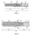
- FIGS. 4 to 9are detailed longitudinal cross-sectional views of delivery wire assemblies, according to various embodiments, wherein the outside sleeve has been omitted for clarity.
- FIG. 1illustrates an occlusive coil delivery system 10 according to one embodiment of the invention.
- the system 10includes a number of subcomponents or sub-systems, including a delivery catheter 100 , a delivery wire assembly 200 , an occlusive coil 300 , and a power supply 400 .
- the delivery catheter 100includes a proximal end 102 , a distal end 104 , and a lumen 106 extending between the proximal and distal ends 102 , 104 .
- the lumen 106 of the delivery catheter 100is sized to accommodate axial movement of the delivery wire assembly 200 . Further, the lumen 106 is sized for the passage of a guidewire (not shown), which may optionally be used to properly guide the delivery catheter 100 to the appropriate delivery site.
- the delivery catheter 100may include a braided-shaft construction of stainless steel flat wire that is encapsulated or surrounded by a polymer coating.
- HYDROLENE®is a polymer coating that may be used to cover the exterior portion of the delivery catheter 100 .
- the system 10is not limited to a particular construction or type of delivery catheter 100 and other constructions known to those skilled in the art may be used for the delivery catheter 100 .
- the inner lumen 106is advantageously coated with a lubricious coating such as PTFE to reduce frictional forces between the delivery catheter 100 and the respective delivery wire assembly 200 and occlusive coil 300 being moved axially within the lumen 106 .
- the delivery catheter 100may include one or more optional marker bands 108 formed from a radiopaque material that can be used to identify the location of the delivery catheter 100 within the patient's vasculature system using imaging technology (e.g., fluoroscope imaging).
- the length of the delivery catheter 100may vary depending on the particular application, but generally is around 150 cm in length. Of course, other lengths of the delivery catheter 100 may be used with the system 10 described herein.
- the delivery catheter 100may include a distal end 104 that is straight as illustrated in FIG. 1 .
- the distal end 104may be pre-shaped into a specific geometry or orientation.
- the distal end 104may be shaped into a “C” shape, an “S” shape, a “J” shape, a 45° bend, a 90° bend.
- the size of the lumen 106may vary depending on the size of the respective delivery wire assembly 200 and occlusive coil 300 , but generally the diameter lumen 106 of the delivery catheter 100 (I.D. of delivery catheter 100 ) is less than about 0.02 inches.
- the delivery catheter 100is known to those skilled in the art as a microcatheter. While not illustrated in FIG. 1 , the delivery catheter 100 may be utilized with a separate guide catheter (not shown) that aids in guiding the delivery catheter 100 to the appropriate location within the patient's vasculature.
- the system 10includes a delivery wire assembly 200 configured for axial movement within the lumen 106 of the delivery catheter 100 .
- the delivery wire assembly 200generally includes a proximal end 202 and a distal end 204 .
- the delivery wire assembly 200includes a delivery wire conduit 213 , which has a proximal tubular portion 206 and a distal coil portion 208 .
- the proximal tubular portion 206may be formed from, for example, a flexible stainless steel hypotube.
- the distal coil portion 208may be formed from, for example, stainless steel wire.
- the distal coil portion 208may be bonded to the proximal tubular portion 206 in an end-to-end arrangement.
- the delivery wire assembly 200further includes a core wire 210 that extends from the proximal end 202 of the delivery wire assembly 200 to a location that is distal with respect to the distal end 204 of the delivery wire assembly 200 .
- the core wire 210is disposed within a conduit lumen 212 that extends within an interior portion of the delivery wire conduit 213 .
- the core wire 210is formed from an electrically conductive material such as stainless steel wire.
- the proximal end 214 of the core wire 210(shown in phantom) is electrically coupled to an electrical contact 216 located at the proximal end 202 of the delivery wire assembly 200 .
- the electrical contact 216is configured to interface with a corresponding electrical contact (not shown) in the power supply 400 .
- a portion of the core wire 210is advantageously coated with an insulative coating 218 .
- the insulative coating 218may include polyimide.
- the entire length of the core wire 210is coated with an insulative coating 218 , except for the proximal end 214 of the core wire 210 that contacts the electrical contact 216 , and a small region 220 located in a portion of the core wire 210 that extends distally with respect to the distal end 204 of the delivery wire assembly 200 .
- This latter, “bare” portion of the core wire 210forms the electrolytic detachment zone 220 , which dissolves upon application of electrical current from the power supply 400 .
- the occlusive coil 300includes a proximal end 302 , a distal end 304 , and a lumen 306 extending there between.
- the occlusive coil 300is generally made from a biocompatible metal such as platinum or a platinum alloy (e.g., platinum-tungsten alloy).
- the occlusive coil 300generally includes a straight configuration (as illustrated in FIG. 1 ) when the occlusive coil 300 is loaded within the delivery catheter 100 .
- the occlusive coil 300Upon release, the occlusive coil 300 generally takes a secondary shape which may include two-dimensional or three-dimensional configurations such as that illustrated in FIG. 3 .
- the occlusive coil 300includes a plurality of coil windings 308 .
- the coil windings 308are generally helical about a central axis disposed along the lumen 306 of the occlusive coil 300 .
- the occlusive coil 300may have a closed pitch configuration as illustrated in FIG. 1 .
- the system 10 described hereinmay be used with occlusive coils 300 or other occlusive structures having a variety of configurations, and is not limited to occlusive coils 300 having a certain size or configuration.
- the distal end 222 of the core wire 210is connected to the proximal end 302 of the occlusive coil 300 at a junction 250 .
- Various techniques and devicescan be used to connect the core wire 210 to the occlusive coil 300 , including laser melting, and laser tack, spot, and continuous welding. It is preferable to apply an adhesive 240 to cover the junction 250 formed between the distal end 222 of the core wire 210 and the proximal end 302 of the occlusion coil 300 .
- the adhesive 240may include an epoxy material which is cured or hardened through the application of heat or UV radiation.
- the adhesive 240may include a thermally cured, two-part epoxy such as EPO-TEK® 353ND-4 available from Epoxy Technology, Inc., 14 Fortune Drive, Billerica, Mass.
- the adhesive 240encapsulates the junction 250 and increases its mechanical stability.
- the system 10further includes a power supply 400 for supplying direct current to the core wire 210 , which contains the electrolytic detachment zone 220 .
- a power supply 400for supplying direct current to the core wire 210 , which contains the electrolytic detachment zone 220 .
- an electrically conductive fluidincluding a physiological fluid such as blood, or an electrically conductive flushing solution such as saline
- activation of the power supply 400causes electrical current to flow in a circuit including the electrical contact 216 , the core wire 210 , the electrolytic detachment zone 220 , and a return electrode (not shown—typically a needle attached to the patient's skin).
- the sacrificial electrolytic detachment zone 220dissolves, and the occlusive coil 300 separates form the core wire 210 .
- the power supply 400preferably includes an onboard energy source, such as batteries (e.g., a pair of AAA batteries), along with drive circuitry 402 .
- the drive circuitry 402may include one or more microcontrollers or processors configured to output a driving current.
- the power supply 400 illustrated in FIG. 1includes a receptacle 404 configured to receive and mate with the proximal end 202 of the delivery wire assembly 200 . Upon insertion of the proximal end 202 into the receptacle 404 , the electrical contact 216 disposed on the delivery wire assembly 200 electrically couple with corresponding contacts (not shown) located in the power supply 400 .
- a visual indicator 406(e.g., LED light) is used to indicate when the proximal end 202 of delivery wire assembly 200 has been properly inserted into the power supply 400 .
- Another visual indicator 407is activated if the onboard energy source needs to be recharged or replaced.
- the power supply 400includes an activation trigger or button 408 that is depressed by the user to apply the electrical current to the sacrificial electrolytic detachment zone 220 . Once the activation trigger 408 has been activated, the driver circuitry 402 automatically supplies current until detachment occurs.
- the drive circuitry 402typically operates by applying a substantially constant current, e.g., around 1.5 mA.
- the power supply 400may include optional detection circuitry 410 that is configured to detect when the occlusive coil 300 has detached from the core wire 210 .
- the detection circuitry 410may identify detachment based upon a measured impedance value.
- a visual indicator 412may indicate when the power supply 400 is being supplied to the current to the sacrificial electrolytic detachment zone 220 .
- Another visual indicator 414may indicate when the occlusive coil 300 has detached from the core wire 210 .
- an audible signale.g., beep
- tactile signale.g., vibration or buzzer
- the detection circuitry 410may be configured to disable the drive circuitry 402 upon sensing detachment of the occlusive coil 300 .
- the power supply 400may also contain another visual indicator 416 that indicates to the operator when non-bipolar delivery wire assembly is inserted into the power supply 400 .
- non-bipolar delivery wire assembliesuse a separate return electrode that typically is in the form of a needle that was inserted into the groin area of the patient.
- the power supply 400is configured to detect when a non-bipolar delivery wire assembly has been inserted. Under such situations, the visual indicator 416 (e.g., LED) is turned on and the user is advised to insert the separate return electrode (not shown in FIG. 1 ) into a port 418 located on the power supply 400 .
- the visual indicator 416e.g., LED
- the core wire 210forms a first conductive path 242 between the electrical contact 216 and the electrolytic detachment zone 220 .
- This first conductive path 242may comprise the anode (+) of the electrolytic circuit when the delivery wire assembly 200 is operatively coupled to the power supply 400 .
- a second conductive path 244is formed by the proximal tubular portion 206 and a distal coil portion 208 of the delivery wire conduit 213 .
- the second conductive path 244is electrically isolated from the first conductive path 242 .
- the second conductive path 244may comprise the cathode ( ⁇ ) or ground electrode for the electrical circuit.
- a ground contact 246 for the second conductive path 244may be disposed on a proximal end of the tubular portion 206 of the delivery wire conduit 213 .
- the ground contact 246is simply an exposed portion of the tubular portion 206 since the tubular portion 206 is part of the second conductive path 244 .
- a proximal portion of the tubular portion 206 that is adjacent to the electrical contact 216may be covered with an insulative coating 207 such as polyimide as illustrated in FIG. 2 .
- An exposed region of the tubular portion 206 that does not have the insulative coatingmay form the ground contact 246 .
- the ground contact 246may be a ring type electrode or other contact that is formed on the exterior of the tubular portion 206 .
- the ground contact 246is configured to interface with a corresponding electrical contact (not shown) in the power supply 400 when the proximal end 202 of the delivery wire assembly 200 is inserted into the power supply 400 .
- the ground contact 246 of the second conductive path 244is, of course, electrically isolated with respect to the electrical contact 216 of the first conductive path 242 .
- FIG. 2illustrates a cross-sectional view of the delivery wire assembly 200 according to one embodiment. Similar elements of this embodiment are identified with the same reference numbers as discussed above with respect to FIG. 1 .
- the delivery wire assembly 200includes a proximal end 202 and a distal end 204 and measures between around 184 cm to around 186 cm in length.
- the delivery wire assembly 200includes a delivery wire conduit 213 with a proximal tubular portion 206 and a distal coil portion 208 .
- the proximal tubular portion 206may be formed from stainless steel hypotube having an outer diameter (OD) of 0.013 inches and inner diameter (ID) of 0.005 inches.
- the length of the hypotube sectionmay be between around 140 cm to around 150 cm, although other lengths may also be used.
- the proximal end 252 of the proximal tubular portion 206tapers down to relatively small cross section.
- the OD of the proximal end 252 of the proximal tubular portion 206is approximately 0.009 inches, whereas the OD of the rest of the proximal tubular portion 206 is approximately 0.013 inches.
- the IDremains constant at 0.005 inches throughout the length of the proximal tubular portion 206 .
- the proximal end 252 of the proximal tubular portion 206is covered, both externally and at least partially in the conduit lumen 212 , with an insulation layer 254 .
- connection tube 256is disposed like a connection collar around the insulation layer 254 , which separates it electrically from the proximal tubular portion 206 .
- the connection tube 256has an OD of approximately 0.013 inches to match the main body of the proximal tubular portion 206 , and an ID of 0.0100, slightly larger than the OD of the proximal end 252 of the proximal tubular portion 206 .
- the connection tube 256is electrically and physically connected to the core wire 210 with a silver epoxy 258 , which is applied to the connection tube 256 , the insulation 254 covered proximal end 252 of the proximal tubular portion 206 , and that end of the core wire 210 .
- connection tube 256is also physically connected to the proximal end 252 of the proximal tubular portion 206 with the silver epoxy 258 and a non-conductive adhesive 240 .
- the connection tube 256 and the cured silver epoxy 258form the electrical contact 216 , which along with the core wire 210 form the first conductive path 242 and the anode.
- the insulation layer 254electrically separates the first conductive path 242 from the proximal tubular portion 206 , which is part of the second (return) conductive path 244 .
- connection tube 256has been replaced with a connection coil 260 , which forms the connection collar.
- the connection coil 260has dimensions similar to the connection tube 256 and it has open pitch coils. The pitch of the coils is around 5-40%, preferably around 10-30%, and more preferably around 10-20%.
- the connection coil 260increases the flexibility of the proximal end 252 of the proximal tubular portion 206 , which in turn increases its structural integrity.
- the proximal tubular portion 206does not taper down to a smaller cross section.
- a proximal contact tube 262is seated in the conduit lumen 212 , forming a junction 264 , and the core wire 210 is threaded through the proximal contact tube 262 .
- the proximal contact tube 262is an elongate body that may be made of Nitinol or stainless steel. Alternatively, the proximal contact tube 262 may be a tubular body formed from stainless steel coils, as depicted in FIG. 8 .
- the proximal contact tube 262is connected to the proximal tubular portion 206 with non-conductive adhesive 240 near the junction 264 .
- the proximal contact tube 262is also connected to the core wire 210 with a silver epoxy 258 where the core wire 210 extends out of the proximal end of the proximal contact tube 262 .
- the proximal contact tube 262 and the silver epoxy 258form the electrical contact 216 , which along with the core wire 210 form the first conductive path 242 and the anode.
- An insulation layer 254electrically separates the proximal contact tube 262 from the proximal tubular portion 206 .
- Embedded in the adhesive 240 around the junction 264is a coil collar 266 , which increases the flexibility of the junction 264 , which in turn increases its structural integrity.
- the coilhas an open pitch of around 10% to 15%.
- the coil collar 266is connected to the proximal tubular portion 206 with a soldering bond 268 , which also connects the proximal contact tube 262 with the proximal tubular portion 206 .
- FIG. 7The embodiment depicted in FIG. 7 is similar to that depicted in FIG. 6 , except that the proximal contact tube 262 has been replaced with a proximal contact mandrel 270 .
- the core wire 210is joined to the distal end of the proximal contact mandrel 270 with a conductive bond 272 , such as that formed by welding or soldering.
- the function of the structure and function of the coil collar 266remains unchanged in this embodiment.
- the inner surface of the proximal end 252 of the proximal tubular portion 206 of the delivery wire conduit 213flares out in a proximal direction such that the ID of the proximal end 252 of the proximal tubular portion 206 is larger than the ID of the rest of the proximal tubular portion 206 .
- the flaring of the inner surface at the proximal end 252reduces stress concentration at the junction 264 where the proximal contact tube 262 is seated in the conduit lumen 212 , thereby reducing the tendency of buckling when the junction 264 is compressed.
- An adhesive 240seals and bonds the junction 264 .
- a distal coil portion 208is bonded in end-to-end fashion to the distal face of the proximal tubular portion 206 .
- the bondingmay be accomplished using a weld or other bond.
- the distal coil portion 208may have a length of around 39 cm to around 41 cm in length.
- the distal coil portion 208may comprise a coil of 0.0025 inches ⁇ 0.006 inches.
- the first dimensiongenerally refers to the OD of the coil wire that forms the coil.
- the latter dimensiongenerally refers to the internal mandrel used to wind the coil wire around to form the plurality of coil winds and is the nominal ID of the coil.
- One or more marker coils 205 of the distal coil portion 208may be formed from a radiopaque material (illustrated as solid marker coils 205 in distal coil portion 208 ).
- the distal coil portion 208may include a segment of stainless steel coil (e.g., 3 cm in length), followed by a segment of platinum coil (which is radiopaque and also 3 mm in length), followed by a segment of stainless steel coil (e.g., 37 cm in length), and so on and so forth.
- An outer sleeve 263 or jacketsurrounds a portion of the proximal tubular portion 206 and a portion of the distal coil portion 208 of the delivery wire conduit 213 .
- the outer sleeve 263covers the interface or joint formed between the proximal tubular portion 206 and the distal coil portion 208 .
- the outer sleeve 263may have a length of around 50 cm to around 54 cm.
- the outer sleeve 263may be formed from a polyether block amide plastic material (e.g., PEBAX 7233 lamination).
- the outer sleeve 263may include a lamination of PEBAX and HYDROLENE® that may be heat laminated to the delivery wire assembly 200 .
- the OD of the outer sleeve 263may be less than 0.02 inches and advantageously less than 0.015 inches.
- the core wire 210which runs through the delivery wire conduit 213 , terminates at electrical contact 216 at one end and extends distally with respect to the distal coil portion 208 of the delivery wire conduit 213 .
- the core wire 210is coated with an insulative coating 218 such as polyimide except at the electrolytic detachment zone 220 and the proximal segment coupled to the electrical contact 216 .
- the electrolytic detachment zone 220is located several centimeters (e.g., about 0.02 mm to about 0.2 mm) distally with respect to the distal end of the distal coil portion 208 .
- the core wire 210may have an OD of around 0.00175 inches.
- FIG. 3illustrates one exemplary configuration of an occlusive coil 300 in a natural state.
- the occlusive coil 300transforms from the straight configuration illustrated in, for instance, FIG. 1 into a secondary shape.
- the secondary shapedmay include both two and three dimensional shapes of a wide variety.
- FIG. 3is just one example of a secondary shape of an occlusive coil 300 and other shapes and configurations are contemplated to fall within the scope of the invention.
- the occlusive coil 300may incorporate synthetic fibers over all or a portion of the occlusive coil 300 as is known in the art. These fibers may be attached directly to coil windings 308 or the fibers may be integrated into the occlusive coil 300 using a weave or braided configuration.
Landscapes
- Health & Medical Sciences (AREA)
- Surgery (AREA)
- Life Sciences & Earth Sciences (AREA)
- Heart & Thoracic Surgery (AREA)
- Nuclear Medicine, Radiotherapy & Molecular Imaging (AREA)
- Vascular Medicine (AREA)
- Engineering & Computer Science (AREA)
- Biomedical Technology (AREA)
- Reproductive Health (AREA)
- Medical Informatics (AREA)
- Molecular Biology (AREA)
- Animal Behavior & Ethology (AREA)
- General Health & Medical Sciences (AREA)
- Public Health (AREA)
- Veterinary Medicine (AREA)
- Surgical Instruments (AREA)
Abstract
Description
Claims (12)
Priority Applications (2)
| Application Number | Priority Date | Filing Date | Title |
|---|---|---|---|
| US12/758,528US8398671B2 (en) | 2009-04-16 | 2010-04-12 | Electrical contact for occlusive device delivery system |
| US13/791,583US9314250B2 (en) | 2009-04-16 | 2013-03-08 | Electrical contact for occlusive device delivery system |
Applications Claiming Priority (3)
| Application Number | Priority Date | Filing Date | Title |
|---|---|---|---|
| US17004309P | 2009-04-16 | 2009-04-16 | |
| US18425409P | 2009-06-04 | 2009-06-04 | |
| US12/758,528US8398671B2 (en) | 2009-04-16 | 2010-04-12 | Electrical contact for occlusive device delivery system |
Related Child Applications (1)
| Application Number | Title | Priority Date | Filing Date |
|---|---|---|---|
| US13/791,583Continuation-In-PartUS9314250B2 (en) | 2009-04-16 | 2013-03-08 | Electrical contact for occlusive device delivery system |
Publications (2)
| Publication Number | Publication Date |
|---|---|
| US20100268252A1 US20100268252A1 (en) | 2010-10-21 |
| US8398671B2true US8398671B2 (en) | 2013-03-19 |
Family
ID=42272123
Family Applications (1)
| Application Number | Title | Priority Date | Filing Date |
|---|---|---|---|
| US12/758,528Active2030-12-08US8398671B2 (en) | 2009-04-16 | 2010-04-12 | Electrical contact for occlusive device delivery system |
Country Status (2)
| Country | Link |
|---|---|
| US (1) | US8398671B2 (en) |
| WO (1) | WO2010120694A1 (en) |
Cited By (36)
| Publication number | Priority date | Publication date | Assignee | Title |
|---|---|---|---|---|
| US20130184743A1 (en)* | 2009-04-16 | 2013-07-18 | Stryker Nv Operations Limited | Electrical contact for occlusive device delivery system |
| US9326774B2 (en) | 2012-08-03 | 2016-05-03 | Covidien Lp | Device for implantation of medical devices |
| US9717503B2 (en) | 2015-05-11 | 2017-08-01 | Covidien Lp | Electrolytic detachment for implant delivery systems |
| US9808256B2 (en) | 2014-08-08 | 2017-11-07 | Covidien Lp | Electrolytic detachment elements for implant delivery systems |
| US9808599B2 (en) | 2013-12-20 | 2017-11-07 | Microvention, Inc. | Device delivery system |
| US9814466B2 (en) | 2014-08-08 | 2017-11-14 | Covidien Lp | Electrolytic and mechanical detachment for implant delivery systems |
| US10130372B2 (en) | 2014-04-30 | 2018-11-20 | Cerus Endovascular Limited | Occlusion Device |
| US10828039B2 (en) | 2016-06-27 | 2020-11-10 | Covidien Lp | Electrolytic detachment for implantable devices |
| US10828037B2 (en) | 2016-06-27 | 2020-11-10 | Covidien Lp | Electrolytic detachment with fluid electrical connection |
| US10869672B2 (en) | 2016-03-11 | 2020-12-22 | Cents Endovascular Limited | Occlusion device |
| US10905430B2 (en) | 2018-01-24 | 2021-02-02 | DePuy Synthes Products, Inc. | Aneurysm device and delivery system |
| US10939915B2 (en) | 2018-05-31 | 2021-03-09 | DePuy Synthes Products, Inc. | Aneurysm device and delivery system |
| US11051822B2 (en) | 2016-06-28 | 2021-07-06 | Covidien Lp | Implant detachment with thermal activation |
| US11058430B2 (en) | 2018-05-25 | 2021-07-13 | DePuy Synthes Products, Inc. | Aneurysm device and delivery system |
| US11076860B2 (en) | 2014-03-31 | 2021-08-03 | DePuy Synthes Products, Inc. | Aneurysm occlusion device |
| US11076861B2 (en) | 2018-10-12 | 2021-08-03 | DePuy Synthes Products, Inc. | Folded aneurysm treatment device and delivery method |
| US11123077B2 (en) | 2018-09-25 | 2021-09-21 | DePuy Synthes Products, Inc. | Intrasaccular device positioning and deployment system |
| US11134953B2 (en) | 2019-02-06 | 2021-10-05 | DePuy Synthes Products, Inc. | Adhesive cover occluding device for aneurysm treatment |
| US11154302B2 (en) | 2014-03-31 | 2021-10-26 | DePuy Synthes Products, Inc. | Aneurysm occlusion device |
| US11272939B2 (en) | 2018-12-18 | 2022-03-15 | DePuy Synthes Products, Inc. | Intrasaccular flow diverter for treating cerebral aneurysms |
| US11278292B2 (en) | 2019-05-21 | 2022-03-22 | DePuy Synthes Products, Inc. | Inverting braided aneurysm treatment system and method |
| US11337706B2 (en) | 2019-03-27 | 2022-05-24 | DePuy Synthes Products, Inc. | Aneurysm treatment device |
| US11406404B2 (en) | 2020-02-20 | 2022-08-09 | Cerus Endovascular Limited | Clot removal distal protection methods |
| US11406392B2 (en) | 2018-12-12 | 2022-08-09 | DePuy Synthes Products, Inc. | Aneurysm occluding device for use with coagulating agents |
| US11413046B2 (en) | 2019-05-21 | 2022-08-16 | DePuy Synthes Products, Inc. | Layered braided aneurysm treatment device |
| US11457926B2 (en) | 2019-12-18 | 2022-10-04 | DePuy Synthes Products, Inc. | Implant having an intrasaccular section and intravascular section |
| US11471162B2 (en) | 2015-12-07 | 2022-10-18 | Cerus Endovascular Limited | Occlusion device |
| US11497504B2 (en) | 2019-05-21 | 2022-11-15 | DePuy Synthes Products, Inc. | Aneurysm treatment with pushable implanted braid |
| US11583282B2 (en) | 2019-05-21 | 2023-02-21 | DePuy Synthes Products, Inc. | Layered braided aneurysm treatment device |
| US11583288B2 (en) | 2018-08-08 | 2023-02-21 | DePuy Synthes Products, Inc. | Delivery of embolic braid |
| US11596412B2 (en) | 2018-05-25 | 2023-03-07 | DePuy Synthes Products, Inc. | Aneurysm device and delivery system |
| US11602350B2 (en) | 2019-12-05 | 2023-03-14 | DePuy Synthes Products, Inc. | Intrasaccular inverting braid with highly flexible fill material |
| US11607226B2 (en) | 2019-05-21 | 2023-03-21 | DePuy Synthes Products, Inc. | Layered braided aneurysm treatment device with corrugations |
| US11672543B2 (en) | 2017-02-23 | 2023-06-13 | DePuy Synthes Products, Inc. | Aneurysm method and system |
| US11672542B2 (en) | 2019-05-21 | 2023-06-13 | DePuy Synthes Products, Inc. | Aneurysm treatment with pushable ball segment |
| US11812971B2 (en) | 2017-08-21 | 2023-11-14 | Cerus Endovascular Limited | Occlusion device |
Families Citing this family (14)
| Publication number | Priority date | Publication date | Assignee | Title |
|---|---|---|---|---|
| US8777979B2 (en) | 2006-04-17 | 2014-07-15 | Covidien Lp | System and method for mechanically positioning intravascular implants |
| JP5230602B2 (en) | 2006-04-17 | 2013-07-10 | タイコ ヘルスケア グループ リミテッド パートナーシップ | System and method for mechanically positioning an endovascular implant |
| CA2710781C (en) | 2007-12-21 | 2016-09-27 | Microvention, Inc. | A system and method of detecting implant detachment |
| JP5366974B2 (en) | 2007-12-21 | 2013-12-11 | マイクロベンション インコーポレイテッド | System and method for determining the position of a separation zone of a separable implant |
| WO2010117883A1 (en)* | 2009-04-06 | 2010-10-14 | Boston Scientific Scimed, Inc. | Delivery wire for occlusive device delivery system |
| US9814562B2 (en) | 2009-11-09 | 2017-11-14 | Covidien Lp | Interference-relief type delivery detachment systems |
| US8945171B2 (en) | 2011-09-29 | 2015-02-03 | Covidien Lp | Delivery system for implantable devices |
| US8795313B2 (en) | 2011-09-29 | 2014-08-05 | Covidien Lp | Device detachment systems with indicators |
| US9579104B2 (en) | 2011-11-30 | 2017-02-28 | Covidien Lp | Positioning and detaching implants |
| CN110169802B (en) | 2013-03-15 | 2022-07-08 | 柯惠有限合伙公司 | Delivery and detachment mechanism for vascular implants |
| EP4151164A1 (en) | 2014-04-11 | 2023-03-22 | Microvention, Inc. | Implant delivery system |
| US12114863B2 (en) | 2018-12-05 | 2024-10-15 | Microvention, Inc. | Implant delivery system |
| CN113855136A (en)* | 2020-06-30 | 2021-12-31 | 微创神通医疗科技(上海)有限公司 | End structure of pushing rod of electrolytic release spring ring, release system and embolism system of end structure |
| CN114246711A (en)* | 2021-12-02 | 2022-03-29 | 微创神通医疗科技(上海)有限公司 | Push rod, releasing device and medical device |
Citations (50)
| Publication number | Priority date | Publication date | Assignee | Title |
|---|---|---|---|---|
| US4994069A (en) | 1988-11-02 | 1991-02-19 | Target Therapeutics | Vaso-occlusion coil and method |
| US5122136A (en)* | 1990-03-13 | 1992-06-16 | The Regents Of The University Of California | Endovascular electrolytically detachable guidewire tip for the electroformation of thrombus in arteries, veins, aneurysms, vascular malformations and arteriovenous fistulas |
| US5226911A (en) | 1991-10-02 | 1993-07-13 | Target Therapeutics | Vasoocclusion coil with attached fibrous element(s) |
| US5304194A (en) | 1991-10-02 | 1994-04-19 | Target Therapeutics | Vasoocclusion coil with attached fibrous element(s) |
| US5382259A (en) | 1992-10-26 | 1995-01-17 | Target Therapeutics, Inc. | Vasoocclusion coil with attached tubular woven or braided fibrous covering |
| US5423829A (en)* | 1993-11-03 | 1995-06-13 | Target Therapeutics, Inc. | Electrolytically severable joint for endovascular embolic devices |
| US5522836A (en)* | 1994-06-27 | 1996-06-04 | Target Therapeutics, Inc. | Electrolytically severable coil assembly with movable detachment point |
| US5549624A (en) | 1994-06-24 | 1996-08-27 | Target Therapeutics, Inc. | Fibered vasooclusion coils |
| US5578074A (en)* | 1994-12-22 | 1996-11-26 | Target Therapeutics, Inc. | Implant delivery method and assembly |
| US5582619A (en) | 1995-06-30 | 1996-12-10 | Target Therapeutics, Inc. | Stretch resistant vaso-occlusive coils |
| US5685322A (en)* | 1993-01-29 | 1997-11-11 | Cardima, Inc. | Intravascular system for treating arrhythmia |
| US5690666A (en) | 1992-11-18 | 1997-11-25 | Target Therapeutics, Inc. | Ultrasoft embolism coils and process for using them |
| EP0826342A1 (en) | 1996-08-30 | 1998-03-04 | Target Therapeutics, Inc. | Electrolytically deployable braided vaso-occlusion device |
| US5743905A (en) | 1995-07-07 | 1998-04-28 | Target Therapeutics, Inc. | Partially insulated occlusion device |
| US5853418A (en) | 1995-06-30 | 1998-12-29 | Target Therapeutics, Inc. | Stretch resistant vaso-occlusive coils (II) |
| US5919187A (en) | 1990-03-13 | 1999-07-06 | The Regents Of The University Of California | Method and apparatus for endovascular thermal thrombosis and thermal cancer treatment |
| WO1999042038A1 (en) | 1998-02-18 | 1999-08-26 | Boston Scientific Limited | Vaso-occlusive member assembly with multiple detaching points |
| US5984929A (en) | 1997-08-29 | 1999-11-16 | Target Therapeutics, Inc. | Fast detaching electronically isolated implant |
| US6059779A (en) | 1995-04-28 | 2000-05-09 | Target Therapeutics, Inc. | Delivery catheter for electrolytically detachable implant |
| US6077260A (en) | 1998-02-19 | 2000-06-20 | Target Therapeutics, Inc. | Assembly containing an electrolytically severable joint for endovascular embolic devices |
| US6102933A (en) | 1997-02-28 | 2000-08-15 | The Regents Of The University Of California | Release mechanism utilizing shape memory polymer material |
| US6277125B1 (en) | 1998-10-05 | 2001-08-21 | Cordis Neurovascular, Inc. | Embolic coil deployment system with retaining jaws |
| US6280457B1 (en) | 1999-06-04 | 2001-08-28 | Scimed Life Systems, Inc. | Polymer covered vaso-occlusive devices and methods of producing such devices |
| US20020151883A1 (en)* | 1990-03-13 | 2002-10-17 | Guido Guglielmi | Method and apparatus for fast electrolyitic detachment of an implant |
| US6537293B1 (en) | 1997-03-07 | 2003-03-25 | Board Of Regents, The University Of Texas System | Method of intracranial vascular embolotherapy using self anchoring coils |
| US6575965B1 (en) | 1997-03-06 | 2003-06-10 | The Regents Of The University Of California | Medical devices utilizing optical fibers for simultaneous power, communications and control |
| US20030120300A1 (en) | 2001-12-20 | 2003-06-26 | Scimed Life Systems, Inc. | Detachable device with electrically responsive element |
| US6589230B2 (en) | 1994-12-30 | 2003-07-08 | Target Therapeutics, Inc. | System for detaching an occlusive device within a mammalian body using a solderless, electrolytically severable joint |
| US20040002732A1 (en) | 2002-06-27 | 2004-01-01 | Clifford Teoh | Stretch-resistant vaso-occlusive assembly with multiple detaching points |
| US20040010243A1 (en) | 2000-01-28 | 2004-01-15 | William Cook Europe Aps | Endovascular medical device with plurality of wires |
| DE10325130B3 (en) | 2003-06-04 | 2004-09-09 | Czerwinski, Frank, Dr. | Device for implanting occlusion helixes into hollow body chambers comprises a guiding and a detaching unit having a connecting part arranged on its distal end |
| WO2005070308A2 (en) | 2004-01-21 | 2005-08-04 | Dendron Gmbh | Device for implanting electrically isolated occlusion helixes |
| US20060135986A1 (en) | 2004-12-22 | 2006-06-22 | Scimed Life Systems, Inc. | Vaso-occlusive device having pivotable coupling |
| US20060271097A1 (en) | 2005-05-31 | 2006-11-30 | Kamal Ramzipoor | Electrolytically detachable implantable devices |
| US20060282112A1 (en) | 2005-06-09 | 2006-12-14 | Stephen Griffin | Method and apparatus for enhanced electrolytic detachment |
| US20070055302A1 (en) | 2005-06-14 | 2007-03-08 | Boston Scientific Scimed, Inc. | Vaso-occlusive delivery device with kink resistant, flexible distal end |
| US20070073334A1 (en)* | 2005-09-29 | 2007-03-29 | Kamal Ramzipoor | Combined electrolytic and mechanical separation background |
| US7198613B2 (en) | 2000-02-09 | 2007-04-03 | Micrus Endovascular Corporation | Apparatus for deployment of micro-coil using a catheter |
| US20070123927A1 (en) | 2005-11-30 | 2007-05-31 | Farnan Robert C | Embolic device delivery system |
| WO2008064206A2 (en) | 2006-11-20 | 2008-05-29 | Boston Scientific Scimed, Inc. | Mechanically detachable vaso-occlusive device |
| WO2008085606A1 (en) | 2006-11-20 | 2008-07-17 | Boston Scientific Scimed, Inc. | Mechanically detachable vaso-occlusive device |
| WO2008144587A2 (en) | 2007-05-18 | 2008-11-27 | Boston Scientific Scimed, Inc. | Medical implant detachment systems |
| US20090018653A1 (en) | 2007-07-13 | 2009-01-15 | Boston Scientific Scimed, Inc. | Hybrid and portable power supplies for electrolytically detaching implantable medical devices |
| US20090024154A1 (en) | 2007-07-20 | 2009-01-22 | Michael Williams | Power supply using time varying signal for electrolytically detaching implantable device |
| US20090062812A1 (en)* | 2007-07-27 | 2009-03-05 | Microvention, Inc. | Detachable Coil Incorporating Stretch Resistance |
| US20090143786A1 (en) | 2007-12-03 | 2009-06-04 | Boston Scientific Scimed, Inc. | Implantable device with electrolytically detachable junction having multiple fine wires and method of introduction |
| US20090177261A1 (en) | 2008-01-04 | 2009-07-09 | Boston Scientific Scimed, Inc. | Detachment mechanisms for implantable devices |
| US20100094395A1 (en) | 2008-10-13 | 2010-04-15 | Boston Scientific Scimed, Inc. | Vaso-occlusive coil delivery system |
| US7862602B2 (en) | 2005-11-02 | 2011-01-04 | Biosensors International Group, Ltd | Indirect-release electrolytic implant delivery systems |
| US7921848B2 (en) | 1995-06-07 | 2011-04-12 | Conceptus, Inc. | Contraceptive transcervical fallopian tube occlusion devices and methods |
- 2010
- 2010-04-12USUS12/758,528patent/US8398671B2/enactiveActive
- 2010-04-12WOPCT/US2010/030753patent/WO2010120694A1/enactiveApplication Filing
Patent Citations (61)
| Publication number | Priority date | Publication date | Assignee | Title |
|---|---|---|---|---|
| US4994069A (en) | 1988-11-02 | 1991-02-19 | Target Therapeutics | Vaso-occlusion coil and method |
| US5122136A (en)* | 1990-03-13 | 1992-06-16 | The Regents Of The University Of California | Endovascular electrolytically detachable guidewire tip for the electroformation of thrombus in arteries, veins, aneurysms, vascular malformations and arteriovenous fistulas |
| US20020151883A1 (en)* | 1990-03-13 | 2002-10-17 | Guido Guglielmi | Method and apparatus for fast electrolyitic detachment of an implant |
| US5919187A (en) | 1990-03-13 | 1999-07-06 | The Regents Of The University Of California | Method and apparatus for endovascular thermal thrombosis and thermal cancer treatment |
| US5304194A (en) | 1991-10-02 | 1994-04-19 | Target Therapeutics | Vasoocclusion coil with attached fibrous element(s) |
| US5226911A (en) | 1991-10-02 | 1993-07-13 | Target Therapeutics | Vasoocclusion coil with attached fibrous element(s) |
| US5382259A (en) | 1992-10-26 | 1995-01-17 | Target Therapeutics, Inc. | Vasoocclusion coil with attached tubular woven or braided fibrous covering |
| US5690666A (en) | 1992-11-18 | 1997-11-25 | Target Therapeutics, Inc. | Ultrasoft embolism coils and process for using them |
| US5685322A (en)* | 1993-01-29 | 1997-11-11 | Cardima, Inc. | Intravascular system for treating arrhythmia |
| US5423829A (en)* | 1993-11-03 | 1995-06-13 | Target Therapeutics, Inc. | Electrolytically severable joint for endovascular embolic devices |
| US5549624A (en) | 1994-06-24 | 1996-08-27 | Target Therapeutics, Inc. | Fibered vasooclusion coils |
| US5522836A (en)* | 1994-06-27 | 1996-06-04 | Target Therapeutics, Inc. | Electrolytically severable coil assembly with movable detachment point |
| US5578074A (en)* | 1994-12-22 | 1996-11-26 | Target Therapeutics, Inc. | Implant delivery method and assembly |
| US6589230B2 (en) | 1994-12-30 | 2003-07-08 | Target Therapeutics, Inc. | System for detaching an occlusive device within a mammalian body using a solderless, electrolytically severable joint |
| US6059779A (en) | 1995-04-28 | 2000-05-09 | Target Therapeutics, Inc. | Delivery catheter for electrolytically detachable implant |
| US7921848B2 (en) | 1995-06-07 | 2011-04-12 | Conceptus, Inc. | Contraceptive transcervical fallopian tube occlusion devices and methods |
| US5853418A (en) | 1995-06-30 | 1998-12-29 | Target Therapeutics, Inc. | Stretch resistant vaso-occlusive coils (II) |
| US5582619A (en) | 1995-06-30 | 1996-12-10 | Target Therapeutics, Inc. | Stretch resistant vaso-occlusive coils |
| US5743905A (en) | 1995-07-07 | 1998-04-28 | Target Therapeutics, Inc. | Partially insulated occlusion device |
| EP0826342A1 (en) | 1996-08-30 | 1998-03-04 | Target Therapeutics, Inc. | Electrolytically deployable braided vaso-occlusion device |
| US6102933A (en) | 1997-02-28 | 2000-08-15 | The Regents Of The University Of California | Release mechanism utilizing shape memory polymer material |
| US6575965B1 (en) | 1997-03-06 | 2003-06-10 | The Regents Of The University Of California | Medical devices utilizing optical fibers for simultaneous power, communications and control |
| US6537293B1 (en) | 1997-03-07 | 2003-03-25 | Board Of Regents, The University Of Texas System | Method of intracranial vascular embolotherapy using self anchoring coils |
| US5984929A (en) | 1997-08-29 | 1999-11-16 | Target Therapeutics, Inc. | Fast detaching electronically isolated implant |
| US6468266B1 (en) | 1997-08-29 | 2002-10-22 | Scimed Life Systems, Inc. | Fast detaching electrically isolated implant |
| WO1999042038A1 (en) | 1998-02-18 | 1999-08-26 | Boston Scientific Limited | Vaso-occlusive member assembly with multiple detaching points |
| US20030130689A1 (en) | 1998-02-18 | 2003-07-10 | Target Therapeutics, Inc. | Vaso-occlusive member assembly with multiple detaching points |
| US20020091380A1 (en) | 1998-02-19 | 2002-07-11 | Target Therapeutics, Inc. | Assembly containing an electrolytically severable joint for endovascular embolic devices |
| US6409721B1 (en) | 1998-02-19 | 2002-06-25 | Target Therapeutics, Inc. | Process for forming an occlusion in a body cavity |
| US6077260A (en) | 1998-02-19 | 2000-06-20 | Target Therapeutics, Inc. | Assembly containing an electrolytically severable joint for endovascular embolic devices |
| US6277125B1 (en) | 1998-10-05 | 2001-08-21 | Cordis Neurovascular, Inc. | Embolic coil deployment system with retaining jaws |
| US6280457B1 (en) | 1999-06-04 | 2001-08-28 | Scimed Life Systems, Inc. | Polymer covered vaso-occlusive devices and methods of producing such devices |
| US20040010243A1 (en) | 2000-01-28 | 2004-01-15 | William Cook Europe Aps | Endovascular medical device with plurality of wires |
| US20090299275A1 (en) | 2000-02-09 | 2009-12-03 | Micrus Corporation | Apparatus for deployment of micro-coil using a catheter |
| US7198613B2 (en) | 2000-02-09 | 2007-04-03 | Micrus Endovascular Corporation | Apparatus for deployment of micro-coil using a catheter |
| US20030120300A1 (en) | 2001-12-20 | 2003-06-26 | Scimed Life Systems, Inc. | Detachable device with electrically responsive element |
| WO2003053281A1 (en) | 2001-12-20 | 2003-07-03 | Scimed Life Systems, Inc. | Detachable device with electrically responsive element |
| US6953473B2 (en) | 2001-12-20 | 2005-10-11 | Boston Scientific Scimed, Inc. | Detachable device with electrically responsive element |
| US20040002733A1 (en) | 2002-06-27 | 2004-01-01 | Clifford Teoh | Integrated anchor coil in stretch-resistant vaso-occlusive coils |
| US20040002732A1 (en) | 2002-06-27 | 2004-01-01 | Clifford Teoh | Stretch-resistant vaso-occlusive assembly with multiple detaching points |
| DE10325130B3 (en) | 2003-06-04 | 2004-09-09 | Czerwinski, Frank, Dr. | Device for implanting occlusion helixes into hollow body chambers comprises a guiding and a detaching unit having a connecting part arranged on its distal end |
| WO2005070308A2 (en) | 2004-01-21 | 2005-08-04 | Dendron Gmbh | Device for implanting electrically isolated occlusion helixes |
| US20100076479A1 (en) | 2004-01-21 | 2010-03-25 | Hermann Monstadt | Device for implanting electrically isolated occlusion helixes |
| US20060135986A1 (en) | 2004-12-22 | 2006-06-22 | Scimed Life Systems, Inc. | Vaso-occlusive device having pivotable coupling |
| US20060271097A1 (en) | 2005-05-31 | 2006-11-30 | Kamal Ramzipoor | Electrolytically detachable implantable devices |
| US20060282112A1 (en) | 2005-06-09 | 2006-12-14 | Stephen Griffin | Method and apparatus for enhanced electrolytic detachment |
| US20070055302A1 (en) | 2005-06-14 | 2007-03-08 | Boston Scientific Scimed, Inc. | Vaso-occlusive delivery device with kink resistant, flexible distal end |
| US20070073334A1 (en)* | 2005-09-29 | 2007-03-29 | Kamal Ramzipoor | Combined electrolytic and mechanical separation background |
| US20110160835A1 (en) | 2005-11-02 | 2011-06-30 | Biosensors International Group, Ltd. | Indirect-release electrolytic implant delivery systems |
| US7862602B2 (en) | 2005-11-02 | 2011-01-04 | Biosensors International Group, Ltd | Indirect-release electrolytic implant delivery systems |
| US20070123927A1 (en) | 2005-11-30 | 2007-05-31 | Farnan Robert C | Embolic device delivery system |
| WO2008064206A2 (en) | 2006-11-20 | 2008-05-29 | Boston Scientific Scimed, Inc. | Mechanically detachable vaso-occlusive device |
| WO2008085606A1 (en) | 2006-11-20 | 2008-07-17 | Boston Scientific Scimed, Inc. | Mechanically detachable vaso-occlusive device |
| WO2008144587A2 (en) | 2007-05-18 | 2008-11-27 | Boston Scientific Scimed, Inc. | Medical implant detachment systems |
| US20090062726A1 (en)* | 2007-05-18 | 2009-03-05 | Bsoton Scientific Scimed, Inc. | Medical implant detachment systems and methods |
| US20090018653A1 (en) | 2007-07-13 | 2009-01-15 | Boston Scientific Scimed, Inc. | Hybrid and portable power supplies for electrolytically detaching implantable medical devices |
| US20090024154A1 (en) | 2007-07-20 | 2009-01-22 | Michael Williams | Power supply using time varying signal for electrolytically detaching implantable device |
| US20090062812A1 (en)* | 2007-07-27 | 2009-03-05 | Microvention, Inc. | Detachable Coil Incorporating Stretch Resistance |
| US20090143786A1 (en) | 2007-12-03 | 2009-06-04 | Boston Scientific Scimed, Inc. | Implantable device with electrolytically detachable junction having multiple fine wires and method of introduction |
| US20090177261A1 (en) | 2008-01-04 | 2009-07-09 | Boston Scientific Scimed, Inc. | Detachment mechanisms for implantable devices |
| US20100094395A1 (en) | 2008-10-13 | 2010-04-15 | Boston Scientific Scimed, Inc. | Vaso-occlusive coil delivery system |
Non-Patent Citations (9)
| Title |
|---|
| Documents from related International Application No. PCT/US2008/064013, filed May 16, 2008: International Search Report mailed May 18, 2009; Written Opinion mailed May 18, 2009; Invitation to Pay Additional Fees mailed Jan. 29, 2009; International Preliminary Report on Patentability mailed Dec. 3, 2009. |
| Documents from related International Application No. PCT/US2009/059797, filed Oct. 7, 2009: International Search Report mailed Nov. 30, 2009; Written Opinion mailed Nov. 30, 2009. |
| Documents from related International Application No. PCT/US2010/026831, filed Mar. 10, 2010: International Search Report mailed Dec. 13, 2010; Written Opinion mailed Dec. 13, 2010. |
| Documents from related International Application No. PCT/US2010/029700, filed Apr. 1, 2010: International Search Report mailed May 21, 2010; Written Opinion mailed May 21, 2010. |
| Non-final office action mailed Jun. 12, 2012 for related U.S. Appl. No. 12/720,965, filed Mar. 10, 2010, 10 pages. |
| Office Action mailed Jul. 15, 2011, in related European Application 08755795.5. |
| PCT International Search Report and Written Opinion for PCT/US2010/030753 Applicant Boston Scientific Scimed, Inc., Forms PCT/ISA/210, 220, and 237 dated Sep. 20, 2010 (19 pages). |
| PCT Invitation to Pay Additional Fees for International Application No. PCT/US2010/030753 Applicant Boston Scientific Scimed, Inc., Form PCT/ISA/206 and Annex to Form PCT/ISA/206, Communication Relating to the Results of the Partial International Search (4 pages). |
| Prosecution papers from related U.S. Appl. No. 12/122,636, filed May 16, 2008: Office Action mailed Nov. 12, 2010; Response filed Mar. 14, 2011; Office action mailed Jun. 7, 2011; Response filed Aug. 4, 2011; final Office Action mailed Jan. 20, 2012; Response filed Feb. 28, 2012. |
Cited By (59)
| Publication number | Priority date | Publication date | Assignee | Title |
|---|---|---|---|---|
| US9314250B2 (en)* | 2009-04-16 | 2016-04-19 | Stryker Corporation | Electrical contact for occlusive device delivery system |
| US20130184743A1 (en)* | 2009-04-16 | 2013-07-18 | Stryker Nv Operations Limited | Electrical contact for occlusive device delivery system |
| US9326774B2 (en) | 2012-08-03 | 2016-05-03 | Covidien Lp | Device for implantation of medical devices |
| US10682497B2 (en) | 2013-12-20 | 2020-06-16 | Microvention, Inc. | Steerable guidewire system |
| US11744992B2 (en) | 2013-12-20 | 2023-09-05 | Microvention, Inc. | Segmented embolic system |
| US12226597B2 (en) | 2013-12-20 | 2025-02-18 | MicroVention, Inc.. | Segmented embolic system |
| US9808599B2 (en) | 2013-12-20 | 2017-11-07 | Microvention, Inc. | Device delivery system |
| US10722687B2 (en) | 2013-12-20 | 2020-07-28 | Microvention, Inc. | Segmented embolic system |
| US11154302B2 (en) | 2014-03-31 | 2021-10-26 | DePuy Synthes Products, Inc. | Aneurysm occlusion device |
| US11076860B2 (en) | 2014-03-31 | 2021-08-03 | DePuy Synthes Products, Inc. | Aneurysm occlusion device |
| US10130372B2 (en) | 2014-04-30 | 2018-11-20 | Cerus Endovascular Limited | Occlusion Device |
| US11284901B2 (en) | 2014-04-30 | 2022-03-29 | Cerus Endovascular Limited | Occlusion device |
| US12029431B2 (en) | 2014-04-30 | 2024-07-09 | Stryker Ireland Technology, Ltd. | Occlusion device |
| US11389174B2 (en) | 2014-04-30 | 2022-07-19 | Cerus Endovascular Limited | Occlusion device |
| US12414775B1 (en) | 2014-04-30 | 2025-09-16 | Stryker Ireland Technology LTD | Occlusion device |
| US9814466B2 (en) | 2014-08-08 | 2017-11-14 | Covidien Lp | Electrolytic and mechanical detachment for implant delivery systems |
| US11839380B2 (en) | 2014-08-08 | 2023-12-12 | Covidien Lp | Electrolytic and mechanical detachment for implant delivery systems |
| US10874401B2 (en) | 2014-08-08 | 2020-12-29 | Covidien Lp | Electrolytic and mechanical detachment for implant delivery systems |
| US9808256B2 (en) | 2014-08-08 | 2017-11-07 | Covidien Lp | Electrolytic detachment elements for implant delivery systems |
| US9717503B2 (en) | 2015-05-11 | 2017-08-01 | Covidien Lp | Electrolytic detachment for implant delivery systems |
| US11471162B2 (en) | 2015-12-07 | 2022-10-18 | Cerus Endovascular Limited | Occlusion device |
| US12076022B2 (en) | 2015-12-07 | 2024-09-03 | Stryker Ireland Technology Ltd. | Occlusion device |
| US12285175B2 (en) | 2016-03-11 | 2025-04-29 | Stryker Ireland Technology Ltd. | Occlusion device |
| US10869672B2 (en) | 2016-03-11 | 2020-12-22 | Cents Endovascular Limited | Occlusion device |
| US11648013B2 (en) | 2016-03-11 | 2023-05-16 | Cerus Endovascular Limited | Occlusion device |
| US12064119B2 (en) | 2016-06-27 | 2024-08-20 | Covidien Lp | Electrolytic detachment for implantable devices |
| US12220130B2 (en) | 2016-06-27 | 2025-02-11 | Covidien Lp | Electrolytic detachment with fluid electrical connection |
| US10828037B2 (en) | 2016-06-27 | 2020-11-10 | Covidien Lp | Electrolytic detachment with fluid electrical connection |
| US10828039B2 (en) | 2016-06-27 | 2020-11-10 | Covidien Lp | Electrolytic detachment for implantable devices |
| US11051822B2 (en) | 2016-06-28 | 2021-07-06 | Covidien Lp | Implant detachment with thermal activation |
| US12357316B2 (en) | 2016-06-28 | 2025-07-15 | Covidien Lp | Implant detachment with thermal activation |
| US11890020B2 (en) | 2017-02-23 | 2024-02-06 | DePuy Synthes Products, Inc. | Intrasaccular aneurysm treatment device with varying coatings |
| US11672543B2 (en) | 2017-02-23 | 2023-06-13 | DePuy Synthes Products, Inc. | Aneurysm method and system |
| US12251112B2 (en) | 2017-08-21 | 2025-03-18 | Stryker Ireland Technology Ltd. | Occlusion device |
| US11812971B2 (en) | 2017-08-21 | 2023-11-14 | Cerus Endovascular Limited | Occlusion device |
| US11672540B2 (en) | 2018-01-24 | 2023-06-13 | DePuy Synthes Products, Inc. | Aneurysm device and delivery system |
| US10905430B2 (en) | 2018-01-24 | 2021-02-02 | DePuy Synthes Products, Inc. | Aneurysm device and delivery system |
| US11596412B2 (en) | 2018-05-25 | 2023-03-07 | DePuy Synthes Products, Inc. | Aneurysm device and delivery system |
| US11058430B2 (en) | 2018-05-25 | 2021-07-13 | DePuy Synthes Products, Inc. | Aneurysm device and delivery system |
| US10939915B2 (en) | 2018-05-31 | 2021-03-09 | DePuy Synthes Products, Inc. | Aneurysm device and delivery system |
| US11583288B2 (en) | 2018-08-08 | 2023-02-21 | DePuy Synthes Products, Inc. | Delivery of embolic braid |
| US12150650B2 (en) | 2018-08-08 | 2024-11-26 | DePuy Synthes Products, Inc. | Delivery of embolic braid |
| US11123077B2 (en) | 2018-09-25 | 2021-09-21 | DePuy Synthes Products, Inc. | Intrasaccular device positioning and deployment system |
| US11633191B2 (en) | 2018-10-12 | 2023-04-25 | DePuy Synthes Products, Inc. | Folded aneurysm treatment device and delivery method |
| US11076861B2 (en) | 2018-10-12 | 2021-08-03 | DePuy Synthes Products, Inc. | Folded aneurysm treatment device and delivery method |
| US11406392B2 (en) | 2018-12-12 | 2022-08-09 | DePuy Synthes Products, Inc. | Aneurysm occluding device for use with coagulating agents |
| US11272939B2 (en) | 2018-12-18 | 2022-03-15 | DePuy Synthes Products, Inc. | Intrasaccular flow diverter for treating cerebral aneurysms |
| US11134953B2 (en) | 2019-02-06 | 2021-10-05 | DePuy Synthes Products, Inc. | Adhesive cover occluding device for aneurysm treatment |
| US11337706B2 (en) | 2019-03-27 | 2022-05-24 | DePuy Synthes Products, Inc. | Aneurysm treatment device |
| US11278292B2 (en) | 2019-05-21 | 2022-03-22 | DePuy Synthes Products, Inc. | Inverting braided aneurysm treatment system and method |
| US11413046B2 (en) | 2019-05-21 | 2022-08-16 | DePuy Synthes Products, Inc. | Layered braided aneurysm treatment device |
| US11672542B2 (en) | 2019-05-21 | 2023-06-13 | DePuy Synthes Products, Inc. | Aneurysm treatment with pushable ball segment |
| US11497504B2 (en) | 2019-05-21 | 2022-11-15 | DePuy Synthes Products, Inc. | Aneurysm treatment with pushable implanted braid |
| US11583282B2 (en) | 2019-05-21 | 2023-02-21 | DePuy Synthes Products, Inc. | Layered braided aneurysm treatment device |
| US11607226B2 (en) | 2019-05-21 | 2023-03-21 | DePuy Synthes Products, Inc. | Layered braided aneurysm treatment device with corrugations |
| US11602350B2 (en) | 2019-12-05 | 2023-03-14 | DePuy Synthes Products, Inc. | Intrasaccular inverting braid with highly flexible fill material |
| US11457926B2 (en) | 2019-12-18 | 2022-10-04 | DePuy Synthes Products, Inc. | Implant having an intrasaccular section and intravascular section |
| US11406404B2 (en) | 2020-02-20 | 2022-08-09 | Cerus Endovascular Limited | Clot removal distal protection methods |
| US12303153B2 (en) | 2020-02-20 | 2025-05-20 | Stryker Ireland Technology Ltd. | Clot removal distal protection methods |
Also Published As
| Publication number | Publication date |
|---|---|
| WO2010120694A1 (en) | 2010-10-21 |
| US20100268252A1 (en) | 2010-10-21 |
Similar Documents
| Publication | Publication Date | Title |
|---|---|---|
| US8398671B2 (en) | Electrical contact for occlusive device delivery system | |
| US9504475B2 (en) | Delivery wire for occlusive device delivery system | |
| US8992563B2 (en) | Delivery wire assembly for occlusive device delivery system | |
| US9314250B2 (en) | Electrical contact for occlusive device delivery system | |
| US20110118776A1 (en) | Delivery wire assembly for occlusive device delivery system | |
| AU2009303677B2 (en) | Vaso-occlusive coil delivery system | |
| US20100268251A1 (en) | Delivery wire for occlusive device delivery system and method of manufacture | |
| US20100234872A1 (en) | Electrical contact for occlusive device delivery system | |
| US20110118772A1 (en) | Delivery wire assembly for occlusive device delivery system | |
| US20120209310A1 (en) | Vaso-occlusive device delivery system | |
| JP6359664B2 (en) | Vascular occlusive device delivery system | |
| US20110106098A1 (en) | Occlusive device delivery system |
Legal Events
| Date | Code | Title | Description |
|---|---|---|---|
| AS | Assignment | Owner name:BOSTON SCIENTIFIC SCIMED, INC., MINNESOTA Free format text:ASSIGNMENT OF ASSIGNORS INTEREST;ASSIGNORS:CHEN, HANCUN;GUO, LANTAO;DAO, JIMMY;AND OTHERS;SIGNING DATES FROM 20090604 TO 20090605;REEL/FRAME:024219/0771 | |
| AS | Assignment | Owner name:STRYKER NV OPERATIONS LIMITED, IRELAND Free format text:ASSIGNMENT OF ASSIGNORS INTEREST;ASSIGNOR:BOSTON SCIENTIFIC SCIMED, INC.;REEL/FRAME:026018/0106 Effective date:20110103 Owner name:STRYKER CORPORATION, MICHIGAN Free format text:ASSIGNMENT OF ASSIGNORS INTEREST;ASSIGNOR:BOSTON SCIENTIFIC SCIMED, INC.;REEL/FRAME:026018/0106 Effective date:20110103 | |
| FEPP | Fee payment procedure | Free format text:PAYOR NUMBER ASSIGNED (ORIGINAL EVENT CODE: ASPN); ENTITY STATUS OF PATENT OWNER: LARGE ENTITY | |
| STCF | Information on status: patent grant | Free format text:PATENTED CASE | |
| AS | Assignment | Owner name:STRYKER EUROPEAN HOLDINGS I, LLC, MICHIGAN Free format text:NUNC PRO TUNC ASSIGNMENT;ASSIGNOR:STRYKER MEDTECH LIMITED;REEL/FRAME:037153/0241 Effective date:20151013 Owner name:STRYKER MEDTECH LIMITED, MALTA Free format text:NUNC PRO TUNC ASSIGNMENT;ASSIGNOR:STRYKER NV OPERATIONS LIMITED;REEL/FRAME:037153/0034 Effective date:20151013 | |
| AS | Assignment | Owner name:STRYKER EUROPEAN HOLDINGS I, LLC, MICHIGAN Free format text:CORRECTIVE ASSIGNMENT TO CORRECT THE INCORRECT LISTED SERIAL NOS. 09/905,670 AND 07/092,079 PREVIOUSLY RECORDED AT REEL: 037153 FRAME: 0241. ASSIGNOR(S) HEREBY CONFIRMS THE NUNC PRO TUNC ASSIGNMENT EFFECTIVE DATE 9/29/2014;ASSIGNOR:STRYKER MEDTECH LIMITED;REEL/FRAME:038043/0011 Effective date:20151013 Owner name:STRYKER MEDTECH LIMITED, MALTA Free format text:CORRECTIVE ASSIGNMENT TO CORRECT THE INCORRECT SERIAL # 09/905,670 AND 07/092,079 PREVIOUSLY RECORDED AT REEL: 037153 FRAME: 0034. ASSIGNOR(S) HEREBY CONFIRMS THE NUNC PRO TUNC ASSIGNMENT;ASSIGNOR:STRYKER NV OPERATIONS LIMITED;REEL/FRAME:038039/0001 Effective date:20151013 | |
| FPAY | Fee payment | Year of fee payment:4 | |
| AS | Assignment | Owner name:STRYKER EUROPEAN OPERATIONS HOLDINGS LLC, MICHIGAN Free format text:CHANGE OF NAME;ASSIGNOR:STRYKER EUROPEAN HOLDINGS III, LLC;REEL/FRAME:052860/0716 Effective date:20190226 Owner name:STRYKER EUROPEAN HOLDINGS III, LLC, DELAWARE Free format text:NUNC PRO TUNC ASSIGNMENT;ASSIGNOR:STRYKER EUROPEAN HOLDINGS I, LLC;REEL/FRAME:052861/0001 Effective date:20200519 | |
| MAFP | Maintenance fee payment | Free format text:PAYMENT OF MAINTENANCE FEE, 8TH YEAR, LARGE ENTITY (ORIGINAL EVENT CODE: M1552); ENTITY STATUS OF PATENT OWNER: LARGE ENTITY Year of fee payment:8 | |
| MAFP | Maintenance fee payment | Free format text:PAYMENT OF MAINTENANCE FEE, 12TH YEAR, LARGE ENTITY (ORIGINAL EVENT CODE: M1553); ENTITY STATUS OF PATENT OWNER: LARGE ENTITY Year of fee payment:12 | |
| AS | Assignment | Owner name:STRYKER CORPORATION, MICHIGAN Free format text:CHANGE OF ADDRESS;ASSIGNOR:STRYKER CORPORATION;REEL/FRAME:069737/0184 Effective date:20241217 Owner name:STRYKER EUROPEAN OPERATIONS HOLDINGS LLC, MICHIGAN Free format text:CHANGE OF ADDRESS;ASSIGNOR:STRYKER EUROPEAN OPERATIONS HOLDINGS LLC;REEL/FRAME:069730/0754 Effective date:20241217 |