US8398649B2 - Articulating transforaminal lumbar interbody fusion inserter device and associated method of use - Google Patents
Articulating transforaminal lumbar interbody fusion inserter device and associated method of useDownload PDFInfo
- Publication number
- US8398649B2 US8398649B2US12/187,064US18706408AUS8398649B2US 8398649 B2US8398649 B2US 8398649B2US 18706408 AUS18706408 AUS 18706408AUS 8398649 B2US8398649 B2US 8398649B2
- Authority
- US
- United States
- Prior art keywords
- articulating
- inserter
- elongate shaft
- joint mechanism
- articulating joint
- Prior art date
- Legal status (The legal status is an assumption and is not a legal conclusion. Google has not performed a legal analysis and makes no representation as to the accuracy of the status listed.)
- Expired - Fee Related, expires
Links
Images


Classifications
- A—HUMAN NECESSITIES
- A61—MEDICAL OR VETERINARY SCIENCE; HYGIENE
- A61F—FILTERS IMPLANTABLE INTO BLOOD VESSELS; PROSTHESES; DEVICES PROVIDING PATENCY TO, OR PREVENTING COLLAPSING OF, TUBULAR STRUCTURES OF THE BODY, e.g. STENTS; ORTHOPAEDIC, NURSING OR CONTRACEPTIVE DEVICES; FOMENTATION; TREATMENT OR PROTECTION OF EYES OR EARS; BANDAGES, DRESSINGS OR ABSORBENT PADS; FIRST-AID KITS
- A61F2/00—Filters implantable into blood vessels; Prostheses, i.e. artificial substitutes or replacements for parts of the body; Appliances for connecting them with the body; Devices providing patency to, or preventing collapsing of, tubular structures of the body, e.g. stents
- A61F2/02—Prostheses implantable into the body
- A61F2/30—Joints
- A61F2/46—Special tools for implanting artificial joints
- A61F2/4603—Special tools for implanting artificial joints for insertion or extraction of endoprosthetic joints or of accessories thereof
- A61F2/4611—Special tools for implanting artificial joints for insertion or extraction of endoprosthetic joints or of accessories thereof of spinal prostheses
- A—HUMAN NECESSITIES
- A61—MEDICAL OR VETERINARY SCIENCE; HYGIENE
- A61F—FILTERS IMPLANTABLE INTO BLOOD VESSELS; PROSTHESES; DEVICES PROVIDING PATENCY TO, OR PREVENTING COLLAPSING OF, TUBULAR STRUCTURES OF THE BODY, e.g. STENTS; ORTHOPAEDIC, NURSING OR CONTRACEPTIVE DEVICES; FOMENTATION; TREATMENT OR PROTECTION OF EYES OR EARS; BANDAGES, DRESSINGS OR ABSORBENT PADS; FIRST-AID KITS
- A61F2/00—Filters implantable into blood vessels; Prostheses, i.e. artificial substitutes or replacements for parts of the body; Appliances for connecting them with the body; Devices providing patency to, or preventing collapsing of, tubular structures of the body, e.g. stents
- A61F2/02—Prostheses implantable into the body
- A61F2/30—Joints
- A61F2/46—Special tools for implanting artificial joints
- A61F2/4603—Special tools for implanting artificial joints for insertion or extraction of endoprosthetic joints or of accessories thereof
- A61F2002/4625—Special tools for implanting artificial joints for insertion or extraction of endoprosthetic joints or of accessories thereof with relative movement between parts of the instrument during use
- A61F2002/4628—Special tools for implanting artificial joints for insertion or extraction of endoprosthetic joints or of accessories thereof with relative movement between parts of the instrument during use with linear motion along or rotating motion about an axis transverse to the instrument axis or to the implantation direction, e.g. clamping
Definitions
- the present inventionrelates generally to devices and methods for performing spinal and other surgical procedures. More specifically, the present invention relates to an articulating transforaminal lumbar interbody fusion (TLIF) inserter device and an associated method of use.
- TLIF inserter deviceis configured to relatively simply and easily place and position bone grafts and/or spinal implants in the intervertebral disc spaces of the spine of a patient.
- the TLIF inserter deviceis alternatively substantially curved to minimize tissue disruption and substantially straight to maximize inline impaction forces.
- spinal fusion surgeryinvolves distracting or decompressing one or more intervertebral spaces, removing the associated disc(s), and joining or fusing two or more adjacent vertebrae together using a bone graft and/or spinal implant.
- the five main types of lumbar arthrodesisinclude: posterior lumbar fusion (PLF), posterior lumbar interbody fusion (PLIF), anterior lumbar interbody fusion (ALIF), circumferential 360 fusion, and TLIF.
- PLFutilizing a back (posterior) approach, with pedicle screws, plates, or the like is relatively simple, safe, and allows for good posterior decompression. However, it does not remove the disc or immobilize the segment very effectively.
- PLIFalso utilizing a back (posterior) approach, with pedicle screws, plates, or the like removes the disc and immobilize the segment effectively, but nerve roots may be moved and damaged, and there is a risk of neural lesions.
- ALIFutilizing a front (anterior) approach, with pedicle screws, plates, or the like also removes the disc and immobilize the segment effectively, but again nerve roots and blood vessels may be moved and damaged, and there is a risk of neural lesions.
- Circumferential 360 fusionutilizing a back-and-front approach, combines the advantages and disadvantages of the posterior and anterior methods.
- TLIFTLIF
- PLIFspinal canal
- TLIF inserter devicesare fixed, static devices that are mutually exclusively either substantially curved (in order to minimize tissue disruption during initial spinal implant placement and subsequent positioning) or substantially straight (in order to maximize inline impaction forces during final spinal implant positioning).
- a TLIF inserter devicethat is flexible and dynamic, and that is alternatively substantially curved to minimize tissue disruption and substantially straight to maximize inline impaction forces.
- the present inventionrelates generally to devices and methods for performing spinal and other surgical procedures. More specifically, the present invention relates to an articulating TLIF inserter device and an associated method of use.
- This TLIF inserter deviceis configured to relatively simply and easily place and position bone grafts and/or spinal implants in the intervertebral disc spaces of the spine of a patient.
- the TLIF inserter deviceis alternatively substantially curved to minimize tissue disruption and substantially straight to maximize inline impaction forces.
- the present inventionprovides an articulating transforaminal lumbar interbody fusion inserter device operable for placing, positioning, and inserting a spinal implant into an intervertebral space with minimum tissue disruption and maximum inline impaction forces, including: an elongate shaft having a proximal end, a distal end, and an axis; an ergonomic handle disposed at the proximal end of the elongate shaft; an articulating joint mechanism disposed at the distal end of the elongate shaft; and an inserter piece coupled to the articulating joint mechanism, wherein the inserter piece is operable for selectively retaining the spinal implant, and wherein the articulating joint mechanism is operable for selectively actuating the inserter piece between one or more substantially off-axis configurations and a substantially on-axis configuration with respect to the elongate shaft.
- the articulating transforaminal lumbar interbody fusion inserter devicealso includes a release mechanism disposed one of at and near the ergonomic handle, wherein the release mechanism is coupled to and operable for selectively actuating the articulating joint mechanism.
- the elongate shaftis substantially cylindrical and hollow.
- the release mechanismis coupled to and operable for selectively actuating the articulating joint mechanism via one or more of a rod and a wire disposed through the elongate shaft.
- the articulating joint mechanismincludes a base, a slotted capstan pivotably coupled to the base, and a locking bar configured to selectively engage/disengage the slotted capstan.
- the inserter pieceincludes one or more of a retention tool and a cutting tool.
- the articulating joint mechanismis operable for selectively actuating the inserter piece between one or more substantially 30 to 40-degree off-axis configurations and a substantially 0-degree on-axis configuration with respect to the elongate shaft.
- the inserter pieceis selectively articulatable with respect to the articulating joint mechanism.
- the present inventionprovides an articulating surgical device operable for placing, positioning, and inserting a surgical implant into or otherwise manipulating an anatomical space with minimum tissue disruption and maximum inline impaction forces, including: an elongate shaft having a proximal end, a distal end, and an axis; an ergonomic handle disposed at the proximal end of the elongate shaft; an articulating joint mechanism disposed at the distal end of the elongate shaft; and a surgical tool coupled to the articulating joint mechanism, wherein the surgical tool is operable for one of selectively retaining the surgical implant and manipulating the anatomical space, and wherein the articulating joint mechanism is operable for selectively actuating the surgical tool between one or more substantially off-axis configurations and a substantially on-axis configuration with respect to the elongate shaft.
- the articulating surgical devicealso includes a release mechanism disposed one of at and near the ergonomic handle, wherein the release mechanism is coupled to and operable for selectively actuating the articulating joint mechanism.
- the elongate shaftis substantially cylindrical and hollow.
- the release mechanismis coupled to and operable for selectively actuating the articulating joint mechanism via one or more of a rod and a wire disposed through the elongate shaft.
- the articulating joint mechanismincludes a base, a slotted capstan pivotably coupled to the base, and a locking bar configured to selectively engage/disengage the slotted capstan.
- the surgical toolincludes one or more of a retention tool and a cutting tool.
- the articulating joint mechanismis operable for selectively actuating the surgical tool between one or more substantially 30 to 40-degree off-axis configurations and a substantially 0-degree on-axis configuration with respect to the elongate shaft.
- the surgical toolis selectively articulatable with respect to the articulating joint mechanism.
- the present inventionprovides a transforaminal lumbar interbody fusion method for placing, positioning, and inserting a spinal implant into an intervertebral space with minimum tissue disruption and maximum inline impaction forces, including: providing an elongate shaft having a proximal end, a distal end, and an axis; providing an ergonomic handle disposed at the proximal end of the elongate shaft; providing an articulating joint mechanism disposed at the distal end of the elongate shaft; and providing an inserter piece coupled to the articulating joint mechanism, wherein the inserter piece is operable for selectively retaining the spinal implant, and wherein the articulating joint mechanism is operable for selectively actuating the inserter piece between one or more substantially off-axis configurations and a substantially on-axis configuration with respect to the elongate shaft.
- the transforaminal lumbar interbody fusion methodalso includes providing a release mechanism disposed one of at and near the ergonomic handle, wherein the release mechanism is coupled to and operable for selectively actuating the articulating joint mechanism.
- the elongate shaftis substantially cylindrical and hollow.
- the release mechanismis coupled to and operable for selectively actuating the articulating joint mechanism via one or more of a rod and a wire disposed through the elongate shaft.
- the articulating joint mechanismincludes a base, a slotted capstan pivotably coupled to the base, and a locking bar configured to selectively engage/disengage the slotted capstan.
- the inserter pieceincludes one or more of a retention tool and a cutting tool.
- the articulating joint mechanismis operable for selectively actuating the inserter piece between one or more substantially 30 to 40-degree off-axis configurations and a substantially 0-degree on-axis configuration with respect to the elongate shaft.
- the inserter pieceis selectively articulatable with respect to the articulating joint mechanism.
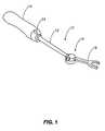
- FIG. 1is a perspective view illustrating one exemplary embodiment of the TLIF inserter device of the present invention, the shaft and inserter piece of the TLIF inserter device in an off-axis initial placement and positioning configuration;
- FIG. 2is another perspective view illustrating the TLIF inserter device of FIG. 1 , the shaft and inserter piece of the TLIF inserter device in an on-axis final impaction and positioning configuration;
- FIG. 3is an exploded perspective view illustrating one exemplary embodiment of the articulating joint mechanism (i.e. slotted capstan and associated locking bar) and associated release mechanism of the TLIF inserter device of FIGS. 1 and 2 ;
- the articulating joint mechanismi.e. slotted capstan and associated locking bar
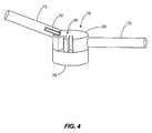
- FIG. 4is a partial perspective view illustrating the articulating joint mechanism (i.e. slotted capstan and associated locking bar) of FIG. 3 in the off-axis initial placement and positioning configuration; and
- FIG. 5is another partial perspective view illustrating the articulating joint mechanism (i.e. slotted capstan and associated locking bar) of FIG. 3 in the on-axis final impaction and positioning configuration.
- articulating joint mechanismi.e. slotted capstan and associated locking bar
- the present inventionrelates generally to devices and methods for performing spinal and other surgical procedures. More specifically, the present invention relates to an articulating TLIF inserter device and an associated method of use.
- This TLIF inserter deviceis configured to relatively simply and easily place and position bone grafts and/or spinal implants in the intervertebral disc spaces of the spine of a patient.
- the TLIF inserter deviceis alternatively substantially curved to minimize tissue disruption and substantially straight to maximize inline impaction forces.
- the TLIF inserter device 10 of the present inventionincludes an elongate shaft 12 having an ergonomic handle 14 on its proximal end and an articulating joint mechanism 16 on its distal end.
- An inserter piece 18 or the likerides on the articulating joint mechanism 16 , and is selectively movable from off-axis with the shaft 12 ( FIG. 1 ) and on-axis with the shaft 12 ( FIG. 2 ).
- the shaft 12is substantially cylindrical and hollow.
- the articulating joint mechanism 16is coupled to and selectively actuated by a release mechanism 24 that is disposed on or adjacent to the handle.
- the articulating joint mechanism 16is coupled to and selectively actuated by the release mechanism 24 via one or more rods, wires, or the like disposed through the shaft 12 .
- the release mechanism 24may actuate the articulating joint mechanism 16 via finger rotation-and-release, finger push-and-release, etc.
- the TLIF inserter device 10is alternatively substantially curved when in an off-axis initial placement and positioning configuration ( FIG. 1 ) to minimize tissue disruption and substantially straight when in an on-axis final impaction and positioning configuration ( FIG. 2 ) to maximize inline impaction forces.
- the force exerted through the TLIF inserter device 10is used to efficiently advance a spinal implant into an intervertebral disc space, by hand and/or with the assistance of an impaction tool.
- the inserter piece 18retains the spinal implant at all relevant times.
- the inserter piece 18is replaced with a threaded connector or the like that is configured to engage the spinal implant, a cutting tool, etc.
- the articulating joint mechanism 16consists of a slotted capstan 20 or the like and corresponding locking bar 22 or the like that are actuated via the release mechanism 24 on or near the handle 14 ( FIG. 1 ) through the one or more rods, wires, or the like 25 disposed through the shaft 12 .
- the release mechanism 24is actuated, causing the locking bar 22 to move either proximally or distally along the shaft 12 , thereby disengaging or engaging one of a plurality of slots 26 associated with the slotted capstan 20 .
- the slotted capstan 20When the locking bar 22 is disengaged from a given slot 26 , the slotted capstan 20 may be pivoted about a retaining pin 28 disposed through a base 29 and advanced to another slot 26 prior to engagement.
- various anglesmay be selected for the inserter piece 18 relative to the shaft 12 .
- three slots 26are provided, corresponding to three inserter piece angles (+/ ⁇ 30-40 degrees off-axis (see FIG. 4 ) and 0 degrees off-axis (see FIG. 5 )), however, more or fewer slots 26 may be provided.
- Other articulating joint mechanisms and release mechanismsmay also be utilized.
- inserter piece 18may also be equipped with an articulation feature, and may consist of other implements. These other implements could include threaded implements, cutting implements, etc., as described above.
Landscapes
- Health & Medical Sciences (AREA)
- Transplantation (AREA)
- Engineering & Computer Science (AREA)
- Biomedical Technology (AREA)
- Orthopedic Medicine & Surgery (AREA)
- Oral & Maxillofacial Surgery (AREA)
- Physical Education & Sports Medicine (AREA)
- Cardiology (AREA)
- Neurology (AREA)
- Heart & Thoracic Surgery (AREA)
- Vascular Medicine (AREA)
- Life Sciences & Earth Sciences (AREA)
- Animal Behavior & Ethology (AREA)
- General Health & Medical Sciences (AREA)
- Public Health (AREA)
- Veterinary Medicine (AREA)
- Prostheses (AREA)
- Surgical Instruments (AREA)
Abstract
Description
Claims (24)
Priority Applications (1)
| Application Number | Priority Date | Filing Date | Title |
|---|---|---|---|
| US12/187,064US8398649B2 (en) | 2007-08-06 | 2008-08-06 | Articulating transforaminal lumbar interbody fusion inserter device and associated method of use |
Applications Claiming Priority (2)
| Application Number | Priority Date | Filing Date | Title |
|---|---|---|---|
| US95413207P | 2007-08-06 | 2007-08-06 | |
| US12/187,064US8398649B2 (en) | 2007-08-06 | 2008-08-06 | Articulating transforaminal lumbar interbody fusion inserter device and associated method of use |
Publications (2)
| Publication Number | Publication Date |
|---|---|
| US20090043312A1 US20090043312A1 (en) | 2009-02-12 |
| US8398649B2true US8398649B2 (en) | 2013-03-19 |
Family
ID=40347235
Family Applications (1)
| Application Number | Title | Priority Date | Filing Date |
|---|---|---|---|
| US12/187,064Expired - Fee RelatedUS8398649B2 (en) | 2007-08-06 | 2008-08-06 | Articulating transforaminal lumbar interbody fusion inserter device and associated method of use |
Country Status (1)
| Country | Link |
|---|---|
| US (1) | US8398649B2 (en) |
Cited By (1)
| Publication number | Priority date | Publication date | Assignee | Title |
|---|---|---|---|---|
| US10478313B1 (en) | 2014-01-10 | 2019-11-19 | Nuvasive, Inc. | Spinal fusion implant and related methods |
Families Citing this family (43)
| Publication number | Priority date | Publication date | Assignee | Title |
|---|---|---|---|---|
| US7985256B2 (en) | 2005-09-26 | 2011-07-26 | Coalign Innovations, Inc. | Selectively expanding spine cage, hydraulically controllable in three dimensions for enhanced spinal fusion |
| US9028550B2 (en) | 2005-09-26 | 2015-05-12 | Coalign Innovations, Inc. | Selectively expanding spine cage with enhanced bone graft infusion |
| US8070813B2 (en) | 2005-09-26 | 2011-12-06 | Coalign Innovations, Inc. | Selectively expanding spine cage, hydraulically controllable in three dimensions for vertebral body replacement |
| US8088163B1 (en) | 2008-02-06 | 2012-01-03 | Kleiner Jeffrey B | Tools and methods for spinal fusion |
| US8932355B2 (en) | 2008-02-22 | 2015-01-13 | Coalign Innovations, Inc. | Spinal implant with expandable fixation |
| US8992620B2 (en) | 2008-12-10 | 2015-03-31 | Coalign Innovations, Inc. | Adjustable distraction cage with linked locking mechanisms |
| US12232975B2 (en) | 2008-02-22 | 2025-02-25 | Howmedica Osteonics Corp. | Lockable spinal implant |
| US8696751B2 (en) | 2008-12-10 | 2014-04-15 | Coalign Innovations, Inc. | Adjustable distraction cage with linked locking mechanisms |
| US20100145455A1 (en)* | 2008-12-10 | 2010-06-10 | Innvotec Surgical, Inc. | Lockable spinal implant |
| US20210378834A1 (en)* | 2008-05-22 | 2021-12-09 | Spinal Surgical Strategies, Inc., A Nevada Corporation D/B/A Kleiner Device Labs | Spinal fusion cage system with inserter |
| USD853560S1 (en) | 2008-10-09 | 2019-07-09 | Nuvasive, Inc. | Spinal implant insertion device |
| US8864654B2 (en) | 2010-04-20 | 2014-10-21 | Jeffrey B. Kleiner | Method and apparatus for performing retro peritoneal dissection |
| US9717403B2 (en) | 2008-12-05 | 2017-08-01 | Jeffrey B. Kleiner | Method and apparatus for performing retro peritoneal dissection |
| US20110144687A1 (en)* | 2009-12-10 | 2011-06-16 | Kleiner Jeffrey | Lateral Based Retractor System |
| US8366748B2 (en) | 2008-12-05 | 2013-02-05 | Kleiner Jeffrey | Apparatus and method of spinal implant and fusion |
| USD656610S1 (en) | 2009-02-06 | 2012-03-27 | Kleiner Jeffrey B | Spinal distraction instrument |
| US9247943B1 (en) | 2009-02-06 | 2016-02-02 | Kleiner Intellectual Property, Llc | Devices and methods for preparing an intervertebral workspace |
| US8998924B2 (en) | 2009-04-16 | 2015-04-07 | Coalign Innovations, Inc. | Insertion handle for surgical implants |
| US8906028B2 (en) | 2009-09-18 | 2014-12-09 | Spinal Surgical Strategies, Llc | Bone graft delivery device and method of using the same |
| US10245159B1 (en) | 2009-09-18 | 2019-04-02 | Spinal Surgical Strategies, Llc | Bone graft delivery system and method for using same |
| USD750249S1 (en) | 2014-10-20 | 2016-02-23 | Spinal Surgical Strategies, Llc | Expandable fusion cage |
| US9173694B2 (en) | 2009-09-18 | 2015-11-03 | Spinal Surgical Strategies, Llc | Fusion cage with combined biological delivery system |
| US9186193B2 (en) | 2009-09-18 | 2015-11-17 | Spinal Surgical Strategies, Llc | Fusion cage with combined biological delivery system |
| US9060877B2 (en) | 2009-09-18 | 2015-06-23 | Spinal Surgical Strategies, Llc | Fusion cage with combined biological delivery system |
| US8685031B2 (en) | 2009-09-18 | 2014-04-01 | Spinal Surgical Strategies, Llc | Bone graft delivery system |
| USD723682S1 (en) | 2013-05-03 | 2015-03-03 | Spinal Surgical Strategies, Llc | Bone graft delivery tool |
| US20170238984A1 (en) | 2009-09-18 | 2017-08-24 | Spinal Surgical Strategies, Llc | Bone graft delivery device with positioning handle |
| US9629729B2 (en) | 2009-09-18 | 2017-04-25 | Spinal Surgical Strategies, Llc | Biological delivery system with adaptable fusion cage interface |
| US10973656B2 (en) | 2009-09-18 | 2021-04-13 | Spinal Surgical Strategies, Inc. | Bone graft delivery system and method for using same |
| US20110093014A1 (en)* | 2009-10-19 | 2011-04-21 | Zimmer Spine, Inc. | Rod with Removable End and Inserter Therefor |
| US8870880B2 (en)* | 2010-04-12 | 2014-10-28 | Globus Medical, Inc. | Angling inserter tool for expandable vertebral implant |
| US8956414B2 (en) | 2010-04-21 | 2015-02-17 | Spinecraft, LLC | Intervertebral body implant, instrument and method |
| USD736377S1 (en)* | 2012-09-13 | 2015-08-11 | Hpf Spa | Milling tool for prosthetic surgery operations |
| USD736376S1 (en)* | 2012-09-13 | 2015-08-11 | Hpf Spa | Milling tool for prosthetic surgery operations |
| USD797290S1 (en) | 2015-10-19 | 2017-09-12 | Spinal Surgical Strategies, Llc | Bone graft delivery tool |
| US10548738B2 (en) | 2016-04-07 | 2020-02-04 | Howmedica Osteonics Corp. | Expandable interbody implant |
| US10285825B2 (en) | 2016-04-07 | 2019-05-14 | Howmedica Osteonics Corp. | Surgical insertion instruments |
| AU2017203369B2 (en) | 2016-05-20 | 2022-04-28 | Vb Spine Us Opco Llc | Expandable interbody implant with lordosis correction |
| AU2017228529B2 (en) | 2016-09-12 | 2022-03-10 | Vb Spine Us Opco Llc | Interbody implant with independent control of expansion at multiple locations |
| AU2017251734B2 (en) | 2016-10-26 | 2022-10-20 | Vb Spine Us Opco Llc | Expandable interbody implant with lateral articulation |
| EP3456297B1 (en) | 2017-09-15 | 2023-10-04 | Howmedica Osteonics Corp. | Instruments for expandable interbody implants |
| EP3456294B1 (en) | 2017-09-15 | 2024-06-05 | Stryker European Operations Holdings LLC | Intervertebral body fusion device expanded with hardening material |
| CN118042995A (en)* | 2021-09-22 | 2024-05-14 | 脊柱外科策略有限公司 | Surgical instrument |
Citations (12)
| Publication number | Priority date | Publication date | Assignee | Title |
|---|---|---|---|---|
| US20040153065A1 (en)* | 2003-02-03 | 2004-08-05 | Lim Roy K. | Expanding interbody implant and articulating inserter and method |
| US20050096745A1 (en)* | 2003-10-29 | 2005-05-05 | Eurosurgical Sa | Intersomatic cage for lumbar fusion by transforaminal approach and its cage carrying device |
| US20060229627A1 (en)* | 2004-10-29 | 2006-10-12 | Hunt Margaret M | Variable angle spinal surgery instrument |
| US20060235426A1 (en)* | 2005-04-15 | 2006-10-19 | Sdgi Holdings, Inc. | Instruments, implants and methods for positioning implants into a spinal disc space |
| US20060241761A1 (en)* | 2005-04-08 | 2006-10-26 | G&L Consulting | Spine implant insertion device and method |
| US20070225726A1 (en)* | 2006-03-23 | 2007-09-27 | Justin Dye | Instruments for delivering spinal implants |
| US20070225808A1 (en)* | 2006-03-22 | 2007-09-27 | Warnick David R | Pivotable interbody spacer |
| US20080009880A1 (en)* | 2006-03-22 | 2008-01-10 | Warnick David R | Pivotable Vetrebral Spacer |
| US20080077153A1 (en)* | 2006-09-22 | 2008-03-27 | Pioneer Surgical Technology, Inc. | System and methods for inserting a spinal disc device into an intervertebral space |
| US7470273B2 (en)* | 2004-06-25 | 2008-12-30 | Ebi, Llc | Tool for intervertebral implant manipulation |
| US7901458B2 (en)* | 2005-12-16 | 2011-03-08 | Warsaw Orthopedic, Inc. | Intervertebral spacer and insertion tool |
| US7988695B2 (en)* | 2005-12-21 | 2011-08-02 | Theken Spine, Llc | Articulated delivery instrument |
- 2008
- 2008-08-06USUS12/187,064patent/US8398649B2/ennot_activeExpired - Fee Related
Patent Citations (13)
| Publication number | Priority date | Publication date | Assignee | Title |
|---|---|---|---|---|
| US20040153065A1 (en)* | 2003-02-03 | 2004-08-05 | Lim Roy K. | Expanding interbody implant and articulating inserter and method |
| US20050096745A1 (en)* | 2003-10-29 | 2005-05-05 | Eurosurgical Sa | Intersomatic cage for lumbar fusion by transforaminal approach and its cage carrying device |
| US7470273B2 (en)* | 2004-06-25 | 2008-12-30 | Ebi, Llc | Tool for intervertebral implant manipulation |
| US20060229627A1 (en)* | 2004-10-29 | 2006-10-12 | Hunt Margaret M | Variable angle spinal surgery instrument |
| US20060241761A1 (en)* | 2005-04-08 | 2006-10-26 | G&L Consulting | Spine implant insertion device and method |
| US20060235426A1 (en)* | 2005-04-15 | 2006-10-19 | Sdgi Holdings, Inc. | Instruments, implants and methods for positioning implants into a spinal disc space |
| US7901458B2 (en)* | 2005-12-16 | 2011-03-08 | Warsaw Orthopedic, Inc. | Intervertebral spacer and insertion tool |
| US7988695B2 (en)* | 2005-12-21 | 2011-08-02 | Theken Spine, Llc | Articulated delivery instrument |
| US20070225808A1 (en)* | 2006-03-22 | 2007-09-27 | Warnick David R | Pivotable interbody spacer |
| US20080009880A1 (en)* | 2006-03-22 | 2008-01-10 | Warnick David R | Pivotable Vetrebral Spacer |
| US20070225726A1 (en)* | 2006-03-23 | 2007-09-27 | Justin Dye | Instruments for delivering spinal implants |
| US7976549B2 (en)* | 2006-03-23 | 2011-07-12 | Theken Spine, Llc | Instruments for delivering spinal implants |
| US20080077153A1 (en)* | 2006-09-22 | 2008-03-27 | Pioneer Surgical Technology, Inc. | System and methods for inserting a spinal disc device into an intervertebral space |
Cited By (1)
| Publication number | Priority date | Publication date | Assignee | Title |
|---|---|---|---|---|
| US10478313B1 (en) | 2014-01-10 | 2019-11-19 | Nuvasive, Inc. | Spinal fusion implant and related methods |
Also Published As
| Publication number | Publication date |
|---|---|
| US20090043312A1 (en) | 2009-02-12 |
Similar Documents
| Publication | Publication Date | Title |
|---|---|---|
| US8398649B2 (en) | Articulating transforaminal lumbar interbody fusion inserter device and associated method of use | |
| US11723697B2 (en) | Patient-mounted surgical support | |
| US11918486B2 (en) | Devices and methods for minimally invasive spinal stabilization and instrumentation | |
| US12349945B2 (en) | Patient-mounted surgical support | |
| JP4889724B2 (en) | Spinal system and method including lateral approach | |
| US8795167B2 (en) | Spinal therapy lateral approach access instruments | |
| US11369490B2 (en) | Universal trial for lateral cages | |
| US7655012B2 (en) | Methods and apparatuses for minimally invasive replacement of intervertebral discs | |
| US7645232B2 (en) | Access device for minimally invasive surgery | |
| EP2568897B1 (en) | Bone fixation rod and implantation device for insertion thereof | |
| US20220110765A1 (en) | Devices and methods for spinal implantation | |
| US20080306557A1 (en) | Inserter for a spinal implant | |
| US20060217807A1 (en) | Spinal device including lateral approach | |
| JP2007521886A (en) | System and method for spinal surgery | |
| JP2005503859A (en) | Method and apparatus for inserting and manipulating surgical instruments | |
| US11779470B2 (en) | Devices for inserting and expanding spinal implants | |
| US12263098B2 (en) | Intervertebral prosthetic disc placement and removal systems | |
| JP2024521336A (en) | Medical instrument set, medical device, medical method | |
| US20200237358A1 (en) | Multilevel lateral access system | |
| WO2023196246A1 (en) | Steerable and expandable interbody fusion device and associated instrumentation | |
| US20240041504A1 (en) | Restoring spinal alignment and/or range of motion using bilateral implants | |
| US20240009002A1 (en) | Methods for restoring bilateral spinal alignment and/or range of motion | |
| US20240041616A1 (en) | Restoring spinal alignment and/or range of motion |
Legal Events
| Date | Code | Title | Description |
|---|---|---|---|
| AS | Assignment | Owner name:U.S. SPINAL TECHNOLOGIES, L.L.C., FLORIDA Free format text:ASSIGNMENT OF ASSIGNORS INTEREST;ASSIGNORS:KOULISIS, CHRISTO;CROOK, DAVID;REEL/FRAME:021632/0090;SIGNING DATES FROM 20080927 TO 20080929 Owner name:U.S. SPINAL TECHNOLOGIES, L.L.C., FLORIDA Free format text:ASSIGNMENT OF ASSIGNORS INTEREST;ASSIGNORS:KOULISIS, CHRISTO;CROOK, DAVID;SIGNING DATES FROM 20080927 TO 20080929;REEL/FRAME:021632/0090 | |
| AS | Assignment | Owner name:US SPINE, INC., UTAH Free format text:CHANGE OF NAME;ASSIGNOR:U.S. SPINAL TECHNOLOGIES, LLC;REEL/FRAME:025420/0972 Effective date:20101123 | |
| AS | Assignment | Owner name:ZIONS FIRST NATIONAL BANK, UTAH Free format text:SECURITY AGREEMENT;ASSIGNOR:US SPINE, INC.;REEL/FRAME:025434/0317 Effective date:20100917 | |
| AS | Assignment | Owner name:KARL KIPKE, AS COLLATERAL AGENT, TEXAS Free format text:SECURITY AGREEMENT;ASSIGNOR:AMEDICA CORPORATION;REEL/FRAME:025900/0168 Effective date:20110303 | |
| AS | Assignment | Owner name:US SPINE, INC., UTAH Free format text:RELEASE BY SECURED PARTY;ASSIGNOR:ZIONS FIRST NATIONAL BANK;REEL/FRAME:029491/0085 Effective date:20121217 Owner name:GE CAPITAL EQUITY INVESTMENTS, INC. C/O GE HEALTHC Free format text:SECURITY AGREEMENT;ASSIGNORS:AMEDICA CORPORATION;US SPINE, INC.;REEL/FRAME:029495/0211 Effective date:20121214 Owner name:AMEDICA CORPORATION, UTAH Free format text:RELEASE BY SECURED PARTY;ASSIGNOR:AS COLLATERAL AGENT, KARL KIPKE;REEL/FRAME:029492/0321 Effective date:20121214 | |
| STCF | Information on status: patent grant | Free format text:PATENTED CASE | |
| AS | Assignment | Owner name:GENERAL ELECTRIC CAPITAL CORPORATION, MARYLAND Free format text:CORRECTIVE ASSIGNMENT TO CORRECT THE NAME OF THE ASSIGNEE PREVIOUSLY RECORDED ON REEL 029495 FRAME 0211. ASSIGNOR(S) HEREBY CONFIRMS THE ASSIGNOR: AMEDICA CORPORATION ASSIGNOR: US SPINE, INC. ASSIGNEE: GENERAL ELECTRIC CAPITAL CORPORATION;ASSIGNORS:AMEDICA CORPORATION;US SPINE, INC.;REEL/FRAME:031581/0831 Effective date:20121214 | |
| FPAY | Fee payment | Year of fee payment:4 | |
| AS | Assignment | Owner name:AMEDICA CORPORATION, UTAH Free format text:ASSIGNMENT OF ASSIGNORS INTEREST;ASSIGNOR:U.S. SPINE, INC.;REEL/FRAME:044795/0780 Effective date:20180127 | |
| AS | Assignment | Owner name:AMEDICA CORPORATION, UTAH Free format text:RELEASE BY SECURED PARTY;ASSIGNOR:GENERAL ELECTRIC CAPITAL CORPORATION;REEL/FRAME:047199/0313 Effective date:20140630 Owner name:US SPINE, INC., UTAH Free format text:RELEASE BY SECURED PARTY;ASSIGNOR:GENERAL ELECTRIC CAPITAL CORPORATION;REEL/FRAME:047199/0313 Effective date:20140630 | |
| AS | Assignment | Owner name:US SPINE, INC., UTAH Free format text:CORRECTIVE ASSIGNMENT TO CORRECT THE PATENT NUMBER PREVIOUSLY RECORDED AT REEL: 047199 FRAME: 0313. ASSIGNOR(S) HEREBY CONFIRMS THE RELEASE OF SECURITY INTEREST;ASSIGNOR:GENERAL ELECTRIC CAPITAL CORPORATION;REEL/FRAME:047403/0953 Effective date:20140630 Owner name:AMEDICA CORPORATION, UTAH Free format text:CORRECTIVE ASSIGNMENT TO CORRECT THE PATENT NUMBER PREVIOUSLY RECORDED AT REEL: 047199 FRAME: 0313. ASSIGNOR(S) HEREBY CONFIRMS THE RELEASE OF SECURITY INTEREST;ASSIGNOR:GENERAL ELECTRIC CAPITAL CORPORATION;REEL/FRAME:047403/0953 Effective date:20140630 | |
| AS | Assignment | Owner name:CTL MEDICAL CORPORATION, TEXAS Free format text:ASSIGNMENT OF ASSIGNORS INTEREST;ASSIGNORS:AMEDICA CORPORATION;U.S. SPINE, INC.;REEL/FRAME:051368/0261 Effective date:20181001 | |
| FEPP | Fee payment procedure | Free format text:MAINTENANCE FEE REMINDER MAILED (ORIGINAL EVENT CODE: REM.); ENTITY STATUS OF PATENT OWNER: SMALL ENTITY | |
| LAPS | Lapse for failure to pay maintenance fees | Free format text:PATENT EXPIRED FOR FAILURE TO PAY MAINTENANCE FEES (ORIGINAL EVENT CODE: EXP.); ENTITY STATUS OF PATENT OWNER: SMALL ENTITY | |
| STCH | Information on status: patent discontinuation | Free format text:PATENT EXPIRED DUE TO NONPAYMENT OF MAINTENANCE FEES UNDER 37 CFR 1.362 | |
| FP | Lapsed due to failure to pay maintenance fee | Effective date:20210319 |