US8398619B2 - Flexible wrist-type element and methods of manufacture and use thereof - Google Patents
Flexible wrist-type element and methods of manufacture and use thereofDownload PDFInfo
- Publication number
- US8398619B2 US8398619B2US12/493,967US49396709AUS8398619B2US 8398619 B2US8398619 B2US 8398619B2US 49396709 AUS49396709 AUS 49396709AUS 8398619 B2US8398619 B2US 8398619B2
- Authority
- US
- United States
- Prior art keywords
- couplings
- hub
- body housing
- guide
- type element
- Prior art date
- Legal status (The legal status is an assumption and is not a legal conclusion. Google has not performed a legal analysis and makes no representation as to the accuracy of the status listed.)
- Active, expires
Links
- 238000000034methodMethods0.000titleabstractdescription8
- 238000004519manufacturing processMethods0.000titledescription5
- 230000008878couplingEffects0.000claimsabstractdescription139
- 238000010168coupling processMethods0.000claimsabstractdescription139
- 238000005859coupling reactionMethods0.000claimsabstractdescription139
- 239000012636effectorSubstances0.000claimsabstractdescription68
- 230000007246mechanismEffects0.000claimsabstractdescription61
- 230000033001locomotionEffects0.000claimsdescription65
- 230000004044responseEffects0.000claimsdescription10
- 238000004891communicationMethods0.000claimsdescription5
- 230000006835compressionEffects0.000claimsdescription3
- 238000007906compressionMethods0.000claimsdescription3
- 239000012811non-conductive materialSubstances0.000claimsdescription3
- 230000003993interactionEffects0.000claimsdescription2
- 230000005540biological transmissionEffects0.000description5
- 230000000694effectsEffects0.000description3
- 239000000314lubricantSubstances0.000description3
- 125000006850spacer groupChemical group0.000description3
- 238000012546transferMethods0.000description3
- 238000005452bendingMethods0.000description2
- 239000012530fluidSubstances0.000description2
- 238000012084abdominal surgeryMethods0.000description1
- 230000009471actionEffects0.000description1
- 230000000712assemblyEffects0.000description1
- 238000000429assemblyMethods0.000description1
- 230000004323axial lengthEffects0.000description1
- 239000011248coating agentSubstances0.000description1
- 238000000576coating methodMethods0.000description1
- 239000004020conductorSubstances0.000description1
- 238000005520cutting processMethods0.000description1
- 238000009826distributionMethods0.000description1
- 238000005516engineering processMethods0.000description1
- 230000006870functionEffects0.000description1
- 230000001050lubricating effectEffects0.000description1
- 238000012986modificationMethods0.000description1
- 230000004048modificationEffects0.000description1
- 239000000126substanceSubstances0.000description1
Images


Classifications
- B—PERFORMING OPERATIONS; TRANSPORTING
- B25—HAND TOOLS; PORTABLE POWER-DRIVEN TOOLS; MANIPULATORS
- B25J—MANIPULATORS; CHAMBERS PROVIDED WITH MANIPULATION DEVICES
- B25J17/00—Joints
- B25J17/02—Wrist joints
- A—HUMAN NECESSITIES
- A61—MEDICAL OR VETERINARY SCIENCE; HYGIENE
- A61B—DIAGNOSIS; SURGERY; IDENTIFICATION
- A61B34/00—Computer-aided surgery; Manipulators or robots specially adapted for use in surgery
- A61B34/70—Manipulators specially adapted for use in surgery
- B—PERFORMING OPERATIONS; TRANSPORTING
- B25—HAND TOOLS; PORTABLE POWER-DRIVEN TOOLS; MANIPULATORS
- B25J—MANIPULATORS; CHAMBERS PROVIDED WITH MANIPULATION DEVICES
- B25J9/00—Programme-controlled manipulators
- B25J9/06—Programme-controlled manipulators characterised by multi-articulated arms
- F—MECHANICAL ENGINEERING; LIGHTING; HEATING; WEAPONS; BLASTING
- F16—ENGINEERING ELEMENTS AND UNITS; GENERAL MEASURES FOR PRODUCING AND MAINTAINING EFFECTIVE FUNCTIONING OF MACHINES OR INSTALLATIONS; THERMAL INSULATION IN GENERAL
- F16C—SHAFTS; FLEXIBLE SHAFTS; ELEMENTS OR CRANKSHAFT MECHANISMS; ROTARY BODIES OTHER THAN GEARING ELEMENTS; BEARINGS
- F16C11/00—Pivots; Pivotal connections
- A—HUMAN NECESSITIES
- A61—MEDICAL OR VETERINARY SCIENCE; HYGIENE
- A61B—DIAGNOSIS; SURGERY; IDENTIFICATION
- A61B18/00—Surgical instruments, devices or methods for transferring non-mechanical forms of energy to or from the body
- A61B18/04—Surgical instruments, devices or methods for transferring non-mechanical forms of energy to or from the body by heating
- A61B18/12—Surgical instruments, devices or methods for transferring non-mechanical forms of energy to or from the body by heating by passing a current through the tissue to be heated, e.g. high-frequency current
- A61B18/14—Probes or electrodes therefor
- A61B18/1442—Probes having pivoting end effectors, e.g. forceps
- A61B18/1445—Probes having pivoting end effectors, e.g. forceps at the distal end of a shaft, e.g. forceps or scissors at the end of a rigid rod
- A—HUMAN NECESSITIES
- A61—MEDICAL OR VETERINARY SCIENCE; HYGIENE
- A61B—DIAGNOSIS; SURGERY; IDENTIFICATION
- A61B17/00—Surgical instruments, devices or methods
- A61B2017/00535—Surgical instruments, devices or methods pneumatically or hydraulically operated
- A61B2017/00539—Surgical instruments, devices or methods pneumatically or hydraulically operated hydraulically
- A—HUMAN NECESSITIES
- A61—MEDICAL OR VETERINARY SCIENCE; HYGIENE
- A61B—DIAGNOSIS; SURGERY; IDENTIFICATION
- A61B17/00—Surgical instruments, devices or methods
- A61B2017/00535—Surgical instruments, devices or methods pneumatically or hydraulically operated
- A61B2017/00544—Surgical instruments, devices or methods pneumatically or hydraulically operated pneumatically
- A—HUMAN NECESSITIES
- A61—MEDICAL OR VETERINARY SCIENCE; HYGIENE
- A61B—DIAGNOSIS; SURGERY; IDENTIFICATION
- A61B17/00—Surgical instruments, devices or methods
- A61B17/28—Surgical forceps
- A61B17/29—Forceps for use in minimally invasive surgery
- A61B2017/2926—Details of heads or jaws
- A61B2017/2932—Transmission of forces to jaw members
- A61B2017/2933—Transmission of forces to jaw members camming or guiding means
- A61B2017/2936—Pins in guiding slots
- Y—GENERAL TAGGING OF NEW TECHNOLOGICAL DEVELOPMENTS; GENERAL TAGGING OF CROSS-SECTIONAL TECHNOLOGIES SPANNING OVER SEVERAL SECTIONS OF THE IPC; TECHNICAL SUBJECTS COVERED BY FORMER USPC CROSS-REFERENCE ART COLLECTIONS [XRACs] AND DIGESTS
- Y10—TECHNICAL SUBJECTS COVERED BY FORMER USPC
- Y10T—TECHNICAL SUBJECTS COVERED BY FORMER US CLASSIFICATION
- Y10T74/00—Machine element or mechanism
- Y10T74/20—Control lever and linkage systems
- Y10T74/20207—Multiple controlling elements for single controlled element
- Y10T74/20305—Robotic arm
- Y10T74/20317—Robotic arm including electric motor
- Y—GENERAL TAGGING OF NEW TECHNOLOGICAL DEVELOPMENTS; GENERAL TAGGING OF CROSS-SECTIONAL TECHNOLOGIES SPANNING OVER SEVERAL SECTIONS OF THE IPC; TECHNICAL SUBJECTS COVERED BY FORMER USPC CROSS-REFERENCE ART COLLECTIONS [XRACs] AND DIGESTS
- Y10—TECHNICAL SUBJECTS COVERED BY FORMER USPC
- Y10T—TECHNICAL SUBJECTS COVERED BY FORMER US CLASSIFICATION
- Y10T74/00—Machine element or mechanism
- Y10T74/20—Control lever and linkage systems
- Y10T74/20207—Multiple controlling elements for single controlled element
- Y10T74/20305—Robotic arm
- Y10T74/20329—Joint between elements
- Y10T74/20335—Wrist
Definitions
- aspects of the present inventionrelate to a flexible wrist-type element and methods of manufacture and use thereof, including variations having an angularly moveable hub housing and a rotatable and operable end effector driven via a drive train having one or more flexible couplings, such as universal-type joints.
- the described aspectsrelate to flexible wrist-type elements capable of transmitting axial and/or rotational force around corners and bends.
- these aspectsare discussed herein with respect to a surgical application, however, it should be understood that these aspect may equally apply to many other applications, such as robotics, manufacturing, remote controlled operations, etc., and any application where the transmission of axial and/or rotational force around corners and bends is desired.
- aspects of the present inventioninclude features relating to a flexible wrist-type element for surgical-related activities and methods of manufacture and use thereof, including variations having an angularly moveable hub housing and a rotatable and operable end effector driven via additional drive train elements that include one or more flexible couplings, such as universal-type joints.
- Force transmitted via the set of such elementsincludes, for example, lineal force and rotational force.
- aspects of the present inventioninclude a push-pull-rotate (PPR) element that permits the transmission of axial forces and angular torques around corners or bends.
- the PPR elementmay include one or more universal joints (e.g., Hooke's joints) or similarly operating mechanisms arranged in series (in a chain-like configuration) and connected to an input and to an output.
- the PPR elementmay be contained within a housing.
- a guide elementis provided to prevent portions of the PPR element from collapsing under compression and to maintain proper form under extension, among other things.
- Exemplary motion that may be transmitted to the end effector and/or tools via the PPR elementmay include rotational motion and push-pull or reciprocating motion that may be used, for example, to cause two or more extensions of the end effector to move relative to one another (e.g., to open and close to allow grasping or cutting, and release).
- the guide elementis responsive to the bend angle and is adjusted appropriately or automatically adjusts its position as a function of operation of the device within a motion limiting mechanism, such as a guide track into which an extension from the guide element slides.
- the bending of the device to various bend anglesmay be accomplished via use of one or more pivot points and control mechanisms, such as tendon-like linkages.
- the PPR elementmay be attached to a source or sources of axial and torsional input (also interchangeably referred to herein as an “input mechanism”), such as a rotatable and extendable and retractable shaft, housed in a body portion.
- Axial and torsional inputs to each of the PPR elementsare then transmitted from the PPR elements to any output, such as to permit rotation and operation of an end effector.
- the end effectormay rotate, for example, relative to the PPR element via a sleeve.
- Some variations of the present inventionuse one or more essentially friction-free or low friction components in the PPR element and guide system, such as rolling-element bearings, which results in relatively high mechanical efficiencies (e.g., as compared to push-pull cables or cable-pulley systems).
- Other portions of the system relating to movementsuch as guide track pins and pivots in some variations, can optionally be replaced with or further include low-friction rolling-element bearings for even smoother action.
- Appropriate guide track, guide housing, and hub or rotating tip componentscan comprise non-conductive material to manage the distribution of electrical energy to end-effectors. Any components may be plated with an appropriate anti-friction and/or electrically insulating coating and/or be used with suitable lubricating substance or features.
- some portions of the systemmay be electrically conductive, such as for use in electrosurgery applications.
- the outer housing of the devicemay be non-conductive, so as to insulate inner conductive portions.
- the motion transmitting inner portionsmay be conductive so as to allow electrosurgical current to be delivered to the end effector and/or any tools used therewith, while the outer housing thereby insulates the device.
- conducting lubricantsmay also be used to ensure or enhance electrical communication.
- the electrical energy communicatedmay be of high frequency to enhance communication of the energy across abutting surfaces and lubricants.
- a flexible wrist-type elementcomprises a body housing extending along a first longitudinal axis, a hub and a plurality of couplings.
- the hubat least partially extends along a second longitudinal axis and is movably connected to the body housing.
- the hubcomprises a first end movable to a first position defining a first angle between the second longitudinal axis and the first longitudinal axis of the body housing, wherein the first angle is variable.
- the plurality of couplingscomprise a plurality of elements movably interconnected by a plurality of joints, wherein the plurality of couplings are movably positionable relative to the body housing and the hub.
- the plurality of couplingshave an input end adjacent to the body housing and an opposing output end adjacent to the first end of the hub, wherein the input end is configured to receive an input force comprising at least one of an axial force or a torsional force. Additionally, the plurality of couplings are configured to transmit at least a portion of the input force from the input end to the output end when the first end of the hub is in the first position defining the first angle.
- the body housingcomprises an extension adjacent to the hub, wherein the extension comprises an inner wall defining a surface, wherein the plurality of couplings are in movable contact with the surface, wherein the surface defines limits for movement of the plurality of couplings relative to the body housing and the hub.
- the extensionmay extend along a third longitudinal axis, and wherein the surface defines a slot having a first length substantially parallel to the third longitudinal axis and a second length substantially perpendicular to the third longitudinal axis, wherein the first length is greater than the second length.
- the flexible wrist-type element described abovemay further comprise a guide element movably connected to the body housing and the hub, wherein the guide element is further movably connected to the plurality of couplings and further comprises a surface, where the surface defines limits for movement of the plurality of couplings.
- the guide elementmay be movable to a second angle relative to the body housing when the first end of the hub is in the first position defining the first angle relative to the body housing, wherein the second angle is less than the first angle.
- the guide elementmay further comprise opposing ends, wherein the first guide end is rotatably connected to a first one of the body housing or the hub adjacent to a first one of the opposing ends, and wherein the guide element is slidably connected to a second one of the body housing or the hub adjacent to a second one of the opposing ends.
- the flexible wrist-type element described abovemay further comprise a guide housing movably connected to the body housing and the hub, wherein the guide housing is further movably connected to at least one of the plurality of couplings and comprises a support surface supporting the at least one of the plurality of couplings during movement of the first end of the hub to the first position defining the first angle.
- the support surfacemay limit an amount of pivoting between the plurality of couplings.
- the support surfacemay prevent portions of the plurality of couplings from collapsing under compression and maintains alignment of the plurality of couplings under extension.
- the body housingmay comprise an extension adjacent to the hub, wherein the extension comprises an inner wall defining a first slot, wherein the guide housing further comprises a support element, and further comprising a guide element having a first guide end, a second guide end and a second slot, wherein the first guide end is movably connected to the body housing within the first slot, wherein the second guide end is movably connected to the hub, and wherein the support element of the guide housing is movably connected within the second slot of the guide element such that the second slot defines a limit for movement of the plurality of couplings.
- the first slotmay define an angular limit of the first angle
- the second slotdefines an axial limit of movement of the plurality of couplings in response to the input force comprising the axial force.
- the guide housingis connected to the at least one of the plurality of couplings at one of the plurality of joints.
- the flexible wrist-type elementmay further comprise a bearing element positioned between the support surface and the at least one of the plurality of couplings, wherein the bearing element allows the at least one of the plurality of couplings to rotate relative to the guide housing.
- each of the plurality of jointscomprises a universal joint or a Hooke's joint.
- each of the plurality of jointscomprises a first pair of ball bearings, spaced apart along a first axis, supporting a first one of the plurality of elements and a second pair of ball bearings, spaced apart along a second axis, supporting a second one of the plurality of elements, wherein the first axis is substantially perpendicular to the second axis.
- each of the plurality of jointscomprises a constant-velocity joint.
- each of the plurality of elementscomprises a first rigid end having a first engagement surface and a second rigid end having a second engagement surface, wherein each of the plurality of joints is defined by a movable interaction between the first engagement surface of a respective first element and the second engagement surface of a respective second element, wherein one of the first engagement surface and the second engagement surface comprises a curved surface.
- each of the plurality of elementsfurther comprises a shaft portion connecting the first rigid end and the second rigid end, further comprising a guide housing having an extending support element and a connection with the shaft that allows relative rotation and prevents relative axial movement, and further comprising a guide element movably connected to the body housing and the hub, wherein the guide element comprises a surface movably connected to the support element of the guide housing, wherein the surface defines limits for movement of the plurality of couplings.
- the plurality of jointscomprise at least three joints.
- the flexible wrist-type element described abovemay further comprise a drive system having an input mechanism coupled to the input end of the plurality of couplings, wherein the drive system generates the input force.
- the drive systemfurther generates another force to move the first end of the hub to the first position defining the first angle.
- the drive systemfurther comprises at least one of an electric system, a hydraulic system, a magnetic system, or a mechanical system.
- the flexible wrist-type element described abovemay further comprise a drive system having an input mechanism coupled to the input end of the plurality of couplings, wherein the drive system comprises a manually-driven hydraulic system.
- the flexible wrist-type element described abovemay further comprise an end effector coupled to the output end of the plurality of couplings, wherein the end effector moves in response to receiving at least the portion of the input force transmitted by the plurality of couplings.
- the end effectorcomprises a surgical tool.
- the flexible wrist-type element described abovemay further comprise a manually-driven hydraulic drive system having an input mechanism coupled to the input end of the plurality of couplings, wherein the drive system generates the input force, and an end effector coupled to the output end of the plurality of couplings, wherein the end effector comprises a surgical tool and moves in response to receiving at least the portion of the input force transmitted by the plurality of couplings.
- a manually-driven hydraulic drive systemhaving an input mechanism coupled to the input end of the plurality of couplings, wherein the drive system generates the input force, and an end effector coupled to the output end of the plurality of couplings, wherein the end effector comprises a surgical tool and moves in response to receiving at least the portion of the input force transmitted by the plurality of couplings.
- At least one of the body housing and the hubcomprise an electrically non-conductive material, and further comprising an end effector connected to the hub and in communication with an electrically conductive portion within the body housing and the hub, wherein the end effector is configured to receive an electrical current delivered via the electrically conductive portion.
- a flexible wrist-type elementcomprises a body housing extending along a first longitudinal axis, a hub, a plurality of couplings, a guide element, and a guide housing.
- the hubat least partially extends along a second longitudinal axis and is movably connected to the body housing, wherein the hub comprises a first end movable to a first position defining a first angle between the second longitudinal axis and the first longitudinal axis of the body housing, wherein the first angle is greater than zero degrees.
- the a plurality of couplingscomprise a plurality of elements movably interconnected by a plurality of joints, wherein the plurality of couplings are movably positionable relative to the body housing and the hub.
- the plurality of couplingshave an input end adjacent to the body housing and an opposing output end adjacent to the first end of the hub, wherein the input end is configured to receive an input force comprising at least one of an axial force or a torsional force. Additionally, the plurality of couplings are configured to transmit at least a portion of the input force from the input end to the output end when the first end of the hub is in the first position defining the first angle. Also, the guide element is movably connected to the body housing, the hub and the plurality of couplings, wherein the guide element further comprises a surface that defines limits for movement of the plurality of couplings.
- the guide elementis movable to a second angle relative to the body housing when the first end of the hub is in the first position defining the first angle relative to the body housing, wherein the second angle is less than the first angle.
- the guide housingis connected to the body housing and the hub via a movable connection with the guide element, wherein the guide housing is further movably connected to at least one of the plurality of couplings and comprises a support surface supporting the at least one of the plurality of couplings during movement of the first end of the hub to the first position defining the first angle.
- the flexible wrist-type elementmay further comprise a manually-driven hydraulic drive system having an input mechanism coupled to the input end of the plurality of couplings, wherein the drive system generates the input force, and an end effector coupled to the output end of the plurality of couplings, wherein the end effector comprises a surgical tool and moves in response to receiving at least the portion of the input force transmitted by the plurality of couplings.
- a manually-driven hydraulic drive systemhaving an input mechanism coupled to the input end of the plurality of couplings, wherein the drive system generates the input force, and an end effector coupled to the output end of the plurality of couplings, wherein the end effector comprises a surgical tool and moves in response to receiving at least the portion of the input force transmitted by the plurality of couplings.
- a flexible wrist-type elementcomprises a body housing extending along a first longitudinal axis, a hub, a plurality of couplings, a guide element, a guide housing, a drive system, and an end effector.
- the hubat least partially extends along a second longitudinal axis and is movably connected to the body housing, wherein the hub comprises a first end movable to a first position defining a first angle between the second longitudinal axis and the first longitudinal axis of the body housing, wherein the first angle is greater than zero degrees.
- the plurality of couplingscomprise a plurality of elements movably interconnected by a plurality of joints, wherein the plurality of couplings are movably positionable relative to the body housing and the hub.
- the plurality of couplingshave an input end adjacent to the body housing and an opposing output end adjacent to the first end of the hub, wherein the input end is configured to receive an input force comprising at least one of an axial force or a torsional force, and wherein the plurality of couplings are configured to transmit at least a portion of the input force from the input end to the output end when the first end of the hub is in the first position defining the first angle.
- the guide elementis movably connected to the body housing, the hub and the plurality of couplings, wherein the guide element further comprises a surface that defines limits for movement of the plurality of couplings, wherein the guide element is movable to a second angle relative to the body housing when the first end of the hub is in the first position defining the first angle relative to the body housing, wherein the second angle is less than the first angle.
- the guide housingis connected to the body housing and the hub via a movable connection with the guide element, and the guide housing is further movably connected to at least one of the plurality of couplings and comprises a support surface supporting the at least one of the plurality of couplings during movement of the first end of the hub to the first position defining the first angle.
- the drive systemhas an input mechanism coupled to the input end of the plurality of couplings, wherein the drive system generates the input force.
- the end effectoris coupled to the output end of the plurality of couplings, wherein the end effector moves in response to receiving at least the portion of the input force transmitted by the plurality of couplings.
- the drive systemcomprises a manually-driven hydraulic system, and wherein the end effector comprises a surgical tool.
- FIG. 1shows a view of an exemplary flexible wrist-type element, in accordance with aspects of the present invention
- FIG. 2shows the flexible wrist-type element of FIG. 1 , with the end effector portion rotated and in an open position, relative to the position of FIG. 1 ;
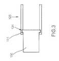
- FIG. 3shows a partial cutaway view of various elements of an exemplary hub and end effector sleeve enabling relative rotation therebetween, in accordance with aspects of the present invention
- FIG. 4shows the flexible wrist-type element of FIG. 1 oriented such that the hub portion is angled relative to the body portion;
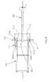
- FIG. 5presents a partial cutaway view of one exemplary flexible wrist-type element, in accordance with aspects of the present invention, in a similar position to that shown in FIG. 1 ;
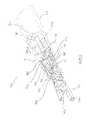
- FIG. 6shows a partial cutaway view of various elements of exemplary flexible couplings and a guide housing, in accordance with aspects of the present invention
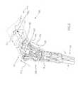
- FIG. 7presents a partial cutaway view of an exemplary flexible wrist-type element, in accordance with aspects of the present invention, in a similar position to that shown in FIG. 4 ;
- FIG. 8contains a partial cutaway view of an exemplary flexible wrist-type element, in accordance with aspects of the present invention, having the angled position of the hub relative to the body portion in a similar orientation to that shown in FIG. 4 , with the end effector in an open and first rotated position relative to that of FIG. 7 ;
- FIG. 9shows a partial cutaway view of an exemplary flexible wrist-type element, in accordance with aspects of the present invention, having the angled position of the hub relative to the body portion in a similar position to that shown in FIG. 4 , with the end effector in a closed position relative to that of FIG. 8 ;
- FIG. 10shows a side, partial cutaway section view of an exemplary flexible wrist-type element, in accordance with aspects of the present invention, in a similar position to that shown in FIG. 4 ;
- FIG. 11presents a vertical cross-sectional view of an exemplary flexible wrist-type element, in accordance with aspects of the present invention, in a position similar to that shown in FIG. 10 ;
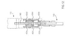
- FIG. 12presents a partial horizontal cross-sectional view of an exemplary flexible wrist-type element, in accordance with aspects of the present invention, in a position similar to that shown in FIG. 10 ;
- FIG. 13presents an exploded and disassembled view of various components of a portion of an exemplary drive train, in accordance with another variation of the present invention.
- FIG. 14shows another variation of an exemplary housing extension, in accordance with aspects of the present invention.
- FIG. 15shows another variation of an exemplary flexible coupling element and guide housing, in accordance with aspects of the present invention.
- FIG. 16shows another variation of an exemplary hub and guide, in accordance with aspects of the present invention.
- FIG. 17shows a view of an exemplary flexible wrist-type element using an exemplary constant velocity joint, in accordance with an aspect of the present invention.
- FIG. 18presents a partial cutaway view of one exemplary flexible wrist-type element, in accordance with aspects of the present invention, in a similar position to that shown in FIG. 17 .
- aspects of the present inventioninclude a flexible wrist-type element for use in surgical-related activities and methods of operation thereof, including variations having an angularly moveable hub housing, and a rotatable and operable end effector driven via additional elements in a drive train that may include one or more universal-type joints or other similarly flexible motion transmitting mechanisms.
- FIG. 1shows a perspective view of an exemplary flexible wrist-type element 100 , in accordance with aspects of the present invention.
- the flexible wrist-type element 100has a body housing 110 that is coupled to or otherwise operably engages a hub 120 .
- the hubmay move angularly relative to the housing 110 (compare, e.g., the position shown in FIG. 3 ) about, for example, one or more pivot points 150 .
- an end effector or other tool or component 140(also interchangeably and/or collectively referred to herein as an “end effector”) is engaged with the hub 120 , such as via a sleeve 130 that allows relative rotation with respect to the hub 120 .
- a drive system 191may be operative coupled to the wrist-type element 100 , wherein the 191 system generates forces for moving the hub 120 relative to the body housing 110 and/or for moving the end effector 140 , for example, to perform useful work.
- the body housing 110 , hub 120 , and end effector 140are shown positioned in approximately linear alignment along each of these elements' axial lengths in direction X 1 .
- a movement limiting travel mechanismsuch as a slot 112 in extension 111 extending from or attached to body housing 110 , which limits travel of a slidable guide track pin 165 , the operation of which will be described further below.
- FIG. 2shows the flexible wrist-type element 100 of FIG. 1 , with the end effector portion 140 rotated and in an “open” position (with regard to the two extensions 141 a , 141 b ), relative to the position shown in FIG. 1 .
- the sleeve 130is rotatable relative to the hub 120 , such as to the position shown.
- the sleeve 130may include one or more extensions, a lip, or other similar feature or features extending from its exterior surface for engagement with a receiving opening or other corresponding feature in the hub 120 .
- Other methods and/or featuresmay similarly be used to enable such relative rotational motion.
- FIG. 1shows the flexible wrist-type element 100 of FIG. 1 , with the end effector portion 140 rotated and in an “open” position (with regard to the two extensions 141 a , 141 b ), relative to the position shown in FIG. 1 .
- the sleeve 130is rotatable relative to the hub 120 , such as to the position shown.
- end effector portion 140may be manipulated, such as by moving arms or extensions 141 a , 141 b relative to each other (e.g., opening in directions D 1 , D 2 ). Further details of operation and control of sleeve 130 and end effector portion 140 will be described further below.
- FIG. 3shows a representative partial cutaway view of a portion of an exemplary sleeve 130 and hub 120 engageable in accordance with one exemplary variation of features so as to allow relative rotation therebetween.
- the sleeve 130has an extending lip 131 about its outer circumferential surface that is engageable within a groove 121 in the interior surface of the hub 120 , thereby allowing sliding rotation of the sleeve 130 relative to the hub 120 .
- FIG. 4shows an exemplary flexible wrist-type element 100 in accordance with aspects of the present invention similar to the device shown in FIG. 1 , that is oriented to a position such that the hub portion 120 is moved angularly to an angle A 3 relative to the body housing 110 .
- Such angular operationmay occur via a control rod or other tendon-like element, for example, not visible in FIG. 4 .
- the control rod or other tendon-like elementmay be a mechanism to transmit force, such as a link connected between the hub portion 120 and a bend actuator (not shown). Operation and control of the element 100 will be described further below.
- FIG. 5presents a partial cutaway view of an exemplary flexible wrist-type element 100 in a similar position to that shown in FIG. 1 .
- an input mechanisme.g., shaft
- Coupled to or otherwise operable via the input mechanism 180are one or more flexible couplings 400 , such as universal joints and/or Hooke's joints.
- increasing the number of couplings 400may increase the mechanical efficiency of the transmission of the axial forces through the couplings 400 when the hub portion 120 and/or end effector 140 is angled relative to the body housing 110 , as each additional coupling 400 reduces a relative joint angle between adjacent couplings, thereby improving axial force transmission.
- one or more guide housings 410may be may be movably connected to one or more of the flexible couplings 400 for securing and/or limiting the travel of one or more of the flexible couplings.
- at least one guide housing 410has or is attached to a travel limiting movement mechanism, such as pin 411 slidable within a guide 160 .
- a travel limiting movement mechanismsuch as pin 411 slidable within a guide 160 .
- three flexible couplings 400are coupled in series to the input mechanism 180 , and the guide 160 is secured at one end via a first pin 165 slidable within slot 112 and at a second end via a second pin 122 secured to the hub 120 .
- input mechanism 180comprises an input shaft coupled to the flexible coupling(s) 400 , which in this aspect includes three universal joints coupled in series, the flexible coupling(s) 400 being further coupled to the end effector 140 via an end effector shaft (one or more of the input mechanism 180 , the flexible couplings 400 , and/or parts of the end effector 140 interchangeably also being referred to herein as a “drive train”).
- the guide 160is secured and/or limited in movement at its two ends by a first pin 165 that travels within the slot 112 of extension 111 and by a second pin 122 attached to the hub 120 .
- the guide housing 410is coupled to the middle of the three universal joints in series.
- the guide housing 410includes an extending pin 411 that is limited in its travel by slot 161 of guide 160 . It is noted that, in the position shown in FIG. 5 , the first pin 165 is located near a first end of the slot 112 .
- the input shaft of the input mechanism 180may be moved (e.g., by sliding) with the flexible coupling(s) 400 (e.g., in direction S 41 as shown in FIG. 5 ).
- drive system 191may be coupled to the input mechanism 180 causing the input mechanism 180 to move.
- Drive system 191provides, at least one of axial force or torsional force to the couplings 440 .
- the drive system 191may include one or any combination of a hydraulic system, a magnetic system, a mechanical system, or an electrical system (e.g., servo motors), among other systems.
- the drive system 191comprises a manually-driven hydraulic system, such as a system operated by manual movements of a person, such as a surgeon, which move hydraulic fluid through tubes to generate the force or motion at input mechanism 180 .
- the force or motion of input mechanism 180in turn produces motion (e.g., in direction S 41 in the orientation of the device 100 shown in FIG. 5 ) of the flexible couplings, which may travel together with the guide housing 410 within the limits of slot 161 .
- the guide housing 410ensures that the three universal joints do not pivot significantly relative to one another in a direction other than the direction of travel (i.e., generally in direction S 41 as shown in FIG. 5 ).
- the motion in direction S 41 of the universal jointsmay in turn affect the end effector 140 , such as by causing the extensions 141 a , 141 b to open and close.
- the input shaft as shown in FIG. 5may also be rotated, for example, in directions R 41 , which in turn rotates the universal joints in corresponding directions R 42 and rotates the end effector in corresponding directions R 43 .
- FIG. 6shows a partial cutaway view of various elements of exemplary flexible couplings and a guide housing, in accordance with aspects of the present invention.
- the flexible coupling elements showninclude rigid connecting portions 401 , 402 coupled by a joint 403 , forming, for example, a universal-type joint.
- Angular or other motion of the portion 401 relative to the joint 403may occur, for example, via bearings 404 a , 404 b (e.g., ball bearings), and similarly between joint 403 and portion 402 .
- bearings 404 a , 404 be.g., ball bearings
- portion 401includes extensions 401 a , 401 b receivable within slot recess 410 a extending about the inner surface of generally cylindrically-shaped guide housing 410 .
- the assembly of portions 401 , 402 , and 403 and related componentsmay thereby rotate in direction R 45 , with extensions 401 a , 401 b traveling within slot 410 a.
- each of these elements 401 , 402 , 403 , 404 a , 404 bmay comprise a conductive material to enhance electrical communication therethrough.
- bearings 404 a , 404 bmay be lubricated by an electrically conductive lubricant.
- FIG. 7presents a partial cutaway view of an exemplary flexible wrist-type element 100 , in accordance with aspects of the present invention, oriented in a similar position to that shown in FIG. 4 .
- the guide 160is angularly moved to an angle A 51 for its lengthwise axis X 52 relative to the axis X 51 of input mechanism 180
- end effector 420is angularly moved to an angle A 52 for its lengthwise axis X 53 relative to the axis X 52 of the guide 160 .
- Such angled movement of the guide 160 and end effector 420 relative to input mechanism 180may be produced via operation of a control rod or other tendon-like mechanism, for example (not shown in FIG. 7 ).
- control rod or other tendon-like elementmay be a mechanism to transmit force, such as a link connected between the hub portion 120 and the body housing 110 , as shown in FIG. 17 below.
- extending pin 411in the position shown in FIG. 7 , is located at distance D 51 from a first end of slot 161
- pin 165is located a distance D 52 from the first end of the slot 112 .
- the movement of the pin 165 relative to the first end of the slot 112results from the angled movement of the hub 120 and end effector 140 relative to the housing body 110 .
- FIG. 8contains a partial cutaway view of an exemplary flexible wrist-type element 100 , in accordance with aspects of the present invention, having an angularly moved position of the hub 120 relative to the input mechanism 180 , in an orientation similar to that of FIG. 4 , with the end effector 140 in an open and first rotated position relative to that shown in FIG. 7 .
- input mechanism 180in the position shown in FIG. 8 , has slidably moved with flexible couplings 400 in the direction S 61 , so as to extend the flexible coupling(s) 400 to a position such that extending pin 411 has moved to a location near the first end of slot 161 .
- Guide housing 410along with flexible coupling(s) 400 , has correspondingly slid in direction S 62 , relative to the position shown in FIG. 7 .
- extensions 141 a , 141 bhave responsively moved from a first, more closed position as shown in FIG. 7 to a second, more open position, as shown in FIG. 8 .
- guide track pin 165is freely slidable in slot 112 of extension 111 , so that the overall drive train may slideably reach a least binding or otherwise suitable position via the pin 165 within slot 112 .
- rotational motionmay be communicated via the input mechanism 180 in the direction R 61 , which is communicated to the end effector 140 in direction R 63 via flexible coupling(s) 400 in direction R 62 .
- FIG. 9shows a partial cutaway view of the flexible wrist-type element 100 having the angularly moved position of the hub 120 relative to the body portion 110 as shown in FIG. 4 , with the end effector 140 in a closed position relative to that shown in FIG. 8 .
- FIG. 9shows that motion of the input mechanism 180 in the direction S 71 moved flexible coupling(s) 400 in the direction S 72 , as indicated.
- extensions 141 a , 141 bhave moved from the second, more open position ( FIG. 8 ) to the first, more closed position ( FIG. 9 ).
- guide track pin 165is again freely slidable in slot 112 of extension 111 , so that the overall drive train may slideably reach a least binding or otherwise suitable position.
- FIG. 10shows a side, partial cutaway section view of the flexible wrist-type element 100 in a position similar to that shown in FIG. 4 .
- the view of FIG. 10is similar to that of FIG. 8 , but more clearly shows the outer surface of the hub 120 and sleeve 130 .
- a part of the rigid connecting portion 401is visible in this view.
- FIGS. 11 and 12present a representative vertical and axial cross-sectional view of the flexible wrist-type element 100 in a position similar to that shown in FIG. 10 .
- Visible in the view of FIGS. 11 and 12are the rigid connecting portions 401 , 402 and bearings 404 a , 404 b spaced apart along a first axis and bearings 404 a ′ and 404 b ′ (not shown) spaced apart along a second axis, as well as other portions of flexible coupling elements, in accordance with aspects of the present invention.
- the second axis of bearings 404 c and 404 dis substantially perpendicular to the first axis of bearings 404 a and 404 b at each respective joint 403 (not shown).
- the rigid connecting portions 401 and 402include a shaft portion and an extension portion, such as a C-arm type or fork-like structure.
- each arm of the C-arm structureis movably connected to one pair of the spaced bearings on a given axis, such that adjacent C-arms lie in substantially perpendicular planes, thereby allowing each joint 403 to fix adjacent rigid structures to rotate together but to allow relative angular changes.
- one or joints 170 of the plurality of couplings in this aspectinclude a universal joint having a central block supporting horizontal and vertical pairs of ball bearings that movably connect to fork-like connector elements of the flexible coupling.
- joints 170allow for variable angular movement between coupling elements, and the joints 170 also transfer axial and torsional forces.
- Other U-joint designscould be used.
- FIG. 13presents an exploded and disassembled view of various components of a portion of an exemplary drive train, in accordance with another variation of the present invention.
- Element A of FIG. 13is an exemplary housing extension, which is further detailed in FIG. 14 .
- Element B of FIG. 13is an exemplary flexible coupling element and guide housing, which are further detailed in FIG. 15 .
- Element C of FIG. 13shows an exemplary hub and guide, and other portions relating thereto, as further detailed in FIG. 16 .
- the housing extensionincludes a “U” shaped main housing surrounding a shaft, e.g., a control rod, which extends through the center of the main housing.
- the shaftis coupled to the main housing via a flange bushing.
- the main housingalso includes a pair of movement limiting travel mechanisms, such as a slot, which limits travel of a pair of slidable roller pins.
- the slidable roller pinsare coupled to the slot via a custom bushing wheel.
- the slidable roller pinsare inserted into the custom bushing wheel.
- the slidable roller pinsare held within the custom bushing wheel via bearing shim spacers and a C-clip.
- the slidable roller pinsmove within a slot of an outer link (not shown). The movement of the slidable roller pin in the outer link limits the angular movement of the main housing.
- FIG. 15illustrated is an exemplary flexible coupling element and guide housing in accordance with an aspect of the present invention.
- the guide housing surrounding the chain of flexible couplingsincludes a pair of dowels coupled to opposite sides of the guide housing extending into a pair of bushing wheels.
- the pair of bushing wheelstravel within a slot of a guide track (not shown) limiting the movement of the chain of flexible couplings.
- a key retaineris coupled to the guide housing surrounding the chain of flexible couplings limiting the rotational movement of the flexible couplings.
- FIG. 16illustrated is another variation of an exemplary “U” shape hub and guide in accordance with aspects of the present invention.
- the hubsurrounds a shaft extending through the middle of the hub.
- a pair of U-joint guide link bracketsare coupled to the inside of the hub via a dowel extending through a pair of custom bushings. Each dowel is held within the custom bushings by bearing shim spacers and a C-clip.
- the U-joint guide link bracketsare connected to an outer link (not shown) limiting the movement of the hub by the dowels sliding in a slot of the outer link.
- the hubincludes a housing pivot end coupled to the outer link via a roller pin extending through the housing pivot end. The roller pin is inserted into bushing wheels and held in place with bearing shim spacers and a C-clip. The roller pin slides in the slot of the outer link limiting the movement of the housing pivot end.
- FIG. 17illustrates a view of an exemplary flexible wrist-type element 200 using a constant velocity Hooke's joint, in accordance with an aspect of the present invention.
- the flexible wrist-type element 200has a body housing 210 that is coupled to or otherwise operably engages a hub 220 .
- the hubmay move angularly relative to the housing 210 about, for example, one or more pivot points 250 .
- Such angular operationmay occur via a control rod or other tendon-like element, for example, a link 270 , which may be driven by a drive system similar to drive system 191 , as discussed above.
- the link 270may be secured at one end to the body housing 210 via a first pin 274 and secured to the hub 220 via a second pin 272 .
- An end effector or other tool or component 240(also interchangeably and/or collectively referred to herein as an “end effector”) is engaged with the hub 220 , such as via a sleeve 230 that allows relative rotation with respect to the hub 220 .
- housing body 210Extending from the interior of housing body 210 is an input mechanism (e.g., shaft) 280 . Coupled to or otherwise operable to the input mechanism 280 are one or more constant velocity joints 500 , as well as one or more guide housings 510 for securing and/or limiting the travel of one or more of the constant velocity joints 500 .
- Each constant velocity joint 500has a guide housing 510 or is otherwise attached to a travel limiting movement mechanism.
- the guide housing 510 coupled to the middle constant velocity joint 500has a support element or pin 511 slidable within a guide 260 for limiting the movement of the constant velocity joints 500 .
- three constant velocity joints 500are coupled in series to the input mechanism 280 , and the guide 260 is secured at one end via a first pin 265 slidable within slot 212 and at a second end via a second pin 222 secured to the hub 220 .
- FIG. 18illustrates a partial cutaway view of an exemplary flexible wrist-type element 200 in a similar position to that shown in FIG. 17 .
- an input mechanisme.g., shaft
- Three constant velocity joints 500are coupled in series to the input mechanism 280 .
- Each constant velocity joint 500may have a first portion 514 , such as a male end, and a second portion 512 , such as a female end, and a shaft 518 connecting the portions 514 and 516 . Further, each portion 514 and 516 has cooperating structure to allow the transfer of rotational forces and/or axial forces upon oblique positioning of the portions.
- the female portion 512may have an inner wall defining an opening sized to fit a corresponding male portion 514 .
- the male portions 514may have a rounded hexagonal shape and the female portions 512 may have a corresponding hexagonal shape opening.
- the male portions 514may be coupled to the female portions 512 , e.g., in a ball and socket arrangement, in alternating assemblies, as illustrated in FIG. 18 .
- the rounded hexagonal shape of the male portionallows the constant velocity joints to rotate in any direction. Additionally, the hexagonal shape of the male portion provides a transfer of torque to the shaft of the constant velocity joints. Additionally, it should be noted that a bearing may be positioned between the cooperating structures of the portions 514 and 516 .
- each constant velocity joint 500may also include a bearing 516 between the shaft 518 and the guide housing 510 . As such, the guide housings 510 may be coupled to the bearings 516 to allow relative rotation between the shaft 518 and the guide housing 510 .
- input mechanism 280comprises an input shaft coupled to the constant velocity joints 500 , which in this aspect includes three constant velocity joints coupled in series, the constant velocity joints 500 being further coupled to the end effector 240 via an end effector shaft (one or more of the input mechanism 280 , the constant velocity joints 500 , and/or parts of the end effector 240 interchangeably also being referred to herein as a “drive train”).
- the guide 260is secured and/or limited in movement at its two ends by a first pin 265 that travels within the slot 212 of extension 211 and by a second pin 222 attached to the hub 220 .
- the guide housing 510 coupled to the middle of the three constant velocity joints in seriesincludes an extending pin 511 that is limited in its travel by slot 261 of guide 260 . It is noted that, in the position shown in FIG. 15 , the first pin 265 is located near a first end of the slot 212 .
- the input shaft of the input mechanism 280may be moved (e.g., by sliding) toward and away from the constant velocity joints 500 (e.g., in direction S 41 as shown in FIG. 17 ).
- a drive system 191e.g., hydraulic, mechanical, magnetic and/or electrical
- This motionin turn produces motion (e.g., in direction S 41 in the orientation of the device 200 shown in FIG. 17 ) of the constant velocity joints, which may travel together with the guide housing 510 within the limits of slot 261 .
- the guide housing 510ensures that the three constant velocity joints do not pivot significantly relative to one another in a direction other than the direction of travel (i.e., generally in direction S 41 as shown in FIG. 17 ).
- the motion in direction S 41 of the universal jointsmay in turn affect the end effector 240 , such as by causing the extensions 241 a , 241 b to open and close.
- the input shaft 280 as shown in FIG. 17may also be rotated, for example, in directions R 41 , which in one aspect correspondingly rotates the constant velocity joints and the end effector in the same direction, however, the connections may also be setup such that rotation of input shaft 280 in one direction causes the joints and/or the end effector to rotate in an opposite direction.
- a rotational inputmay be transferred to either a rotational or axial output
- an axial inputmay be transferred to either an axial or rotational output, depending on a configuration of the connecting structures.
- Another variation of aspects of the present inventionincludes using two flexible coupling members in a chain connected to an input mechanism and an end effector. This aspect may not require a guide housing surrounding the flexible coupling members.
Landscapes
- Engineering & Computer Science (AREA)
- Health & Medical Sciences (AREA)
- Robotics (AREA)
- Surgery (AREA)
- Life Sciences & Earth Sciences (AREA)
- Mechanical Engineering (AREA)
- Medical Informatics (AREA)
- Heart & Thoracic Surgery (AREA)
- Biomedical Technology (AREA)
- Molecular Biology (AREA)
- Animal Behavior & Ethology (AREA)
- General Health & Medical Sciences (AREA)
- Public Health (AREA)
- Veterinary Medicine (AREA)
- General Engineering & Computer Science (AREA)
- Nuclear Medicine, Radiotherapy & Molecular Imaging (AREA)
- Manipulator (AREA)
- Surgical Instruments (AREA)
- Sampling And Sample Adjustment (AREA)
Abstract
Description
Claims (29)
Priority Applications (2)
| Application Number | Priority Date | Filing Date | Title |
|---|---|---|---|
| US12/493,967US8398619B2 (en) | 2008-06-27 | 2009-06-29 | Flexible wrist-type element and methods of manufacture and use thereof |
| US12/792,672US8784404B2 (en) | 2009-06-29 | 2010-06-02 | Flexible wrist-type element and methods of manufacture and use thereof |
Applications Claiming Priority (2)
| Application Number | Priority Date | Filing Date | Title |
|---|---|---|---|
| US7643208P | 2008-06-27 | 2008-06-27 | |
| US12/493,967US8398619B2 (en) | 2008-06-27 | 2009-06-29 | Flexible wrist-type element and methods of manufacture and use thereof |
Related Child Applications (1)
| Application Number | Title | Priority Date | Filing Date |
|---|---|---|---|
| US12/792,672Continuation-In-PartUS8784404B2 (en) | 2009-06-29 | 2010-06-02 | Flexible wrist-type element and methods of manufacture and use thereof |
Publications (2)
| Publication Number | Publication Date |
|---|---|
| US20090320637A1 US20090320637A1 (en) | 2009-12-31 |
| US8398619B2true US8398619B2 (en) | 2013-03-19 |
Family
ID=41444995
Family Applications (1)
| Application Number | Title | Priority Date | Filing Date |
|---|---|---|---|
| US12/493,967Active2032-01-18US8398619B2 (en) | 2008-06-27 | 2009-06-29 | Flexible wrist-type element and methods of manufacture and use thereof |
Country Status (12)
| Country | Link |
|---|---|
| US (1) | US8398619B2 (en) |
| EP (1) | EP2300724A1 (en) |
| JP (1) | JP2011526219A (en) |
| KR (1) | KR20110052572A (en) |
| CN (1) | CN102084141A (en) |
| AU (1) | AU2009261935A1 (en) |
| BR (1) | BRPI0910138A2 (en) |
| CA (1) | CA2727870A1 (en) |
| MX (1) | MX2010013735A (en) |
| RU (1) | RU2011102169A (en) |
| WO (1) | WO2009158708A1 (en) |
| ZA (1) | ZA201100618B (en) |
Cited By (10)
| Publication number | Priority date | Publication date | Assignee | Title |
|---|---|---|---|---|
| US20100331857A1 (en)* | 2009-06-29 | 2010-12-30 | Mark Doyle | Flexible wrist-type element and methods of manufacture and use thereof |
| US20120022554A1 (en)* | 2009-04-03 | 2012-01-26 | Jamie Paik | Surgical instrument |
| US8845622B2 (en) | 2009-04-03 | 2014-09-30 | Universite Pierre Et Marie Curie (Paris 6) | Surgical instrument |
| WO2015152972A1 (en) | 2014-03-31 | 2015-10-08 | Covidien Lp | Wrist and jaw assemblies for robotic surgical systems |
| US10061899B2 (en) | 2008-07-09 | 2018-08-28 | Baxter International Inc. | Home therapy machine |
| US10258359B2 (en) | 2014-08-13 | 2019-04-16 | Covidien Lp | Robotically controlling mechanical advantage gripping |
| US10390853B2 (en) | 2014-08-13 | 2019-08-27 | Covidien Lp | Robotically controlling mechanical advantage gripping |
| US10582975B2 (en) | 2015-10-16 | 2020-03-10 | Medical Microinstruments S.p.A. | Surgical tool |
| US10667873B2 (en) | 2015-06-23 | 2020-06-02 | Covidien Lp | Surgical end effectors with mechanical advantage |
| USD904611S1 (en) | 2018-10-10 | 2020-12-08 | Bolder Surgical, Llc | Jaw design for a surgical instrument |
Families Citing this family (22)
| Publication number | Priority date | Publication date | Assignee | Title |
|---|---|---|---|---|
| US8968276B2 (en)* | 2007-09-21 | 2015-03-03 | Covidien Lp | Hand held surgical handle assembly, surgical adapters for use between surgical handle assembly and surgical end effectors, and methods of use |
| US9055943B2 (en) | 2007-09-21 | 2015-06-16 | Covidien Lp | Hand held surgical handle assembly, surgical adapters for use between surgical handle assembly and surgical end effectors, and methods of use |
| US8534983B2 (en)* | 2008-03-17 | 2013-09-17 | Irobot Corporation | Door breaching robotic manipulator |
| KR101072818B1 (en)* | 2009-03-16 | 2011-10-14 | 한국과학기술원 | Manipulators with Distributed Actuation Mechanism |
| EP2580030A4 (en)* | 2010-06-10 | 2017-04-19 | Care Fusion 2200, Inc. | Flexible wrist-type element |
| WO2012074564A1 (en) | 2010-12-02 | 2012-06-07 | Freehand Endoscopic Devices, Inc. | Surgical tool |
| WO2012142587A1 (en) | 2011-04-15 | 2012-10-18 | Irobot Corporation | Method for path generation for an end effector of a robot |
| US9211134B2 (en) | 2012-04-09 | 2015-12-15 | Carefusion 2200, Inc. | Wrist assembly for articulating laparoscopic surgical instruments |
| ITTO20120425A1 (en)* | 2012-05-11 | 2013-11-12 | Dalmec Spa | BALANCED PNEUMATIC MANIPULATOR |
| DE102013005982A1 (en)* | 2013-04-08 | 2014-10-09 | Kuka Laboratories Gmbh | medical robots |
| CN104139398B (en)* | 2013-05-10 | 2016-03-16 | 上海工程技术大学 | Flexible Miniature wrist |
| US9693774B2 (en) | 2014-06-25 | 2017-07-04 | Ethicon Llc | Pivotable articulation joint unlocking feature for surgical stapler |
| CN108882933B (en)* | 2016-02-09 | 2021-07-23 | 伊西康有限责任公司 | Surgical instrument articulation mechanism with slotted secondary constraint |
| US11234700B2 (en) | 2016-09-09 | 2022-02-01 | Intuitive Surgical Operations, Inc. | Wrist architecture |
| JP6811676B2 (en)* | 2017-05-01 | 2021-01-13 | 株式会社メディカロイド | Drive member, drive mechanism, and manufacturing method of drive mechanism |
| US11446046B2 (en)* | 2017-08-26 | 2022-09-20 | Nutech Ventures | Tool exchange system for a surgical robot |
| CN109352619B (en)* | 2018-10-25 | 2021-07-06 | 北京石油化工学院 | Link device and method of use |
| DE102019103493A1 (en) | 2019-02-12 | 2020-08-13 | Karl Storz Se & Co. Kg | Medical instrument |
| CN110116422A (en)* | 2019-04-29 | 2019-08-13 | 天津大学 | A kind of double drive multimode software end attachment device |
| CN111997986B (en)* | 2020-07-24 | 2021-04-30 | 河南科技大学第一附属医院 | Instrument connection structure for operation |
| CN112248018A (en)* | 2020-10-13 | 2021-01-22 | 武汉轻工大学 | A flexible gripper and manipulator |
| JP2024502276A (en)* | 2020-12-22 | 2024-01-18 | ヴィカリアス・サージカル・インコーポレイテッド | System and method for implementing multi-turn rotation concepts in actuator mechanisms of surgical robotic arms |
Citations (87)
| Publication number | Priority date | Publication date | Assignee | Title |
|---|---|---|---|---|
| US4848338A (en) | 1987-01-20 | 1989-07-18 | Minnesota Mining And Manufacturing Company | Hydraulically operated surgical instrument |
| US5456684A (en) | 1994-09-08 | 1995-10-10 | Hutchinson Technology Incorporated | Multifunctional minimally invasive surgical instrument |
| US5496317A (en) | 1993-05-04 | 1996-03-05 | Gyrus Medical Limited | Laparoscopic surgical instrument |
| US5575799A (en) | 1995-03-30 | 1996-11-19 | United States Surgical Corporation | Articulating surgical apparatus |
| US5599350A (en) | 1995-04-03 | 1997-02-04 | Ethicon Endo-Surgery, Inc. | Electrosurgical clamping device with coagulation feedback |
| US5611813A (en) | 1992-04-15 | 1997-03-18 | Microsurge, Inc. | Surgical instrument |
| US5618307A (en) | 1995-04-03 | 1997-04-08 | Heartport, Inc. | Clamp assembly and method of use |
| US5700261A (en) | 1996-03-29 | 1997-12-23 | Ethicon Endo-Surgery, Inc. | Bipolar Scissors |
| US5746759A (en) | 1992-06-24 | 1998-05-05 | Microsurge, Inc. | Reusable endoscopic surgical instrument |
| US5746740A (en) | 1992-09-23 | 1998-05-05 | United States Surgical Corporation | Surgical biopsy forceps apparatus |
| US5752972A (en) | 1995-11-09 | 1998-05-19 | Hoogeboom; Thomas J. | Modular endoscopic surgical instrument |
| US5791231A (en) | 1993-05-17 | 1998-08-11 | Endorobotics Corporation | Surgical robotic system and hydraulic actuator therefor |
| US5797941A (en) | 1995-02-01 | 1998-08-25 | Ethicon Endo-Surgery, Inc. | Surgical instrument with expandable cutting element |
| US5820623A (en) | 1995-06-20 | 1998-10-13 | Ng; Wan Sing | Articulated arm for medical procedures |
| US5876410A (en) | 1996-07-22 | 1999-03-02 | Phillip J. Petillo | Hydraulic powered surgical device |
| US5931832A (en) | 1993-05-14 | 1999-08-03 | Sri International | Methods for positioning a surgical instrument about a remote spherical center of rotation |
| US6024695A (en) | 1991-06-13 | 2000-02-15 | International Business Machines Corporation | System and method for augmentation of surgery |
| US6102909A (en) | 1997-08-26 | 2000-08-15 | Ethicon, Inc. | Scissorlike electrosurgical cutting instrument |
| US6179837B1 (en) | 1995-03-07 | 2001-01-30 | Enable Medical Corporation | Bipolar electrosurgical scissors |
| US6197017B1 (en) | 1998-02-24 | 2001-03-06 | Brock Rogers Surgical, Inc. | Articulated apparatus for telemanipulator system |
| US6223100B1 (en) | 1992-01-21 | 2001-04-24 | Sri, International | Apparatus and method for performing computer enhanced surgery with articulated instrument |
| US6296635B1 (en) | 1996-02-08 | 2001-10-02 | Symbiosis Corporation | Endoscopic robotic surgical tools and methods |
| US6309397B1 (en) | 1999-12-02 | 2001-10-30 | Sri International | Accessories for minimally invasive robotic surgery and methods |
| US6346072B1 (en) | 1996-12-12 | 2002-02-12 | Intuitive Surgical, Inc. | Multi-component telepresence system and method |
| US6371952B1 (en) | 1996-05-20 | 2002-04-16 | Intuitive Surgical, Inc. | Articulated surgical instrument for performing minimally invasive surgery with enhanced dexterity and sensitivity |
| US6391029B1 (en) | 1995-03-07 | 2002-05-21 | Enable Medical Corporation | Bipolar electrosurgical scissors |
| US6398726B1 (en) | 1998-11-20 | 2002-06-04 | Intuitive Surgical, Inc. | Stabilizer for robotic beating-heart surgery |
| US6424885B1 (en) | 1999-04-07 | 2002-07-23 | Intuitive Surgical, Inc. | Camera referenced control in a minimally invasive surgical apparatus |
| US6434329B1 (en) | 1999-05-13 | 2002-08-13 | L'universite De Montreal | Controllable camera support and system |
| US6432112B2 (en) | 1998-02-24 | 2002-08-13 | Brock Rogers Surgical, Inc. | Articulated apparatus for telemanipulator system |
| US6441577B2 (en) | 1998-08-04 | 2002-08-27 | Intuitive Surgical, Inc. | Manipulator positioning linkage for robotic surgery |
| US20020120252A1 (en) | 1998-02-24 | 2002-08-29 | Brock David L. | Surgical instrument |
| US6468265B1 (en) | 1998-11-20 | 2002-10-22 | Intuitive Surgical, Inc. | Performing cardiac surgery without cardioplegia |
| US6488265B2 (en) | 2000-03-01 | 2002-12-03 | Hale Products, Inc. | Ball valve assembly |
| US6491691B1 (en) | 1999-10-08 | 2002-12-10 | Intuitive Surgical, Inc. | Minimally invasive surgical hook apparatus and method for using same |
| US6554844B2 (en) | 1998-02-24 | 2003-04-29 | Endovia Medical, Inc. | Surgical instrument |
| US20030083673A1 (en) | 1998-12-08 | 2003-05-01 | Intuitive Surgical, Inc. | Mechanical actuator interface system for robotic surgical tools |
| US6574355B2 (en) | 1992-01-21 | 2003-06-03 | Intuitive Surigical, Inc. | Method and apparatus for transforming coordinate systems in a telemanipulation system |
| US20030135204A1 (en) | 2001-02-15 | 2003-07-17 | Endo Via Medical, Inc. | Robotically controlled medical instrument with a flexible section |
| US6620174B2 (en) | 1995-06-07 | 2003-09-16 | Sri International | Surgical manipulator for a telerobotic system |
| US6622980B2 (en) | 2000-03-28 | 2003-09-23 | Hill-Rom Services, Inc. | Socket and rail clamp apparatus |
| US20030216715A1 (en) | 1998-11-20 | 2003-11-20 | Intuitive Surgical, Inc. | Cooperative minimally invasive telesurgical system |
| US6665554B1 (en) | 1998-11-18 | 2003-12-16 | Steve T. Charles | Medical manipulator for use with an imaging device |
| US20030236549A1 (en) | 2000-07-21 | 2003-12-25 | Frank Bonadio | Surgical instrument |
| US6676684B1 (en) | 2001-09-04 | 2004-01-13 | Intuitive Surgical, Inc. | Roll-pitch-roll-yaw surgical tool |
| US6676669B2 (en) | 2001-01-16 | 2004-01-13 | Microdexterity Systems, Inc. | Surgical manipulator |
| US6702805B1 (en) | 1999-11-12 | 2004-03-09 | Microdexterity Systems, Inc. | Manipulator |
| US6723106B1 (en) | 1998-11-23 | 2004-04-20 | Microdexterity Systems, Inc. | Surgical manipulator |
| US6723087B2 (en) | 2001-12-14 | 2004-04-20 | Medtronic, Inc. | Apparatus and method for performing surgery on a patient |
| US6731988B1 (en) | 1992-01-21 | 2004-05-04 | Sri International | System and method for remote endoscopic surgery |
| US6746443B1 (en) | 2000-07-27 | 2004-06-08 | Intuitive Surgical Inc. | Roll-pitch-roll surgical tool |
| US6755338B2 (en) | 2001-08-29 | 2004-06-29 | Cerebral Vascular Applications, Inc. | Medical instrument |
| US6770081B1 (en) | 2000-01-07 | 2004-08-03 | Intuitive Surgical, Inc. | In vivo accessories for minimally invasive robotic surgery and methods |
| US6776783B1 (en) | 1999-01-08 | 2004-08-17 | Cardiothoracic Systems, Inc. | Surgical clips and apparatus and method for clip placement |
| US6783524B2 (en) | 2001-04-19 | 2004-08-31 | Intuitive Surgical, Inc. | Robotic surgical tool with ultrasound cauterizing and cutting instrument |
| US6786896B1 (en) | 1997-09-19 | 2004-09-07 | Massachusetts Institute Of Technology | Robotic apparatus |
| US6788018B1 (en) | 1999-08-03 | 2004-09-07 | Intuitive Surgical, Inc. | Ceiling and floor mounted surgical robot set-up arms |
| US6788999B2 (en) | 1992-01-21 | 2004-09-07 | Sri International, Inc. | Surgical system |
| US20040193146A1 (en) | 2001-02-15 | 2004-09-30 | Endo Via Medical, Inc. | Robotically controlled surgical instruments |
| US6817974B2 (en) | 2001-06-29 | 2004-11-16 | Intuitive Surgical, Inc. | Surgical tool having positively positionable tendon-actuated multi-disk wrist joint |
| US6827725B2 (en) | 2001-05-10 | 2004-12-07 | Gyrus Medical Limited | Surgical instrument |
| US6830174B2 (en) | 2000-08-30 | 2004-12-14 | Cerebral Vascular Applications, Inc. | Medical instrument |
| US6840938B1 (en) | 2000-12-29 | 2005-01-11 | Intuitive Surgical, Inc. | Bipolar cauterizing instrument |
| US6850817B1 (en) | 1992-01-21 | 2005-02-01 | Sri International | Surgical system |
| US6860878B2 (en) | 1998-02-24 | 2005-03-01 | Endovia Medical Inc. | Interchangeable instrument |
| US6879880B2 (en) | 1999-04-07 | 2005-04-12 | Intuitive Surgical, Inc. | Grip strength with tactile feedback for robotic surgery |
| US6936042B2 (en) | 1999-01-22 | 2005-08-30 | Intuitive Surgical | Surgical tools for use in minimally invasive telesurgical applications |
| US20050228440A1 (en) | 1999-05-10 | 2005-10-13 | Endovia Medical Inc. | Surgical instrument |
| US6994708B2 (en) | 2001-04-19 | 2006-02-07 | Intuitive Surgical | Robotic tool with monopolar electro-surgical scissors |
| US7063697B2 (en) | 1994-12-13 | 2006-06-20 | Symbiosis Corporation | Bipolar endoscopic surgical scissor blades and instrument incorporating the same |
| US7083615B2 (en) | 2003-02-24 | 2006-08-01 | Intuitive Surgical Inc | Surgical tool having electrocautery energy supply conductor with inhibited current leakage |
| US7083618B2 (en) | 2001-04-06 | 2006-08-01 | Sherwood Services Ag | Vessel sealer and divider |
| US7090683B2 (en) | 1998-02-24 | 2006-08-15 | Hansen Medical, Inc. | Flexible instrument |
| US7101371B2 (en) | 2001-04-06 | 2006-09-05 | Dycus Sean T | Vessel sealer and divider |
| US7108688B2 (en) | 1993-05-14 | 2006-09-19 | Sri International | Remote center positioner |
| US7125403B2 (en) | 1998-12-08 | 2006-10-24 | Intuitive Surgical | In vivo accessories for minimally invasive robotic surgery |
| US7155316B2 (en) | 2002-08-13 | 2006-12-26 | Microbotics Corporation | Microsurgical robot system |
| US20070021776A1 (en) | 1995-06-07 | 2007-01-25 | Sri International | System and method for releasably holding a surgical instrument |
| US7169141B2 (en) | 1998-02-24 | 2007-01-30 | Hansen Medical, Inc. | Surgical instrument |
| US20070088340A1 (en) | 1998-02-24 | 2007-04-19 | Hansen Medical, Inc. | Surgical instruments |
| US7246734B2 (en) | 2005-12-05 | 2007-07-24 | Ethicon Endo-Surgery, Inc. | Rotary hydraulic pump actuated multi-stroke surgical instrument |
| US7250028B2 (en) | 1999-11-09 | 2007-07-31 | Intuitive Surgical Inc | Endoscopic beating-heart stabilizer and vessel occlusion fastener |
| US7252660B2 (en) | 2001-09-25 | 2007-08-07 | Reiner Kunz | Multifunctional instrument for use in microinvasive surgery |
| US20070233052A1 (en) | 1998-02-24 | 2007-10-04 | Hansen Medical, Inc. | Interchangeable surgical instrument |
| US7297142B2 (en) | 1998-02-24 | 2007-11-20 | Hansen Medical, Inc. | Interchangeable surgical instrument |
| US7320700B2 (en) | 2002-12-06 | 2008-01-22 | Intuitive Surgical, Inc | Flexible wrist for surgical tool |
| US20080033453A1 (en) | 1998-02-24 | 2008-02-07 | Hansen Medical, Inc. | Interchangeable surgical instrument |
Family Cites Families (8)
| Publication number | Priority date | Publication date | Assignee | Title |
|---|---|---|---|---|
| US3916701A (en)* | 1973-04-17 | 1975-11-04 | Automation Prod | Rotary wrist actuator for industrial robots |
| GB8503547D0 (en)* | 1985-02-12 | 1985-03-13 | British Petroleum Co Plc | Nozzle |
| US5551775A (en)* | 1994-02-22 | 1996-09-03 | Accuride International, Inc. | Telescopic drawer slide with mechanical sequencing latch |
| GB0114406D0 (en)* | 2001-06-13 | 2001-08-08 | Oliver Crispin Consulting Ltd | Improvements in and relating to robotic arms |
| US20060199999A1 (en)* | 2001-06-29 | 2006-09-07 | Intuitive Surgical Inc. | Cardiac tissue ablation instrument with flexible wrist |
| JP2004154877A (en)* | 2002-11-05 | 2004-06-03 | Japan Science & Technology Agency | Bending mechanism with multi-joint slider link |
| JP4618769B2 (en)* | 2003-12-18 | 2011-01-26 | 国立大学法人 東京大学 | Rotating telescopic link mechanism |
| JP4755047B2 (en)* | 2006-08-08 | 2011-08-24 | テルモ株式会社 | Working mechanism and manipulator |
- 2009
- 2009-06-29RURU2011102169/14Apatent/RU2011102169A/ennot_activeApplication Discontinuation
- 2009-06-29USUS12/493,967patent/US8398619B2/enactiveActive
- 2009-06-29EPEP09771239Apatent/EP2300724A1/ennot_activeWithdrawn
- 2009-06-29MXMX2010013735Apatent/MX2010013735A/ennot_activeApplication Discontinuation
- 2009-06-29CACA2727870Apatent/CA2727870A1/ennot_activeAbandoned
- 2009-06-29JPJP2011516768Apatent/JP2011526219A/enactivePending
- 2009-06-29WOPCT/US2009/049067patent/WO2009158708A1/enactiveApplication Filing
- 2009-06-29BRBRPI0910138Apatent/BRPI0910138A2/ennot_activeIP Right Cessation
- 2009-06-29CNCN200980124699XApatent/CN102084141A/enactivePending
- 2009-06-29AUAU2009261935Apatent/AU2009261935A1/ennot_activeAbandoned
- 2009-06-29KRKR1020117000998Apatent/KR20110052572A/ennot_activeWithdrawn
- 2011
- 2011-01-25ZAZA2011/00618Apatent/ZA201100618B/enunknown
Patent Citations (117)
| Publication number | Priority date | Publication date | Assignee | Title |
|---|---|---|---|---|
| US4848338A (en) | 1987-01-20 | 1989-07-18 | Minnesota Mining And Manufacturing Company | Hydraulically operated surgical instrument |
| US6024695A (en) | 1991-06-13 | 2000-02-15 | International Business Machines Corporation | System and method for augmentation of surgery |
| US6999852B2 (en) | 1992-01-21 | 2006-02-14 | Sri International | Flexible robotic surgery system and method |
| US6963792B1 (en) | 1992-01-21 | 2005-11-08 | Sri International | Surgical method |
| US7107124B2 (en) | 1992-01-21 | 2006-09-12 | Sri International | Roll-pitch-roll wrist methods for minimally invasive robotic surgery |
| US7248944B2 (en) | 1992-01-21 | 2007-07-24 | Institute Surgical, Inc | Roll-pitch-roll wrist methods for minimally invasive robotic surgery |
| US7006895B2 (en) | 1992-01-21 | 2006-02-28 | Sri International | Computed pivotal center surgical robotic system and method |
| US6788999B2 (en) | 1992-01-21 | 2004-09-07 | Sri International, Inc. | Surgical system |
| US6574355B2 (en) | 1992-01-21 | 2003-06-03 | Intuitive Surigical, Inc. | Method and apparatus for transforming coordinate systems in a telemanipulation system |
| US6850817B1 (en) | 1992-01-21 | 2005-02-01 | Sri International | Surgical system |
| US6731988B1 (en) | 1992-01-21 | 2004-05-04 | Sri International | System and method for remote endoscopic surgery |
| US6223100B1 (en) | 1992-01-21 | 2001-04-24 | Sri, International | Apparatus and method for performing computer enhanced surgery with articulated instrument |
| US5620459A (en) | 1992-04-15 | 1997-04-15 | Microsurge, Inc. | Surgical instrument |
| US5611813A (en) | 1992-04-15 | 1997-03-18 | Microsurge, Inc. | Surgical instrument |
| US5746759A (en) | 1992-06-24 | 1998-05-05 | Microsurge, Inc. | Reusable endoscopic surgical instrument |
| US5746740A (en) | 1992-09-23 | 1998-05-05 | United States Surgical Corporation | Surgical biopsy forceps apparatus |
| US5496317A (en) | 1993-05-04 | 1996-03-05 | Gyrus Medical Limited | Laparoscopic surgical instrument |
| US5931832A (en) | 1993-05-14 | 1999-08-03 | Sri International | Methods for positioning a surgical instrument about a remote spherical center of rotation |
| US7108688B2 (en) | 1993-05-14 | 2006-09-19 | Sri International | Remote center positioner |
| US5791231A (en) | 1993-05-17 | 1998-08-11 | Endorobotics Corporation | Surgical robotic system and hydraulic actuator therefor |
| US5456684A (en) | 1994-09-08 | 1995-10-10 | Hutchinson Technology Incorporated | Multifunctional minimally invasive surgical instrument |
| US7063697B2 (en) | 1994-12-13 | 2006-06-20 | Symbiosis Corporation | Bipolar endoscopic surgical scissor blades and instrument incorporating the same |
| US5797941A (en) | 1995-02-01 | 1998-08-25 | Ethicon Endo-Surgery, Inc. | Surgical instrument with expandable cutting element |
| US6391029B1 (en) | 1995-03-07 | 2002-05-21 | Enable Medical Corporation | Bipolar electrosurgical scissors |
| US6179837B1 (en) | 1995-03-07 | 2001-01-30 | Enable Medical Corporation | Bipolar electrosurgical scissors |
| US5575799A (en) | 1995-03-30 | 1996-11-19 | United States Surgical Corporation | Articulating surgical apparatus |
| US5618307A (en) | 1995-04-03 | 1997-04-08 | Heartport, Inc. | Clamp assembly and method of use |
| US5599350A (en) | 1995-04-03 | 1997-02-04 | Ethicon Endo-Surgery, Inc. | Electrosurgical clamping device with coagulation feedback |
| US6620174B2 (en) | 1995-06-07 | 2003-09-16 | Sri International | Surgical manipulator for a telerobotic system |
| US20070021776A1 (en) | 1995-06-07 | 2007-01-25 | Sri International | System and method for releasably holding a surgical instrument |
| US7204844B2 (en) | 1995-06-07 | 2007-04-17 | Sri, International | System and method for releasably holding a surgical instrument |
| US5820623A (en) | 1995-06-20 | 1998-10-13 | Ng; Wan Sing | Articulated arm for medical procedures |
| US5752972A (en) | 1995-11-09 | 1998-05-19 | Hoogeboom; Thomas J. | Modular endoscopic surgical instrument |
| US6296635B1 (en) | 1996-02-08 | 2001-10-02 | Symbiosis Corporation | Endoscopic robotic surgical tools and methods |
| US5700261A (en) | 1996-03-29 | 1997-12-23 | Ethicon Endo-Surgery, Inc. | Bipolar Scissors |
| US7316681B2 (en) | 1996-05-20 | 2008-01-08 | Intuitive Surgical, Inc | Articulated surgical instrument for performing minimally invasive surgery with enhanced dexterity and sensitivity |
| US6371952B1 (en) | 1996-05-20 | 2002-04-16 | Intuitive Surgical, Inc. | Articulated surgical instrument for performing minimally invasive surgery with enhanced dexterity and sensitivity |
| US6991627B2 (en) | 1996-05-20 | 2006-01-31 | Intuitive Surgical Inc. | Articulated surgical instrument for performing minimally invasive surgery with enhanced dexterity and sensitivity |
| US5876410A (en) | 1996-07-22 | 1999-03-02 | Phillip J. Petillo | Hydraulic powered surgical device |
| US6099536A (en) | 1996-07-22 | 2000-08-08 | Pacific Surgical Innovations | Hydraulic powered surgical device |
| US6866671B2 (en) | 1996-12-12 | 2005-03-15 | Intuitive Surgical, Inc. | Surgical robotic tools, data architecture, and use |
| US20050149003A1 (en) | 1996-12-12 | 2005-07-07 | Intuitive Surgical , Inc. | Surgical robotic tools, data architecture, and use |
| US6346072B1 (en) | 1996-12-12 | 2002-02-12 | Intuitive Surgical, Inc. | Multi-component telepresence system and method |
| US20070012135A1 (en) | 1996-12-12 | 2007-01-18 | Intuitive Surgical Inc. | Surgical robotic tools, data architecture, and use |
| US6102909A (en) | 1997-08-26 | 2000-08-15 | Ethicon, Inc. | Scissorlike electrosurgical cutting instrument |
| US6361534B1 (en) | 1997-08-26 | 2002-03-26 | Ethicon, Inc. | Electrosurgical cutting instrument |
| US6786896B1 (en) | 1997-09-19 | 2004-09-07 | Massachusetts Institute Of Technology | Robotic apparatus |
| US7090683B2 (en) | 1998-02-24 | 2006-08-15 | Hansen Medical, Inc. | Flexible instrument |
| US6197017B1 (en) | 1998-02-24 | 2001-03-06 | Brock Rogers Surgical, Inc. | Articulated apparatus for telemanipulator system |
| US20070088340A1 (en) | 1998-02-24 | 2007-04-19 | Hansen Medical, Inc. | Surgical instruments |
| US7297142B2 (en) | 1998-02-24 | 2007-11-20 | Hansen Medical, Inc. | Interchangeable surgical instrument |
| US6692485B1 (en) | 1998-02-24 | 2004-02-17 | Endovia Medical, Inc. | Articulated apparatus for telemanipulator system |
| US20080033453A1 (en) | 1998-02-24 | 2008-02-07 | Hansen Medical, Inc. | Interchangeable surgical instrument |
| US6432112B2 (en) | 1998-02-24 | 2002-08-13 | Brock Rogers Surgical, Inc. | Articulated apparatus for telemanipulator system |
| US20070233052A1 (en) | 1998-02-24 | 2007-10-04 | Hansen Medical, Inc. | Interchangeable surgical instrument |
| US20050215983A1 (en) | 1998-02-24 | 2005-09-29 | Endo Via Medical, Inc. | Interchangeable instrument |
| US7169141B2 (en) | 1998-02-24 | 2007-01-30 | Hansen Medical, Inc. | Surgical instrument |
| US6843793B2 (en) | 1998-02-24 | 2005-01-18 | Endovia Medical, Inc. | Surgical instrument |
| US20020120252A1 (en) | 1998-02-24 | 2002-08-29 | Brock David L. | Surgical instrument |
| US6860878B2 (en) | 1998-02-24 | 2005-03-01 | Endovia Medical Inc. | Interchangeable instrument |
| US6554844B2 (en) | 1998-02-24 | 2003-04-29 | Endovia Medical, Inc. | Surgical instrument |
| US6441577B2 (en) | 1998-08-04 | 2002-08-27 | Intuitive Surgical, Inc. | Manipulator positioning linkage for robotic surgery |
| US6665554B1 (en) | 1998-11-18 | 2003-12-16 | Steve T. Charles | Medical manipulator for use with an imaging device |
| US6398726B1 (en) | 1998-11-20 | 2002-06-04 | Intuitive Surgical, Inc. | Stabilizer for robotic beating-heart surgery |
| US6764445B2 (en) | 1998-11-20 | 2004-07-20 | Intuitive Surgical, Inc. | Stabilizer for robotic beating-heart surgery |
| US6468265B1 (en) | 1998-11-20 | 2002-10-22 | Intuitive Surgical, Inc. | Performing cardiac surgery without cardioplegia |
| US20030216715A1 (en) | 1998-11-20 | 2003-11-20 | Intuitive Surgical, Inc. | Cooperative minimally invasive telesurgical system |
| US6723106B1 (en) | 1998-11-23 | 2004-04-20 | Microdexterity Systems, Inc. | Surgical manipulator |
| US20070093792A1 (en) | 1998-12-08 | 2007-04-26 | Intuitive Surgical Inc. | In vivo accessories for minimally invasive robotic surgery |
| US20030083673A1 (en) | 1998-12-08 | 2003-05-01 | Intuitive Surgical, Inc. | Mechanical actuator interface system for robotic surgical tools |
| US7125403B2 (en) | 1998-12-08 | 2006-10-24 | Intuitive Surgical | In vivo accessories for minimally invasive robotic surgery |
| US7048745B2 (en) | 1998-12-08 | 2006-05-23 | Intuitive Surgical | Surgical robotic tools, data architecture, and use |
| US6776783B1 (en) | 1999-01-08 | 2004-08-17 | Cardiothoracic Systems, Inc. | Surgical clips and apparatus and method for clip placement |
| US6936042B2 (en) | 1999-01-22 | 2005-08-30 | Intuitive Surgical | Surgical tools for use in minimally invasive telesurgical applications |
| US6879880B2 (en) | 1999-04-07 | 2005-04-12 | Intuitive Surgical, Inc. | Grip strength with tactile feedback for robotic surgery |
| US6671581B2 (en) | 1999-04-07 | 2003-12-30 | Intuitive Surgical, Inc. | Camera referenced control in a minimally invasive surgical apparatus |
| US7155315B2 (en) | 1999-04-07 | 2006-12-26 | Intuitive Surgical, Inc. | Camera referenced control in a minimally invasive surgical apparatus |
| US6424885B1 (en) | 1999-04-07 | 2002-07-23 | Intuitive Surgical, Inc. | Camera referenced control in a minimally invasive surgical apparatus |
| US20040039485A1 (en) | 1999-04-07 | 2004-02-26 | Intuitive Surgical, Inc. | Camera referenced control in a minimally invasive surgical apparatus |
| US20050228440A1 (en) | 1999-05-10 | 2005-10-13 | Endovia Medical Inc. | Surgical instrument |
| US6434329B1 (en) | 1999-05-13 | 2002-08-13 | L'universite De Montreal | Controllable camera support and system |
| US6788018B1 (en) | 1999-08-03 | 2004-09-07 | Intuitive Surgical, Inc. | Ceiling and floor mounted surgical robot set-up arms |
| US6491691B1 (en) | 1999-10-08 | 2002-12-10 | Intuitive Surgical, Inc. | Minimally invasive surgical hook apparatus and method for using same |
| US20030109877A1 (en) | 1999-10-08 | 2003-06-12 | Intuitive Surgical, Inc. | Minimally invasive surgical hook apparatus and method for using same |
| US7276065B2 (en) | 1999-10-08 | 2007-10-02 | Intuitive Surgical, Inc. | Minimally invasive surgical hook apparatus |
| US7250028B2 (en) | 1999-11-09 | 2007-07-31 | Intuitive Surgical Inc | Endoscopic beating-heart stabilizer and vessel occlusion fastener |
| US6702805B1 (en) | 1999-11-12 | 2004-03-09 | Microdexterity Systems, Inc. | Manipulator |
| US6309397B1 (en) | 1999-12-02 | 2001-10-30 | Sri International | Accessories for minimally invasive robotic surgery and methods |
| US6770081B1 (en) | 2000-01-07 | 2004-08-03 | Intuitive Surgical, Inc. | In vivo accessories for minimally invasive robotic surgery and methods |
| US6488265B2 (en) | 2000-03-01 | 2002-12-03 | Hale Products, Inc. | Ball valve assembly |
| US6622980B2 (en) | 2000-03-28 | 2003-09-23 | Hill-Rom Services, Inc. | Socket and rail clamp apparatus |
| US20030236549A1 (en) | 2000-07-21 | 2003-12-25 | Frank Bonadio | Surgical instrument |
| US6746443B1 (en) | 2000-07-27 | 2004-06-08 | Intuitive Surgical Inc. | Roll-pitch-roll surgical tool |
| US6830174B2 (en) | 2000-08-30 | 2004-12-14 | Cerebral Vascular Applications, Inc. | Medical instrument |
| US20070123855A1 (en) | 2000-12-29 | 2007-05-31 | Intuitive Surgical Inc. | Bipolar cauterizing instrument |
| US6840938B1 (en) | 2000-12-29 | 2005-01-11 | Intuitive Surgical, Inc. | Bipolar cauterizing instrument |
| US20050240178A1 (en) | 2000-12-29 | 2005-10-27 | Intuitive Surgical, Inc. | Bipolar cauterizing instrument |
| US6676669B2 (en) | 2001-01-16 | 2004-01-13 | Microdexterity Systems, Inc. | Surgical manipulator |
| US20050216033A1 (en) | 2001-02-15 | 2005-09-29 | Endo Via Medical Inc. | Robotically controlled medical instrument with a flexible section |
| US20030135204A1 (en) | 2001-02-15 | 2003-07-17 | Endo Via Medical, Inc. | Robotically controlled medical instrument with a flexible section |
| US20040193146A1 (en) | 2001-02-15 | 2004-09-30 | Endo Via Medical, Inc. | Robotically controlled surgical instruments |
| US7083618B2 (en) | 2001-04-06 | 2006-08-01 | Sherwood Services Ag | Vessel sealer and divider |
| US7101371B2 (en) | 2001-04-06 | 2006-09-05 | Dycus Sean T | Vessel sealer and divider |
| US20050021018A1 (en) | 2001-04-19 | 2005-01-27 | Intuitive Surgical, Inc., A Delaware Corporation | Robotic surgical tool with ultrasound cauterizing and cutting instrument |
| US6783524B2 (en) | 2001-04-19 | 2004-08-31 | Intuitive Surgical, Inc. | Robotic surgical tool with ultrasound cauterizing and cutting instrument |
| US6994708B2 (en) | 2001-04-19 | 2006-02-07 | Intuitive Surgical | Robotic tool with monopolar electro-surgical scissors |
| US7306597B2 (en) | 2001-04-19 | 2007-12-11 | Intuitive Surgical,Inc | Robotic tool with monopolar electro-surgical scissors |
| US6827725B2 (en) | 2001-05-10 | 2004-12-07 | Gyrus Medical Limited | Surgical instrument |
| US6817974B2 (en) | 2001-06-29 | 2004-11-16 | Intuitive Surgical, Inc. | Surgical tool having positively positionable tendon-actuated multi-disk wrist joint |
| US6755338B2 (en) | 2001-08-29 | 2004-06-29 | Cerebral Vascular Applications, Inc. | Medical instrument |
| US6676684B1 (en) | 2001-09-04 | 2004-01-13 | Intuitive Surgical, Inc. | Roll-pitch-roll-yaw surgical tool |
| US7252660B2 (en) | 2001-09-25 | 2007-08-07 | Reiner Kunz | Multifunctional instrument for use in microinvasive surgery |
| US6723087B2 (en) | 2001-12-14 | 2004-04-20 | Medtronic, Inc. | Apparatus and method for performing surgery on a patient |
| US7155316B2 (en) | 2002-08-13 | 2006-12-26 | Microbotics Corporation | Microsurgical robot system |
| US7320700B2 (en) | 2002-12-06 | 2008-01-22 | Intuitive Surgical, Inc | Flexible wrist for surgical tool |
| US7083615B2 (en) | 2003-02-24 | 2006-08-01 | Intuitive Surgical Inc | Surgical tool having electrocautery energy supply conductor with inhibited current leakage |
| US7246734B2 (en) | 2005-12-05 | 2007-07-24 | Ethicon Endo-Surgery, Inc. | Rotary hydraulic pump actuated multi-stroke surgical instrument |
Cited By (22)
| Publication number | Priority date | Publication date | Assignee | Title |
|---|---|---|---|---|
| US10095840B2 (en) | 2008-07-09 | 2018-10-09 | Baxter International Inc. | System and method for performing renal therapy at a home or dwelling of a patient |
| US10224117B2 (en) | 2008-07-09 | 2019-03-05 | Baxter International Inc. | Home therapy machine allowing patient device program selection |
| US10061899B2 (en) | 2008-07-09 | 2018-08-28 | Baxter International Inc. | Home therapy machine |
| US10068061B2 (en) | 2008-07-09 | 2018-09-04 | Baxter International Inc. | Home therapy entry, modification, and reporting system |
| US20120022554A1 (en)* | 2009-04-03 | 2012-01-26 | Jamie Paik | Surgical instrument |
| US8845622B2 (en) | 2009-04-03 | 2014-09-30 | Universite Pierre Et Marie Curie (Paris 6) | Surgical instrument |
| US8961499B2 (en)* | 2009-04-03 | 2015-02-24 | Universite Pierre Et Marie Curie (Paris 6) | Surgical instrument |
| US8784404B2 (en)* | 2009-06-29 | 2014-07-22 | Carefusion 2200, Inc. | Flexible wrist-type element and methods of manufacture and use thereof |
| US20100331857A1 (en)* | 2009-06-29 | 2010-12-30 | Mark Doyle | Flexible wrist-type element and methods of manufacture and use thereof |
| US10089443B2 (en) | 2012-05-15 | 2018-10-02 | Baxter International Inc. | Home medical device systems and methods for therapy prescription and tracking, servicing and inventory |
| WO2015152972A1 (en) | 2014-03-31 | 2015-10-08 | Covidien Lp | Wrist and jaw assemblies for robotic surgical systems |
| EP3125785A4 (en)* | 2014-03-31 | 2017-12-06 | Covidien LP | Wrist and jaw assemblies for robotic surgical systems |
| US10660713B2 (en) | 2014-03-31 | 2020-05-26 | Covidien Lp | Wrist and jaw assemblies for robotic surgical systems |
| US10258359B2 (en) | 2014-08-13 | 2019-04-16 | Covidien Lp | Robotically controlling mechanical advantage gripping |
| US10390853B2 (en) | 2014-08-13 | 2019-08-27 | Covidien Lp | Robotically controlling mechanical advantage gripping |
| US11246614B2 (en) | 2014-08-13 | 2022-02-15 | Covidien Lp | Robotically controlling mechanical advantage gripping |
| US11957371B2 (en) | 2014-08-13 | 2024-04-16 | Covidien Lp | Robotically controlling mechanical advantage gripping |
| US10667873B2 (en) | 2015-06-23 | 2020-06-02 | Covidien Lp | Surgical end effectors with mechanical advantage |
| US10582975B2 (en) | 2015-10-16 | 2020-03-10 | Medical Microinstruments S.p.A. | Surgical tool |
| US11096748B2 (en) | 2015-10-16 | 2021-08-24 | Medical Microinstruments S.p.A. | Surgical tool |
| US11103319B2 (en) | 2015-10-16 | 2021-08-31 | Medical Microinstruments S.p.A. | Surgical tool |
| USD904611S1 (en) | 2018-10-10 | 2020-12-08 | Bolder Surgical, Llc | Jaw design for a surgical instrument |
Also Published As
| Publication number | Publication date |
|---|---|
| EP2300724A1 (en) | 2011-03-30 |
| WO2009158708A1 (en) | 2009-12-30 |
| JP2011526219A (en) | 2011-10-06 |
| US20090320637A1 (en) | 2009-12-31 |
| CN102084141A (en) | 2011-06-01 |
| AU2009261935A1 (en) | 2009-12-30 |
| MX2010013735A (en) | 2011-04-11 |
| CA2727870A1 (en) | 2009-12-30 |
| ZA201100618B (en) | 2011-10-26 |
| BRPI0910138A2 (en) | 2019-04-16 |
| KR20110052572A (en) | 2011-05-18 |
| RU2011102169A (en) | 2012-08-10 |
Similar Documents
| Publication | Publication Date | Title |
|---|---|---|
| US8398619B2 (en) | Flexible wrist-type element and methods of manufacture and use thereof | |
| US8784404B2 (en) | Flexible wrist-type element and methods of manufacture and use thereof | |
| US9687303B2 (en) | Dexterous wrists for surgical intervention | |
| US20230355328A1 (en) | Geared grip actuation for medical instruments | |
| CN105188593B (en) | Force transfer mechanism for teleoperated surgical systems | |
| US7717904B2 (en) | Manipulator | |
| US8845622B2 (en) | Surgical instrument | |
| US20100241136A1 (en) | Instrument positioning/holding devices | |
| US20230190393A1 (en) | Universal joint for surgical robotics | |
| US11877789B2 (en) | Dual axle robotic end effector | |
| CN108025445A (en) | Robots arm and robotic surgical system | |
| EP2413818A1 (en) | Surgical instrument | |
| US20250152274A1 (en) | Articulable wrist with flexible member and pivot guides | |
| CN115551434B (en) | Continuum instrument and surgical robot | |
| CN107595393A (en) | A kind of distal center motion | |
| KR101237893B1 (en) | Surgical joints, surgical instruments, and drives | |
| CN114948217B (en) | A multi-degree-of-freedom surgical actuator for minimally invasive surgery | |
| CN115414092A (en) | A wire-driven motion module and minimally invasive surgical forceps |
Legal Events
| Date | Code | Title | Description |
|---|---|---|---|
| AS | Assignment | Owner name:ALLEGIANCE CORPORATION, ILLINOIS Free format text:ASSIGNMENT OF ASSIGNORS INTEREST;ASSIGNORS:DOYLE, MARK;KOENIG, DONALD H.;REEL/FRAME:023194/0414;SIGNING DATES FROM 20090723 TO 20090806 Owner name:ALLEGIANCE CORPORATION, ILLINOIS Free format text:ASSIGNMENT OF ASSIGNORS INTEREST;ASSIGNORS:DOYLE, MARK;KOENIG, DONALD H.;SIGNING DATES FROM 20090723 TO 20090806;REEL/FRAME:023194/0414 | |
| AS | Assignment | Owner name:CARDINAL HEALTH CMP 200, INC,CALIFORNIA Free format text:ASSIGNMENT OF ASSIGNORS INTEREST;ASSIGNOR:ALLEGIANCE CORPORATION;REEL/FRAME:023518/0604 Effective date:20090803 Owner name:CAREFUSION 2200, INC,CALIFORNIA Free format text:CHANGE OF NAME;ASSIGNOR:CARDINAL HEALTH CMP 200, INC;REEL/FRAME:023518/0760 Effective date:20090729 Owner name:CARDINAL HEALTH CMP 200, INC, CALIFORNIA Free format text:ASSIGNMENT OF ASSIGNORS INTEREST;ASSIGNOR:ALLEGIANCE CORPORATION;REEL/FRAME:023518/0604 Effective date:20090803 Owner name:CAREFUSION 2200, INC, CALIFORNIA Free format text:CHANGE OF NAME;ASSIGNOR:CARDINAL HEALTH CMP 200, INC;REEL/FRAME:023518/0760 Effective date:20090729 | |
| AS | Assignment | Owner name:CAREFUSION 2200, INC, CALIFORNIA Free format text:CORRECTIVE ASSIGNMENT TO CORRECT THE EFFECTIVE DATE OF 29 JULY 2009 PREVIOUSLY RECORDED ON REEL 023518 FRAME 0760. ASSIGNOR(S) HEREBY CONFIRMS THE CORRECT EFFECTIVE DATE OF THE CHANGE OF NAME AS BEING 03 AUGUST 2009.;ASSIGNOR:CARDINAL HEALTH CMP 200, INC;REEL/FRAME:026560/0843 Effective date:20090803 | |
| STCF | Information on status: patent grant | Free format text:PATENTED CASE | |
| FPAY | Fee payment | Year of fee payment:4 | |
| MAFP | Maintenance fee payment | Free format text:PAYMENT OF MAINTENANCE FEE, 8TH YEAR, LARGE ENTITY (ORIGINAL EVENT CODE: M1552); ENTITY STATUS OF PATENT OWNER: LARGE ENTITY Year of fee payment:8 | |
| AS | Assignment | Owner name:STERIS CORPORATION, OHIO Free format text:ASSIGNMENT OF ASSIGNORS INTEREST;ASSIGNOR:CAREFUSION 2200, INC.;REEL/FRAME:065559/0462 Effective date:20230727 | |
| MAFP | Maintenance fee payment | Free format text:PAYMENT OF MAINTENANCE FEE, 12TH YEAR, LARGE ENTITY (ORIGINAL EVENT CODE: M1553); ENTITY STATUS OF PATENT OWNER: LARGE ENTITY Year of fee payment:12 |