US8398561B2 - Motivational spirometry system and method - Google Patents
Motivational spirometry system and methodDownload PDFInfo
- Publication number
- US8398561B2 US8398561B2US12/577,319US57731909AUS8398561B2US 8398561 B2US8398561 B2US 8398561B2US 57731909 AUS57731909 AUS 57731909AUS 8398561 B2US8398561 B2US 8398561B2
- Authority
- US
- United States
- Prior art keywords
- animation
- flow rate
- user
- goal
- motivational
- Prior art date
- Legal status (The legal status is an assumption and is not a legal conclusion. Google has not performed a legal analysis and makes no representation as to the accuracy of the status listed.)
- Active, expires
Links
- 238000000034methodMethods0.000titleclaimsabstractdescription34
- 238000013125spirometryMethods0.000titleabstractdescription40
- 238000005259measurementMethods0.000claimsabstractdescription25
- 238000011156evaluationMethods0.000claimsabstractdescription24
- XLYOFNOQVPJJNP-UHFFFAOYSA-NwaterSubstancesOXLYOFNOQVPJJNP-UHFFFAOYSA-N0.000claimsdescription35
- 238000012545processingMethods0.000claimsdescription6
- 238000005507sprayingMethods0.000claimsdescription3
- 230000008450motivationEffects0.000claims1
- 238000012360testing methodMethods0.000description56
- 230000004044responseEffects0.000description6
- 239000002131composite materialSubstances0.000description5
- 238000004364calculation methodMethods0.000description3
- 238000004891communicationMethods0.000description3
- 238000010586diagramMethods0.000description3
- 230000004199lung functionEffects0.000description3
- 230000029058respiratory gaseous exchangeEffects0.000description3
- 239000000779smokeSubstances0.000description3
- 101000801619Homo sapiens Long-chain-fatty-acid-CoA ligase ACSBG1Proteins0.000description2
- 102100033564Long-chain-fatty-acid-CoA ligase ACSBG1Human genes0.000description2
- 238000007664blowingMethods0.000description2
- 235000010634bubble gumNutrition0.000description2
- 230000008859changeEffects0.000description2
- 238000013500data storageMethods0.000description2
- 230000006870functionEffects0.000description2
- 230000003434inspiratory effectEffects0.000description2
- 230000008569processEffects0.000description2
- 230000004936stimulating effectEffects0.000description2
- 238000002560therapeutic procedureMethods0.000description2
- 230000009471actionEffects0.000description1
- 238000013461designMethods0.000description1
- 230000035622drinkingEffects0.000description1
- 229910000078germaneInorganic materials0.000description1
- 239000011521glassSubstances0.000description1
- 231100000037inhalation toxicity testToxicity0.000description1
- 230000000977initiatory effectEffects0.000description1
- 210000004072lungAnatomy0.000description1
- 235000020166milkshakeNutrition0.000description1
- 230000002685pulmonary effectEffects0.000description1
- 239000010902strawSubstances0.000description1
- 230000002459sustained effectEffects0.000description1
- 230000001755vocal effectEffects0.000description1
Images


Classifications
- A—HUMAN NECESSITIES
- A61—MEDICAL OR VETERINARY SCIENCE; HYGIENE
- A61B—DIAGNOSIS; SURGERY; IDENTIFICATION
- A61B5/00—Measuring for diagnostic purposes; Identification of persons
- A61B5/08—Measuring devices for evaluating the respiratory organs
- A61B5/087—Measuring breath flow
- A—HUMAN NECESSITIES
- A61—MEDICAL OR VETERINARY SCIENCE; HYGIENE
- A61B—DIAGNOSIS; SURGERY; IDENTIFICATION
- A61B5/00—Measuring for diagnostic purposes; Identification of persons
- A61B5/08—Measuring devices for evaluating the respiratory organs
- A61B5/091—Measuring volume of inspired or expired gases, e.g. to determine lung capacity
Definitions
- the present inventionrelates generally to breathing therapy and, more particularly to a motivational spirometry system and method for motivating a user during use of a spirometry system.
- Spirometersare Lung function measurement devices used to measure the flow of air exhaled or inhaled by a user of the device.
- the peak flow rate measured during a period of use and the total air flow volume measured during a period of useare measurements that are indicative of the pulmonary capabilities of a patient. These measurements are useful to medical personnel both in diagnostic analysis and in treatment of a patient.
- Spirometry systemsare now in common use in hospitals, doctor's offices, clinics and rehabilitation facilities as Lung function measurement devices.
- these systemsinclude a flow sensor and associated processor software.
- the flow sensorincludes an air tube device having a mouthpiece at one end and a sensor for measuring the flow of air through the air tube.
- the flow sensoris connected to a processor into which the associated software has been programmed for processing the flow measurements received from the sensor during the period of use, that is the period of time during which the patient is exhaling or inhaling directly through the air tube.
- the patientplaces her/his mouth securely around the mouthpiece and exhales or inhales through the air tube as hard and as long as she/he can without interruption. The patient then repeats the process as directed by the responsible medical personnel.
- Spirometry systemsare commercially available in which the processor and the flow sensor are integrated into a stand-alone unit that includes a display, for example a backlit graphical display screen, on which test results may be displayed in real-time.
- Spirometry systemsare also commercially available in which the processor is a computer, either main-frame or personal, such as desktop or laptop PC, having a data port into which the flow sensor is connected. The associated software is loaded into the computer and the test results displayed in real time on the computer's display screen.
- Lung function measurement using spirometerscan be particularly challenging in children, particularly young children. It has been appreciated in the art that providing stimulating feedback to the users of a spirometer, such as in particular children, may improve the accuracy and quality of the child's effort.
- Lanpher et al.disclose providing stylized cartoon feedback on the graphic display screen of the spirometer system, or modulated auditory feedback or verbal feedback to the user.
- Viloznidiscloses using a computer game presented on the display screen associated with the spirometer for stimulating the performance of a pre-school child or other subject of limited comprehension during breathing therapy. Vilozni notes that it is particularly advantageous to structure the game as a short story having a surprise ending.
- Spirometersare presently commercially available that include animated displays depicting teddy bears blowing out the candles on a cake, depicting a boy blowing bubble gum bubbles, or depicting a boy drinking a milk shake from a glass through a straw.
- animated displaysdepicting teddy bears blowing out the candles on a cake, depicting a boy blowing bubble gum bubbles, or depicting a boy drinking a milk shake from a glass through a straw.
- FVCforced vital capacity
- PEFpeak Expiratory flow
- a method for operating a spirometry system to motivate a user to improve breathing performancecomprising the steps of: measuring a flow of air generated by a user during a period of use of the spirometer apparatus, processing the measurements to determine a peak flow rate and a total flow volume, evaluating the determined peak flow rate relative to a normative value therefor, and evaluating the determined total flow volume relative to a normative value therefor, and generating a motivational animation having a first aspect that reflects the relative evaluation of the determined peak flow rate to the normative value therefor and having a second aspect that reflects the relative evaluation of the determined total volume to the normative value therefor.
- the methodmay include the further step of displaying the motivational animation to the user continuously during the period of use of the spirometer apparatus and repeatedly updating the motivational animation display during the period of use of the spirometer apparatus.
- the motivational animationdisplays a fireman spraying water at a fire, wherein the magnitude of water flow sprayed at the fire reflects the relative evaluation of the determined peak flow rate to the normative value therefor and the degree of fire extinguished reflects the relative evaluation of the determined total volume to the normative value therefor.
- the methodmay also include the step of selecting the normative values for peak flow rate and total volume based on the demographics of the user and normative parameters from a clinical population study, and, advantageously, selecting the normative values based on at least one of the age, sex, height and weight of the user.
- the methodmay also include the step of selecting the normative values for peak flow rate and total flow volume based on the expected performance of the user or on the past performance of the user.
- the methodmay also include the step of allowing the clinician to increase or decrease the target values for peak flow and total volume by actuating buttons or keys on the device to make achieving the goals of the animation easier or more difficult.
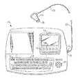
- FIG. 1is a plan view of a stand-alone embodiment of the spirometry apparatus of the present invention
- FIG. 2is a block diagram illustrating the spirometry apparatus of the present invention
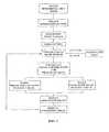
- FIG. 3is a block diagram illustrating the method of the present invention.
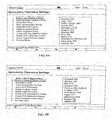
- FIG. 4shows a sample menu display of spirometry settings options
- FIG. 5shows a sample menu display of spirometry operation settings
- FIG. 6Ashows a sample menu display of available adult predictive norms
- FIG. 6Bshows a sample menu display of available pediatric predictive norms
- FIGS. 7A & 7Bshow a first set of paired animation images
- FIGS. 8A & 8Bshow a second set of paired animation images
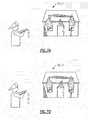
- FIGS. 9A & 9Bshow a third set of paired animation images
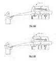
- FIGS. 10A & 10Bshow a fourth set of paired animation images
- FIGS. 11A & 11Bshow a fifth set of paired animation images
- FIGS. 12A & 12Bshow a sixth set of paired animation images
- FIGS. 13A & 13Bshow a seventh set of paired animation images
- FIGS. 14A & 14Bshow a eighth set of paired animation images
- FIGS. 15A & 15Bshow a ninth set of paired animation images
- FIG. 16is a flow chart illustrating the process for selection of the animation image to be displayed.
- a spirometry system in accordance with the present inventionis shown integrated in a patient evaluation workstation 10 .
- the workstation 10may include other patient evaluation systems, such as for example an electrocardiograph, which operate independently of the spirometry system of the present invention and are not pertinent to the discussion of the present invention.
- the workstation 10includes a display screen 12 with associated function buttons 15 , an alphanumeric keyboard 14 , an on/off switch 16 and a multi-direction arrow key pad 18 .
- the spirometry system of the present inventionis not limited in application to the depicted embodiment.
- the spirometry system of the present inventionmay also be embodied as a stand-alone patient evaluation device or associated with a personal computer, whether desk-top, or portable, or main frame computer network.
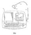
- the spirometry system 20includes an air-tube 22 , a flow measurement sensor 24 operatively connected to the air-tube 22 by flow tubing 23 , a display screen 26 , and an associated processor 30 .
- the air-tube 22may be of conventional design having a mouthpiece 25 adapted to be received into the mouth of the user for exhaling or inhaling air flow therethrough induced by the user.
- the flow measurement sensor 24is disposed at the distal end of the flow tubing 23 and connected to the processor 30 , for example to a RS-232 serial port 32 associated with the processor 30 .
- the flow measurement sensor 24may be provided with an appropriate transmitter and the processor 30 with a compatible receiver for providing wireless communication between the flow measurement sensor 24 and the processor 30 .
- Any type of flow measurement sensormaybe used that produces a signal proportional to the induced air flow through the air-tube 22 .
- the flow measurement sensormay comprise a fixed orifice device with pressure transducer and an associated analog-to-digital signal converter.
- the air-tube, pressure tubing assembly and flow sensor assemblymay comprise a Model D9w spirometer unit commercially available from Medikro OY of Kuopio, Finland, which is equipped with a Medikro model M9228 pressure transducer and Medikro Model M9220 flow tubing.
- the processor 30includes a system memory 40 including an image buffer 50 , and a control circuit 60 having conventional electronics for receiving various inputs, including measurement data from the sensor 24 , for processing air flow measurement data generated by the flow measurement sensor 24 , and controlling various outputs, including the displays presented to the user on the display screen 12 .
- the control circuit 60may include a controller and a central processing unit and is in communication with the system memory 40 .
- the system memory 40is adapted to receive and store pre-installed information, such as for example normative performance parameters from one or more clinical population studies, inputted information, such as demographics of the test subject and desired performance parameters, and test results for the test subject, both prior and concurrent.
- the system memory 40may include such as elements as RAM, EROM, EPROM and FLASH memory.
- the image buffer 50is adapted to store a plurality of pre-installed motivational animation images to be selectively display on the display screen 12 in a manner to be further described hereinafter.
- motivational animation imagesare selectively displayed on the display screen 12 in response to the real-time performance of the test subject using the spirometry apparatus 20 .
- the method of the present inventionincludes the steps of measuring a flow of air generated by a user during a period of use of the spirometry system, processing the measurements to determine a peak flow rate and a total flow volume, evaluating the determined peak flow rate relative to a normative value therefor, and evaluating the determined total flow volume relative to a normative value therefor; generating a motivational animation having a first aspect that reflects the relative evaluation of the determined peak flow rate to the normative value therefor and having a second aspect that reflects the relative evaluation of the determined total flow volume to the normative value therefor.
- the operatorselects “Spirometry Settings” from a main menu on the display screen 12 or otherwise elects to enter the spirometry test mode, for example by pressing the spirometer function button 1 5 B on the workstation 10 .
- the processor 30checks to verify that the spirometry flow measurement sensor 24 is indeed operatively connected to and in communication with the processor 30 . If not, the processor will display “No Spirometer Found”, thus prompting the operator to take corrective action. With the sensor 24 operative, the processor 30 will display a Spirometry Settings menu, such as illustrated in FIG. 4 , on the display screen 12 .
- the processor 30When the operator selects a particular option from the Spirometry Settings menu, the name of the option will appear on the status screen. For example, the operator will select the Spirometry Operation Settings to select the normative parameter that will be used for the upcoming test. In response thereto, the processor 30 will cause a display representing the available operational settings, such as for example as illustrated in FIG. 5 . The operator now has the option of selecting the particular normative reference that will be used in calculating the test subjects relative performance versus the selected normative reference. If the operator selects the Adult Predictive Norm option, the processor 30 will display a plurality of options on the display screen 12 , such as for example illustrated in FIG.
- each option identifying a particular clinical study accepted in the medical field as a valid adult normative studyone of which may be identified as a default option.
- the processor 30will display a plurality of options on the display screen 12 , such as for example illustrated in FIG. 6B , each option identifying a particular clinical study accepted in the medical field as a valid pediatric normative study, one of which may be identified as a default option.
- the studies identified in FIGS. 6A and 6Bare merely representative of available clinical studies and are illustrated solely for purposes of illustration.
- the operatormay instead select “Best Effort” from the Spirometry Operation Settings menu. If this option is selected, the performance of the test subject is measured against prior performance rather than a normative value from a clinical study.
- the processor 30will display two options for calculation of best effort: Best Measurement or Best Composite. If Best Measurement is selected, the performance of the test subject will be compared against the calculated total volume and the calculated peak flow rate from the best prior test for the test subject, the best test being the having the highest sum of total flow volume and peak flow rate values. If Best Composite is selected, the performance of the test subject will be compared against individual composite valves of all or the last so many tests preceding the upcoming test. For either option, the processor 30 will calculate the appropriate goal values using prior test data for the test subject, that prior data having been stored by the processor 30 is the data storage memory 40 .
- the operatormay also select the “Insert Composite Norm Values” to directly input a set of individual performance norms that the operator desires the test subject to achieve. This allows the attending medical staff to personalize the performance scaling to a particular test subject. For example, the operator may select particular normative references from various clinical studies, rather than selecting all from a single clinical study.
- the remaining options on the Spirometry Operation Settings menuare self-explanatory to those skilled in the art and are not germane to understanding the present invention.
- the processor 30When using clinical studies for selecting the predictive normative parameters, the processor 30 will use demographical information relating to the particular test subject, including for example but not limited to age, height, weight, sex, etc., to select the particular goal values for total volume flow and peak flow rate for the test subject based on the selected study installed in the data storage memory. If Best Efforts has been selected, the processor 30 will set the goal values equal to the test subjects best measurement or best composite values, as selected, as total volume flow and peak flow rate. If specific desired goals have been input for the test subject, the processor 30 will simply set the goal values for total volume flow and peak flow rate to the respective inputted values therefor. The goal values for total flow volume and peak flow rate having been established, the test subject may now initiate a test by exhaling into the air-tube as hard as and as long as the test subject is able.
- demographical information relating to the particular test subjectincluding for example but not limited to age, height, weight, sex, etc.
- the present inventionprovides a real-time motivational animation having two aspects, one of which varies in response to the scaled values for PEF and the other of which varies in response to the scaled values for FVC. Further, the motivational animation is adapted to encourage an increasing powerful blow and a sustained expiration.
- the initial goalsmay be scaled up or down after or while the clinician observes the test subject's performance and ability.
- the motivational animation displayed on display screen 12 during a testdepicts an animation of a fireman spraying water from a hose in the direction of a fire, in this embodiment a house fire.
- this animationwater is initially merely dripping from the hose held by the fireman, while a number of fires burn on the burning house.
- the goal of the animationis to extinguish all of the fires.
- the test subjectmust achieve the goal values for both peak flow rate and total volume flow determined as hereinbefore described for that particular test subject. The magnitude of and distance that the water flow extends to the house is directly related to achievement of the peak flow rate goal.
- the test subjectFor water from the hose to reach the fires, the test subject must achieve a peak flow rate equal to or greater than a preset percentage of goal value for peak flow rate. Once that preset percentage of the goal value for peak flow rate is achieved, the water flowing from the hose in the animation reaches the fires. The degree of the fire extinguished is directly related to achievement of the goal value for total volume expelled for the particular test subject once the water flow has reached the fire in the animation. When the test subject achieves a preset percentage of the goal value for the total volume, all fires on the animation are completely extinguished and a congratulatory message, such as “Good Job” is displayed across the screen display 12 .
- the various images 70 - 1 through 70 - 18are stored in digital format in the image buffer of the processor 30 .
- the imagesare stored in paired sets, each set of paired images shown in a separate one of FIGS. 7-15 .
- the processor 30determines which particular set of paired images is displayed in rapidly alternating fashion to form the animation displayed on the display screen 12 at any given time.
- Each paired set of imagescorresponds to a particular stage of attainment of the aforementioned goal values.
- the animation of water flow from the fireman's hosemay be subdivided into a number of stages of achievement based on the scaled peak flow rate calculation expressed as % Expected PEF, for example five states as specified in the following Table I.
- the animation of extinguishment of the firemay be subdivided into a number of states of achievement based on the scaled total volume flow calculation expressed as % Expected FVC, for example three stages as specified in Table II following.
- FIG. 16A block diagram illustrating the method of selecting the animation image is presented in FIG. 16 .
- the processor 30will display paired animation images 70 - 1 and 70 - 2 , shown in FIG. 7 , which represent water state 1 .
- paired animation images 70 - 1 and 70 - 2shown in FIG. 7 , which represent water state 1 .
- a moving animationis created.
- This animationwill continue to be displayed until the test subject achieves a scaled peak flow rate, % Expected PEF, of at least 20% of the goal value for PEF.
- the processor 30will change the animation image displayed to a new set of paired images based on the then current value of % Expected PEF.
- the processor 30When the test subject achieves a current % Expected PEF lying in water state 2 as defined in Table I, the processor 30 will display paired animation images 70 - 3 and 70 - 4 as shown in display paired animation images 70 - 7 and 70 - 8 as shown in FIG. 10 . Eventually, when the test subject achieves a current % Expected PEF lying in water state 5 as defined in Table I, the processor 30 will display paired animation images 70 - 9 and 70 - 10 as shown in FIG. 11 . At this point, the test subject will have exhaled hard enough to have reached at least 80% of the goal value for peak flow rate for that particular test subject and water from the hose will have finally reached the fire in the house.
- processor 30will now use the fire state in selecting the animation image to be displayed. If the test has achieved a current scaled total volume flow, that is % Expected FVC, of at least 40% of the goal value for FVC for that test subject, the processor 30 will change the animation image to either fire state 2 , fire state 1 or fire state 0 as appropriate. If the % Expected FVC corresponds to fire state 2 as defined in Table II, the processor 30 will display paired animation images 70 - 11 and 70 - 12 as shown in FIG. 12 .
- the processor 30will display paired animation images 70 - 13 and 70 - 14 as shown in FIG. 13 . If the % Expected FVC corresponds to fire state 0 as defined in Table II, the processor 30 will display paired animation images 70 - 15 and 70 - 16 as shown in FIG. 14 . Finally, the test subject has achieved both the peak flow rate goal and the total volume flow goal, the processor 30 will now display the final set of paired images 70 - 17 and 70 - 18 , as shown in FIG. 15 , with the congratulatory message “GOOD JOB”.
- the operator of the spirometry apparatusmay elect to display the achievement results of a test subject on a test in the conventional graphical format of FVC over time accompanied by a chart displaying the achieved values and the predicted values for various parameters including FVC and peak flow rate, as well as a percentage evaluation of the achieved value vis-à-vis its corresponding goal value.
- the teachings of the present inventionare not limited in application to the motivational animation of a fireman extinguishing a fire as depicted in the drawings. It is to be understood that the present invention may be practiced using other animations that include a first aspect that reflects a relative evaluation of a determined peak flow rate to a goal value therefor and a second aspect that reflects a relative evaluation of a determined total volume to a goal value therefor.
- the teachings of the present inventionmay also be applied to use of spirometry system for evaluating a patient's inhalation ability.
- the patient's peak inspiratory flow ratePPF
- PEFpeak expiratory flow rate
- the animation imageswould, in accord with the teachings of the present invention, include a first aspect that reflects a relative evaluation of a determined inspiratory peak flow rate to a goal value therefor and a second aspect that reflects a relative evaluation of a determined total flow volume to a goal value therefor.
Landscapes
- Health & Medical Sciences (AREA)
- Life Sciences & Earth Sciences (AREA)
- Pulmonology (AREA)
- Biomedical Technology (AREA)
- Medical Informatics (AREA)
- Biophysics (AREA)
- Pathology (AREA)
- Engineering & Computer Science (AREA)
- Physiology (AREA)
- Heart & Thoracic Surgery (AREA)
- Physics & Mathematics (AREA)
- Molecular Biology (AREA)
- Surgery (AREA)
- Animal Behavior & Ethology (AREA)
- General Health & Medical Sciences (AREA)
- Public Health (AREA)
- Veterinary Medicine (AREA)
- Measurement Of The Respiration, Hearing Ability, Form, And Blood Characteristics Of Living Organisms (AREA)
Abstract
Description
% ExpectedPEF=(CurrentPEFvalue/PEFGoal value)*100
% ExpectedFVC=(CurrentFVCvalue!FVCGoal value)*100.
| TABLE I | |||
| Animation of water flow | Percent of expected | ||
| Water State | |||
| 1 | 0-19 | ||
| Water State | |||
| 2 | 20-39 | ||
| Water State | |||
| 3 | 40-59 | ||
| Water State | |||
| 4 | 60-79 | ||
| Water State | |||
| 5 | >=80% | ||
| TABLE II | |||
| Animation of fire | Percent of expected | ||
| Fire State | |||
| 2 | 40-59 | ||
| First State | |||
| 1 | 60-79 | ||
| First State | |||
| 0 | >=80% | ||
| TABLE III | ||
| State | Animation Image | |
| Water State | ||
| 1 | 70-1, 70-2 | Water drips out of hose |
| Three Flames on | ||
| Water State | ||
| 2 | 70-3, 70-4 | First increased water flow |
| Three fames on | ||
| Water State | ||
| 3 | 70-5, 70-6 | Second increased water flow |
| Three flames on | ||
| Water State | ||
| 4 | 70-7, 70-8 | Third increased water flow |
| Three flames on | ||
| Water State | ||
| 5 | 7-9, 7-10 | Water hits all flames |
| Three flames on | ||
| Fire State | ||
| 2 | 7-11, 7-12 | Leftmost flame turns to smoke |
| Middle and rightmost flames are | ||
| still burning | ||
| 7-13, 7-14 | Middle flame turns to smoke | |
| Rightmost flame is still burning | ||
| 7-15, 7-16 | Rightmost flame turns to smoke | |
| All flames have been | ||
| extinguished | ||
| Animation continues in this state | ||
| until user input occurs | ||
| Success | 7-17, 7-18 | On user input, display “Good |
| Job!” message if patient reached | ||
Claims (14)
Priority Applications (1)
| Application Number | Priority Date | Filing Date | Title |
|---|---|---|---|
| US12/577,319US8398561B2 (en) | 2005-03-14 | 2009-10-12 | Motivational spirometry system and method |
Applications Claiming Priority (2)
| Application Number | Priority Date | Filing Date | Title |
|---|---|---|---|
| US11/079,714US7625345B2 (en) | 2005-03-14 | 2005-03-14 | Motivational spirometry system and method |
| US12/577,319US8398561B2 (en) | 2005-03-14 | 2009-10-12 | Motivational spirometry system and method |
Related Parent Applications (1)
| Application Number | Title | Priority Date | Filing Date |
|---|---|---|---|
| US11/079,714DivisionUS7625345B2 (en) | 2005-03-14 | 2005-03-14 | Motivational spirometry system and method |
Publications (2)
| Publication Number | Publication Date |
|---|---|
| US20100022905A1 US20100022905A1 (en) | 2010-01-28 |
| US8398561B2true US8398561B2 (en) | 2013-03-19 |
Family
ID=36972002
Family Applications (2)
| Application Number | Title | Priority Date | Filing Date |
|---|---|---|---|
| US11/079,714Active2025-12-23US7625345B2 (en) | 2005-03-14 | 2005-03-14 | Motivational spirometry system and method |
| US12/577,319Active2027-06-06US8398561B2 (en) | 2005-03-14 | 2009-10-12 | Motivational spirometry system and method |
Family Applications Before (1)
| Application Number | Title | Priority Date | Filing Date |
|---|---|---|---|
| US11/079,714Active2025-12-23US7625345B2 (en) | 2005-03-14 | 2005-03-14 | Motivational spirometry system and method |
Country Status (1)
| Country | Link |
|---|---|
| US (2) | US7625345B2 (en) |
Cited By (1)
| Publication number | Priority date | Publication date | Assignee | Title |
|---|---|---|---|---|
| US10810283B2 (en) | 2013-10-31 | 2020-10-20 | Knox Medical Diagnostics Inc. | Systems and methods for monitoring respiratory function |
Families Citing this family (32)
| Publication number | Priority date | Publication date | Assignee | Title |
|---|---|---|---|---|
| US5915379A (en) | 1997-03-14 | 1999-06-29 | Nellcor Puritan Bennett Incorporated | Graphic user interface for a patient ventilator |
| WO2006138274A2 (en)* | 2005-06-13 | 2006-12-28 | The University Of Vermont And State Agricultural College | Breath biofeedback system and method |
| JP2007190278A (en)* | 2006-01-20 | 2007-08-02 | Omron Healthcare Co Ltd | Breathing exerciser |
| JP2007190277A (en)* | 2006-01-20 | 2007-08-02 | Omron Healthcare Co Ltd | Breathing exerciser and breathing training program |
| US8021310B2 (en) | 2006-04-21 | 2011-09-20 | Nellcor Puritan Bennett Llc | Work of breathing display for a ventilation system |
| US20090184968A1 (en)* | 2006-04-26 | 2009-07-23 | Mir Srl Medical International Research | Incentive Method For The Spirometry Test With Universal Control System Regardless Of Any Chosen Stimulating Image |
| US7784461B2 (en) | 2006-09-26 | 2010-08-31 | Nellcor Puritan Bennett Llc | Three-dimensional waveform display for a breathing assistance system |
| US8272378B2 (en)* | 2008-04-16 | 2012-09-25 | Eumedics Medlzintechnik Und Marketing Gmbh | System and method for improving endurance of inspiratory muscles |
| EP2375977B1 (en)* | 2009-01-14 | 2014-12-24 | St. Michael's Hospital | Detection of dynamic hyperinflation in spontaneously breathing mechanically ventilated patients |
| US20110021940A1 (en)* | 2009-07-21 | 2011-01-27 | Edmond Chu | Incentive audio for pulmonary function diagnostics |
| US9138167B1 (en)* | 2009-09-25 | 2015-09-22 | Krispin Johan Leydon | Means for rendering key respiratory measurements accessible to mobile digital devices |
| US10869638B2 (en) | 2009-09-25 | 2020-12-22 | Krispin Johan Leydon | Systems, devices and methods for rendering key respiratory measurements accessible to mobile digital devices |
| US9119925B2 (en) | 2009-12-04 | 2015-09-01 | Covidien Lp | Quick initiation of respiratory support via a ventilator user interface |
| US8335992B2 (en) | 2009-12-04 | 2012-12-18 | Nellcor Puritan Bennett Llc | Visual indication of settings changes on a ventilator graphical user interface |
| US8924878B2 (en) | 2009-12-04 | 2014-12-30 | Covidien Lp | Display and access to settings on a ventilator graphical user interface |
| US9262588B2 (en) | 2009-12-18 | 2016-02-16 | Covidien Lp | Display of respiratory data graphs on a ventilator graphical user interface |
| US8499252B2 (en) | 2009-12-18 | 2013-07-30 | Covidien Lp | Display of respiratory data graphs on a ventilator graphical user interface |
| US20120029376A1 (en)* | 2010-07-28 | 2012-02-02 | Pmd Healthcare | Personal Spirometer |
| US20130066225A1 (en)* | 2011-09-08 | 2013-03-14 | Kourosh Kojouri | Monitoring incentive spirometry |
| DE102012200815B3 (en)* | 2012-01-20 | 2013-01-10 | Dieter Kirsch | An inhalation support device and method for inhalation support |
| US10362967B2 (en) | 2012-07-09 | 2019-07-30 | Covidien Lp | Systems and methods for missed breath detection and indication |
| US10350375B2 (en)* | 2013-07-03 | 2019-07-16 | Astartein, Llc | Devices, systems and methods for facilitating facemask compliance |
| US20150223750A1 (en)* | 2014-02-12 | 2015-08-13 | Wipro Limited | Method for improving breathing performance of a user and an electronic device therefor |
| US9950129B2 (en) | 2014-10-27 | 2018-04-24 | Covidien Lp | Ventilation triggering using change-point detection |
| WO2016072948A1 (en)* | 2014-11-04 | 2016-05-12 | OZTURK Merthan | A spirometer with feedback unit and a control method thereof |
| WO2016161036A1 (en) | 2015-04-01 | 2016-10-06 | Compliant Games, Inc. | Respiratory therapy instrument offering game-based incentives,training, and telemetry collection |
| KR101765423B1 (en)* | 2016-11-18 | 2017-08-07 | 경희대학교 산학협력단 | Method and apparatus for pulmonary function test |
| CN108523895B (en)* | 2018-03-23 | 2024-08-02 | 康泰医学系统(秦皇岛)股份有限公司 | Expiration duration indicating device for spirometer |
| CN108888282A (en)* | 2018-04-25 | 2018-11-27 | 杭州聚陆医疗器械有限公司 | A kind of intelligent respiratory muscle function assessment feedback training system and its application method |
| US12053272B2 (en) | 2018-10-30 | 2024-08-06 | Tidal Medical Technologies Llc | Systems and methods for monitoring of incentive spirometry |
| US10610129B1 (en)* | 2018-10-30 | 2020-04-07 | Foad Farahmand Md Pllc | Systems and methods for portable monitoring of incentive spirometry |
| US11672934B2 (en) | 2020-05-12 | 2023-06-13 | Covidien Lp | Remote ventilator adjustment |
Citations (18)
| Publication number | Priority date | Publication date | Assignee | Title |
|---|---|---|---|---|
| US3896792A (en) | 1974-05-15 | 1975-07-29 | Us Navy | Real-time cyclic pulmonary function test system |
| US4296756A (en) | 1979-07-26 | 1981-10-27 | Cyber Diagnostics, Inc. | Remote pulmonary function tester |
| US4984158A (en) | 1988-10-14 | 1991-01-08 | Hillsman Dean | Metered dose inhaler biofeedback training and evaluation system |
| US5137026A (en) | 1990-01-04 | 1992-08-11 | Glaxo Australia Pty., Ltd. | Personal spirometer |
| US5167506A (en) | 1991-10-24 | 1992-12-01 | Minnesota Mining And Manufacturing Company | Inhalation device training system |
| US5267942A (en) | 1992-04-20 | 1993-12-07 | Utah State University Foundation | Method for influencing physiological processes through physiologically interactive stimuli |
| US5318038A (en) | 1993-01-19 | 1994-06-07 | Trustees Of Boston University | Infant respiratory impedance measuring apparatus and methods using forced oscillations |
| US5333106A (en) | 1992-10-09 | 1994-07-26 | Circadian, Inc. | Apparatus and visual display method for training in the power use of aerosol pharmaceutical inhalers |
| US5431154A (en) | 1991-11-29 | 1995-07-11 | Seigel; David | Incentive metered dose inhaler |
| US5549117A (en) | 1994-05-23 | 1996-08-27 | Enact Health Management Systems | System for monitoring and reporting medical measurements |
| US5564432A (en) | 1994-07-13 | 1996-10-15 | Thomson; Ronald A. | Biodegradable air tube and spirometer employing same |
| US5827179A (en) | 1997-02-28 | 1998-10-27 | Qrs Diagnostic, Llc | Personal computer card for collection for real-time biological data |
| US6083141A (en) | 1995-02-10 | 2000-07-04 | Hougen; Everett D. | Portable respiratory exercise apparatus and method for using the same |
| US6167362A (en) | 1997-01-10 | 2000-12-26 | Health Hero Network, Inc. | Motivational tool for adherence to medical regimen |
| US20010003144A1 (en) | 1998-06-15 | 2001-06-07 | Daphna Vilozni | Spirometry test and analysis system |
| US6468211B1 (en) | 1999-05-28 | 2002-10-22 | Orca Diagnostics Corporation | Cardiopulmonary exercise testing apparatus and method |
| US20030000522A1 (en) | 2001-05-17 | 2003-01-02 | Lynn Lawrence A. | Centralized hospital monitoring system for automatically detecting upper airway instability and for preventing and aborting adverse drug reactions |
| US20030216660A1 (en)* | 1999-06-08 | 2003-11-20 | Ilan Ben-Oren | Breath test apparatus and methods |
- 2005
- 2005-03-14USUS11/079,714patent/US7625345B2/enactiveActive
- 2009
- 2009-10-12USUS12/577,319patent/US8398561B2/enactiveActive
Patent Citations (19)
| Publication number | Priority date | Publication date | Assignee | Title |
|---|---|---|---|---|
| US3896792A (en) | 1974-05-15 | 1975-07-29 | Us Navy | Real-time cyclic pulmonary function test system |
| US4296756A (en) | 1979-07-26 | 1981-10-27 | Cyber Diagnostics, Inc. | Remote pulmonary function tester |
| US4984158A (en) | 1988-10-14 | 1991-01-08 | Hillsman Dean | Metered dose inhaler biofeedback training and evaluation system |
| US5137026A (en) | 1990-01-04 | 1992-08-11 | Glaxo Australia Pty., Ltd. | Personal spirometer |
| US5167506A (en) | 1991-10-24 | 1992-12-01 | Minnesota Mining And Manufacturing Company | Inhalation device training system |
| US5431154A (en) | 1991-11-29 | 1995-07-11 | Seigel; David | Incentive metered dose inhaler |
| US5267942A (en) | 1992-04-20 | 1993-12-07 | Utah State University Foundation | Method for influencing physiological processes through physiologically interactive stimuli |
| US5333106A (en) | 1992-10-09 | 1994-07-26 | Circadian, Inc. | Apparatus and visual display method for training in the power use of aerosol pharmaceutical inhalers |
| US5318038A (en) | 1993-01-19 | 1994-06-07 | Trustees Of Boston University | Infant respiratory impedance measuring apparatus and methods using forced oscillations |
| US5549117A (en) | 1994-05-23 | 1996-08-27 | Enact Health Management Systems | System for monitoring and reporting medical measurements |
| US5564432A (en) | 1994-07-13 | 1996-10-15 | Thomson; Ronald A. | Biodegradable air tube and spirometer employing same |
| US6083141A (en) | 1995-02-10 | 2000-07-04 | Hougen; Everett D. | Portable respiratory exercise apparatus and method for using the same |
| US6167362A (en) | 1997-01-10 | 2000-12-26 | Health Hero Network, Inc. | Motivational tool for adherence to medical regimen |
| US5827179A (en) | 1997-02-28 | 1998-10-27 | Qrs Diagnostic, Llc | Personal computer card for collection for real-time biological data |
| US20010003144A1 (en) | 1998-06-15 | 2001-06-07 | Daphna Vilozni | Spirometry test and analysis system |
| US6508772B2 (en) | 1998-06-15 | 2003-01-21 | Daphna Vilozni | Spirometry test and analysis system |
| US6468211B1 (en) | 1999-05-28 | 2002-10-22 | Orca Diagnostics Corporation | Cardiopulmonary exercise testing apparatus and method |
| US20030216660A1 (en)* | 1999-06-08 | 2003-11-20 | Ilan Ben-Oren | Breath test apparatus and methods |
| US20030000522A1 (en) | 2001-05-17 | 2003-01-02 | Lynn Lawrence A. | Centralized hospital monitoring system for automatically detecting upper airway instability and for preventing and aborting adverse drug reactions |
Non-Patent Citations (8)
| Title |
|---|
| Micro Medical Ltd; "Spida 5"; Product brochure; printed from www.micromedical.co.uk on Feb. 1, 2005. |
| Micro-Direct; "Spida 5"; printed from www.micro-direct.com/spida.html on Feb. 15, 2005. |
| Micro-Direct; "Spiro USB Spirometer"; printed from www.micro-dinact.com/spiro USB.html on Feb. 1, 2005. |
| Micro-Direct; "The New NicroLab 3500 Spirometer"; printed from www.micro-direct.com/microlab.html on Feb. 1, 2005. |
| Numed; "Microloop Spirmeter"; printed from www.numed.co.uk/microloop.html on Feb. 1, 2005. |
| The Nagel Network, Inc; "PC Based Spirometers"; printed from www.nagelnetwork.com/pcspir.html on Feb. 1, 2005. |
| Welch Allyn, Inc.; Spirometer Product Brochure, copyright 2003. |
| Yemenijian, Debra; "2004 Spirometry Buyers Guide". |
Cited By (1)
| Publication number | Priority date | Publication date | Assignee | Title |
|---|---|---|---|---|
| US10810283B2 (en) | 2013-10-31 | 2020-10-20 | Knox Medical Diagnostics Inc. | Systems and methods for monitoring respiratory function |
Also Published As
| Publication number | Publication date |
|---|---|
| US7625345B2 (en) | 2009-12-01 |
| US20060206036A1 (en) | 2006-09-14 |
| US20100022905A1 (en) | 2010-01-28 |
Similar Documents
| Publication | Publication Date | Title |
|---|---|---|
| US8398561B2 (en) | Motivational spirometry system and method | |
| US11351418B2 (en) | Breathing training, monitoring and/or assistance device | |
| US8696592B2 (en) | Breath biofeedback system and method | |
| US8272378B2 (en) | System and method for improving endurance of inspiratory muscles | |
| US8757152B2 (en) | Ventilator-initiated prompt regarding detection of double triggering during a volume-control breath type | |
| KR101884360B1 (en) | Portable respiration training device system and thereof methods | |
| JP5028424B2 (en) | Method and apparatus for simplifying diagnostic evaluation of mechanically ventilated patients | |
| US8757153B2 (en) | Ventilator-initiated prompt regarding detection of double triggering during ventilation | |
| JP5592483B2 (en) | Ventilator and adjustment method thereof | |
| US10350374B2 (en) | Ventilator system and method | |
| US20120216809A1 (en) | Ventilator-Initiated Prompt Regarding Detection Of Inadequate Flow During Ventilation | |
| US20110282228A1 (en) | Methods and Devices for Determining Pulmonary Measurements | |
| US20190134460A1 (en) | Respiratory therapy device and system with integrated gaming capabilities and method of using the same | |
| KR102326251B1 (en) | Smart Lung-Capacity Training System | |
| CN101574259B (en) | Measuring system and method for operating the measuring system | |
| JP6948643B2 (en) | Pulmonary function test device | |
| US20220160255A1 (en) | Device, process and computer program for influencing the breathing of a person | |
| JPH08164225A (en) | Trainer for respiratory organs | |
| JP2007229101A (en) | Respiratory function testing device | |
| US20190192795A1 (en) | Expiratory flow limitation detection via flow resistor adjustment | |
| KR20210051661A (en) | Smart breathing system based on energy havesting | |
| WO2017047595A1 (en) | Breathing state display device, breathing state display method, and breathing state display program | |
| KR102400487B1 (en) | Portable spirometer system with game for rehabilitation of respiratory muscles and its driving method | |
| CN116966508A (en) | A respiratory-driven pulmonary rehabilitation exercise and its effect monitoring system | |
| RU91765U1 (en) | BIOLOGICAL FEEDBACK RESPIRATORY SIMULATOR |
Legal Events
| Date | Code | Title | Description |
|---|---|---|---|
| AS | Assignment | Owner name:WELCH ALLYN, INC., NEW YORK Free format text:ASSIGNMENT OF ASSIGNORS INTEREST;ASSIGNOR:QUINN, DAVID EDWARD;REEL/FRAME:023357/0283 Effective date:20050309 | |
| STCF | Information on status: patent grant | Free format text:PATENTED CASE | |
| AS | Assignment | Owner name:JPMORGAN CHASE BANK, N.A., AS COLLATERAL AGENT, ILLINOIS Free format text:SECURITY INTEREST;ASSIGNORS:ALLEN MEDICAL SYSTEMS, INC.;HILL-ROM SERVICES, INC.;ASPEN SURGICAL PRODUCTS, INC.;AND OTHERS;REEL/FRAME:036582/0123 Effective date:20150908 Owner name:JPMORGAN CHASE BANK, N.A., AS COLLATERAL AGENT, IL Free format text:SECURITY INTEREST;ASSIGNORS:ALLEN MEDICAL SYSTEMS, INC.;HILL-ROM SERVICES, INC.;ASPEN SURGICAL PRODUCTS, INC.;AND OTHERS;REEL/FRAME:036582/0123 Effective date:20150908 | |
| FPAY | Fee payment | Year of fee payment:4 | |
| AS | Assignment | Owner name:JPMORGAN CHASE BANK, N.A., AS COLLATERAL AGENT, ILLINOIS Free format text:SECURITY AGREEMENT;ASSIGNORS:HILL-ROM SERVICES, INC.;ASPEN SURGICAL PRODUCTS, INC.;ALLEN MEDICAL SYSTEMS, INC.;AND OTHERS;REEL/FRAME:040145/0445 Effective date:20160921 Owner name:JPMORGAN CHASE BANK, N.A., AS COLLATERAL AGENT, IL Free format text:SECURITY AGREEMENT;ASSIGNORS:HILL-ROM SERVICES, INC.;ASPEN SURGICAL PRODUCTS, INC.;ALLEN MEDICAL SYSTEMS, INC.;AND OTHERS;REEL/FRAME:040145/0445 Effective date:20160921 | |
| AS | Assignment | Owner name:ALLEN MEDICAL SYSTEMS, INC., ILLINOIS Free format text:RELEASE BY SECURED PARTY;ASSIGNOR:JPMORGAN CHASE BANK, N.A.;REEL/FRAME:050254/0513 Effective date:20190830 Owner name:MORTARA INSTRUMENT, INC., WISCONSIN Free format text:RELEASE BY SECURED PARTY;ASSIGNOR:JPMORGAN CHASE BANK, N.A.;REEL/FRAME:050254/0513 Effective date:20190830 Owner name:MORTARA INSTRUMENT SERVICES, INC., WISCONSIN Free format text:RELEASE BY SECURED PARTY;ASSIGNOR:JPMORGAN CHASE BANK, N.A.;REEL/FRAME:050254/0513 Effective date:20190830 Owner name:VOALTE, INC., FLORIDA Free format text:RELEASE BY SECURED PARTY;ASSIGNOR:JPMORGAN CHASE BANK, N.A.;REEL/FRAME:050254/0513 Effective date:20190830 Owner name:HILL-ROM, INC., ILLINOIS Free format text:RELEASE BY SECURED PARTY;ASSIGNOR:JPMORGAN CHASE BANK, N.A.;REEL/FRAME:050254/0513 Effective date:20190830 Owner name:WELCH ALLYN, INC., NEW YORK Free format text:RELEASE BY SECURED PARTY;ASSIGNOR:JPMORGAN CHASE BANK, N.A.;REEL/FRAME:050254/0513 Effective date:20190830 Owner name:ANODYNE MEDICAL DEVICE, INC., FLORIDA Free format text:RELEASE BY SECURED PARTY;ASSIGNOR:JPMORGAN CHASE BANK, N.A.;REEL/FRAME:050254/0513 Effective date:20190830 Owner name:HILL-ROM SERVICES, INC., ILLINOIS Free format text:RELEASE BY SECURED PARTY;ASSIGNOR:JPMORGAN CHASE BANK, N.A.;REEL/FRAME:050254/0513 Effective date:20190830 Owner name:HILL-ROM COMPANY, INC., ILLINOIS Free format text:RELEASE BY SECURED PARTY;ASSIGNOR:JPMORGAN CHASE BANK, N.A.;REEL/FRAME:050254/0513 Effective date:20190830 | |
| AS | Assignment | Owner name:JPMORGAN CHASE BANK, N.A., ILLINOIS Free format text:SECURITY AGREEMENT;ASSIGNORS:HILL-ROM HOLDINGS, INC.;HILL-ROM, INC.;HILL-ROM SERVICES, INC.;AND OTHERS;REEL/FRAME:050260/0644 Effective date:20190830 | |
| MAFP | Maintenance fee payment | Free format text:PAYMENT OF MAINTENANCE FEE, 8TH YEAR, LARGE ENTITY (ORIGINAL EVENT CODE: M1552); ENTITY STATUS OF PATENT OWNER: LARGE ENTITY Year of fee payment:8 | |
| AS | Assignment | Owner name:HILL-ROM HOLDINGS, INC., ILLINOIS Free format text:RELEASE OF SECURITY INTEREST AT REEL/FRAME 050260/0644;ASSIGNOR:JPMORGAN CHASE BANK, N.A.;REEL/FRAME:058517/0001 Effective date:20211213 Owner name:BARDY DIAGNOSTICS, INC., ILLINOIS Free format text:RELEASE OF SECURITY INTEREST AT REEL/FRAME 050260/0644;ASSIGNOR:JPMORGAN CHASE BANK, N.A.;REEL/FRAME:058517/0001 Effective date:20211213 Owner name:VOALTE, INC., FLORIDA Free format text:RELEASE OF SECURITY INTEREST AT REEL/FRAME 050260/0644;ASSIGNOR:JPMORGAN CHASE BANK, N.A.;REEL/FRAME:058517/0001 Effective date:20211213 Owner name:HILL-ROM, INC., ILLINOIS Free format text:RELEASE OF SECURITY INTEREST AT REEL/FRAME 050260/0644;ASSIGNOR:JPMORGAN CHASE BANK, N.A.;REEL/FRAME:058517/0001 Effective date:20211213 Owner name:WELCH ALLYN, INC., NEW YORK Free format text:RELEASE OF SECURITY INTEREST AT REEL/FRAME 050260/0644;ASSIGNOR:JPMORGAN CHASE BANK, N.A.;REEL/FRAME:058517/0001 Effective date:20211213 Owner name:ALLEN MEDICAL SYSTEMS, INC., ILLINOIS Free format text:RELEASE OF SECURITY INTEREST AT REEL/FRAME 050260/0644;ASSIGNOR:JPMORGAN CHASE BANK, N.A.;REEL/FRAME:058517/0001 Effective date:20211213 Owner name:HILL-ROM SERVICES, INC., ILLINOIS Free format text:RELEASE OF SECURITY INTEREST AT REEL/FRAME 050260/0644;ASSIGNOR:JPMORGAN CHASE BANK, N.A.;REEL/FRAME:058517/0001 Effective date:20211213 Owner name:BREATHE TECHNOLOGIES, INC., CALIFORNIA Free format text:RELEASE OF SECURITY INTEREST AT REEL/FRAME 050260/0644;ASSIGNOR:JPMORGAN CHASE BANK, N.A.;REEL/FRAME:058517/0001 Effective date:20211213 | |
| MAFP | Maintenance fee payment | Free format text:PAYMENT OF MAINTENANCE FEE, 12TH YEAR, LARGE ENTITY (ORIGINAL EVENT CODE: M1553); ENTITY STATUS OF PATENT OWNER: LARGE ENTITY Year of fee payment:12 |