US8397948B2 - Dispensing device for edible goods and/or novelties - Google Patents
Dispensing device for edible goods and/or noveltiesDownload PDFInfo
- Publication number
- US8397948B2 US8397948B2US12/844,981US84498110AUS8397948B2US 8397948 B2US8397948 B2US 8397948B2US 84498110 AUS84498110 AUS 84498110AUS 8397948 B2US8397948 B2US 8397948B2
- Authority
- US
- United States
- Prior art keywords
- main body
- dispensing device
- dispensing
- sensor
- funnel
- Prior art date
- Legal status (The legal status is an assumption and is not a legal conclusion. Google has not performed a legal analysis and makes no representation as to the accuracy of the status listed.)
- Expired - Fee Related, expires
Links
Images


Classifications
- G—PHYSICS
- G01—MEASURING; TESTING
- G01F—MEASURING VOLUME, VOLUME FLOW, MASS FLOW OR LIQUID LEVEL; METERING BY VOLUME
- G01F13/00—Apparatus for measuring by volume and delivering fluids or fluent solid materials, not provided for in the preceding groups
- G01F13/001—Apparatus for measuring by volume and delivering fluids or fluent solid materials, not provided for in the preceding groups for fluent solid material
- G01F13/005—Apparatus for measuring by volume and delivering fluids or fluent solid materials, not provided for in the preceding groups for fluent solid material comprising a screw conveyor
- B—PERFORMING OPERATIONS; TRANSPORTING
- B65—CONVEYING; PACKING; STORING; HANDLING THIN OR FILAMENTARY MATERIAL
- B65D—CONTAINERS FOR STORAGE OR TRANSPORT OF ARTICLES OR MATERIALS, e.g. BAGS, BARRELS, BOTTLES, BOXES, CANS, CARTONS, CRATES, DRUMS, JARS, TANKS, HOPPERS, FORWARDING CONTAINERS; ACCESSORIES, CLOSURES, OR FITTINGS THEREFOR; PACKAGING ELEMENTS; PACKAGES
- B65D83/00—Containers or packages with special means for dispensing contents
- B65D83/775—Containers comprising an internal rotating wing for expelling the contents
Definitions
- the present inventionrelates to a dispensing device and more particularly, to an automated dispenser for edible goods and/or novelties.
- Dispensersare often used to dispense various solid items, including edible goods, ice, coffee, pharmaceuticals or small toys. Dispensers may provide control in terms of the amount of a particular good dispensed or how or when the item is dispensed. In addition, dispensers may provide a relatively sanitary alternative to the candy dish commonly seen on a desk or a bucket of ice placed on a countertop. However, room for improvement and further development remains. For example, many dispensers may include a slide or an enclosed volume that may become jammed if items get caught during dispensing. In other examples, many dispensers, particularly candy dispensers, may be activated by touching the dispenser, spreading germs.
- FIG. 1illustrates a front perspective view of an embodiment of the dispensing device contemplated herein.
- FIG. 2illustrates an exploded, side cross-sectional view of an embodiment of a tank and lid.
- FIG. 3illustrates a perspective cross-sectional view of an embodiment of a lid.
- FIG. 4illustrates a back perspective view of an embodiment of a tank.
- FIG. 5illustrates a side cross-sectional view of an embodiment of an upper portion of the dispensing device.
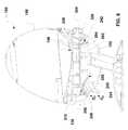
- FIG. 6illustrates a side cross-sectional view of an embodiment of a dispensing device.
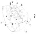
- FIG. 7illustrates a cross-sectional perspective view of an embodiment of a main body, inner cover and conveyance tube with an auger positioned therein.
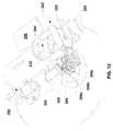
- FIG. 8illustrates a top, perspective view of an embodiment of a main body.
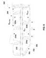
- FIG. 9illustrates a side, cross-sectional view of an embodiment of a conveyance tube with an auger therein.
- FIG. 10illustrates a side view of an embodiment of an auger.
- FIG. 11illustrates a side cross-sectional view of an embodiment of a dispensing device.
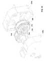
- FIG. 12illustrates a back/top perspective view of an embodiment of a conveyance tube, a drive motor mechanically coupled to the auger positioned within the conveyance tube, and a variable resistor with a dial.
- FIG. 13illustrates an exploded perspective view of an embodiment of a gear and clutch assembly.
- FIG. 14illustrates a close up view of the gear and clutch assembly of FIG. 13 .
- FIG. 15illustrates a bottom perspective view of an embodiment of the dispensing device with the main body removed from the figure illustrating the drive motor gear box.
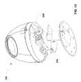
- FIG. 16illustrates a front view of an embodiment of the dispensing device with the storage portion, inner cover and main body removed, illustrating the sensor and a receptacle.
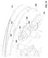
- FIG. 17illustrates a side perspective view of an embodiment of the dispensing device with the tank, lid and main body removed, illustrating the sensor.
- FIG. 18illustrates a bottom perspective view of an embodiment of the dispensing device with the tank, lid and main body removed, illustrating the vibratory device.
- FIG. 19illustrates a bottom perspective view of an embodiment of the dispensing device with the tank, lid and main body removed, illustrating the vibratory device.
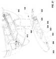
- FIG. 20illustrates an exploded side view of an embodiment of the stand.
- FIG. 21illustrates a side perspective cross-sectional view of an embodiment of the dispensing device illustrating the main body and the stand.
- FIG. 22illustrates a side view of an embodiment of the stand.
- FIG. 23illustrates a top perspective view of an embodiment of the stand.
- FIG. 24illustrates a bottom perspective of an embodiment of the stand.
- a dispensing devicein general, enables dispensing of goods or items within the device by activation of a sensor that may trigger the metering of goods or items from a storage tank.
- Goodsmay include, for example, candy, gum, other food stuffs or novelty such as various trinkets, toys, etc., as well as office goods, including paper clips, binder clips, tacks, etc.
- the dispensing devicemay include a main body, a stand supporting the main body, a tank mounted on the main body, a funnel within the tank and a lid for providing access to the interior of the tank.
- the dispensing devicemay also include a vibratory mechanism to prevent jamming of the items within the device when the items are dispensed.
- the vibratory mechanismmay also reduce sticking or agglomerating of items in the storage tank, such as when, for example, food items are in the tank and begin to melt or fuse together.
- an embodiment of a dispenser 100may generally include main body 102 , a stand 104 supporting the main body 102 , a storage portion 106 retained by the main body 102 , and a conveyance path providing communication between the main body and the storage portion for conveying items to be dispensed. While the dispenser 100 , as illustrated, takes the form of a generally egg-like shape, it is contemplated that other shapes may be provided as well.
- the devicemay take the form of, for example, other geometric figures or objects including animals, planes, trains, automobiles, food items, building blocks, etc.
- the dispensing devicemay include a tank 108 , which in association with the funnel 110 , may hold items to be dispensed.
- the tank 108may be formed from a relatively clear or transparent material, i.e., a material that may allow for the transmission of incident light in the visible range of 380 nm to 750 nm, including all values and increments therein.
- the tank 108may exhibit some degree of translucency, i.e., scattering of incident light.
- the materialneeds not be clear and may be, in some non-exclusive embodiments, opaque.
- Materials for fabricating the tankmay include, polycarbonate, acrylic, glass, metal, metal alloys, polypropylene, polyethylene, etc.
- the tankmay include a fill opening 112 defined therein at a first end 114 of the tank 108 .
- the fill opening 112may accommodate the lid 118 .
- the lid 118may be retained within the fill opening 112 by mechanically interlocking with an interior surface 120 defining the fill opening 112 .
- mating threadsmay be provided on both the lid rim 122 and the interior surface 120 of the opening 112 .
- frictional contactmay be made between the lid rim 122 and the interior surface 120 of the fill opening 112 .
- a gasket 123may be provided at the lid rim 122 or integrated into the lid rim 122 formed of a thermoplastic elastomer or a natural or synthetic rubber as illustrated in FIG. 3 .
- a depression 124illustrated in FIGS. 3 and 4 ) may be formed in the exterior surface 126 of the tank 108 allowing for a person to push against a surface 128 of the lid 118 (see FIG. 3 ) in a direction away from the fill opening 112 of the tank 108 .
- the tank 108may also include a second opening 130 defined by the bottom rim 132 of the tank 108 .
- the bottom rim 132 of the tankmay mate with the main body 102 as illustrated in FIG. 5 , such that a portion of the bottom rim 132 may be received and/or retained by the main body 102 .
- the main body 102may include one or more ledges 136 a , 136 b , etc. (hereinafter referred to as a ledge 136 ) defined in the main body 102 or extending from the main body wall 138 upon which the bottom rim 132 of the tank 108 may rest.
- the ledge 136need not surround the entirety of the main body 102 but may be defined by one or more protrusions 140 a , 140 b , etc. which extend from the main body wall 138 on the interior portion of the main body 102 .
- the bottom rim 132 and the main body 102may mechanically interlock. For example, mating threads may be provided on both the bottom rim 132 and the main body 102 . In other examples, the bottom rim 132 may be frictionally retained in the main body 102 .
- the tank 108may be affixed to the main body 102 such as by adhesives or welding of the tank 108 to the main body 102 .
- the funnel 110may include a first peripheral wall 150 and a second interior wall 152 , which may function to retain items to be dispensed within the tank 108 .
- the first peripheral wall 150 and second peripheral wall 152may define angle alpha ( ⁇ ) near the top of the funnel 154 , which may be in the range of 0 degrees to less than 90 degrees, including all values and increments therein such as from 0.1 to 89.9 degrees, 10 degrees, 30 degrees, etc.
- angle ( ⁇ )may vary around the funnel 110 , such that one side of the funnel 110 may exhibit a first angle ( ⁇ 1 ) and another portion of the funnel 110 may exhibit a second angle ( ⁇ 2 ).
- angle ( ⁇ )may vary continuously around the funnel 110 .
- the funnel 110may include a funnel opening 156 defined near the bottom of the funnel 158 through which items may pass into the conveyance tube 202 (discussed further below) near the first end 242 of the conveyance tube.
- the funnel 110may be formed of a number of materials, including metal or metal alloys, wood, glass, polymer materials including thermoplastics such as polypropylene, polyethylene, polycarbonate, acrylonitrile-butadiene-styrene, acrylic, and combinations thereof.
- the funnel 110may also rest on the ledge 136 defined by the main body 102 . As illustrated in FIG. 5 , the funnel 110 may rest interior of the bottom rim 132 of the tank 108 on the ledge 136 . However, it may be appreciated that, in some non-exclusive embodiments, the bottom rim 132 of the tank 108 may rest on the funnel 110 , which in turn may rest on the ledge 136 defined by the main body 102 . Further, the bottom rim 132 of the tank 108 may mechanically interlock with both the main body 102 and the funnel 110 , such as through mating threads or frictional retention.
- the bottom rim 132 of the tank 108 , the funnel 110 and the main body 102may be adhesively joined together or welding together, such as by ultrasonic welding.
- the tank 108may include a locating tab 160 and the main body 102 may include a notch 162 for receiving the locating tab 160 .
- the locating tab 160 and the main body 102may define a locating path 164 through which a mechanical fastener 166 , such as a thumbscrew, slotted screw or pin may pass.
- the peripheral wall 150 of the funnel 110may also define a portion of the locating path to retain the tank 108 and funnel 110 with relation to the main body 102 .
- the mechanical fastener 166may be removable or the mechanical fastener 166 may be locked in place, such as by ultrasonic welding, preventing access to the interior of the main body 102 through the tank 108 .
- FIGS. 6 through 11illustrates a conveyance path C p , which may be defined, at least in part by a conveyance tube 202 , including a conveyor, such as an auger 204 , positioned therein for transporting the items stored in the tank 108 to a dispensing mouth 206 defined in the wall 138 of the main body 102 .
- the conveyance tube 202may be mounted within or at least partially within the main body 102 in an inner cover 208 as illustrated further in FIG. 7 .
- the inner cover 208may include a conveyance tube recess 210 for accommodating the conveyance tube 202 .
- the inner cover 208may include one or more detents 212 a , 212 b , 212 c , etc.
- detents 212therein for aligning the inner cover 208 within the main body 102 , which may include one or more protrusions 140 as noted above. While the detents 212 and corresponding protrusions 140 may generally exhibit a rectangular cross-section, other shapes are contemplated, such as half-circles or triangles.
- the inner cover 208may mount on one or more bosses 214 a , 214 b (hereinafter bosses 214 ) provided in the main body 102 , an example of which are illustrated in FIG. 8 . Referring again to FIG.
- the inner cover 208may, in some non-exclusive embodiments, translate in the main body 102 , or may be displace-able in a vertical manner with respect to the main body 102 . In addition, the inner cover 208 may be completely removed from the main body 102 .
- the main body 102 and the inner cover 208may be formed of a metal, metal alloy, glass, wood, plastic including thermoplastic such as polypropylene, acrylic, polyethylene, acrylonitrile-butadiene-styrene, etc. It may be appreciated that the main body 102 and the inner cover 208 may be formed of the same or different materials.
- the inner cover 208may be removed to provide access into the interior portion 220 (see again FIG. 8 ) of the main body 102 , a panel or door may be provided in the side of the main body 102 in addition to, or instead of the inner cover 208 . Furthermore, where the interior portion 220 of the main body may be accessed by a door or panel, the inner cover 208 may be integrated into the main body 102 so as to form a unitary piece.
- the auger 204 positioned within the conveyance tube 202may include threads 230 a , 230 b , etc., (hereinafter threads 230 ) and a shaft 232 .
- the auger 204may be sized such that the overall diameter of the auger (D auger ), including the threads extending from in the inner shaft 232 , may be equal to or less than the inner diameter of the conveyance tube (D CT ).
- the diameter of the auger (D auger )may be less than the diameter of the conveyance tube (D CT ).
- the relationship between the inner diameter of the conveyance tube (D CT ) and the overall diameter of the auger (D auger )may be expressed as 0.1*(D CT ) ⁇ (D auger ) ⁇ 1.0*(D CT ).
- the diameter of the auger 204may be greater than the diameter of the conveyance tube 202 , which may cause the auger threads to bend or foldover scraping the sides of the conveyance tube 202 .
- the auger threads 230may be composed of a thermoplastic elastomer or a natural or synthetic rubber.
- the auger shaft 232may be formed of the same material or a different material than the auger threads 230 , including those materials described above with reference to the main body 102 and/or the inner cover 208 .
- the auger pitch (P), which may be understood for example as the distance between the leading edge 234 a , 234 b of two consecutive auger threads 230 ,may be smaller than or equal to the overall diameter of the auger (D auger ).
- the pitch (P)may be one half of the auger diameter (D auger ) to three times the auger diameter (D auger ), including all values and increments therein.
- the relationship between the overall diameter of the auger 204 to the distance between the leading edge 234 a , 234 b of two consecutive auger threads 230may be expressed as 0.5*(D auger ) ⁇ (P) ⁇ 3.0*(D auger ).
- the threads 230may taper as illustrated in FIG. 10 , which is a side view of the auger 204 .
- the threads 230may have a relatively larger height (H 1 ) proximal to a first end of the auger 222 and a relatively smaller height (H 2 ) proximal to a second end of the auger 224 .
- the first end of the auger 222may be positioned proximal to the funnel opening 156 and the send end of the auger 224 may be positioned proximal to the dispensing mouth 206 , or vice versa.
- the ratio of the transition in height along the length of the screw from H 1 to H 2may be in the range of 1:1 to 10:1, including all values and increments therein.
- the shaft diameter (D shaft )may be adjusted, such that the diameter (D shaft ) of the shaft 232 is varied along the length of the shaft.
- the conveyance tube 202may include a first opening 240 at a first end 242 for receiving items from the tank 108 , wherein the opening of the conveyance tube 202 may be positioned underneath the opening 156 defined in the bottom portion of the funnel 110 .
- the first opening 240 of the conveyance tube 202may have a cross-sectional length or diameter (D opening ) that is the same size or greater than a cross-sectional length (as measured in a similar direction of that of the first opening of the conveyance tube 240 ) or diameter of the opening 156 defined by the bottom of the funnel 108 .
- first opening 240 of the conveyance tube 202may exhibit a diameter or a cross-sectional length in a direction parallel to and/or perpendicular to the shaft 232 of the auger 204 that may be equal to or greater than the overall diameter of the auger (D auger ).
- FIG. 11illustrates the conveyance tube 202 therein mounted in the main body 102 at an angle ⁇ , wherein angle ⁇ may be defined, for example, by the centerline C of the conveyance tube 202 relative to a horizontal plane P, such as, for example, a plane parallel or substantially parallel to the surface S upon which the device may 100 rest.
- Angle ⁇may be in the range of ⁇ 20 degrees to 70 degrees, including all values and increments therein
- an internal ramp 250may extend from the second end 252 of the conveyance tube 202 to the dispensing mouth 206 defined by the main body 102 , which may also define a portion of the conveyance path C p .
- the internal ramp 250may be integrated or attached, either chemically or mechanically, to the conveyance tube 202 , the main body 102 and/or the inner cover 208 .
- the main body 102may include a lip 254 that may direct dispensed items away from the dispenser 100 and into a receptacle.
- the internal ramp 250may include an internal ramp cover 256 .
- the internal ramp cover 256may, in some non-exclusive embodiments, be integrated or affixed to the internal cover 208 or to the internal ramp 250 .
- a drive motor 300may be mechanically or electrically (i.e., magnetically) coupled to the auger shaft 232 .
- a drive motor 300may be mechanically coupled to the auger shaft 232 via one or more gears.
- the drive motor 300may include a first gear 302 affixed to or integrated with a driven shaft 304 . Additional gears 306 a , 306 b , 306 c , etc. (hereinafter referred to gears 306 ) may also be provided, which may multiply or reduce torque to the auger shaft 232 .
- a clutch 312may be provided to protect the gears 306 and motor 300 in the case of a jam in the conveyance path (C p ) (see FIG. 6 ).
- the clutch 312may be affixed or integrated into to spur gear 314 .
- the clutch 312may include a number of relatively flexible external lobes 316 which interact with internal lobes 318 of an intermeshing gear 320 .
- the external lobes 316may ratchet or the clutch 312 may flex allowing the internal lobes 318 to pass over the internal lobes 316 should the drive motor 300 continue to spin if an auger jam occurs.
- more than one clutch with a corresponding intermeshing gearmay be provided.
- a gear housing 310may be provided to protect the gears 306 from contacting other objects that may become loose in the main body.
- the gear housingmay be provided in multiple parts such as halves 310 a and 310 b , which may be affixed together. It may be appreciated that more than two parts of the housing may be provided and that the parting line of the parts may alternate in plane.
- items stored in the tank 108as illustrated in FIG. 6 , may fall into the conveyance tube 202 and may be conveyed by the auger 204 from the first end 242 to the second end 252 of the conveyance tube 202 , dropping down the internal ramp 250 and out the dispensing mouth 206 .
- the speed of the drive motor 300may be adjusted by circuitry 306 , which may include singly or in any combination, hardwired circuitry, programmable circuitry, state machine circuitry, and/or firmware that stores instructions executed by programmable circuitry.
- the circuitrymay include a variable resister 322 such as a potentiometer, rotary switch, adjustable voltage divider, etc.
- the variable resistor 322may allow, not only for the control of the speed of the drive motor 300 or the duration for which the drive motor 300 operates, but may also be used to turn the dispensing device 100 on or off.
- variable resistor 322may be electrically coupled to the drive motor 300 either directly or indirectly.
- the variable resistor 322may be electrically coupled to an application specific integrated circuit (ASIC) or a programmable printed circuit board, which in turn may be coupled to the drive motor 300 .
- ASICapplication specific integrated circuit
- the variable resistor 322may include a dial or switch 324 . As illustrated in FIG. 6 , the dial 324 may protrude through a dial opening 326 defined in the main body 102 .
- a sensor 400may be provided to operate the motor, e.g., turning the motor on and/or off.
- the sensor 400may be an optical sensor, such as an optical proximity sensor or an optical motion sensor.
- the optical sensor 400may include a light transmitter 402 and a light detector 404 a and 404 b (hereinafter referred to detector 404 ).
- an object 406(such as a receptacle for receiving items stored in the tank 108 ) may cause at least a portion of light emitted (L e ) from the light transmitter to be reflected (L r ) towards the light detector 404 , which may then detect the reflected light (L r ).
- the light emitter 402 and/or detector 404may operate in the infrared, visible or UV range having an electromagnetic wavelength in the range of 240 nm to 1000 nm, including all values and increments therein, such as 240 nm to 380 nm, 380 nm to 500 nm, 500 nm to 750 nm, etc.
- the sensor 400may be mounted on the dispensing device 100 in a number of locations.
- the dispensing device 100may include a number of openings or windows providing an optical path between the sensor and the exterior of the dispensing device 100 .
- Optical communicationmay be understood herein as the ability of light or at least a portion thereof, including light within the operating wavelengths of the sensor, to travel, such as through a given medium, including air or a material. Optical communication may occur by an optical path.
- the senor 400may be mounted on the internal cover 256 by a lampstand 408 .
- the sensor 400may be positioned near the second end 252 of the conveyance tube 202 and/or between the conveyance tube 202 and the main body 102 .
- the sensor 400may be positioned near the dispensing mouth 206 (see FIG. 6 ) so that the sensor 400 may detect whether a receptacle for receiving items dispensed from the dispensing device 100 is present near the dispensing mouth 206 .
- other objectsmay also be detected by the sensor 400 and detection may not be limited to just hands, dishes or other containers.
- proximity to dispensing mouthmay be understood any distance from the dispensing mouth which an object may be detected by the sensor and may be varied depending on the sensor or sensor settings.
- proximity to the dispensing mouthmay include an area within the internal ramp 250 or within 8 inches from the dispensing mouth, including all values and increments therein, such as 1 inch, 2 inches, 4 inches, etc.
- the area surrounding and/or, immediate to the dispensing devicemay be understood herein as the “environment”.
- the environmentmay also include the optical path and/or anything in proximity to the sensors.
- one or more openings 410may be provided in the internal ramp cover 256 to allow light emitted (L e ) by the sensor 400 to pass through the dispensing mouth 206 defining an optical path (O p ) (illustrated in FIG. 6 ).
- a sensor cover 412may be provided in the internal ramp cover 256 , which may protect portions of the sensor 400 from damage due to physical contact by either the dispensed items or the receptacle in which the items may be received, yet still allow light, particularly light in the electromagnetic range at which the sensor operates, to pass through forming, in some non-exclusive embodiments a portion of the optical path (O p ).
- the senor 400may be mounted on the main body 102 , such as underneath the dispensing mouth 206 , depending on the geometry of the main body 102 .
- openingsmay be defined in the main body 102 , providing an optical path between the sensor 400 and the exterior of the main body 102 .
- the lampstand 408may include sleeves 414 a , 414 b that may block light from external sources that are not emitted by the sensor or light directly emitted by the sensor but not otherwise reflected to trigger the sensor 400 . It may be appreciated that triggering the sensor 400 , may be understood herein as an event or occurrence that may cause the sensor 400 to provide an output to the circuitry 306 . It may be appreciated that the lampstand 408 may position the sensor components at appropriate angles relative to the dispensing mouth 206 to form a desired optical path O p .
- the sensor 400may be electrically coupled to the drive motor 300 either directly or indirectly.
- the sensor 400may be electrically coupled to circuitry 306 , which may itself be electrically coupled to the drive motor 300 to control the operation of the drive motor 300 (illustrated in FIG. 12 ) based on the input from the sensor 400 .
- power to the drive motor 300may be provided via the circuitry 306 or the drive motor 300 may receive power from a separate power source.
- the circuitry 306may interrupt the power supply to the drive motor 300 .
- circuitry 306may receive an output from the sensor 400 indicating the presence of a receptacle, such as a user's hand, a dish or a bowl, for receiving items from the tank 108 .
- the circuitry 306 receiving that signalmay turn the motor 300 on for a specified period of time, i.e., a time period.
- the drive motor 300may rotate at a given speed, such as a speed selected with the variable resistor 322 or at a preset or fixed speed, dispensing items from the tank 108 . After the expiration of the time period the drive motor 300 may stop rotating due to the circuitry 306 turning the drive motor 300 off.
- a time period variable resistormay be provided to adjust the time period in which the motor drive 300 runs. It may be appreciated that when the drive motor is activated, the vibratory motor, discussed further below, may be activated as well.
- the circuitry 306may trigger the drive motor 300 to run for a time period after receiving output from the sensor 400 that a receptacle is present. However, if the circuitry 306 receives additional outputs from the sensor 400 within a wait period after the drive motor 300 is triggered, the circuitry will ignore the additional outputs until the wait period has expired. As maybe appreciated, a wait period variable resistor may be provided to select the length of time the wait period is.
- the senor 400may send an output to the circuitry 306 indicating the presence of the receptacle. Upon receiving an output indicating the receptacle is present, the circuitry 306 may activate the motor. Upon removing the receptacle the sensor 400 may no longer provide an output to the circuitry 306 and the circuitry 306 may then turn off the drive motor 300 .
- a vibratory device 500may also be provided, which may be used to prevent the items dispensed from the tank 108 (illustrated in FIG. 6 ) from jamming or failing to feed through the funnel 110 (illustrated in FIG. 6 ).
- the vibratory device 500may also prevent sticking or agglomerating of the items within the storage portion 106 .
- the vibratory device 500may prevent sticking or agglomerating of the items within the storage portion 106 . For example, when chocolate coated candies may be placed in the storage tank, or gummies, the contact of the candies or gummies at elevated temperatures over a period of time may cause the items to fuse or stick together, preventing the items from feeding through the device. The vibratory device 500 may prevent these items from sticking.
- the vibratory device 500may mechanically contact directly or indirectly the main body 102 , inner cover 208 and/or funnel 110 at a given frequency while the drive motor 300 is on.
- An embodiment of a vibratory device 500is illustrated in FIGS. 18 and 19 .
- the vibratory device 500may include a vibratory motor 502 mounted in a motor cover 504 .
- the motor cover 504may be affixed, in some non-exclusive embodiments, to the inner cover 208 or to the main body 102 .
- the vibratory device 500may include a driven shaft 506 and an eccentric body 508 mounted to or integrated with the driven shaft 506 so that the eccentric body 508 may contact the inner cover 208 at given intervals, i.e., every rotation of the driven shaft 506 , which may in turn contact the funnel 110 .
- the inner cover 208may be displace-able relative to the main body 102 riding up and down on the protrusions 140 provided in the main body 102 .
- the repeated contact from the eccentric body 508may cause vibration in the dispensing device 100 , and particularly in the inner cover 208 and/or the funnel 110 .
- the vibrationmay provide sufficient jarring motion to forcefully eject jammed items or overcome the force of static friction to move the items in the tank 108 down the funnel 110 towards the opening defined in the funnel 156 and into the conveyance tube 202 (see FIG. 6 ).
- the inner cover 208may include an alcove 512 to accommodate a portion of the vibratory device 500 .
- the dispensing device 100may also include a stand 104 .
- An exploded view of an embodiment of the stand 104is illustrated in FIG. 20 .
- the stand 104may include an upright portion 602 and a base 604 .
- the upright portion 602may be integrally formed with the base 604 or may be attached to the base in either a relatively permanent manner or a releasable manner.
- the rim of the base 606may frictionally fit within the bottom of the upright portion 608 as illustrated in FIG. 21 .
- the standmay fit into a base alcove 612 defined in the main body 102 .
- the stand 104may mechanically interlock with the main body 102 by frictional association with the main body 102 or via projections in the stand that may be received in recesses in the main body (or vice versa).
- a battery compartment 620may be defined in the base 604 of the stand 104 having an opening 622 therein for receiving batteries 624 that may supply power to the drive motor and/or the vibration motor.
- a cover 626may be provided over the opening 622 for enclosing the battery compartment 620 .
- the battery compartment 620is illustrated as being provided in the base 604 of the stand 104 , the battery compartment 620 may also be provided in the upright portion of the stand 602 as illustrated in FIG. 22 .
- the dispensing devicemay also include a DC jack 630 or other power supply for receiving power from an external source such as a car battery, wall outlet or a USB port.
- the DC jack 630is illustrated as being positioned in the base 604 of the stand 104
- the DC jack(or other power supply) may be provided in the upright portion 602 of the stand 104 or in the main body 102 .
- the stand 104may also include a depression or catch basin 640 formed on or in the upper face 642 of the upright portion 602 .
- FIG. 24illustrates an embodiment of the bottom of the dispensing device 100 .
- One or more rubber pads 646 a , 646 b , 646 c , (hereinafter referred to as rubber pads 646 ) etc.may be provided on the bottom surface 644 of the stand 104 to prevent scratching of the surface upon which the dispensing device may be placed.
- the rubber pads 646may also prevent jiggling or vibrating of the dispensing device 100 against the surface upon which the dispensing device 100 rests. While a number of rubber pads 646 are illustrated, it may be appreciated that a single rubber pad may be contemplated, wherein the rubber pad defines a number of openings therein to accommodate the battery compartment and/or the DC jack or other power supply.
- the rubber pads 646need not be made of rubber but may be made out of other materials such as foam or felt, which may include thermoplastic materials such as polyolefins, polyurethanes, thermoplastic elastomers, etc. or fabric made of natural or synthetic fibers.
- the base 604 of the standmay include a notch 650 in the periphery 652 and the bottom surface 644 of the stand may also a recess or a cutout 654 defined therein to provide access to the DC jack 630 or other power supply.
- dampening material 660may be provided or retained between at least a portion of the stand 104 and the main body 102 , as illustrated or dampening material 660 may be provided between the stand 104 and the main body 102 such that the entire interface 662 (see FIG. 21 ) includes dampening material.
- the dampening material 660may be adhered to either the stand 104 or the main body 102 .
- the dampening material 660may absorb a portion of the vibration due to the vibratory motor, preventing jiggling of the dispensing device 100 on a given surface.
- the dampening material 660may include felt, foam or another compressible material and may be formed of natural or synthetic rubber, thermoplastic elastomers, polyolefins, or other thermoplastic materials.
- the present disclosurerelates to a dispensing device.
- the dispensing devicemay include a main body including a wall having a dispensing mouth defined in the wall; a storage portion, wherein the storage portion is retained by the main body; and a conveyance path providing communication between the storage portion and the dispensing mouth.
- the dispensing devicemay include a conveyor disposed in the conveyance path; a drive motor mechanically coupled to the conveyor; and a sensor, wherein the sensor is directly or indirectly electrically coupled to the drive motor and the sensor is in optical communication with the environment proximate to the dispensing mouth.
- the senormay be mounted within the main body and optical communication to the environment is provided through a portion of the conveyance path and through the dispensing mouth.
- the dispensing devicemay also include a vibratory device mechanically coupled directly or indirectly to the conveyance path configured to impart mechanical vibration to the dispensing device.
- the dispensing devicemay also include circuitry electrically coupled to the sensor and to the drive motor, wherein the circuitry is configured to operate the drive motor.
- the circuitrymay also be configured to activate the drive motor for a time period upon receiving an output from the sensor indicating the presence of a receptacle proximal to the dispensing mouth.
- the circuitrymay also include a variable resistor configured to control the rate of conveyance of said conveyor.
- the present disclosurerelates to a dispensing device that may include a tank including a first end and a second end; a funnel positioned at the second end of the tank, wherein the funnel has a funnel opening defined therein; and a main body, defining a dispensing mouth and including at least one lip, wherein the tank and funnel are supported on the main body.
- a fill openingmay be defined in the first end of the tank and a lid may be removably mounted in the fill opening.
- a locating tabmay extend from the second end of the tank and a notch in the main body wall may be configured to receive the locating tab.
- a first portion of a locating pathmay be defined in the locating tab and a second portion of the locating path may be defined in the main body wall and a removable mechanical fastener may be received in the locating path.
- Another portion of the locating pathmay be defined in the funnel.
- the dispensing devicemay also include a conveyance tube at least partially disposed in the main body, wherein the conveyance tube defines at least a portion of a conveyance path from the funnel opening to the dispensing mouth.
- An augermay be rotatably positioned in said conveyance tube and a drive motor may be mechanically coupled to the auger.
- the conveyance tubemay include a first opening and a second opening, wherein the first opening is in communication with the funnel opening and the second opening is directly or indirectly in communication with the dispensing mouth.
- the main bodymay include an inner cover mounted in the main body having a recess defined therein, wherein the conveyance tube may be supported in the recess.
- the dispensing devicemay also include an optical sensor mounted in the main body wherein the sensor is directly or indirectly electrically coupled to the drive motor.
- an optical path optically coupling the optical sensor to the environmentmay be provided, wherein at least a portion of the optical path is defined by the dispensing mouth.
- the dispensing devicemay include circuitry electrically coupled to the sensor and the drive motor, wherein the circuitry is configured to operate the drive motor.
- the circuitrymay be configured to activate the drive motor for a time period upon receiving an output from the sensor and the output indicates the presence of a receptacle proximal to said dispensing mouth.
- a feed rampmay be positioned between the conveyance tube and the dispensing mouth defining a portion of the conveyance path, and a feed ramp cover may be provided, wherein the optical sensor may be mounted on the feed ramp cover and the feed ramp cover may include a window defined in the feed ramp cover defining a portion of the optical path.
- the dispensing devicemay include a stand including an upright portion and a base, wherein the upright portion is mechanically coupled to the main body.
- the standmay include a battery compartment, which may be positioned either in the stand base or in the upright portion of the stand.
- the dispensing devicemay also include a power supply, such as a DC jack.
- the dispensing devicemay also include a vibratory motor and an eccentric body rotatably driven by the vibratory motor and configured to impart mechanical vibration to the dispensing device, wherein the vibratory motor may be at least partially positioned within the main body.
- the present disclosurerelates to a dispensing device including a main body, a storage portion retained by the main body, and a conveyance path, wherein the conveyance path may include a conveyance tube positioned within the main body, an auger rotatably disposed in the conveyance tube, and a dispensing mouth defined in the main body.
- the devicemay also include a drive motor mechanically coupled to the auger, circuitry electrically coupled to the drive motor and configured to operate the drive motor, and a sensor coupled to the circuitry and in optical communication with the environment proximate to the dispensing mouth.
- the circuitrymay be configured to turn on the drive motor for a time period when the circuitry receives an output from the sensor and after the expiration of the time period turn off the drive motor.
- the circuitrymay further be configured to ignore the output from the sensor for a wait period after the drive motor has been turned on, such that the drive motor is not turned on during the wait period.
- the circuitrymay also include a speed adjusting variable resistor, wherein adjustment of the variable resistor adjusts the speed the auger rotates.
- the circuitrymay further include a time period adjusting variable resistor configured to adjust the on-off time period.
- the circuitrymay include a wait period adjusting variable resistor configured to adjust the wait period.
Landscapes
- Physics & Mathematics (AREA)
- Fluid Mechanics (AREA)
- General Physics & Mathematics (AREA)
- Engineering & Computer Science (AREA)
- Mechanical Engineering (AREA)
- Devices For Dispensing Beverages (AREA)
Abstract
Description
Claims (14)
Priority Applications (3)
| Application Number | Priority Date | Filing Date | Title |
|---|---|---|---|
| US12/844,981US8397948B2 (en) | 2010-07-28 | 2010-07-28 | Dispensing device for edible goods and/or novelties |
| US13/238,709US8186544B2 (en) | 2010-07-28 | 2011-09-21 | Dispensing device for edible goods and/or novelties |
| US13/845,612US9120610B2 (en) | 2010-07-28 | 2013-03-18 | Dispensing device for edible goods and/or novelties |
Applications Claiming Priority (1)
| Application Number | Priority Date | Filing Date | Title |
|---|---|---|---|
| US12/844,981US8397948B2 (en) | 2010-07-28 | 2010-07-28 | Dispensing device for edible goods and/or novelties |
Related Child Applications (2)
| Application Number | Title | Priority Date | Filing Date |
|---|---|---|---|
| US13/238,709ContinuationUS8186544B2 (en) | 2010-07-28 | 2011-09-21 | Dispensing device for edible goods and/or novelties |
| US13/845,612ContinuationUS9120610B2 (en) | 2010-07-28 | 2013-03-18 | Dispensing device for edible goods and/or novelties |
Publications (2)
| Publication Number | Publication Date |
|---|---|
| US20120024893A1 US20120024893A1 (en) | 2012-02-02 |
| US8397948B2true US8397948B2 (en) | 2013-03-19 |
Family
ID=45525678
Family Applications (3)
| Application Number | Title | Priority Date | Filing Date |
|---|---|---|---|
| US12/844,981Expired - Fee RelatedUS8397948B2 (en) | 2010-07-28 | 2010-07-28 | Dispensing device for edible goods and/or novelties |
| US13/238,709Expired - Fee RelatedUS8186544B2 (en) | 2010-07-28 | 2011-09-21 | Dispensing device for edible goods and/or novelties |
| US13/845,612Expired - Fee RelatedUS9120610B2 (en) | 2010-07-28 | 2013-03-18 | Dispensing device for edible goods and/or novelties |
Family Applications After (2)
| Application Number | Title | Priority Date | Filing Date |
|---|---|---|---|
| US13/238,709Expired - Fee RelatedUS8186544B2 (en) | 2010-07-28 | 2011-09-21 | Dispensing device for edible goods and/or novelties |
| US13/845,612Expired - Fee RelatedUS9120610B2 (en) | 2010-07-28 | 2013-03-18 | Dispensing device for edible goods and/or novelties |
Country Status (1)
| Country | Link |
|---|---|
| US (3) | US8397948B2 (en) |
Cited By (5)
| Publication number | Priority date | Publication date | Assignee | Title |
|---|---|---|---|---|
| USD702983S1 (en)* | 2013-04-02 | 2014-04-22 | William C. Clark | Decorative container for wine bladder |
| US9481504B2 (en) | 2014-05-13 | 2016-11-01 | Walter David Dial, III | Pet toy dispenser and method |
| USD812820S1 (en) | 2016-01-19 | 2018-03-13 | Big Heart Pet, Inc. | Treat dispenser |
| USD821661S1 (en) | 2016-01-19 | 2018-06-26 | Big Heart Pet, Inc. | Treat dispenser |
| USD943840S1 (en)* | 2020-03-27 | 2022-02-15 | Yuman Yao | Pet feeder |
Families Citing this family (7)
| Publication number | Priority date | Publication date | Assignee | Title |
|---|---|---|---|---|
| US9445610B1 (en)* | 2013-11-26 | 2016-09-20 | David J. Rouillard | Container and dispenser apparatus for sliced fruit |
| CA2945718A1 (en)* | 2014-04-15 | 2015-10-22 | Tm4 Inc. | Inserted permanent magnet rotor for an external rotor electric machine |
| US10054474B2 (en)* | 2015-08-12 | 2018-08-21 | Keith Woodruff | Brush auger meter |
| US10529165B2 (en)* | 2015-12-31 | 2020-01-07 | Todd A. Marquis | Cup lid storage and dispensing apparatus |
| GB201715659D0 (en)* | 2017-09-27 | 2017-11-08 | Reckitt Benckiser Vanish Bv | A dispensing mechanism for dispensing tablets of a washing product |
| EP3946739A4 (en)* | 2019-03-26 | 2023-03-01 | Seven Star Pharmaceutical Services LLC | Handheld solids dispenser |
| CA3189019A1 (en) | 2020-08-12 | 2022-02-17 | Adam A. AFZALI | Modular dispenser for single objects |
Citations (71)
| Publication number | Priority date | Publication date | Assignee | Title |
|---|---|---|---|---|
| US3434628A (en) | 1967-01-23 | 1969-03-25 | Bernard A Ceraldi | Automatic soap dispenser |
| US3473702A (en) | 1966-10-31 | 1969-10-21 | Arvid A Molitor | Vibrating feeder |
| US4051812A (en) | 1976-08-23 | 1977-10-04 | Deloach Guessman L | Automatic animal feeding apparatus |
| US4162683A (en) | 1977-06-21 | 1979-07-31 | Selective Feeder Company | Animal feeder using magnetically biased switch |
| US4202387A (en) | 1977-08-10 | 1980-05-13 | Upton Douglas J | Fluid dispensing control system |
| US4226269A (en) | 1978-12-26 | 1980-10-07 | Whirlpool Corporation | Ice body dispenser |
| US4496087A (en) | 1981-02-13 | 1985-01-29 | King-Seeley Thermos Co. | Ice dispenser control |
| US4573606A (en) | 1983-09-12 | 1986-03-04 | Kermit E. Lewis | Automatic pill dispenser and method of administering medical pills |
| US4665862A (en) | 1985-12-27 | 1987-05-19 | Pitchford Jr Robert L | Timed automatic pet feed and water dispenser |
| GB2218410A (en) | 1988-05-10 | 1989-11-15 | Miles Mitchell | A dispenser |
| US5025840A (en) | 1987-12-29 | 1991-06-25 | Umberto Carnisio | Ice cream dispensing machine |
| US5222634A (en) | 1992-03-13 | 1993-06-29 | The Hayes Design Group, Inc. | Dispenser having an auger for bulk comestibles |
| US5381967A (en)* | 1993-08-11 | 1995-01-17 | Vki Technologies Corporation | Hopper which is vibrated so as to dispense product |
| WO1995022127A1 (en) | 1994-02-08 | 1995-08-17 | Fabis | Device for dispensing loose food products, particularly confectionery |
| US5480061A (en) | 1994-09-01 | 1996-01-02 | E & S Dispenser Company | Portable tabletop cookie dispenser |
| US5535921A (en) | 1994-08-25 | 1996-07-16 | New Dimension Products Ltd. | Sample dispenser |
| US5542570A (en) | 1995-02-13 | 1996-08-06 | Cap Toys, Inc. | Toy dispenser with feed means |
| US5573041A (en) | 1994-08-01 | 1996-11-12 | Electro-Pro, Inc. | Dispenser control with ultrasonic position detection |
| WO1997008977A1 (en) | 1995-09-06 | 1997-03-13 | Erik Strid | A dispenser for sweets |
| US5664698A (en) | 1995-10-19 | 1997-09-09 | Nottingham-Spirk Design Associates, Inc. | Confection dispenser device |
| US5683011A (en) | 1995-06-20 | 1997-11-04 | Miliani; Rachid | Device for dosing and dispensing solid substances |
| US5855300A (en) | 1995-08-24 | 1999-01-05 | Malki; Avraham | Device for dispensing a predetermined amount of solids |
| US5862844A (en) | 1996-05-03 | 1999-01-26 | Nartron Corporation | Methods and systems for controlling a dispensing apparatus |
| US5922030A (en) | 1995-12-20 | 1999-07-13 | Nartron Corporation | Method and system for controlling a solid product release mechanism |
| US5988461A (en)* | 1997-08-26 | 1999-11-23 | Aluma-Tech, Llc | Dry lube dispenser |
| US6135056A (en) | 1999-04-22 | 2000-10-24 | Kuo; Yung-Fang | Automatic pet food dispenser at definite times and for a definite quantity |
| US6145708A (en) | 1998-02-23 | 2000-11-14 | Procter & Gamble | Low volume flowable solids distributor |
| WO2000078188A1 (en) | 1999-06-23 | 2000-12-28 | Fountain Industries Europe S.A. | Food product cartridge |
| US6273027B1 (en) | 1999-11-24 | 2001-08-14 | John S. Watson | Automatic training device and method |
| US6279777B1 (en) | 1999-09-14 | 2001-08-28 | Woodward Laboratories, Inc. | Dispensing control system |
| US6336569B1 (en) | 1999-06-25 | 2002-01-08 | Fuji Machine Mfg. Co., Ltd. | Arranging and supplying apparatus |
| US6401657B1 (en) | 2000-10-13 | 2002-06-11 | S. Krishnamurthy | Automatic pet food feeder |
| US6418919B1 (en) | 2001-01-19 | 2002-07-16 | Aldo Perrone | Paintball loader with vibrating mechanism to prevent jamming |
| US20020134313A1 (en) | 2001-03-26 | 2002-09-26 | Robert Andrew King | System, method, and apparatus for controlling animal feeding |
| US6540102B2 (en) | 2000-03-28 | 2003-04-01 | Inland Finance Company | Apparatus and method for article dispensing |
| US6681718B1 (en) | 2002-11-12 | 2004-01-27 | Scott Alan Mcllarky | Animal feeding device |
| US6688134B2 (en) | 2001-11-13 | 2004-02-10 | John C. Barton | Touchless automatic fiber optic beverage/ice dispenser |
| US6758370B2 (en) | 1997-08-06 | 2004-07-06 | Imaging Technologies Pty Ltd. | Product vending |
| US20040226962A1 (en) | 2003-05-15 | 2004-11-18 | Richard Mazursky | Automatic liquid dispenser |
| USD500636S1 (en) | 2003-09-24 | 2005-01-11 | Tamir Levy | Dry goods dispenser |
| US6889874B2 (en) | 2001-03-19 | 2005-05-10 | Brabender Technologie Kg | Dosing device for bulk goods |
| US6904868B2 (en) | 2002-07-12 | 2005-06-14 | Robert S. Block | Interactive mobile food dispenser |
| US6964355B2 (en) | 2002-06-25 | 2005-11-15 | Gil Gold | Dry food dispensing system |
| US6977588B2 (en) | 2002-06-03 | 2005-12-20 | Alwin Manufacturing Co. | Automatic dispenser apparatus |
| US7073683B1 (en) | 2003-01-03 | 2006-07-11 | Lawrence Quinnell | Apparatus and method for determining completion of a requested transaction in a vending machine |
| US7108199B1 (en)* | 2005-10-19 | 2006-09-19 | Brown Peter M | Device for dispensing liquid scent |
| US20060249531A1 (en) | 2005-05-09 | 2006-11-09 | Litchfield Richard J | Motion Activated Food Dispenser |
| US7192341B2 (en) | 2002-11-11 | 2007-03-20 | Takamisawa Cybernetics Co., Ltd. | Vibrating conveyor and coin processor device |
| US20070131705A1 (en) | 2005-12-09 | 2007-06-14 | Behravesh Casey B | Object dispenser |
| US7263953B2 (en) | 2005-03-30 | 2007-09-04 | Krishnamurthy Sundararajan | Automatic pet trainer |
| US20080135129A1 (en) | 2006-12-12 | 2008-06-12 | Rhee Kyu R | Apparatus and method for handling particulate material |
| US20080209650A1 (en) | 2005-05-03 | 2008-09-04 | Ultreo, Inc. | Oral hygiene devices |
| US7426901B2 (en) | 2004-03-22 | 2008-09-23 | Robert Michael Turner | Animal feeding device and method |
| US20080230557A1 (en) | 2007-03-21 | 2008-09-25 | Multi-Fill, Inc. | Bulk feeding system and method |
| US20080274244A1 (en) | 2005-11-15 | 2008-11-06 | L'air Liquide Societe Anonyme Pour L'etude Et L'exploitation Des Procedes Georges Claude | Process and Apparatus for Filling a Container with Food Articles |
| US20080280275A1 (en) | 2007-05-11 | 2008-11-13 | Collopy Charles T | Hand washing timer |
| US7481384B2 (en) | 1999-03-09 | 2009-01-27 | Trynex Incorporated | Flow facilitator for a spreader assembly |
| US20090032555A1 (en) | 2007-07-31 | 2009-02-05 | Fred Cornell Peterson | Feeder |
| US20090039097A1 (en) | 2007-08-10 | 2009-02-12 | Bryan Patrick Farnsworth | Device for Staging and Dispensing Tablets Useful in System and Method for Dispensing Prescriptions |
| US7516829B2 (en) | 2002-04-25 | 2009-04-14 | Kite International Co., Ltd. | Vending machine of encapsulated article of commerce |
| US20090114665A1 (en) | 2005-02-25 | 2009-05-07 | Shinmaywa Industries, Ltd. | Vibrating Bowl, Vibrating Bowl Feeder, and Vacuum Deposition System |
| US20090173748A1 (en) | 2008-01-09 | 2009-07-09 | Parata Systems, Llc. | Methods and apparatus for dispensing solid articles |
| US20090200327A1 (en) | 2008-02-12 | 2009-08-13 | Jurkovich William G | Dispensing apparatus |
| US20090206100A1 (en) | 2007-02-16 | 2009-08-20 | Robert Mazur | Eazy load pillbox and loading tray |
| US20090255948A1 (en) | 2008-04-14 | 2009-10-15 | Loris Bassani | Container filling machine having vibration trays |
| US7624894B2 (en) | 2002-05-31 | 2009-12-01 | William Olin Gerold | Automated pill-dispensing apparatus |
| US20090308887A1 (en) | 2008-06-13 | 2009-12-17 | American Sterilizer Company | Fluid dispenser |
| US20100012679A1 (en) | 2008-07-15 | 2010-01-21 | Georgia-Pacific Consumer Products Lp | Dispensers For Dispensing a Flowable Product and Methods For Controlling the Dispensers |
| US20110024441A1 (en) | 2008-02-25 | 2011-02-03 | Adriano Marin | Automatic dispenser |
| US7963475B2 (en) | 2005-12-08 | 2011-06-21 | Alwin Manufacturing Co., Inc. | Method and apparatus for controlling a dispenser and detecting a user |
| US8020734B1 (en) | 2008-03-21 | 2011-09-20 | Vandendries Robert H | Hand washing timing system |
Family Cites Families (4)
| Publication number | Priority date | Publication date | Assignee | Title |
|---|---|---|---|---|
| US5305915A (en)* | 1992-09-18 | 1994-04-26 | Sloan Valve Company | Liquid dispensing pump with splash minimizing adjustment and volume dispensing adjustment |
| US5826754A (en)* | 1996-06-10 | 1998-10-27 | General Mills, Inc. | Bulk dispenser for comestibles |
| CA2667383C (en)* | 2006-10-24 | 2014-09-09 | A.C. Dispensing Equipment, Inc. | Auger-driven powder dispenser |
| US20100314419A1 (en)* | 2009-06-12 | 2010-12-16 | Bryan Real | Powder dispenser |
- 2010
- 2010-07-28USUS12/844,981patent/US8397948B2/ennot_activeExpired - Fee Related
- 2011
- 2011-09-21USUS13/238,709patent/US8186544B2/ennot_activeExpired - Fee Related
- 2013
- 2013-03-18USUS13/845,612patent/US9120610B2/ennot_activeExpired - Fee Related
Patent Citations (71)
| Publication number | Priority date | Publication date | Assignee | Title |
|---|---|---|---|---|
| US3473702A (en) | 1966-10-31 | 1969-10-21 | Arvid A Molitor | Vibrating feeder |
| US3434628A (en) | 1967-01-23 | 1969-03-25 | Bernard A Ceraldi | Automatic soap dispenser |
| US4051812A (en) | 1976-08-23 | 1977-10-04 | Deloach Guessman L | Automatic animal feeding apparatus |
| US4162683A (en) | 1977-06-21 | 1979-07-31 | Selective Feeder Company | Animal feeder using magnetically biased switch |
| US4202387A (en) | 1977-08-10 | 1980-05-13 | Upton Douglas J | Fluid dispensing control system |
| US4226269A (en) | 1978-12-26 | 1980-10-07 | Whirlpool Corporation | Ice body dispenser |
| US4496087A (en) | 1981-02-13 | 1985-01-29 | King-Seeley Thermos Co. | Ice dispenser control |
| US4573606A (en) | 1983-09-12 | 1986-03-04 | Kermit E. Lewis | Automatic pill dispenser and method of administering medical pills |
| US4665862A (en) | 1985-12-27 | 1987-05-19 | Pitchford Jr Robert L | Timed automatic pet feed and water dispenser |
| US5025840A (en) | 1987-12-29 | 1991-06-25 | Umberto Carnisio | Ice cream dispensing machine |
| GB2218410A (en) | 1988-05-10 | 1989-11-15 | Miles Mitchell | A dispenser |
| US5222634A (en) | 1992-03-13 | 1993-06-29 | The Hayes Design Group, Inc. | Dispenser having an auger for bulk comestibles |
| US5381967A (en)* | 1993-08-11 | 1995-01-17 | Vki Technologies Corporation | Hopper which is vibrated so as to dispense product |
| WO1995022127A1 (en) | 1994-02-08 | 1995-08-17 | Fabis | Device for dispensing loose food products, particularly confectionery |
| US5573041A (en) | 1994-08-01 | 1996-11-12 | Electro-Pro, Inc. | Dispenser control with ultrasonic position detection |
| US5535921A (en) | 1994-08-25 | 1996-07-16 | New Dimension Products Ltd. | Sample dispenser |
| US5480061A (en) | 1994-09-01 | 1996-01-02 | E & S Dispenser Company | Portable tabletop cookie dispenser |
| US5542570A (en) | 1995-02-13 | 1996-08-06 | Cap Toys, Inc. | Toy dispenser with feed means |
| US5683011A (en) | 1995-06-20 | 1997-11-04 | Miliani; Rachid | Device for dosing and dispensing solid substances |
| US5855300A (en) | 1995-08-24 | 1999-01-05 | Malki; Avraham | Device for dispensing a predetermined amount of solids |
| WO1997008977A1 (en) | 1995-09-06 | 1997-03-13 | Erik Strid | A dispenser for sweets |
| US5664698A (en) | 1995-10-19 | 1997-09-09 | Nottingham-Spirk Design Associates, Inc. | Confection dispenser device |
| US5922030A (en) | 1995-12-20 | 1999-07-13 | Nartron Corporation | Method and system for controlling a solid product release mechanism |
| US5862844A (en) | 1996-05-03 | 1999-01-26 | Nartron Corporation | Methods and systems for controlling a dispensing apparatus |
| US6758370B2 (en) | 1997-08-06 | 2004-07-06 | Imaging Technologies Pty Ltd. | Product vending |
| US5988461A (en)* | 1997-08-26 | 1999-11-23 | Aluma-Tech, Llc | Dry lube dispenser |
| US6145708A (en) | 1998-02-23 | 2000-11-14 | Procter & Gamble | Low volume flowable solids distributor |
| US7481384B2 (en) | 1999-03-09 | 2009-01-27 | Trynex Incorporated | Flow facilitator for a spreader assembly |
| US6135056A (en) | 1999-04-22 | 2000-10-24 | Kuo; Yung-Fang | Automatic pet food dispenser at definite times and for a definite quantity |
| WO2000078188A1 (en) | 1999-06-23 | 2000-12-28 | Fountain Industries Europe S.A. | Food product cartridge |
| US6336569B1 (en) | 1999-06-25 | 2002-01-08 | Fuji Machine Mfg. Co., Ltd. | Arranging and supplying apparatus |
| US6279777B1 (en) | 1999-09-14 | 2001-08-28 | Woodward Laboratories, Inc. | Dispensing control system |
| US6273027B1 (en) | 1999-11-24 | 2001-08-14 | John S. Watson | Automatic training device and method |
| US6540102B2 (en) | 2000-03-28 | 2003-04-01 | Inland Finance Company | Apparatus and method for article dispensing |
| US6401657B1 (en) | 2000-10-13 | 2002-06-11 | S. Krishnamurthy | Automatic pet food feeder |
| US6418919B1 (en) | 2001-01-19 | 2002-07-16 | Aldo Perrone | Paintball loader with vibrating mechanism to prevent jamming |
| US6889874B2 (en) | 2001-03-19 | 2005-05-10 | Brabender Technologie Kg | Dosing device for bulk goods |
| US20020134313A1 (en) | 2001-03-26 | 2002-09-26 | Robert Andrew King | System, method, and apparatus for controlling animal feeding |
| US6688134B2 (en) | 2001-11-13 | 2004-02-10 | John C. Barton | Touchless automatic fiber optic beverage/ice dispenser |
| US7516829B2 (en) | 2002-04-25 | 2009-04-14 | Kite International Co., Ltd. | Vending machine of encapsulated article of commerce |
| US7624894B2 (en) | 2002-05-31 | 2009-12-01 | William Olin Gerold | Automated pill-dispensing apparatus |
| US6977588B2 (en) | 2002-06-03 | 2005-12-20 | Alwin Manufacturing Co. | Automatic dispenser apparatus |
| US6964355B2 (en) | 2002-06-25 | 2005-11-15 | Gil Gold | Dry food dispensing system |
| US6904868B2 (en) | 2002-07-12 | 2005-06-14 | Robert S. Block | Interactive mobile food dispenser |
| US7192341B2 (en) | 2002-11-11 | 2007-03-20 | Takamisawa Cybernetics Co., Ltd. | Vibrating conveyor and coin processor device |
| US6681718B1 (en) | 2002-11-12 | 2004-01-27 | Scott Alan Mcllarky | Animal feeding device |
| US7073683B1 (en) | 2003-01-03 | 2006-07-11 | Lawrence Quinnell | Apparatus and method for determining completion of a requested transaction in a vending machine |
| US20040226962A1 (en) | 2003-05-15 | 2004-11-18 | Richard Mazursky | Automatic liquid dispenser |
| USD500636S1 (en) | 2003-09-24 | 2005-01-11 | Tamir Levy | Dry goods dispenser |
| US7426901B2 (en) | 2004-03-22 | 2008-09-23 | Robert Michael Turner | Animal feeding device and method |
| US20090114665A1 (en) | 2005-02-25 | 2009-05-07 | Shinmaywa Industries, Ltd. | Vibrating Bowl, Vibrating Bowl Feeder, and Vacuum Deposition System |
| US7263953B2 (en) | 2005-03-30 | 2007-09-04 | Krishnamurthy Sundararajan | Automatic pet trainer |
| US20080209650A1 (en) | 2005-05-03 | 2008-09-04 | Ultreo, Inc. | Oral hygiene devices |
| US20060249531A1 (en) | 2005-05-09 | 2006-11-09 | Litchfield Richard J | Motion Activated Food Dispenser |
| US7108199B1 (en)* | 2005-10-19 | 2006-09-19 | Brown Peter M | Device for dispensing liquid scent |
| US20080274244A1 (en) | 2005-11-15 | 2008-11-06 | L'air Liquide Societe Anonyme Pour L'etude Et L'exploitation Des Procedes Georges Claude | Process and Apparatus for Filling a Container with Food Articles |
| US7963475B2 (en) | 2005-12-08 | 2011-06-21 | Alwin Manufacturing Co., Inc. | Method and apparatus for controlling a dispenser and detecting a user |
| US20070131705A1 (en) | 2005-12-09 | 2007-06-14 | Behravesh Casey B | Object dispenser |
| US20080135129A1 (en) | 2006-12-12 | 2008-06-12 | Rhee Kyu R | Apparatus and method for handling particulate material |
| US20090206100A1 (en) | 2007-02-16 | 2009-08-20 | Robert Mazur | Eazy load pillbox and loading tray |
| US20080230557A1 (en) | 2007-03-21 | 2008-09-25 | Multi-Fill, Inc. | Bulk feeding system and method |
| US20080280275A1 (en) | 2007-05-11 | 2008-11-13 | Collopy Charles T | Hand washing timer |
| US20090032555A1 (en) | 2007-07-31 | 2009-02-05 | Fred Cornell Peterson | Feeder |
| US20090039097A1 (en) | 2007-08-10 | 2009-02-12 | Bryan Patrick Farnsworth | Device for Staging and Dispensing Tablets Useful in System and Method for Dispensing Prescriptions |
| US20090173748A1 (en) | 2008-01-09 | 2009-07-09 | Parata Systems, Llc. | Methods and apparatus for dispensing solid articles |
| US20090200327A1 (en) | 2008-02-12 | 2009-08-13 | Jurkovich William G | Dispensing apparatus |
| US20110024441A1 (en) | 2008-02-25 | 2011-02-03 | Adriano Marin | Automatic dispenser |
| US8020734B1 (en) | 2008-03-21 | 2011-09-20 | Vandendries Robert H | Hand washing timing system |
| US20090255948A1 (en) | 2008-04-14 | 2009-10-15 | Loris Bassani | Container filling machine having vibration trays |
| US20090308887A1 (en) | 2008-06-13 | 2009-12-17 | American Sterilizer Company | Fluid dispenser |
| US20100012679A1 (en) | 2008-07-15 | 2010-01-21 | Georgia-Pacific Consumer Products Lp | Dispensers For Dispensing a Flowable Product and Methods For Controlling the Dispensers |
Non-Patent Citations (9)
| Title |
|---|
| Chef's, White Double Dispenser, www.CHEFScatalog.com, 2005. |
| Frontgate, Infrared Paper Towel Holder, www.frontgate.com, Autumn Preview 2007. |
| Frontgate, Infrared Paper Towel Holder, www.frontgate.com, Summer 2007. |
| Frontgate, Sensor Soap Dispenser, www.frontgate.com, Autumn 2007. |
| Harriet Carter, Candy Dispenser, www.harrietcarter.com., Copyright 2011. |
| Solutions, Automatic Soap Dispenser, www.Solutions.com, Spring 2006. |
| Solutions, Sensor Dispenser, www.Solutions.com, Fall 2006. |
| The Sharper Image, Soap Genie Automatice Dispenser, www.sharperimage.com, 2006. |
| The Sharper Image, Soap Genie, www.sharperimage.com, May 2006. |
Cited By (6)
| Publication number | Priority date | Publication date | Assignee | Title |
|---|---|---|---|---|
| USD702983S1 (en)* | 2013-04-02 | 2014-04-22 | William C. Clark | Decorative container for wine bladder |
| US9481504B2 (en) | 2014-05-13 | 2016-11-01 | Walter David Dial, III | Pet toy dispenser and method |
| USD812820S1 (en) | 2016-01-19 | 2018-03-13 | Big Heart Pet, Inc. | Treat dispenser |
| USD821661S1 (en) | 2016-01-19 | 2018-06-26 | Big Heart Pet, Inc. | Treat dispenser |
| USD850016S1 (en) | 2016-01-19 | 2019-05-28 | Big Heart Pet, Inc. | Treat dispenser |
| USD943840S1 (en)* | 2020-03-27 | 2022-02-15 | Yuman Yao | Pet feeder |
Also Published As
| Publication number | Publication date |
|---|---|
| US8186544B2 (en) | 2012-05-29 |
| US20130213998A1 (en) | 2013-08-22 |
| US20120024893A1 (en) | 2012-02-02 |
| US20120024891A1 (en) | 2012-02-02 |
| US9120610B2 (en) | 2015-09-01 |
Similar Documents
| Publication | Publication Date | Title |
|---|---|---|
| US8397948B2 (en) | Dispensing device for edible goods and/or novelties | |
| JP7561803B2 (en) | Automatic food dispenser | |
| JP4249708B2 (en) | Pill dispenser | |
| US20060249531A1 (en) | Motion Activated Food Dispenser | |
| US5927558A (en) | Apparatus for dispensing granular material | |
| US10450152B2 (en) | Expandle gravity-feed bin | |
| CA2704410C (en) | Dispensing canister for delivery of solid medications | |
| US20190092617A1 (en) | Expandable gravity-feed bin | |
| US20090057346A1 (en) | Powder or milk powder dispenser | |
| KR100407551B1 (en) | Portable milk powder can | |
| US6748986B2 (en) | Granular material dispenser | |
| US11753255B2 (en) | Motorized dry food dispensing apparatus | |
| US9278788B2 (en) | Expandable gravity-feed bin | |
| EP2447186A1 (en) | Hand-held dispenser for croquettes, food articles, drugs and granular products in general | |
| KR200235884Y1 (en) | Portable milk powder can | |
| RU2607552C2 (en) | Device for storage and feeding of unpackaged goods sold by weight | |
| MX2009002623A (en) | Food product container. | |
| US20250120363A1 (en) | Automated lidded feeder | |
| AU2004100370A4 (en) | Pet Treat Dispenser | |
| HK1088584B (en) | Tablet dispenser |
Legal Events
| Date | Code | Title | Description |
|---|---|---|---|
| AS | Assignment | Owner name:BROOKSTONE PURCHASING, INC., NEW HAMPSHIRE Free format text:ASSIGNMENT OF ASSIGNORS INTEREST;ASSIGNORS:MILLS, STEPHEN B.;TOM, STEVENSON;REEL/FRAME:024752/0308 Effective date:20100727 | |
| AS | Assignment | Owner name:WELLS FARGO BANK, N.A., AS COLLATERAL AGENT, NEW Y Free format text:SECURITY AGREEMENT;ASSIGNORS:BROOKSTONE, INC.;BROOKSTONE COMPANY, INC.;BROOKSTONE INTERNATIONAL HOLDINGS, INC.;AND OTHERS;REEL/FRAME:025326/0911 Effective date:20101026 | |
| AS | Assignment | Owner name:WELLS FARGO BANK, NATIONAL ASSOCIATION, MASSACHUSE Free format text:SECURITY AGREEMENT;ASSIGNORS:BROOKSTONE, INC.;BROOKSTONE COMPANY, INC.;BROOKSTONE INTERNATIONAL HOLDINGS, INC.;AND OTHERS;REEL/FRAME:027463/0537 Effective date:20111230 | |
| STCF | Information on status: patent grant | Free format text:PATENTED CASE | |
| AS | Assignment | Owner name:BROOKSTONE PUERTO RICO, INC., NEW HAMPSHIRE Free format text:RELEASE OF SECURITY INTEREST;ASSIGNOR:WELLS FARGO BANK;REEL/FRAME:033282/0721 Effective date:20140707 Owner name:BNM, LLC, NEW HAMPSHIRE Free format text:RELEASE OF SECURITY INTEREST;ASSIGNOR:WELLS FARGO BANK;REEL/FRAME:033282/0721 Effective date:20140707 Owner name:BROOKSTONE MILITARY SALES, INC., NEW HAMPSHIRE Free format text:RELEASE OF SECURITY INTEREST;ASSIGNOR:WELLS FARGO BANK;REEL/FRAME:033282/0721 Effective date:20140707 Owner name:BROOKSTONE PROPERTIES, INC., NEW HAMPSHIRE Free format text:RELEASE OF SECURITY INTEREST;ASSIGNOR:WELLS FARGO BANK;REEL/FRAME:033282/0721 Effective date:20140707 Owner name:BROOKSTONE HOLDINGS, INC., NEW HAMPSHIRE Free format text:RELEASE OF SECURITY INTEREST;ASSIGNOR:WELLS FARGO BANK;REEL/FRAME:033282/0721 Effective date:20140707 Owner name:BROOKSTONE STORES, INC., NEW HAMPSHIRE Free format text:RELEASE OF SECURITY INTEREST;ASSIGNOR:WELLS FARGO BANK;REEL/FRAME:033282/0721 Effective date:20140707 Owner name:BROOKSTONE COMPANY, INC., NEW HAMPSHIRE Free format text:RELEASE OF SECURITY INTEREST;ASSIGNOR:WELLS FARGO BANK;REEL/FRAME:033282/0721 Effective date:20140707 Owner name:BROOKSTONE INTERNATIONAL HOLDINGS, INC., NEW HAMPS Free format text:RELEASE OF SECURITY INTEREST;ASSIGNOR:WELLS FARGO BANK;REEL/FRAME:033282/0721 Effective date:20140707 Owner name:BROOKSTONE, INC., NEW HAMPSHIRE Free format text:RELEASE OF SECURITY INTEREST;ASSIGNOR:WELLS FARGO BANK;REEL/FRAME:033282/0721 Effective date:20140707 Owner name:GARDENERS EDEN, INC., NEW HAMPSHIRE Free format text:RELEASE OF SECURITY INTEREST;ASSIGNOR:WELLS FARGO BANK;REEL/FRAME:033282/0721 Effective date:20140707 Owner name:BROOKSTONE PURCHASING, INC., NEW HAMPSHIRE Free format text:RELEASE OF SECURITY INTEREST;ASSIGNOR:WELLS FARGO BANK;REEL/FRAME:033282/0721 Effective date:20140707 Owner name:BIG BLUE AUDIO LLC, NEW HAMPSHIRE Free format text:RELEASE OF SECURITY INTEREST;ASSIGNOR:WELLS FARGO BANK;REEL/FRAME:033282/0721 Effective date:20140707 Owner name:GENERAL ELECTRIC CAPITAL CORPORATION, ILLINOIS Free format text:SECURITY INTEREST;ASSIGNORS:BIG BLUE AUDIO LLC;BROOKSTONE COMPANY, INC.;BROOKSTONE PURCHASING, INC.;REEL/FRAME:033282/0664 Effective date:20140707 | |
| FPAY | Fee payment | Year of fee payment:4 | |
| AS | Assignment | Owner name:WELLS FARGO BANK, NATIONAL ASSOCIATION, MASSACHUSE Free format text:ASSIGNMENT OF SECURITY AGREEMENT FOR PATENTS;ASSIGNOR:GENERAL ELECTRIC CAPITAL CORPORATION;REEL/FRAME:039669/0205 Effective date:20160301 | |
| AS | Assignment | Owner name:SANPOWER (HONG KONG) COMPANY LIMITED, CHINA Free format text:SECURITY INTEREST;ASSIGNORS:BROOKSTONE COMPANY, INC.;BROOKSTONE PURCHASING, INC.;BIG BLUE AUDIO LLC;REEL/FRAME:046539/0357 Effective date:20180706 | |
| AS | Assignment | Owner name:WELLS FARGO BANK, NATIONAL ASSOCIATION, AS AGENT, Free format text:PATENT SECURITY AGREEMENT;ASSIGNORS:BIG BLUE AUDIO LLC;BROOKSTONE COMPANY, INC.;BROOKSTONE PURCHASING, INC.;REEL/FRAME:047570/0677 Effective date:20180829 | |
| AS | Assignment | Owner name:BIG BLUE AUDIO, LLC, NEW HAMPSHIRE Free format text:TERMINATION AND RELEASE OF SECURITY INTEREST IN PATENTS RECORDED AT REEL 33282/FRAME 664, REEL 36992/FRAME 599, REEL 37333/FRAME 878, AND REEL 39669/FRAME 0205;ASSIGNOR:WELLS FARGO BANK, NATIONAL ASSOCIATION;REEL/FRAME:047296/0766 Effective date:20181019 Owner name:BROOKSTONE COMPANY, INC., NEW HAMPSHIRE Free format text:TERMINATION AND RELEASE OF SECURITY INTEREST IN PATENTS RECORDED AT REEL 33282/FRAME 664, REEL 36992/FRAME 599, REEL 37333/FRAME 878, AND REEL 39669/FRAME 0205;ASSIGNOR:WELLS FARGO BANK, NATIONAL ASSOCIATION;REEL/FRAME:047296/0766 Effective date:20181019 Owner name:BROOKSTONE PURCHASING, INC., NEW HAMPSHIRE Free format text:TERMINATION AND RELEASE OF SECURITY INTEREST IN PATENTS RECORDED AT REEL 33282/FRAME 664, REEL 36992/FRAME 599, REEL 37333/FRAME 878, AND REEL 39669/FRAME 0205;ASSIGNOR:WELLS FARGO BANK, NATIONAL ASSOCIATION;REEL/FRAME:047296/0766 Effective date:20181019 | |
| AS | Assignment | Owner name:BIG BLUE AUDIO, LLC, NEW HAMPSHIRE Free format text:TERMINATION AND RELEASE OF SECUIRTY INTEREST IN INTELLECTUAL PROPERTY RECORDED AT REEL 046539/FRAME 0357;ASSIGNOR:SANPOWER (HONG KONG) COMPANY LIMITED;REEL/FRAME:047597/0847 Effective date:20181019 Owner name:BROOKSTONE COMPANY, INC., NEW HAMPSHIRE Free format text:TERMINATION AND RELEASE OF SECUIRTY INTEREST IN INTELLECTUAL PROPERTY RECORDED AT REEL 046539/FRAME 0357;ASSIGNOR:SANPOWER (HONG KONG) COMPANY LIMITED;REEL/FRAME:047597/0847 Effective date:20181019 Owner name:BROOKSTONE PURCHASING, INC., NEW HAMPSHIRE Free format text:TERMINATION AND RELEASE OF SECUIRTY INTEREST IN INTELLECTUAL PROPERTY RECORDED AT REEL 046539/FRAME 0357;ASSIGNOR:SANPOWER (HONG KONG) COMPANY LIMITED;REEL/FRAME:047597/0847 Effective date:20181019 | |
| FEPP | Fee payment procedure | Free format text:MAINTENANCE FEE REMINDER MAILED (ORIGINAL EVENT CODE: REM.); ENTITY STATUS OF PATENT OWNER: LARGE ENTITY | |
| LAPS | Lapse for failure to pay maintenance fees | Free format text:PATENT EXPIRED FOR FAILURE TO PAY MAINTENANCE FEES (ORIGINAL EVENT CODE: EXP.); ENTITY STATUS OF PATENT OWNER: LARGE ENTITY | |
| STCH | Information on status: patent discontinuation | Free format text:PATENT EXPIRED DUE TO NONPAYMENT OF MAINTENANCE FEES UNDER 37 CFR 1.362 | |
| FP | Lapsed due to failure to pay maintenance fee | Effective date:20210319 |