US8397448B2 - Photovoltaic panel clamp - Google Patents
Photovoltaic panel clampDownload PDFInfo
- Publication number
- US8397448B2 US8397448B2US13/408,264US201213408264AUS8397448B2US 8397448 B2US8397448 B2US 8397448B2US 201213408264 AUS201213408264 AUS 201213408264AUS 8397448 B2US8397448 B2US 8397448B2
- Authority
- US
- United States
- Prior art keywords
- clamp
- panel
- mounting
- section
- grommet
- Prior art date
- Legal status (The legal status is an assumption and is not a legal conclusion. Google has not performed a legal analysis and makes no representation as to the accuracy of the status listed.)
- Active
Links
- 239000000463materialSubstances0.000claimsabstractdescription17
- 229920002943EPDM rubberPolymers0.000claimsabstractdescription14
- 229920001971elastomerPolymers0.000claimsdescription12
- 239000000945fillerSubstances0.000claimsdescription5
- 229910052782aluminiumInorganic materials0.000claimsdescription3
- XAGFODPZIPBFFR-UHFFFAOYSA-NaluminiumChemical compound[Al]XAGFODPZIPBFFR-UHFFFAOYSA-N0.000claimsdescription3
- 239000002952polymeric resinSubstances0.000claimsdescription3
- 229920003002synthetic resinPolymers0.000claimsdescription3
- 238000003780insertionMethods0.000abstractdescription3
- 230000037431insertionEffects0.000abstractdescription3
- 238000009434installationMethods0.000description17
- 239000011521glassSubstances0.000description9
- 229910052751metalInorganic materials0.000description8
- 239000002184metalSubstances0.000description8
- 229910000831SteelInorganic materials0.000description6
- 239000010959steelSubstances0.000description6
- 238000010276constructionMethods0.000description5
- 238000003491arrayMethods0.000description3
- 230000000694effectsEffects0.000description3
- 238000012986modificationMethods0.000description3
- 230000004048modificationEffects0.000description3
- 238000009825accumulationMethods0.000description2
- 238000006243chemical reactionMethods0.000description2
- 238000001816coolingMethods0.000description2
- 230000007613environmental effectEffects0.000description2
- 239000012528membraneSubstances0.000description2
- 229920000642polymerPolymers0.000description2
- 229910001220stainless steelInorganic materials0.000description2
- 239000010935stainless steelSubstances0.000description2
- 230000002459sustained effectEffects0.000description2
- 230000006978adaptationEffects0.000description1
- -1and shingledSubstances0.000description1
- 230000000712assemblyEffects0.000description1
- 238000000429assemblyMethods0.000description1
- 238000005452bendingMethods0.000description1
- 230000009286beneficial effectEffects0.000description1
- 230000015572biosynthetic processEffects0.000description1
- 239000004568cementSubstances0.000description1
- 230000002860competitive effectEffects0.000description1
- 238000005260corrosionMethods0.000description1
- 230000007797corrosionEffects0.000description1
- 239000000428dustSubstances0.000description1
- 238000009429electrical wiringMethods0.000description1
- 238000005265energy consumptionMethods0.000description1
- 238000009432framingMethods0.000description1
- 239000000383hazardous chemicalSubstances0.000description1
- 238000007373indentationMethods0.000description1
- 229910052500inorganic mineralInorganic materials0.000description1
- 238000004519manufacturing processMethods0.000description1
- 239000011707mineralSubstances0.000description1
- 239000004033plasticSubstances0.000description1
- 239000000843powderSubstances0.000description1
- 230000005855radiationEffects0.000description1
- 239000007787solidSubstances0.000description1
- 239000000758substrateSubstances0.000description1
- 239000010409thin filmSubstances0.000description1
Images


Classifications
- H—ELECTRICITY
- H02—GENERATION; CONVERSION OR DISTRIBUTION OF ELECTRIC POWER
- H02S—GENERATION OF ELECTRIC POWER BY CONVERSION OF INFRARED RADIATION, VISIBLE LIGHT OR ULTRAVIOLET LIGHT, e.g. USING PHOTOVOLTAIC [PV] MODULES
- H02S20/00—Supporting structures for PV modules
- H02S20/20—Supporting structures directly fixed to an immovable object
- H02S20/22—Supporting structures directly fixed to an immovable object specially adapted for buildings
- H02S20/23—Supporting structures directly fixed to an immovable object specially adapted for buildings specially adapted for roof structures
- F—MECHANICAL ENGINEERING; LIGHTING; HEATING; WEAPONS; BLASTING
- F24—HEATING; RANGES; VENTILATING
- F24S—SOLAR HEAT COLLECTORS; SOLAR HEAT SYSTEMS
- F24S25/00—Arrangement of stationary mountings or supports for solar heat collector modules
- F24S25/10—Arrangement of stationary mountings or supports for solar heat collector modules extending in directions away from a supporting surface
- F24S25/16—Arrangement of interconnected standing structures; Standing structures having separate supporting portions for adjacent modules
- F—MECHANICAL ENGINEERING; LIGHTING; HEATING; WEAPONS; BLASTING
- F24—HEATING; RANGES; VENTILATING
- F24S—SOLAR HEAT COLLECTORS; SOLAR HEAT SYSTEMS
- F24S25/00—Arrangement of stationary mountings or supports for solar heat collector modules
- F24S25/30—Arrangement of stationary mountings or supports for solar heat collector modules using elongate rigid mounting elements extending substantially along the supporting surface, e.g. for covering buildings with solar heat collectors
- F24S25/33—Arrangement of stationary mountings or supports for solar heat collector modules using elongate rigid mounting elements extending substantially along the supporting surface, e.g. for covering buildings with solar heat collectors forming substantially planar assemblies, e.g. of coplanar or stacked profiles
- F—MECHANICAL ENGINEERING; LIGHTING; HEATING; WEAPONS; BLASTING
- F24—HEATING; RANGES; VENTILATING
- F24S—SOLAR HEAT COLLECTORS; SOLAR HEAT SYSTEMS
- F24S25/00—Arrangement of stationary mountings or supports for solar heat collector modules
- F24S25/60—Fixation means, e.g. fasteners, specially adapted for supporting solar heat collector modules
- F24S25/61—Fixation means, e.g. fasteners, specially adapted for supporting solar heat collector modules for fixing to the ground or to building structures
- F24S25/617—Elements driven into the ground, e.g. anchor-piles; Foundations for supporting elements; Connectors for connecting supporting structures to the ground or to flat horizontal surfaces
- F—MECHANICAL ENGINEERING; LIGHTING; HEATING; WEAPONS; BLASTING
- F24—HEATING; RANGES; VENTILATING
- F24S—SOLAR HEAT COLLECTORS; SOLAR HEAT SYSTEMS
- F24S25/00—Arrangement of stationary mountings or supports for solar heat collector modules
- F24S25/60—Fixation means, e.g. fasteners, specially adapted for supporting solar heat collector modules
- F24S25/63—Fixation means, e.g. fasteners, specially adapted for supporting solar heat collector modules for fixing modules or their peripheral frames to supporting elements
- F24S25/634—Clamps; Clips
- F24S25/636—Clamps; Clips clamping by screw-threaded elements
- F—MECHANICAL ENGINEERING; LIGHTING; HEATING; WEAPONS; BLASTING
- F24—HEATING; RANGES; VENTILATING
- F24S—SOLAR HEAT COLLECTORS; SOLAR HEAT SYSTEMS
- F24S25/00—Arrangement of stationary mountings or supports for solar heat collector modules
- F24S25/60—Fixation means, e.g. fasteners, specially adapted for supporting solar heat collector modules
- F24S2025/6004—Fixation means, e.g. fasteners, specially adapted for supporting solar heat collector modules by clipping, e.g. by using snap connectors
- F—MECHANICAL ENGINEERING; LIGHTING; HEATING; WEAPONS; BLASTING
- F24—HEATING; RANGES; VENTILATING
- F24S—SOLAR HEAT COLLECTORS; SOLAR HEAT SYSTEMS
- F24S80/00—Details, accessories or component parts of solar heat collectors not provided for in groups F24S10/00-F24S70/00
- F24S2080/01—Selection of particular materials
- F24S2080/015—Plastics
- Y—GENERAL TAGGING OF NEW TECHNOLOGICAL DEVELOPMENTS; GENERAL TAGGING OF CROSS-SECTIONAL TECHNOLOGIES SPANNING OVER SEVERAL SECTIONS OF THE IPC; TECHNICAL SUBJECTS COVERED BY FORMER USPC CROSS-REFERENCE ART COLLECTIONS [XRACs] AND DIGESTS
- Y02—TECHNOLOGIES OR APPLICATIONS FOR MITIGATION OR ADAPTATION AGAINST CLIMATE CHANGE
- Y02B—CLIMATE CHANGE MITIGATION TECHNOLOGIES RELATED TO BUILDINGS, e.g. HOUSING, HOUSE APPLIANCES OR RELATED END-USER APPLICATIONS
- Y02B10/00—Integration of renewable energy sources in buildings
- Y02B10/10—Photovoltaic [PV]
- Y—GENERAL TAGGING OF NEW TECHNOLOGICAL DEVELOPMENTS; GENERAL TAGGING OF CROSS-SECTIONAL TECHNOLOGIES SPANNING OVER SEVERAL SECTIONS OF THE IPC; TECHNICAL SUBJECTS COVERED BY FORMER USPC CROSS-REFERENCE ART COLLECTIONS [XRACs] AND DIGESTS
- Y02—TECHNOLOGIES OR APPLICATIONS FOR MITIGATION OR ADAPTATION AGAINST CLIMATE CHANGE
- Y02E—REDUCTION OF GREENHOUSE GAS [GHG] EMISSIONS, RELATED TO ENERGY GENERATION, TRANSMISSION OR DISTRIBUTION
- Y02E10/00—Energy generation through renewable energy sources
- Y02E10/40—Solar thermal energy, e.g. solar towers
- Y02E10/47—Mountings or tracking
- Y—GENERAL TAGGING OF NEW TECHNOLOGICAL DEVELOPMENTS; GENERAL TAGGING OF CROSS-SECTIONAL TECHNOLOGIES SPANNING OVER SEVERAL SECTIONS OF THE IPC; TECHNICAL SUBJECTS COVERED BY FORMER USPC CROSS-REFERENCE ART COLLECTIONS [XRACs] AND DIGESTS
- Y02—TECHNOLOGIES OR APPLICATIONS FOR MITIGATION OR ADAPTATION AGAINST CLIMATE CHANGE
- Y02E—REDUCTION OF GREENHOUSE GAS [GHG] EMISSIONS, RELATED TO ENERGY GENERATION, TRANSMISSION OR DISTRIBUTION
- Y02E10/00—Energy generation through renewable energy sources
- Y02E10/50—Photovoltaic [PV] energy
- Y—GENERAL TAGGING OF NEW TECHNOLOGICAL DEVELOPMENTS; GENERAL TAGGING OF CROSS-SECTIONAL TECHNOLOGIES SPANNING OVER SEVERAL SECTIONS OF THE IPC; TECHNICAL SUBJECTS COVERED BY FORMER USPC CROSS-REFERENCE ART COLLECTIONS [XRACs] AND DIGESTS
- Y10—TECHNICAL SUBJECTS COVERED BY FORMER USPC
- Y10T—TECHNICAL SUBJECTS COVERED BY FORMER US CLASSIFICATION
- Y10T24/00—Buckles, buttons, clasps, etc.
- Y10T24/44—Clasp, clip, support-clamp, or required component thereof
- Y10T24/44017—Clasp, clip, support-clamp, or required component thereof with specific mounting means for attaching to rigid or semirigid supporting structure or structure-to-be-secured
Definitions
- the present inventionrelates generally to a system for mounting and installing photovoltaic solar panels, and more particularly, to a photovoltaic panel clamp having enhanced attachment features for solar panels having no external frame.
- the solar panelsare mounted in a “tilted” or inclined configuration in order to maximize the effective capture of solar radiation, i.e. the solar panels are aligned with the solar angle of incidence.
- the effects of various loads on the mounting surface, such as a roofmust be understood.
- the loadsinclude standing loads and variable loads, also commonly called dead loads and live loads, respectively.
- Standing loadsare the result of the combined weight of the solar panels and the mounting system. These standing loads are predictable and are therefore easier to accommodate for during the installation of the solar panels and the mounting system.
- Variable loads on the tilted solar panelsare mainly caused by environmental conditions, such as wind, rain, snow, hail, etc.
- Other potential environmental hazardsinclude seismic events, temperature extremes, debris and mold.
- wind-related forcesincluding hurricanes and tornados
- lift and drag forces generated by the wind conditionsA variety of mounting systems have been commercially available for mounting solar panels, which have attempted to address and mitigate the wind-induced forces.
- Most prior mounting systemscan be divided into three general categories: non-tilted solar arrays; enclosed tilted solar arrays; and tilted solar panels with wind deflectors attached to every row.
- U.S. Pat. No. 5,746,839 (Dinwoodie) and U.S. Pat. No. 6,570,084 (Dinwoodie)are examples of implementations involving non-tilted solar panels. While non-tilted solar panels do present a lower profile with respect to wind forces, they are less efficient at converting solar energy to electrical energy when installed at locations with higher latitudes. Another disadvantage of a non-tilted system is the accumulation of dirt, dust, debris and snow on top of the solar panels, which can further reduce the conversion efficiency of the panels.
- deflectorsmay be installed on the north-facing back of every panel in order to reduce the wind-induced uplift forces, when installed in the northern hemisphere. Disadvantages of such systems include significantly increased cost and weight of the installed system. These systems also increase the required labor time for installation in that more parts must be assembled in order to complete the array. In addition, reduced cooling of the solar panels can also significantly reduce the solar conversion efficiency of the system.
- the present inventionis a photovoltaic panel mounting clamp, which is adaptable for mounting solar panels having no external frame.
- the photovoltaic modulesare secured in place via the use of clamps that grip the edge of the typically glass substrate.
- the mounting axlemay comprise two mounting posts, one post formed on a first side the clamp, and a second post formed on a second side of the clamp. Each mounting post comprises a head and a collar.
- the clamp housingmay further comprise two slots formed in the housing opposite the clamp faces, and the mounting axle is positioned internal to the clamp housing, perpendicular to and intersecting the two slots.
- the clamp housingmay comprise two sections—an upper clamp section and a lower clamp section.
- the mounting axlemay be formed as a separate component from the housing, and comprises a head and collar on each end to engage the bracket, and the mounting axle is positioned between the upper and lower clamp sections opposite the clamp faces.
- the mounting axlemay comprise two mounting posts, one post formed on a first side the clamp, and a second post formed on a second side of the clamp. Each mounting post may comprise a head and a collar.
- the panel clampcomprises an upper clamp section comprising a top half of a first mounting post and a top half of a second mounting post, a lower clamp section comprising a bottom half of a first mounting post, and a bottom half of a second mounting post, and a grommet formed between the top clamp section and the bottom clamp section.
- a panel clampcomprises an upper clamp section comprising top half of a first mounting post, and a top half of a second mounting post, a lower clamp section comprising, a bottom half of a first mounting post, a bottom half of a second mounting post, and at least one locking tongue on a bottom surface of the lower clamp section, wherein the top and bottom halves of the first and second mounting posts comprise a head and a collar, a threaded clamp fastener attaching the top and bottom clamp sections, and a grommet formed between the top clamp section and the bottom clamp section, the rubber grommet comprising Ethylene Propylene Diene Monomer (EPDM), formed with small finger-like protrusions to grip a solar panel.
- EPDMEthylene Propylene Diene Monomer
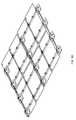
- FIG. 1Ais a perspective view of the solar panel mounting system according to an embodiment of the present invention.
- FIG. 1Cis a top view of the solar panel mounting system of FIG. 1A ;
- FIG. 1Dis an additional perspective view of the solar panel mounting system of FIG. 1A shown with multiple module mounting sections installed;
- FIG. 1Eis a perspective view of an alternate embodiment of the solar panel mounting system, illustrating the components for supporting one panel;
- FIG. 1Fis a perspective view of the embodiment of FIG. 1E showing a plurality of panels installed on the system;
- FIG. 1Gis a perspective view of another embodiment of the solar panel mounting system according to the present invention.
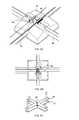
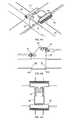
- FIG. 2Ais a perspective view of one embodiment of the foot, link, tilt bracket and panel clamp assembly according to the present invention.
- FIG. 2Bis a top view of one embodiment of the foot, link, tilt bracket and panel clamp assembly according to the present invention.
- FIG. 2Cis a top perspective view of the cruciform and threaded rod assembly embedded in the foot assembly shown in FIG. 2A ;
- FIG. 2Dis cut away section view of the foot and cruciform assembly shown in FIG. 2A ;
- FIG. 2Eis cut away section view of the foot and cruciform assembly with the links, PV panels, tilt bracket, and module clamps shown in FIG. 2A ;
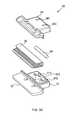
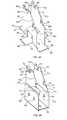
- FIG. 3Ais a perspective view of a panel clamp embodiment according to the present invention.
- FIG. 3Bis an exploded view of the panel clamp of FIG. 3A ;
- FIG. 3Cis an exploded view of an alternate embodiment of the panel clamp
- FIG. 3Dis a top view of the clamp of FIG. 3C ;
- FIG. 4Dis an enlarged view of the clamp attached to a solar panel
- FIG. 4Eis an enlarged side view of an alternative embodiment of the panel clamp for use with panels have an offset lower edge
- FIG. 4Fis a side view of the panel clamp and bracket assembly illustrating the locking tongue on the bottom of the panel clamp
- FIG. 5Ais a perspective view of the tilt bracket that is mounted to the top of the foot assembly
- FIG. 5Bis a perspective view of the tilt bracket that is mounted to the middle of the structural link component
- FIG. 6Ais a plan view of a the solar module array in a basic rectangular formation
- FIG. 6Bis a plan view of a the solar module array in a geometric pattern having more than four corner areas
- FIGS. 7A-7Dillustrate the installation and mounting sequence for a solar panel into the mounting system of the present invention.
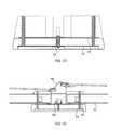
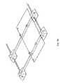
- FIG. 8illustrates the mounting of optional ballast pans onto the mounting system of the present invention.
- the feet 3 a - 3 hare the contact points for the system 1 with the mounting surface (roof or ground). Spanning the distance between the feet and the width of two panels 2 a , 2 b or 2 c , 2 d are long links 4 a - 4 d .
- the long links 4 a - 4 dare preferably installed along a North-South axis direction.
- Connecting the feet along the length of a panelare short links 5 a - 5 f , wherein the short links 5 a - 5 f are preferably installed along an East-West axis direction.
- the long and short linksare preferably formed from roll steel, which is galvanized or powder-coated to prevent corrosion.
- the panels 2 a - 2 dare mounted to the feet 3 a - 3 h via tilt brackets 6 a - 6 h .
- a mid-link bracket 7 a - 7 dconnects to two adjacent panels, 2 a , 2 b or 2 c , 2 d .
- center panel supports 8 a - 8 hmay be mounted on each long link 4 a - 4 d under the centerline of each panel 2 a - 2 d.
- FIG. 1Cis a top view of the system of FIG. 1A .
- the feet 3 a - 3 hare approximately 14 inches square
- the long links 4 a - 4 dare 6-7 ft. long
- the short links 5 a - 5 fare 3-4 ft. long.
- FIG. 1Dfurther illustrates a 4 ⁇ 2 roof top installation. The mounting system's modular design allows it to be easily adapted to different installation size requirements.
- FIG. 1Eillustrates an alternate embodiment of the solar mounting system of the present invention. As shown, each panel is supported by four feet and four links. In this embodiment, note that there are no mid-link brackets, and the feet may be connected using links of a similar size. Such a configuration may be desired in installations having very heavy potential loads.
- FIG. 1Fshows a panel array configured according to the embodiment of FIG. 1E .
- FIG. 1Gillustrates another alternate embodiment of a solar panel mounting system.
- the flexible feet 9 a - 9 fmay be formed as longer elements effectively spanning two links (i.e. 10 a and 10 c ).
- the channel formed in the feet between linksmay itself have a link (i.e. 11 d , 11 f , 11 g , and 11 h ) or the channel may be empty as shown in feet 9 a and 9 d .
- a tilt bracketis installed at each link location in the feet 9 a - 9 f .
- Multiple mid-link brackets 12 a - 12 fmay be installed on the links in each row, such that, for example, four panels are supported between feet elements 9 a , 9 b .
- cross links 11 a , 11 ecan connect feet row-to-row.
- the feet of the embodiment of FIG. 1Gmay be formed as the separate feet illustrated in the previous embodiments, and the feet connected with links as described above.
- FIGS. 2A-2EThe construction of a foot 3 a is shown in greater detail in FIGS. 2A-2E .
- An enlarged view of a foot 3 ais shown in FIG. 2A .
- the foot 3 ais preferably formed of rubber or other flexible material.
- the top of the footcontains two perpendicular slots for attaching the long links and short links.
- a tilt bracketis located generally in the center of the foot ( FIG. 2B ; top view).
- the foot 3 aincludes an upper 20 and lower 21 cruciform, as shown in FIG. 2C .
- the cruciformsare preferably formed from stainless steel. As shown in cross-section in FIG.
- the lower cruciform 21is mounted to the bottom of the rubber foot, and the upper cruciform is attached to the top of the foot, generally aligned with the perpendicular slots.
- a center bolt 22attaches the upper and lower cruciforms 20 , 21 to the foot.
- the lower cruciform 21preferably fits in an indentation shaped like the cruciform in the bottom of the foot.
- the cruciforms 20 , 21could be molded into the foot at the time the foot is manufactured.
- Four threaded rods or studsprotrude through the cruciforms and foot to provide attachment points for the long and short links. The links are attached to the threaded rods with washers and nuts.
- the feetmay be formed with a set of cruciforms on each end.
- the mounting systemacts like an integrated net—sharing the loads when forces pull up on any part of the system.
- the rubber feetact as “nodes” that are able to flex as forces pull the links outward.
- the two cruciformsprovide strength and rigidity to maintain system integrity.
- the long linkstake the down push forces on the solar panels from the wind and snow, and flex at each node.
- the modular designallows the system to be installed on an undulating roof, since the rubber feet can adjust to variations in the mounting surface.
- the long linksi.e. 4 a
- the short linksi.e. 5 a
- the steel bolts through the footare necessarily longer for the long links than for the short links.
- the cruciforms 20 , 21 and a tilt bracketi.e. 6 a
- the long links (i.e. 4 a ) and short links (i.e. 5 a )are attached to the foot using the threaded rods with the washers and nuts.
- the long links and short linksabut the tilt bracket 6 a and overlap the extended bracket sections (see FIG. 5A ).
- FIGS. 3A and 3Billustrate a panel clamp according to a preferred embodiment of the present invention.
- existing mounting systemshave difficulty mounting to a frameless panel, and especially to panels made from two sheets of glass.
- the present clamp 30is designed to mount such frameless panels to the mounting system of the present invention.
- the panel clamp 30includes two main body parts—an upper section 31 and lower 32 section preferably made of cast aluminum. These clamp part sections 31 , 32 are held together by a threaded fastener 34 that is inserted through the top section 31 and threaded into the bottom section 32 of the clamp 30 .
- the fastener 32is preferably a stainless steel bolt having 5/16-18 threads.
- the interface between the assembled clamp halves (clamp “faces”) and the module edgeis filled by a flexible gasket material 33 .
- the flexible gasketis made from Ethylene Propylene Diene Monomer (EPDM) rubber. This material has small, finger-like protrusions that allow for easy insertion onto the module edge, but makes it more difficult to remove the clamps from the module once installed.
- the panel clamp 30is preferably about 4 inches wide and 1 inch high.
- each mounting post 310 , 311On each side of the panel clamp 30 is a mounting post 310 , 311 .
- the mounting post 310 , 311engages the tilt bracket or mid-link bracket as described below.
- the mounting post 310may be formed as part of the upper 310 a and lower 310 b sections, respectively.
- the mounting posts 310 , 311are formed similarly to bolt or screw heads, having a larger outer lip or “head” and an inner “collar” 312 of smaller diameter.
- the mounting postsmay comprise a separate metal element, formed with a head and collar on each end, and held in place between the upper 31 and lower 32 sections.
- each mounting post 310 , 311has the upper and lower portions (edges) of each “collar” 312 of the mounting post flattened off, in order to help prevent rotation of the clamp in a bracket once it is installed.
- FIGS. 3C and 3DAn alternate panel clamp design is illustrated in FIGS. 3C and 3D .
- the panel clamp 35includes an upper section 36 and a lower section 37 .
- Those sections 36 , 37may be formed out of plastic and configured to “snap” fit or glued together. Other materials may be used, and the two sections may be held together by a threaded bolt as previously described.
- the upper sectionincludes two slots 361 , 362 spaced to engage the tilt and mid-link bracket openings.
- the lower sectionincludes slots 371 , 372 aligned with the slots 361 , 362 in the upper section.
- a mounting axle (rod) 38is held in a half channel 373 in the lower section 37 , and a similar half channel (not shown) formed in the upper section 36 .
- the axle 38is held in position by the upper 36 and lower sections 37 , and is generally perpendicular to the slots.
- a grommet 39is positioned between the clamp sections to grip the panel, and may be constructed as noted above.
- FIG. 3Dshows the assembled clamp, and the axle 38 exposed through the slots.
- the panel clamp 35is lowered into a bracket such that the axle 38 engages the mounting openings (described in detail below) in a bracket.
- the panel clampcomprises two pieces.
- the clampsmay be molded as single pieces as well.
- FIGS. 4A , 4 B and 4 Cillustrate two panel clamps attached to a mid-link bracket in an isometric view, side view and top view, respectively.
- One clamp 41attaches to the mid-link bracket at a side position via its mounting posts, effectively making the panel edge lower than the other side.
- a second clamp 42attaches to a top of the mid-link bracket via its mounting posts.
- a locking cap 44may be slid over the top of the top clamp 42 to help prevent uplift forces from disengaging the clamp 42 from the bracket 43 .
- the locking cap 44can be configured to slide over the bracket 43 , which also helps keep the bracket from spreading open under loads.
- the locking cap 44may be formed from metal with the sides bent down, and a in-facing lip on each edge (i.e. forming a block “C” in profile). Each side has a lip to engage the bracket and slides over the top of the bracket to lock into position.
- the mid-link bracket 43preferably slides onto a long link from the bottom, and engages pre-formed holes in the long link. For example, square holes can be punched into the long links to engage indented tabs 431 , 432 punched into the mid-link bracket 43 .
- FIG. 4Dis an enlarged side view of the panel clamp 30 attached to a solar panel. Note that the “fingers” of the rubber grommet material are angled such that the clamp can more easily slide onto a solar panel, but resists the removal of the clamp in the reverse direction. This embodiment is suitable for panels where the top and bottom sheets of glass are aligned.
- the bottom sheet of glassis 0.5 inch or so narrower than the top sheet to allow for the electrical wiring and/or connectors.
- the panelsare formed such that the glass sheets are flush on one edge, and offset on the other. Thus, on one edge of the panel the panel clamps need to account for this offset.
- the rubber grommet 33may be formed with a rectangular filler block 331 to fill in the gap in the edge of the panel.
- the panel clampsare preferably formed with a locking tongue 321 on the bottom of the clamp to engage tabs on the tilt and mid-link brackets (as described below).
- FIG. 5AA detailed view of the tilt bracket is shown in FIG. 5A
- FIG. 5Ba detailed view of the mid-link bracket is shown in FIG. 5B .
- the bracketsare preferably formed from sheet metal as unitary pieces.
- the tilt bracketcomprises two symmetric sides 50 , 51 .
- On the top of each sideis a mounting opening 52 , 53 for a panel clamp mounting post. Behind each mounting opening 52 , 53 is a notch 522 , 532 for engaging the clamp.
- the bracketincludes a tab 521 , 531 on each side of the top to lock the locking cap (not shown) into place.
- a front face of each side 50 , 51has an angled edge 510 , 511 , which helps guide a panel clamp into the lower mounting openings 54 , 55 during installation.
- Each lower mounting opening 54 , 55include a catch 541 , 551 to guide and secure the panel clamp into place.
- the lower mounting openings 54 , 55are deep enough to allow some horizontal movement of the panel clamp in the bracket to facilitate some movement and alignment of a panel during installation.
- Each sidealso includes a locking tab 56 , 57 to engage a locking tongue 321 on a panel clamp. Any upward forces on a panel will cause the panel clamp to try and lift up. However, due to the engagement of the panel clamp with the locking tabs 56 , 57 , the upward force is distributed through the mounting system via the bracket.
- each extensionincludes a lip 601 , 611 , 581 , 591 to “bite” into the links and insure a solid metal-to-metal ground connection.
- the mid-link bracketcomprises two symmetric sides 70 , 71 .
- On the top of each sideis a mounting opening 72 , 73 for a panel clamp mounting post.
- Behind each mounting opening 72 , 73is a notch 722 , 732 for engaging the clamp.
- the bracketincludes a tab 721 , 731 on each side of the top to lock the locking cap (not shown) into place.
- a front face of each side 70 , 71has an angled edge 710 , 711 , which helps guide a panel clamp into the lower mounting openings 74 , 77 during installation.
- Each lower mounting opening 74 , 77include a catch 741 , 751 to guide and secure the panel clamp into place.
- the lower mounting openings 74 , 75are deep enough to allow some horizontal movement of the panel clamp in the bracket to facilitate some movement and alignment of a panel during installation.
- Each sidealso includes a locking tab 76 , 77 to engage a locking tongue 321 on a panel clamp. Any upward forces on a panel will cause the panel clamp to try and lift up. However, due to the engagement of the panel clamp with the locking tabs 76 , 77 , the upward force is distributed through the mounting system via the bracket.
- the mid-link bracketis mounted to a long link, and preferably snaps into place from the bottom of the link.
- the lower portion of the mid-link bracketis configured to conform to the size and shape of a long link.
- the top portion of the mid-link bracketis recessed 701 , 711 to insure a tight fit around the long link.
- alignment and grounding tabs 702 , 703 , 713preferably engage in square holes pre-punched into the long link.
- the front and rear (not shown) of the link channelinclude a lip 78 to improve grounding.
- the size and lengths of the long and short linksmay be adjusted as needed for particular installations.
- the linksmay need to be stronger to support the increased loads.
- the long linksare approximately 15 ⁇ 8′′ ⁇ 23 ⁇ 4′′ in cross-section and the short links are 15 ⁇ 8′′ ⁇ 1′′.
- the linksmay be formed out of a heavier gauge steel.
- the entire mounting systemmay not need to be made out of the thicker steel.
- the long and short linksmay have a uniform external profile, but varied strength depending on a location within a panel array, or the links may have different cross-sections for different applications.
- the mounting systemcan be constructed accordingly.
- the long and short linkscan be constructed out of relatively heavy gauge steel for the perimeter panels, and from thinner (and hence cheaper) steel for the interior panels.
- the respective linkscan be color coded for easy identification by installation personnel.
- the panelis lifted into position over two tilt brackets as shown in FIG. 7A .
- the mounting posts of the panel clampsare aligned with the lower mounting openings in the front of each tilt bracket, and the panel is set into place, as shown in FIG. 7B .
- the panelis then lowered towards the two mid-link brackets as illustrated in FIG. 7C .
- the panelis slid forward into the tilt brackets, and then the panel clamps are aligned and set into the mid-link brackets ( FIG. 7D ).
- the lower mounting openings in the tilt bracketshave enough depth to allow the panel to slide into the bracket, which helps lock the panel in place.
- a locking capis then applied to the top of each mid-link bracket to lock the respective panel clamps in place.
- ballast pans 81 , 82 , 83may be added to the system between adjacent long links. Ballast can then be placed in the pans 81 , 82 , 83 to provide additional weight to the system. Different arrangements and configurations of the ballast pans can be deployed as necessary.
- additional feetcan be placed under to the mid-link brackets to provide additional support.
- the feetare not necessarily attached to the mid-link brackets, but provide additional load bearing support points for the system.
Landscapes
- Engineering & Computer Science (AREA)
- Chemical & Material Sciences (AREA)
- Mechanical Engineering (AREA)
- Sustainable Development (AREA)
- Sustainable Energy (AREA)
- Thermal Sciences (AREA)
- Physics & Mathematics (AREA)
- Combustion & Propulsion (AREA)
- Life Sciences & Earth Sciences (AREA)
- General Engineering & Computer Science (AREA)
- Architecture (AREA)
- Civil Engineering (AREA)
- Structural Engineering (AREA)
- Roof Covering Using Slabs Or Stiff Sheets (AREA)
- Photovoltaic Devices (AREA)
Abstract
Description
Claims (21)
Priority Applications (1)
| Application Number | Priority Date | Filing Date | Title |
|---|---|---|---|
| US13/408,264US8397448B2 (en) | 2009-10-15 | 2012-02-29 | Photovoltaic panel clamp |
Applications Claiming Priority (2)
| Application Number | Priority Date | Filing Date | Title |
|---|---|---|---|
| US12/587,919US8191320B2 (en) | 2009-10-15 | 2009-10-15 | Photovoltaic panel clamp |
| US13/408,264US8397448B2 (en) | 2009-10-15 | 2012-02-29 | Photovoltaic panel clamp |
Related Parent Applications (1)
| Application Number | Title | Priority Date | Filing Date |
|---|---|---|---|
| US12/587,919DivisionUS8191320B2 (en) | 2009-10-15 | 2009-10-15 | Photovoltaic panel clamp |
Publications (2)
| Publication Number | Publication Date |
|---|---|
| US20120152333A1 US20120152333A1 (en) | 2012-06-21 |
| US8397448B2true US8397448B2 (en) | 2013-03-19 |
Family
ID=43876405
Family Applications (2)
| Application Number | Title | Priority Date | Filing Date |
|---|---|---|---|
| US12/587,919Active2029-11-18US8191320B2 (en) | 2009-10-15 | 2009-10-15 | Photovoltaic panel clamp |
| US13/408,264ActiveUS8397448B2 (en) | 2009-10-15 | 2012-02-29 | Photovoltaic panel clamp |
Family Applications Before (1)
| Application Number | Title | Priority Date | Filing Date |
|---|---|---|---|
| US12/587,919Active2029-11-18US8191320B2 (en) | 2009-10-15 | 2009-10-15 | Photovoltaic panel clamp |
Country Status (2)
| Country | Link |
|---|---|
| US (2) | US8191320B2 (en) |
| WO (1) | WO2011046578A1 (en) |
Cited By (27)
| Publication number | Priority date | Publication date | Assignee | Title |
|---|---|---|---|---|
| US20120085395A1 (en)* | 2009-05-12 | 2012-04-12 | Saint-Gobain Glass France | Solar module attachment device and mounting method |
| US8567154B2 (en)* | 2012-02-28 | 2013-10-29 | Johns Manville | Apparatus and methods for mounting a photovoltaic module on a roof |
| US8635818B2 (en) | 2011-03-01 | 2014-01-28 | Ecolibrium Solar, Inc. | System and method for mounting photovoltaic modules |
| US20140083028A1 (en)* | 2011-05-10 | 2014-03-27 | Robert Richardson | Roof solar panel for conventional sloping roof and shingle integration |
| US20140102996A1 (en)* | 2011-10-11 | 2014-04-17 | Todd Pelman | Structure following roof mounted photovoltaic system |
| US8713881B2 (en) | 2012-01-27 | 2014-05-06 | A. Raymond Et Cie | Solar panel securing system |
| USD713784S1 (en) | 2013-06-20 | 2014-09-23 | Ecolibrium Solar, Inc. | Support member for photovoltaic modules |
| US8844215B2 (en)* | 2012-07-10 | 2014-09-30 | Ecolibrium Solar, Inc. | Support assembly for supporting photovoltaic modules |
| US8869471B2 (en)* | 2011-03-01 | 2014-10-28 | Ecolibrium Solar, Inc. | Support assembly for supporting photovoltaic modules |
| US9196755B2 (en) | 2011-03-01 | 2015-11-24 | Ecolibrium Solar, Inc. | Support member for mounting photovoltaic modules and mounting system including the same |
| US9637963B1 (en)* | 2016-04-11 | 2017-05-02 | Emily Patricia Heichel | Hinged connector device |
| US9825581B2 (en) | 2013-11-14 | 2017-11-21 | Ecolibrium Solar, Inc. | Modular sloped roof solar mounting system |
| US10033328B2 (en) | 2011-03-01 | 2018-07-24 | Ecolibrium Solar, Inc. | Support member for mounting photovoltaic modules and mounting system including the same |
| US10218305B1 (en) | 2018-04-16 | 2019-02-26 | Sunmodo Corporation | End clamp for attaching solar panels to roofs |
| US10230324B2 (en) | 2016-03-07 | 2019-03-12 | Ecolibrium Solar, Inc | Support assembly for photovoltaic modules and mounting system using the same |
| US10312853B2 (en) | 2015-03-11 | 2019-06-04 | Ecolibrium Solar, Inc | Sloped roof solar panel mounting system |
| US10340837B2 (en) | 2015-03-11 | 2019-07-02 | Ecolibrium Solar, Inc | Sloped roof solar panel mounting system |
| US10644644B2 (en) | 2011-03-01 | 2020-05-05 | Ecolibrium Solar, Inc. | Support assembly for photovoltaic modules and mounting system using the same |
| US10727781B2 (en) | 2014-12-24 | 2020-07-28 | Ecolibrium Solar, Inc. | Low-sloped roof solar mounting systems |
| US10756668B2 (en) | 2015-03-11 | 2020-08-25 | Ecouni, Llc | Universal sloped roof solar panel mounting system |
| US11050383B2 (en) | 2019-05-21 | 2021-06-29 | Nextracker Inc | Radial cam helix with 0 degree stow for solar tracker |
| US11159120B2 (en) | 2018-03-23 | 2021-10-26 | Nextracker Inc. | Multiple actuator system for solar tracker |
| US11190127B2 (en) | 2011-03-01 | 2021-11-30 | Unirac, Inc. | Support assembly for photovoltaic modules and mounting system using the same |
| US11387771B2 (en) | 2018-06-07 | 2022-07-12 | Nextracker Llc | Helical actuator system for solar tracker |
| US11542970B2 (en) | 2017-07-11 | 2023-01-03 | Illinois Tool Works Inc. | Edge protector |
| US11689148B2 (en) | 2011-03-01 | 2023-06-27 | Unirac Inc. | Support assembly for photovoltaic modules and mounting system using the same |
| US12301159B2 (en) | 2014-11-13 | 2025-05-13 | Unirac Inc. | Modular sloped roof solar mounting system |
Families Citing this family (43)
| Publication number | Priority date | Publication date | Assignee | Title |
|---|---|---|---|---|
| JP4108724B1 (en)* | 2007-02-23 | 2008-06-25 | シャープ株式会社 | Structure installation stand |
| DE102009060498A1 (en)* | 2009-12-23 | 2011-06-30 | Gottlieb Binder GmbH & Co. KG, 71088 | Device for fixing panel-like mats |
| DE202010006442U1 (en)* | 2010-05-04 | 2010-08-19 | Ideematec Deutschland Gmbh | Frame for fixing solar modules |
| US9316416B2 (en) | 2010-10-27 | 2016-04-19 | Gottlieb Binder Gmbh & Co. Kg | Panel arrangement with clamping clip |
| US20160305459A1 (en) | 2010-12-10 | 2016-10-20 | Solar Clam-P | Panel Mounting System and Method |
| WO2012079004A1 (en) | 2010-12-10 | 2012-06-14 | Solar Clam-P, Llc | Panel mounting system and method |
| US9422957B2 (en)* | 2011-02-01 | 2016-08-23 | Thomas & Betts International Llc | Panel clamp |
| US8955259B2 (en) | 2011-06-09 | 2015-02-17 | A. Raymond & Cie | Solar panel attachment system for a roof |
| US8307606B1 (en) | 2011-07-07 | 2012-11-13 | Solon Corporation | Integrated photovoltaic rooftop modules |
| US8745935B2 (en) | 2011-10-14 | 2014-06-10 | A. Raymond Et Cie | Photovoltaic panel fastening system |
| US20130193301A1 (en) | 2012-01-29 | 2013-08-01 | A. Raymond Et Cie | Solar panel attachment system for a roof |
| WO2013119555A2 (en)* | 2012-02-06 | 2013-08-15 | First Solar, Inc. | Mounting clamp and mounting clamp configuration for photovoltaic module installation |
| US9087947B2 (en)* | 2012-06-15 | 2015-07-21 | Kanzo, Inc. | Clamp for mounting solar modules |
| US9316417B2 (en)* | 2012-06-29 | 2016-04-19 | Sunpower Corporation | Framing system for mounting solar collecting devices |
| US10135386B2 (en) | 2012-10-12 | 2018-11-20 | Smash Solar, Inc. | Sensing, interlocking solar module system and installation method |
| US9263985B2 (en) | 2012-11-13 | 2016-02-16 | Pi Solar Technology Gmbh | Rooftop photovoltaic modules |
| US10008975B2 (en) | 2012-12-10 | 2018-06-26 | Nextracker Inc. | Clamp assembly for solar tracker |
| US9766319B2 (en) | 2012-12-10 | 2017-09-19 | Nextracker Inc. | Off-set drive assembly for solar tracker |
| US9466749B1 (en)* | 2012-12-10 | 2016-10-11 | Nextracker Inc. | Balanced solar tracker clamp |
| JP2016504901A (en) | 2012-12-10 | 2016-02-12 | ネクストラッカー インコーポレイテッドNEXTracker Inc. | Horizontal balance solar tracking device |
| US20140318605A1 (en)* | 2013-04-30 | 2014-10-30 | Northern States Metals Company | Panel rack support and protective system for stacking |
| US9196978B2 (en) | 2013-05-03 | 2015-11-24 | Thomas & Betts International Llc | Grounding and bonding bracket |
| US10432132B2 (en) | 2013-07-01 | 2019-10-01 | RBI Solar, Inc. | Solar mounting system having automatic grounding and associated methods |
| NL2011769C2 (en) | 2013-11-08 | 2015-05-11 | Esdec B V | WEAR STRUCTURE FOR SOLAR PANELS AND METHOD FOR MANUFACTURING SUCH A STRUCTURE. |
| NL2012098C2 (en) | 2013-11-08 | 2015-05-11 | Esdec B V | WEAR STRUCTURE FOR SOLAR PANELS AND METHOD FOR MANUFACTURING SUCH A STRUCTURE. |
| TWM483397U (en)* | 2014-01-28 | 2014-08-01 | Sun Rise E & T Corp | Assembled base for solar panel installation |
| DE102014208303B4 (en)* | 2014-05-02 | 2022-09-01 | Werner Ilzhöfer | Fastening device for fastening photovoltaic modules |
| US20180209693A1 (en)* | 2014-07-03 | 2018-07-26 | Basf Se | Plastic Mounting Support For Solar Panels |
| US10256767B1 (en)* | 2014-10-03 | 2019-04-09 | Orion Solar Racking, Inc. | System and method for mounting PV panels in bracket and/or rail mount design |
| MX2017014624A (en)* | 2015-05-18 | 2018-03-01 | Alion Energy Inc | Systems and methods for rotating photovoltaic modules. |
| US9543888B2 (en)* | 2015-06-09 | 2017-01-10 | Nextracker Inc. | Frameless solar module mounting |
| US10361653B2 (en) | 2016-03-25 | 2019-07-23 | Tesci Solar, Inc. | Solar module with integrated mounting components for mounting on a surface |
| WO2017165874A2 (en)* | 2016-03-25 | 2017-09-28 | Tecsi Solar, Inc. | Array including frameless solar modules |
| US11336221B2 (en) | 2016-03-25 | 2022-05-17 | Tecsi Solar, Inc. | Wire receiver for securing wires of solar array |
| US10581375B2 (en)* | 2016-04-14 | 2020-03-03 | David C. Hood | Mounting clip for structure having spaced apart trim |
| US10187007B2 (en) | 2016-04-14 | 2019-01-22 | David C. Hood | Wire cover and mounting bracket |
| US9628019B1 (en)* | 2016-09-09 | 2017-04-18 | Polar Racking Inc. | Photovoltaic panel racking system |
| CN106505939B (en)* | 2016-11-04 | 2018-06-15 | 福建安泰新能源科技有限公司 | A kind of runing rest of solar energy photovoltaic panel |
| US20190207555A1 (en)* | 2016-12-27 | 2019-07-04 | Hall Labs Llc | Solar shingle installation and interconnection system |
| US10707805B2 (en)* | 2016-12-27 | 2020-07-07 | Hall Labs Llc | Roofing underlayment for solar shingles |
| US10931225B2 (en)* | 2018-01-17 | 2021-02-23 | Panelclaw Group, Inc. | Solar module mounting system |
| US10797635B2 (en) | 2018-08-29 | 2020-10-06 | Nextracker Inc. | Solar module mounting bracket assemblies |
| CN114392881B (en)* | 2022-01-20 | 2023-12-19 | 湖南睿麒工程技术服务有限公司 | Photovoltaic board seals glues production line group based on new forms of energy |
Citations (37)
| Publication number | Priority date | Publication date | Assignee | Title |
|---|---|---|---|---|
| US3903669A (en)* | 1974-02-19 | 1975-09-09 | Pease Co | Mounting assembly |
| US3947138A (en)* | 1974-11-27 | 1976-03-30 | Oravisual Company, Inc. | Paper pad clamping fixture |
| US5205072A (en) | 1990-08-21 | 1993-04-27 | Dorma-Glas Gesellschaft Fur Glastur-Beschlage | Shower door or divider |
| US5356675A (en) | 1992-12-28 | 1994-10-18 | Unger Frederick C | Glazing system |
| US5577355A (en)* | 1995-03-14 | 1996-11-26 | Pillar Plastics Limited | Two piece window frame generating from a single extrusion |
| US5588181A (en) | 1995-03-23 | 1996-12-31 | Sutton; Michael R. | Hinge for a glass shower door |
| US5732180A (en) | 1995-06-09 | 1998-03-24 | Multilink, Inc. | Method and apparatus for sealing fiber optic entryways to a sealed enclosure |
| US5746839A (en) | 1996-04-08 | 1998-05-05 | Powerlight Corporation | Lightweight, self-ballasting photovoltaic roofing assembly |
| US5867869A (en) | 1994-10-06 | 1999-02-09 | Chmi | Pressure hinge device for glass door or panel |
| US6063996A (en) | 1996-07-17 | 2000-05-16 | Canon Kabushiki Kaisha | Solar cell module and hybrid roof panel using the same |
| US6070294A (en)* | 1996-09-23 | 2000-06-06 | George Fethers & Co. Trading Pty Ltd | Hinge for a shower screen door |
| US6099097A (en) | 1997-06-26 | 2000-08-08 | Sun Microsystems, Inc. | Snap-fit door hinge assembly and method |
| US6481055B2 (en) | 2001-04-10 | 2002-11-19 | Ko Ming Cheng | Pivotal device for a frameless glass door |
| US20030000569A1 (en) | 2001-06-28 | 2003-01-02 | Dutch Space B.V. | Solar panel with corrugated thin film cells |
| US6546682B1 (en)* | 2001-10-10 | 2003-04-15 | Odl, Incorporated | Hurricane door light |
| US20030070368A1 (en) | 2001-10-12 | 2003-04-17 | Jefferson Shingleton | Solar module mounting method and clip |
| US6560821B2 (en) | 2001-02-09 | 2003-05-13 | The Group Legacy L.C. | Glass door hinge |
| US6570084B2 (en) | 2001-07-10 | 2003-05-27 | Powerlight Corporation | Pressure equalizing photovoltaic assembly and method |
| US20030098056A1 (en) | 2001-11-26 | 2003-05-29 | Fronek Steven B. | Window structure with photovoltaic panel |
| US20030101662A1 (en) | 2000-01-14 | 2003-06-05 | Ullman Stanley A. | Mounting system for supporting objects |
| US20040068942A1 (en)* | 2002-10-09 | 2004-04-15 | Krochmal Andrew R. | Screwless window frame assembly |
| US6766561B1 (en) | 2003-03-28 | 2004-07-27 | Ko-Ming Cheng | Frameless glass door hinge |
| US6809251B2 (en) | 2001-07-10 | 2004-10-26 | Powerlight Corporation | Inclined photovoltaic assembly |
| US20040250491A1 (en) | 2001-10-29 | 2004-12-16 | Diaz Emilio Mera | Low ballast mounting system |
| US20050005534A1 (en) | 2001-09-28 | 2005-01-13 | Kaneka Corporation | Solar cell module, method of laying solar cell modules, and apparatus for preventing solar cell modules from being blown off |
| US20050115176A1 (en) | 2002-04-11 | 2005-06-02 | Rwe Schott Solar, Inc. | Apparatus and method for mounting photovoltaic power generating systems on buildings |
| US6968654B2 (en) | 2003-01-08 | 2005-11-29 | Mcconnell Energy Solutions, Llc | Solar panel mounting structure, solar panel system, and methods of making and installing thereof |
| US20060053706A1 (en) | 2002-04-11 | 2006-03-16 | Rwe Schott Solar Inc. | Apparatus for mounting photovoltaic power generating systems on buildings |
| US20060118163A1 (en) | 2004-02-13 | 2006-06-08 | Kineo Design Group, Llc | Rack assembly for mounting solar modules |
| US7114292B2 (en) | 2003-04-11 | 2006-10-03 | Fanny Chiang | Adjustable automatic positioning hinge for glass doors |
| US20060288645A1 (en) | 2005-06-10 | 2006-12-28 | Cpi International Inc. | Method and apparatus for selective solar control |
| US7188390B2 (en) | 2005-03-15 | 2007-03-13 | Ko-Ming Cheng | Adjustable hinge for a glass door |
| US20070120381A1 (en) | 2005-11-15 | 2007-05-31 | Jakob Ehrensvard | Electronic tamper evident seal |
| US7240400B2 (en) | 2003-10-23 | 2007-07-10 | Brent Bonham | Vertical and horizontal adjustable hinge assembly |
| US7305797B2 (en) | 2006-03-31 | 2007-12-11 | Fanny Chiang | Door-closing assembly of frameless glass door |
| US20080083087A1 (en) | 2006-10-06 | 2008-04-10 | Lin Kun Ta Industrial Co., Ltd. | Glass door hinge structure |
| US20090199846A1 (en) | 2008-02-11 | 2009-08-13 | Collins Kenneth D | Solar Roof Tracker |
- 2009
- 2009-10-15USUS12/587,919patent/US8191320B2/enactiveActive
- 2010
- 2010-08-12WOPCT/US2010/002224patent/WO2011046578A1/enactiveApplication Filing
- 2012
- 2012-02-29USUS13/408,264patent/US8397448B2/enactiveActive
Patent Citations (37)
| Publication number | Priority date | Publication date | Assignee | Title |
|---|---|---|---|---|
| US3903669A (en)* | 1974-02-19 | 1975-09-09 | Pease Co | Mounting assembly |
| US3947138A (en)* | 1974-11-27 | 1976-03-30 | Oravisual Company, Inc. | Paper pad clamping fixture |
| US5205072A (en) | 1990-08-21 | 1993-04-27 | Dorma-Glas Gesellschaft Fur Glastur-Beschlage | Shower door or divider |
| US5356675A (en) | 1992-12-28 | 1994-10-18 | Unger Frederick C | Glazing system |
| US5867869A (en) | 1994-10-06 | 1999-02-09 | Chmi | Pressure hinge device for glass door or panel |
| US5577355A (en)* | 1995-03-14 | 1996-11-26 | Pillar Plastics Limited | Two piece window frame generating from a single extrusion |
| US5588181A (en) | 1995-03-23 | 1996-12-31 | Sutton; Michael R. | Hinge for a glass shower door |
| US5732180A (en) | 1995-06-09 | 1998-03-24 | Multilink, Inc. | Method and apparatus for sealing fiber optic entryways to a sealed enclosure |
| US5746839A (en) | 1996-04-08 | 1998-05-05 | Powerlight Corporation | Lightweight, self-ballasting photovoltaic roofing assembly |
| US6063996A (en) | 1996-07-17 | 2000-05-16 | Canon Kabushiki Kaisha | Solar cell module and hybrid roof panel using the same |
| US6070294A (en)* | 1996-09-23 | 2000-06-06 | George Fethers & Co. Trading Pty Ltd | Hinge for a shower screen door |
| US6099097A (en) | 1997-06-26 | 2000-08-08 | Sun Microsystems, Inc. | Snap-fit door hinge assembly and method |
| US20030101662A1 (en) | 2000-01-14 | 2003-06-05 | Ullman Stanley A. | Mounting system for supporting objects |
| US6560821B2 (en) | 2001-02-09 | 2003-05-13 | The Group Legacy L.C. | Glass door hinge |
| US6481055B2 (en) | 2001-04-10 | 2002-11-19 | Ko Ming Cheng | Pivotal device for a frameless glass door |
| US20030000569A1 (en) | 2001-06-28 | 2003-01-02 | Dutch Space B.V. | Solar panel with corrugated thin film cells |
| US6570084B2 (en) | 2001-07-10 | 2003-05-27 | Powerlight Corporation | Pressure equalizing photovoltaic assembly and method |
| US6809251B2 (en) | 2001-07-10 | 2004-10-26 | Powerlight Corporation | Inclined photovoltaic assembly |
| US20050005534A1 (en) | 2001-09-28 | 2005-01-13 | Kaneka Corporation | Solar cell module, method of laying solar cell modules, and apparatus for preventing solar cell modules from being blown off |
| US6546682B1 (en)* | 2001-10-10 | 2003-04-15 | Odl, Incorporated | Hurricane door light |
| US20030070368A1 (en) | 2001-10-12 | 2003-04-17 | Jefferson Shingleton | Solar module mounting method and clip |
| US20040250491A1 (en) | 2001-10-29 | 2004-12-16 | Diaz Emilio Mera | Low ballast mounting system |
| US20030098056A1 (en) | 2001-11-26 | 2003-05-29 | Fronek Steven B. | Window structure with photovoltaic panel |
| US20050115176A1 (en) | 2002-04-11 | 2005-06-02 | Rwe Schott Solar, Inc. | Apparatus and method for mounting photovoltaic power generating systems on buildings |
| US20060053706A1 (en) | 2002-04-11 | 2006-03-16 | Rwe Schott Solar Inc. | Apparatus for mounting photovoltaic power generating systems on buildings |
| US20040068942A1 (en)* | 2002-10-09 | 2004-04-15 | Krochmal Andrew R. | Screwless window frame assembly |
| US6968654B2 (en) | 2003-01-08 | 2005-11-29 | Mcconnell Energy Solutions, Llc | Solar panel mounting structure, solar panel system, and methods of making and installing thereof |
| US6766561B1 (en) | 2003-03-28 | 2004-07-27 | Ko-Ming Cheng | Frameless glass door hinge |
| US7114292B2 (en) | 2003-04-11 | 2006-10-03 | Fanny Chiang | Adjustable automatic positioning hinge for glass doors |
| US7240400B2 (en) | 2003-10-23 | 2007-07-10 | Brent Bonham | Vertical and horizontal adjustable hinge assembly |
| US20060118163A1 (en) | 2004-02-13 | 2006-06-08 | Kineo Design Group, Llc | Rack assembly for mounting solar modules |
| US7188390B2 (en) | 2005-03-15 | 2007-03-13 | Ko-Ming Cheng | Adjustable hinge for a glass door |
| US20060288645A1 (en) | 2005-06-10 | 2006-12-28 | Cpi International Inc. | Method and apparatus for selective solar control |
| US20070120381A1 (en) | 2005-11-15 | 2007-05-31 | Jakob Ehrensvard | Electronic tamper evident seal |
| US7305797B2 (en) | 2006-03-31 | 2007-12-11 | Fanny Chiang | Door-closing assembly of frameless glass door |
| US20080083087A1 (en) | 2006-10-06 | 2008-04-10 | Lin Kun Ta Industrial Co., Ltd. | Glass door hinge structure |
| US20090199846A1 (en) | 2008-02-11 | 2009-08-13 | Collins Kenneth D | Solar Roof Tracker |
Cited By (41)
| Publication number | Priority date | Publication date | Assignee | Title |
|---|---|---|---|---|
| US8763346B2 (en)* | 2009-05-12 | 2014-07-01 | Saint-Gobain Glass France | Solar module attachment device and mounting method |
| US20120085395A1 (en)* | 2009-05-12 | 2012-04-12 | Saint-Gobain Glass France | Solar module attachment device and mounting method |
| US9196755B2 (en) | 2011-03-01 | 2015-11-24 | Ecolibrium Solar, Inc. | Support member for mounting photovoltaic modules and mounting system including the same |
| US11190127B2 (en) | 2011-03-01 | 2021-11-30 | Unirac, Inc. | Support assembly for photovoltaic modules and mounting system using the same |
| US10644644B2 (en) | 2011-03-01 | 2020-05-05 | Ecolibrium Solar, Inc. | Support assembly for photovoltaic modules and mounting system using the same |
| US11689148B2 (en) | 2011-03-01 | 2023-06-27 | Unirac Inc. | Support assembly for photovoltaic modules and mounting system using the same |
| US8635818B2 (en) | 2011-03-01 | 2014-01-28 | Ecolibrium Solar, Inc. | System and method for mounting photovoltaic modules |
| US10033328B2 (en) | 2011-03-01 | 2018-07-24 | Ecolibrium Solar, Inc. | Support member for mounting photovoltaic modules and mounting system including the same |
| US9413285B2 (en) | 2011-03-01 | 2016-08-09 | Ecolibrium Solar, Inc. | Support member for mounting photovoltaic modules |
| US8869471B2 (en)* | 2011-03-01 | 2014-10-28 | Ecolibrium Solar, Inc. | Support assembly for supporting photovoltaic modules |
| US20140083028A1 (en)* | 2011-05-10 | 2014-03-27 | Robert Richardson | Roof solar panel for conventional sloping roof and shingle integration |
| US8991116B2 (en)* | 2011-05-10 | 2015-03-31 | Robert Richardson | Roof solar panel for conventional sloping roof and shingle integration |
| US20140102996A1 (en)* | 2011-10-11 | 2014-04-17 | Todd Pelman | Structure following roof mounted photovoltaic system |
| US9038329B2 (en)* | 2011-10-11 | 2015-05-26 | Sunlink Corporation | Structure following roof mounted photovoltaic system |
| US8713881B2 (en) | 2012-01-27 | 2014-05-06 | A. Raymond Et Cie | Solar panel securing system |
| US8567154B2 (en)* | 2012-02-28 | 2013-10-29 | Johns Manville | Apparatus and methods for mounting a photovoltaic module on a roof |
| US8844215B2 (en)* | 2012-07-10 | 2014-09-30 | Ecolibrium Solar, Inc. | Support assembly for supporting photovoltaic modules |
| USD713784S1 (en) | 2013-06-20 | 2014-09-23 | Ecolibrium Solar, Inc. | Support member for photovoltaic modules |
| US9825581B2 (en) | 2013-11-14 | 2017-11-21 | Ecolibrium Solar, Inc. | Modular sloped roof solar mounting system |
| US10270383B2 (en) | 2013-11-14 | 2019-04-23 | Ecolibrium Solar, Inc | Modular sloped roof solar mounting system |
| US10917032B2 (en) | 2013-11-14 | 2021-02-09 | Ecouni, Llc | Modular sloped roof solar mounting system |
| US10622936B2 (en) | 2013-11-14 | 2020-04-14 | Ecolibrium Solar, Inc | Modular sloped roof solar mounting system |
| US12301159B2 (en) | 2014-11-13 | 2025-05-13 | Unirac Inc. | Modular sloped roof solar mounting system |
| US10727781B2 (en) | 2014-12-24 | 2020-07-28 | Ecolibrium Solar, Inc. | Low-sloped roof solar mounting systems |
| US10312853B2 (en) | 2015-03-11 | 2019-06-04 | Ecolibrium Solar, Inc | Sloped roof solar panel mounting system |
| US10340837B2 (en) | 2015-03-11 | 2019-07-02 | Ecolibrium Solar, Inc | Sloped roof solar panel mounting system |
| US10756668B2 (en) | 2015-03-11 | 2020-08-25 | Ecouni, Llc | Universal sloped roof solar panel mounting system |
| US11757398B2 (en) | 2015-03-11 | 2023-09-12 | Unirac Inc. | Universal sloped roof solar panel mounting system |
| US10230324B2 (en) | 2016-03-07 | 2019-03-12 | Ecolibrium Solar, Inc | Support assembly for photovoltaic modules and mounting system using the same |
| US9637963B1 (en)* | 2016-04-11 | 2017-05-02 | Emily Patricia Heichel | Hinged connector device |
| US11542970B2 (en) | 2017-07-11 | 2023-01-03 | Illinois Tool Works Inc. | Edge protector |
| US12218626B2 (en) | 2018-03-23 | 2025-02-04 | Nextracker Llc | Multiple actuator system for solar tracker |
| US11711051B2 (en) | 2018-03-23 | 2023-07-25 | Nextracker Llc | Multiple actuator system for solar tracker |
| US11283395B2 (en) | 2018-03-23 | 2022-03-22 | Nextracker Inc. | Multiple actuator system for solar tracker |
| US11159120B2 (en) | 2018-03-23 | 2021-10-26 | Nextracker Inc. | Multiple actuator system for solar tracker |
| US12237804B2 (en) | 2018-03-23 | 2025-02-25 | Nextracker Llc | Multiple actuator system for solar tracker |
| US10218305B1 (en) | 2018-04-16 | 2019-02-26 | Sunmodo Corporation | End clamp for attaching solar panels to roofs |
| US11387771B2 (en) | 2018-06-07 | 2022-07-12 | Nextracker Llc | Helical actuator system for solar tracker |
| US11705859B2 (en) | 2019-05-21 | 2023-07-18 | Nextracker Llc | Radial cam helix with 0 degree stow for solar tracker |
| US11050383B2 (en) | 2019-05-21 | 2021-06-29 | Nextracker Inc | Radial cam helix with 0 degree stow for solar tracker |
| US12308786B2 (en) | 2019-05-21 | 2025-05-20 | Nextracker Llc | Radial cam helix with 0 degree stow for solar tracker |
Also Published As
| Publication number | Publication date |
|---|---|
| US8191320B2 (en) | 2012-06-05 |
| US20120152333A1 (en) | 2012-06-21 |
| US20110088740A1 (en) | 2011-04-21 |
| WO2011046578A1 (en) | 2011-04-21 |
Similar Documents
| Publication | Publication Date | Title |
|---|---|---|
| US8397448B2 (en) | Photovoltaic panel clamp | |
| US8266848B2 (en) | Photovoltaic module mounting system | |
| US8615939B2 (en) | Photovoltaic module mounting system | |
| US20100089390A1 (en) | Solar array mounting system | |
| US7592537B1 (en) | Method and apparatus for mounting photovoltaic modules | |
| US9551510B2 (en) | Slider clip and photovoltaic structure mounting system | |
| US10547270B2 (en) | Building integrated photovoltaic roofing assemblies and associated systems and methods | |
| US10365017B2 (en) | Self-adjusting end clamp | |
| US8511009B2 (en) | Securing configuration of solar cell module | |
| US8539719B2 (en) | Module attachment apparatus | |
| US20110154774A1 (en) | System and Method for Passively Securing Solar Panels to a Flat Surface | |
| JP2001291889A (en) | Photovoltaic generator | |
| JP2001152619A (en) | Support structure of solar-cell panel | |
| US20090056792A1 (en) | Interconnecting support panel providing substantially planar upper surface | |
| JP2001090274A (en) | Mounting structure of solar-cell module | |
| Brown et al. | Photovoltaic panel clamp | |
| AU2018267679B2 (en) | A solar roof sheet assembly | |
| JPH0616557U (en) | Roof panel with solar cells | |
| CN117365019A (en) | Photovoltaic tile system | |
| JP2004263454A (en) | Solar power generation module |
Legal Events
| Date | Code | Title | Description |
|---|---|---|---|
| STCF | Information on status: patent grant | Free format text:PATENTED CASE | |
| AS | Assignment | Owner name:UNION BAY CAPITAL PARTNERS I, LLC, WASHINGTON Free format text:SECURITY INTEREST;ASSIGNOR:SUNLINK CORPORATION;REEL/FRAME:034229/0303 Effective date:20141114 | |
| AS | Assignment | Owner name:SILICON VALLEY BANK, CALIFORNIA Free format text:SECURITY INTEREST;ASSIGNOR:SUNLINK CORPORATION;REEL/FRAME:035973/0791 Effective date:20150604 | |
| FPAY | Fee payment | Year of fee payment:4 | |
| AS | Assignment | Owner name:SUNLINK CORPORATION, CALIFORNIA Free format text:RELEASE BY SECURED PARTY;ASSIGNOR:SILICON VALLEY BANK;REEL/FRAME:041664/0352 Effective date:20170208 | |
| AS | Assignment | Owner name:HERITAGE BANK OF COMMERCE, CALIFORNIA Free format text:SECURITY INTEREST;ASSIGNOR:SUNLINK CORPORATION;REEL/FRAME:041208/0133 Effective date:20170207 | |
| AS | Assignment | Owner name:MULTIPLIER CAPITAL II, LP, MARYLAND Free format text:SECURITY INTEREST;ASSIGNOR:SUNLINK CORPORATION;REEL/FRAME:044438/0374 Effective date:20170929 | |
| AS | Assignment | Owner name:NANOSOLAR, INC., CALIFORNIA Free format text:ASSIGNMENT OF ASSIGNORS INTEREST;ASSIGNORS:BROWN, MALCOLM P.;STANCEL, ROBERT;REEL/FRAME:049905/0026 Effective date:20091103 Owner name:SUNLINK CORPORATION, CALIFORNIA Free format text:ASSIGNMENT OF ASSIGNORS INTEREST;ASSIGNORS:MITTAN, MARGARET BIRMINGHAM;MIROS, ROBERT H.J.;REEL/FRAME:049905/0353 Effective date:20091106 | |
| AS | Assignment | Owner name:MULTIPLIER CAPITAL II ACQUISITION, LLC, DISTRICT OF COLUMBIA Free format text:ASSIGNMENT OF ASSIGNORS INTEREST;ASSIGNOR:SUNLINK CORPORATION;REEL/FRAME:052000/0846 Effective date:20200227 | |
| AS | Assignment | Owner name:COROSOLAR LLC, ARIZONA Free format text:ASSIGNMENT OF ASSIGNORS INTEREST;ASSIGNOR:MULTIPLIER CAPITAL II ACQUISITION LLC;REEL/FRAME:052033/0179 Effective date:20200304 | |
| MAFP | Maintenance fee payment | Free format text:PAYMENT OF MAINTENANCE FEE, 8TH YR, SMALL ENTITY (ORIGINAL EVENT CODE: M2552); ENTITY STATUS OF PATENT OWNER: SMALL ENTITY Year of fee payment:8 | |
| FEPP | Fee payment procedure | Free format text:ENTITY STATUS SET TO UNDISCOUNTED (ORIGINAL EVENT CODE: BIG.); ENTITY STATUS OF PATENT OWNER: LARGE ENTITY | |
| MAFP | Maintenance fee payment | Free format text:PAYMENT OF MAINTENANCE FEE, 12TH YEAR, LARGE ENTITY (ORIGINAL EVENT CODE: M1553); ENTITY STATUS OF PATENT OWNER: LARGE ENTITY Year of fee payment:12 |