US8397418B2 - System for providing electrical power to accessories mounted on the powered - Google Patents
System for providing electrical power to accessories mounted on the poweredDownload PDFInfo
- Publication number
- US8397418B2 US8397418B2US13/075,857US201113075857AUS8397418B2US 8397418 B2US8397418 B2US 8397418B2US 201113075857 AUS201113075857 AUS 201113075857AUS 8397418 B2US8397418 B2US 8397418B2
- Authority
- US
- United States
- Prior art keywords
- weapon
- power
- power source
- receiver extension
- distribution system
- Prior art date
- Legal status (The legal status is an assumption and is not a legal conclusion. Google has not performed a legal analysis and makes no representation as to the accuracy of the status listed.)
- Expired - Fee Related
Links
Images


Classifications
- F—MECHANICAL ENGINEERING; LIGHTING; HEATING; WEAPONS; BLASTING
- F41—WEAPONS
- F41C—SMALLARMS, e.g. PISTOLS, RIFLES; ACCESSORIES THEREFOR
- F41C27/00—Accessories; Details or attachments not otherwise provided for
- F—MECHANICAL ENGINEERING; LIGHTING; HEATING; WEAPONS; BLASTING
- F41—WEAPONS
- F41C—SMALLARMS, e.g. PISTOLS, RIFLES; ACCESSORIES THEREFOR
- F41C23/00—Butts; Butt plates; Stocks
- F41C23/22—Stocks having space for the storage of objects
- F—MECHANICAL ENGINEERING; LIGHTING; HEATING; WEAPONS; BLASTING
- F41—WEAPONS
- F41G—WEAPON SIGHTS; AIMING
- F41G11/00—Details of sighting or aiming apparatus; Accessories
- F41G11/001—Means for mounting tubular or beam shaped sighting or aiming devices on firearms
- F41G11/003—Mountings with a dove tail element, e.g. "Picatinny rail systems"
Definitions
- the inventionrelates generally to the field of electrical power distribution and, more particularly, to a system for providing electric power to power-consuming accessories which are mounted on a powered rail of a weapon.
- the Powered Railmust have a method of electrically connecting the power-consuming accessory to a common power source which is operationally associated with the weapon.
- the implementation of a common power sourcemust be done in a manner to maintain balance of the weapon for ease of use and also simplicity of re-provisioning the batteries in the common power source.
- a firearm used in military applicationsmay have a plurality of accessories that can be attached to the weapon, with each accessory having a need for electric power.
- a common power sourceis used to power whatever power-consuming accessory is attached to the weapon.
- a Weapon Accessory Power Distribution Systemprovides one or more powered rails to provide a point of mechanical and electrical interconnection for the power-consuming accessories to provide quick connect mounting and dismounting of the power-consuming accessory, absent the use of connectors with their tethering cables, which are susceptible to entanglement.
- the powered rail(s)are electrically interconnected with the present Weapon Accessory Power Source, which can be a battery mounted in the butt stock of the weapon, a pistol grip mounted power source, a powered rail mounted power source, or an external power source electrically connected to the powered rail.
- the power transfer between the power source and the powered railuses a permanent power distribution system mounted on the weapon.
- the Weapon Accessory Power Distribution Systemis designed for use in an unprotected manner where the components are exposed to harsh ambient environmental conditions.
- the Weapon Accessory Power Distribution Systemprovides the following benefits:
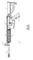
- FIGS. 1A-1Care illustrations of the prior art Picatinny Rail mounted on a military style weapon, which is used to mount accessories to the weapon as is well known in the art;
- FIGS. 2A and 2Bare illustrations of the system architecture of a military style weapon equipped with a Weapon Accessory Power Distribution System
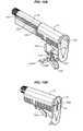
- FIGS. 3A and 3Bare illustrations of a typical butt stock battery pack of the Weapon Accessory Power Source
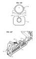
- FIGS. 4A-4Care illustrations of the Power Distribution System which interconnects the Battery Pack to the Powered Rail in the Weapon Accessory Power Distribution System;
- FIGS. 5A-5Care illustrations of the Handguard assembly, including the Powered Rail, of the Weapon Accessory Power Distribution System;
- FIGS. 6A and 6Bare plan and perspective views, respectively, of two implementations of the printed circuit board used to implement the Powered Rail, while FIG. 6C is an exploded perspective view of the printed circuit board used to implement the Powered Rail;
- FIGS. 7A and 7Billustrate the details of the Powered Rail electrical interconnection
- FIGS. 8A-8Care illustrations of the typical mechanical interconnection and electrical interconnection of a Power-Consuming Accessory to the Handguard and Powered Rail;
- FIG. 9is a schematic of loose mesh grid disks, plain side up and solder side up, which are used to implement the Low Reflectivity Contact;
- FIG. 10is an illustration of a Low Reflectivity Contact soldered to a Printed Circuit Board
- FIGS. 11A and 11Bare illustrations of the light reflectivity geometry of the Low Reflectivity Contact
- FIGS. 12A-12Iare illustrations of details of the butt stock version of the Weapon Accessory Power Source
- FIGS. 13A and 13Bare illustrations of details of the pistol grip version of the Weapon Accessory Power Source
- FIGS. 14A-14Care illustrations of details of the powered rail version of the Weapon Accessory Power Source.
- FIGS. 15A and 15Billustrate details of the external version of the Weapon Accessory Power Source.
- ContactOne-half of a Contact Pair consisting of an electrically conductive surface which is electrically connected to a power source or power-consuming device.
- Contact PairA set of two Contacts which, when brought together in mechanical contact, complete an electrical circuit enabling the transfer of electrical power and/or electrical signals therebetween.
- Visible SpectrumThe visible spectrum is the portion of the electromagnetic spectrum that is visible to (can be detected by) the human eye. Electromagnetic radiation in this range of wavelengths is called “visible light” or simply “light”. A typical human eye responds to wavelengths from about 390 nm to 750 nm. In terms of frequency, this corresponds to a band in the vicinity of 400 THz to 790 THz.
- Electrical Resistivityis a measure of how strongly a material opposes the flow of electric current. A low resistivity indicates a material that readily allows the movement of electrical charge.
- Electrical Conductivity(the inverse of Electrical Resistivity) is a measure of how strongly a material supports the flow of electric current. A high conductivity indicates a material that readily allows the movement of electrical charge.
- rapid fire firearmsutilized particularly in military operations, are characterized by the heating of the barrel of the weapon to relatively high temperatures. At such temperatures, the barrel cannot be held safely by the person firing the weapon. Consequently, a variety of handguards have been developed to shroud the barrel of such rapid fire weapons to enable the person firing the weapon to grip the forward portion of the weapon while mitigating the possibility of burning the hand of the person firing the weapon, yet also providing adequate cooling for the barrel of the weapon.
- FIGS. 1A-1Care illustrations of the prior art Picatinny Rail mounted on a military style weapon 1 , which is used to mount accessories to the weapon as is well known in the art.
- the weapon 1contains the standard components, such as receiver 2 , grip 3 , barrel 4 , handguard 5 , 6 , butt stock 7 , and front sight 8 .
- the Picatinny Rail or MIL-STD-1913 rail(and NATO equivalent—STANAG 4694) is a bracket used on some firearms to provide a standardized accessory mounting platform. Its name comes from the Picatinny Arsenal in New Jersey, USA where it was originally tested and was used to distinguish it from other rail standards at the time.
- the Picatinny Railcomprises a series of ridges with a T-shaped cross-section interspersed with flat “locking slots” (also termed “recoil groove”). Scopes are mounted either by sliding them on from one end of the Picatinny Rail or the other end of the Picatinny Rail by means of a “rail-grabber” which is clamped to the Picatinny Rail with bolts, thumbscrews, or levers, or onto the slots between the raised sections. Scopes and other accessories can also (and usually are) mounted from the sides of the rail, not just slid over the ends.
- the Picatinny Railis shown as integrated into handguard 5 , 6 , which includes a top semi-cylindrical (C) part 11 and a bottom semi-cylindrical (C) part 12 .
- the top semi-cylindrical part 11is defined by a back end having a back end ledge that engages with a slip ring and a front end having a front end ledge that engages with the receptor cap to retain the part 11 about the barrel 4 .
- the bottom part 12is defined by a back end having a back end ledge that engages with the slip ring and a front end having a front end ledge that engages with the receptor cap to retain the part 12 about the barrel 4 .
- An accessory adapter rail 13extends longitudinally and upwardly from the top semi-cylindrical part 11 .
- the handguard 5 , 6may also include accessory adapter side rails and accessory adapter bottom rails.
- the Picatinny Railis formed of a multi-faceted (F 1 -F 4 ) structure, on each facet of which accessories can be mounted. Apertures A are provided along the length dimension L of the Picatinny Rail to enable the barrel 4 of the weapon 1 to be cooled by air circulation from the ambient environment.
- the Picatinny Railwas originally designed for use with scopes. However, once established, the use of the Picatinny Rail was expanded to other accessories, such as tactical lights, laser aiming modules, night vision devices, reflex sights, fore grips, bipods, and bayonets. Because the Picatinny Rail was originally designed and used for telescopic sights, the rails were first used only on the receivers of larger caliber rifles. However, their use has extended to the point that Picatinny Rails and accessories have replaced iron sights in the design of many firearms, and they are also incorporated into the undersides of semi-automatic pistol frames and even on grips.
- the railIn order to provide a stable platform, the rail should not flex as the barrel heats and cools; this is the purpose of the locking slots: they give the rail considerable room to expand and contract lengthwise without distorting its shape.
- an accessory for a weaponis a scope which includes a reticle which can be illuminated for use in low light or daytime conditions.
- the reticleis a grid of fine lines in the focus of the scope, used for determining the position of the target.
- a reticle that is too brightcauses glare in the operator's eye, interfering with his ability to see in low light conditions. This is because the pupil of the human eye closes quickly upon receiving any source of light.
- Most illuminated reticlesprovide adjustable brightness settings to adjust the reticle precisely to the ambient light. Illumination is usually provided by a battery powered LED, though other electric light sources can be used.
- the lightis projected forward through the scope and reflects off the back surface of the reticle. Red is the most common color used, as it least impedes the shooter's night vision. This illumination method can be used to provide both daytime and low light conditions reticle illumination.
- powered accessoriesinclude, but are not limited to: tactical lights, laser aiming modules, and night vision devices.
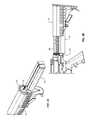
- FIGS. 2A and 2Bare illustrations of the system architecture of a weapon 2 equipped with a Weapon Accessory Power Distribution System.
- the primary components of the basic Weapon Accessory Power Distribution System as noted aboveare:
- the existing weapon 2includes in well-known fashion an upper receiver 101 , lower receiver 102 , barrel 103 , muzzle 104 , grip 105 , and front sight 106 . While a military-style weapon is described herein, the teachings of this application are equally applicable to other firearms, such as handguns, fixed-mount machine guns, as well as non-weapons based systems.
- the Weapon Accessory Power Distribution Systemis added to this standard military-style weapon 2 as described herein.
- the Handguard 23performs the barrel shielding function as in the Picatinny Rail noted above, but has been modified, as shown in FIGS. 2A and 2B , to accommodate the Powered Rail 24 and electrical interconnection of the Powered Accessory Mounting 25 to the Powered Rail 24 , as described below.
- a combination of Powered Rails 24 and Handguard sections 23are attached together to form a structure which typically encircles the barrel 103 .
- the Powered Rails 24in effect form facets around the periphery of the resultant Handguard structure.
- the term “Handguard”is used to represent the sections of a handguard structure as well as the well-known combination of Handguard sections and Powered Rails which encircle the barrel 103 as shown in FIGS.
- the Powered Rail 24can be attached to a Handguard 23 that encircles the barrel. Furthermore, there is no requirement to use the Handguard 23 as an integral component of the Weapon Accessory Power Distribution System, so the Handguard 23 can be optional, with the Powered Rail(s) 24 being attached to the weapon in some other manner, such as an upper receiver rail 101 in FIG. 2A .
- the first of the above-listed configurationsis used herein.
- the Handguard 23was developed to shroud the barrel 103 of a rapid fire weapon 2 to enable the person firing the weapon 2 to grip the forward portion of the weapon 2 while mitigating the possibility of burning the hand of the person firing the weapon 2 , yet also providing adequate cooling for the barrel 103 of the weapon.
- Handguardsfind application in rifles, carbines, and fixed-mount weapons, such as machine guns.
- the Weapon Accessory Power Distribution Systemcan also be used in modified form for handguns, as an accessory mounting platform and as an accessory power source.
- FIGS. 5A-5Care perspective exploded view, side view, and end view illustrations, respectively, of the Handguard 23 assembly, including the Powered Rail 24 , of the Weapon Accessory Power Distribution System.
- the Powered Rail 24as shown as an example, includes a series of ridges with a T-shaped cross-section interspersed with flat “locking slots”.
- This version of the Handguard 23therefore, can be viewed as an adaptation of the existing non-powered Picatinny Rail which involves milling slots along the length of the mechanical accessory attachment points 23 R in the upper Handguard section ( 23 U) and the lower Handguard section ( 23 L) in order to install one or more power distribution Printed Circuit Boards 60 - 1 to 60 - 4 , with FIG.
- FIG. 5Cshowing an end view of the slots formed in the various facets F 1 -F 4 of the Handguard 23 .
- Apertures Aare provided along the length dimension L of the Handguard 23 to enable the barrel 103 of the weapon 2 to be cooled by air circulation from the ambient environment.
- Other Powered Rail configurationsare possible, and this architecture is provided as an illustration of the concepts of the Weapon Accessory Power Distribution System.
- One or more of the Powered Rail subassemblies (typically Printed Circuit Boards) 60 - 1 to 60 - 4can be inserted into the respective slots formed in the Powered Rail 24 (on the corresponding facets F 1 -F 4 of the Handguard 23 ) thereby to enable power-consuming accessories to be attached to the Handguard 23 of the weapon 2 via the Powered Rail 24 on any facet F 1 -F 4 of the Handguard 23 and to be powered by the corresponding Printed Circuit Board 60 - 1 to 60 - 4 installed in the Powered Rail 24 on that facet.
- the Powered Rail subassembliestypically Printed Circuit Boards
- the Battery Packcan be implemented in a number of assemblies and mounted on various portions of the weapon (such as on the Powered Rail, or in a pistol grip, or in a remote power source, and the like) as described in the above-noted U.S. patent application Ser. No. 12/689,438 filed on Jan. 19, 2010, titled “Rifle Accessory Rail Communication And Power Transfer System—Battery Pack”.
- FIGS. 3A and 3Bare illustrations of a typical Butt Stock 21 and Battery Pack 33 of the Weapon Accessory Power Distribution System.
- a butt stock/recoil tube battery pack assemblyincludes an adjustable butt stock 21 , a cam latch 32 , and a removable battery pack 33 .
- the butt stock 21adds a compartment to the underside of the existing lower receiver extension (also termed “buffer tube” herein) assembly 34 which allows the battery pack 33 to be installed and withdrawn for removal through the rear of the rifle.
- the battery pack 33mounts on the buffer tube assembly 34 independent of the butt stock 21 which telescopes along the rifle.
- the butt stock 21is adjustable and can be extended in various multiple intermediate positions to provide an adjustable length of the firearm, as is well known in the art. By moving the mass of the battery rearward on the weapon, the time required to bring the weapon to point is reduced, as well as the time needed to “stop” the muzzle when the target is acquired.
- the Power Distribution System 22is shown in FIGS. 2A , 2 B, and 4 A- 4 C as a one-piece housing 201 and ruggedized power rail connector 202 where sealing integrity is maintained during exposure to adverse environmental conditions.
- the power rail connector 202consists of a metallic shell body, contact pin receptacle 203 , with a press fit multi-finger spring contact 204 assembled into the contact pin receptacle 203 .
- the multi-finger spring contact 204provides compliance to variations in the mating pin to ensure continuous current carrying capacity of the connection.
- the contact pin receptacle 203includes a solder tail portion for soldering cable wires.
- the bottom panel insulator 205mounts the contact pin receptacle 203 with the bottom part and fitted over the connector contact pin receptacle 203 and is sealed with a sealing compound.
- a fastener 206 and retaining ring 207are used to secure the connector assembly into the rail pin contacts.
- An electric wireis routed from the Battery Pack 33 in the Butt Stock 21 to the Powered Rail 24 .
- the external wiringis housed inside a durable and impact resistant polymer shroud 108 that conforms to the lower receiver 102 .
- the shroudis securely retained by a quick connect/disconnect pivot and takedown pin 111 as well as the bolt release roll pin 109 in the trigger/hammer pins 110 .
- the shrouded power cableruns from the Battery Power Connector 107 at the Battery Pack 33 to the Power Rail Connector 202 . This design provides an easy access for replacing or repairing the cable assembly, eliminates snag hazards or interferences with the rifle operation and requires no modifications to the rifle lower receiver 102 housing.
- the Powered Rail 24is used to electrically interconnect a power source (Battery Pack 33 ) with the various accessories mounted on the Powered Rail 24 , such that the Powered Rail 24 of the Handguard 23 provides the mechanical support for the accessory and the Powered Rail 24 also provides the electrical interconnection.
- the Powered Rail 24is attached to and coextensive with the Handguard 23 sections, such that the mounting of a Power-Consuming Accessory on the Powered Rail 24 results in simultaneous mechanical and electrical interconnection.
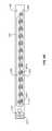
- FIGS. 6A and 6Bare top views of two versions of the printed circuit board used to implement the Powered Rail 24 ;
- FIG. 6Cis an exploded view of the printed circuit board used to implement the Powered Rail 24 ;
- FIGS. 7A and 7Billustrate the details of the Powered Rail 24 electrical interconnection;
- FIGS. 8A-8Care illustrations of the typical mechanical interconnection and electrical interconnection of a Power-Consuming Accessory to the Handguard 23 and Powered Rail 24 .
- the Powered Rail 24comprises one or more Printed Circuit Board Assemblies ( 60 - 1 to 60 - 4 ) which are mounted in the apertures formed in a successive plurality of locking slots on the Powered Rails 24 to carry power to power-consuming accessories which are mounted on the Powered Rail 24 at various locations.
- the Printed Circuit Boards ( 60 - 1 to 60 - 4 )are soldered to electrically conductive busses 72 , 74 .
- a conductive pin connectorincludes a terminal portion at one end which is pressed into the mating hole (not shown) in the interconnect electrical bus 72 .
- Retaining clips 71are manufactured from resilient metallic spring material, which are anchored on the upper rail connector 75 and a clamp hook feature of the retaining clip 71 is used to securely hold the lower rail connector 76 by engaging features formed on the lower rail connector 76 .
- FIG. 7Billustrates the retaining clips 71 and electrically conductive busses 72 typically encapsulated in an insulative protective coating. The connector is removable and can be mounted easily through the retaining clips 71 which provide positive retention and a means of securing the connector halves. Mated connector pairs have tab features which captivate the clips.
- FIGS. 6A and 6Billustrate the architecture of the printed circuit board used to implement the Printed Circuit Board 62 where remote power is applied via the positive connector contact 61 P and the negative connector contact 61 N.
- the poweris routed by the electrical traces on the Printed Circuit Board 62 .
- the positive current from positive connector contact 61 Pis routed to the center of the Printed Circuit Board switch (for example, 63 - 5 ) where it is switched via operation of the switch 64 (shown in FIG. 6C ) to contact 63 P- 5
- the negative current from the negative connector contact 61 Nis routed to the negative bus 62 N or negative bus contact pads (for example, 62 N 3 ).
- FIGS. 6A and 6Bthere are thirteen positive contacts 62 P- 1 to 62 P- 13 (only several of which are numbered on the figures to avoid clutter).
- FIG. 6Aa continuous negative bus 62 N is provided as the other power source connection.
- FIG. 6Bthe negative power source connections are provided by thirteen individual negative bus contact pads 62 N- 1 to 62 N- 13 (only several of which are numbered on the figures to avoid clutter).
- points of attachmenttypically comprising notches 64 A and 64 B, which are used to secure the printed circuit board in place in the corresponding slot of the Powered Rail 24 via a pin clip arrangement.
- the positive 62 P- 3 , 62 P- 8 (for example) and negative 62 N- 3 , 62 N- 8 contactscan be continuously powered, especially in the case where only one set of contacts is provided, or can be switch activated by metallic snap dome switches 63 - 3 , 63 - 8 which are placed over positive common 94 (as shown in FIG. 10 ) and are in electrical contact with the accessory positive switched contact 62 P- 3 , 62 P- 8 .
- the metallic snap dome switchhas a pair of conductive contacts which are normally in the open mode; when the cover of the metallic snap dome switch is depressed via a projection on the exterior surface of the power-consuming accessory which is mounted on the Powered Rail 24 juxtaposed to the metallic snap dome switch, these contacts mate and provide an electrical connection between positive common 94 and a positive switched contact 62 P as shown in FIG. 10 .
- the metallic snap dome switchis a well-known component and consists of a curved metallic dome that spans two conductors (positive common 94 and a positive switched contact 62 P (as shown in FIG. 10 ) such that when the dome is depressed, it snaps downward to electrically bridge the two conductors.
- the accessory positive switched contact 62 P and the accessory common negative bus contact pad 62 Nare both implemented using the Low Reflectivity Contact described below.
- FIG. 6Cillustrates an exploded view of the power distribution Printed Circuit Board assembly where a non-conductive layer 65 prevents the metal weapon Rail from electrically shorting the power distribution Printed Circuit Board 62 .
- Spacer layer 63is a non-conductive element which holds the snap dome switches in place so they do not move laterally during assembly.
- Metallic snap dome switches 68provide the electrical switching action to mounted rail accessories.
- Top cover layer 65provides environmental protection to the Printed Circuit Board 62 and the metallic snap dome switches 64 when the aforementioned layers are assembled.
- FIGS. 8A-8Care illustrations of the typical mechanical interconnection and electrical interconnection of a power-consuming accessory (such as flashlight 8 ) to the Handguard 23 and Powered Rail 24 .
- the perspective view of FIG. 8Ashows how the Powered Accessory Mounting 25 attaches the power-consuming accessory to the Powered Rail 24 and consists of a rail grabber 301 , spring contacts 302 , spring plungers 303 , and face seals 304 .
- the spring plungers 303depress the snap-dome switches on the Powered Rail 24
- the spring contacts 302provide electrical contact with the fixed electrical bus contacts 62 M and 62 P-* on the Powered Rail 24 Printed Circuit Board assembly
- the face seals 304provide environmental protection.
- FIGS. 8B and 8Care cutaway end views of the interconnection of a power-consuming accessory to the Handguard 23 and Powered Rail 24 .
- the power-consuming accessory and associated Powered Accessory Mounting ACCare mechanically attached to the Handguard 23 in well-known fashion (via screw clamp SC shown here).
- the Powered Accessory Mounting ACCincludes a pair of spring contact pins 82 A, 82 B which contact corresponding Low Reflectivity Contacts 62 N and 62 P which are mounted on Printed Circuit Board 60 - 3 .
- the Powered Accessory Mounting ACCincludes a spring plunger 303 which contacts corresponding metallic snap dome switch 64 which is mounted on Printed Circuit Board 60 - 3 .
- An ideal electrical connectorhas a low contact resistance and high insulation value. It is resistant to vibration, water, oil, and pressure. It is easily mated/unmated, unambiguously preserves the orientation of connected circuits, reliable, and carries one or multiple circuits. Desirable properties for a connector also include easy identification, compact size, rugged construction, durability (capable of many connect/disconnect cycles), rapid assembly, simple tooling, and low cost. No single electrical connector has all of the ideal properties. The proliferation of types of electrical connectors is a reflection of the differing importance placed on the design factors.
- the selection of low resistivity metals to construct the contactcontradicts with the goal of achieving low light reflectivity.
- goldis highly conductive and makes an excellent choice for a contact, but has a high light reflectivity. If coatings are applied to a gold contact to reduce the light reflectivity, the resistivity of the contact is increased and the coatings quickly wear off in a hostile ambient environment where there are many connect/disconnect cycles. Mechanically modifying the surface of the gold to reduce the flat light reflecting plane presented to incoming visible light also reduces the conductivity of the contact and fails to achieve adequate reductions in light reflectivity reduction. Similar problems are encountered with attempts to alloy gold with other metals.
- FIG. 9is a schematic of loose mesh contact disks, plain side 90 up and solder side 91 up, which are used to implement the Low Reflectivity Contact; and FIG. 10 is an illustration of a Low Reflectivity Contact 92 soldered to a Printed Circuit Board 93 .
- the Low Reflectivity Contact 92consists of one Contact of a Contact Pair and is manufactured from a suitable material, with one example being a 400 mesh, alloy 304 Stainless Steel which is woven with a 0.001′′ thick wire of cylindrical cross-section. The mesh is cut into the desired shape, such as a circle, and one side of the mesh is tinned with solder and soldered onto a Printed Circuit Board (PCB) which is designed to carry power from a power source to the electrical contacts.
- the other Contact of the Contact Pairconsists of a spring loaded contact pin (or lever or any other mechanism to make mechanical contact with the Low Reflectivity Contact) to touch the mesh surface of the Low Reflectivity Contact to provide an electrical connection.
- the selection of a wire mesh to implement the electrical contactsis dictated by the need to provide a low light reflectivity characteristic for the exposed electrical contacts.
- the need for low light reflectivityis important in certain applications, such as military weapons.
- the Low Reflectivity Contactprovides a target of dimensions which enable the mating Contact of the Contact Pair to complete the circuit connection without the need for precise spatial three-dimensional alignments of the two Contacts of the Contact Pair.
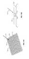
- FIGS. 11A and 11Bare illustrations of the light reflectivity geometry of the Low Reflectivity Contact.
- the Low Reflectivity Contacttypically comprises a mesh grid 1101 formed of a matrix of electrical wires 1104 and 1105 which are interconnected to form a matrix with apertures 1103 formed in the surface thereof.
- the mesh grid 1101can be formed of a sheet of electrically conductive material with apertures 1103 formed in the surface thereof.
- Incident visible light 1102(as well as other wavelengths of light) is dispersed by the electric wires 1104 , 1105 ; and only a small fraction of the incident visible light passes through the apertures 1103 of the mesh grid 1101 to the underlying surface 1106 , which is typically a conductive pad on the surface of the Printed Circuit Board.
- the incident light 1107 that passes through the apertures 1103is reflected 1108 off surface 1106 and strikes the bottom surface of the mesh grid 1101 . Therefore, the only way the incident visible light is retransmitted back out of the Low Reflectivity Contacts is for the reflected beam 1108 to pass through an aperture 1103 .
- the size of the apertures and the light reflection pathcan be managed to substantially eliminate the reflection of visible light off the Low Reflectivity Contact.
- the Low Reflectivity Contactminimizes light reflectivity by the use of a conductive mesh grid which is attached to an underlying conductive surface.
- the conductive mesh gridcomprises a substantially planar structure, typically a matrix of interconnected wires with apertures formed between the intersecting wires, and is used to form the outer surface of the electrical contact.
- the weave density, weave geometry, and wire diameter of the conductive mesh gridmaximizes the attenuation of reflected light in the visible spectrum, yet maintains high electrical conductivity and a lack of sensitivity to contamination via the choice of materials used to implement the Low Reflectivity Contact.
- FIGS. 12A-12Iare illustrations of details of the butt stock version of the Weapon Accessory Power Source.
- the battery 33can be mounted on the bottom side of the buffer tube/receiver extension 34 by the use of a dovetail slide guide rail 1214 that extends longitudinally into the buffer tube/receiver extension 34 and mates with the dovetail slide channel 1215 ( FIG. 12E ) formed on the side of the battery pack 33 .
- the battery pack 33when seated in the buffer tube/receiver extension 34 , has its power connection 1218 engage the mating electrical connection of rifle power socket 1216 thereby to provide power to the Powered Rail 24 as shown in FIGS. 12F and 12I and as described herein.
- Detent balls 1212shown in FIG. 12C , operate with pivot pin 1211 temporarily holding the cam lever 1208 in a preset position extended away from butt stock 21 when the cam lever 1208 is rotated on pivot pin 1211 thereby to enable the installation of the battery pack 33 into buffer tube/receiver extension 34 .
- detent balls 1212provide a lock to prevent accidental release of the battery 33 from the buffer tube/receiver extension 34 .
- the adjustable butt stock 21can slide along the buffer tube/receiver extension 34 and be set in any of a number of predetermined positions.
- the adjustable butt stock 21has both locking and quick release mechanisms 1209 , as shown in FIG. 12A , which provide the user with the ability to lock the adjustable butt stock 21 on the buffer tube/receiver extension 34 in any of a plurality of predetermined positions which thereby enables the user to adjust the overall length of the weapon 2 .
- Indexing notches 1202are provided on either side of a slide guide ramp 1201 , which extends along the length of the buffer tube/receiver extension 34 and rides on a mating slide guide slot 1207 .
- Clevis pin 1204 A and the associated retaining ring 1206is used to secure the release lever 1205 to the latch arm 1203 and the butt stock 21
- clevis pin 1204 Battaches torsion spring 1219 to latch arm 1203 to provide a spring force to hold latch arm 1203 away from the bottom side of butt stock 21
- Operation of the release lever 1205compresses torsion spring 1219 and causes the latch arm 1203 to rotate on clevis pin 1204 A thereby to disengage the latch arm 1203 from the one of indexing notches 1202 in which it presently is seated, thereby enabling the user to slide the adjustable butt stock 21 in the desired direction on the buffer tube/receiver extension 34 .
- a release stop tab 1220is provided to limit the travel of the adjustable butt stock 21 on the buffer tube/receiver extension 34 . Release of the release lever 1205 causes the torsion spring 1219 to force the latch arm 1203 to rotate around clevis pin 1204 A in an upward direction into an indexing notch 1202 , thereby locking the butt stock 21 in position.
- the battery pack 33consists of a pair of exposed electrode terminals, positive 1218 P and negative 1218 N, as well as internal battery spring terminals 1223 which serve to engage one end of a plurality of replaceable battery cells 1221 .
- a removable battery cover 1217secures the battery cells 1221 in the battery housing compartment 1222 .
- the removable battery cover 1217consists of the cover plate 1217 P, spring terminals 1223 , rubber washer bumpers 1224 , O-ring gaskets 1228 , and a cover screw mechanism 1225 which opens and closes the battery compartment.
- the cover screw mechanism 1225includes a threaded screw which extends through the battery cover 1217 and a threaded locking nut 1227 having an internal mount feature on the battery housing 1221 .
- Alternative power source configurationsinclude the use of a battery pack 1302 attached to the bottom of the pistol grip 105 as shown in FIG. 13B .
- Another power source configurationis to mount the battery pack 1301 in the fore-grip 105 as shown in FIG. 13A .
- the battery pack 1301can be designed to fit into a mount that replaces the lower fore-grip 105 .
- An additional method, illustrated in FIGS. 14A-14Centails mounting the battery pack 1401 - 1403 directly to the handguard 23 where it electrically connects to the associated Powered Rail 24 , where the battery pack 1401 - 1403 delivers power to the Powered Rail 24 through the contacts as described above. Connection to the Powered Rail 24 can also be used, as shown in FIGS.
- the soldier 1500carries the battery pack 1502 as part of their equipment, which includes radio 1504 and communication microphone 1503 .
- This last configurationcan also be used to provide a recharging capability to the battery pack, wherever mounted, where the Powered Rail 24 is used as an interface to a recharging system.
Landscapes
- Engineering & Computer Science (AREA)
- General Engineering & Computer Science (AREA)
- Charge And Discharge Circuits For Batteries Or The Like (AREA)
- Toys (AREA)
Abstract
Description
- Use of a single compact power source,
- Significant reduction in the weight of the accessory/power source system,
- By moving mass rearward, the time to bring the weapon to point is reduced, as well as the time needed to “stop” the muzzle when the target is acquired.
- Compatibility with the existing Picatinny Rail for mounting accessories,
- Performance reliability, and
- Inexpensive to manufacture.
- Battery Pack,
- Power Distribution System,
- Handguard (optional),
- Powered Rail, and
- Power-Consuming Accessory Mounting.
Butt Stock 21 with Battery Pack33 (shown inFIG. 3A );Power Distribution System 22;- Handguard23 (optional);
- Powered
Rail 24; and - Powered Accessory Mounting25 (shown in
FIG. 8A ).
Claims (17)
Priority Applications (2)
| Application Number | Priority Date | Filing Date | Title |
|---|---|---|---|
| US13/075,857US8397418B2 (en) | 2009-01-16 | 2011-03-30 | System for providing electrical power to accessories mounted on the powered |
| US13/845,379US9285185B2 (en) | 2009-01-16 | 2013-03-18 | System for providing electrical power to accessories mounted on the powered rail of a weapon |
Applications Claiming Priority (16)
| Application Number | Priority Date | Filing Date | Title |
|---|---|---|---|
| US14524809P | 2009-01-16 | 2009-01-16 | |
| US14521109P | 2009-01-16 | 2009-01-16 | |
| US14522209P | 2009-01-16 | 2009-01-16 | |
| US14523209P | 2009-01-16 | 2009-01-16 | |
| US14522809P | 2009-01-16 | 2009-01-16 | |
| US14521609P | 2009-01-16 | 2009-01-16 | |
| US18325009P | 2009-06-02 | 2009-06-02 | |
| US18325809P | 2009-06-02 | 2009-06-02 | |
| US12/689,430US20100192447A1 (en) | 2009-01-16 | 2010-01-19 | Rifle accessory rail, communication, and power transfer system |
| US12/689,439US20100180485A1 (en) | 2009-01-16 | 2010-01-19 | Rifle accessory rail, communication, and power transfer system - power distribution |
| US12/689,438US8402683B2 (en) | 2009-01-16 | 2010-01-19 | Rifle accessory rail, communication, and power transfer system-battery pack |
| US12/689,440US8448368B2 (en) | 2009-01-16 | 2010-01-19 | Rifle accessory rail, communication, and power transfer system—rail contacts |
| US12/689,437US20100192443A1 (en) | 2009-01-16 | 2010-01-19 | Rifle accessory rail, communication, and power transfer system - communication |
| US12/689,436US10215529B2 (en) | 2009-01-16 | 2010-01-19 | Accessory mount for rifle accessory rail, communication, and power transfer system—accessory attachment |
| US12/791,460US8141288B2 (en) | 2009-01-16 | 2010-06-01 | Rugged low light reflectivity electrical contact |
| US13/075,857US8397418B2 (en) | 2009-01-16 | 2011-03-30 | System for providing electrical power to accessories mounted on the powered |
Related Parent Applications (1)
| Application Number | Title | Priority Date | Filing Date |
|---|---|---|---|
| US12/791,460Continuation-In-PartUS8141288B2 (en) | 2009-01-16 | 2010-06-01 | Rugged low light reflectivity electrical contact |
Related Child Applications (1)
| Application Number | Title | Priority Date | Filing Date |
|---|---|---|---|
| US13/845,379ContinuationUS9285185B2 (en) | 2009-01-16 | 2013-03-18 | System for providing electrical power to accessories mounted on the powered rail of a weapon |
Publications (2)
| Publication Number | Publication Date |
|---|---|
| US20110283585A1 US20110283585A1 (en) | 2011-11-24 |
| US8397418B2true US8397418B2 (en) | 2013-03-19 |
Family
ID=44971238
Family Applications (2)
| Application Number | Title | Priority Date | Filing Date |
|---|---|---|---|
| US13/075,857Expired - Fee RelatedUS8397418B2 (en) | 2009-01-16 | 2011-03-30 | System for providing electrical power to accessories mounted on the powered |
| US13/845,379ActiveUS9285185B2 (en) | 2009-01-16 | 2013-03-18 | System for providing electrical power to accessories mounted on the powered rail of a weapon |
Family Applications After (1)
| Application Number | Title | Priority Date | Filing Date |
|---|---|---|---|
| US13/845,379ActiveUS9285185B2 (en) | 2009-01-16 | 2013-03-18 | System for providing electrical power to accessories mounted on the powered rail of a weapon |
Country Status (1)
| Country | Link |
|---|---|
| US (2) | US8397418B2 (en) |
Cited By (38)
| Publication number | Priority date | Publication date | Assignee | Title |
|---|---|---|---|---|
| US20070144051A1 (en)* | 2005-12-22 | 2007-06-28 | Larry Moore | Reference beam generating apparatus |
| US20110225867A1 (en)* | 2008-10-10 | 2011-09-22 | Moore Larry E | Light-assisted sighting devices |
| US20130191967A1 (en)* | 2012-01-31 | 2013-08-01 | Angel 7 Industries, Llc | Accessory Platform for a Helmet |
| US8627591B2 (en) | 2008-09-05 | 2014-01-14 | Larry Moore | Slot-mounted sighting device |
| US8696150B2 (en) | 2011-01-18 | 2014-04-15 | Larry E. Moore | Low-profile side mounted laser sighting device |
| US20140115936A1 (en)* | 2012-10-26 | 2014-05-01 | Ra Brands, L.L.C. | Upper receiver and hand guard with cable routing guide |
| US8813411B2 (en) | 2008-10-10 | 2014-08-26 | P&L Industries, Inc. | Gun with side mounting plate |
| US8844189B2 (en) | 2012-12-06 | 2014-09-30 | P&L Industries, Inc. | Sighting device replicating shotgun pattern spread |
| US20140360077A1 (en)* | 2013-03-27 | 2014-12-11 | Craig M. Miller | Powered tactical rail (aka picatinny rail) system and method of using the same |
| US9170079B2 (en) | 2011-01-18 | 2015-10-27 | Larry E. Moore | Laser trainer cartridge |
| US20150316348A1 (en)* | 2014-02-17 | 2015-11-05 | Larry E. Moore | Front-grip lighting device |
| US9250035B2 (en) | 2013-03-21 | 2016-02-02 | Kms Consulting, Llc | Precision aiming system for a weapon |
| US9297614B2 (en) | 2013-08-13 | 2016-03-29 | Larry E. Moore | Master module light source, retainer and kits |
| US9328980B1 (en)* | 2013-10-31 | 2016-05-03 | Jason William Doto | Receiver link separator |
| US20160327371A1 (en)* | 2015-05-04 | 2016-11-10 | Wilcox Industries Corp. | Powered accessory platform for weapon |
| US9644826B2 (en) | 2014-04-25 | 2017-05-09 | Larry E. Moore | Weapon with redirected lighting beam |
| WO2017127298A1 (en)* | 2016-01-18 | 2017-07-27 | Wilcox Industries Corp. | Modular powered platform for weapon |
| US9829280B1 (en) | 2016-05-26 | 2017-11-28 | Larry E. Moore | Laser activated moving target |
| US10066899B2 (en)* | 2013-09-18 | 2018-09-04 | Craig B. Simpson | Modular attachment system for gun stock |
| US10132595B2 (en) | 2015-03-20 | 2018-11-20 | Larry E. Moore | Cross-bow alignment sighter |
| US20190049221A1 (en)* | 2017-07-20 | 2019-02-14 | Trent Zimmer | Firearm accessory electrical distribution system |
| US10209030B2 (en) | 2016-08-31 | 2019-02-19 | Larry E. Moore | Gun grip |
| US10209033B1 (en) | 2018-01-30 | 2019-02-19 | Larry E. Moore | Light sighting and training device |
| US20190226809A1 (en)* | 2018-01-22 | 2019-07-25 | Crimson Trace Corporation | Sight for firearm |
| US20190226810A1 (en)* | 2018-01-22 | 2019-07-25 | Rade Tecnologías, S.L. | Weapon Communication Method and System |
| US10436553B2 (en) | 2014-08-13 | 2019-10-08 | Crimson Trace Corporation | Master module light source and trainer |
| US10436538B2 (en) | 2017-05-19 | 2019-10-08 | Crimson Trace Corporation | Automatic pistol slide with laser |
| US10458754B2 (en)* | 2017-05-15 | 2019-10-29 | T-Worx Holdings, LLC | System and method for networking firearm-mounted devices |
| US10532275B2 (en) | 2012-01-18 | 2020-01-14 | Crimson Trace Corporation | Laser activated moving target |
| US10914548B2 (en) | 2017-05-15 | 2021-02-09 | T-Worx Holdings, LLC | Power system for a firearm |
| USD947979S1 (en)* | 2019-10-10 | 2022-04-05 | T-Worx Holdings, LLC | Electrical contact strip for a powered rail |
| US11320244B2 (en) | 2018-07-02 | 2022-05-03 | Alex Verjovsky | Rifle with laser and illuminator system integrated into rail |
| US20230023146A1 (en)* | 2019-12-11 | 2023-01-26 | Fn Herstal S.A. | Mounting rail for firearm |
| US20230143306A1 (en)* | 2009-01-16 | 2023-05-11 | T-Worx Holdings, LLC | Accessory mount for rifle accessory rail, communication, and power transfer system - accessory attachment |
| US11716807B2 (en)* | 2021-12-09 | 2023-08-01 | Fieldpiece Instruments, Inc. | Power and communication handguard |
| US11808537B2 (en) | 2018-06-06 | 2023-11-07 | Wilcox Industries Corp. | Weapon system with operator identification |
| US20250003712A1 (en)* | 2023-06-28 | 2025-01-02 | Wilcox Industries Corp. | Power and data interface for weapon accessory mounting rail |
| US20250085080A1 (en)* | 2023-09-13 | 2025-03-13 | Wilcox Industries Corp. | Power and data retrofit for weapon accessory rail |
Families Citing this family (43)
| Publication number | Priority date | Publication date | Assignee | Title |
|---|---|---|---|---|
| US8656622B2 (en) | 2007-10-11 | 2014-02-25 | Ashbury International Group, Inc. | Tactical firearm systems and methods of manufacturing same |
| US9459060B2 (en) | 2009-10-05 | 2016-10-04 | Colt's Manufacturing Ip Holding Company Llc | Modular firearm |
| EP2486362B1 (en) | 2009-10-05 | 2019-06-26 | Colt's Manufacturing IP Holding Company LLC | Modular automatic or semi-automatic rifle |
| WO2011079233A2 (en)* | 2009-12-23 | 2011-06-30 | Reset, Inc. | Communication and power distribution system and segmented rail adapter |
| US10337834B2 (en) | 2010-01-15 | 2019-07-02 | Colt Canada Ip Holding Partnership | Networked battle system or firearm |
| US10470010B2 (en) | 2010-01-15 | 2019-11-05 | Colt Canada Ip Holding Partnership | Networked battle system or firearm |
| US10477618B2 (en) | 2010-01-15 | 2019-11-12 | Colt Canada Ip Holding Partnership | Networked battle system or firearm |
| US10477619B2 (en) | 2010-01-15 | 2019-11-12 | Colt Canada Ip Holding Partnership | Networked battle system or firearm |
| US9823043B2 (en) | 2010-01-15 | 2017-11-21 | Colt Canada Ip Holding Partnership | Rail for inductively powering firearm accessories |
| US9921028B2 (en) | 2010-01-15 | 2018-03-20 | Colt Canada Ip Holding Partnership | Apparatus and method for powering and networking a rail of a firearm |
| USD674859S1 (en)* | 2010-10-05 | 2013-01-22 | Colt Defense, Llc | Firearm |
| US8490313B2 (en)* | 2011-01-18 | 2013-07-23 | Prototype Productions Incorporated Ventures Two, Llc | Apparatus for mounting accessories on the accessory rail of a weapon |
| DK3165868T3 (en) | 2011-02-15 | 2018-11-26 | Colt Canada Ip Holding Partnership | Apparatus and method for inductive power supply and network connection of a firearm's rail |
| USD682383S1 (en)* | 2011-07-19 | 2013-05-14 | Joshua A. Underwood | Selector indicator for firearm receiver |
| KR20150027025A (en)* | 2011-12-06 | 2015-03-11 | 레이저 에너제틱스, 인크. | Weapon-mountable non-lethal optical security device |
| US8776422B2 (en)* | 2012-01-24 | 2014-07-15 | Prototype Productions, Inc. | Communication and control of accessories mounted on the powered rail of a weapon |
| CA2881982C (en) | 2012-08-16 | 2020-10-13 | Colt Canada Corporation | Apparatus and method for powering and networking a rail of a firearm |
| USD733830S1 (en)* | 2014-02-04 | 2015-07-07 | Ati Ip, Llc | Contoured pistol grip |
| USD733829S1 (en)* | 2014-02-04 | 2015-07-07 | Ati Ip, Llc | Contoured pistol grip |
| US9784536B2 (en)* | 2014-04-12 | 2017-10-10 | Jason William Boswell | Weapon light mount |
| US9400156B2 (en)* | 2014-10-03 | 2016-07-26 | Ronald Michael Lamb | Storage compartment |
| WO2016118218A1 (en)* | 2015-01-19 | 2016-07-28 | Toole Ronald L | Laser aiming and illumination device for a weapons platform |
| US9574846B2 (en)* | 2015-03-05 | 2017-02-21 | George Huang | Receiver and collapsible buttstock for a firearm |
| US9766034B2 (en)* | 2015-03-05 | 2017-09-19 | George Huang | Bolt-on collapsible stock assembly for a firearm |
| US9777985B2 (en) | 2015-11-13 | 2017-10-03 | Magpul Industries Corp. | Firearm accessory attachment system |
| ITUB20160173A1 (en)* | 2016-01-27 | 2017-07-27 | Fabbrica Darmi Pietro Beretta S P A | GUIDE FOR FIRE WEAPONS |
| US10415932B1 (en)* | 2016-07-22 | 2019-09-17 | Knight Vision LLLP | Adjustable weapon-based mount for a monocular night-vision goggle |
| US20190222771A1 (en) | 2016-10-14 | 2019-07-18 | Laser Aiming Systems Corporation | Gun-mounted recording device |
| US11306987B2 (en) | 2016-10-14 | 2022-04-19 | Laser Aiming Systems Corporation | Gun-mounted recording device with auto on |
| US10655928B2 (en)* | 2017-06-10 | 2020-05-19 | Serious Simulations, Llc | Integrated rechargeable power and power management technology for individual weapon mounted electronic devices |
| US10408570B2 (en) | 2018-01-19 | 2019-09-10 | CQB Optics, LLC | Side receiving mounted laser aiming and illumination device for firearms |
| WO2021107827A1 (en)* | 2019-11-25 | 2021-06-03 | Husqvarna Ab | A hand-held electrically powered work tool |
| US11609065B2 (en)* | 2020-02-13 | 2023-03-21 | Charles Raymond | Multi-adjustable firearm stock |
| US10876814B1 (en)* | 2020-03-20 | 2020-12-29 | Scott Dean Visser | Storage container for mounting on firearms |
| WO2021203032A1 (en) | 2020-04-02 | 2021-10-07 | T-Worx Holdings, LLC | High-throughput data communication for rail-mounted devices |
| US11555669B2 (en)* | 2020-06-23 | 2023-01-17 | Sellmark Corporation | Firearm sight with modular interchangeable hoods |
| US12130121B1 (en) | 2020-07-21 | 2024-10-29 | Laser Aiming Systems Corporation | Data redundancy and hardware tracking system for gun-mounted recording device |
| US12173992B1 (en) | 2020-07-21 | 2024-12-24 | Laser Aiming Systems Corporation | Gun mounted recording device with quick release battery |
| US20220325968A1 (en)* | 2021-04-12 | 2022-10-13 | T-Worx Holdings, LLC | Electrical connector for a firearm |
| US20220341697A1 (en)* | 2021-04-21 | 2022-10-27 | T-Worx Holdings, LLC | Electrical power source for a firearm |
| US20230110575A1 (en)* | 2021-10-08 | 2023-04-13 | Francisco Chang Cinco | Firearms Cable Fastening Device |
| US12152857B2 (en)* | 2021-11-16 | 2024-11-26 | Strike IP, LLC | Firearm handguard cable organizer |
| USD991367S1 (en)* | 2022-05-18 | 2023-07-04 | Chuzhen Cai | Toy gun |
Citations (37)
| Publication number | Priority date | Publication date | Assignee | Title |
|---|---|---|---|---|
| US4533980A (en) | 1982-06-21 | 1985-08-06 | Hayes Lawrence S | Luminous gun sighting system |
| US5033219A (en)* | 1990-02-06 | 1991-07-23 | Emerging Technologies, Inc. | Modular laser aiming system |
| US5142806A (en) | 1991-09-23 | 1992-09-01 | Swan Richard E | Universal receiver sleeve |
| US5360949A (en)* | 1993-06-30 | 1994-11-01 | Northern Telecom Limited | Printed circuit board |
| US5826363A (en) | 1997-07-10 | 1998-10-27 | Knights Armament Company | Rail adapter handguard systems for firearms |
| US6237271B1 (en) | 1996-07-23 | 2001-05-29 | Colt's Manufacturing Company, Inc. | Firearm with safety system having a communication package |
| US6925744B2 (en)* | 2003-05-13 | 2005-08-09 | Abrams Airborne Manufacturing, Inc. | Modular firearm buttstock |
| US20050241206A1 (en) | 2004-03-22 | 2005-11-03 | Wilcox Industries Corporation | Hand grip apparatus for firearm |
| US7144830B2 (en)* | 2002-05-10 | 2006-12-05 | Sarnoff Corporation | Plural layer woven electronic textile, article and method |
| US7243454B1 (en)* | 2005-04-02 | 2007-07-17 | Tango Down, Llc | Integrated pressure switch pocket for a vertical fore grip |
| US20080040965A1 (en) | 1998-07-02 | 2008-02-21 | Solinsky Kenneth S | Auxiliary device for a weapon and attachment thereof |
| US20080170838A1 (en)* | 2007-01-11 | 2008-07-17 | Wilcox Industries Corp. | Head-mounted video recording system |
| US20080190002A1 (en)* | 2007-02-12 | 2008-08-14 | Steve Hines | Modular rail cover |
| US7421818B2 (en) | 2006-02-04 | 2008-09-09 | Lasermax, Inc. | Firearm mount with embedded laser sight |
| US20090044439A1 (en)* | 2007-08-16 | 2009-02-19 | Breaching Technologies, Inc. | Tactical foregrip assembly |
| US7525203B1 (en)* | 2005-08-11 | 2009-04-28 | Jeffrey Racho | Back-up electric power generator for electronic components attached to automatic firearms |
| US7584569B2 (en) | 2005-08-19 | 2009-09-08 | Lasermax, Inc. | Target illuminating assembly having integrated magazine tube and barrel clamp with laser sight |
| US20090255160A1 (en)* | 2008-04-11 | 2009-10-15 | James Summers | Weapon control device |
| US7627975B1 (en) | 2007-02-12 | 2009-12-08 | Steve Hines | Electrified handguard |
| US7640690B2 (en)* | 2006-07-27 | 2010-01-05 | Steve Hines | Stock interface |
| US20100031552A1 (en) | 2008-07-16 | 2010-02-11 | Lasermax, Inc. | Firearm assembly |
| US20100083553A1 (en) | 2008-10-03 | 2010-04-08 | Nanomaterials Discovery Corporation | Firearm Having Central Power Source and Integrated Data Bus to both Power and Control Multiple Accessories |
| US20100192444A1 (en)* | 2009-01-16 | 2010-08-05 | Prototype Productions, Inc. | Rifle accessory rail, communication, and power transfer system - rail contacts |
| US20100192446A1 (en) | 2009-02-05 | 2010-08-05 | Rubik Darian | Mounting rail |
| US20100192443A1 (en)* | 2009-01-16 | 2010-08-05 | Prototype Productions, Inc. | Rifle accessory rail, communication, and power transfer system - communication |
| US20100192448A1 (en) | 2009-02-05 | 2010-08-05 | Rubik Darian | Mounting rail |
| US20100218410A1 (en)* | 2009-01-16 | 2010-09-02 | Prototype Productions, Inc. | Accessory mount for rifle accessory rail, communication, and power transfer system - accessory attachment |
| US20100242332A1 (en) | 2004-03-22 | 2010-09-30 | Teetzel James W | Hand grip apparatus for firearm |
| US7818910B2 (en)* | 2004-09-29 | 2010-10-26 | The United States Of America As Represented By The Secretary Of The Army | Weapon integrated controller |
| US20110000120A1 (en) | 2006-09-28 | 2011-01-06 | John Thompson | Power rail system |
| US7866083B2 (en) | 2006-11-01 | 2011-01-11 | Wilcox Industries Corp. | Modular flashlight apparatus for firearm |
| US20110010979A1 (en) | 2009-07-16 | 2011-01-20 | Lasermax, Inc. | Mounting rail assembly for firearms |
| US20110126622A1 (en)* | 2009-05-29 | 2011-06-02 | Turner Brian P | Apparatus and method for monitoring projectile emission and charging an energy storage device |
| US20110162251A1 (en)* | 2006-02-04 | 2011-07-07 | Houde-Walter William R | Firearm mount with embedded sight |
| US7975419B2 (en)* | 2009-02-05 | 2011-07-12 | Rubik Darian | Mounting rail |
| US20110173865A1 (en)* | 2010-01-15 | 2011-07-21 | Colt Canada Corporation | Rail for inductively powering firearm accessories |
| US8001715B2 (en)* | 2005-04-26 | 2011-08-23 | Tactical Devices, Inc. | Illumination apparatus implementing non-lethal weapon |
Family Cites Families (14)
| Publication number | Priority date | Publication date | Assignee | Title |
|---|---|---|---|---|
| US4777861A (en) | 1987-01-16 | 1988-10-18 | Recon/Optical, Inc. | Missile aiming sight |
| US5669174A (en) | 1993-06-08 | 1997-09-23 | Teetzel; James W. | Laser range finding apparatus |
| US5822905A (en) | 1994-02-23 | 1998-10-20 | Teetzel; James W. | Firearm hand grips for controlling an electronic module |
| US6163131A (en) | 1998-04-02 | 2000-12-19 | The Procter & Gamble Company | Battery having a built-in controller |
| US6622416B2 (en) | 2001-01-04 | 2003-09-23 | Surefire, Llc | Target and navigation illuminators for firearms |
| US6490822B1 (en) | 2001-03-09 | 2002-12-10 | Richard E. Swan | Modular sleeve |
| US6618976B1 (en) | 2001-12-10 | 2003-09-16 | Richard E. Swan | Drop-in laser |
| US6931775B2 (en) | 2002-06-05 | 2005-08-23 | Lockheed Martin Corporation | Remote control module for a vehicle |
| KR101333023B1 (en) | 2006-01-16 | 2013-11-26 | 코닌클리케 필립스 엔.브이. | Lamp module and lighting device comprising such a lamp module |
| TWM296364U (en) | 2006-03-20 | 2006-08-21 | Asia Optical Co Inc | Firearms aiming and photographing compound apparatus |
| EP2018721A4 (en) | 2006-05-12 | 2012-08-08 | Irobot Corp | Method and device for controlling a remote vehicle |
| US8464451B2 (en) | 2006-05-23 | 2013-06-18 | Michael William McRae | Firearm system for data acquisition and control |
| US7730820B2 (en) | 2006-07-17 | 2010-06-08 | Anthrotronix, Inc. | Mounted isometric controller |
| US8091265B1 (en) | 2007-01-10 | 2012-01-10 | Wilcox Industries Corp. | Floating rail system for firearm |
- 2011
- 2011-03-30USUS13/075,857patent/US8397418B2/ennot_activeExpired - Fee Related
- 2013
- 2013-03-18USUS13/845,379patent/US9285185B2/enactiveActive
Patent Citations (43)
| Publication number | Priority date | Publication date | Assignee | Title |
|---|---|---|---|---|
| US4533980A (en) | 1982-06-21 | 1985-08-06 | Hayes Lawrence S | Luminous gun sighting system |
| US5033219A (en)* | 1990-02-06 | 1991-07-23 | Emerging Technologies, Inc. | Modular laser aiming system |
| US5142806A (en) | 1991-09-23 | 1992-09-01 | Swan Richard E | Universal receiver sleeve |
| US5360949A (en)* | 1993-06-30 | 1994-11-01 | Northern Telecom Limited | Printed circuit board |
| US6237271B1 (en) | 1996-07-23 | 2001-05-29 | Colt's Manufacturing Company, Inc. | Firearm with safety system having a communication package |
| US5826363A (en) | 1997-07-10 | 1998-10-27 | Knights Armament Company | Rail adapter handguard systems for firearms |
| US20080040965A1 (en) | 1998-07-02 | 2008-02-21 | Solinsky Kenneth S | Auxiliary device for a weapon and attachment thereof |
| US7144830B2 (en)* | 2002-05-10 | 2006-12-05 | Sarnoff Corporation | Plural layer woven electronic textile, article and method |
| US6925744B2 (en)* | 2003-05-13 | 2005-08-09 | Abrams Airborne Manufacturing, Inc. | Modular firearm buttstock |
| US20050241206A1 (en) | 2004-03-22 | 2005-11-03 | Wilcox Industries Corporation | Hand grip apparatus for firearm |
| US7841120B2 (en) | 2004-03-22 | 2010-11-30 | Wilcox Industries Corp. | Hand grip apparatus for firearm |
| US7712241B2 (en) | 2004-03-22 | 2010-05-11 | Wilcox Industries Corp. | Hand grip apparatus for firearm |
| US20100242332A1 (en) | 2004-03-22 | 2010-09-30 | Teetzel James W | Hand grip apparatus for firearm |
| US7818910B2 (en)* | 2004-09-29 | 2010-10-26 | The United States Of America As Represented By The Secretary Of The Army | Weapon integrated controller |
| US7464495B2 (en)* | 2005-04-02 | 2008-12-16 | Tango Down, Inc. | Integrated pressure switch pocket for a vertical fore grip |
| US7243454B1 (en)* | 2005-04-02 | 2007-07-17 | Tango Down, Llc | Integrated pressure switch pocket for a vertical fore grip |
| US8001715B2 (en)* | 2005-04-26 | 2011-08-23 | Tactical Devices, Inc. | Illumination apparatus implementing non-lethal weapon |
| US7525203B1 (en)* | 2005-08-11 | 2009-04-28 | Jeffrey Racho | Back-up electric power generator for electronic components attached to automatic firearms |
| US20090108589A1 (en)* | 2005-08-11 | 2009-04-30 | Jeffrey Racho | Back-up electric power generator for electronic components attached to automatic firearms |
| US7584569B2 (en) | 2005-08-19 | 2009-09-08 | Lasermax, Inc. | Target illuminating assembly having integrated magazine tube and barrel clamp with laser sight |
| US7421818B2 (en) | 2006-02-04 | 2008-09-09 | Lasermax, Inc. | Firearm mount with embedded laser sight |
| US20110162251A1 (en)* | 2006-02-04 | 2011-07-07 | Houde-Walter William R | Firearm mount with embedded sight |
| US7640690B2 (en)* | 2006-07-27 | 2010-01-05 | Steve Hines | Stock interface |
| US20110000120A1 (en) | 2006-09-28 | 2011-01-06 | John Thompson | Power rail system |
| US7866083B2 (en) | 2006-11-01 | 2011-01-11 | Wilcox Industries Corp. | Modular flashlight apparatus for firearm |
| US20080170838A1 (en)* | 2007-01-11 | 2008-07-17 | Wilcox Industries Corp. | Head-mounted video recording system |
| US7627975B1 (en) | 2007-02-12 | 2009-12-08 | Steve Hines | Electrified handguard |
| US20080190002A1 (en)* | 2007-02-12 | 2008-08-14 | Steve Hines | Modular rail cover |
| US7562483B2 (en)* | 2007-02-12 | 2009-07-21 | Steve Hines | Modular rail cover |
| US20090044439A1 (en)* | 2007-08-16 | 2009-02-19 | Breaching Technologies, Inc. | Tactical foregrip assembly |
| US7676975B2 (en)* | 2007-08-16 | 2010-03-16 | Breaching Technologies, Inc. | Tactical foregrip assembly |
| US20090255160A1 (en)* | 2008-04-11 | 2009-10-15 | James Summers | Weapon control device |
| US20100031552A1 (en) | 2008-07-16 | 2010-02-11 | Lasermax, Inc. | Firearm assembly |
| US20100083553A1 (en) | 2008-10-03 | 2010-04-08 | Nanomaterials Discovery Corporation | Firearm Having Central Power Source and Integrated Data Bus to both Power and Control Multiple Accessories |
| US20100218410A1 (en)* | 2009-01-16 | 2010-09-02 | Prototype Productions, Inc. | Accessory mount for rifle accessory rail, communication, and power transfer system - accessory attachment |
| US20100192443A1 (en)* | 2009-01-16 | 2010-08-05 | Prototype Productions, Inc. | Rifle accessory rail, communication, and power transfer system - communication |
| US20100192444A1 (en)* | 2009-01-16 | 2010-08-05 | Prototype Productions, Inc. | Rifle accessory rail, communication, and power transfer system - rail contacts |
| US20100192448A1 (en) | 2009-02-05 | 2010-08-05 | Rubik Darian | Mounting rail |
| US20100192446A1 (en) | 2009-02-05 | 2010-08-05 | Rubik Darian | Mounting rail |
| US7975419B2 (en)* | 2009-02-05 | 2011-07-12 | Rubik Darian | Mounting rail |
| US20110126622A1 (en)* | 2009-05-29 | 2011-06-02 | Turner Brian P | Apparatus and method for monitoring projectile emission and charging an energy storage device |
| US20110010979A1 (en) | 2009-07-16 | 2011-01-20 | Lasermax, Inc. | Mounting rail assembly for firearms |
| US20110173865A1 (en)* | 2010-01-15 | 2011-07-21 | Colt Canada Corporation | Rail for inductively powering firearm accessories |
Cited By (59)
| Publication number | Priority date | Publication date | Assignee | Title |
|---|---|---|---|---|
| US8695266B2 (en) | 2005-12-22 | 2014-04-15 | Larry Moore | Reference beam generating apparatus |
| US20070144051A1 (en)* | 2005-12-22 | 2007-06-28 | Larry Moore | Reference beam generating apparatus |
| US8627591B2 (en) | 2008-09-05 | 2014-01-14 | Larry Moore | Slot-mounted sighting device |
| US8813411B2 (en) | 2008-10-10 | 2014-08-26 | P&L Industries, Inc. | Gun with side mounting plate |
| US20110225867A1 (en)* | 2008-10-10 | 2011-09-22 | Moore Larry E | Light-assisted sighting devices |
| US9188407B2 (en) | 2008-10-10 | 2015-11-17 | Larry E. Moore | Gun with side mounting plate |
| US8607495B2 (en) | 2008-10-10 | 2013-12-17 | Larry E. Moore | Light-assisted sighting devices |
| US20230143306A1 (en)* | 2009-01-16 | 2023-05-11 | T-Worx Holdings, LLC | Accessory mount for rifle accessory rail, communication, and power transfer system - accessory attachment |
| US9429404B2 (en) | 2011-01-18 | 2016-08-30 | Larry E. Moore | Laser trainer target |
| US9170079B2 (en) | 2011-01-18 | 2015-10-27 | Larry E. Moore | Laser trainer cartridge |
| US8696150B2 (en) | 2011-01-18 | 2014-04-15 | Larry E. Moore | Low-profile side mounted laser sighting device |
| US9915508B2 (en) | 2011-01-18 | 2018-03-13 | Larry Moore | Laser trainer target |
| US10532275B2 (en) | 2012-01-18 | 2020-01-14 | Crimson Trace Corporation | Laser activated moving target |
| US20130191967A1 (en)* | 2012-01-31 | 2013-08-01 | Angel 7 Industries, Llc | Accessory Platform for a Helmet |
| US8850735B2 (en)* | 2012-10-26 | 2014-10-07 | Ra Brands, L.L.C. | Upper receiver and hand guard with cable routing guide |
| US20140115936A1 (en)* | 2012-10-26 | 2014-05-01 | Ra Brands, L.L.C. | Upper receiver and hand guard with cable routing guide |
| US8844189B2 (en) | 2012-12-06 | 2014-09-30 | P&L Industries, Inc. | Sighting device replicating shotgun pattern spread |
| US9146077B2 (en) | 2012-12-06 | 2015-09-29 | Larry E. Moore | Shotgun with sighting device |
| US9250035B2 (en) | 2013-03-21 | 2016-02-02 | Kms Consulting, Llc | Precision aiming system for a weapon |
| US20140360077A1 (en)* | 2013-03-27 | 2014-12-11 | Craig M. Miller | Powered tactical rail (aka picatinny rail) system and method of using the same |
| US9297614B2 (en) | 2013-08-13 | 2016-03-29 | Larry E. Moore | Master module light source, retainer and kits |
| US10066899B2 (en)* | 2013-09-18 | 2018-09-04 | Craig B. Simpson | Modular attachment system for gun stock |
| US9328980B1 (en)* | 2013-10-31 | 2016-05-03 | Jason William Doto | Receiver link separator |
| US20150316348A1 (en)* | 2014-02-17 | 2015-11-05 | Larry E. Moore | Front-grip lighting device |
| US9841254B2 (en) | 2014-02-17 | 2017-12-12 | Larry E. Moore | Front-grip lighting device |
| US9341440B2 (en)* | 2014-02-17 | 2016-05-17 | Larry E. Moore | Front-grip lighting device |
| US9182194B2 (en)* | 2014-02-17 | 2015-11-10 | Larry E. Moore | Front-grip lighting device |
| US10371365B2 (en) | 2014-04-25 | 2019-08-06 | Crimson Trace Corporation | Redirected light beam for weapons |
| US9644826B2 (en) | 2014-04-25 | 2017-05-09 | Larry E. Moore | Weapon with redirected lighting beam |
| US10436553B2 (en) | 2014-08-13 | 2019-10-08 | Crimson Trace Corporation | Master module light source and trainer |
| US10132595B2 (en) | 2015-03-20 | 2018-11-20 | Larry E. Moore | Cross-bow alignment sighter |
| US10551149B2 (en)* | 2015-05-04 | 2020-02-04 | Wilcox Industries Corp. | Powered accessory platform for weapon |
| US20160327371A1 (en)* | 2015-05-04 | 2016-11-10 | Wilcox Industries Corp. | Powered accessory platform for weapon |
| WO2017127298A1 (en)* | 2016-01-18 | 2017-07-27 | Wilcox Industries Corp. | Modular powered platform for weapon |
| US10557687B2 (en) | 2016-01-18 | 2020-02-11 | Wilcox Industries Corp. | Modular powered platform for weapon |
| US10113836B2 (en) | 2016-05-26 | 2018-10-30 | Larry E. Moore | Moving target activated by laser light |
| US9829280B1 (en) | 2016-05-26 | 2017-11-28 | Larry E. Moore | Laser activated moving target |
| US10209030B2 (en) | 2016-08-31 | 2019-02-19 | Larry E. Moore | Gun grip |
| US11692794B2 (en) | 2017-05-15 | 2023-07-04 | T-Worx Holdings, LLC | System and method for networking firearm-mounted devices |
| US10458754B2 (en)* | 2017-05-15 | 2019-10-29 | T-Worx Holdings, LLC | System and method for networking firearm-mounted devices |
| US11231253B2 (en) | 2017-05-15 | 2022-01-25 | T-Worx Holdings, LLC | System and method for networking firearm-mounted devices |
| US10914548B2 (en) | 2017-05-15 | 2021-02-09 | T-Worx Holdings, LLC | Power system for a firearm |
| US10436538B2 (en) | 2017-05-19 | 2019-10-08 | Crimson Trace Corporation | Automatic pistol slide with laser |
| US10641583B2 (en)* | 2017-07-20 | 2020-05-05 | Trent Zimmer | Firearm accessory electrical distribution system |
| US11060820B2 (en) | 2017-07-20 | 2021-07-13 | Trent Zimmer | Firearm accessory electrical distribution system |
| US20190049221A1 (en)* | 2017-07-20 | 2019-02-14 | Trent Zimmer | Firearm accessory electrical distribution system |
| US10655937B2 (en)* | 2018-01-22 | 2020-05-19 | Crimson Trace Corporation | Sight for firearm |
| US20190226809A1 (en)* | 2018-01-22 | 2019-07-25 | Crimson Trace Corporation | Sight for firearm |
| US11067367B2 (en)* | 2018-01-22 | 2021-07-20 | Rade Tecnologías, S.L. | Weapon communication method and system |
| US20190226810A1 (en)* | 2018-01-22 | 2019-07-25 | Rade Tecnologías, S.L. | Weapon Communication Method and System |
| US10209033B1 (en) | 2018-01-30 | 2019-02-19 | Larry E. Moore | Light sighting and training device |
| US11808537B2 (en) | 2018-06-06 | 2023-11-07 | Wilcox Industries Corp. | Weapon system with operator identification |
| US11320244B2 (en) | 2018-07-02 | 2022-05-03 | Alex Verjovsky | Rifle with laser and illuminator system integrated into rail |
| USD947979S1 (en)* | 2019-10-10 | 2022-04-05 | T-Worx Holdings, LLC | Electrical contact strip for a powered rail |
| US20230023146A1 (en)* | 2019-12-11 | 2023-01-26 | Fn Herstal S.A. | Mounting rail for firearm |
| US11885593B2 (en)* | 2019-12-11 | 2024-01-30 | Fn Herstal S.A. | Mounting rail for firearm |
| US11716807B2 (en)* | 2021-12-09 | 2023-08-01 | Fieldpiece Instruments, Inc. | Power and communication handguard |
| US20250003712A1 (en)* | 2023-06-28 | 2025-01-02 | Wilcox Industries Corp. | Power and data interface for weapon accessory mounting rail |
| US20250085080A1 (en)* | 2023-09-13 | 2025-03-13 | Wilcox Industries Corp. | Power and data retrofit for weapon accessory rail |
Also Published As
| Publication number | Publication date |
|---|---|
| US20140068990A1 (en) | 2014-03-13 |
| US9285185B2 (en) | 2016-03-15 |
| US20110283585A1 (en) | 2011-11-24 |
Similar Documents
| Publication | Publication Date | Title |
|---|---|---|
| US8397418B2 (en) | System for providing electrical power to accessories mounted on the powered | |
| US8322064B2 (en) | System for providing electrical power to accessories mounted on the powered rail of a weapon | |
| US8443539B2 (en) | Rail contacts for accessories mounted on the powered rail of a weapon | |
| US8141288B2 (en) | Rugged low light reflectivity electrical contact | |
| US8516731B2 (en) | Communication and control of accessories mounted on the powered rail of a weapon | |
| AU2011355640B2 (en) | Apparatus for Mounting Accessories on the accessory rail of a weapon | |
| US20100180485A1 (en) | Rifle accessory rail, communication, and power transfer system - power distribution | |
| AU2011355640A1 (en) | Apparatus for Mounting Accessories on the accessory rail of a weapon | |
| US8448368B2 (en) | Rifle accessory rail, communication, and power transfer system—rail contacts | |
| US8225544B2 (en) | Mounting rail | |
| US8104211B2 (en) | Battery powered mounting rail | |
| US7975419B2 (en) | Mounting rail | |
| US20100192443A1 (en) | Rifle accessory rail, communication, and power transfer system - communication | |
| US8413362B2 (en) | Mounting rail assembly for firearms | |
| US20130061504A1 (en) | Communication and power distribution system and segmented rail adapter | |
| US9243865B1 (en) | Firearm handgrip assembly with laser gunsight system | |
| US20100192447A1 (en) | Rifle accessory rail, communication, and power transfer system | |
| US20070253189A1 (en) | Switches for electrical accessories | |
| EA022977B1 (en) | Voltage-free connector integrated in a weapon rail | |
| US20190346234A1 (en) | Receiver mounted laser aiming and illumination device for firearms | |
| US20150198417A1 (en) | Illuminator for a pistol |
Legal Events
| Date | Code | Title | Description |
|---|---|---|---|
| AS | Assignment | Owner name:PROTOTYPE PRODUCTIONS INCORPORATED VENTURES TWO, L Free format text:ASSIGNMENT OF ASSIGNORS INTEREST;ASSIGNOR:PROTOTYPE PRODUCTIONS, INC.;REEL/FRAME:027823/0089 Effective date:20120307 | |
| FEPP | Fee payment procedure | Free format text:PAYOR NUMBER ASSIGNED (ORIGINAL EVENT CODE: ASPN); ENTITY STATUS OF PATENT OWNER: SMALL ENTITY | |
| AS | Assignment | Owner name:PROTOTYPE PRODUCTIONS, INC., VIRGINIA Free format text:ASSIGNMENT OF ASSIGNORS INTEREST;ASSIGNORS:CABAHUG, ERIC F.;FRASCATI, JOSEPH;MCLAUGHLIN, DON;AND OTHERS;SIGNING DATES FROM 20110525 TO 20130128;REEL/FRAME:029704/0129 | |
| STCF | Information on status: patent grant | Free format text:PATENTED CASE | |
| FPAY | Fee payment | Year of fee payment:4 | |
| AS | Assignment | Owner name:U.S. GOVERNMENT AS REPRESENTED BY THE SECRETARY OF THE ARMY, NEW JERSEY Free format text:CONFIRMATORY LICENSE;ASSIGNOR:T-WORX HOLDINGS, LLC;REEL/FRAME:047891/0850 Effective date:20181108 Owner name:U.S. GOVERNMENT AS REPRESENTED BY THE SECRETARY OF Free format text:CONFIRMATORY LICENSE;ASSIGNOR:T-WORX HOLDINGS, LLC;REEL/FRAME:047891/0850 Effective date:20181108 | |
| CC | Certificate of correction | ||
| AS | Assignment | Owner name:T-WORX HOLDINGS, LLC, VIRGINIA Free format text:ASSIGNMENT OF ASSIGNORS INTEREST;ASSIGNOR:PROTOTYPE PRODUCTIONS INCORPORATED VENTURES TWO, LLC;REEL/FRAME:049324/0274 Effective date:20190502 | |
| MAFP | Maintenance fee payment | Free format text:PAYMENT OF MAINTENANCE FEE, 8TH YR, SMALL ENTITY (ORIGINAL EVENT CODE: M2552); ENTITY STATUS OF PATENT OWNER: SMALL ENTITY Year of fee payment:8 | |
| FEPP | Fee payment procedure | Free format text:MAINTENANCE FEE REMINDER MAILED (ORIGINAL EVENT CODE: REM.); ENTITY STATUS OF PATENT OWNER: SMALL ENTITY | |
| LAPS | Lapse for failure to pay maintenance fees | Free format text:PATENT EXPIRED FOR FAILURE TO PAY MAINTENANCE FEES (ORIGINAL EVENT CODE: EXP.); ENTITY STATUS OF PATENT OWNER: SMALL ENTITY | |
| STCH | Information on status: patent discontinuation | Free format text:PATENT EXPIRED DUE TO NONPAYMENT OF MAINTENANCE FEES UNDER 37 CFR 1.362 | |
| FP | Lapsed due to failure to pay maintenance fee | Effective date:20250319 |