US8396513B2 - Communication system for mobile users using adaptive antenna - Google Patents
Communication system for mobile users using adaptive antennaDownload PDFInfo
- Publication number
- US8396513B2 US8396513B2US09/858,387US85838701AUS8396513B2US 8396513 B2US8396513 B2US 8396513B2US 85838701 AUS85838701 AUS 85838701AUS 8396513 B2US8396513 B2US 8396513B2
- Authority
- US
- United States
- Prior art keywords
- base station
- coupled
- beams
- panels
- elements
- Prior art date
- Legal status (The legal status is an assumption and is not a legal conclusion. Google has not performed a legal analysis and makes no representation as to the accuracy of the status listed.)
- Expired - Fee Related, expires
Links
Images


Classifications
- H—ELECTRICITY
- H04—ELECTRIC COMMUNICATION TECHNIQUE
- H04W—WIRELESS COMMUNICATION NETWORKS
- H04W84/00—Network topologies
- H04W84/02—Hierarchically pre-organised networks, e.g. paging networks, cellular networks, WLAN [Wireless Local Area Network] or WLL [Wireless Local Loop]
- H04W84/04—Large scale networks; Deep hierarchical networks
- H04W84/042—Public Land Mobile systems, e.g. cellular systems
- H—ELECTRICITY
- H01—ELECTRIC ELEMENTS
- H01Q—ANTENNAS, i.e. RADIO AERIALS
- H01Q1/00—Details of, or arrangements associated with, antennas
- H01Q1/12—Supports; Mounting means
- H01Q1/22—Supports; Mounting means by structural association with other equipment or articles
- H01Q1/24—Supports; Mounting means by structural association with other equipment or articles with receiving set
- H01Q1/241—Supports; Mounting means by structural association with other equipment or articles with receiving set used in mobile communications, e.g. GSM
- H01Q1/246—Supports; Mounting means by structural association with other equipment or articles with receiving set used in mobile communications, e.g. GSM specially adapted for base stations
- H—ELECTRICITY
- H01—ELECTRIC ELEMENTS
- H01Q—ANTENNAS, i.e. RADIO AERIALS
- H01Q25/00—Antennas or antenna systems providing at least two radiating patterns
- H—ELECTRICITY
- H01—ELECTRIC ELEMENTS
- H01Q—ANTENNAS, i.e. RADIO AERIALS
- H01Q3/00—Arrangements for changing or varying the orientation or the shape of the directional pattern of the waves radiated from an antenna or antenna system
- H01Q3/26—Arrangements for changing or varying the orientation or the shape of the directional pattern of the waves radiated from an antenna or antenna system varying the relative phase or relative amplitude of energisation between two or more active radiating elements; varying the distribution of energy across a radiating aperture
- H01Q3/2605—Array of radiating elements provided with a feedback control over the element weights, e.g. adaptive arrays
- H—ELECTRICITY
- H04—ELECTRIC COMMUNICATION TECHNIQUE
- H04B—TRANSMISSION
- H04B7/00—Radio transmission systems, i.e. using radiation field
- H04B7/02—Diversity systems; Multi-antenna system, i.e. transmission or reception using multiple antennas
- H04B7/04—Diversity systems; Multi-antenna system, i.e. transmission or reception using multiple antennas using two or more spaced independent antennas
- H04B7/0408—Diversity systems; Multi-antenna system, i.e. transmission or reception using multiple antennas using two or more spaced independent antennas using two or more beams, i.e. beam diversity
- H—ELECTRICITY
- H04—ELECTRIC COMMUNICATION TECHNIQUE
- H04W—WIRELESS COMMUNICATION NETWORKS
- H04W16/00—Network planning, e.g. coverage or traffic planning tools; Network deployment, e.g. resource partitioning or cells structures
- H04W16/24—Cell structures
- H04W16/28—Cell structures using beam steering
- H—ELECTRICITY
- H04—ELECTRIC COMMUNICATION TECHNIQUE
- H04W—WIRELESS COMMUNICATION NETWORKS
- H04W16/00—Network planning, e.g. coverage or traffic planning tools; Network deployment, e.g. resource partitioning or cells structures
- H04W16/24—Cell structures
- H04W16/26—Cell enhancers or enhancement, e.g. for tunnels, building shadow
- H—ELECTRICITY
- H04—ELECTRIC COMMUNICATION TECHNIQUE
- H04W—WIRELESS COMMUNICATION NETWORKS
- H04W88/00—Devices specially adapted for wireless communication networks, e.g. terminals, base stations or access point devices
- H04W88/08—Access point devices
- H04W88/085—Access point devices with remote components
Definitions
- the present inventionrelates generally to a communication system and more particularly, to a communication system using a ground-based base station and a gateway station that performs beam control at the gateway station.
- DSL and cable modemsare increasing in popularity because they provide higher byte rates than telephone and modem-based systems.
- Providing broadband access through cable or DSL servicerequires increased infrastructure. That is, cables must be laid through which service is provided. Cables are time consuming and costly to provide as well as costly to maintain.
- Limitations to the number of usersmay be inhibited by interference in systems. For example, for every beam having a main lobe, a parasitic number of side lobes exist which may cause interference with beams using the same system resource such as frequency.
- the present inventionprovides a communication system that allows rapid deployment and provides interference rejection.
- the present inventionis suitable for both fixed users such as those positioned in a building or home or for mobile users.
- a communication systemhas a high altitude device having an adaptive antenna with a plurality of main array antenna elements for generating a plurality of communication beams.
- the systemfurther includes a gateway station coupled to the high altitude device.
- the gateway stationforms a plurality of beams commands by communicating plurality of a control signals to the high altitude device station to form the communication beams.
- a method of controlling a communication systemcomprises the steps of:
- One advantage of the inventionis that due to the interference detection, system throughput is increased over conventional systems.
- Another advantage of the inventionis that by locating a majority of the processing remote from the base stations, overall costs of systems may be further reduced.
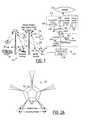
- FIG. 1is a system diagram of a communication system according to the present invention.
- FIG. 2Ais a top view of a base station antenna according to the present invention.
- FIG. 2Bis a side view of the base station antenna of FIG. 2A .
- FIG. 2Cis a side view of a panel of the base station of FIG. 2A illustrating elements thereon.
- FIG. 2Dis an alternative side view showing elements of a panel of a base station.
- FIG. 2Eis a third alternative embodiment of elements of a panel of an antenna according to the present invention.
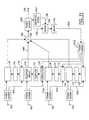
- FIG. 3is a high level block diagrammatic view of element modules coupled to a data bus.
- FIG. 4is a beam pattern for the panel illustrated in FIG. 2 .
- FIG. 5is a block diagrammatic view of a digital beam forming circuit according to the present invention.
- FIG. 6is a block diagrammatic view of a beam forming circuit using noise injection according to the present invention.
- FIG. 7is a block diagrammatic view of a base station processing circuit according to the present invention.
- FIG. 8is a block diagrammatic view of a gateway processing station according to the present invention.
- FIG. 9is a more detailed schematic view of a demultiplexing beam forming and nulling circuit according to the present invention.
- FIG. 10is an alternative for the remote processor; an adaptive digital beam forming and nulling processor according to the present invention.
- FIG. 11is an alternative nulling circuit with a limiter on the feedback path according to the present invention.
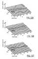
- FIG. 12Ais an output of a digital beam forming circuit not including limiter as shown in FIG. 10 .
- FIG. 12Bis an output of the circuit of FIG. 10 with limiters at all feed-through paths.
- FIG. 12Cis an output of circuit shown in FIG. 11 with limiter on the feed-back path, wherein the power density levels of both the weak and strong interference is successfully reduced below a threshold.
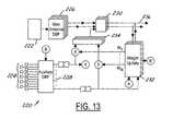
- FIG. 13is an alternative digital beam forming and nulling processor using auxiliary elements.
- a communications system 10has a plurality of beams 12 that are illustrated as a plurality of circles 14 on the earth's surface. Circles 14 represent the footprint of a radiated beam onto the earth's surface.
- a plurality of user terminals 16 M and 16 Fare used to illustrate mobile users and fixed users, respectively.
- Mobile users 16 Mmay comprise but are not limited to automotive applications, personal digital assistant applications and cellular phone applications.
- Fixed user terminals 16 Fmay, for example, comprise business-based or consumer-based communication systems.
- Each user terminal 16 F and 16 Mmay receive a signal with the predetermined signal strength from a communication beam or communication beams through multiple links from one or more base stations 18 .
- the present inventionis particularly advantageous for use with mobile terminals 16 M. Although only two wireless basestations are illustrated, they may each represent a plurality of basestations.
- Communication system 10further includes a gateway station 20 that is coupled to terrestrial networks 22 .
- Gateway station 20may be coupled to a base station processing center 24 .
- Gateway station 20provides a links between user terminals 16 F, 16 M and terrestrial networks 22 through base stations 18 .
- Gateway station 20may be coupled to terrestrial networks 22 such as the public service telephone network, the Internet, or an intranet. Although illustrated as two separate units, gateway station 20 and processing center 24 may be combined into the same physical location.
- the communication signals between base station 18 and user terminals 16 M and 16 Fmay be referred to as user links 26 .
- User links 26represent the transmit and receive beams from both categories of user terminals 16 F, 16 M and base station 18 .
- a feeder link 28is defined between base station 18 and gateway station 20 .
- Base stations 18are used as a communication nodes for gateway station 20 and user terminals 16 F and 16 M.
- base stations 18For communicating with user terminals 16 M and 16 F, base stations 18 have an adaptive antenna 30 formed of panels of reconfigurable elements as will be further described below.
- Each base station 30also has a directional antenna 32 for coupling to gateway station antenna 34 .
- the coupling of antennas 32 and 34allows base station 18 to be wireless and therefore advantageously be easily deployed.
- the pointing from both mobile terminals 16 M and base station 18may be performed electronically.
- Gateway station 20has a gateway control circuit 23 that controls the content and communication with the base station 18 .
- Base station 18has a controller 36 that links user terminals 16 M, 16 F through antenna 32 with gateway station 20 .
- the controller 36is used in the return link direction to multilplex received signals from all the array element into the feeder link signals 28 as determined in the gateway station 20 .
- controller 36is used to de-multiplex the feeder link signals into various streams of signals for array elements to transmit.
- Gateway control circuit 23may have various circuitry coupled thereto. For example, analog or digital TV 38 , an up converter 40 , and a cable modem terminal shelf (CMTS) 42 .
- CMTS 42may be used to couple to terrestrial networks such as Internet 22 .
- CMTS 42may be coupled to a hub 44 that has various resources coupled thereto.
- the hub 44may, for example, have a management server 46 , a world wide web, e-mail or news server 48 or a proxy server 50 .
- antenna 30has five panels 52 that are used to direct communication signals to a desired direction.
- each panel 52has a field of view and a scanning range slightly narrower than the field of view.
- Each panelis preferably a flat panel that allows cost effective multiple connectivity from base station 18 to the various users.
- Each panel 52is used to establish multiple dynamic links.
- the various base stations togetherare used to form the communication signal with the users.
- multiple base stations through multiple panels 52 of antennas 30are used in each communication.
- the bandwidth on demandis accomplished not by a variety of data rates via a single rf link but through different data rates resulting from various combinations of multiple dynamic rf links.
- some linksmay fade away while new links may become available.
- multiple linkswill always be connected to a user.
- five panelsare used, however, those skilled in the art will recognize various numbers of panels may be used.
- panels 52have an angle 54 relative to the horizontal.
- Angle 54allows the communication signals generated at panels 54 to be directed slightly downward toward the earth's surface.
- angle 54depends on the height of base station 18 above the earth's surface. That is, as the height of the tower increases, the angle 54 decreases. The angle is such to give a desired service area for each panel 52 .
- the combination of simultaneous multiple beam capability on both the mobile terminals and base stationswill make overall mobile systems even more cost effective.
- a user through their associated multiple beam user device or appliancewill connect to an IP network by establishing multiple dynamic links through various base stations to the communication nodes of the Internet.
- precious mobile spectrummay be reused many times when mobile subscribers use directional antennas.
- the same amount of spectrumcan be used again and again to increase the bandwidth density (i.e., total bandwidth a mobile system can project into a unit area). Therefore, the system will provide more throughput for users and larger capacity for the operators, and more efficient utilization for regulators.
- Providing a high gain on both user terminals and base stationsallows the cell size to be extended extensively without impacting the bandwidth density.
- the bandwidth on demandwill be implemented through multiple dynamic links and thus multiple links will always be available to a user.
- a user with an omni directional terminalmay connect to one nearest base station with an rf channel (specified by frequency, time and/or code). This channel will not be assigned to other users as in a conventional cellular system.
- Adaptive antennas on base stationsallow operators to use the same channel again within the same “cell” but via different base stations, provided the base stations have the capability to directionally discriminate against interferences at the same channel as that intended user but at different directions.
- the base stationsmay include circuitry to null or offset interferences between the communication signals.
- an acquisition phasee.g., from a cold start
- all received beamswill be “on” to cover the entire field of view of a fan beam.
- the various beamswill have different elevation angles and azimuth angles to cover the search volume.
- the tracking mechanismuses a type of step scan principle.
- the signal strengths from adjacent received beamswill be monitored and compared with one coming from the main beam.
- the beam with the strongest signalwill be identified as a “locked” or main beam.
- the tracking base stationmay switch (i.e., step) a received beam from one position to an adjacent one with the strongest signal, and assign the transmit beam accordingly.
- a panel 52may be comprised of a plurality of radiation elements or patches 56 .
- Radiation elements 56may, for example, be described as a “patch array.” As is illustrated, 90 elements are illustrated in FIG. 2C .
- Each element 56has a diameter of 0.3 wavelengths.
- Element modulesare placed at slightly less than 0.7 wavelengths apart in a nearly square lattice.
- Panel 52may also be referred to as an “aperture.”
- Panel 52has a radiating area in the order of about 25 square wavelengths.
- the expected peak gain of a beamis 24 dB at the boresight, and about 22 dB at 45 degrees away from the boresight.
- Beam widths for the boresight elliptical beamis about 10 degrees in azimuth and 15 degrees in elevation respectively. The beams are dynamic and therefore assigned to track individual subscribers accordingly.
- FIG. 2Da 45 element panel 52 is illustrated. Such a panel has about 3 dB less gain than that of the panel illustrated in FIG. 2C while maintaining about the same directional discrimination.
- long baselines, not full apertures, over a large bandwidthprovide good directional discrimination capability.
- the thin array at a single frequencywill exhibit high side lobes or semi-grading lobes. Over a large bandwidth, side lobes arise at various directions at different frequency components. As a result, the integrated interference contribution from side lobes over a large bandwidth tends to smear out or cancel while the contribution to the main lobe over the same bandwidth may be constructively added together.
- additional cancellation schemesmay be applied to reject interferences for all beams tracking to various subscribers if necessary.
- radiating elements 56form modules 58 which are plugged into panels 52 .
- Panels 52serve as back plates which are interconnected through a bus 60 .
- Bus 60may include a DC power line 62 , an inflow data line 63 , an outflow data line 64 , an address line 65 , and a control line 66 .
- Panels 52may be modularized and include sockets for easy connection and disconnection of modules 58 .
- Each panel or back plate 52may include a processor 68 to handle beam configuration. Processor 68 may be part of controller 36 described above in FIG. 1 .
- Digital beam forming circuit 72has a plurality of elements 74 .
- Various groupings of elements 74are used to generate the simultaneous multiple links of the present invention.
- Each element 74is coupled to a corresponding analog-to-digital converter.
- a band pass filter(not shown) may also be coupled between element 74 and analog-to-digital converter 76 .
- the digital outputs from all of the analog-to-digital converters 76are weighted and summed, then grouped together to form beams 1 through M as illustrated.
- the beamsare formed by numerical multiplications using the direction vector beam 1 as illustrated as reference numeral 78 and through direction vector beam M as illustrated by reference numerals 80 through forming circuit 82 .
- Direct samplingsare used to simplify the architecture. Low cost is achieved by the use of an analog-to-digital converter 76 that allows analog-to-digital conversion of the received signals at rf directly allowing other processing to be performed digitally. High speed and low speed analog-to-digital conversion will over sample the received signals.
- a user signalis assumed to be about 5 MHz but could go as high as 30 MHz.
- a sampling ratewas chosen to be about 20 MBps per second with approximately a 4-bit resolution.
- Aperture time of the analog-to-digital convertermust less than one-eighth of the period of the carrier frequency. Therefore, at a 2 GHz carrier frequency, the aperture time of about 50 picoseconds is adequate.
- FIG. 6an alternative to the circuit configuration of FIG. 5 is illustrated.
- the number of analog-to-digital convertersis reduced and the dynamic range required for the individual analog-to-digital converters is also reduced.
- element 74may be weighted in block 88 before a summer 90 .
- Summer 90is used to group a number of elements together.
- Each summing block 90has an analog-to-digital converter 92 associated therewith.
- Each summing block 90may also be connected to a noise injection circuit 94 .
- Structured noisemay be added to the summing block 90 .
- the structured noisemay consist of orthogonal codes. A similar technique is described in U.S. Pat. No. 5,077,562 which is incorporated by reference herein.
- Each analog-to-digital converter 92is coupled to demultiplexer 96 .
- Demultiplexer 96is coupled to digital beam forming and interference rejection network 98 .
- Demultiplexer 96demultiplexes the outputs from analog-to-digital converters 92 and provides them to digital beam forming and interference rejection network 98 .
- Digital beam forming and interference rejection networkprovides a received signal to be processed by the processing center.
- FIG. 7a similar embodiment to that shown in FIG. 6 above is illustrated.
- a portion of the circuitmay be located in base station while the remaining portion of the circuit may be located in a processing center.
- Elements 74are coupled to weighted block 88 which in turn are coupled to summers 98 .
- a weighted block 100is used after summer to couple summer 90 with a central summing block 102 . The signal from summing block 102 is thus broadcast or transmitted to the gateway station for further processing.
- a demultiplexer 96similar to that illustrated above is used.
- Demultiplexer 96demultiplexes the broadcast signal from summer 102 and provides it to an analog-to-digital converter 106 .
- Analog-to-digital converter 106may be coupled to noise injection circuit 108 .
- Noise injection circuit 108may be similar to that described above in that noise injection circuit 108 may use orthogonal codes.
- the output of analog-to-digital converteris provided to a demultiplexer portion 108 which in turn is coupled to digital beam forming and interference rejection network 98 similar to that in FIG. 6 .
- digital beam forming network and digital interference rejection networkprovides received signals from the various beams.
- FIG. 9a more detailed processing scheme for a CDMA system, such as 3rd generation mobile, from that shown in FIGS. 8 is illustrated.
- a diplexer 110is connected to a radiator (not shown) so that both transmit and receive signals are through the same radiator. Only the receive functions are illustrated. The corresponding transmit functions are identical but in a reversed direction.
- the received multiplexed signalsare coupled to an analog-to-digital converter 112 . To simplify the block diagram, we did not include the noise injection portion in here.
- a element code despreading circuit 114has a plurality of multiplication blocks 116 which performs the matched filter function via a multiplication 116 and a band pass filter 118 , to recover the signal received at a specific array element in digital representation. Therefore at the outputs of the de-spreading block 114 , the received signals of all the array elements at the remote base stations have been re-generated in digital forms. The regenerated signals are available for further processing.
- Element code despreading circuit 114is coupled to a user code despreading circuit 120 .
- Each user codeis used to group multiple users with the same user code together in user code despreading circuit 120 . Different users may only be separated via time delay and direction of arrival. Thus the block 120 must provide digital streams with multiple taps to beam forming network so that the user signals with the same user code can be separated via time and directional “filtering processes.”
- Each user code from user code despreading circuit 120is coupled to digital beam and null forming network. One digital beam and null forming network is provided for each user.
- Track files 124provide input to digital beam forming and null forming network 122 . Track files include information such as the user code, the location, timing and orientation of the users.
- Track filesallow the communication signals to be divided into several links for communication through a number of base stations.
- the user signals after digital beam formingare output and coupled to such things as the Internet.
- Feedbackis provided from output 126 through an extended Kalman filter.
- the extended Kalman filter 128is used to update each user position channel and potential for interference or collision with neighbors. The information from the extended Kalman filter 128 will be used to track the corresponding user.
- circuit 130that could be used with any of the circuits in FIGS. 7 through 9 is illustrated.
- the circuit 142 of FIG. 10may be implemented as a part of element 122 of FIG. 9 .
- Circuit 130has elements 132 which are coupled to a beam forming circuit 134 and an analog-to-digital converter 136 .
- a multiplication block 138 and amplifier 140may also be included in the circuit.
- a digital beam forming and nulling processor 142is coupled to each analog-to-digital converter. Each signal is multiplied by a weight at multiplication block 144 prior to being summed at a summer 146 .
- the output of summer 146is the output signal Y(t).
- the directional vector(the multiplier set) is pre-determined by pointing direction only, and usually will exhibit a linear phase progression on the array apertures for spot beams .
- the directional vectorwill be further modulated by signal environment, such that a beam is directed toward desired user while nulls are steered toward high interference directions. As a result the received signal to noise (including interference) ratio is “maximized.”
- Negative feedback block 147is provided from output signal Y (t) to a multiplication block 148 for each signal.
- the multiplication block 148multiplies the input signal from each analog-to-digital converter with the output signal Y (t) .
- a sum through summer block 150is provided to a weight update block 152 .
- Weight update block 152thus in response to the multiplication block 148 , updates the weights and provides those to multiplication blocks 144 .
- the outputis thus,
- Limiting circuit 160includes elements 162 similar to those described above. Each element has an associated main channel 164 , a feedthrough path 166 , and a feedback path 168 . Since the circuitry associated with the respective elements are essentially the same, the circuitry associated with only one sensor is referenced in detail.
- the function blockscan all implemented in digital format. For Instance, power dividers correspond to data bus, weight circuits to multipliers, correlators to processors combining multipliers and integration-&-dumps, outputs of hard limiters to sign bits, and so on.
- Correlators 170co-process signals in the feedthrough path 166 and feedback path 168 ; the result is transformed according to an algorithm by a computer 172 .
- the weighting circuit 174thus progressively modifies the signal in the main channel 164 to minimize interference with a desired signal.
- a limiter 176is placed along feedback path 168 . As explained below, this placement simplifies correlator design relative to the circuit without such limiters and improves performance relative to adaptive antennas with limiters in the feedthrough path.
- Each element 162is connected via the respective main channel 164 to respective input power divider 180 or other means for dividing an input signal between a pre-processed signal and a diagnostic signal.
- a diagnostic signalis conveyed along the respective feedthrough path 166 ; the pre-process signal is conveyed along a second portion 182 of the respective main channel 164 .
- the amplitude and phase of pre-process signalsmay be modified by weighting circuit 174 or other weighting means associated with each of the elements 162 .
- the resulting weighted signalsare directed along a third portion 184 of respective main channel 164 to be summed by means such as a power combiner 186 .
- Meanssuch as an output power divider 188 inserted along a unified portion 190 of main channel 14 between the power combiner 186 and antenna output 192 , divides the summed signal between an output signal and a feedback signal.
- the illustrated feedback path 168includes means for eliminating from the feedback signal the desired band of frequencies associated with the primary signal source to be received by circuit 160 .
- This meansmay include a hybrid 194 for subtracting the desired band from a portion of the summed signal. More particularly, hybrid 194 includes a primary input 196 and a secondary input 198 .
- the primary input 196receives a portion of the summed signal from output power divider 188 .
- the secondary input 198receives only the part of the summed input with the desired band.
- the desired bandmay be provided by means of a band pass filter 200 , the input of which is a portion of the summed signal directed thereto by output power divider 188 .
- the output of hybridis the summed signal less the desired band.
- limiter 176is located in feedback path 168 so that limiting occurs prior to division of the feedback signal. Thus, the need for plural limiters is obviated.
- limiter 176is a hard limiter.
- a hard limitertransforms a sinusoidal input to a square wave output.
- the limited feedback signalis divided by means such as power divider 202 to provide feedback signals to provide feedback inputs 204 of correlators 170 .
- the feedback signalis correlated with the diagnostic signal received at feedthrough input 206 of each correlator 170 .
- the preferred correlator 170is a multiplier coupled with a low pass filter.
- Each correlation resultantis transformed according to an algorithm by computer or processor 172 or alternative means.
- the transformis used to determine the weighting function of the weighting circuit 174 or other weighting means.
- a gradient descent algorithmsuch as least means square error, Howell-Applebaum power inversion, is used.
- the function of the ideal hard limiteris to produce a high constant level positive output whenever the input is positive and a low constant level negative output whenever the input is negative.
- the transition between the constant positive and negative output values (or the threshold values)is a sharp or discontinuous one. Therefore, with a sinusoidal input the output would ideally be a square wave.
- the limiterwill suppress weaker signals and enhance the strongest signal. Qualitatively, the limiter will only respond to the strongest signal.
- each elementshares the same field of view as every other element. Therefore, each element plays a nearly equal role in forming a single beam. All jamming signals in the field of view are sensed by every single element in the phased array. Consequently, the positioning of the limiter in either the feedthrough path or the feedback path is critical for multi-interference rejection in the phased array.
- the limiterIf the limiter is placed in the feedthrough path, its output will have merely the information of the strongest interference, and the antenna system will null against the strongest interference accordingly.
- the correlator outputswill not include any of the other interference signal information to allow the antenna system to form nulls in their directions.
- the antenna systemcan first null against the strongest interference signal until it becomes comparable to the second strongest. The antenna system will then null against both until the antenna system reaches an inherent threshold level, created by quantization error or feedback loop gain, limiter, etc.
- FIG. 12shows a comparison of the interference suppression performance and the convergence rate of three four-element phased array configurations: (a) no limiter, (b) limiters in the feedthrough path, and (c) limiter in the feedback path.
- the strongest interferenceis monotomically reduced until it is below the threshold value at iteration 37 , as show in FIG. 12A .
- the threshold valueis set 35 dB below the strongest interference.
- the weaker interferencewas not a driving force until iteration 34 . At this point, the weaker interference is slowly but continuously suppressed.
- the interference signalis below the threshold value.
- the desired signal power density at the outputis continually being enhanced until it reaches a steady state value of 10 dB above the threshold at iteration 134 .
- the system configurationworks but it needs high dynamic range correlators. In order to reduce high dynamic requirement on correlators, limiters are incorporated in the many modified options, as shown below.
- the power density level of the stronger interferenceis successively reduced below threshold but the power density level of the weak interference increases initially and remains at that steady state value as shown in FIG. 12B .
- the desired signalincreases slightly in value, but is never enhanced above the weak interference. This system does not respond adequately to the weaker interference signals.
- the power density levels of both the weak and strong interferenceare successfully reduced below the threshold as seen in FIG. 12C .
- the weaker interferenceis suppressed slightly faster.
- the weak interferenceis below threshold at iteration 87 . Throughout this process, the desired signal is continuously enhanced.
- the present inventionprovides for improved performance over the no-limiter and limiter in the feedthrough path designs of the prior art.
- the present inventionfurther improves on the feedthrough limiter version by requiring only one limiter, and improves upon the no-limiter version in relieving the design requirements on the correlators.
- FIG. 13another circuit 220 to provide nulling is illustrated.
- a plurality of main array elements 222 and auxiliary elements 224is illustrated.
- Main array elements 222are similar to the elements described in the previous circuit.
- Auxiliary elements 224have been added to provide canceling of side lobes from the main elements. This will provide the capability to allow users to be closer together without interference.
- Main array elements 222are coupled to a main digital beam forming circuit 226 .
- Auxiliary elements 224are coupled to an auxiliary digital beam forming circuit 228 .
- a summing block 230sums the signals from the main array elements through main digital beam forming circuit 226 with weighted portions of auxiliary elements to cancel interference. Feedback is provided through a weight update block 232 .
- Weight update block 232generates a weight for each of the user signals and provides them to a multiplication block where they are combined with the output of auxiliary digital beam forming circuit 228 .
- the output of digital beam forming circuitmay also be coupled to weight update block 232 to allow the weights to be formed as a function of the auxiliary digital beam forming input.
- the weighted auxiliary digital beam forming signalsare combined in a summer 234 where they are combined with each of the auxiliary digital beam forming circuits and provided summer 230 for providing interference cancellation.
- output 236 of circuit 220has the main user signals interference compensated for by the auxiliary elements 224 .
- main array elements 222are used to generate the communication beams of the present invention.
- the auxiliary elements 224are used to cancel interference from the main array elements as needed. That is, by using the positions of the users, weights may be determined for auxiliary elements 224 so that the auxiliary elements 224 will have an auxiliary element output to cancel interference from the communication beams because of the direction of strong interfering sources for each active beam may be determined from the user position. Preferably, this is performed in the gateway station to prevent complexity in the base station. As those skilled in the art will recognize, it is the side lobes of the main beam that are to be canceled. By providing the auxiliary elements, the side lobes of the main beams may be reduced or selectively canceled by the auxiliary element outputs. Each panel described above may include canceling of the side lobes using auxiliary elements.
- the gateway stationmay adaptively change the output of the auxiliary elements on a continual basis.
Landscapes
- Engineering & Computer Science (AREA)
- Computer Networks & Wireless Communication (AREA)
- Signal Processing (AREA)
- Mobile Radio Communication Systems (AREA)
- Radio Transmission System (AREA)
- Variable-Direction Aerials And Aerial Arrays (AREA)
Abstract
Description
Claims (5)
Priority Applications (6)
| Application Number | Priority Date | Filing Date | Title |
|---|---|---|---|
| US09/858,387US8396513B2 (en) | 2001-01-19 | 2001-05-15 | Communication system for mobile users using adaptive antenna |
| CA002433391ACA2433391C (en) | 2001-01-19 | 2002-01-11 | Communication system for mobile users using adaptive antenna |
| MXPA03006458AMXPA03006458A (en) | 2001-01-19 | 2002-01-11 | Communication system for mobile users using adaptive antenna. |
| PCT/US2002/000842WO2002058186A2 (en) | 2001-01-19 | 2002-01-11 | Communication system for mobile users using adaptive antenna |
| EP02709007AEP1374615A2 (en) | 2001-01-19 | 2002-01-11 | Communication system for mobile users using adaptive antenna |
| US13/771,601US8706167B2 (en) | 2001-01-19 | 2013-02-20 | Communication system for mobile users using adaptive antenna with auxiliary elements |
Applications Claiming Priority (4)
| Application Number | Priority Date | Filing Date | Title |
|---|---|---|---|
| US26270101P | 2001-01-19 | 2001-01-19 | |
| US26271701P | 2001-01-19 | 2001-01-19 | |
| US26668401P | 2001-02-05 | 2001-02-05 | |
| US09/858,387US8396513B2 (en) | 2001-01-19 | 2001-05-15 | Communication system for mobile users using adaptive antenna |
Related Child Applications (1)
| Application Number | Title | Priority Date | Filing Date |
|---|---|---|---|
| US13/771,601ContinuationUS8706167B2 (en) | 2001-01-19 | 2013-02-20 | Communication system for mobile users using adaptive antenna with auxiliary elements |
Publications (2)
| Publication Number | Publication Date |
|---|---|
| US20020128044A1 US20020128044A1 (en) | 2002-09-12 |
| US8396513B2true US8396513B2 (en) | 2013-03-12 |
Family
ID=27500747
Family Applications (2)
| Application Number | Title | Priority Date | Filing Date |
|---|---|---|---|
| US09/858,387Expired - Fee RelatedUS8396513B2 (en) | 2001-01-19 | 2001-05-15 | Communication system for mobile users using adaptive antenna |
| US13/771,601Expired - Fee RelatedUS8706167B2 (en) | 2001-01-19 | 2013-02-20 | Communication system for mobile users using adaptive antenna with auxiliary elements |
Family Applications After (1)
| Application Number | Title | Priority Date | Filing Date |
|---|---|---|---|
| US13/771,601Expired - Fee RelatedUS8706167B2 (en) | 2001-01-19 | 2013-02-20 | Communication system for mobile users using adaptive antenna with auxiliary elements |
Country Status (5)
| Country | Link |
|---|---|
| US (2) | US8396513B2 (en) |
| EP (1) | EP1374615A2 (en) |
| CA (1) | CA2433391C (en) |
| MX (1) | MXPA03006458A (en) |
| WO (1) | WO2002058186A2 (en) |
Cited By (2)
| Publication number | Priority date | Publication date | Assignee | Title |
|---|---|---|---|---|
| US20160329636A1 (en)* | 2015-05-08 | 2016-11-10 | Sony Mobile Communications Inc. | Beamforming control based on monitoring of multiple beams |
| US9553659B2 (en) | 2013-05-07 | 2017-01-24 | The Boeing Company | Systems and methods for directing communication signals to mobile platforms |
Families Citing this family (48)
| Publication number | Priority date | Publication date | Assignee | Title |
|---|---|---|---|---|
| US6337980B1 (en) | 1999-03-18 | 2002-01-08 | Hughes Electronics Corporation | Multiple satellite mobile communications method and apparatus for hand-held terminals |
| US6388615B1 (en) | 2000-06-06 | 2002-05-14 | Hughes Electronics Corporation | Micro cell architecture for mobile user tracking communication system |
| US6895217B1 (en) | 2000-08-21 | 2005-05-17 | The Directv Group, Inc. | Stratospheric-based communication system for mobile users having adaptive interference rejection |
| US6941138B1 (en) | 2000-09-05 | 2005-09-06 | The Directv Group, Inc. | Concurrent communications between a user terminal and multiple stratospheric transponder platforms |
| US7317916B1 (en) | 2000-09-14 | 2008-01-08 | The Directv Group, Inc. | Stratospheric-based communication system for mobile users using additional phased array elements for interference rejection |
| US7369847B1 (en) | 2000-09-14 | 2008-05-06 | The Directv Group, Inc. | Fixed cell communication system with reduced interference |
| US20020073437A1 (en)* | 2000-12-12 | 2002-06-13 | Hughes Electronics Corporation | Television distribution system using multiple links |
| US7400857B2 (en) | 2000-12-12 | 2008-07-15 | The Directv Group, Inc. | Communication system using multiple link terminals |
| US6891813B2 (en) | 2000-12-12 | 2005-05-10 | The Directv Group, Inc. | Dynamic cell CDMA code assignment system and method |
| US6952580B2 (en)* | 2000-12-12 | 2005-10-04 | The Directv Group, Inc. | Multiple link internet protocol mobile communications system and method therefor |
| US7181162B2 (en) | 2000-12-12 | 2007-02-20 | The Directv Group, Inc. | Communication system using multiple link terminals |
| US7103317B2 (en)* | 2000-12-12 | 2006-09-05 | The Directv Group, Inc. | Communication system using multiple link terminals for aircraft |
| US8396513B2 (en) | 2001-01-19 | 2013-03-12 | The Directv Group, Inc. | Communication system for mobile users using adaptive antenna |
| US7809403B2 (en) | 2001-01-19 | 2010-10-05 | The Directv Group, Inc. | Stratospheric platforms communication system using adaptive antennas |
| US7187949B2 (en) | 2001-01-19 | 2007-03-06 | The Directv Group, Inc. | Multiple basestation communication system having adaptive antennas |
| US7068616B2 (en)* | 2001-02-05 | 2006-06-27 | The Directv Group, Inc. | Multiple dynamic connectivity for satellite communications systems |
| US20030069043A1 (en)* | 2001-10-10 | 2003-04-10 | Pallav Chhaochharia | Methods and devices for wirelessly transmitting data in dependence on location |
| US20040242257A1 (en)* | 2001-10-22 | 2004-12-02 | Kimmo Valkealahti | Pilot channel power autotuning |
| US7453861B2 (en)* | 2002-08-02 | 2008-11-18 | At&T Corp | System and method for estimating interference in a packet-based wireless network |
| US20040252665A1 (en)* | 2003-06-11 | 2004-12-16 | Clark Andrew C. | Method for increasing wireless communication system capacity |
| US9231729B2 (en)* | 2012-02-28 | 2016-01-05 | Spatial Digital Systems, Inc. | Resource allocation in PON networks via wave-front multiplexing and de-multiplexing |
| US8767862B2 (en) | 2012-05-29 | 2014-07-01 | Magnolia Broadband Inc. | Beamformer phase optimization for a multi-layer MIMO system augmented by radio distribution network |
| US8797969B1 (en) | 2013-02-08 | 2014-08-05 | Magnolia Broadband Inc. | Implementing multi user multiple input multiple output (MU MIMO) base station using single-user (SU) MIMO co-located base stations |
| US9343808B2 (en) | 2013-02-08 | 2016-05-17 | Magnotod Llc | Multi-beam MIMO time division duplex base station using subset of radios |
| US20140226740A1 (en) | 2013-02-13 | 2014-08-14 | Magnolia Broadband Inc. | Multi-beam co-channel wi-fi access point |
| US9155110B2 (en) | 2013-03-27 | 2015-10-06 | Magnolia Broadband Inc. | System and method for co-located and co-channel Wi-Fi access points |
| US9100968B2 (en) | 2013-05-09 | 2015-08-04 | Magnolia Broadband Inc. | Method and system for digital cancellation scheme with multi-beam |
| US9425882B2 (en) | 2013-06-28 | 2016-08-23 | Magnolia Broadband Inc. | Wi-Fi radio distribution network stations and method of operating Wi-Fi RDN stations |
| US8995416B2 (en) | 2013-07-10 | 2015-03-31 | Magnolia Broadband Inc. | System and method for simultaneous co-channel access of neighboring access points |
| US9497781B2 (en) | 2013-08-13 | 2016-11-15 | Magnolia Broadband Inc. | System and method for co-located and co-channel Wi-Fi access points |
| US9088898B2 (en) | 2013-09-12 | 2015-07-21 | Magnolia Broadband Inc. | System and method for cooperative scheduling for co-located access points |
| US9060362B2 (en) | 2013-09-12 | 2015-06-16 | Magnolia Broadband Inc. | Method and system for accessing an occupied Wi-Fi channel by a client using a nulling scheme |
| US9172454B2 (en) | 2013-11-01 | 2015-10-27 | Magnolia Broadband Inc. | Method and system for calibrating a transceiver array |
| US8891598B1 (en) | 2013-11-19 | 2014-11-18 | Magnolia Broadband Inc. | Transmitter and receiver calibration for obtaining the channel reciprocity for time division duplex MIMO systems |
| US8942134B1 (en) | 2013-11-20 | 2015-01-27 | Magnolia Broadband Inc. | System and method for selective registration in a multi-beam system |
| US8929322B1 (en)* | 2013-11-20 | 2015-01-06 | Magnolia Broadband Inc. | System and method for side lobe suppression using controlled signal cancellation |
| US9014066B1 (en) | 2013-11-26 | 2015-04-21 | Magnolia Broadband Inc. | System and method for transmit and receive antenna patterns calibration for time division duplex (TDD) systems |
| US9294177B2 (en) | 2013-11-26 | 2016-03-22 | Magnolia Broadband Inc. | System and method for transmit and receive antenna patterns calibration for time division duplex (TDD) systems |
| US9042276B1 (en) | 2013-12-05 | 2015-05-26 | Magnolia Broadband Inc. | Multiple co-located multi-user-MIMO access points |
| US9172446B2 (en) | 2014-03-19 | 2015-10-27 | Magnolia Broadband Inc. | Method and system for supporting sparse explicit sounding by implicit data |
| US9100154B1 (en) | 2014-03-19 | 2015-08-04 | Magnolia Broadband Inc. | Method and system for explicit AP-to-AP sounding in an 802.11 network |
| US9271176B2 (en) | 2014-03-28 | 2016-02-23 | Magnolia Broadband Inc. | System and method for backhaul based sounding feedback |
| US9954590B2 (en) | 2014-05-23 | 2018-04-24 | Mediatek Inc. | Methods for efficient beam training and communications apparatus and network control device utilizing the same |
| US9876549B2 (en)* | 2014-05-23 | 2018-01-23 | Mediatek Inc. | Methods for efficient beam training and communications apparatus and network control device utilizing the same |
| US10171139B1 (en)* | 2016-02-02 | 2019-01-01 | Ethertronics, Inc. | Inter-dwelling signal management using reconfigurable antennas |
| CN110022566B (en)* | 2018-01-10 | 2022-05-27 | 深圳捷豹电波科技有限公司 | Wireless communication control method, radio device and apparatus |
| US11197174B1 (en) | 2020-07-15 | 2021-12-07 | Shenzhen Jaguar Wave Technology Ltd. | Method for controlling wireless communication, radio device, and storage device |
| CN112350073B (en)* | 2020-09-29 | 2021-11-26 | 北京理工大学 | Ultra-large-diameter reflecting antenna based on secondary mirror array |
Citations (232)
| Publication number | Priority date | Publication date | Assignee | Title |
|---|---|---|---|---|
| US3541553A (en) | 1968-03-27 | 1970-11-17 | Rca Corp | Satellite communications systems |
| US3720953A (en) | 1972-02-02 | 1973-03-13 | Hughes Aircraft Co | Dual polarized slot elements in septated waveguide cavity |
| US4085368A (en) | 1976-08-30 | 1978-04-18 | Bell Telephone Laboratories, Incorporated | Interference canceling method and apparatus |
| US4343005A (en) | 1980-12-29 | 1982-08-03 | Ford Aerospace & Communications Corporation | Microwave antenna system having enhanced band width and reduced cross-polarization |
| US4500883A (en)* | 1983-03-07 | 1985-02-19 | The United States Of America As Represented By The Secretary Of The Army | Adaptive multiple interference tracking and cancelling antenna |
| US4631499A (en)* | 1984-11-30 | 1986-12-23 | U.S. Philips Corporation | Phase-locked loop for a directly mixing synchronous AM-receiver |
| US4635063A (en) | 1983-05-06 | 1987-01-06 | Hughes Aircraft Company | Adaptive antenna |
| US4689625A (en) | 1984-11-06 | 1987-08-25 | Martin Marietta Corporation | Satellite communications system and method therefor |
| US4700361A (en) | 1983-10-07 | 1987-10-13 | Dolby Laboratories Licensing Corporation | Spectral emphasis and de-emphasis |
| US4727503A (en) | 1983-07-06 | 1988-02-23 | The Secretary Of State For Defence In Her Britannic Majesty's Government Of United Kingdom | Systolic array |
| US4799065A (en) | 1983-03-17 | 1989-01-17 | Hughes Aircraft Company | Reconfigurable beam antenna |
| US4812788A (en) | 1987-11-02 | 1989-03-14 | Hughes Aircraft Company | Waveguide matrix including in-plane crossover |
| US4819227A (en) | 1986-08-14 | 1989-04-04 | Hughes Aircraft Company | Satellite communications system employing frequency reuse |
| US4823341A (en) | 1986-08-14 | 1989-04-18 | Hughes Aircraft Company | Satellite communications system having frequency addressable high gain downlink beams |
| US4872015A (en)* | 1986-12-01 | 1989-10-03 | Hughes Aircraft Company | Satellite communications system for mobile users |
| US4893316A (en)* | 1985-04-04 | 1990-01-09 | Motorola, Inc. | Digital radio frequency receiver |
| US5017927A (en) | 1990-02-20 | 1991-05-21 | General Electric Company | Monopulse phased array antenna with plural transmit-receive module phase shifters |
| US5077562A (en) | 1990-12-24 | 1991-12-31 | Hughes Aircraft Company | Digital beam-forming technique using temporary noise injection |
| US5081464A (en) | 1990-07-12 | 1992-01-14 | Hughes Aircraft Company | Method and apparatus for producing multiple, frequency-addressable scanning beams |
| US5151706A (en) | 1991-01-31 | 1992-09-29 | Agence Spatiale Europeene | Apparatus for electronically controlling the radiation pattern of an antenna having one or more beams of variable width and/or direction |
| US5233626A (en) | 1992-05-11 | 1993-08-03 | Space Systems/Loral Inc. | Repeater diversity spread spectrum communication system |
| US5257030A (en) | 1987-09-22 | 1993-10-26 | Mitsubishi Denki Kabushiki Kaisha | Antenna system |
| US5278863A (en) | 1992-04-10 | 1994-01-11 | Cd Radio Incorporated | Radio frequency broadcasting systems and methods using two low-cost geosynchronous satellites |
| US5327455A (en) | 1991-09-11 | 1994-07-05 | Agence Spatiale Europeene | Method and device for multiplexing data signals |
| US5339330A (en) | 1990-03-19 | 1994-08-16 | David D. Otten | Integrated cellular communications system |
| US5345448A (en)* | 1992-04-27 | 1994-09-06 | Nokia Mobile Phones Ltd. | Procedure for the handover of a radio connection |
| US5361074A (en) | 1980-05-05 | 1994-11-01 | The United States Of America As Represented By The Secretary Of The Navy | Mainlobe canceller system |
| US5379320A (en) | 1993-03-11 | 1995-01-03 | Southern California Edison Company | Hitless ultra small aperture terminal satellite communication network |
| US5410731A (en) | 1991-03-22 | 1995-04-25 | Alcatel Espace | Satellite telecommunications facility capable of covering a plurality of coverage areas |
| EP0682416A2 (en) | 1994-05-09 | 1995-11-15 | Loral Qualcomm Satellite Services, Inc. | Satellite communication via plurality of communication paths with signal strength control |
| US5485485A (en) | 1992-04-10 | 1996-01-16 | Cd Radio Inc. | Radio frequency broadcasting systems and methods using two low-cost geosynchronous satellites and hemispherical coverage antennas |
| US5548801A (en) | 1993-02-10 | 1996-08-20 | Kokusai Denshin Denwa Kabushiki Kaisha | System for determining and registering location of mobile terminal for communication system with non-geosynchronous satellites |
| US5552798A (en)* | 1994-08-23 | 1996-09-03 | Globalstar L.P. | Antenna for multipath satellite communication links |
| US5568484A (en) | 1994-12-22 | 1996-10-22 | Matsushita Avionics Systems Corporation | Telecommunications system and method for use on commercial aircraft and other vehicles |
| US5572216A (en) | 1993-11-19 | 1996-11-05 | Stanford Telecommunications, Inc. | System for increasing the utility of satellite communication systems |
| US5584047A (en) | 1995-05-25 | 1996-12-10 | Tuck; Edward F. | Methods and apparatus for augmenting satellite broadcast system |
| US5589834A (en) | 1994-04-22 | 1996-12-31 | Stanford Telecommunications, Inc. | Cost effective geosynchronous mobile satellite communication system |
| US5592471A (en) | 1995-04-21 | 1997-01-07 | Cd Radio Inc. | Mobile radio receivers using time diversity to avoid service outages in multichannel broadcast transmission systems |
| US5594941A (en) | 1994-01-11 | 1997-01-14 | Ericsson Inc. | A cellular/satellite communications system with generation of a plurality of sets of intersecting antenna beams |
| US5608722A (en) | 1995-04-03 | 1997-03-04 | Qualcomm Incorporated | Multi-user communication system architecture with distributed receivers |
| US5612701A (en) | 1995-09-18 | 1997-03-18 | Motorola, Inc. | Adaptive beam pointing method and apparatus for a communication system |
| US5625864A (en) | 1994-05-25 | 1997-04-29 | Budow; Harry S. | Interactive digital video services system with store and forward capabilities |
| EP0776099A2 (en) | 1995-11-21 | 1997-05-28 | AT&T Corp. | Code division multiple access mobile radio system |
| US5659350A (en) | 1992-12-09 | 1997-08-19 | Discovery Communications, Inc. | Operations center for a television program packaging and delivery system |
| US5666128A (en)* | 1996-03-26 | 1997-09-09 | Lockheed Martin Corp. | Modular supertile array antenna |
| US5682195A (en) | 1992-12-09 | 1997-10-28 | Discovery Communications, Inc. | Digital cable headend for cable television delivery system |
| US5684799A (en) | 1995-03-28 | 1997-11-04 | Bell Atlantic Network Services, Inc. | Full service network having distributed architecture |
| US5689568A (en)* | 1995-06-29 | 1997-11-18 | Hughes Electronics | Medium access control for a mobile satellite system |
| US5715516A (en) | 1995-10-18 | 1998-02-03 | Cellular Telecom, Ltd. | Method and apparatus for wireless communication employing collector arrays |
| US5727065A (en) | 1994-11-14 | 1998-03-10 | Hughes Electronics | Deferred billing, broadcast, electronic document distribution system and method |
| US5729279A (en) | 1995-01-26 | 1998-03-17 | Spectravision, Inc. | Video distribution system |
| US5732351A (en) | 1995-08-31 | 1998-03-24 | Motorola, Inc. | Communication system and method for single channel hand-offs |
| US5732722A (en) | 1997-02-07 | 1998-03-31 | Mortvedt; David Michael | Cap for a toothpaste container having an incorporated spool of dental floss |
| US5734982A (en) | 1995-05-12 | 1998-03-31 | Nec Corporation | Radio communication system |
| US5740164A (en) | 1993-02-09 | 1998-04-14 | Teledesic Corporation | Traffic routing for satellite communication system |
| US5751971A (en) | 1995-07-12 | 1998-05-12 | Cabletron Systems, Inc. | Internet protocol (IP) work group routing |
| US5754139A (en) | 1996-10-30 | 1998-05-19 | Motorola, Inc. | Method and intelligent digital beam forming system responsive to traffic demand |
| US5764187A (en) | 1997-01-21 | 1998-06-09 | Ail Systems, Inc. | Direct digital synthesizer driven phased array antenna |
| US5790541A (en) | 1996-04-01 | 1998-08-04 | Motorola, Inc. | Apparatus, method, system and system method for distributed routing in a multipoint communication system |
| US5790546A (en) | 1994-01-28 | 1998-08-04 | Cabletron Systems, Inc. | Method of transmitting data packets in a packet switched communications network |
| US5790070A (en) | 1997-05-05 | 1998-08-04 | Motorola, Inc. | Network and method for controlling steerable beams |
| EP0860952A2 (en) | 1997-02-21 | 1998-08-26 | Hughes Electronics Corporation | Ground based beam forming utilizing synchronized code division multiplexing |
| US5805996A (en) | 1991-12-13 | 1998-09-08 | Nokia Telecommunications Oy | Base station with antenna coverage directed into neighboring cells based on traffic load |
| US5810284A (en) | 1995-03-15 | 1998-09-22 | Hibbs; Bart D. | Aircraft |
| US5839053A (en) | 1995-08-02 | 1998-11-17 | Agence Spatiale Europeene | System for transmitting radio signals from mobile terminals to provide space diversity for uplink signals via geostationary communication satellites |
| US5852721A (en) | 1994-06-08 | 1998-12-22 | Hughes Electronics Corporation | Method and apparatus for selectively retrieving information from a source computer using a terrestrial or satellite interface |
| US5856804A (en)* | 1996-10-30 | 1999-01-05 | Motorola, Inc. | Method and intelligent digital beam forming system with improved signal quality communications |
| US5862480A (en) | 1995-12-26 | 1999-01-19 | Motorola, Inc. | Method and apparatus for managing service accessibility between differing radio telecommunication networks |
| US5864579A (en) | 1996-07-25 | 1999-01-26 | Cd Radio Inc. | Digital radio satellite and terrestrial ubiquitous broadcasting system using spread spectrum modulation |
| US5867109A (en) | 1995-06-06 | 1999-02-02 | Globalstar L.P. | Satellite repeater diversity resource management system |
| US5878034A (en) | 1996-05-29 | 1999-03-02 | Lockheed Martin Corporation | Spacecraft TDMA communications system with synchronization by spread spectrum overlay channel |
| US5884142A (en)* | 1997-04-15 | 1999-03-16 | Globalstar L.P. | Low earth orbit distributed gateway communication system |
| US5890067A (en) | 1996-06-26 | 1999-03-30 | Bnr Inc. | Multi-beam antenna arrays for base stations in which the channel follows the mobile unit |
| US5894590A (en) | 1995-07-31 | 1999-04-13 | Motorola, Inc. | Independent satellite-based communications systems sharing common frequency spectrum and method of operation thereof |
| US5907816A (en) | 1995-01-27 | 1999-05-25 | Marconi Aerospace Systems Inc. Advanced Systems Division | High gain antenna systems for cellular use |
| US5909460A (en) | 1995-12-07 | 1999-06-01 | Ericsson, Inc. | Efficient apparatus for simultaneous modulation and digital beamforming for an antenna array |
| US5909470A (en) | 1996-10-11 | 1999-06-01 | Arraycomm, Inc. | Method and apparatus for decision directed demodulation using antenna arrays and spatial processing |
| US5918157A (en) | 1997-03-18 | 1999-06-29 | Globalstar L.P. | Satellite communications system having distributed user assignment and resource assignment with terrestrial gateways |
| US5917447A (en) | 1996-05-29 | 1999-06-29 | Motorola, Inc. | Method and system for digital beam forming |
| US5930680A (en) | 1994-06-17 | 1999-07-27 | Terrastar, Inc. | Method and system for transceiving signals using a constellation of satellites in close geosynchronous orbit |
| US5946625A (en) | 1996-10-10 | 1999-08-31 | Ericsson, Inc. | Method for improving co-channel interference in a cellular system |
| US5949766A (en) | 1996-12-30 | 1999-09-07 | Motorola, Inc. | Ground device for communicating with an elevated communication hub and method of operation thereof |
| US5956619A (en) | 1996-12-12 | 1999-09-21 | Globalstar L.P. | Satellite controlled power control for personal communication user terminals |
| US5963862A (en) | 1996-10-25 | 1999-10-05 | Pt Pasifik Satelit Nusantara | Integrated telecommunications system providing fixed and mobile satellite-based services |
| US5966371A (en) | 1997-10-17 | 1999-10-12 | At&T Corp. | Method and system for reducing interbeam interference and multipath fading in bent-pipe satellite communications systems |
| US5974317A (en) | 1996-11-08 | 1999-10-26 | Lucent Technologies, Inc. | Cell-clustering arrangements and corresponding antenna patterns for wireless communication networks employing high-altitude aeronautical antenna platforms |
| US5973647A (en) | 1997-09-17 | 1999-10-26 | Aerosat Corporation | Low-height, low-cost, high-gain antenna and system for mobile platforms |
| US5982337A (en) | 1998-02-20 | 1999-11-09 | Marconi Aerospace Systems Inc. | Cellular antennas for stratosphere coverage of multi-band annular earth pattern |
| US5990928A (en) | 1997-05-30 | 1999-11-23 | Rockwell International Corporation | Method and apparatus for receiving broadcast entertainment transmissions at a moving receiver station |
| US5991309A (en) | 1996-04-12 | 1999-11-23 | E.F. Johnson Company | Bandwidth management system for a remote repeater network |
| US5991329A (en) | 1995-06-30 | 1999-11-23 | Interdigital Technology Corporation | Automatic power control system for a code division multiple access (CDMA) communications system |
| US5990839A (en) | 1997-04-10 | 1999-11-23 | Telefonaktiebolaget L M Ericsson (Publ) | Adjustable antenna system for a portable radio unit in a satellite communication system |
| US5995062A (en)* | 1998-02-19 | 1999-11-30 | Harris Corporation | Phased array antenna |
| US6014372A (en) | 1997-12-08 | 2000-01-11 | Lockheed Martin Corp. | Antenna beam congruency system for spacecraft cellular communications system |
| US6016124A (en) | 1997-04-07 | 2000-01-18 | Nortel Networks Corporation | Digital beamforming in a satellite communication system |
| US6016421A (en) | 1997-11-17 | 2000-01-18 | Wireless Online, Inc. | Conflict resolution in a multi-beam multi-site paging system |
| US6018316A (en) | 1997-01-24 | 2000-01-25 | Ail Systems, Inc. | Multiple beam antenna system and method |
| US6020845A (en) | 1993-11-19 | 2000-02-01 | Stanford Telecommunications, Inc. | Satellite for increasing the utility of satellite communication systems |
| US6023463A (en) | 1997-02-06 | 2000-02-08 | Globalstar L.P. | Satellite telephone interference avoidance system |
| US6034634A (en) | 1997-10-24 | 2000-03-07 | Telefonaktiebolaget L M Ericsson (Publ) | Terminal antenna for communications systems |
| US6047186A (en) | 1997-10-06 | 2000-04-04 | Nortel Networks Corporation | Method and system for solving cellular communications frequency planning problem |
| US6049720A (en) | 1996-04-12 | 2000-04-11 | Transcrypt International / E.F. Johnson Company | Link delay calculation and compensation system |
| US6061562A (en) | 1997-10-30 | 2000-05-09 | Raytheon Company | Wireless communication using an airborne switching node |
| US6084541A (en)* | 1998-07-13 | 2000-07-04 | Comsat Corporation | Self diagnosis and self healing scheme for digital beam-forming |
| US6084892A (en) | 1997-03-11 | 2000-07-04 | Bell Atlantic Networks Services, Inc. | Public IP transport network |
| US6088341A (en) | 1998-09-28 | 2000-07-11 | Teledesic Llc | Method for reducing co-channel of cross-polarization interference in a satellite data communication system by offsetting channel frequencies |
| EP1026778A2 (en) | 1999-02-01 | 2000-08-09 | Lucent Technologies Inc. | System and method for controlling antenna downtilt/uptilt in a wireless communication network |
| US6105060A (en) | 1997-09-05 | 2000-08-15 | Worldspace, Inc. | System for providing global portable internet access using low earth orbit satellite and satellite direct radio broadcast system |
| US6104911A (en) | 1997-11-14 | 2000-08-15 | Motorola, Inc. | Communication system with satellite diversity and method of operation thereof |
| US6111542A (en) | 1998-04-06 | 2000-08-29 | Motorola, Inc. | Rotating electronically steerable antenna system and method of operation thereof |
| US6118824A (en) | 1991-12-16 | 2000-09-12 | Omnipoint Corporation | Spread-spectrum data publishing system |
| US6118998A (en)* | 1997-09-17 | 2000-09-12 | Lockheed Martin Corporation | Spacecraft cellular communication system with spot beam pairing for reduced updates |
| EP1037403A2 (en) | 1999-03-18 | 2000-09-20 | Hughes Electronics Corporation | Multiple satellite mobile communication method and apparatus for hand-held terminals receiving their signal radiated from a plurality of these satellites |
| US6128276A (en)* | 1997-02-24 | 2000-10-03 | Radix Wireless, Inc. | Stacked-carrier discrete multiple tone communication technology and combinations with code nulling, interference cancellation, retrodirective communication and adaptive antenna arrays |
| GB2349045A (en) | 1999-04-16 | 2000-10-18 | Fujitsu Ltd | Base station transmission beam pattern forming; interference reduction |
| US6147658A (en) | 1998-07-06 | 2000-11-14 | Murata Manufacturing Co., Ltd. | Array antenna device and radio equipment |
| US6151308A (en) | 1996-12-30 | 2000-11-21 | Motorola, Inc. | Elevated communication hub and method of operation therefor |
| US6151496A (en) | 1998-10-22 | 2000-11-21 | Raytheon Company | System and method of performing soft hand-off with one-dimensional AESA |
| US6157685A (en) | 1996-12-20 | 2000-12-05 | Fujitsu Limited | Interference canceller equipment and interference cancelling method for use in a multibeam-antenna communication system |
| US6157621A (en) | 1991-10-28 | 2000-12-05 | Teledesic Llc | Satellite communication system |
| US6157811A (en) | 1994-01-11 | 2000-12-05 | Ericsson Inc. | Cellular/satellite communications system with improved frequency re-use |
| US6160994A (en) | 1996-12-19 | 2000-12-12 | Globalstar L.P. | Interactive fixed and mobile satellite network |
| US6167237A (en) | 1997-02-28 | 2000-12-26 | U.S. Philips Corporation | Universal wireless communication system, a transmission protocol, a wireless communication station, and a radio base station |
| US6167286A (en)* | 1997-06-05 | 2000-12-26 | Nortel Networks Corporation | Multi-beam antenna system for cellular radio base stations |
| US6167263A (en) | 1997-05-16 | 2000-12-26 | Spherecore, Inc. | Aerial communications network including a plurality of aerial platforms |
| US6173178B1 (en) | 1997-12-16 | 2001-01-09 | Trw Inc. | Satellite beam pattern for non-uniform population distribution |
| US6173190B1 (en) | 1996-12-19 | 2001-01-09 | Sony Corporation | Signal receiving apparatus and method |
| US6178328B1 (en) | 1998-06-11 | 2001-01-23 | Nortel Networks Corporation | Method and system for solving cellular communications frequency planning problem |
| US6188896B1 (en) | 1999-02-22 | 2001-02-13 | Trw Inc. | Cellular satellite communication system and method for controlling antenna gain pattern therein |
| US6188912B1 (en) | 1998-06-05 | 2001-02-13 | World Access, Inc. | System for a base station for providing voice, data, and multimedia services in a wireless local loop system |
| US6195037B1 (en) | 1999-06-01 | 2001-02-27 | Motorola, Inc. | Method and apparatus for increased system capacity using antenna beamforming |
| US6201797B1 (en) | 1997-12-12 | 2001-03-13 | At&T Wireless Services Inc. | High bandwidth delivery and internet access for airborne passengers |
| US6204822B1 (en) | 1998-05-20 | 2001-03-20 | L-3 Communications/Essco, Inc. | Multibeam satellite communication antenna |
| US6208858B1 (en) | 1998-07-21 | 2001-03-27 | Qualcomm Incorporated | System and method for reducing call dropping rates in a multi-beam communication system |
| US6208307B1 (en) | 2000-04-07 | 2001-03-27 | Live Tv, Inc. | Aircraft in-flight entertainment system having wideband antenna steering and associated methods |
| US6215776B1 (en) | 1997-10-08 | 2001-04-10 | Lockheed Martin Missiles & Space Company | Satellite communication system |
| US6240072B1 (en) | 1997-04-07 | 2001-05-29 | Nortel Networks Limited | Piecewise coherent beamforming for satellite communications |
| US6249514B1 (en) | 1995-12-08 | 2001-06-19 | Worldspace International Network, Inc. | Satellite direct radio broadcast system |
| US20010004604A1 (en) | 1999-12-15 | 2001-06-21 | Kabushiki Kaisha Toshiba | Radio communication scheme |
| US6259415B1 (en) | 1996-06-03 | 2001-07-10 | Bae Systems Advanced Systems | Minimum protrusion mechanically beam steered aircraft array antenna systems |
| US6266528B1 (en) | 1998-12-23 | 2001-07-24 | Arraycomm, Inc. | Performance monitor for antenna arrays |
| US6269244B1 (en) | 1999-09-22 | 2001-07-31 | Ericsson Inc. | Enhanced cellular network architecture |
| US6272317B1 (en) | 1997-06-02 | 2001-08-07 | Hughes Electronics Corporation | Method and system for providing satellite coverage using fixed spot beams and scanned spot beams |
| EP1122813A2 (en) | 2000-02-04 | 2001-08-08 | Hughes Electronics Corporation | An improved phased array terminal for equatorial satellite constellations |
| US6278876B1 (en)* | 1997-07-14 | 2001-08-21 | Hughes Electronics Corporation | System and method for implementing terminal to terminal connections via a geosynchronous earth orbit satellite |
| US6289004B1 (en) | 1998-03-12 | 2001-09-11 | Interdigital Technology Corporation | Adaptive cancellation of fixed interferers |
| EP1139583A2 (en) | 2000-03-31 | 2001-10-04 | Hughes Electronics Corporation | Geo stationary communications system with minimal delay |
| US6301231B1 (en) | 1998-06-02 | 2001-10-09 | Amer A. Hassan | Satellite communication system with variable rate satellite link diversity |
| US6308045B1 (en) | 1995-11-14 | 2001-10-23 | Harris Corporation | Wireless ground link-based aircraft data communication system with roaming feature |
| US6308085B1 (en) | 1998-03-13 | 2001-10-23 | Kabushiki Kaisha Toshiba | Distributed antenna system and method of controlling the same |
| EP1148662A2 (en) | 2000-04-17 | 2001-10-24 | Hughes Electronics Corporation | Coherent synchronization of code division multiple access signals |
| US6314269B1 (en) | 1994-07-22 | 2001-11-06 | International Mobile Satelitte Organization | Multi-beam TDMA satellite mobile communications system |
| EP1152552A2 (en) | 2000-05-05 | 2001-11-07 | Hughes Electronics Corporation | System and method for two-way communications using a high altitude communication device |
| US20010038342A1 (en) | 2000-05-05 | 2001-11-08 | Foote Charles A. | Method and system for airborne meter communication |
| US6317420B1 (en) | 1999-06-25 | 2001-11-13 | Qualcomm Inc. | Feeder link spatial multiplexing in a satellite communication system |
| US6324398B1 (en) | 1996-02-26 | 2001-11-27 | Lucent Technologies Inc. | Wireless telecommunications system having airborne base station |
| EP1158698A2 (en) | 2000-05-22 | 2001-11-28 | Hughes Electronics Corporation | A multi-platform wireless communication system for a variety of different user types |
| EP1161001A2 (en) | 2000-06-02 | 2001-12-05 | Nec Corporation | Multi-beam receiving apparatus |
| WO2001093458A2 (en) | 2000-05-30 | 2001-12-06 | Hughes Electronics Corporation | Multi-node wireless communication system with multiple transponding platforms |
| WO2001095522A1 (en) | 2000-06-06 | 2001-12-13 | Hughes Electronics Corporation | Resource allocation method in a satellite diversity system |
| US6339707B1 (en) | 1997-06-02 | 2002-01-15 | Hughes Electronics Corporation | Method and system for providing wideband communications to mobile users in a satellite-based network |
| US6339708B1 (en) | 1997-05-22 | 2002-01-15 | At&T Corp. | Method and apparatus for communications resource allocation for a wireless communications system |
| US6339611B1 (en) | 1998-11-09 | 2002-01-15 | Qualcomm Inc. | Method and apparatus for cross polarized isolation in a communication system |
| US20020006795A1 (en) | 1997-10-17 | 2002-01-17 | Norin John L. | Non-uniform multi-beam satellite communications method |
| US6343205B1 (en) | 1995-11-30 | 2002-01-29 | Motient Services Inc. | Network operations center for mobile earth terminal satellite communications system |
| US6353600B1 (en) | 2000-04-29 | 2002-03-05 | Lgc Wireless, Inc. | Dynamic sectorization in a CDMA cellular system employing centralized base-station architecture |
| US6353643B1 (en)* | 1997-08-30 | 2002-03-05 | Samsung Electronics Co., Ltd. | Smart antenna receiver using pilot signal in CDMA mobile communication system and signal receiving method therefor |
| WO2001094969A3 (en) | 2000-06-06 | 2002-03-28 | Hughes Electronics Corp | A user positioning technique for multi-platform communication system |
| WO2001091310A3 (en) | 2000-05-22 | 2002-03-28 | Hughes Electronics Corp | Multi-node point-to-point satellite communication system employing multiple geo satellites |
| US6366256B1 (en) | 2000-09-20 | 2002-04-02 | Hughes Electronics Corporation | Multi-beam reflector antenna system with a simple beamforming network |
| US6366761B1 (en) | 1998-10-06 | 2002-04-02 | Teledesic Llc | Priority-based bandwidth allocation and bandwidth-on-demand in a low-earth-orbit satellite data communication network |
| US20020041575A1 (en) | 2000-08-02 | 2002-04-11 | Mobile Satellite Ventures Llc | Coordinated satellite-terrestrial frequency reuse |
| US6377802B1 (en) | 1992-03-06 | 2002-04-23 | Aircell, Inc. | Doppler insensitive non-terrestrial digital cellular communications network |
| US20020049055A1 (en)* | 1999-09-13 | 2002-04-25 | Cynthia Matthews | System and technique for plane switchover in an aircraft based wireless communication system |
| US6380893B1 (en) | 2000-09-05 | 2002-04-30 | Hughes Electronics Corporation | Ground-based, wavefront-projection beamformer for a stratospheric communications platform |
| US6385434B1 (en) | 1998-09-16 | 2002-05-07 | Motorola, Inc. | Wireless access unit utilizing adaptive spectrum exploitation |
| US6385647B1 (en) | 1997-08-18 | 2002-05-07 | Mci Communications Corporations | System for selectively routing data via either a network that supports Internet protocol or via satellite transmission network based on size of the data |
| US20020053987A1 (en) | 1997-02-21 | 2002-05-09 | Hughes Electronics Corporation | Method and system for determining a position of an object using two-way ranging in a polystatic satellite configuration |
| US20020055371A1 (en) | 2000-11-09 | 2002-05-09 | Shlomi Arnon | Cellular base station with remote antenna |
| US6388615B1 (en) | 2000-06-06 | 2002-05-14 | Hughes Electronics Corporation | Micro cell architecture for mobile user tracking communication system |
| US6388634B1 (en) | 2000-10-31 | 2002-05-14 | Hughes Electronics Corporation | Multi-beam antenna communication system and method |
| US6392611B1 (en) | 2000-08-17 | 2002-05-21 | Space Systems/Loral, Inc. | Array fed multiple beam array reflector antenna systems and method |
| US6393303B1 (en)* | 1997-02-13 | 2002-05-21 | Nokia Telecommunications Oy | Method and apparatus for directional radio communication |
| US6400925B1 (en) | 1999-02-25 | 2002-06-04 | Trw Inc. | Packet switch control with layered software |
| US20020073437A1 (en) | 2000-12-12 | 2002-06-13 | Hughes Electronics Corporation | Television distribution system using multiple links |
| US20020072374A1 (en) | 2000-12-12 | 2002-06-13 | Hughes Electronics Corporation | Communication system using multiple link terminals |
| US20020072332A1 (en) | 2000-12-12 | 2002-06-13 | Hughes Electronics Corporation | Communication system using multiple link terminals for aircraft |
| US20020072360A1 (en) | 2000-12-12 | 2002-06-13 | Chang Donald C.D. | Multiple link internet protocol mobile communications system and method therefor |
| US20020072361A1 (en) | 1999-06-29 | 2002-06-13 | Gerald M. Knoblach | Airborne constellation of communications platforms and method |
| US6408180B1 (en) | 1992-03-06 | 2002-06-18 | Aircell, Inc. | Ubiquitous mobile subscriber station |
| US20020081969A1 (en) | 2000-12-12 | 2002-06-27 | Hughes Electronics Corporation | Communication system using multiple link terminals |
| US20020080732A1 (en) | 2000-12-12 | 2002-06-27 | Hughes Electronics Corporation | Dynamic cell CDMA code assignment system and method |
| US6414646B2 (en) | 2000-03-21 | 2002-07-02 | Space Systems/Loral, Inc. | Variable beamwidth and zoom contour beam antenna systems |
| EP0883266A3 (en) | 1997-05-12 | 2002-07-03 | Kabushiki Kaisha Toshiba | Router device, datagram transfer method and communication system realizing handoff control for mobile terminals |
| US6424646B1 (en) | 1997-12-31 | 2002-07-23 | At&T Corp. | Integrated services director (ISD) overall architecture |
| US6429823B1 (en) | 2000-08-11 | 2002-08-06 | Hughes Electronics Corporation | Horn reflect array |
| US20020106041A1 (en) | 2001-02-05 | 2002-08-08 | Chang Donald C. D. | Sampling technique for digital beam former |
| US20020118654A1 (en) | 2001-02-05 | 2002-08-29 | Chang Donald C.D. | Multiple dynamic connectivity for satellite communications systems |
| US6445777B1 (en) | 1996-09-23 | 2002-09-03 | Netune Communications, Inc. | Mobile tele-computer network |
| US20020128044A1 (en) | 2001-01-19 | 2002-09-12 | Chang Donald C.D. | Communication system for mobile users using adaptive antenna |
| US6452962B1 (en) | 1999-06-11 | 2002-09-17 | Trw Inc. | Mitigation of co-channel interference in synchronization bursts in a multi-beam communication system |
| US20020132643A1 (en) | 2001-01-19 | 2002-09-19 | Chang Donald C.D. | Multiple basestation communication system having adaptive antennas |
| US6463294B1 (en) | 1997-04-09 | 2002-10-08 | Nokia Networks Oy | Reducing interference in a mobile communications system |
| US20020168991A1 (en) | 2001-05-08 | 2002-11-14 | Kochanski Gregory P. | Methods and apparatus for mitigating the effects of solar noise and the like on a wireless communication system |
| US6484213B1 (en) | 1998-09-09 | 2002-11-19 | Compaq Information Technologies Group, Inc. | Adapting networking device for enhancing performance of a hybrid networking system |
| US6507739B1 (en)* | 2000-06-26 | 2003-01-14 | Motorola, Inc. | Apparatus and methods for controlling a cellular communications network having airborne transceivers |
| US6510172B1 (en)* | 1997-03-04 | 2003-01-21 | Qualcomm, Inc. | Multi-user communication system architecture with distributed transmitters |
| US6513758B1 (en) | 2000-08-21 | 2003-02-04 | Hughes Electronics Corporation | High altitude platform control system |
| US6519477B1 (en) | 1997-03-25 | 2003-02-11 | Siemens Aktiengesellschaft | Method for channel estimation from received signals transmitted via a radio channel |
| US6526288B1 (en) | 1998-04-28 | 2003-02-25 | Koninklijke Philips Electronics, N.V. | System for connecting a data communication device over wireless terminals to a communication network |
| US6529706B1 (en) | 1999-09-13 | 2003-03-04 | Rockwell Collins, Inc. | Aircraft satellite communications system for distributing internet service from direct broadcast satellites |
| US6556845B1 (en) | 1998-09-18 | 2003-04-29 | Matsushita Electric Industrial Co., Ltd. | Base station device and transmission method |
| US6556809B1 (en)* | 1999-11-22 | 2003-04-29 | Motorola, Inc. | Method and apparatus for controlling communication beams within a cellular communication system |
| US6559797B1 (en) | 2001-02-05 | 2003-05-06 | Hughes Electronics Corporation | Overlapping subarray patch antenna system |
| US6560292B1 (en) | 2000-04-07 | 2003-05-06 | Qualcomm Incorporated | Method for coding in a telecommunications system |
| US6598014B1 (en) | 1999-10-21 | 2003-07-22 | Massachusetts Institute Of Technology | Closed-loop multistage beamformer |
| US6615024B1 (en) | 1998-05-01 | 2003-09-02 | Arraycomm, Inc. | Method and apparatus for determining signatures for calibrating a communication station having an antenna array |
| US6639551B2 (en) | 1999-08-11 | 2003-10-28 | China Academy Of Telecommunications Technology | Method of interference cancellation based on smart antenna |
| US6667715B1 (en) | 1999-08-18 | 2003-12-23 | Hughes Electronics Corporation | Signal processing circuit for communicating with a modular mobile satellite terminal and method therefor |
| US6704543B1 (en) | 1999-09-27 | 2004-03-09 | Ems Technologies, Inc. | Multi-beam satellite communications system |
| US6714800B2 (en) | 2001-05-02 | 2004-03-30 | Trex Enterprises Corporation | Cellular telephone system with free space millimeter wave trunk line |
| US6756937B1 (en) | 2000-06-06 | 2004-06-29 | The Directv Group, Inc. | Stratospheric platforms based mobile communications architecture |
| US6785558B1 (en) | 2002-12-06 | 2004-08-31 | Lgc Wireless, Inc. | System and method for distributing wireless communication signals over metropolitan telecommunication networks |
| US6819943B2 (en) | 2000-08-31 | 2004-11-16 | Millimetrix Broadband Networks Ltd. | Spatial spectral efficiency for wireless rings and network of links in millimeter wave (MMW) communication systems |
| US6895217B1 (en) | 2000-08-21 | 2005-05-17 | The Directv Group, Inc. | Stratospheric-based communication system for mobile users having adaptive interference rejection |
| US7088288B1 (en) | 2003-01-10 | 2006-08-08 | Xilinx, Inc. | Method and circuit for controlling an antenna system |
| US7200360B1 (en) | 2000-06-15 | 2007-04-03 | The Directv Group, Inc. | Communication system as a secondary platform with frequency reuse |
| US7317916B1 (en) | 2000-09-14 | 2008-01-08 | The Directv Group, Inc. | Stratospheric-based communication system for mobile users using additional phased array elements for interference rejection |
| US7369836B2 (en) | 2004-01-28 | 2008-05-06 | Pioneer Corporation | Adjacent interference removal device |
| EP0961416B1 (en) | 1997-06-03 | 2008-09-03 | Ntt Mobile Communications Network Inc. | Adaptive array transceiver |
| US7627284B2 (en) | 1999-01-07 | 2009-12-01 | The Directv Group, Inc. | Method and apparatus for providing wideband services using medium and low earth orbit satellites |
| US7664534B1 (en) | 2004-06-03 | 2010-02-16 | Sprint Spectrum L.P. | Communications system and method using remote antennas |
Family Cites Families (4)
| Publication number | Priority date | Publication date | Assignee | Title |
|---|---|---|---|---|
| US6467494B1 (en)* | 1999-08-18 | 2002-10-22 | Roediger Vakuum- Und Haustechnik Gmbh | Arrangement in a vacuum sewer system for preventing water entering a pneumatic controller through a breather line |
| US6941138B1 (en)* | 2000-09-05 | 2005-09-06 | The Directv Group, Inc. | Concurrent communications between a user terminal and multiple stratospheric transponder platforms |
| US7809403B2 (en)* | 2001-01-19 | 2010-10-05 | The Directv Group, Inc. | Stratospheric platforms communication system using adaptive antennas |
| JP2005105381A (en)* | 2003-10-01 | 2005-04-21 | Hitachi Ltd | Electron beam application equipment |
- 2001
- 2001-05-15USUS09/858,387patent/US8396513B2/ennot_activeExpired - Fee Related
- 2002
- 2002-01-11WOPCT/US2002/000842patent/WO2002058186A2/enactiveApplication Filing
- 2002-01-11MXMXPA03006458Apatent/MXPA03006458A/enactiveIP Right Grant
- 2002-01-11CACA002433391Apatent/CA2433391C/ennot_activeExpired - Lifetime
- 2002-01-11EPEP02709007Apatent/EP1374615A2/ennot_activeWithdrawn
- 2013
- 2013-02-20USUS13/771,601patent/US8706167B2/ennot_activeExpired - Fee Related
Patent Citations (259)
| Publication number | Priority date | Publication date | Assignee | Title |
|---|---|---|---|---|
| US3541553A (en) | 1968-03-27 | 1970-11-17 | Rca Corp | Satellite communications systems |
| US3720953A (en) | 1972-02-02 | 1973-03-13 | Hughes Aircraft Co | Dual polarized slot elements in septated waveguide cavity |
| US4085368A (en) | 1976-08-30 | 1978-04-18 | Bell Telephone Laboratories, Incorporated | Interference canceling method and apparatus |
| US5361074A (en) | 1980-05-05 | 1994-11-01 | The United States Of America As Represented By The Secretary Of The Navy | Mainlobe canceller system |
| US4343005A (en) | 1980-12-29 | 1982-08-03 | Ford Aerospace & Communications Corporation | Microwave antenna system having enhanced band width and reduced cross-polarization |
| US4500883A (en)* | 1983-03-07 | 1985-02-19 | The United States Of America As Represented By The Secretary Of The Army | Adaptive multiple interference tracking and cancelling antenna |
| US4799065A (en) | 1983-03-17 | 1989-01-17 | Hughes Aircraft Company | Reconfigurable beam antenna |
| US4635063A (en) | 1983-05-06 | 1987-01-06 | Hughes Aircraft Company | Adaptive antenna |
| US4727503A (en) | 1983-07-06 | 1988-02-23 | The Secretary Of State For Defence In Her Britannic Majesty's Government Of United Kingdom | Systolic array |
| US4700361A (en) | 1983-10-07 | 1987-10-13 | Dolby Laboratories Licensing Corporation | Spectral emphasis and de-emphasis |
| US4689625A (en) | 1984-11-06 | 1987-08-25 | Martin Marietta Corporation | Satellite communications system and method therefor |
| US4631499A (en)* | 1984-11-30 | 1986-12-23 | U.S. Philips Corporation | Phase-locked loop for a directly mixing synchronous AM-receiver |
| US4893316A (en)* | 1985-04-04 | 1990-01-09 | Motorola, Inc. | Digital radio frequency receiver |
| US4819227A (en) | 1986-08-14 | 1989-04-04 | Hughes Aircraft Company | Satellite communications system employing frequency reuse |
| US4823341A (en) | 1986-08-14 | 1989-04-18 | Hughes Aircraft Company | Satellite communications system having frequency addressable high gain downlink beams |
| US4872015A (en)* | 1986-12-01 | 1989-10-03 | Hughes Aircraft Company | Satellite communications system for mobile users |
| US5257030A (en) | 1987-09-22 | 1993-10-26 | Mitsubishi Denki Kabushiki Kaisha | Antenna system |
| US4812788A (en) | 1987-11-02 | 1989-03-14 | Hughes Aircraft Company | Waveguide matrix including in-plane crossover |
| US5017927A (en) | 1990-02-20 | 1991-05-21 | General Electric Company | Monopulse phased array antenna with plural transmit-receive module phase shifters |
| US5339330A (en) | 1990-03-19 | 1994-08-16 | David D. Otten | Integrated cellular communications system |
| US5081464A (en) | 1990-07-12 | 1992-01-14 | Hughes Aircraft Company | Method and apparatus for producing multiple, frequency-addressable scanning beams |
| US5077562A (en) | 1990-12-24 | 1991-12-31 | Hughes Aircraft Company | Digital beam-forming technique using temporary noise injection |
| US5151706A (en) | 1991-01-31 | 1992-09-29 | Agence Spatiale Europeene | Apparatus for electronically controlling the radiation pattern of an antenna having one or more beams of variable width and/or direction |
| US5410731A (en) | 1991-03-22 | 1995-04-25 | Alcatel Espace | Satellite telecommunications facility capable of covering a plurality of coverage areas |
| US5327455A (en) | 1991-09-11 | 1994-07-05 | Agence Spatiale Europeene | Method and device for multiplexing data signals |
| US6157621A (en) | 1991-10-28 | 2000-12-05 | Teledesic Llc | Satellite communication system |
| US5805996A (en) | 1991-12-13 | 1998-09-08 | Nokia Telecommunications Oy | Base station with antenna coverage directed into neighboring cells based on traffic load |
| US6118824A (en) | 1991-12-16 | 2000-09-12 | Omnipoint Corporation | Spread-spectrum data publishing system |
| US6377802B1 (en) | 1992-03-06 | 2002-04-23 | Aircell, Inc. | Doppler insensitive non-terrestrial digital cellular communications network |
| US6408180B1 (en) | 1992-03-06 | 2002-06-18 | Aircell, Inc. | Ubiquitous mobile subscriber station |
| US5485485A (en) | 1992-04-10 | 1996-01-16 | Cd Radio Inc. | Radio frequency broadcasting systems and methods using two low-cost geosynchronous satellites and hemispherical coverage antennas |
| US5278863A (en) | 1992-04-10 | 1994-01-11 | Cd Radio Incorporated | Radio frequency broadcasting systems and methods using two low-cost geosynchronous satellites |
| US5319673A (en) | 1992-04-10 | 1994-06-07 | Cd Radio Inc. | Radio frequency broadcasting systems and methods using two low-cost geosynchronous satellites |
| US5345448A (en)* | 1992-04-27 | 1994-09-06 | Nokia Mobile Phones Ltd. | Procedure for the handover of a radio connection |
| US5233626A (en) | 1992-05-11 | 1993-08-03 | Space Systems/Loral Inc. | Repeater diversity spread spectrum communication system |
| US5659350A (en) | 1992-12-09 | 1997-08-19 | Discovery Communications, Inc. | Operations center for a television program packaging and delivery system |
| US5682195A (en) | 1992-12-09 | 1997-10-28 | Discovery Communications, Inc. | Digital cable headend for cable television delivery system |
| US5740164A (en) | 1993-02-09 | 1998-04-14 | Teledesic Corporation | Traffic routing for satellite communication system |
| US5548801A (en) | 1993-02-10 | 1996-08-20 | Kokusai Denshin Denwa Kabushiki Kaisha | System for determining and registering location of mobile terminal for communication system with non-geosynchronous satellites |
| US5379320A (en) | 1993-03-11 | 1995-01-03 | Southern California Edison Company | Hitless ultra small aperture terminal satellite communication network |
| US6020845A (en) | 1993-11-19 | 2000-02-01 | Stanford Telecommunications, Inc. | Satellite for increasing the utility of satellite communication systems |
| US5572216A (en) | 1993-11-19 | 1996-11-05 | Stanford Telecommunications, Inc. | System for increasing the utility of satellite communication systems |
| US5594941A (en) | 1994-01-11 | 1997-01-14 | Ericsson Inc. | A cellular/satellite communications system with generation of a plurality of sets of intersecting antenna beams |
| US6157811A (en) | 1994-01-11 | 2000-12-05 | Ericsson Inc. | Cellular/satellite communications system with improved frequency re-use |
| US5790546A (en) | 1994-01-28 | 1998-08-04 | Cabletron Systems, Inc. | Method of transmitting data packets in a packet switched communications network |
| US5589834A (en) | 1994-04-22 | 1996-12-31 | Stanford Telecommunications, Inc. | Cost effective geosynchronous mobile satellite communication system |
| EP0682416A2 (en) | 1994-05-09 | 1995-11-15 | Loral Qualcomm Satellite Services, Inc. | Satellite communication via plurality of communication paths with signal strength control |
| US5625864A (en) | 1994-05-25 | 1997-04-29 | Budow; Harry S. | Interactive digital video services system with store and forward capabilities |
| US5995726A (en) | 1994-06-08 | 1999-11-30 | Hughes Electronics Corporation | Method and apparatus for requesting and retrieving information from a source computer using terrestrial and satellite interfaces |
| US6161141A (en) | 1994-06-08 | 2000-12-12 | Hughes Electronics Corporation | Network system with TCP/IP protocol spoofing |
| US5995725A (en) | 1994-06-08 | 1999-11-30 | Hughes Electronics Corporation | Method and apparatus for requesting and retrieving information from a source computer using terrestrial and satellite interfaces |
| US6016388A (en) | 1994-06-08 | 2000-01-18 | Hughes Electronics Corporation | Method and apparatus for requesting and retrieving information from a source computer using terrestrial and satellite interfaces |
| US6338131B1 (en) | 1994-06-08 | 2002-01-08 | Hughes Electronics Corporation | Network system with TCP/IP ACK reduction |
| US5852721A (en) | 1994-06-08 | 1998-12-22 | Hughes Electronics Corporation | Method and apparatus for selectively retrieving information from a source computer using a terrestrial or satellite interface |
| US5930680A (en) | 1994-06-17 | 1999-07-27 | Terrastar, Inc. | Method and system for transceiving signals using a constellation of satellites in close geosynchronous orbit |
| US6075969A (en) | 1994-06-17 | 2000-06-13 | Terrastar, Inc. | Method for receiving signals from a constellation of satellites in close geosynchronous orbit |
| US6314269B1 (en) | 1994-07-22 | 2001-11-06 | International Mobile Satelitte Organization | Multi-beam TDMA satellite mobile communications system |
| US5552798A (en)* | 1994-08-23 | 1996-09-03 | Globalstar L.P. | Antenna for multipath satellite communication links |
| US5727065A (en) | 1994-11-14 | 1998-03-10 | Hughes Electronics | Deferred billing, broadcast, electronic document distribution system and method |
| US6337911B1 (en) | 1994-11-14 | 2002-01-08 | Hughes Electronics Corporation | Deferred billing, broadcast, electronic document distribution system and method |
| US5568484A (en) | 1994-12-22 | 1996-10-22 | Matsushita Avionics Systems Corporation | Telecommunications system and method for use on commercial aircraft and other vehicles |
| US5729279A (en) | 1995-01-26 | 1998-03-17 | Spectravision, Inc. | Video distribution system |
| US5907816A (en) | 1995-01-27 | 1999-05-25 | Marconi Aerospace Systems Inc. Advanced Systems Division | High gain antenna systems for cellular use |
| US5810284A (en) | 1995-03-15 | 1998-09-22 | Hibbs; Bart D. | Aircraft |
| US5684799A (en) | 1995-03-28 | 1997-11-04 | Bell Atlantic Network Services, Inc. | Full service network having distributed architecture |
| US5608722A (en) | 1995-04-03 | 1997-03-04 | Qualcomm Incorporated | Multi-user communication system architecture with distributed receivers |
| US5592471A (en) | 1995-04-21 | 1997-01-07 | Cd Radio Inc. | Mobile radio receivers using time diversity to avoid service outages in multichannel broadcast transmission systems |
| US5734982A (en) | 1995-05-12 | 1998-03-31 | Nec Corporation | Radio communication system |
| US5584047A (en) | 1995-05-25 | 1996-12-10 | Tuck; Edward F. | Methods and apparatus for augmenting satellite broadcast system |
| US5867109A (en) | 1995-06-06 | 1999-02-02 | Globalstar L.P. | Satellite repeater diversity resource management system |
| US5689568A (en)* | 1995-06-29 | 1997-11-18 | Hughes Electronics | Medium access control for a mobile satellite system |
| US5991329A (en) | 1995-06-30 | 1999-11-23 | Interdigital Technology Corporation | Automatic power control system for a code division multiple access (CDMA) communications system |
| US5751971A (en) | 1995-07-12 | 1998-05-12 | Cabletron Systems, Inc. | Internet protocol (IP) work group routing |
| US5894590A (en) | 1995-07-31 | 1999-04-13 | Motorola, Inc. | Independent satellite-based communications systems sharing common frequency spectrum and method of operation thereof |
| US5839053A (en) | 1995-08-02 | 1998-11-17 | Agence Spatiale Europeene | System for transmitting radio signals from mobile terminals to provide space diversity for uplink signals via geostationary communication satellites |
| US5732351A (en) | 1995-08-31 | 1998-03-24 | Motorola, Inc. | Communication system and method for single channel hand-offs |
| US5612701A (en) | 1995-09-18 | 1997-03-18 | Motorola, Inc. | Adaptive beam pointing method and apparatus for a communication system |
| US5715516A (en) | 1995-10-18 | 1998-02-03 | Cellular Telecom, Ltd. | Method and apparatus for wireless communication employing collector arrays |
| US6308045B1 (en) | 1995-11-14 | 2001-10-23 | Harris Corporation | Wireless ground link-based aircraft data communication system with roaming feature |
| EP0776099A2 (en) | 1995-11-21 | 1997-05-28 | AT&T Corp. | Code division multiple access mobile radio system |
| US6343205B1 (en) | 1995-11-30 | 2002-01-29 | Motient Services Inc. | Network operations center for mobile earth terminal satellite communications system |
| US5909460A (en) | 1995-12-07 | 1999-06-01 | Ericsson, Inc. | Efficient apparatus for simultaneous modulation and digital beamforming for an antenna array |
| US6249514B1 (en) | 1995-12-08 | 2001-06-19 | Worldspace International Network, Inc. | Satellite direct radio broadcast system |
| US5862480A (en) | 1995-12-26 | 1999-01-19 | Motorola, Inc. | Method and apparatus for managing service accessibility between differing radio telecommunication networks |
| US6324398B1 (en) | 1996-02-26 | 2001-11-27 | Lucent Technologies Inc. | Wireless telecommunications system having airborne base station |
| US5666128A (en)* | 1996-03-26 | 1997-09-09 | Lockheed Martin Corp. | Modular supertile array antenna |
| US5790541A (en) | 1996-04-01 | 1998-08-04 | Motorola, Inc. | Apparatus, method, system and system method for distributed routing in a multipoint communication system |
| US5991309A (en) | 1996-04-12 | 1999-11-23 | E.F. Johnson Company | Bandwidth management system for a remote repeater network |
| US6049720A (en) | 1996-04-12 | 2000-04-11 | Transcrypt International / E.F. Johnson Company | Link delay calculation and compensation system |
| US5917447A (en) | 1996-05-29 | 1999-06-29 | Motorola, Inc. | Method and system for digital beam forming |
| US5878034A (en) | 1996-05-29 | 1999-03-02 | Lockheed Martin Corporation | Spacecraft TDMA communications system with synchronization by spread spectrum overlay channel |
| US6259415B1 (en) | 1996-06-03 | 2001-07-10 | Bae Systems Advanced Systems | Minimum protrusion mechanically beam steered aircraft array antenna systems |
| US5890067A (en) | 1996-06-26 | 1999-03-30 | Bnr Inc. | Multi-beam antenna arrays for base stations in which the channel follows the mobile unit |
| US5864579A (en) | 1996-07-25 | 1999-01-26 | Cd Radio Inc. | Digital radio satellite and terrestrial ubiquitous broadcasting system using spread spectrum modulation |
| US6445777B1 (en) | 1996-09-23 | 2002-09-03 | Netune Communications, Inc. | Mobile tele-computer network |
| US5946625A (en) | 1996-10-10 | 1999-08-31 | Ericsson, Inc. | Method for improving co-channel interference in a cellular system |
| US5909470A (en) | 1996-10-11 | 1999-06-01 | Arraycomm, Inc. | Method and apparatus for decision directed demodulation using antenna arrays and spatial processing |
| US5963862A (en) | 1996-10-25 | 1999-10-05 | Pt Pasifik Satelit Nusantara | Integrated telecommunications system providing fixed and mobile satellite-based services |
| US5856804A (en)* | 1996-10-30 | 1999-01-05 | Motorola, Inc. | Method and intelligent digital beam forming system with improved signal quality communications |
| US5754139A (en) | 1996-10-30 | 1998-05-19 | Motorola, Inc. | Method and intelligent digital beam forming system responsive to traffic demand |
| US5974317A (en) | 1996-11-08 | 1999-10-26 | Lucent Technologies, Inc. | Cell-clustering arrangements and corresponding antenna patterns for wireless communication networks employing high-altitude aeronautical antenna platforms |
| US5956619A (en) | 1996-12-12 | 1999-09-21 | Globalstar L.P. | Satellite controlled power control for personal communication user terminals |
| US6160994A (en) | 1996-12-19 | 2000-12-12 | Globalstar L.P. | Interactive fixed and mobile satellite network |
| US6173190B1 (en) | 1996-12-19 | 2001-01-09 | Sony Corporation | Signal receiving apparatus and method |
| US6157685A (en) | 1996-12-20 | 2000-12-05 | Fujitsu Limited | Interference canceller equipment and interference cancelling method for use in a multibeam-antenna communication system |
| US5949766A (en) | 1996-12-30 | 1999-09-07 | Motorola, Inc. | Ground device for communicating with an elevated communication hub and method of operation thereof |
| US6151308A (en) | 1996-12-30 | 2000-11-21 | Motorola, Inc. | Elevated communication hub and method of operation therefor |
| US5764187A (en) | 1997-01-21 | 1998-06-09 | Ail Systems, Inc. | Direct digital synthesizer driven phased array antenna |
| US6018316A (en) | 1997-01-24 | 2000-01-25 | Ail Systems, Inc. | Multiple beam antenna system and method |
| US6023463A (en) | 1997-02-06 | 2000-02-08 | Globalstar L.P. | Satellite telephone interference avoidance system |
| US5732722A (en) | 1997-02-07 | 1998-03-31 | Mortvedt; David Michael | Cap for a toothpaste container having an incorporated spool of dental floss |
| US6393303B1 (en)* | 1997-02-13 | 2002-05-21 | Nokia Telecommunications Oy | Method and apparatus for directional radio communication |
| EP0860952A2 (en) | 1997-02-21 | 1998-08-26 | Hughes Electronics Corporation | Ground based beam forming utilizing synchronized code division multiplexing |
| US5903549A (en) | 1997-02-21 | 1999-05-11 | Hughes Electronics Corporation | Ground based beam forming utilizing synchronized code division multiplexing |
| EP0860952B1 (en) | 1997-02-21 | 2008-05-21 | Hughes Electronics Corporation | Ground based beam forming utilizing synchronized code division multiplexing |
| US20020053987A1 (en) | 1997-02-21 | 2002-05-09 | Hughes Electronics Corporation | Method and system for determining a position of an object using two-way ranging in a polystatic satellite configuration |
| US6128276A (en)* | 1997-02-24 | 2000-10-03 | Radix Wireless, Inc. | Stacked-carrier discrete multiple tone communication technology and combinations with code nulling, interference cancellation, retrodirective communication and adaptive antenna arrays |
| US6167237A (en) | 1997-02-28 | 2000-12-26 | U.S. Philips Corporation | Universal wireless communication system, a transmission protocol, a wireless communication station, and a radio base station |
| US6510172B1 (en)* | 1997-03-04 | 2003-01-21 | Qualcomm, Inc. | Multi-user communication system architecture with distributed transmitters |
| US6084892A (en) | 1997-03-11 | 2000-07-04 | Bell Atlantic Networks Services, Inc. | Public IP transport network |
| US5918157A (en) | 1997-03-18 | 1999-06-29 | Globalstar L.P. | Satellite communications system having distributed user assignment and resource assignment with terrestrial gateways |
| US6519477B1 (en) | 1997-03-25 | 2003-02-11 | Siemens Aktiengesellschaft | Method for channel estimation from received signals transmitted via a radio channel |
| US6240072B1 (en) | 1997-04-07 | 2001-05-29 | Nortel Networks Limited | Piecewise coherent beamforming for satellite communications |
| US6016124A (en) | 1997-04-07 | 2000-01-18 | Nortel Networks Corporation | Digital beamforming in a satellite communication system |
| US6463294B1 (en) | 1997-04-09 | 2002-10-08 | Nokia Networks Oy | Reducing interference in a mobile communications system |
| US5990839A (en) | 1997-04-10 | 1999-11-23 | Telefonaktiebolaget L M Ericsson (Publ) | Adjustable antenna system for a portable radio unit in a satellite communication system |
| US5884142A (en)* | 1997-04-15 | 1999-03-16 | Globalstar L.P. | Low earth orbit distributed gateway communication system |
| US5790070A (en) | 1997-05-05 | 1998-08-04 | Motorola, Inc. | Network and method for controlling steerable beams |
| EP0883266A3 (en) | 1997-05-12 | 2002-07-03 | Kabushiki Kaisha Toshiba | Router device, datagram transfer method and communication system realizing handoff control for mobile terminals |
| US6167263A (en) | 1997-05-16 | 2000-12-26 | Spherecore, Inc. | Aerial communications network including a plurality of aerial platforms |
| US6339708B1 (en) | 1997-05-22 | 2002-01-15 | At&T Corp. | Method and apparatus for communications resource allocation for a wireless communications system |
| US5990928A (en) | 1997-05-30 | 1999-11-23 | Rockwell International Corporation | Method and apparatus for receiving broadcast entertainment transmissions at a moving receiver station |
| US6339707B1 (en) | 1997-06-02 | 2002-01-15 | Hughes Electronics Corporation | Method and system for providing wideband communications to mobile users in a satellite-based network |
| US6336030B2 (en) | 1997-06-02 | 2002-01-01 | Hughes Electronics Corporation | Method and system for providing satellite coverage using fixed spot beams and scanned spot beams |
| US6272317B1 (en) | 1997-06-02 | 2001-08-07 | Hughes Electronics Corporation | Method and system for providing satellite coverage using fixed spot beams and scanned spot beams |
| EP0961416B1 (en) | 1997-06-03 | 2008-09-03 | Ntt Mobile Communications Network Inc. | Adaptive array transceiver |
| US6167286A (en)* | 1997-06-05 | 2000-12-26 | Nortel Networks Corporation | Multi-beam antenna system for cellular radio base stations |
| US6278876B1 (en)* | 1997-07-14 | 2001-08-21 | Hughes Electronics Corporation | System and method for implementing terminal to terminal connections via a geosynchronous earth orbit satellite |
| US6385647B1 (en) | 1997-08-18 | 2002-05-07 | Mci Communications Corporations | System for selectively routing data via either a network that supports Internet protocol or via satellite transmission network based on size of the data |
| US6353643B1 (en)* | 1997-08-30 | 2002-03-05 | Samsung Electronics Co., Ltd. | Smart antenna receiver using pilot signal in CDMA mobile communication system and signal receiving method therefor |
| US6105060A (en) | 1997-09-05 | 2000-08-15 | Worldspace, Inc. | System for providing global portable internet access using low earth orbit satellite and satellite direct radio broadcast system |
| US5973647A (en) | 1997-09-17 | 1999-10-26 | Aerosat Corporation | Low-height, low-cost, high-gain antenna and system for mobile platforms |
| US6118998A (en)* | 1997-09-17 | 2000-09-12 | Lockheed Martin Corporation | Spacecraft cellular communication system with spot beam pairing for reduced updates |
| US6047186A (en) | 1997-10-06 | 2000-04-04 | Nortel Networks Corporation | Method and system for solving cellular communications frequency planning problem |
| US6215776B1 (en) | 1997-10-08 | 2001-04-10 | Lockheed Martin Missiles & Space Company | Satellite communication system |
| US6463282B2 (en) | 1997-10-17 | 2002-10-08 | Hughes Electronics Corp. | Non-uniform multi-beam satellite communications system and method |
| US6434384B1 (en) | 1997-10-17 | 2002-08-13 | The Boeing Company | Non-uniform multi-beam satellite communications system and method |
| US20020006795A1 (en) | 1997-10-17 | 2002-01-17 | Norin John L. | Non-uniform multi-beam satellite communications method |
| US6456846B2 (en) | 1997-10-17 | 2002-09-24 | Hughes Electronics Corp. | Non-uniform multi-beam satellite communications method |
| US5966371A (en) | 1997-10-17 | 1999-10-12 | At&T Corp. | Method and system for reducing interbeam interference and multipath fading in bent-pipe satellite communications systems |
| US6034634A (en) | 1997-10-24 | 2000-03-07 | Telefonaktiebolaget L M Ericsson (Publ) | Terminal antenna for communications systems |
| US6061562A (en) | 1997-10-30 | 2000-05-09 | Raytheon Company | Wireless communication using an airborne switching node |
| US6104911A (en) | 1997-11-14 | 2000-08-15 | Motorola, Inc. | Communication system with satellite diversity and method of operation thereof |
| US6016421A (en) | 1997-11-17 | 2000-01-18 | Wireless Online, Inc. | Conflict resolution in a multi-beam multi-site paging system |
| US6014372A (en) | 1997-12-08 | 2000-01-11 | Lockheed Martin Corp. | Antenna beam congruency system for spacecraft cellular communications system |
| US6201797B1 (en) | 1997-12-12 | 2001-03-13 | At&T Wireless Services Inc. | High bandwidth delivery and internet access for airborne passengers |
| US6173178B1 (en) | 1997-12-16 | 2001-01-09 | Trw Inc. | Satellite beam pattern for non-uniform population distribution |
| US6424646B1 (en) | 1997-12-31 | 2002-07-23 | At&T Corp. | Integrated services director (ISD) overall architecture |
| US5995062A (en)* | 1998-02-19 | 1999-11-30 | Harris Corporation | Phased array antenna |
| US5982337A (en) | 1998-02-20 | 1999-11-09 | Marconi Aerospace Systems Inc. | Cellular antennas for stratosphere coverage of multi-band annular earth pattern |
| US6289004B1 (en) | 1998-03-12 | 2001-09-11 | Interdigital Technology Corporation | Adaptive cancellation of fixed interferers |
| US6308085B1 (en) | 1998-03-13 | 2001-10-23 | Kabushiki Kaisha Toshiba | Distributed antenna system and method of controlling the same |
| US6111542A (en) | 1998-04-06 | 2000-08-29 | Motorola, Inc. | Rotating electronically steerable antenna system and method of operation thereof |
| US6526288B1 (en) | 1998-04-28 | 2003-02-25 | Koninklijke Philips Electronics, N.V. | System for connecting a data communication device over wireless terminals to a communication network |
| US6615024B1 (en) | 1998-05-01 | 2003-09-02 | Arraycomm, Inc. | Method and apparatus for determining signatures for calibrating a communication station having an antenna array |
| US6204822B1 (en) | 1998-05-20 | 2001-03-20 | L-3 Communications/Essco, Inc. | Multibeam satellite communication antenna |
| US6301231B1 (en) | 1998-06-02 | 2001-10-09 | Amer A. Hassan | Satellite communication system with variable rate satellite link diversity |
| US6188912B1 (en) | 1998-06-05 | 2001-02-13 | World Access, Inc. | System for a base station for providing voice, data, and multimedia services in a wireless local loop system |
| US6178328B1 (en) | 1998-06-11 | 2001-01-23 | Nortel Networks Corporation | Method and system for solving cellular communications frequency planning problem |
| US6147658A (en) | 1998-07-06 | 2000-11-14 | Murata Manufacturing Co., Ltd. | Array antenna device and radio equipment |
| US6084541A (en)* | 1998-07-13 | 2000-07-04 | Comsat Corporation | Self diagnosis and self healing scheme for digital beam-forming |
| US6208858B1 (en) | 1998-07-21 | 2001-03-27 | Qualcomm Incorporated | System and method for reducing call dropping rates in a multi-beam communication system |
| US6484213B1 (en) | 1998-09-09 | 2002-11-19 | Compaq Information Technologies Group, Inc. | Adapting networking device for enhancing performance of a hybrid networking system |
| US6385434B1 (en) | 1998-09-16 | 2002-05-07 | Motorola, Inc. | Wireless access unit utilizing adaptive spectrum exploitation |
| US6556845B1 (en) | 1998-09-18 | 2003-04-29 | Matsushita Electric Industrial Co., Ltd. | Base station device and transmission method |
| US6088341A (en) | 1998-09-28 | 2000-07-11 | Teledesic Llc | Method for reducing co-channel of cross-polarization interference in a satellite data communication system by offsetting channel frequencies |
| US6366761B1 (en) | 1998-10-06 | 2002-04-02 | Teledesic Llc | Priority-based bandwidth allocation and bandwidth-on-demand in a low-earth-orbit satellite data communication network |
| US6151496A (en) | 1998-10-22 | 2000-11-21 | Raytheon Company | System and method of performing soft hand-off with one-dimensional AESA |
| US6339611B1 (en) | 1998-11-09 | 2002-01-15 | Qualcomm Inc. | Method and apparatus for cross polarized isolation in a communication system |
| US6266528B1 (en) | 1998-12-23 | 2001-07-24 | Arraycomm, Inc. | Performance monitor for antenna arrays |
| US7627284B2 (en) | 1999-01-07 | 2009-12-01 | The Directv Group, Inc. | Method and apparatus for providing wideband services using medium and low earth orbit satellites |
| EP1026778A2 (en) | 1999-02-01 | 2000-08-09 | Lucent Technologies Inc. | System and method for controlling antenna downtilt/uptilt in a wireless communication network |
| US6188896B1 (en) | 1999-02-22 | 2001-02-13 | Trw Inc. | Cellular satellite communication system and method for controlling antenna gain pattern therein |
| US6400925B1 (en) | 1999-02-25 | 2002-06-04 | Trw Inc. | Packet switch control with layered software |
| US6295440B2 (en) | 1999-03-18 | 2001-09-25 | Hughes Electronics Corporation | Multiple satellite mobile communications method and apparatus for hand-held terminals |
| EP1037403A2 (en) | 1999-03-18 | 2000-09-20 | Hughes Electronics Corporation | Multiple satellite mobile communication method and apparatus for hand-held terminals receiving their signal radiated from a plurality of these satellites |
| US20010000167A1 (en) | 1999-03-18 | 2001-04-05 | Hughes Electronics Corporation | Multiple satellite mobile communications method and apparatus for hand-held terminals |
| US6337980B1 (en) | 1999-03-18 | 2002-01-08 | Hughes Electronics Corporation | Multiple satellite mobile communications method and apparatus for hand-held terminals |
| GB2349045A (en) | 1999-04-16 | 2000-10-18 | Fujitsu Ltd | Base station transmission beam pattern forming; interference reduction |
| US6195037B1 (en) | 1999-06-01 | 2001-02-27 | Motorola, Inc. | Method and apparatus for increased system capacity using antenna beamforming |
| US6452962B1 (en) | 1999-06-11 | 2002-09-17 | Trw Inc. | Mitigation of co-channel interference in synchronization bursts in a multi-beam communication system |
| US6317420B1 (en) | 1999-06-25 | 2001-11-13 | Qualcomm Inc. | Feeder link spatial multiplexing in a satellite communication system |
| US20020072361A1 (en) | 1999-06-29 | 2002-06-13 | Gerald M. Knoblach | Airborne constellation of communications platforms and method |
| US6639551B2 (en) | 1999-08-11 | 2003-10-28 | China Academy Of Telecommunications Technology | Method of interference cancellation based on smart antenna |
| US6667715B1 (en) | 1999-08-18 | 2003-12-23 | Hughes Electronics Corporation | Signal processing circuit for communicating with a modular mobile satellite terminal and method therefor |
| US6529706B1 (en) | 1999-09-13 | 2003-03-04 | Rockwell Collins, Inc. | Aircraft satellite communications system for distributing internet service from direct broadcast satellites |
| US20020049055A1 (en)* | 1999-09-13 | 2002-04-25 | Cynthia Matthews | System and technique for plane switchover in an aircraft based wireless communication system |
| US6269244B1 (en) | 1999-09-22 | 2001-07-31 | Ericsson Inc. | Enhanced cellular network architecture |
| US6704543B1 (en) | 1999-09-27 | 2004-03-09 | Ems Technologies, Inc. | Multi-beam satellite communications system |
| US6598014B1 (en) | 1999-10-21 | 2003-07-22 | Massachusetts Institute Of Technology | Closed-loop multistage beamformer |
| US6556809B1 (en)* | 1999-11-22 | 2003-04-29 | Motorola, Inc. | Method and apparatus for controlling communication beams within a cellular communication system |
| US20010004604A1 (en) | 1999-12-15 | 2001-06-21 | Kabushiki Kaisha Toshiba | Radio communication scheme |
| EP1122813A2 (en) | 2000-02-04 | 2001-08-08 | Hughes Electronics Corporation | An improved phased array terminal for equatorial satellite constellations |
| US20020050946A1 (en) | 2000-02-04 | 2002-05-02 | Chang Donald C. D. | An improved phased array terminal for equatorial satellite constellations |
| US6414646B2 (en) | 2000-03-21 | 2002-07-02 | Space Systems/Loral, Inc. | Variable beamwidth and zoom contour beam antenna systems |
| EP1139583A2 (en) | 2000-03-31 | 2001-10-04 | Hughes Electronics Corporation | Geo stationary communications system with minimal delay |
| US6560292B1 (en) | 2000-04-07 | 2003-05-06 | Qualcomm Incorporated | Method for coding in a telecommunications system |
| US6208307B1 (en) | 2000-04-07 | 2001-03-27 | Live Tv, Inc. | Aircraft in-flight entertainment system having wideband antenna steering and associated methods |
| EP1148662A2 (en) | 2000-04-17 | 2001-10-24 | Hughes Electronics Corporation | Coherent synchronization of code division multiple access signals |
| US6353600B1 (en) | 2000-04-29 | 2002-03-05 | Lgc Wireless, Inc. | Dynamic sectorization in a CDMA cellular system employing centralized base-station architecture |
| EP1152552A2 (en) | 2000-05-05 | 2001-11-07 | Hughes Electronics Corporation | System and method for two-way communications using a high altitude communication device |
| US20010038342A1 (en) | 2000-05-05 | 2001-11-08 | Foote Charles A. | Method and system for airborne meter communication |
| WO2001091310A3 (en) | 2000-05-22 | 2002-03-28 | Hughes Electronics Corp | Multi-node point-to-point satellite communication system employing multiple geo satellites |
| EP1158698A2 (en) | 2000-05-22 | 2001-11-28 | Hughes Electronics Corporation | A multi-platform wireless communication system for a variety of different user types |
| WO2001093458A2 (en) | 2000-05-30 | 2001-12-06 | Hughes Electronics Corporation | Multi-node wireless communication system with multiple transponding platforms |
| EP1161001A2 (en) | 2000-06-02 | 2001-12-05 | Nec Corporation | Multi-beam receiving apparatus |
| JP2001345747A (en) | 2000-06-02 | 2001-12-14 | Nec Corp | Multibeam receiving apparatus |
| US20010048389A1 (en) | 2000-06-02 | 2001-12-06 | Nec Corporation | Multi-beam receiving apparatus |
| US6388615B1 (en) | 2000-06-06 | 2002-05-14 | Hughes Electronics Corporation | Micro cell architecture for mobile user tracking communication system |
| US6756937B1 (en) | 2000-06-06 | 2004-06-29 | The Directv Group, Inc. | Stratospheric platforms based mobile communications architecture |
| WO2001095522A1 (en) | 2000-06-06 | 2001-12-13 | Hughes Electronics Corporation | Resource allocation method in a satellite diversity system |
| US20020126042A1 (en) | 2000-06-06 | 2002-09-12 | Hughes Electronics Corporation | Micro cell architecture for mobile user tracking communication system |
| WO2001094969A3 (en) | 2000-06-06 | 2002-03-28 | Hughes Electronics Corp | A user positioning technique for multi-platform communication system |
| US7200360B1 (en) | 2000-06-15 | 2007-04-03 | The Directv Group, Inc. | Communication system as a secondary platform with frequency reuse |
| US6507739B1 (en)* | 2000-06-26 | 2003-01-14 | Motorola, Inc. | Apparatus and methods for controlling a cellular communications network having airborne transceivers |
| US20020041575A1 (en) | 2000-08-02 | 2002-04-11 | Mobile Satellite Ventures Llc | Coordinated satellite-terrestrial frequency reuse |
| US6429823B1 (en) | 2000-08-11 | 2002-08-06 | Hughes Electronics Corporation | Horn reflect array |
| US6392611B1 (en) | 2000-08-17 | 2002-05-21 | Space Systems/Loral, Inc. | Array fed multiple beam array reflector antenna systems and method |
| US6513758B1 (en) | 2000-08-21 | 2003-02-04 | Hughes Electronics Corporation | High altitude platform control system |
| US6895217B1 (en) | 2000-08-21 | 2005-05-17 | The Directv Group, Inc. | Stratospheric-based communication system for mobile users having adaptive interference rejection |
| US6819943B2 (en) | 2000-08-31 | 2004-11-16 | Millimetrix Broadband Networks Ltd. | Spatial spectral efficiency for wireless rings and network of links in millimeter wave (MMW) communication systems |
| US6507314B2 (en) | 2000-09-05 | 2003-01-14 | Hughes Electronics Corporation | Ground-based, wavefront-projection beamformer for a stratospheric communications platform |
| US6380893B1 (en) | 2000-09-05 | 2002-04-30 | Hughes Electronics Corporation | Ground-based, wavefront-projection beamformer for a stratospheric communications platform |
| US20030076258A1 (en) | 2000-09-05 | 2003-04-24 | Hughes Electronics Corporation | Wavefront-projection beamformer |
| US20020140602A1 (en) | 2000-09-05 | 2002-10-03 | Hughes Electronics Corporation | Ground-based, wavefront-projection beamformer for a stratospheric communications platform |
| US7317916B1 (en) | 2000-09-14 | 2008-01-08 | The Directv Group, Inc. | Stratospheric-based communication system for mobile users using additional phased array elements for interference rejection |
| US6366256B1 (en) | 2000-09-20 | 2002-04-02 | Hughes Electronics Corporation | Multi-beam reflector antenna system with a simple beamforming network |
| US6388634B1 (en) | 2000-10-31 | 2002-05-14 | Hughes Electronics Corporation | Multi-beam antenna communication system and method |
| US20020055371A1 (en) | 2000-11-09 | 2002-05-09 | Shlomi Arnon | Cellular base station with remote antenna |
| US20020072332A1 (en) | 2000-12-12 | 2002-06-13 | Hughes Electronics Corporation | Communication system using multiple link terminals for aircraft |
| US20020072360A1 (en) | 2000-12-12 | 2002-06-13 | Chang Donald C.D. | Multiple link internet protocol mobile communications system and method therefor |
| US20020081969A1 (en) | 2000-12-12 | 2002-06-27 | Hughes Electronics Corporation | Communication system using multiple link terminals |
| US20020073437A1 (en) | 2000-12-12 | 2002-06-13 | Hughes Electronics Corporation | Television distribution system using multiple links |
| US7400857B2 (en) | 2000-12-12 | 2008-07-15 | The Directv Group, Inc. | Communication system using multiple link terminals |
| US20020072374A1 (en) | 2000-12-12 | 2002-06-13 | Hughes Electronics Corporation | Communication system using multiple link terminals |
| US20020080732A1 (en) | 2000-12-12 | 2002-06-27 | Hughes Electronics Corporation | Dynamic cell CDMA code assignment system and method |
| US7167704B2 (en) | 2000-12-12 | 2007-01-23 | The Directv Group, Inc. | Communication system using multiple link terminals for aircraft |
| US7103317B2 (en) | 2000-12-12 | 2006-09-05 | The Directv Group, Inc. | Communication system using multiple link terminals for aircraft |
| US20020132643A1 (en) | 2001-01-19 | 2002-09-19 | Chang Donald C.D. | Multiple basestation communication system having adaptive antennas |
| US20020128044A1 (en) | 2001-01-19 | 2002-09-12 | Chang Donald C.D. | Communication system for mobile users using adaptive antenna |
| US6559797B1 (en) | 2001-02-05 | 2003-05-06 | Hughes Electronics Corporation | Overlapping subarray patch antenna system |
| US20020118654A1 (en) | 2001-02-05 | 2002-08-29 | Chang Donald C.D. | Multiple dynamic connectivity for satellite communications systems |
| US20020106041A1 (en) | 2001-02-05 | 2002-08-08 | Chang Donald C. D. | Sampling technique for digital beam former |
| US6714800B2 (en) | 2001-05-02 | 2004-03-30 | Trex Enterprises Corporation | Cellular telephone system with free space millimeter wave trunk line |
| US20020168991A1 (en) | 2001-05-08 | 2002-11-14 | Kochanski Gregory P. | Methods and apparatus for mitigating the effects of solar noise and the like on a wireless communication system |
| US6785558B1 (en) | 2002-12-06 | 2004-08-31 | Lgc Wireless, Inc. | System and method for distributing wireless communication signals over metropolitan telecommunication networks |
| US7088288B1 (en) | 2003-01-10 | 2006-08-08 | Xilinx, Inc. | Method and circuit for controlling an antenna system |
| US7369836B2 (en) | 2004-01-28 | 2008-05-06 | Pioneer Corporation | Adjacent interference removal device |
| US7664534B1 (en) | 2004-06-03 | 2010-02-16 | Sprint Spectrum L.P. | Communications system and method using remote antennas |
Non-Patent Citations (40)
| Title |
|---|
| Akyildiz, Ian F. et al.; "HALO (High Altitude Long Operation): A Broadband Wireless Metropolitan Area Network"; IEEE International Workshop on Mobile Multimedia Communications; Nov. 1999; pp. 271-275. |
| Canadian Office Communication dated Mar. 15, 2003 in Canadian counterpart application No. 2433391. |
| Casewell, I.E., "The provisions of GSM cellular radio environments within passenger aircraft operating over Europe", Racal Res. Ltd., Walton-on-Thames, Mobile Radio and Personal Communications, 1989, Fifth International Conference, Dec. 11, 1989-Dec. 14, 1989, pp. 172-176. |
| Colella, Nicholas J. et al., "High Speed Internet Access via Stratospheric HALO Aircraft", INET 99 Proceedings, Internet Society, Technolog, Wireless, 13 pages, Jun. 8, 1999. |
| Colella, Nicholas J. et al.; "HALO Network-The Birth of Stratospheric Communications Services & The Decline of Satellite Networks"; http://www.angelhalo.com/techpaper6; Copyright 1997-1999. |
| Colella, Nicholas J. et al.; "The HALO Network"; IEEE Communications Magazine; Jun. 2000; pp. 142-148. |
| Djuknic, Goran et al.; "Establishing Wireless Communications Services via High-Aeronautical Platforms: A Concept Whose Time Has Come?"; IEEE Communications Magazine; Sep. 1997; pp. 128-135. |
| EPO Communication dated Dec. 1, 2011 in European Patent Application No. 02709007.5 filed Jan. 11, 2002 by Donald C.D. Chang et al. |
| EPO Communication dated Dec. 20, 2004 in European counterpart application No. 02709007.5. |
| EPO Communication dated Nov. 2, 2007 in European counterpart Application No. 02709007.5 corresponding to U.S. Appl. No. 08/803,934, filed Feb. 21, 1997 by Urban A. Von der Embse et al., now issued May 11, 1999 as US Patent No. 5,903,549. |
| EPO Communication dated Nov. 3, 2005 in European counterpart application No. 02709007.5. |
| M. Oodo, R. Miura, Y. Hase, "Onboard DBF Antenna for Stratospheric Platform", IEEE Conference on Phased Array Systems and Technology, California, May 21-25, 2000, pp. 125-128. |
| Martin, James N. et al.; "Halo Network-Broadband Wireless Services from High Altitude Long Operation (HALO) Aircraft"; http://www.angelhalo.com/techpaper2; copyright 1997-1998. |
| Martin, James N. et al.; "HALO Network-The Cone of Commerce"; http://www.angelhalo.com/techpaper2; copyright 1997-1998. |
| Mexican Office Communication dated Mar. 22, 2007 in Mexican counterpart application No. PA/a/2003/006458. |
| Miura, Ryu et al.; "A DBF Self-Beam Steering Array Antenna for Mobile Satellite Applications Using Beam-Space Maixmal-Ratio Combination"; IEEE Transactions on Vehicular Technology; vol. 48, No. 3, May 1999; pp. 665-675. |
| Non-final Office action dated Apr. 26, 2010 in U.S. Appl. No. 11/928,577, filed Oct. 30, 2007 by Donald C.D. Chang et al. |
| Non-final Office action dated Aug. 5, 2010 in U.S. Appl. No. 11/652,946, filed Jan. 12, 2007 by Donald C.D. Chang et al. |
| Notice of Allowance dated Dec. 14, 2010 in U.S Patent Application U.S. Appl. No. 11/652,946, filed Jan. 12, 2007 by Donald C.D. Chang et al. |
| Notice of Allowance dated May 17, 2010 in U.S. Appl. No. 09/858,989, filed May 15, 2001 by Donald C.D. Chang et al. |
| Notice of Allowance dated Oct. 6, 2010 in U.S. Appl. No. 11/928,577, filed Oct. 30, 2007 by Chang et al. |
| R. Suzuki, Y. Matsumoto, R. Miura and N. Hamamoto, "Mobile TDM/TDMA System With Active Array Antenna", Global Telecommunications Conference, 1991. GLOBECOM '91. Countdown to the New Millennium, Featuring a Mini-Theme on Personal Communication Services, vol. 3, Dec. 2-5, 1991, pp. 1569-1573. |
| Sakakibara, Kunio et al.; "A Two-Beam Slotted Leaky Waveguide Array for Mobile Reception of Dual-Polarization Dbs"; IEEE Transactions on Vehicular Technology; vol. 48, No. 1; Jan. 1999; pp. 1-7. |
| Sato, Kazuo et al.; "Develop and Field Experiments of Phased Array Antenna for Land Vehicle Satellite Communications"; IEEE Antennas and Propogation Society International Symposium; Jul. 1992; pp. 1073-1076. |
| U.S. Appl. No. 09/376,941, filed Aug. 18, 1999, Chang, et al. |
| U.S. Appl. No. 09/550,505, filed Apr. 17, 2000, Chang, et al. |
| U.S. Appl. No. 09/566,759, filed May 5, 2000, Novak et al. |
| U.S. Appl. No. 09/576,648, filed May 22, 2000, Yung et al. |
| U.S. Appl. No. 09/584,012, filed May 30, 2000, Chang, et al. |
| U.S. Appl. No. 09/587,759, filed Jun. 6, 2000, Yung et al. |
| U.S. Appl. No. 09/587,960, filed Jun. 6, 2000, Yung et al. |
| U.S. Appl. No. 09/611,753, filed Jul. 7, 2000, Chang, et al. |
| U.S. Appl. No. 09/644,225, filed Aug. 21, 2000, Hagen et al. |
| U.S. Appl. No. 09/655,498, filed Sep. 5, 2000, Chang. |
| U.S. Appl. No. 09/661,725, filed Sep. 14, 2000, Gross et al. |
| U.S. Appl. No. 09/661,986, filed Sep. 14, 2000, Rosen et al. |
| U.S. Appl. No. 09/858,956, filed May 15, 2001, Donald C. D. Chang et al. |
| U.S. Appl. No. 09/858,989, filed May 15, 2001, Donald C. D. Chang et al. |
| U.S. Appl. No. 09/858,989, filed May 15, 2001, Donald C.D. Chang, Final Office Action dated Jan. 10, 2008. |
| Yokosuka Research Park, "The First Stratospheric Platform Systems Workshop", May 12-13, 1999, pp. 1-216. |
Cited By (4)
| Publication number | Priority date | Publication date | Assignee | Title |
|---|---|---|---|---|
| US9553659B2 (en) | 2013-05-07 | 2017-01-24 | The Boeing Company | Systems and methods for directing communication signals to mobile platforms |
| US20160329636A1 (en)* | 2015-05-08 | 2016-11-10 | Sony Mobile Communications Inc. | Beamforming control based on monitoring of multiple beams |
| CN107592977A (en)* | 2015-05-08 | 2018-01-16 | 索尼移动通讯有限公司 | The Wave beam forming control of monitoring based on multiple wave beams |
| EP3295516B1 (en)* | 2015-05-08 | 2021-07-14 | Sony Group Corporation | Beamforming control based on monitoring of multiple beams |
Also Published As
| Publication number | Publication date |
|---|---|
| EP1374615A2 (en) | 2004-01-02 |
| CA2433391C (en) | 2007-03-20 |
| US20130172029A1 (en) | 2013-07-04 |
| US8706167B2 (en) | 2014-04-22 |
| MXPA03006458A (en) | 2004-02-12 |
| CA2433391A1 (en) | 2002-07-25 |
| WO2002058186A2 (en) | 2002-07-25 |
| US20020128044A1 (en) | 2002-09-12 |
| WO2002058186A3 (en) | 2003-10-16 |
Similar Documents
| Publication | Publication Date | Title |
|---|---|---|
| US8396513B2 (en) | Communication system for mobile users using adaptive antenna | |
| US7929984B2 (en) | Multiple basestation communication system having adaptive antennas | |
| US7809403B2 (en) | Stratospheric platforms communication system using adaptive antennas | |
| RU2180986C2 (en) | Transceiver assembly for intelligent antenna system in mobile-communication base station | |
| KR100608468B1 (en) | Antenna beam pattern with wide null | |
| US7312750B2 (en) | Adaptive beam-forming system using hierarchical weight banks for antenna array in wireless communication system | |
| CN1879317B (en) | Method and apparatus for a multi-beam antenna system | |
| EP0818059B1 (en) | Wide antenna lobe | |
| KR100635415B1 (en) | Wireless telecommunication system, base station and beamforming telecommunication method | |
| US7373177B2 (en) | Data transmission method and arrangement | |
| WO1994009568A1 (en) | Adaptive co-channel interference reduction system for cellular telephone central base stations | |
| US7414578B1 (en) | Method for efficiently computing the beamforming weights for a large antenna array | |
| US7123943B2 (en) | Method of generating directional antenna beams, and radio transmitter | |
| US6947718B2 (en) | Deviation compensation apparatus | |
| GB2367188A (en) | Shaped antenna beam | |
| MXPA03006457A (en) | Multiple basestation communication system having adaptive antennas. | |
| Bronzel et al. | Integrated Broadband Mobile System (IBMS) Featuring Smart Antennas | |
| CN120110474A (en) | A hybrid beamforming hybrid multiple access system transmission and optimization method | |
| Do-Hong et al. | A new digital beamforming scheme for high-altitude-platform based communication systems | |
| AU6654300A (en) | A method for increasing the capacity of a two-way communication system by permitting cochannel signals |
Legal Events
| Date | Code | Title | Description |
|---|---|---|---|
| AS | Assignment | Owner name:HUGHES ELECTRONICS CORPORATION, CALIFORNIA Free format text:ASSIGNMENT OF ASSIGNORS INTEREST;ASSIGNORS:CHANG, DONALD C. D.;LIM, WAH L.;CHANG, MING U.;REEL/FRAME:011818/0371;SIGNING DATES FROM 20010508 TO 20010510 Owner name:HUGHES ELECTRONICS CORPORATION, CALIFORNIA Free format text:ASSIGNMENT OF ASSIGNORS INTEREST;ASSIGNORS:CHANG, DONALD C. D.;LIM, WAH L.;CHANG, MING U.;SIGNING DATES FROM 20010508 TO 20010510;REEL/FRAME:011818/0371 | |
| AS | Assignment | Owner name:THE DIRECTV GROUP, INC., CALIFORNIA Free format text:CHANGE OF NAME;ASSIGNOR:HUGHES ELECTRONICS CORPORATION;REEL/FRAME:029259/0507 Effective date:20040316 | |
| STCF | Information on status: patent grant | Free format text:PATENTED CASE | |
| FPAY | Fee payment | Year of fee payment:4 | |
| FEPP | Fee payment procedure | Free format text:MAINTENANCE FEE REMINDER MAILED (ORIGINAL EVENT CODE: REM.); ENTITY STATUS OF PATENT OWNER: LARGE ENTITY | |
| LAPS | Lapse for failure to pay maintenance fees | Free format text:PATENT EXPIRED FOR FAILURE TO PAY MAINTENANCE FEES (ORIGINAL EVENT CODE: EXP.); ENTITY STATUS OF PATENT OWNER: LARGE ENTITY | |
| STCH | Information on status: patent discontinuation | Free format text:PATENT EXPIRED DUE TO NONPAYMENT OF MAINTENANCE FEES UNDER 37 CFR 1.362 | |
| FP | Lapsed due to failure to pay maintenance fee | Effective date:20210312 |