US8395587B2 - Haptic response apparatus for an electronic device - Google Patents
Haptic response apparatus for an electronic deviceDownload PDFInfo
- Publication number
- US8395587B2 US8395587B2US12/038,279US3827908AUS8395587B2US 8395587 B2US8395587 B2US 8395587B2US 3827908 AUS3827908 AUS 3827908AUS 8395587 B2US8395587 B2US 8395587B2
- Authority
- US
- United States
- Prior art keywords
- user interface
- cantilever beams
- chassis
- oppositely facing
- haptic feedback
- Prior art date
- Legal status (The legal status is an assumption and is not a legal conclusion. Google has not performed a legal analysis and makes no representation as to the accuracy of the status listed.)
- Expired - Fee Related, expires
Links
Images


Classifications
- G—PHYSICS
- G06—COMPUTING OR CALCULATING; COUNTING
- G06F—ELECTRIC DIGITAL DATA PROCESSING
- G06F3/00—Input arrangements for transferring data to be processed into a form capable of being handled by the computer; Output arrangements for transferring data from processing unit to output unit, e.g. interface arrangements
- G06F3/01—Input arrangements or combined input and output arrangements for interaction between user and computer
- G06F3/016—Input arrangements with force or tactile feedback as computer generated output to the user
- G—PHYSICS
- G06—COMPUTING OR CALCULATING; COUNTING
- G06F—ELECTRIC DIGITAL DATA PROCESSING
- G06F1/00—Details not covered by groups G06F3/00 - G06F13/00 and G06F21/00
- G06F1/16—Constructional details or arrangements
- G06F1/1613—Constructional details or arrangements for portable computers
- G06F1/1626—Constructional details or arrangements for portable computers with a single-body enclosure integrating a flat display, e.g. Personal Digital Assistants [PDAs]
- H—ELECTRICITY
- H10—SEMICONDUCTOR DEVICES; ELECTRIC SOLID-STATE DEVICES NOT OTHERWISE PROVIDED FOR
- H10N—ELECTRIC SOLID-STATE DEVICES NOT OTHERWISE PROVIDED FOR
- H10N30/00—Piezoelectric or electrostrictive devices
- H10N30/20—Piezoelectric or electrostrictive devices with electrical input and mechanical output, e.g. functioning as actuators or vibrators
- H10N30/204—Piezoelectric or electrostrictive devices with electrical input and mechanical output, e.g. functioning as actuators or vibrators using bending displacement, e.g. unimorph, bimorph or multimorph cantilever or membrane benders
- H10N30/2041—Beam type
- H10N30/2042—Cantilevers, i.e. having one fixed end
- H10N30/2044—Cantilevers, i.e. having one fixed end having multiple segments mechanically connected in series, e.g. zig-zag type
Definitions
- This inventionrelates generally to portable electronic devices, and more particularly to a portable electronic device having a user interface that provides an active haptic feedback to a user in response to the user interfacing with an actuation target on the user interface.
- Portable electronic devicessuch as mobile telephones, personal digital assistants, and media players, are becoming more sophisticated. Designers of these devices are incorporating more features and applications into each new generation of these products. It is not uncommon today, for example, to find a mobile telephone that includes an on-board camera for video and pictures, a music application for playing songs, a calendar application for storing reminders, and an address book capable of storing hundreds of contacts.
- FIG. 1illustrates one embodiment of a haptic feedback platform in accordance with the invention.
- FIG. 2illustrates an exploded view of one embodiment of a touch sensitive user interface suitable for use with a haptic feedback platform in accordance with the invention.
- FIG. 3illustrates a transparent view of a haptic enabled user interface in accordance with embodiments of the invention.
- FIG. 4illustrates an exploded view of an electronic device employing a haptic response system in accordance with embodiments of the invention.
- FIG. 5illustrates one alternate haptic apparatus in accordance with embodiments of the invention.
- FIG. 6illustrates a transparent view of an alternate haptic enabled user interface in accordance with embodiments of the invention.
- FIG. 7illustrates one alternate haptic apparatus in accordance with embodiments of the invention.
- FIG. 8illustrates one alternate haptic apparatus in accordance with embodiments of the invention.
- FIG. 9is a graph illustrating one response of a piezoelectric actuator in accordance with embodiments of the invention.
- Embodiments of the present inventionemploy a haptic response system in electronic devices having touch sensitive displays.
- a morphing user interfacethat is configured to dynamically present a mode-based set of user actuation targets on a user interface.
- Each of these user actuation targetsis a “virtual key” in that no popple-style button corresponds to the user actuation target.
- the user interfaceis a smooth, generally rigid fascia member that uses a capacitive sensor layer to detect contact of a finger or stylus with the user interface.
- a haptic layer of one or more piezoelectric transducers on a metal platewas provided. While this configuration works well in practice, embodiments of the present invention provide an alternate haptic layer assembly that provides a more generalized haptic response across the entirety of the user interface.
- Embodiments of the present inventioninclude a chassis having a plurality of oppositely facing, interlaced cantilever beams in conjunction with strip piezoelectric transducers to provide a uniform, smooth haptic response across the surface of the user interface. Further, in some embodiments of the present invention the cantilever beams can be actuated in synchronous or asynchronous groups to provide a haptic response that is tailored to a particular application.
- Embodiments of the present inventionwork to ensure a crisp, uniform haptic response that provides the user with a distinct tactile sensation without wasting these resources that can be so precious in portable electronic devices.
- Embodiments of the inventioninclude an interleaving piezoelectric structure having complementary, oppositely facing, interlaced, separate cantilever beams emanating from opposing directions. These beams—operating with strip piezoelectric transducers coupled thereto—create a balanced drive response for the user.
- the beamsare separated by a cross member, which may be formed to include an arch or other support shape.
- the cross membersprovide system rigidity. They also function to isolate the cantilever beams from outside dampening and external influence.
- the cross member chassisalso enables the overall structure to remain substantially rigid, and to resist an effective load (such as a finger or stylus pressing on the user interface) while prohibiting this load from dampening the characteristic response of the piezo-elements. Further, the structure prevents the cantilever beams from constraint from the other layers of the system, including pinching or binding.
- an array of strip piezoelectric elementsare mounted on the beams.
- the structure and piezoelectric elementswork in a complementary manner leading to a uniform or averaged response over the active region of the structure.
- FIG. 1illustrated therein is one embodiment of a haptic feedback layer 100 in accordance with embodiments of the invention.
- the haptic feedback layer 100is suitable for mounting beneath a touch sensitive user interface as will be described with respect to FIG. 2 .
- the haptic feedback layer 100includes a chassis 101 .
- the chassis 101which may be manufactured from thin, spring steel or other similar metals or plastics, has a planar member 102 that defines a perimeter 103 of the chassis 101 .
- the planar member 102provides an outer support structure for the chassis 101 .
- the chassis 101in one embodiment, also includes an optional connecting member 104 for coupling the haptic feedback layer 100 to the housing or other structures within an electronic device.
- the haptic feedback layer 100includes a plurality of oppositely facing, interlaced cantilever beams.
- Beam 105 and beam 106serve as illustrative beams for FIG. 1 . While other beams appear in FIG. 1 , beams 105 , 106 will be used for discussion to illustrate properties and characteristics exhibited by each of the beams. Further, it will be obvious to those of ordinary skill in the art having the benefit of this disclosure that any number of beams may be used in accordance with the present invention.
- the beams 105 , 106emanate from the perimeter 103 of the chassis 101 and span across at least a portion of the haptic feedback layer 100 .
- the plurality of oppositely facing, interlaced cantilever beams 105 , 106span substantially the entirety of the haptic feedback layer.
- Each cantilever beam, e.g. cantilever beam 105is interlaced with an oppositely facing cantilever beam, e.g. cantilever beam 106 .
- the plurality of oppositely facing, interlaced cantilever beams 105 , 106can be grouped in sets. For instance, in the exemplary embodiment of FIG.
- the plurality of oppositely facing, interlaced cantilever beams 105 , 106are grouped in pairs, e.g. pair 107 , and span horizontally across the haptic feedback layer 100 . Where the haptic feedback layer 100 is disposed beneath a touch sensitive user interface, the plurality of oppositely facing, interlaced cantilever beams 105 , 106 can be configured to span across the touch sensitive user interface.
- the chassis 101 of the haptic feedback layer 100further comprises one or more support beams, e.g. support beam 113 , that span the chassis 101 . While other support beams appear in FIG. 1 , support beam 113 will be used for discussion to illustrate properties and characteristics exhibited by each of the support beams. Further, it will be obvious to those of ordinary skill in the art having the benefit of this disclosure that any number of support beams may be used in accordance with the present invention.
- the one or more support beams 113provide structural integrity to the chassis as well as providing freedom of movement to the plurality of oppositely facing, interlaced cantilever beams 105 , 106 .
- the plurality of oppositely facing, interlaced cantilever beams 105 , 106are grouped in pairs, e.g. pair 107 , each pair of oppositely facing, interlaced cantilever beams 105 , 106 is separated by a support beam.
- the pair 107 of cantilever beams 105 , 106is separated by support beam 113 .
- each of the one or more support beams 113can include a structural cross section shape.
- each of the one or more support beams 113includes an arch, e.g. arch 108 , that spans at least a portion of its cross section.
- the arch 108is formed so as to be about twice the thickness of the piezoelectric transducer that will be coupled to the surrounding cantilever beams. This height helps to ensure that the plurality of oppositely facing, interlaced cantilever beams 105 , 106 will have freedom to operate when other layers are disposed atop the haptic feedback layer 100 .
- the arches 108span roughly half the width of the one or more support beams 113 .
- piezoelectric actuator 119are coupled to the plurality of oppositely facing, interlaced cantilever beams 105 , 106 .
- piezoelectric actuator 119will be used for discussion to illustrate properties and characteristics exhibited by each of the piezoelectric actuators. Further, it will be obvious to those of ordinary skill in the art having the benefit of this disclosure that one or more piezoelectric actuators may be used in accordance with the present invention.
- the piezoelectric actuators 119are coupled to the plurality of oppositely facing, interlaced cantilever beams 105 , 106 on a one-to-one basis.
- each of the plurality of oppositely facing, interlaced cantilever beams 105 , 106may include more than one piezoelectric actuator.
- the one or more piezoelectric actuators 119are disposed upon and are bonded to the plurality of oppositely facing, interlaced cantilever beams 105 , 106 .
- bonding techniquesinclude adhesive, adhesive tape, epoxies, and glue. This direct placement provides a “flex-tensional” bending movement of each of the plurality of oppositely facing, interlaced cantilever beams 105 , 106 . Further, this placement helps to facilitate a true “keyclick” like tactile feedback to a user, as each of the plurality of oppositely facing, interlaced cantilever beams 105 , 106 includes a low displacement of about 10 to 30 micrometers. Further, adhesive bonding provides a reliable mechanical connection that is both low cost and simple to manufacture.
- the one or more piezoelectric actuators 119generally are individually capable of delivering a fast, e.g., 1.0 to 10.0 milliseconds, high acceleration, e.g., 1-100 g, response needed to simulate key click responses. Piezoelectric actuators are also able to provide a broadband movement (1-2000 Hz) as opposed to fixed frequency response of electromagnetic vibration motors.
- the one or more piezoelectric actuators 119shrink or expand in the lateral direction when subject to an electric field, causing an amplified perpendicular movement in its center with the constraint from being bonded to a hard surface, such as the plurality of oppositely facing, interlaced cantilever beams 105 , 106 .
- the one or more piezoelectric actuators 119therefore generate a click-like acceleration curve and sensation when driven by a square wave. Under a sinusoidal driving voltage, the actuators can generate displacement that falls into the comfort zone for vibrotactile feedback.
- Piezoelectric actuatorscan also be operated in a wide frequency range, allowing broadband haptic responses. Power consumption of piezoelectric actuators is generally comparable to or less than that of DC rotary motors.
- the actuators' latency(the time required to ramp up to full speed) is small enough to allow users to have nearly instantaneous response in interactive applications.
- each of the plurality of oppositely facing, interlaced cantilever beams 105 , 106includes a preformed recess 127 .
- a preformed recess 127can be formed by etching some material from each of the plurality of oppositely facing, interlaced cantilever beams 105 , 106 .
- the preformed recess 127may be formed by stamping, molding, or bending each of the plurality of oppositely facing, interlaced cantilever beams 105 , 106 .
- the preformed recess 127provides a “seat” into which the one or more piezoelectric actuators 119 sit.
- the preformed recess 127is approximately equivalent in depth as each of the piezoelectric actuator's height. However, smaller depths can be used. Where the preformed recess 127 is employed, each of the plurality of oppositely facing, interlaced cantilever beams 105 , 106 has greater freedom of motion as the one or more piezoelectric actuators 119 sits into its corresponding cantilever beam, thereby reducing the overall height of each beam.
- FIG. 2illustrated therein is an exploded view of one embodiment of a touch sensitive user interface 200 for an electronic device that is suitable for use with embodiments of the haptic feedback layer 100 of the present invention.
- the exemplary touch sensitive user interface 200 shown in FIG. 2is that a “morphing” user interface, in that it is configured to dynamically present one of a plurality of mode-based sets of user actuation targets to a user.
- the morphing touch sensitive user interface 200is well suited for embodiments of the invention because this user interface 200 is a “touch sensitive” user interface, and can be enhanced by the tactile feedback offered by the haptic feedback layer 100 .
- the touch sensitive user interface 200is “touch sensitive” in that a capacitive sensor layer 203 detects the presence of a user's finger or stylus.
- This touch sensitive user interface 200is illustrative only, in that it will be obvious to those of ordinary skill in the art having the benefit of this disclosure that any number of various user interfaces could be substituted and used in conjunction with the various embodiments of the haptic feedback layer 100 described herein.
- a more traditional user interfacesuch as one that includes popple-style buttons, could actually be used with the haptic feedback layer 100 as the haptic feedback layer 100 could be configured to provide an active, non-audible alert such as a general vibration alarm or other global Haptic response.
- a cover layer 202serves as a continuous fascia and functions as a protective surface.
- the touch sensitive user interface 200may further include other elements or layers, such as the capacitive sensor layer 203 , a segmented electroluminescent device 205 , a resistive switch layer 206 , a substrate layer 207 , and optional filler materials 210 .
- the cover layer 202in one embodiment, is a thin film sheet that serves as a unitary fascia member for the touch sensitive user interface 200 .
- Suitable materials for manufacturing the cover layer 202include clear or translucent plastic film, such as 0.4 millimeter, clear polycarbonate film.
- the cover layer 202is manufactured from a thin sheet of reinforced glass.
- the cover layer 202may include printing or graphics.
- the capacitive sensor layer 203is disposed below the cover layer 202 .
- the capacitive sensor layer 203which in one embodiment is formed by depositing small capacitive plate electrodes on a substrate, is configured to detect the presence of an object, such as a user's finger or stylus, near to or touching the touch sensitive user interface 200 .
- a controller 201which is coupled to the capacitive sensor layer 203 , detects a change in the capacitance of a particular plate combination on the capacitive sensor layer 203 .
- the capacitive sensor layer 203may be used in a general mode, for instance to detect the general proximate position of an object. Alternatively, the capacitive sensor layer 203 may also be used in a specific mode where a particular capacitor plate pair may be detected to detect the location of an object along length and width of the touch sensitive user interface 200 .
- a segmented optical shutter 204then follows.
- the segmented optical shutter 204which in one embodiment is a twisted nematic liquid crystal display, is used for presenting one of a plurality of keypad configurations to a user by selectively opening or closing windows or segments.
- Electric fieldsare applied to the segmented optical shutter 204 , thereby changing the optical properties of the segments of the optical shutter to hide and reveal various user actuation targets. Additionally, a high-resolution display can be hidden from the user when the device is OFF, yet revealed when the device is ON. The application of the electric field causes the polarity of light passing through the optical shutter to rotate, thereby opening or closing segments or windows.
- a segmented electroluminescent device 205includes segments that operate as individually controllable light elements. These segments of the segmented electroluminescent device 205 may be included to provide a backlighting function. In one embodiment, the segmented electroluminescent device 205 includes a layer of backlight material sandwiched between a transparent substrate bearing transparent electrodes on the top and bottom.
- the optional resistive switch layer 206serves as a force switch array configured to detect contact with any of one of the shutters dynamic keypad region or any of the plurality of actuation targets. When contact is made with the touch sensitive user interface 200 , impedance changes of any of the switches may be detected.
- the array of switchesmay be any of resistance sensing switches, membrane switches, force-sensing switches such as piezoelectric switches, or other equivalent types of technology.
- a substrate layer 207can be provided to carry the various control circuits and drivers for the layers of the display, or for electrically coupling the various layers with other circuits, such as controller 201 .
- the substrate layer 207which may be either a rigid layer such as FR4 printed wiring board or a flexible layer such as copper traces printed on a flexible material such as Kapton®, can include electrical components, integrated circuits, processors, and associated circuitry to control the operation of the display.
- the haptic feedback layer 100is disposed beneath the touch sensitive user interface 200 .
- the haptic feedback layer 100in one embodiment, is coupled to the controller 201 .
- the controller 201which may be a microprocessor, programmable logic circuit, application specific integrated circuit, or other similar device, provides an electrical signal to the haptic response layer 100 .
- the controller 201When the controller 201 detects user contact with the touch sensitive user interface 200 , through either the capacitive sensor layer 203 working in the specific mode, through the resistive switch layer 206 , or through other means, the controller 201 causes at least one of the one or more piezoelectric actuators ( 119 ) to actuate, thereby providing the haptic feedback. In one embodiment, the controller 201 causes the one or more piezoelectric actuators ( 119 ) to actuate in pairs. In another embodiment, the controller 201 actuates the one or more piezoelectric actuators ( 119 ) such that the cantilever beams emanating out of a first side 211 of the chassis 101 are actuated out of phase with those emanating from a second side 212 of the chassis 101 . In another embodiment, the controller 201 actuates the one or more piezoelectric actuators ( 119 ) asynchronously so as to provide a predetermined haptic response wave such as a device vibration or other predetermined physical response.
- the haptic feedback layer 100coupled to the touch sensitive user interface 200 to form a user input for an electronic device.
- the touch sensitive user interfaceis shown in a transparent form such that the haptic feedback layer 100 may be seen underneath.
- the touch sensitive user interfacecomprises the capacitive sensor layer ( 203 ), the cover layer ( 202 ), the haptic feedback layer 100 , and electronic circuitry, such as the controller ( 201 ) that couples the capacitive sensor layer ( 203 ) and the haptic feedback layer 100 .
- This electronic circuitryis configured, in one embodiment, to drive the piezoelectric actuators of the haptic feedback layer in response to an object contacting the touch sensitive user interface ( 200 ) as sensed by the capacitive sensor layer ( 203 ).
- the touch sensitive user interface ( 200 )is a morphing user interface
- the segmented optical shutter ( 204 )configured to present one of a plurality of keypad configurations to a user by transitioning segments of the segmented optical shutter ( 204 ) from opaque states to pellucid states may also be included.
- the touch sensitive user interface 200will present user actuation targets 301 to be used as user input devices.
- at least some of the support beamsmay be placed beneath the actuation targets.
- support beam 113 and its corresponding archis placed beneath user actuation target 301 in the exemplary embodiment of FIG. 3 .
- Such support beamsmay be placed beneath either columns or rows of user actuation targets, depending upon configuration.
- the support beam 113 between cantilever beams ( 105 ),( 106 )can serve as a “pinch point”, particularly with respect to force resistive materials.
- FIG. 4illustrated therein is the touch sensitive user interface 200 —having the haptic feedback layer ( 100 ) coupled thereto—being coupled to an electronic device body 401 to form the electronic device 400 .
- a connector 402fits within a connector receptacle 403 of the electronic device body 401 , thereby permitting an electrical connection between the touch sensitive user interface 200 and the other components and circuits of the portable electronic device 400 .
- FIG. 5illustrated therein is an alternate embodiment of a haptic feedback layer 500 in accordance with the invention.
- the haptic feedback layer 500 of FIG. 5is similar to that of FIG. 1 .
- the plurality of oppositely facing, interlaced cantilever beams 501 , 502 , as well as the support beams 506are oriented vertically across the haptic feedback layer.
- FIG. 6illustrates such a haptic feedback layer 500 being disposed beneath the touch sensitive user interface 200 .
- the plurality of oppositely facing, interlaced cantilever beams 501 , 502span vertically across the touch sensitive user interface 200 , with one or more support beams, e.g., support beam 506 , passing beneath either a user actuation target ( 301 ) or a column of user actuation targets.
- the support beam 506 between cantilever beams 501 , 502can serve as a “pinch point”, particularly with respect to force resistive materials.
- FIG. 7illustrated therein is an alternate embodiment of a haptic feedback layer 700 in accordance with the invention.
- the haptic feedback layer 700 of FIG. 7is similar to that shown in FIG. 5 .
- each of the plurality of oppositely facing, interlaced cantilever beams 701 , 702emanate from the chassis 706 at a first end, and is coupled to the chassis at a distal end by a coupling member, e.g., coupling member 707 .
- the coupling member 707can assist with dampening in certain applications. Further, the coupling member 707 facilitates increased cantilever beam “flatness retention” during the chassis manufacturing process.
- FIG. 7illustrated therein is an alternate embodiment of a haptic feedback layer 700 in accordance with the invention.
- the haptic feedback layer 700 of FIG. 7is similar to that shown in FIG. 5 .
- each of the plurality of oppositely facing, interlaced cantilever beams 701 , 702emanate from the chassis 706 at a first
- the coupling memberhas a width 708 that is shorter than the cantilever beam width 709 .
- This configurationis referred to as a “pseudo-constrained” configuration in that the beams are tied at two points to the chassis 706 .
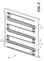
- the haptic feedback layer 800includes plurality of oppositely facing, interlaced cantilever beams 801 , 802 .
- each of the plurality of oppositely facing, interlaced cantilever beams 801 , 802is coupled to the chassis 806 with a coupling member, e.g., coupling member 807 .
- the coupling member 807comprises a U-shaped aperture 808 .
- Such an aperture 808can be shaped to tune and alter the cantilever action of each of the plurality of oppositely facing, interlaced cantilever beams 801 , 802 .
- FIG. 9illustrated therein is an exemplary control signal for driving piezoelectric actuators so as to provide a popple button sensation feedback.
- a characterisic of the acceleration profile 901is high peak acceleration, 1 ⁇ 100 g, in a relatively short time period ( ⁇ 10 ms). The high frequency component in the acceleration curve associates with sound accompanying the tactile click feel.
- Embodiments of the inventionprovide a user interface system that produces an intense haptic response that is substantially uniform throughout its output region.
- the plurality of cantilever beamswork to “average” the piezoelectric impulse induced within the chassis by combining it with a similar one from an opposing orientation.
- the support beams, where used,can provide additional strength and rigidity to the overall system for modest loads without dampening out the displacement effects of the cantilevers beams.
- the use of opposing cantilever beamsprovides a degree of system redundancy in the event that one of the piezoelectric actuators becomes damaged.
Landscapes
- Engineering & Computer Science (AREA)
- General Engineering & Computer Science (AREA)
- Theoretical Computer Science (AREA)
- Human Computer Interaction (AREA)
- Physics & Mathematics (AREA)
- General Physics & Mathematics (AREA)
- Computer Hardware Design (AREA)
- User Interface Of Digital Computer (AREA)
- Position Input By Displaying (AREA)
Abstract
Description
Claims (20)
Priority Applications (6)
| Application Number | Priority Date | Filing Date | Title |
|---|---|---|---|
| US12/038,279US8395587B2 (en) | 2007-12-21 | 2008-02-27 | Haptic response apparatus for an electronic device |
| CN2008801220389ACN101903848B (en) | 2007-12-21 | 2008-12-02 | Haptic response apparatus for an electronic device |
| PCT/US2008/085215WO2009085532A1 (en) | 2007-12-21 | 2008-12-02 | Haptic response apparatus for an electronic device |
| EP08868922.9AEP2235607B1 (en) | 2007-12-21 | 2008-12-02 | Haptic response apparatus for an electronic device |
| RU2010130295/08ARU2451324C2 (en) | 2007-12-21 | 2008-12-02 | Haptic response apparatus for electronic device |
| KR1020107013600AKR101178638B1 (en) | 2007-12-21 | 2008-12-02 | Haptic response apparatus for an electronic device |
Applications Claiming Priority (2)
| Application Number | Priority Date | Filing Date | Title |
|---|---|---|---|
| US1611107P | 2007-12-21 | 2007-12-21 | |
| US12/038,279US8395587B2 (en) | 2007-12-21 | 2008-02-27 | Haptic response apparatus for an electronic device |
Publications (2)
| Publication Number | Publication Date |
|---|---|
| US20090160763A1 US20090160763A1 (en) | 2009-06-25 |
| US8395587B2true US8395587B2 (en) | 2013-03-12 |
Family
ID=40787987
Family Applications (1)
| Application Number | Title | Priority Date | Filing Date |
|---|---|---|---|
| US12/038,279Expired - Fee RelatedUS8395587B2 (en) | 2007-12-21 | 2008-02-27 | Haptic response apparatus for an electronic device |
Country Status (6)
| Country | Link |
|---|---|
| US (1) | US8395587B2 (en) |
| EP (1) | EP2235607B1 (en) |
| KR (1) | KR101178638B1 (en) |
| CN (1) | CN101903848B (en) |
| RU (1) | RU2451324C2 (en) |
| WO (1) | WO2009085532A1 (en) |
Cited By (68)
| Publication number | Priority date | Publication date | Assignee | Title |
|---|---|---|---|---|
| US20120229196A1 (en)* | 2011-03-10 | 2012-09-13 | Hiroshi Shigetaka | Capacitance type input device |
| US8547339B2 (en) | 2008-01-04 | 2013-10-01 | Tactus Technology, Inc. | System and methods for raised touch screens |
| US8553005B2 (en) | 2008-01-04 | 2013-10-08 | Tactus Technology, Inc. | User interface system |
| US8570295B2 (en) | 2008-01-04 | 2013-10-29 | Tactus Technology, Inc. | User interface system |
| US8587548B2 (en) | 2009-07-03 | 2013-11-19 | Tactus Technology, Inc. | Method for adjusting the user interface of a device |
| US8619035B2 (en) | 2010-02-10 | 2013-12-31 | Tactus Technology, Inc. | Method for assisting user input to a device |
| US20140230575A1 (en)* | 2013-02-17 | 2014-08-21 | Microsoft Corporation | Piezo-actuated virtual buttons for touch surfaces |
| US8922503B2 (en) | 2008-01-04 | 2014-12-30 | Tactus Technology, Inc. | User interface system |
| US8922502B2 (en) | 2008-01-04 | 2014-12-30 | Tactus Technology, Inc. | User interface system |
| US8922510B2 (en) | 2008-01-04 | 2014-12-30 | Tactus Technology, Inc. | User interface system |
| US8928621B2 (en) | 2008-01-04 | 2015-01-06 | Tactus Technology, Inc. | User interface system and method |
| US8947383B2 (en) | 2008-01-04 | 2015-02-03 | Tactus Technology, Inc. | User interface system and method |
| US8970403B2 (en) | 2008-01-04 | 2015-03-03 | Tactus Technology, Inc. | Method for actuating a tactile interface layer |
| US9019228B2 (en) | 2008-01-04 | 2015-04-28 | Tactus Technology, Inc. | User interface system |
| US9035899B2 (en) | 2009-07-30 | 2015-05-19 | Immersion Corporation | Systems and methods for piezo-based haptic feedback |
| US9052790B2 (en) | 2008-01-04 | 2015-06-09 | Tactus Technology, Inc. | User interface and methods |
| US9063627B2 (en) | 2008-01-04 | 2015-06-23 | Tactus Technology, Inc. | User interface and methods |
| US9075525B2 (en) | 2008-01-04 | 2015-07-07 | Tactus Technology, Inc. | User interface system |
| US9098141B2 (en) | 2008-01-04 | 2015-08-04 | Tactus Technology, Inc. | User interface system |
| US9116617B2 (en) | 2009-07-03 | 2015-08-25 | Tactus Technology, Inc. | User interface enhancement system |
| US9239623B2 (en) | 2010-01-05 | 2016-01-19 | Tactus Technology, Inc. | Dynamic tactile interface |
| US9274612B2 (en) | 2008-01-04 | 2016-03-01 | Tactus Technology, Inc. | User interface system |
| US9280224B2 (en) | 2012-09-24 | 2016-03-08 | Tactus Technology, Inc. | Dynamic tactile interface and methods |
| US9298261B2 (en) | 2008-01-04 | 2016-03-29 | Tactus Technology, Inc. | Method for actuating a tactile interface layer |
| US9372565B2 (en) | 2008-01-04 | 2016-06-21 | Tactus Technology, Inc. | Dynamic tactile interface |
| US9405417B2 (en) | 2012-09-24 | 2016-08-02 | Tactus Technology, Inc. | Dynamic tactile interface and methods |
| US9423875B2 (en) | 2008-01-04 | 2016-08-23 | Tactus Technology, Inc. | Dynamic tactile interface with exhibiting optical dispersion characteristics |
| US9448631B2 (en) | 2013-12-31 | 2016-09-20 | Microsoft Technology Licensing, Llc | Input device haptics and pressure sensing |
| US9477308B2 (en) | 2008-01-04 | 2016-10-25 | Tactus Technology, Inc. | User interface system |
| US9501912B1 (en) | 2014-01-27 | 2016-11-22 | Apple Inc. | Haptic feedback device with a rotating mass of variable eccentricity |
| US9552065B2 (en) | 2008-01-04 | 2017-01-24 | Tactus Technology, Inc. | Dynamic tactile interface |
| US9557915B2 (en) | 2008-01-04 | 2017-01-31 | Tactus Technology, Inc. | Dynamic tactile interface |
| US9557813B2 (en) | 2013-06-28 | 2017-01-31 | Tactus Technology, Inc. | Method for reducing perceived optical distortion |
| US9564029B2 (en) | 2014-09-02 | 2017-02-07 | Apple Inc. | Haptic notifications |
| US9588683B2 (en) | 2008-01-04 | 2017-03-07 | Tactus Technology, Inc. | Dynamic tactile interface |
| US9588684B2 (en) | 2009-01-05 | 2017-03-07 | Tactus Technology, Inc. | Tactile interface for a computing device |
| US9608506B2 (en) | 2014-06-03 | 2017-03-28 | Apple Inc. | Linear actuator |
| US9612659B2 (en) | 2008-01-04 | 2017-04-04 | Tactus Technology, Inc. | User interface system |
| US9640048B2 (en) | 2009-09-30 | 2017-05-02 | Apple Inc. | Self adapting haptic device |
| US9652040B2 (en) | 2013-08-08 | 2017-05-16 | Apple Inc. | Sculpted waveforms with no or reduced unforced response |
| US9720501B2 (en) | 2008-01-04 | 2017-08-01 | Tactus Technology, Inc. | Dynamic tactile interface |
| US9760172B2 (en) | 2008-01-04 | 2017-09-12 | Tactus Technology, Inc. | Dynamic tactile interface |
| US9779592B1 (en) | 2013-09-26 | 2017-10-03 | Apple Inc. | Geared haptic feedback element |
| US9886093B2 (en) | 2013-09-27 | 2018-02-06 | Apple Inc. | Band with haptic actuators |
| US9911553B2 (en) | 2012-09-28 | 2018-03-06 | Apple Inc. | Ultra low travel keyboard |
| US9928950B2 (en) | 2013-09-27 | 2018-03-27 | Apple Inc. | Polarized magnetic actuators for haptic response |
| US10013058B2 (en) | 2010-09-21 | 2018-07-03 | Apple Inc. | Touch-based user interface with haptic feedback |
| US10039080B2 (en) | 2016-03-04 | 2018-07-31 | Apple Inc. | Situationally-aware alerts |
| US10061385B2 (en) | 2016-01-22 | 2018-08-28 | Microsoft Technology Licensing, Llc | Haptic feedback for a touch input device |
| US10120446B2 (en) | 2010-11-19 | 2018-11-06 | Apple Inc. | Haptic input device |
| US10126817B2 (en) | 2013-09-29 | 2018-11-13 | Apple Inc. | Devices and methods for creating haptic effects |
| US10236760B2 (en) | 2013-09-30 | 2019-03-19 | Apple Inc. | Magnetic actuators for haptic response |
| US10268272B2 (en) | 2016-03-31 | 2019-04-23 | Apple Inc. | Dampening mechanical modes of a haptic actuator using a delay |
| US10276001B2 (en) | 2013-12-10 | 2019-04-30 | Apple Inc. | Band attachment mechanism with haptic response |
| US10353467B2 (en) | 2015-03-06 | 2019-07-16 | Apple Inc. | Calibration of haptic devices |
| US10459521B2 (en) | 2013-10-22 | 2019-10-29 | Apple Inc. | Touch surface for simulating materials |
| US10481691B2 (en) | 2015-04-17 | 2019-11-19 | Apple Inc. | Contracting and elongating materials for providing input and output for an electronic device |
| US10545604B2 (en) | 2014-04-21 | 2020-01-28 | Apple Inc. | Apportionment of forces for multi-touch input devices of electronic devices |
| US10564724B1 (en)* | 2016-09-20 | 2020-02-18 | Apple Inc. | Touch-based input device with haptic feedback |
| US10566888B2 (en) | 2015-09-08 | 2020-02-18 | Apple Inc. | Linear actuators for use in electronic devices |
| US10599223B1 (en) | 2018-09-28 | 2020-03-24 | Apple Inc. | Button providing force sensing and/or haptic output |
| US10622538B2 (en) | 2017-07-18 | 2020-04-14 | Apple Inc. | Techniques for providing a haptic output and sensing a haptic input using a piezoelectric body |
| US10691211B2 (en) | 2018-09-28 | 2020-06-23 | Apple Inc. | Button providing force sensing and/or haptic output |
| US10775853B2 (en) | 2018-10-16 | 2020-09-15 | Texas Instruments Incorporated | Secondary back surface touch sensor for handheld devices |
| US11150734B2 (en) | 2016-09-21 | 2021-10-19 | Apple Inc. | Haptic structure for providing localized haptic output |
| US11380470B2 (en) | 2019-09-24 | 2022-07-05 | Apple Inc. | Methods to control force in reluctance actuators based on flux related parameters |
| US11809631B2 (en) | 2021-09-21 | 2023-11-07 | Apple Inc. | Reluctance haptic engine for an electronic device |
| US11977683B2 (en) | 2021-03-12 | 2024-05-07 | Apple Inc. | Modular systems configured to provide localized haptic feedback using inertial actuators |
Families Citing this family (45)
| Publication number | Priority date | Publication date | Assignee | Title |
|---|---|---|---|---|
| US20090002328A1 (en)* | 2007-06-26 | 2009-01-01 | Immersion Corporation, A Delaware Corporation | Method and apparatus for multi-touch tactile touch panel actuator mechanisms |
| US8248277B2 (en)* | 2007-07-06 | 2012-08-21 | Pacinian Corporation | Haptic keyboard systems and methods |
| US7741979B2 (en)* | 2007-07-06 | 2010-06-22 | Pacinian Corporation | Haptic keyboard systems and methods |
| US8199033B2 (en)* | 2007-07-06 | 2012-06-12 | Pacinian Corporation | Haptic keyboard systems and methods |
| US8310444B2 (en)* | 2008-01-29 | 2012-11-13 | Pacinian Corporation | Projected field haptic actuation |
| WO2009102992A1 (en)* | 2008-02-15 | 2009-08-20 | Pacinian Corporation | Keyboard adaptive haptic response |
| US8203531B2 (en)* | 2008-03-14 | 2012-06-19 | Pacinian Corporation | Vector-specific haptic feedback |
| US20100089735A1 (en)* | 2008-04-17 | 2010-04-15 | Minebea Co., Ltd. | Haptic keyboard apparatus and method |
| US8174372B2 (en)* | 2008-06-26 | 2012-05-08 | Immersion Corporation | Providing haptic feedback on a touch surface |
| US20100201652A1 (en)* | 2009-02-12 | 2010-08-12 | Sony Ericsson Mobile Communications Ab | Embedded piezoelectric elements in touch panels |
| US9024907B2 (en)* | 2009-04-03 | 2015-05-05 | Synaptics Incorporated | Input device with capacitive force sensor and method for constructing the same |
| KR101133348B1 (en)* | 2009-10-12 | 2012-04-09 | 삼성전기주식회사 | Haptic Feedback Devices and Electronics |
| US9870053B2 (en)* | 2010-02-08 | 2018-01-16 | Immersion Corporation | Systems and methods for haptic feedback using laterally driven piezoelectric actuators |
| US9057653B2 (en) | 2010-05-11 | 2015-06-16 | Synaptics Incorporated | Input device with force sensing |
| US9965094B2 (en) | 2011-01-24 | 2018-05-08 | Microsoft Technology Licensing, Llc | Contact geometry tests |
| US8988087B2 (en) | 2011-01-24 | 2015-03-24 | Microsoft Technology Licensing, Llc | Touchscreen testing |
| US8982061B2 (en) | 2011-02-12 | 2015-03-17 | Microsoft Technology Licensing, Llc | Angular contact geometry |
| US9542092B2 (en) | 2011-02-12 | 2017-01-10 | Microsoft Technology Licensing, Llc | Prediction-based touch contact tracking |
| US8773377B2 (en) | 2011-03-04 | 2014-07-08 | Microsoft Corporation | Multi-pass touch contact tracking |
| US9478067B1 (en)* | 2011-04-08 | 2016-10-25 | Amazon Technologies, Inc. | Augmented reality environment with secondary sensory feedback |
| US9557857B2 (en) | 2011-04-26 | 2017-01-31 | Synaptics Incorporated | Input device with force sensing and haptic response |
| US8913019B2 (en) | 2011-07-14 | 2014-12-16 | Microsoft Corporation | Multi-finger detection and component resolution |
| US9378389B2 (en) | 2011-09-09 | 2016-06-28 | Microsoft Technology Licensing, Llc | Shared item account selection |
| US9748952B2 (en) | 2011-09-21 | 2017-08-29 | Synaptics Incorporated | Input device with integrated deformable electrode structure for force sensing |
| US9041418B2 (en) | 2011-10-25 | 2015-05-26 | Synaptics Incorporated | Input device with force sensing |
| CN102437781B (en)* | 2011-10-28 | 2016-01-20 | 北京航空航天大学 | Based on distributed piezoelectric actuator Active Vibration Control circuit optimization structure and method |
| US9785281B2 (en) | 2011-11-09 | 2017-10-10 | Microsoft Technology Licensing, Llc. | Acoustic touch sensitive testing |
| US8914254B2 (en) | 2012-01-31 | 2014-12-16 | Microsoft Corporation | Latency measurement |
| US9317147B2 (en) | 2012-10-24 | 2016-04-19 | Microsoft Technology Licensing, Llc. | Input testing tool |
| CN102929432B (en)* | 2012-11-06 | 2016-07-06 | 瑞声声学科技(深圳)有限公司 | Touch panel system |
| KR102104910B1 (en) | 2013-02-28 | 2020-04-27 | 삼성전자주식회사 | Portable apparatus for providing haptic feedback with an input unit and method therefor |
| US9229592B2 (en) | 2013-03-14 | 2016-01-05 | Synaptics Incorporated | Shear force detection using capacitive sensors |
| JP5849061B2 (en)* | 2013-03-28 | 2016-01-27 | 京セラドキュメントソリューションズ株式会社 | Display input device and image forming apparatus having the same |
| US10120447B2 (en) | 2013-06-24 | 2018-11-06 | Northwestern University | Haptic display with simultaneous sensing and actuation |
| JP6143179B2 (en)* | 2013-06-26 | 2017-06-07 | 株式会社Soken | Operation input device |
| FR3015382B1 (en)* | 2013-12-19 | 2017-01-13 | Dav | CONTROL DEVICE FOR MOTOR VEHICLE AND CONTROL METHOD |
| US10126861B2 (en) | 2015-05-08 | 2018-11-13 | Synaptics Incorporated | Force sensor substrate |
| US10452211B2 (en) | 2016-05-27 | 2019-10-22 | Synaptics Incorporated | Force sensor with uniform response in an axis |
| US10678364B2 (en)* | 2017-03-23 | 2020-06-09 | Immersion Corporation | System for providing sensor and actuation functionality for touch input device |
| US11054932B2 (en)* | 2017-09-06 | 2021-07-06 | Apple Inc. | Electronic device having a touch sensor, force sensor, and haptic actuator in an integrated module |
| US10996755B2 (en)* | 2018-02-28 | 2021-05-04 | Google Llc | Piezoelectric haptic feedback module |
| FR3095875B1 (en)* | 2019-05-07 | 2021-06-04 | Commissariat Energie Atomique | TOUCH INTERFACE OFFERING A VIBROTACTILE FEEDBACK WITH IMPROVED LOCATION |
| WO2022203542A1 (en)* | 2021-03-25 | 2022-09-29 | Артем Игоревич КОГДАНИН | Sensor panel (embodiments) |
| TWI774495B (en)* | 2021-07-29 | 2022-08-11 | 台睿精工股份有限公司 | A tactile feedback device for producing uniform vibration in an effective area |
| TWI773594B (en)* | 2021-11-19 | 2022-08-01 | 台睿精工股份有限公司 | Slim type tactile feedback device |
Citations (34)
| Publication number | Priority date | Publication date | Assignee | Title |
|---|---|---|---|---|
| US5646589A (en) | 1994-12-19 | 1997-07-08 | Lucent Technologies Inc. | Electronic device having selectable alert modes |
| WO1999048083A1 (en) | 1998-03-20 | 1999-09-23 | Active Control Experts, Inc. | Inertial/audio unit and construction |
| US5973441A (en)* | 1996-05-15 | 1999-10-26 | American Research Corporation Of Virginia | Piezoceramic vibrotactile transducer based on pre-compressed arch |
| US6389302B1 (en) | 1999-04-28 | 2002-05-14 | Ericsson Inc. | Methods and apparatus for causing wireless communication devices to vibrate via piezo-ceramic vibrators |
| US6490360B2 (en) | 2000-03-03 | 2002-12-03 | The United States Of America As Represented By The Secretary Of The Navy | Dual bi-laminate polymer audio transducer |
| US20030067449A1 (en) | 2001-10-10 | 2003-04-10 | Smk Corporation | Touch panel input device |
| US20030146673A1 (en)* | 2000-12-01 | 2003-08-07 | Kouji Toda | Ultrasonic touch panel |
| WO2003103065A1 (en) | 2002-05-31 | 2003-12-11 | Motorola Inc., A Corporation Of The State Of Delaware | Manually operable electronic apparatus |
| US20040021663A1 (en) | 2002-06-11 | 2004-02-05 | Akira Suzuki | Information processing method for designating an arbitrary point within a three-dimensional space |
| US6703764B2 (en)* | 2001-09-27 | 2004-03-09 | Samsung Electronics Co., Ltd. | Pointing apparatus using piezoelectric film, method for producing the apparatus, apparatus and method for detecting pointing information thereof |
| US6819316B2 (en)* | 2001-04-17 | 2004-11-16 | 3M Innovative Properties Company | Flexible capacitive touch sensor |
| US20050007342A1 (en)* | 2002-04-25 | 2005-01-13 | Cruz-Hernandez Juan Manuel | Haptic devices having multiple operational modes including at least one resonant mode |
| US20050032559A1 (en) | 2001-10-15 | 2005-02-10 | Hiroshi Sudo | Hinge device and cellular phone using the same |
| US20050057528A1 (en)* | 2003-09-01 | 2005-03-17 | Martin Kleen | Screen having a touch-sensitive user interface for command input |
| KR20050038645A (en) | 2002-08-29 | 2005-04-27 | 소니 가부시끼 가이샤 | Input device and electronic device using the input device |
| US20050208903A1 (en) | 2004-03-17 | 2005-09-22 | Kabushiki Kaisha Toshiba | Mobile phone and vibration control method of mobile phone |
| US20050219372A1 (en) | 2004-04-05 | 2005-10-06 | Casio Computer Co. Ltd. | Moving image capture device, moving image capture control method, and moving image capture control program |
| US6963762B2 (en) | 2001-05-23 | 2005-11-08 | Nokia Corporation | Mobile phone using tactile icons |
| US20050253643A1 (en) | 2002-10-30 | 2005-11-17 | Sony Corporation | Input device and process for manufacturing the same, portable electronic apparatus comprising input device |
| US20060052143A9 (en)* | 2001-11-28 | 2006-03-09 | Juhani Tuovinen | Piezoelectric user interface |
| US20060172706A1 (en) | 2005-01-31 | 2006-08-03 | Research In Motion Limited | User hand detection for wireless devices |
| US7089793B2 (en) | 2003-03-20 | 2006-08-15 | Ngk Insulators, Ltd. | Method and system of exciting a driving vibration in a vibrator |
| US20060187215A1 (en) | 1998-06-23 | 2006-08-24 | Immersion Corporation | Haptic feedback for touchpads and other touch controls |
| US7098897B2 (en)* | 2003-06-30 | 2006-08-29 | Motorola, Inc. | Touch screen assembly and display for an electronic device |
| US20060208614A1 (en) | 2002-02-15 | 2006-09-21 | Siemens Technology-To-Business Center Llc | Small piezoelectric air pumps with unobstructed airflow |
| US20070037605A1 (en) | 2000-08-29 | 2007-02-15 | Logan James D | Methods and apparatus for controlling cellular and portable phones |
| US20070066274A1 (en) | 2005-09-16 | 2007-03-22 | Lg Electronics Inc. | Antenna integrated speaker assembly, manufacturing method thereof, and wireless communication device having the same |
| US20070103449A1 (en) | 2005-11-08 | 2007-05-10 | Nokia Corporation | Cost efficient element for combined piezo sensor and actuator in robust and small touch screen realization and method for operation thereof |
| US7216962B2 (en) | 2003-06-25 | 2007-05-15 | Seiko Epson Corporation | Ink jet recording head and ink jet printer with piezoelectric element |
| US7265562B2 (en)* | 2003-02-04 | 2007-09-04 | Microfabrica Inc. | Cantilever microprobes for contacting electronic components and methods for making such probes |
| US20080100568A1 (en)* | 2006-10-30 | 2008-05-01 | Koch Paul B | Electronic device providing tactile feedback |
| US20080207254A1 (en)* | 2007-02-27 | 2008-08-28 | Pierce Paul M | Multimodal Adaptive User Interface for a Portable Electronic Device |
| US20090072768A1 (en) | 2007-09-17 | 2009-03-19 | Murray Matthew J | Use of an accelerometer to control vibrator performance |
| US8036699B2 (en) | 2005-03-01 | 2011-10-11 | Nec Corporation | Audio output device, its alarm output control method, and its control program |
Family Cites Families (1)
| Publication number | Priority date | Publication date | Assignee | Title |
|---|---|---|---|---|
| DE102005011633A1 (en)* | 2005-03-14 | 2006-09-21 | Siemens Ag | Touch screen with haptic feedback |
- 2008
- 2008-02-27USUS12/038,279patent/US8395587B2/ennot_activeExpired - Fee Related
- 2008-12-02KRKR1020107013600Apatent/KR101178638B1/enactiveActive
- 2008-12-02RURU2010130295/08Apatent/RU2451324C2/ennot_activeIP Right Cessation
- 2008-12-02EPEP08868922.9Apatent/EP2235607B1/enactiveActive
- 2008-12-02WOPCT/US2008/085215patent/WO2009085532A1/enactiveApplication Filing
- 2008-12-02CNCN2008801220389Apatent/CN101903848B/enactiveActive
Patent Citations (34)
| Publication number | Priority date | Publication date | Assignee | Title |
|---|---|---|---|---|
| US5646589A (en) | 1994-12-19 | 1997-07-08 | Lucent Technologies Inc. | Electronic device having selectable alert modes |
| US5973441A (en)* | 1996-05-15 | 1999-10-26 | American Research Corporation Of Virginia | Piezoceramic vibrotactile transducer based on pre-compressed arch |
| WO1999048083A1 (en) | 1998-03-20 | 1999-09-23 | Active Control Experts, Inc. | Inertial/audio unit and construction |
| US20060187215A1 (en) | 1998-06-23 | 2006-08-24 | Immersion Corporation | Haptic feedback for touchpads and other touch controls |
| US6389302B1 (en) | 1999-04-28 | 2002-05-14 | Ericsson Inc. | Methods and apparatus for causing wireless communication devices to vibrate via piezo-ceramic vibrators |
| US6490360B2 (en) | 2000-03-03 | 2002-12-03 | The United States Of America As Represented By The Secretary Of The Navy | Dual bi-laminate polymer audio transducer |
| US20070037605A1 (en) | 2000-08-29 | 2007-02-15 | Logan James D | Methods and apparatus for controlling cellular and portable phones |
| US20030146673A1 (en)* | 2000-12-01 | 2003-08-07 | Kouji Toda | Ultrasonic touch panel |
| US6819316B2 (en)* | 2001-04-17 | 2004-11-16 | 3M Innovative Properties Company | Flexible capacitive touch sensor |
| US6963762B2 (en) | 2001-05-23 | 2005-11-08 | Nokia Corporation | Mobile phone using tactile icons |
| US6703764B2 (en)* | 2001-09-27 | 2004-03-09 | Samsung Electronics Co., Ltd. | Pointing apparatus using piezoelectric film, method for producing the apparatus, apparatus and method for detecting pointing information thereof |
| US20030067449A1 (en) | 2001-10-10 | 2003-04-10 | Smk Corporation | Touch panel input device |
| US20050032559A1 (en) | 2001-10-15 | 2005-02-10 | Hiroshi Sudo | Hinge device and cellular phone using the same |
| US20060052143A9 (en)* | 2001-11-28 | 2006-03-09 | Juhani Tuovinen | Piezoelectric user interface |
| US20060208614A1 (en) | 2002-02-15 | 2006-09-21 | Siemens Technology-To-Business Center Llc | Small piezoelectric air pumps with unobstructed airflow |
| US20050007342A1 (en)* | 2002-04-25 | 2005-01-13 | Cruz-Hernandez Juan Manuel | Haptic devices having multiple operational modes including at least one resonant mode |
| WO2003103065A1 (en) | 2002-05-31 | 2003-12-11 | Motorola Inc., A Corporation Of The State Of Delaware | Manually operable electronic apparatus |
| US20040021663A1 (en) | 2002-06-11 | 2004-02-05 | Akira Suzuki | Information processing method for designating an arbitrary point within a three-dimensional space |
| KR20050038645A (en) | 2002-08-29 | 2005-04-27 | 소니 가부시끼 가이샤 | Input device and electronic device using the input device |
| US20050253643A1 (en) | 2002-10-30 | 2005-11-17 | Sony Corporation | Input device and process for manufacturing the same, portable electronic apparatus comprising input device |
| US7265562B2 (en)* | 2003-02-04 | 2007-09-04 | Microfabrica Inc. | Cantilever microprobes for contacting electronic components and methods for making such probes |
| US7089793B2 (en) | 2003-03-20 | 2006-08-15 | Ngk Insulators, Ltd. | Method and system of exciting a driving vibration in a vibrator |
| US7216962B2 (en) | 2003-06-25 | 2007-05-15 | Seiko Epson Corporation | Ink jet recording head and ink jet printer with piezoelectric element |
| US7098897B2 (en)* | 2003-06-30 | 2006-08-29 | Motorola, Inc. | Touch screen assembly and display for an electronic device |
| US20050057528A1 (en)* | 2003-09-01 | 2005-03-17 | Martin Kleen | Screen having a touch-sensitive user interface for command input |
| US20050208903A1 (en) | 2004-03-17 | 2005-09-22 | Kabushiki Kaisha Toshiba | Mobile phone and vibration control method of mobile phone |
| US20050219372A1 (en) | 2004-04-05 | 2005-10-06 | Casio Computer Co. Ltd. | Moving image capture device, moving image capture control method, and moving image capture control program |
| US20060172706A1 (en) | 2005-01-31 | 2006-08-03 | Research In Motion Limited | User hand detection for wireless devices |
| US8036699B2 (en) | 2005-03-01 | 2011-10-11 | Nec Corporation | Audio output device, its alarm output control method, and its control program |
| US20070066274A1 (en) | 2005-09-16 | 2007-03-22 | Lg Electronics Inc. | Antenna integrated speaker assembly, manufacturing method thereof, and wireless communication device having the same |
| US20070103449A1 (en) | 2005-11-08 | 2007-05-10 | Nokia Corporation | Cost efficient element for combined piezo sensor and actuator in robust and small touch screen realization and method for operation thereof |
| US20080100568A1 (en)* | 2006-10-30 | 2008-05-01 | Koch Paul B | Electronic device providing tactile feedback |
| US20080207254A1 (en)* | 2007-02-27 | 2008-08-28 | Pierce Paul M | Multimodal Adaptive User Interface for a Portable Electronic Device |
| US20090072768A1 (en) | 2007-09-17 | 2009-03-19 | Murray Matthew J | Use of an accelerometer to control vibrator performance |
Non-Patent Citations (1)
| Title |
|---|
| KIPO Notice of Preliminary Rejection (English Translation), Dec. 13, 2011, all pages. |
Cited By (99)
| Publication number | Priority date | Publication date | Assignee | Title |
|---|---|---|---|---|
| US9619030B2 (en) | 2008-01-04 | 2017-04-11 | Tactus Technology, Inc. | User interface system and method |
| US9063627B2 (en) | 2008-01-04 | 2015-06-23 | Tactus Technology, Inc. | User interface and methods |
| US8553005B2 (en) | 2008-01-04 | 2013-10-08 | Tactus Technology, Inc. | User interface system |
| US8570295B2 (en) | 2008-01-04 | 2013-10-29 | Tactus Technology, Inc. | User interface system |
| US9760172B2 (en) | 2008-01-04 | 2017-09-12 | Tactus Technology, Inc. | Dynamic tactile interface |
| US9495055B2 (en) | 2008-01-04 | 2016-11-15 | Tactus Technology, Inc. | User interface and methods |
| US9720501B2 (en) | 2008-01-04 | 2017-08-01 | Tactus Technology, Inc. | Dynamic tactile interface |
| US8717326B2 (en) | 2008-01-04 | 2014-05-06 | Tactus Technology, Inc. | System and methods for raised touch screens |
| US9612659B2 (en) | 2008-01-04 | 2017-04-04 | Tactus Technology, Inc. | User interface system |
| US8922503B2 (en) | 2008-01-04 | 2014-12-30 | Tactus Technology, Inc. | User interface system |
| US8922502B2 (en) | 2008-01-04 | 2014-12-30 | Tactus Technology, Inc. | User interface system |
| US8922510B2 (en) | 2008-01-04 | 2014-12-30 | Tactus Technology, Inc. | User interface system |
| US8928621B2 (en) | 2008-01-04 | 2015-01-06 | Tactus Technology, Inc. | User interface system and method |
| US8947383B2 (en) | 2008-01-04 | 2015-02-03 | Tactus Technology, Inc. | User interface system and method |
| US8970403B2 (en) | 2008-01-04 | 2015-03-03 | Tactus Technology, Inc. | Method for actuating a tactile interface layer |
| US9019228B2 (en) | 2008-01-04 | 2015-04-28 | Tactus Technology, Inc. | User interface system |
| US9035898B2 (en) | 2008-01-04 | 2015-05-19 | Tactus Technology, Inc. | System and methods for raised touch screens |
| US9626059B2 (en) | 2008-01-04 | 2017-04-18 | Tactus Technology, Inc. | User interface system |
| US9052790B2 (en) | 2008-01-04 | 2015-06-09 | Tactus Technology, Inc. | User interface and methods |
| US9524025B2 (en) | 2008-01-04 | 2016-12-20 | Tactus Technology, Inc. | User interface system and method |
| US9075525B2 (en) | 2008-01-04 | 2015-07-07 | Tactus Technology, Inc. | User interface system |
| US9098141B2 (en) | 2008-01-04 | 2015-08-04 | Tactus Technology, Inc. | User interface system |
| US9477308B2 (en) | 2008-01-04 | 2016-10-25 | Tactus Technology, Inc. | User interface system |
| US9207795B2 (en) | 2008-01-04 | 2015-12-08 | Tactus Technology, Inc. | User interface system |
| US9229571B2 (en) | 2008-01-04 | 2016-01-05 | Tactus Technology, Inc. | Method for adjusting the user interface of a device |
| US8547339B2 (en) | 2008-01-04 | 2013-10-01 | Tactus Technology, Inc. | System and methods for raised touch screens |
| US9274612B2 (en) | 2008-01-04 | 2016-03-01 | Tactus Technology, Inc. | User interface system |
| US9552065B2 (en) | 2008-01-04 | 2017-01-24 | Tactus Technology, Inc. | Dynamic tactile interface |
| US9298261B2 (en) | 2008-01-04 | 2016-03-29 | Tactus Technology, Inc. | Method for actuating a tactile interface layer |
| US9588683B2 (en) | 2008-01-04 | 2017-03-07 | Tactus Technology, Inc. | Dynamic tactile interface |
| US9372565B2 (en) | 2008-01-04 | 2016-06-21 | Tactus Technology, Inc. | Dynamic tactile interface |
| US9372539B2 (en) | 2008-01-04 | 2016-06-21 | Tactus Technology, Inc. | Method for actuating a tactile interface layer |
| US9557915B2 (en) | 2008-01-04 | 2017-01-31 | Tactus Technology, Inc. | Dynamic tactile interface |
| US9423875B2 (en) | 2008-01-04 | 2016-08-23 | Tactus Technology, Inc. | Dynamic tactile interface with exhibiting optical dispersion characteristics |
| US9430074B2 (en) | 2008-01-04 | 2016-08-30 | Tactus Technology, Inc. | Dynamic tactile interface |
| US9448630B2 (en) | 2008-01-04 | 2016-09-20 | Tactus Technology, Inc. | Method for actuating a tactile interface layer |
| US9588684B2 (en) | 2009-01-05 | 2017-03-07 | Tactus Technology, Inc. | Tactile interface for a computing device |
| US9116617B2 (en) | 2009-07-03 | 2015-08-25 | Tactus Technology, Inc. | User interface enhancement system |
| US8587548B2 (en) | 2009-07-03 | 2013-11-19 | Tactus Technology, Inc. | Method for adjusting the user interface of a device |
| US9035899B2 (en) | 2009-07-30 | 2015-05-19 | Immersion Corporation | Systems and methods for piezo-based haptic feedback |
| US9640048B2 (en) | 2009-09-30 | 2017-05-02 | Apple Inc. | Self adapting haptic device |
| US12094328B2 (en) | 2009-09-30 | 2024-09-17 | Apple Inc. | Device having a camera used to detect visual cues that activate a function of the device |
| US10475300B2 (en) | 2009-09-30 | 2019-11-12 | Apple Inc. | Self adapting haptic device |
| US11605273B2 (en) | 2009-09-30 | 2023-03-14 | Apple Inc. | Self-adapting electronic device |
| US9934661B2 (en) | 2009-09-30 | 2018-04-03 | Apple Inc. | Self adapting haptic device |
| US11043088B2 (en) | 2009-09-30 | 2021-06-22 | Apple Inc. | Self adapting haptic device |
| US9298262B2 (en) | 2010-01-05 | 2016-03-29 | Tactus Technology, Inc. | Dynamic tactile interface |
| US9239623B2 (en) | 2010-01-05 | 2016-01-19 | Tactus Technology, Inc. | Dynamic tactile interface |
| US8619035B2 (en) | 2010-02-10 | 2013-12-31 | Tactus Technology, Inc. | Method for assisting user input to a device |
| US10013058B2 (en) | 2010-09-21 | 2018-07-03 | Apple Inc. | Touch-based user interface with haptic feedback |
| US10120446B2 (en) | 2010-11-19 | 2018-11-06 | Apple Inc. | Haptic input device |
| US20120229196A1 (en)* | 2011-03-10 | 2012-09-13 | Hiroshi Shigetaka | Capacitance type input device |
| US8575995B2 (en)* | 2011-03-10 | 2013-11-05 | Alps Electric Co., Ltd. | Capacitance type input device |
| US9280224B2 (en) | 2012-09-24 | 2016-03-08 | Tactus Technology, Inc. | Dynamic tactile interface and methods |
| US9405417B2 (en) | 2012-09-24 | 2016-08-02 | Tactus Technology, Inc. | Dynamic tactile interface and methods |
| US9911553B2 (en) | 2012-09-28 | 2018-03-06 | Apple Inc. | Ultra low travel keyboard |
| US9997306B2 (en) | 2012-09-28 | 2018-06-12 | Apple Inc. | Ultra low travel keyboard |
| US10578499B2 (en)* | 2013-02-17 | 2020-03-03 | Microsoft Technology Licensing, Llc | Piezo-actuated virtual buttons for touch surfaces |
| US20140230575A1 (en)* | 2013-02-17 | 2014-08-21 | Microsoft Corporation | Piezo-actuated virtual buttons for touch surfaces |
| US9557813B2 (en) | 2013-06-28 | 2017-01-31 | Tactus Technology, Inc. | Method for reducing perceived optical distortion |
| US9652040B2 (en) | 2013-08-08 | 2017-05-16 | Apple Inc. | Sculpted waveforms with no or reduced unforced response |
| US9779592B1 (en) | 2013-09-26 | 2017-10-03 | Apple Inc. | Geared haptic feedback element |
| US9886093B2 (en) | 2013-09-27 | 2018-02-06 | Apple Inc. | Band with haptic actuators |
| US9928950B2 (en) | 2013-09-27 | 2018-03-27 | Apple Inc. | Polarized magnetic actuators for haptic response |
| US10126817B2 (en) | 2013-09-29 | 2018-11-13 | Apple Inc. | Devices and methods for creating haptic effects |
| US10236760B2 (en) | 2013-09-30 | 2019-03-19 | Apple Inc. | Magnetic actuators for haptic response |
| US10651716B2 (en) | 2013-09-30 | 2020-05-12 | Apple Inc. | Magnetic actuators for haptic response |
| US10459521B2 (en) | 2013-10-22 | 2019-10-29 | Apple Inc. | Touch surface for simulating materials |
| US10276001B2 (en) | 2013-12-10 | 2019-04-30 | Apple Inc. | Band attachment mechanism with haptic response |
| US9448631B2 (en) | 2013-12-31 | 2016-09-20 | Microsoft Technology Licensing, Llc | Input device haptics and pressure sensing |
| US10359848B2 (en) | 2013-12-31 | 2019-07-23 | Microsoft Technology Licensing, Llc | Input device haptics and pressure sensing |
| US9501912B1 (en) | 2014-01-27 | 2016-11-22 | Apple Inc. | Haptic feedback device with a rotating mass of variable eccentricity |
| US10545604B2 (en) | 2014-04-21 | 2020-01-28 | Apple Inc. | Apportionment of forces for multi-touch input devices of electronic devices |
| US10069392B2 (en) | 2014-06-03 | 2018-09-04 | Apple Inc. | Linear vibrator with enclosed mass assembly structure |
| US9608506B2 (en) | 2014-06-03 | 2017-03-28 | Apple Inc. | Linear actuator |
| US9564029B2 (en) | 2014-09-02 | 2017-02-07 | Apple Inc. | Haptic notifications |
| US10490035B2 (en) | 2014-09-02 | 2019-11-26 | Apple Inc. | Haptic notifications |
| US9830782B2 (en) | 2014-09-02 | 2017-11-28 | Apple Inc. | Haptic notifications |
| US10353467B2 (en) | 2015-03-06 | 2019-07-16 | Apple Inc. | Calibration of haptic devices |
| US10481691B2 (en) | 2015-04-17 | 2019-11-19 | Apple Inc. | Contracting and elongating materials for providing input and output for an electronic device |
| US11402911B2 (en) | 2015-04-17 | 2022-08-02 | Apple Inc. | Contracting and elongating materials for providing input and output for an electronic device |
| US10566888B2 (en) | 2015-09-08 | 2020-02-18 | Apple Inc. | Linear actuators for use in electronic devices |
| US10061385B2 (en) | 2016-01-22 | 2018-08-28 | Microsoft Technology Licensing, Llc | Haptic feedback for a touch input device |
| US10609677B2 (en) | 2016-03-04 | 2020-03-31 | Apple Inc. | Situationally-aware alerts |
| US10039080B2 (en) | 2016-03-04 | 2018-07-31 | Apple Inc. | Situationally-aware alerts |
| US10809805B2 (en) | 2016-03-31 | 2020-10-20 | Apple Inc. | Dampening mechanical modes of a haptic actuator using a delay |
| US10268272B2 (en) | 2016-03-31 | 2019-04-23 | Apple Inc. | Dampening mechanical modes of a haptic actuator using a delay |
| US10564724B1 (en)* | 2016-09-20 | 2020-02-18 | Apple Inc. | Touch-based input device with haptic feedback |
| US11360560B2 (en)* | 2016-09-20 | 2022-06-14 | Apple Inc. | Touch-based input device with haptic feedback |
| US11150734B2 (en) | 2016-09-21 | 2021-10-19 | Apple Inc. | Haptic structure for providing localized haptic output |
| US10622538B2 (en) | 2017-07-18 | 2020-04-14 | Apple Inc. | Techniques for providing a haptic output and sensing a haptic input using a piezoelectric body |
| US10599223B1 (en) | 2018-09-28 | 2020-03-24 | Apple Inc. | Button providing force sensing and/or haptic output |
| US10691211B2 (en) | 2018-09-28 | 2020-06-23 | Apple Inc. | Button providing force sensing and/or haptic output |
| US11237603B2 (en) | 2018-10-16 | 2022-02-01 | Texas Instruments Incorporated | Secondary back surface touch sensor for handheld devices |
| US10775853B2 (en) | 2018-10-16 | 2020-09-15 | Texas Instruments Incorporated | Secondary back surface touch sensor for handheld devices |
| US11380470B2 (en) | 2019-09-24 | 2022-07-05 | Apple Inc. | Methods to control force in reluctance actuators based on flux related parameters |
| US11763971B2 (en) | 2019-09-24 | 2023-09-19 | Apple Inc. | Methods to control force in reluctance actuators based on flux related parameters |
| US11977683B2 (en) | 2021-03-12 | 2024-05-07 | Apple Inc. | Modular systems configured to provide localized haptic feedback using inertial actuators |
| US11809631B2 (en) | 2021-09-21 | 2023-11-07 | Apple Inc. | Reluctance haptic engine for an electronic device |
Also Published As
| Publication number | Publication date |
|---|---|
| WO2009085532A1 (en) | 2009-07-09 |
| RU2010130295A (en) | 2012-01-27 |
| CN101903848B (en) | 2012-11-14 |
| EP2235607A1 (en) | 2010-10-06 |
| RU2451324C2 (en) | 2012-05-20 |
| KR20100095608A (en) | 2010-08-31 |
| CN101903848A (en) | 2010-12-01 |
| KR101178638B1 (en) | 2012-09-07 |
| US20090160763A1 (en) | 2009-06-25 |
| EP2235607B1 (en) | 2018-08-01 |
Similar Documents
| Publication | Publication Date | Title |
|---|---|---|
| US8395587B2 (en) | Haptic response apparatus for an electronic device | |
| JP7138678B2 (en) | Haptic structures for providing localized haptic output | |
| US7468573B2 (en) | Method of providing tactile feedback | |
| US20200125174A1 (en) | Tactile feedback device and electronic device equipped with said tactile feedback device | |
| EP3021201B1 (en) | Touch panel assembly with haptic effects | |
| CN100430874C (en) | Input/output device and electronic device using the same | |
| US8339250B2 (en) | Electronic device with localized haptic response | |
| US7579758B2 (en) | Substrate supporting vibration structure, input device having haptic function, and electronic device | |
| US20080100568A1 (en) | Electronic device providing tactile feedback | |
| JP4910726B2 (en) | Touch panel display device, manufacturing method thereof, and electronic device | |
| US20100053087A1 (en) | Touch sensors with tactile feedback | |
| US20110261021A1 (en) | Transparent composite piezoelectric combined touch sensor and haptic actuator | |
| US20080202824A1 (en) | Tilting Touch Control Panel | |
| WO2006022140A1 (en) | Input device | |
| CN109326221B (en) | Display device and tactile feedback display method for display device | |
| US8976012B2 (en) | Touch panel assembly with haptic effects and method of manufacturuing thereof | |
| CN102812418A (en) | touch display device | |
| JP4163045B2 (en) | Coordinate input device | |
| JP2012108949A (en) | Substrate supporting vibration structure, input device with tactile function, and electronic device | |
| JP2013012148A (en) | Tactile presentation touch panel and electronic equipment using the touch panel | |
| JP2017091324A (en) | Haptic feedback device | |
| TW201212079A (en) | Switch module | |
| JP6334024B2 (en) | Tactile presentation device |
Legal Events
| Date | Code | Title | Description |
|---|---|---|---|
| AS | Assignment | Owner name:MOTOROLA, INC.,ILLINOIS Free format text:ASSIGNMENT OF ASSIGNORS INTEREST;ASSIGNORS:CAUWELS, PATRICK, MR.;ALAMEH, RACHID, MR.;GITZINGER, THOMAS, MR.;REEL/FRAME:020569/0091 Effective date:20080219 Owner name:MOTOROLA, INC., ILLINOIS Free format text:ASSIGNMENT OF ASSIGNORS INTEREST;ASSIGNORS:CAUWELS, PATRICK, MR.;ALAMEH, RACHID, MR.;GITZINGER, THOMAS, MR.;REEL/FRAME:020569/0091 Effective date:20080219 | |
| AS | Assignment | Owner name:MOTOROLA MOBILITY, INC, ILLINOIS Free format text:ASSIGNMENT OF ASSIGNORS INTEREST;ASSIGNOR:MOTOROLA, INC;REEL/FRAME:025673/0558 Effective date:20100731 | |
| AS | Assignment | Owner name:MOTOROLA MOBILITY LLC, ILLINOIS Free format text:ASSIGNMENT OF ASSIGNORS INTEREST;ASSIGNOR:MOTOROLA MOBILITY, INC.;REEL/FRAME:028829/0856 Effective date:20120622 | |
| STCF | Information on status: patent grant | Free format text:PATENTED CASE | |
| AS | Assignment | Owner name:GOOGLE TECHNOLOGY HOLDINGS LLC, CALIFORNIA Free format text:ASSIGNMENT OF ASSIGNORS INTEREST;ASSIGNOR:MOTOROLA MOBILITY LLC;REEL/FRAME:034301/0001 Effective date:20141028 | |
| FPAY | Fee payment | Year of fee payment:4 | |
| FEPP | Fee payment procedure | Free format text:MAINTENANCE FEE REMINDER MAILED (ORIGINAL EVENT CODE: REM.); ENTITY STATUS OF PATENT OWNER: LARGE ENTITY | |
| LAPS | Lapse for failure to pay maintenance fees | Free format text:PATENT EXPIRED FOR FAILURE TO PAY MAINTENANCE FEES (ORIGINAL EVENT CODE: EXP.); ENTITY STATUS OF PATENT OWNER: LARGE ENTITY | |
| STCH | Information on status: patent discontinuation | Free format text:PATENT EXPIRED DUE TO NONPAYMENT OF MAINTENANCE FEES UNDER 37 CFR 1.362 | |
| FP | Lapsed due to failure to pay maintenance fee | Effective date:20210312 |