US8395096B2 - Precision strip heating element - Google Patents
Precision strip heating elementDownload PDFInfo
- Publication number
- US8395096B2 US8395096B2US12/697,719US69771910AUS8395096B2US 8395096 B2US8395096 B2US 8395096B2US 69771910 AUS69771910 AUS 69771910AUS 8395096 B2US8395096 B2US 8395096B2
- Authority
- US
- United States
- Prior art keywords
- heating assembly
- heating element
- segments
- straight segments
- mounting members
- Prior art date
- Legal status (The legal status is an assumption and is not a legal conclusion. Google has not performed a legal analysis and makes no representation as to the accuracy of the status listed.)
- Expired - Fee Related, expires
Links
Images


Classifications
- H—ELECTRICITY
- H05—ELECTRIC TECHNIQUES NOT OTHERWISE PROVIDED FOR
- H05B—ELECTRIC HEATING; ELECTRIC LIGHT SOURCES NOT OTHERWISE PROVIDED FOR; CIRCUIT ARRANGEMENTS FOR ELECTRIC LIGHT SOURCES, IN GENERAL
- H05B3/00—Ohmic-resistance heating
- H05B3/62—Heating elements specially adapted for furnaces
- H—ELECTRICITY
- H01—ELECTRIC ELEMENTS
- H01L—SEMICONDUCTOR DEVICES NOT COVERED BY CLASS H10
- H01L21/00—Processes or apparatus adapted for the manufacture or treatment of semiconductor or solid state devices or of parts thereof
- H01L21/67—Apparatus specially adapted for handling semiconductor or electric solid state devices during manufacture or treatment thereof; Apparatus specially adapted for handling wafers during manufacture or treatment of semiconductor or electric solid state devices or components ; Apparatus not specifically provided for elsewhere
- H01L21/67005—Apparatus not specifically provided for elsewhere
- H01L21/67011—Apparatus for manufacture or treatment
- H01L21/67098—Apparatus for thermal treatment
- H01L21/67109—Apparatus for thermal treatment mainly by convection
- H—ELECTRICITY
- H01—ELECTRIC ELEMENTS
- H01L—SEMICONDUCTOR DEVICES NOT COVERED BY CLASS H10
- H01L21/00—Processes or apparatus adapted for the manufacture or treatment of semiconductor or solid state devices or of parts thereof
- H01L21/67—Apparatus specially adapted for handling semiconductor or electric solid state devices during manufacture or treatment thereof; Apparatus specially adapted for handling wafers during manufacture or treatment of semiconductor or electric solid state devices or components ; Apparatus not specifically provided for elsewhere
- H01L21/67005—Apparatus not specifically provided for elsewhere
- H01L21/67011—Apparatus for manufacture or treatment
- H01L21/67098—Apparatus for thermal treatment
- H01L21/67103—Apparatus for thermal treatment mainly by conduction
- Y—GENERAL TAGGING OF NEW TECHNOLOGICAL DEVELOPMENTS; GENERAL TAGGING OF CROSS-SECTIONAL TECHNOLOGIES SPANNING OVER SEVERAL SECTIONS OF THE IPC; TECHNICAL SUBJECTS COVERED BY FORMER USPC CROSS-REFERENCE ART COLLECTIONS [XRACs] AND DIGESTS
- Y10—TECHNICAL SUBJECTS COVERED BY FORMER USPC
- Y10T—TECHNICAL SUBJECTS COVERED BY FORMER US CLASSIFICATION
- Y10T29/00—Metal working
- Y10T29/49—Method of mechanical manufacture
- Y10T29/49002—Electrical device making
- Y10T29/49082—Resistor making
- Y10T29/49083—Heater type
Definitions
- the present disclosurerelates to heating elements. More particularly, the present disclosure relates to strip heating elements for furnaces, e.g., semiconductor processing furnaces, that have a circuitous path including straight and radiused segments that advantageously accommodates thermal expansion and contraction.
- furnacese.g., semiconductor processing furnaces
- wire patterned elementsare generally limited in operating temperature by virtue of being embedded or semi-embedded in a surrounding medium, such as insulation. Further, wire patterned elements are typically not precision formed, are highly labor intensive and have a medium ratio of surface to mass resulting in fast heating and cooling. For sheet metal heating elements, those formed as primarily square patterns suffer from non-uniformity, while those with continuously curving patterns produce high stresses, both effects being more pronounced when the heating element expands at operating temperatures.
- a substantially uniformly radiating and substantially stress free heating element, even at operating temperatures,would be advantageous.
- a heating elementcan be included in a furnace to improve processing of items.
- a heating elementcan be included in a semiconductor processing furnace for the processing of semiconductor wafers.
- An exemplary heating elementcomprises a continuous planar strip, wherein a path of the continuous strip from a first end to a second end is circuitous and includes a plurality of repeating cycles, each repeating cycle including a plurality of first straight segments, a plurality of second straight segments and a plurality of radiused segments, wherein a length of the first straight segment is greater than a length of the second straight segment, and wherein an angular sum of a single cycle of the circuitous path is greater than 360 degrees.
- An exemplary embodiment of a heating assemblycomprises the heating element mounted in spaced relation to the insulating substrate by a plurality of mounting members.
- An exemplary method of manufacturing a heating assemblycomprises forming a heating element body from a resistance alloy, the heating element body including a continuous planar strip with an emitting surface and a plurality of mounting members, bending the plurality of mounting members out of plane relative to the continuous strip, and inserting the plurality of mounting members into a substrate until an integrated spacer on the mounting members contacts the substrate, wherein a path of the continuous strip from a first end to a second end is circuitous and includes a plurality of repeating cycles, each repeating cycle including a plurality of non-parallel first straight segments, a plurality of second straight segments and a plurality of radiused segments, wherein a length of the first straight segment is greater than a length of the second straight segment, and wherein an angular sum of a single cycle of the circuitous path is greater than 360 degrees.
- Another exemplary method of manufacturing a heating assemblycomprises forming a heating element body from a resistance alloy, the heating element body including a continuous planar strip with an emitting surface, and inserting a plurality of mounting members through an opening integrally formed on the continuous strip and into a substrate until a spacer associated with the mounting members contacts the substrate, wherein a path of the continuous strip from a first end to a second end is circuitous and includes a plurality of repeating cycles, each repeating cycle including a plurality of non-parallel first straight segments, a plurality of second straight segments and a plurality of radiused segments, wherein a length of the first straight segment is greater than a length of the second straight segment, and wherein an angular sum of a single cycle of the circuitous path is greater than 360 degrees.
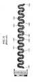
- FIG. 1is a plan, schematic view of an exemplary embodiment of a heating element.
- FIG. 2is a plan, schematic view of a further exemplary embodiment of a heating element.
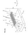
- FIGS. 3A and 3Bshow two different perspective, disassembled views of an exemplary embodiment of a heating assembly.
- FIGS. 4A and 4Bshow two different perspective, disassembled views of another exemplary embodiment of a heating assembly.
- FIGS. 5A to 5Cshow portions of an exemplary embodiment of a heating element, including a first embodiment of a mounting member.
- FIG. 6shows portions of another exemplary embodiment of a heating element, including a second embodiment of a mounting member.
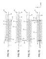
- FIGS. 7A-Dshow, in plan view, several embodiments of a heating element with a combination of types of integrated mounting members and mounting members that are separate elements.
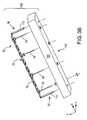
- FIG. 8shows a perspective, disassembled view of an exemplary embodiment of a heating assembly with a combination of types of integrated mounting members and mounting members that are separate elements.
- FIGS. 9A and 9Billustrates the modeled temperature distribution for the exemplary embodiment of a heating element as generally shown in FIG. 1 with a first embodiment of a mounting member ( FIG. 9A ) and with a second embodiment of a mounting member ( FIG. 9B ).
- FIG. 10illustrates the modeled temperature distribution for the exemplary embodiments of a heating element as generally shown in FIG. 2 .
- FIG. 11illustrates the modeled temperature distribution for a prior art heating element.
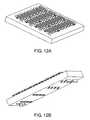
- FIGS. 12A and 12Bshow two different perspective views of an exemplary embodiment of a heating assembly with a plurality of heating elements.
- FIGS. 13A-Eshow examples heating element installations.
- An exemplary embodiment of a heating element 10comprises a continuous planar strip 12 and a plurality of mounting members 14 .
- a path of the continuous strip 12 from a first end 16 to a second end 18is circuitous and includes a plurality of repeating cycles 20 .
- Each repeating cycle 20includes a plurality of non-parallel first straight segments 22 , a plurality of second straight segments 24 and a plurality of radiused segments 26 .
- An angular sum of a single cycle of the circuitous pathis greater than 360 degrees.
- the heating element 10has an emitting surface 30 that generally extends in and generally is contained in a first plane.
- the plurality of first straight segments 22are oriented generally laterally to an axis 32 oriented from the first end 34 of the heating element 10 to a second end 36 of the heating element 10 , e.g., within ⁇ 15 degrees of perpendicular to the axis 32 .
- the plurality of second straight segments 24are oriented generally longitudinally to the axis 32 , e.g., within ⁇ 15 degrees of parallel to the axis 32 .
- any two consecutive first straight segmentsare generally (within ⁇ 15 degrees, alternatively within ⁇ 5 degrees) non-parallel and any two consecutive second straight segments are generally (within ⁇ 15 degrees, alternatively within ⁇ 5 degrees) parallel.
- any two consecutive first straight segments 22are strictly non-parallel and/or any two consecutive any two consecutive second straight segments 24 are strictly parallel.
- the axis 32is conventionally oriented in the X-axis direction.
- a single cycle 20 of the circuitous pathincludes two first straight segments 22 , two second straight segments 24 and four radiused segments 26 .
- the single cycle 20includes two lobes 38 .
- Each lobe 38includes two radiused segments 26 and one second straight segment 24 .
- the one second straight segment 24separates the two radiused segments 26 .
- FIG. 1is a plan, schematic view of an exemplary embodiment of a heating element 10 .
- the cycles 20 in the exemplary embodiment shown in FIG. 1have radiused segments 26 that are continuously radiused from the interface 40 of the radiused segment 26 with a first straight segment 22 to the interface 42 of the radiused segment 26 with a second straight segment 24 .
- the cycle 20is pseudo-sinusoidal relative to the axis 32 , with both a positive portion (positive y-direction with respect to the axis 32 at the centerline) and a negative portion (negative y-direction with respect to the axis 32 at the centerline).
- FIG. 1is a plan, schematic view of an exemplary embodiment of a heating element 10 .
- the cycles 20 in the exemplary embodiment shown in FIG. 1have radiused segments 26 that are continuously radiused from the interface 40 of the radiused segment 26 with a first straight segment 22 to the interface 42 of the radiused segment 26 with a second straight segment 24 .
- FIG. 2is a plan, schematic view of another exemplary embodiment of a heating element 10 .
- the cycles 20 in the exemplary embodiment shown in FIG. 2have radiused segments 26 that include both straight portions and continuously radiused portions from the interface 40 of the radiused segment 26 with a first straight segment 22 to the interface 40 of the radiused segment 26 with a second straight segment 24 .
- the cycle 20is pseudo-square relative to the axis 32 , with the change in path direction in the lobes 38 approaching a squared-off geometry, with both a positive portion and a negative portion.
- the radiused segments 26 in both the pseudo-sinusoidal and the pseudo-square form of the heating element 10have both an interior radius r 1 and an exterior radius R 2 .
- Each radiused segment 26has an associated angle ⁇ that represents the angular change in direction of the circuitous path over the length L r of the radiused segment 26 .
- exemplary embodiments of the radiused segmentshave an angle ⁇ that is between 90 degrees and 135 degrees, i.e., 90° ⁇ 135°, alternatively between 90 degrees and 100 degrees, i.e., 90° ⁇ 100°,
- an angular sum ⁇ of the angles ⁇ of one lobe 38is greater than 180 degrees, preferably greater than 180 degrees to about 200 degrees, more preferably about 185 to about 190 degrees.
- an angular sum of the angles ⁇ associated with a single cycle of the circuitous pathis greater than 360 degrees, preferably greater than 360 degrees to about 400 degrees, more preferably about 370 to about 380 degrees.
- the angular sum ⁇ greater than 180 degreesresults in the two first straight segments 22 adjacent the lobe 38 being non-parallel. This non-parallel relationship can be seen in both FIGS. 1 and 2 .
- the two first straight segments 22 adjacent the lobe 38are separated by a distance D 1 that is greater than a distance D 2 separating the same two first straight segments 22 near the mouth 44 of the opening 46 between lobes 38 in consecutive positive or negative portions.
- D 1is measured at one end of the first straight segments 22 and D 2 is measured at a second end of the first straight segments 22 .
- the circuitous path of the heating element 10can be idealized as a line 50 located at a centerline of the planar heating element 10 .
- FIGS. 1 and 2illustrate the location of the line 50 in the illustrated embodiments.
- This line 50can be used to measure the distance of the circuitous path as well as to measure the angles ⁇ of the radiused segments 26 and the lengths L 1 of first straight segments 22 , the lengths L 2 of the second straight segments 24 and the lengths L r of the radiused segments 26 .
- a length L 1 of the first straight segment 22is greater than a length L 2 of the second straight segment 24 .
- the uniformity of power dissipation of an emitteris higher for a homogenous conductor of uniform cross-section and surface area. It is therefore desirable to maximize the ratio of the length of straight segments to the length of curved segments. It has been determined empirically that the following relationship yields a result with high uniformity, high fill-factor (ratio of substrate surface power to emitter surface power) and minimizes stress in the emitter. Furthermore, this relationship accommodates and controls expansion during transient conditions and over the useful life of the heating element.
- the lengths of the first straight segments 22 , the second straight segments 24 and radiused segments 26 in a single cycleare such that they satisfy the following relationship:
- L 1.Ais the length L 1 of a first first straight segment 22
- L 1.Bis the length L 1 of a second first straight segment 22
- L 2is the length L 2 of a first second straight segment 24
- L 2is the length L 2 of a second second straight segment 24
- L r,ais the length L r of a first radiused segment 26
- L r,bis the length L r of a second radiused segment 26 .
- the relationship aboveis greater than 2.2, further from greater than 2.2. to less than 10.0 or less than 5.0.
- This relationshiprepresents the ratio of the length of straight segments to the length of radiused segments. For a uniform width of the emitter surface, this is also the ratio of surface areas of straight segments to radiused segments. An example of a suitable width is 8 mm. The length is measured at the center of the emitter path, i.e., along line 50 .
- FIGS. 3A-B and 4 A-Bschematically illustrate from two different perspectives, disassembled views of two exemplary embodiments of a heating assembly.
- the heating assembly 100includes a heating element 10 and insulation 102 .
- the insulation 102can be any suitable insulation.
- the insulation 102includes an insulating substrate 104 with an alumina surface layer 106 .
- Other suitable insulation 102includes a substrate formed from an insulating material, preferably a ceramic fiber composite, with an alumina facing layer and a blended ceramic fiber backing layer.
- the heating element 10can be any suitable heating element substantially consistent with the heating element 10 disclosed and described herein, e.g., as in any one of FIGS. 1 and 2 . As shown in FIGS. 3A-B , 4 A-B and 8 the heating element is pseudo-sinusoidal as in FIG. 1 .
- the heating element 10includes a plurality of mounting members 14 .
- the mounting members 14extend from the periphery 60 of the continuous strip 12 at a plurality of locations along the circuitous path.
- the mounting memberscan be located at any suitable position.
- the mounting members 14are on an inner edge of the path proximate a maximum lateral position of the path, i.e., at or near the maximum position of positive and/or negative portions of the lobes 38 .
- the mounting members 14are on an outer edge of the path proximate a maximum lateral position of the path, i.e., at or near the maximum position of positive and/or negative portions of the lobes 38 .
- the mounting members 14are on alternating peripheral edges of the continuous strip, preferably proximate a maximum lateral position of the path, i.e., at or near the maximum position of positive and/or negative portions of the lobes 38 .
- the plurality of mounting members 14can be integrally formed with the continuous strip 12 and extend from the periphery 60 of the continuous strip 12 in substantially a second plane.
- the mounting members 14include a base end 62 and a distal end 64 and have an integrated spacer 66 at the base end 62 .
- a length the integrated spacer 66 extends from the base end 62defines a stand-off distance for the continuous strip 12 when the heating element 10 is mounted to a substrate 102 .
- a washer 68 or other plane surfacecan be optionally included to prevent the integrated spacer 66 from embedding into the insulation 102 .
- FIG. 5Ashows the integrally formed mounting member 14 extending approximately 90 degrees out of plane from the continuous strip 12 .
- a washer 68has been placed on the mounting member 14 , which functions to prevent the integrated spacer 66 from embedding into the insulation 102 .
- FIG. 5Cshows a portion of a fully assembled heating assembly 100 with the distal end 64 penetrating the insulation 102 until the spacer 66 and the washer 68 contact a surface of the insulation 102 to form the stand-off distance D O .
- Integrated mounting meansare advantageously installed in shapes that are substantially flat with respect to the lateral dimension of the pattern.
- the plurality of mounting members 14can be separate elements, including an opening 70 integrally formed on the continuous strip 12 and an extension assembly including a pin 72 and a spacer 74 .
- the pin 72is operably positioned in the opening 70 to extend in substantially a second plane.
- the pin 72also anchors a spacer 74 in position, which provides a stand-off distance between the heating element 10 and the insulation 102 .
- Another washer 76can optionally be on an opposite side of the insulation 102 to provide support and/or anchoring.
- the mounting members 14can incorporate ceramic, metallic and/or composite structures.
- Another example of a suitable spaceris a length of tubing equal to the desired stand-off distance between the heating element and the substrate. Mounting members with separate elements are advantageously installed in shapes that are substantially curved with respect to the lateral dimension of the pattern.
- the second planeis different from the first plane in which the emitting surface 30 generally extends and generally is contained.
- the first planeis oriented substantially consistent with an XY-plane and the second plane is substantially consistent with a YZ-plane or a XZ-plane of a right-handed, three-dimensional Cartesian coordinate system.
- a combination of the integrated mounting members, such as mounting members 14 shown in FIG. 1 , and mounting members that are separate elements, such as mounting members 14 shown in FIGS. 4A-Bcan be used on the same heating element 10 .
- the integrated mounting memberscould be used to hold the heating element in place, while the mounting members that are separate elements could be added once the heating element is installed to the insulation.
- a combination of integrated mounting members and mounting members that are separate elementscould be advantageous for non-flat installations.
- FIGS. 7A-Dshow, in plan view, several embodiments of a heating element 10 with a combination of types of integrated mounting members and mounting members that are separate elements.
- FIGS. 7A-Dillustrate the mounting members prior to any bending of such members for installation.
- FIGS. 7A-Dshow variations in the location of the integrated mounting members.
- the integrated mounting members 14projects from an outer peripheral edge of the lobe; in FIG. 7B , the integrated mounting members 14 projects from an outer peripheral edge of the first straight segment; in FIG. 7C , the integrated mounting members 14 projects from an outer peripheral edge of the second straight segment; and in FIG. 7D , the integrated mounting members 14 projects from an inner peripheral edge of the second straight segment.
- FIGS. 7A-Dshow, in plan view, several embodiments of a heating element 10 with a combination of types of integrated mounting members and mounting members that are separate elements.
- FIGS. 7A-Dillustrate the mounting members prior to any bending of such members for installation.
- FIGS. 7A-Dshow variations in
- FIGS. 7A-Dalso show variations in the orientation of the integrated mounting members.
- the integrated mounting members 14are oriented substantially parallel with the axis 32 of the heating element and in FIGS. 7C and 7D , the integrated mounting members 14 are oriented substantially perpendicular to the axis 32 of the heating element.
- FIG. 8shows a perspective, disassembled view of another exemplary embodiment of a heating assembly 100 with a combination of types of integrated mounting members and mounting members that are separate elements, such as, for example, shown and described in one of the heating elements 10 in FIGS. 7A-D .
- the heating element 10comprises a power terminal 110 at the first end 34 or the second end 36 of the heating element 10 .
- the power terminalsare located at locations other than the first end or second end.
- the power terminalconnects to an electrical circuit of, for example, a semiconductor processing furnace.
- FIGS. 3 , 4 and 6show examples of a suitable power terminal 110 and FIG. 3A shows an example of a power source 210 .
- the heating elementis heated by inducing an electrical current through it.
- the electrical currentis induced from a direct-coupled ac power source, but other methods and power sources could be employed such as direct coupled DC and inductively coupled power sources.
- the heating element 10can be formed from any suitable material.
- the heating element 10is formed from a resistance alloy, preferably an iron chromium aluminum alloy.
- suitable resistance alloysinclude nickel chromium or ceramic alloys, such as molybdenum disilicide or silicon carbide.
- the resistance alloycan be formed into a heating element body by, for example, cutting the heating element body from a sheet of material, casting a heating element body, machining a heating element body, extruding, pressing, punching or canning a heating element body, or combinations of such methods.
- Embodiments of the disclosed heating element and heating assemblyprovide several advantages, either singly or in combination.
- the pseudo-sinusoidal and pseudo-square patternscomprise a substantial portion of straight segments with substantially uniform width yielding highly uniform surface temperatures.
- FIGS. 9A-B and 10show the temperature profile for both pseudo-sinusoidal patterns ( FIGS. 9A and 9B ) and pseudo-square patterns ( FIG. 10 ). Note the different mounting members between the embodiment of FIG. 9A and the embodiment of FIG. 9B .
- a temperature profile for a conventional designconsisting primarily of curved segments is shown in FIG. 11 . All of the temperature profiles are from a temperature profile model using the following parameters: current of 100 A and a furnace temperature of 1000° C.
- the difference between the highest and the lowest temperature ( ⁇ T) along the emitting surfaceis about 8° C. ( FIG. 9A ) and about 7° C. ( FIG. 9B ).
- the temperature variationcan be represented as ⁇ T/T max and is 0.79% for FIG. 9A and 0.69% for FIG. 9B .
- Values for the same parameters for the pseudo-square pattern in FIG. 10are ⁇ T of about 33° C. and ⁇ T/T max of 3.09%.
- the values for these parameters for a conventional design consisting primarily of curved segmentsare ⁇ T of about 21° C. and ⁇ T/T max of 2%.
- the temperatureis most uniform for the pseudo-sinusoidal pattern ( FIGS. 9A-B ). While the temperature uniformity of the pseudo-square pattern ( FIG. 10 ) is less uniform than for the conventional design consisting primarily of curved segments ( FIG. 11 ), it still has an advantage over the conventional design because it better accommodates thermal expansion.
- Heating elements disclosed hereincan be incorporated into a furnace, such as a furnace for processing semiconductors. In such an application, multiple heating elements are positioned in an array or zone and are controlled for heating by a temperature control circuit.
- FIGS. 12A and 12Bshow two different perspective views of an exemplary embodiment of a heating assembly with a plurality of heating elements arranged in an array or zone.
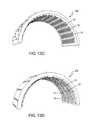
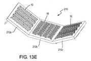
- FIGS. 13A-Eshow examples heating element installations.
- FIG. 13Ashows an exemplary cylindrical installation 200 with staggered heating elements 10 arranged in a circumferential direction, i.e., the axis of the heating element is not parallel to the axis of the cylinder.
- the staggered heating elements 10are more clearly seen where the ends of the heating elements are visible, such as at location 202 .
- Staggeringcontributes to minimizing non-uniformity caused by the void in emitter surface at the terminal end of the heating element by distributing this terminal end position within the assembly across the heating surface.
- the size of the staggercan be smaller or greater, depending on the application and the desired result.
- FIG. 13Bshows another exemplary cylindrical installation 204 with non-staggered hearing elements 10 arranged in a circumferential direction, i.e., the axis of the heating element is not parallel to the axis of the cylinder.
- FIG. 13Cshows an exemplary semi-cylindrical installation 206 with heating elements 10 arranged axially, i.e., the axis of the heating element is parallel to the axis of the cylinder.
- FIG. 13Dshows an exemplary semi-cylindrical installation 208 with heating elements 10 arranged in a circumferential direction, i.e., the axis of the heating element is not parallel to the axis of the cylinder.
- FIG. 13Eshows an exemplary planar-angled installation 210 with heating elements 10 on adjoining planar sections 212 a , 212 b , 212 c being oriented in different directions.
- the axes of the heating elements 10 in a first planar section 212 acan be non-parallel, alternatively perpendicular, to the axes of the heating elements 10 in a second planar section 212 b .
- the planar-angled installation 210one can, for example, be used to approximate cylinder and semi-cylinders installations. These installations are merely illustrative and any installation arrangement can be used that obtains the desired heating and temperature profile.
- the radii of the radiused segmentsare sized to maximize temperature uniformity and minimize stress.
- the inside radiihave a particular low stress when compared to the conventional designs consisting primarily of curved sections. Further, the uniformity of surface temperatures is much improved relative to conventional designs consisting of square patterns with little or no radii at the corners.
- the heating elements disclosed hereinhave a high surface loading factor, also known as a fill factor.
- the pseudo-square and pseudo-sinusoidal heating elementshave more emitter surface area than conventional designs consisting primarily of curved sections. This is, at least in part, because the angular sum of a single cycle is greater than 360 degrees. This puts the first straight segments in non-parallel relationship with a resulting longer length than parallel segments, and therefore, more emitting surface.
- the distance D 2is minimized while the distance D 1 is varied to accommodate the length (L 2 ) of the first straight segment 22 . This contributes to a high fill factor while increasing temperature uniformity and lowering stress in the lobes 38 .
- An example of a typical surface loading of total active areais approximately 145% of the emitter loading.
- the heating elements disclosed hereincontribute to controlling thermal expansion effects. Materials forming the heating element expand upon heating proportional to the coefficient of thermal expansion of the material. This expansion can cause the heating element to flex and bend, resulting in the emitter surface having a variable position relative to a piece to be heated (and, therefore, making the temperature profile more non-uniform). In extreme situations, the flexing and bending can result in short circuiting.
- the heating elements disclosed hereincontrol and minimize the effects the thermal expansion.
- the non-parallel orientation of the first straight segmentsdirect a portion of the thermal expansion in the lateral direction into the longitudinal direction, and therefore maintains the orientation relative to the piece to be heated and a more uniform temperature profile.
- the edges of the patterncan be curved or bent along the lateral axis in order to direct the thermal expansion toward the insulating substrate to permit placement of the heating element closer to adjacent objects, such as additional circuits, with reduced instance of short circuiting.
- mounting meanswith a stand-off distance can also contribute to improved performance.
- Alternating support locations along the length of the circuitous pathallows thermal expansion of the heating element to be directed into a twisting or torsional movement of the heating element between the supports and not just in planar movement.
- the heating elements disclosed hereinare free-radiating. That is, the mounting members provide a stand-off distance for the heating element relative to the insulating substrate.
- the architectureallows for heat to emit from all sides evenly and without the use of extra electrical energy to compensate for, for example, heating a substrate in surface contact to the heating element.
- the free-radiating heating elementlowers the operating temperature of the emitter.
- such a heating elementwill have a longer life at the same substrate power density as conventional heating elements or, alternatively, can operate at higher power densities over comparably life times.
- the disclosed embodimentsresult in a high performance heating element combining low mass and high surface area.
- the disclosed patternsenable a high degree of automation in the fabrication and assembly process and precise geometries yielding uniform heating and consistent performance.
- the heating elementcan have different thicknesses, varying, for example, from about 0.5 mm to about 10 mm.
- the heating elementcan have different widths, based on the width of the straight segments, varying, for example, from about 5 mm or longer. These variations in width and thickness can be suitably incorporated as long as the basic features of the geometry are maintained, i.e., the non-parallel first straight segments and a substantially straight overall pattern.
Landscapes
- Engineering & Computer Science (AREA)
- Physics & Mathematics (AREA)
- Condensed Matter Physics & Semiconductors (AREA)
- General Physics & Mathematics (AREA)
- Manufacturing & Machinery (AREA)
- Computer Hardware Design (AREA)
- Microelectronics & Electronic Packaging (AREA)
- Power Engineering (AREA)
- Resistance Heating (AREA)
- Surface Heating Bodies (AREA)
- Furnace Details (AREA)
Abstract
Description
β=Σαn
where n=number of radiused segments in the lobe. As each cycle includes two lobes, an angular sum of the angles α associated with a single cycle of the circuitous path is greater than 360 degrees, preferably greater than 360 degrees to about 400 degrees, more preferably about 370 to about 380 degrees.
where L1.Ais the length L1of a first first
Claims (33)
Priority Applications (1)
| Application Number | Priority Date | Filing Date | Title |
|---|---|---|---|
| US12/697,719US8395096B2 (en) | 2009-02-05 | 2010-02-01 | Precision strip heating element |
Applications Claiming Priority (2)
| Application Number | Priority Date | Filing Date | Title |
|---|---|---|---|
| US20220609P | 2009-02-05 | 2009-02-05 | |
| US12/697,719US8395096B2 (en) | 2009-02-05 | 2010-02-01 | Precision strip heating element |
Publications (2)
| Publication Number | Publication Date |
|---|---|
| US20100193505A1 US20100193505A1 (en) | 2010-08-05 |
| US8395096B2true US8395096B2 (en) | 2013-03-12 |
Family
ID=42124610
Family Applications (1)
| Application Number | Title | Priority Date | Filing Date |
|---|---|---|---|
| US12/697,719Expired - Fee RelatedUS8395096B2 (en) | 2009-02-05 | 2010-02-01 | Precision strip heating element |
Country Status (6)
| Country | Link |
|---|---|
| US (1) | US8395096B2 (en) |
| EP (1) | EP2217035A1 (en) |
| JP (1) | JP2010238658A (en) |
| KR (1) | KR101707682B1 (en) |
| CN (1) | CN101801124B (en) |
| TW (1) | TW201038107A (en) |
Families Citing this family (17)
| Publication number | Priority date | Publication date | Assignee | Title |
|---|---|---|---|---|
| DE102006034077A1 (en)* | 2005-08-16 | 2007-02-22 | Robert Bosch Gmbh | Filter device with a heater |
| DE102007005771B4 (en)* | 2007-02-06 | 2017-07-06 | Robert Bosch Gmbh | Filter device, in particular liquid filter, with a heater |
| KR101338350B1 (en) | 2007-07-16 | 2013-12-31 | 삼성전자주식회사 | Method for forming nanostructure or poly silicone using microheater, nanostructure or poly silicone formed by the method and electronic device using the same |
| KR101318292B1 (en)* | 2007-11-30 | 2013-10-18 | 삼성전자주식회사 | Microheater, microheater array, method for manufacturing the same and electronic device using the same |
| KR20090122083A (en)* | 2008-05-23 | 2009-11-26 | 삼성전자주식회사 | Micro heater, micro heater array, method of manufacturing the same and electronic device using the same |
| KR20090128006A (en)* | 2008-06-10 | 2009-12-15 | 삼성전자주식회사 | Micro heater, micro heater array, manufacturing method thereof and pattern forming method using the same |
| JP5544121B2 (en)* | 2009-07-21 | 2014-07-09 | 株式会社日立国際電気 | Heating apparatus, substrate processing apparatus, and semiconductor device manufacturing method |
| US9064912B2 (en)* | 2009-07-21 | 2015-06-23 | Hitachi Kokusai Electric, Inc. | Heating device, substrate processing apparatus, and method of manufacturing semiconductor device |
| US10880954B2 (en)* | 2010-11-05 | 2020-12-29 | Tutco, Llc | Foldable electric resistance heater and method of use |
| GB2500733B (en)* | 2012-06-25 | 2014-05-21 | Jemella Ltd | Hair styling appliance |
| KR101373634B1 (en)* | 2012-11-05 | 2014-03-13 | 윤태영 | Ceramic heater possible windingness |
| JPWO2014073545A1 (en)* | 2012-11-06 | 2016-09-08 | 貞徳舎株式会社 | Electric heater, heating apparatus and semiconductor manufacturing apparatus provided with the same |
| US9730276B2 (en)* | 2013-11-19 | 2017-08-08 | Mhi Health Devices, Llc | Flat heating element comprising twists and bends and method thereby to relieve heating element stress |
| KR20160090324A (en)* | 2013-11-26 | 2016-07-29 | 코닝 인코포레이티드 | Glass manufacturing apparatus and methods of fabricating glass ribbon |
| JP5777764B2 (en)* | 2014-04-03 | 2015-09-09 | キヤノン株式会社 | Heater and image heating apparatus equipped with the heater |
| CN104470002B (en)* | 2014-11-15 | 2016-08-17 | 北京星航机电装备有限公司 | A kind of ceramic heating device |
| DE102016118137A1 (en)* | 2016-09-26 | 2018-03-29 | Heraeus Noblelight Gmbh | Infrared Panel Heaters |
Citations (41)
| Publication number | Priority date | Publication date | Assignee | Title |
|---|---|---|---|---|
| US3757083A (en) | 1972-02-22 | 1973-09-04 | Armstrong Cork Co | Connector for high output quick response radiant heater |
| US4100395A (en) | 1976-06-29 | 1978-07-11 | Glenro, Inc. | Expanded element radiant heating device |
| US4243874A (en) | 1977-07-02 | 1981-01-06 | Karl Fischer | Radiant heating unit |
| GB1604282A (en) | 1977-06-23 | 1981-12-09 | Rhone Poulenc Ind | Elements which heat by convection and radiation |
| US4386749A (en) | 1977-03-04 | 1983-06-07 | The B. F. Goodrich Company | Propeller deicer |
| US4596922A (en) | 1984-01-24 | 1986-06-24 | Thermtec | Heating element |
| GB2196819A (en) | 1986-10-24 | 1988-05-05 | Rotfil Srl | A heater band for machines for working plastics materials |
| JPH02103885A (en) | 1988-10-11 | 1990-04-16 | Hanawa Netsuden Kinzoku Kk | Heat generating device |
| EP0396030A2 (en) | 1989-05-05 | 1990-11-07 | Karl Hehl | Heating apparatus for a machine for working plastic materials |
| JPH0362491A (en) | 1989-07-31 | 1991-03-18 | Hanawa Netsuden Kinzoku Kk | Heat generating device |
| JPH0363494A (en) | 1989-07-31 | 1991-03-19 | Hanawa Netsuden Kinzoku Kk | High temperature heating device |
| JPH0363495A (en) | 1989-07-31 | 1991-03-19 | Hanawa Netsuden Kinzoku Kk | High temperature heating device |
| JPH03138886A (en) | 1989-10-24 | 1991-06-13 | Hanawa Netsuden Kinzoku Kk | Manufacture of carbon fiber/carbon composite heating element |
| US5038019A (en) | 1990-02-06 | 1991-08-06 | Thermtec, Inc. | High temperature diffusion furnace |
| JPH0557793A (en)* | 1991-08-30 | 1993-03-09 | Toshiba Lighting & Technol Corp | Ultraviolet irradiation device and method for applying ultraviolet curable resin in piping |
| US5323484A (en) | 1992-02-03 | 1994-06-21 | Tokyo Electron Sagami Kabushiki Kaisha | Heating apparatus with multilayer insulating structure |
| US5461214A (en) | 1992-06-15 | 1995-10-24 | Thermtec, Inc. | High performance horizontal diffusion furnace system |
| JPH10273782A (en) | 1997-03-31 | 1998-10-13 | Nippon Sanso Kk | Substrate heating device in CVD equipment |
| JPH1114269A (en) | 1997-06-19 | 1999-01-22 | Mitsubishi Materials Shilicon Corp | Heater electrode structure |
| US6160957A (en) | 1997-01-29 | 2000-12-12 | Kanthal Ab | Infrared radiation panel |
| JP3138886B2 (en) | 1992-02-14 | 2001-02-26 | 株式会社シード | Method for producing transparent lead-containing polymer |
| US6225602B1 (en) | 1997-05-02 | 2001-05-01 | Advanced Semiconductor Materials International N.V. | Vertical furnace for the treatment of semiconductor substrates |
| JP2001167862A (en) | 1999-12-10 | 2001-06-22 | Murata Mfg Co Ltd | Heater and structure of heater terminal |
| JP2002203662A (en) | 2000-10-31 | 2002-07-19 | Sumitomo Osaka Cement Co Ltd | Heater element, heating device, and base board heating device |
| JP2002270529A (en) | 2001-03-06 | 2002-09-20 | Hitachi Kokusai Electric Inc | Substrate processing equipment |
| US6471780B1 (en) | 1998-03-13 | 2002-10-29 | Micron Technology, Inc. | Process for fabricating films of uniform properties on semiconductor devices |
| JP2002372381A (en) | 2001-06-13 | 2002-12-26 | Sakaguchi Dennetsu Kk | Heating furnace and method for producing heater thereof |
| JP2004039967A (en) | 2002-07-05 | 2004-02-05 | Hitachi Kokusai Electric Inc | Semiconductor manufacturing equipment |
| JP2004111332A (en) | 2002-09-20 | 2004-04-08 | Tokyo Kogyo Boyeki Shokai Ltd | Expansion heating wire |
| JP2004132587A (en) | 2002-10-09 | 2004-04-30 | National Institute Of Advanced Industrial & Technology | heating furnace |
| US6807220B1 (en) | 2003-05-23 | 2004-10-19 | Mrl Industries | Retention mechanism for heating coil of high temperature diffusion furnace |
| JP2005129273A (en) | 2003-10-21 | 2005-05-19 | Teitokusha Kk | Electric heater |
| JP2005150101A (en) | 2003-10-21 | 2005-06-09 | Teitokusha Kk | Electric heater and furnace equipped with the same |
| JP2005302593A (en) | 2004-04-14 | 2005-10-27 | Nikko Materials Co Ltd | Ceramic platy heating element |
| US7027722B2 (en) | 2002-11-25 | 2006-04-11 | Koyo Thermo Systems Co., Ltd. | Electric heater for a semiconductor processing apparatus |
| JP2006100755A (en) | 2003-10-21 | 2006-04-13 | Hitachi Kokusai Electric Inc | Substrate processing apparatus, electric heater for substrate processing apparatus, and substrate processing apparatus provided with the same |
| JP2006156119A (en) | 2004-11-29 | 2006-06-15 | Bridgestone Corp | Heater unit |
| US20070039938A1 (en) | 2005-08-19 | 2007-02-22 | Peck Kevin B | Fault tolerant element and combination with fault tolerant circuit |
| JP2007088324A (en) | 2005-09-26 | 2007-04-05 | Hitachi Kokusai Electric Inc | Heating element holding structure, insulating structure, heating apparatus, and substrate processing apparatus |
| US20070257022A1 (en)* | 2006-05-03 | 2007-11-08 | Watlow Electric Manufacturing Company | Power terminals for ceramic heater and method of making the same |
| WO2008089951A1 (en) | 2007-01-24 | 2008-07-31 | Valeo Klimasysteme Gmbh | Airflow heating device with heating nonwoven fabric |
Family Cites Families (6)
| Publication number | Priority date | Publication date | Assignee | Title |
|---|---|---|---|---|
| GB767954A (en)* | 1953-09-23 | 1957-02-13 | Richardson & Sheeres Ltd | Improvements in the construction of electrically heated textiles |
| GB911744A (en)* | 1959-10-27 | 1962-11-28 | Gordon Augustus Middleton | Improvements in electric-heating panels |
| JPS52142344A (en)* | 1976-05-24 | 1977-11-28 | Mitsui Toatsu Chem Inc | Long band-like heater |
| JP3568261B2 (en)* | 1994-12-26 | 2004-09-22 | 三井化学株式会社 | Planar heating element |
| WO2003078910A1 (en)* | 2002-03-19 | 2003-09-25 | Koyo Thermo Systems Co., Ltd. | Electric heater for thermal treatment furnace |
| DE102009010666A1 (en)* | 2009-02-27 | 2010-09-02 | Fraunhofer-Gesellschaft zur Förderung der angewandten Forschung e.V. | Electric heating |
- 2010
- 2010-02-01USUS12/697,719patent/US8395096B2/ennot_activeExpired - Fee Related
- 2010-02-04EPEP10152692Apatent/EP2217035A1/ennot_activeWithdrawn
- 2010-02-05JPJP2010024452Apatent/JP2010238658A/ennot_activeWithdrawn
- 2010-02-05TWTW099103553Apatent/TW201038107A/enunknown
- 2010-02-05CNCN201010113670.6Apatent/CN101801124B/enactiveActive
- 2010-02-05KRKR1020100010921Apatent/KR101707682B1/enactiveActive
Patent Citations (45)
| Publication number | Priority date | Publication date | Assignee | Title |
|---|---|---|---|---|
| US3757083A (en) | 1972-02-22 | 1973-09-04 | Armstrong Cork Co | Connector for high output quick response radiant heater |
| US4100395A (en) | 1976-06-29 | 1978-07-11 | Glenro, Inc. | Expanded element radiant heating device |
| US4386749A (en) | 1977-03-04 | 1983-06-07 | The B. F. Goodrich Company | Propeller deicer |
| US4386749B1 (en) | 1977-03-04 | 1995-09-12 | Goodrich Co B F | Propeller deicer |
| GB1604282A (en) | 1977-06-23 | 1981-12-09 | Rhone Poulenc Ind | Elements which heat by convection and radiation |
| US4243874A (en) | 1977-07-02 | 1981-01-06 | Karl Fischer | Radiant heating unit |
| US4596922A (en) | 1984-01-24 | 1986-06-24 | Thermtec | Heating element |
| GB2196819A (en) | 1986-10-24 | 1988-05-05 | Rotfil Srl | A heater band for machines for working plastics materials |
| JPH02103885A (en) | 1988-10-11 | 1990-04-16 | Hanawa Netsuden Kinzoku Kk | Heat generating device |
| US5157241A (en) | 1989-05-05 | 1992-10-20 | Karl Hehl | Temperature control device provided in a plastic-processing machine |
| EP0396030A2 (en) | 1989-05-05 | 1990-11-07 | Karl Hehl | Heating apparatus for a machine for working plastic materials |
| JPH0363494A (en) | 1989-07-31 | 1991-03-19 | Hanawa Netsuden Kinzoku Kk | High temperature heating device |
| JPH0363495A (en) | 1989-07-31 | 1991-03-19 | Hanawa Netsuden Kinzoku Kk | High temperature heating device |
| JPH0362491A (en) | 1989-07-31 | 1991-03-18 | Hanawa Netsuden Kinzoku Kk | Heat generating device |
| JPH03138886A (en) | 1989-10-24 | 1991-06-13 | Hanawa Netsuden Kinzoku Kk | Manufacture of carbon fiber/carbon composite heating element |
| US5038019A (en) | 1990-02-06 | 1991-08-06 | Thermtec, Inc. | High temperature diffusion furnace |
| US5095192A (en) | 1990-02-06 | 1992-03-10 | Thermtec, Inc. | High temperature diffusion furnace |
| JPH0557793A (en)* | 1991-08-30 | 1993-03-09 | Toshiba Lighting & Technol Corp | Ultraviolet irradiation device and method for applying ultraviolet curable resin in piping |
| US5323484A (en) | 1992-02-03 | 1994-06-21 | Tokyo Electron Sagami Kabushiki Kaisha | Heating apparatus with multilayer insulating structure |
| JP3138886B2 (en) | 1992-02-14 | 2001-02-26 | 株式会社シード | Method for producing transparent lead-containing polymer |
| US5461214A (en) | 1992-06-15 | 1995-10-24 | Thermtec, Inc. | High performance horizontal diffusion furnace system |
| US6160957A (en) | 1997-01-29 | 2000-12-12 | Kanthal Ab | Infrared radiation panel |
| JPH10273782A (en) | 1997-03-31 | 1998-10-13 | Nippon Sanso Kk | Substrate heating device in CVD equipment |
| US6225602B1 (en) | 1997-05-02 | 2001-05-01 | Advanced Semiconductor Materials International N.V. | Vertical furnace for the treatment of semiconductor substrates |
| JPH1114269A (en) | 1997-06-19 | 1999-01-22 | Mitsubishi Materials Shilicon Corp | Heater electrode structure |
| US6471780B1 (en) | 1998-03-13 | 2002-10-29 | Micron Technology, Inc. | Process for fabricating films of uniform properties on semiconductor devices |
| JP2001167862A (en) | 1999-12-10 | 2001-06-22 | Murata Mfg Co Ltd | Heater and structure of heater terminal |
| JP2002203662A (en) | 2000-10-31 | 2002-07-19 | Sumitomo Osaka Cement Co Ltd | Heater element, heating device, and base board heating device |
| JP2002270529A (en) | 2001-03-06 | 2002-09-20 | Hitachi Kokusai Electric Inc | Substrate processing equipment |
| JP2002372381A (en) | 2001-06-13 | 2002-12-26 | Sakaguchi Dennetsu Kk | Heating furnace and method for producing heater thereof |
| JP2004039967A (en) | 2002-07-05 | 2004-02-05 | Hitachi Kokusai Electric Inc | Semiconductor manufacturing equipment |
| JP2004111332A (en) | 2002-09-20 | 2004-04-08 | Tokyo Kogyo Boyeki Shokai Ltd | Expansion heating wire |
| JP2004132587A (en) | 2002-10-09 | 2004-04-30 | National Institute Of Advanced Industrial & Technology | heating furnace |
| US7027722B2 (en) | 2002-11-25 | 2006-04-11 | Koyo Thermo Systems Co., Ltd. | Electric heater for a semiconductor processing apparatus |
| US6807220B1 (en) | 2003-05-23 | 2004-10-19 | Mrl Industries | Retention mechanism for heating coil of high temperature diffusion furnace |
| JP2005129273A (en) | 2003-10-21 | 2005-05-19 | Teitokusha Kk | Electric heater |
| JP2005150101A (en) | 2003-10-21 | 2005-06-09 | Teitokusha Kk | Electric heater and furnace equipped with the same |
| JP2006100755A (en) | 2003-10-21 | 2006-04-13 | Hitachi Kokusai Electric Inc | Substrate processing apparatus, electric heater for substrate processing apparatus, and substrate processing apparatus provided with the same |
| JP2005302593A (en) | 2004-04-14 | 2005-10-27 | Nikko Materials Co Ltd | Ceramic platy heating element |
| JP2006156119A (en) | 2004-11-29 | 2006-06-15 | Bridgestone Corp | Heater unit |
| US20070039938A1 (en) | 2005-08-19 | 2007-02-22 | Peck Kevin B | Fault tolerant element and combination with fault tolerant circuit |
| JP2007088324A (en) | 2005-09-26 | 2007-04-05 | Hitachi Kokusai Electric Inc | Heating element holding structure, insulating structure, heating apparatus, and substrate processing apparatus |
| US20070257022A1 (en)* | 2006-05-03 | 2007-11-08 | Watlow Electric Manufacturing Company | Power terminals for ceramic heater and method of making the same |
| WO2008089951A1 (en) | 2007-01-24 | 2008-07-31 | Valeo Klimasysteme Gmbh | Airflow heating device with heating nonwoven fabric |
| DE102007003549A1 (en) | 2007-01-24 | 2008-07-31 | Valeo Klimasysteme Gmbh | Air flow heating device with heating fleece |
Also Published As
| Publication number | Publication date |
|---|---|
| EP2217035A1 (en) | 2010-08-11 |
| CN101801124A (en) | 2010-08-11 |
| JP2010238658A (en) | 2010-10-21 |
| US20100193505A1 (en) | 2010-08-05 |
| KR101707682B1 (en) | 2017-02-16 |
| KR20100090220A (en) | 2010-08-13 |
| TW201038107A (en) | 2010-10-16 |
| CN101801124B (en) | 2014-07-30 |
Similar Documents
| Publication | Publication Date | Title |
|---|---|---|
| US8395096B2 (en) | Precision strip heating element | |
| TW575934B (en) | A heating apparatus | |
| EP1351281B1 (en) | Ceramic heaters | |
| KR100281954B1 (en) | Ceramic heater | |
| US20030183616A1 (en) | Ceramic heater | |
| US8193473B2 (en) | Uniform temperature heater | |
| US20080237216A1 (en) | Heating device | |
| US8785825B2 (en) | Support structure for heating element coil | |
| KR20160090383A (en) | Heating device | |
| EP3168467B1 (en) | Self-regulating thermal insulation and related methods | |
| US20050173413A1 (en) | Heaters | |
| US9144114B2 (en) | Heater element as well as an insert for electrical furnaces | |
| WO2014157369A1 (en) | Metal heating element and heat-generating structure | |
| US8164028B2 (en) | Resistance heater | |
| RU2344575C2 (en) | Silicon-carbid heating elements | |
| JP2013097943A (en) | Heater and method of manufacturing the same | |
| KR101394325B1 (en) | Heater and method for manufacturing the same | |
| JP2023516170A (en) | heating device | |
| WO2002091800A1 (en) | Mosi2 arc-shaped heater, and method and device for manufacturing the heater | |
| CN110418576B (en) | Improved power transfer system for wire mesh heaters | |
| US7446286B2 (en) | Heater strip for an electric heater, heater with such a heater strip and method for manufacturing the heater strip | |
| CN1812671A (en) | Radiant electric heating element | |
| US20140238975A1 (en) | Monolithic thermal heating block made from refractory phosphate cement | |
| JP3527978B2 (en) | heating furnace | |
| JP6378244B2 (en) | Exothermic structure |
Legal Events
| Date | Code | Title | Description |
|---|---|---|---|
| AS | Assignment | Owner name:MRL INDUSTRIES, INC., CALIFORNIA Free format text:ASSIGNMENT OF ASSIGNORS INTEREST;ASSIGNOR:PECK, KEVIN B.;REEL/FRAME:024078/0843 Effective date:20100301 | |
| AS | Assignment | Owner name:SANDVIK THERMAL PROCESS, INC., CALIFORNIA Free format text:CHANGE OF NAME;ASSIGNOR:MRL INDUSTRIES, INC.;REEL/FRAME:029801/0102 Effective date:20100518 | |
| STCF | Information on status: patent grant | Free format text:PATENTED CASE | |
| FPAY | Fee payment | Year of fee payment:4 | |
| MAFP | Maintenance fee payment | Free format text:PAYMENT OF MAINTENANCE FEE, 8TH YEAR, LARGE ENTITY (ORIGINAL EVENT CODE: M1552); ENTITY STATUS OF PATENT OWNER: LARGE ENTITY Year of fee payment:8 | |
| AS | Assignment | Owner name:KANTHAL THERMAL PROCESS, INC., CALIFORNIA Free format text:CHANGE OF NAME;ASSIGNOR:SANDVIK THERMAL PROCESS, INC.;REEL/FRAME:057523/0733 Effective date:20201215 | |
| FEPP | Fee payment procedure | Free format text:MAINTENANCE FEE REMINDER MAILED (ORIGINAL EVENT CODE: REM.); ENTITY STATUS OF PATENT OWNER: LARGE ENTITY | |
| LAPS | Lapse for failure to pay maintenance fees | Free format text:PATENT EXPIRED FOR FAILURE TO PAY MAINTENANCE FEES (ORIGINAL EVENT CODE: EXP.); ENTITY STATUS OF PATENT OWNER: LARGE ENTITY | |
| STCH | Information on status: patent discontinuation | Free format text:PATENT EXPIRED DUE TO NONPAYMENT OF MAINTENANCE FEES UNDER 37 CFR 1.362 | |
| FP | Lapsed due to failure to pay maintenance fee | Effective date:20250312 |