US8394142B2 - Customizing an intervertebral implant - Google Patents
Customizing an intervertebral implantDownload PDFInfo
- Publication number
- US8394142B2 US8394142B2US11/150,468US15046805AUS8394142B2US 8394142 B2US8394142 B2US 8394142B2US 15046805 AUS15046805 AUS 15046805AUS 8394142 B2US8394142 B2US 8394142B2
- Authority
- US
- United States
- Prior art keywords
- abnormal
- vertebra
- vertebrae
- intervertebral implant
- implant
- Prior art date
- Legal status (The legal status is an assumption and is not a legal conclusion. Google has not performed a legal analysis and makes no representation as to the accuracy of the status listed.)
- Active, expires
Links
- 239000007943implantSubstances0.000titleclaimsabstractdescription144
- 230000002159abnormal effectEffects0.000claimsabstractdescription121
- 238000000034methodMethods0.000claimsabstractdescription35
- 210000003484anatomyAnatomy0.000claimsabstractdescription21
- 238000003801millingMethods0.000claimsdescription7
- 238000002513implantationMethods0.000claimsdescription6
- 230000001788irregularEffects0.000claimsdescription6
- 238000009499grossingMethods0.000claimsdescription5
- 238000003780insertionMethods0.000claimsdescription5
- 230000037431insertionEffects0.000claimsdescription5
- FGUUSXIOTUKUDN-IBGZPJMESA-NC1(=CC=CC=C1)N1C2=C(NC([C@H](C1)NC=1OC(=NN=1)C1=CC=CC=C1)=O)C=CC=C2Chemical compoundC1(=CC=CC=C1)N1C2=C(NC([C@H](C1)NC=1OC(=NN=1)C1=CC=CC=C1)=O)C=CC=C2FGUUSXIOTUKUDN-IBGZPJMESA-N0.000claims4
- 230000004927fusionEffects0.000description5
- 208000014674injuryDiseases0.000description5
- 206010039722scoliosisDiseases0.000description5
- 230000008733traumaEffects0.000description5
- 238000002591computed tomographyMethods0.000description3
- 230000036244malformationEffects0.000description3
- 230000008901benefitEffects0.000description2
- 230000006872improvementEffects0.000description2
- 238000007493shaping processMethods0.000description2
- 238000001356surgical procedureMethods0.000description2
- 208000008035Back PainDiseases0.000description1
- 206010061246Intervertebral disc degenerationDiseases0.000description1
- 206010023509KyphosisDiseases0.000description1
- 239000004698PolyethyleneSubstances0.000description1
- 206010041541Spinal compression fractureDiseases0.000description1
- 230000005856abnormalityEffects0.000description1
- 230000003466anti-cipated effectEffects0.000description1
- 238000010276constructionMethods0.000description1
- 208000018180degenerative disc diseaseDiseases0.000description1
- 230000001419dependent effectEffects0.000description1
- 201000010099diseaseDiseases0.000description1
- 208000037265diseases, disorders, signs and symptomsDiseases0.000description1
- 208000021600intervertebral disc degenerative diseaseDiseases0.000description1
- 238000004519manufacturing processMethods0.000description1
- 230000013011matingEffects0.000description1
- 238000012986modificationMethods0.000description1
- 230000004048modificationEffects0.000description1
- 230000007935neutral effectEffects0.000description1
- -1polyethylenePolymers0.000description1
- 229920000573polyethylenePolymers0.000description1
- 230000008439repair processEffects0.000description1
- 230000000717retained effectEffects0.000description1
- 208000029761vertebral diseaseDiseases0.000description1
Images


Classifications
- A—HUMAN NECESSITIES
- A61—MEDICAL OR VETERINARY SCIENCE; HYGIENE
- A61F—FILTERS IMPLANTABLE INTO BLOOD VESSELS; PROSTHESES; DEVICES PROVIDING PATENCY TO, OR PREVENTING COLLAPSING OF, TUBULAR STRUCTURES OF THE BODY, e.g. STENTS; ORTHOPAEDIC, NURSING OR CONTRACEPTIVE DEVICES; FOMENTATION; TREATMENT OR PROTECTION OF EYES OR EARS; BANDAGES, DRESSINGS OR ABSORBENT PADS; FIRST-AID KITS
- A61F2/00—Filters implantable into blood vessels; Prostheses, i.e. artificial substitutes or replacements for parts of the body; Appliances for connecting them with the body; Devices providing patency to, or preventing collapsing of, tubular structures of the body, e.g. stents
- A61F2/02—Prostheses implantable into the body
- A61F2/30—Joints
- A61F2/44—Joints for the spine, e.g. vertebrae, spinal discs
- A—HUMAN NECESSITIES
- A61—MEDICAL OR VETERINARY SCIENCE; HYGIENE
- A61F—FILTERS IMPLANTABLE INTO BLOOD VESSELS; PROSTHESES; DEVICES PROVIDING PATENCY TO, OR PREVENTING COLLAPSING OF, TUBULAR STRUCTURES OF THE BODY, e.g. STENTS; ORTHOPAEDIC, NURSING OR CONTRACEPTIVE DEVICES; FOMENTATION; TREATMENT OR PROTECTION OF EYES OR EARS; BANDAGES, DRESSINGS OR ABSORBENT PADS; FIRST-AID KITS
- A61F2/00—Filters implantable into blood vessels; Prostheses, i.e. artificial substitutes or replacements for parts of the body; Appliances for connecting them with the body; Devices providing patency to, or preventing collapsing of, tubular structures of the body, e.g. stents
- A61F2/02—Prostheses implantable into the body
- A61F2/30—Joints
- A61F2/3094—Designing or manufacturing processes
- A61F2/30942—Designing or manufacturing processes for designing or making customized prostheses, e.g. using templates, CT or NMR scans, finite-element analysis or CAD-CAM techniques
- A—HUMAN NECESSITIES
- A61—MEDICAL OR VETERINARY SCIENCE; HYGIENE
- A61F—FILTERS IMPLANTABLE INTO BLOOD VESSELS; PROSTHESES; DEVICES PROVIDING PATENCY TO, OR PREVENTING COLLAPSING OF, TUBULAR STRUCTURES OF THE BODY, e.g. STENTS; ORTHOPAEDIC, NURSING OR CONTRACEPTIVE DEVICES; FOMENTATION; TREATMENT OR PROTECTION OF EYES OR EARS; BANDAGES, DRESSINGS OR ABSORBENT PADS; FIRST-AID KITS
- A61F2/00—Filters implantable into blood vessels; Prostheses, i.e. artificial substitutes or replacements for parts of the body; Appliances for connecting them with the body; Devices providing patency to, or preventing collapsing of, tubular structures of the body, e.g. stents
- A61F2/02—Prostheses implantable into the body
- A61F2/30—Joints
- A61F2/46—Special tools for implanting artificial joints
- A61F2/4684—Trial or dummy prostheses
- A—HUMAN NECESSITIES
- A61—MEDICAL OR VETERINARY SCIENCE; HYGIENE
- A61B—DIAGNOSIS; SURGERY; IDENTIFICATION
- A61B5/00—Measuring for diagnostic purposes; Identification of persons
- A61B5/103—Measuring devices for testing the shape, pattern, colour, size or movement of the body or parts thereof, for diagnostic purposes
- A61B5/107—Measuring physical dimensions, e.g. size of the entire body or parts thereof
- A61B5/1075—Measuring physical dimensions, e.g. size of the entire body or parts thereof for measuring dimensions by non-invasive methods, e.g. for determining thickness of tissue layer
- A—HUMAN NECESSITIES
- A61—MEDICAL OR VETERINARY SCIENCE; HYGIENE
- A61F—FILTERS IMPLANTABLE INTO BLOOD VESSELS; PROSTHESES; DEVICES PROVIDING PATENCY TO, OR PREVENTING COLLAPSING OF, TUBULAR STRUCTURES OF THE BODY, e.g. STENTS; ORTHOPAEDIC, NURSING OR CONTRACEPTIVE DEVICES; FOMENTATION; TREATMENT OR PROTECTION OF EYES OR EARS; BANDAGES, DRESSINGS OR ABSORBENT PADS; FIRST-AID KITS
- A61F2/00—Filters implantable into blood vessels; Prostheses, i.e. artificial substitutes or replacements for parts of the body; Appliances for connecting them with the body; Devices providing patency to, or preventing collapsing of, tubular structures of the body, e.g. stents
- A61F2/02—Prostheses implantable into the body
- A61F2/30—Joints
- A61F2/44—Joints for the spine, e.g. vertebrae, spinal discs
- A61F2/442—Intervertebral or spinal discs, e.g. resilient
- A61F2/4425—Intervertebral or spinal discs, e.g. resilient made of articulated components
- A—HUMAN NECESSITIES
- A61—MEDICAL OR VETERINARY SCIENCE; HYGIENE
- A61F—FILTERS IMPLANTABLE INTO BLOOD VESSELS; PROSTHESES; DEVICES PROVIDING PATENCY TO, OR PREVENTING COLLAPSING OF, TUBULAR STRUCTURES OF THE BODY, e.g. STENTS; ORTHOPAEDIC, NURSING OR CONTRACEPTIVE DEVICES; FOMENTATION; TREATMENT OR PROTECTION OF EYES OR EARS; BANDAGES, DRESSINGS OR ABSORBENT PADS; FIRST-AID KITS
- A61F2/00—Filters implantable into blood vessels; Prostheses, i.e. artificial substitutes or replacements for parts of the body; Appliances for connecting them with the body; Devices providing patency to, or preventing collapsing of, tubular structures of the body, e.g. stents
- A61F2/02—Prostheses implantable into the body
- A61F2/30—Joints
- A61F2/46—Special tools for implanting artificial joints
- A61F2/4603—Special tools for implanting artificial joints for insertion or extraction of endoprosthetic joints or of accessories thereof
- A61F2/4611—Special tools for implanting artificial joints for insertion or extraction of endoprosthetic joints or of accessories thereof of spinal prostheses
- A—HUMAN NECESSITIES
- A61—MEDICAL OR VETERINARY SCIENCE; HYGIENE
- A61F—FILTERS IMPLANTABLE INTO BLOOD VESSELS; PROSTHESES; DEVICES PROVIDING PATENCY TO, OR PREVENTING COLLAPSING OF, TUBULAR STRUCTURES OF THE BODY, e.g. STENTS; ORTHOPAEDIC, NURSING OR CONTRACEPTIVE DEVICES; FOMENTATION; TREATMENT OR PROTECTION OF EYES OR EARS; BANDAGES, DRESSINGS OR ABSORBENT PADS; FIRST-AID KITS
- A61F2/00—Filters implantable into blood vessels; Prostheses, i.e. artificial substitutes or replacements for parts of the body; Appliances for connecting them with the body; Devices providing patency to, or preventing collapsing of, tubular structures of the body, e.g. stents
- A61F2/02—Prostheses implantable into the body
- A61F2/30—Joints
- A61F2002/30001—Additional features of subject-matter classified in A61F2/28, A61F2/30 and subgroups thereof
- A61F2002/30316—The prosthesis having different structural features at different locations within the same prosthesis; Connections between prosthetic parts; Special structural features of bone or joint prostheses not otherwise provided for
- A61F2002/30329—Connections or couplings between prosthetic parts, e.g. between modular parts; Connecting elements
- A61F2002/30383—Connections or couplings between prosthetic parts, e.g. between modular parts; Connecting elements made by laterally inserting a protrusion, e.g. a rib into a complementarily-shaped groove
- A61F2002/30387—Dovetail connection
- A—HUMAN NECESSITIES
- A61—MEDICAL OR VETERINARY SCIENCE; HYGIENE
- A61F—FILTERS IMPLANTABLE INTO BLOOD VESSELS; PROSTHESES; DEVICES PROVIDING PATENCY TO, OR PREVENTING COLLAPSING OF, TUBULAR STRUCTURES OF THE BODY, e.g. STENTS; ORTHOPAEDIC, NURSING OR CONTRACEPTIVE DEVICES; FOMENTATION; TREATMENT OR PROTECTION OF EYES OR EARS; BANDAGES, DRESSINGS OR ABSORBENT PADS; FIRST-AID KITS
- A61F2/00—Filters implantable into blood vessels; Prostheses, i.e. artificial substitutes or replacements for parts of the body; Appliances for connecting them with the body; Devices providing patency to, or preventing collapsing of, tubular structures of the body, e.g. stents
- A61F2/02—Prostheses implantable into the body
- A61F2/30—Joints
- A61F2/30767—Special external or bone-contacting surface, e.g. coating for improving bone ingrowth
- A61F2/30771—Special external or bone-contacting surface, e.g. coating for improving bone ingrowth applied in original prostheses, e.g. holes or grooves
- A61F2002/30878—Special external or bone-contacting surface, e.g. coating for improving bone ingrowth applied in original prostheses, e.g. holes or grooves with non-sharp protrusions, for instance contacting the bone for anchoring, e.g. keels, pegs, pins, posts, shanks, stems, struts
- A—HUMAN NECESSITIES
- A61—MEDICAL OR VETERINARY SCIENCE; HYGIENE
- A61F—FILTERS IMPLANTABLE INTO BLOOD VESSELS; PROSTHESES; DEVICES PROVIDING PATENCY TO, OR PREVENTING COLLAPSING OF, TUBULAR STRUCTURES OF THE BODY, e.g. STENTS; ORTHOPAEDIC, NURSING OR CONTRACEPTIVE DEVICES; FOMENTATION; TREATMENT OR PROTECTION OF EYES OR EARS; BANDAGES, DRESSINGS OR ABSORBENT PADS; FIRST-AID KITS
- A61F2/00—Filters implantable into blood vessels; Prostheses, i.e. artificial substitutes or replacements for parts of the body; Appliances for connecting them with the body; Devices providing patency to, or preventing collapsing of, tubular structures of the body, e.g. stents
- A61F2/02—Prostheses implantable into the body
- A61F2/30—Joints
- A61F2/3094—Designing or manufacturing processes
- A61F2/30942—Designing or manufacturing processes for designing or making customized prostheses, e.g. using templates, CT or NMR scans, finite-element analysis or CAD-CAM techniques
- A61F2002/30948—Designing or manufacturing processes for designing or making customized prostheses, e.g. using templates, CT or NMR scans, finite-element analysis or CAD-CAM techniques using computerized tomography, i.e. CT scans
- A—HUMAN NECESSITIES
- A61—MEDICAL OR VETERINARY SCIENCE; HYGIENE
- A61F—FILTERS IMPLANTABLE INTO BLOOD VESSELS; PROSTHESES; DEVICES PROVIDING PATENCY TO, OR PREVENTING COLLAPSING OF, TUBULAR STRUCTURES OF THE BODY, e.g. STENTS; ORTHOPAEDIC, NURSING OR CONTRACEPTIVE DEVICES; FOMENTATION; TREATMENT OR PROTECTION OF EYES OR EARS; BANDAGES, DRESSINGS OR ABSORBENT PADS; FIRST-AID KITS
- A61F2/00—Filters implantable into blood vessels; Prostheses, i.e. artificial substitutes or replacements for parts of the body; Appliances for connecting them with the body; Devices providing patency to, or preventing collapsing of, tubular structures of the body, e.g. stents
- A61F2/02—Prostheses implantable into the body
- A61F2/30—Joints
- A61F2/3094—Designing or manufacturing processes
- A61F2/30942—Designing or manufacturing processes for designing or making customized prostheses, e.g. using templates, CT or NMR scans, finite-element analysis or CAD-CAM techniques
- A61F2002/30952—Designing or manufacturing processes for designing or making customized prostheses, e.g. using templates, CT or NMR scans, finite-element analysis or CAD-CAM techniques using CAD-CAM techniques or NC-techniques
- A—HUMAN NECESSITIES
- A61—MEDICAL OR VETERINARY SCIENCE; HYGIENE
- A61F—FILTERS IMPLANTABLE INTO BLOOD VESSELS; PROSTHESES; DEVICES PROVIDING PATENCY TO, OR PREVENTING COLLAPSING OF, TUBULAR STRUCTURES OF THE BODY, e.g. STENTS; ORTHOPAEDIC, NURSING OR CONTRACEPTIVE DEVICES; FOMENTATION; TREATMENT OR PROTECTION OF EYES OR EARS; BANDAGES, DRESSINGS OR ABSORBENT PADS; FIRST-AID KITS
- A61F2/00—Filters implantable into blood vessels; Prostheses, i.e. artificial substitutes or replacements for parts of the body; Appliances for connecting them with the body; Devices providing patency to, or preventing collapsing of, tubular structures of the body, e.g. stents
- A61F2/02—Prostheses implantable into the body
- A61F2/30—Joints
- A61F2/44—Joints for the spine, e.g. vertebrae, spinal discs
- A61F2/442—Intervertebral or spinal discs, e.g. resilient
- A61F2/4425—Intervertebral or spinal discs, e.g. resilient made of articulated components
- A61F2002/443—Intervertebral or spinal discs, e.g. resilient made of articulated components having two transversal endplates and at least one intermediate component
- A—HUMAN NECESSITIES
- A61—MEDICAL OR VETERINARY SCIENCE; HYGIENE
- A61F—FILTERS IMPLANTABLE INTO BLOOD VESSELS; PROSTHESES; DEVICES PROVIDING PATENCY TO, OR PREVENTING COLLAPSING OF, TUBULAR STRUCTURES OF THE BODY, e.g. STENTS; ORTHOPAEDIC, NURSING OR CONTRACEPTIVE DEVICES; FOMENTATION; TREATMENT OR PROTECTION OF EYES OR EARS; BANDAGES, DRESSINGS OR ABSORBENT PADS; FIRST-AID KITS
- A61F2220/00—Fixations or connections for prostheses classified in groups A61F2/00 - A61F2/26 or A61F2/82 or A61F9/00 or A61F11/00 or subgroups thereof
- A61F2220/0025—Connections or couplings between prosthetic parts, e.g. between modular parts; Connecting elements
Definitions
- the inventionrelates to intervertebral implants, and an particular it relates to a customized intervertebral implant and a method of providing same.
- intervertebral implantsof the type which provide articulation such as universal movement between upper and lower endplates thereof, and hence between adjacent vertebrae.
- intervertebral implantsare those disclosed in US Published Applications 2005/0085917 (Marnay et al.) and 2004/0117022 (Marnay et al.); and examples of exemplary tools and methods for insertion of such intervertebral implants are those disclosed in International Published Application No. WO01/19295 (Beyersdorf et al.) and in US Published Applications 2004/0215198 (Marnay et al.), 2005/0021042 (Marnay et al), and 2004/0117022 (Marnay et al.). The disclosures of these published applications are hereby incorporated by reference. However, such intervertebral implants are not currently adaptable for use with broken or damaged vertebrae.
- a method for customizing an intervertebral implantwherein the intervertebral implant is implanted in an intervertebral space within a series of vertebrae because the series of vertebrae have a deformity.
- the deformitymay result from trauma which results in a resultant damaged vertebra, or by malformation during growth.
- abnormalsuch a damaged or malformed vertebra will be referred to as “abnormal”.
- the series of vertebrais considered to include an abnormal vertebra which is the cause of the deformity, a vertebra superior to the abnormal vertebra, and a vertebra inferior to the abnormal vertebrae.
- the customized intervertebral implantthen replaces the disc between the abnormal surface of the abnormal vertebra and the surface adjacent to the abnormal surface of the adjacent vertebra, so that the abnormal vertebra is retained (not removed).
- a particular advantage of the present inventionis to provide a customized intervertebral implant wherein the implant is of the type described above having opposed endplates which are articulated so as to provide movement such as universal movement therebetween and hence between the adjacent vertebrae.
- the methodcomprises the initial step of obtaining a 3D anatomy of the series of vertebrae in a computer.
- a repositioning of the 3D anatomy of each vertebra of the seriesis made in the computer to eliminate as far as possible the deformity of the series.
- an approximate gap between the abnormal surface of the abnormal vertebra and a desired normal or desired surface of the abnormal vertebrais also determined. Using that determination of the gap, a custom implant is constructed which will engage the abnormal surface and fill the determined gap. In this manner, when the implant is implanted between the abnormal surface of the abnormal vertebrae and an adjacent surface of an adjacent vertebrae of the series, the deformity is substantially or desirably compensated for.
- the constructing stepincludes constructing an adjacent surface of the implant with a height which will engage the abnormal surface and fill the determined gap.
- the abnormal surfaceis smoothed in the computer so that the custom surface of the implant is matched to the smoothed surface.
- the constructing stepfurther includes the step of transferring data from the computer to a CAD/CAM milling machine which makes the custom surface.
- the constructing stepincludes the constructing of the inlay with a varying height which will cause a surface of the endplate adjacent the abnormal surface to fill the determined gap.
- the constructing stepincludes the step of smoothing of the abnormal surface in the computer so that the varied height of the inlay is matched to the gap of the smoothed surface.
- the constructing stepincludes the step of transferring data from the computer to a CAD/CAM milling machine which makes the varying height inlay.
- the present inventionalso includes a method for providing a custom designed intervertebral implant for insertion into an irregularly shaped intervertebral space, where the space is bounded on one side by an abnormal vertebra.
- This methodcomprises the steps of determining a shape of the irregular intervertebral space, custom designing an implant to match opposing vertebral surfaces of the intervertebral space, and then inserting the custom designed implant into the intervertebral space such that the custom designed implant essentially fills the intervertebral space.
- the custom designed implantis of the type wherein the endplates have articulation for relative movement therebetween.
- the inventionfurther includes the step of forming a trial implant to assist in forming grooves for the keels in the adjacent vertebra.
- the present inventionfurther includes a method of providing a customized implant of the type having opposed endplates with articulation for relative movement therebetween.
- This methodcomprises the steps of determining the shape of an intervertebral space between adjacent vertebrae, shaping at least one component of the implant to fit the space shape, and inserting the custom designed implant into the space.
- an intervertebral implant of the type having opposed endplates adapted to engage adjacent vertebral surfacesis provided.
- the implanthas at least one component which is custom made to have a shape such that the implant matches a specific intervertebral space into which the implant is to be inserted.
- the component which is custom madeis an exterior surface of one of the endplates, so that this surface is customized to fit an irregular shaped intervertebral space.
- the component which is custom madeis an inlay which is attached to an interior surface of one of the endplates, so that the inlay is customized to fit the implant into an irregular shaped intervertebral space.
- the method for customizing an intervertebral implantis capable of compensating for the deformity in more than one plane.
- an object of the present inventionto treat an abnormal vertebra having a deformity without requiring removal of the abnormal but otherwise usable vertebra and without resorting to fusion of the abnormal vertebra.
- an intervertebral implantis customized to fit against the abnormal surface of the abnormal vertebra in a manner which compensates for the deformity caused by the abnormal vertebra.
- FIGS. 1 a , 1 b and 1 care, respectively, a left side, a front, and a front, top and left side perspective view of a series of vertebrae including a middle abnormal vertebra which results in a deformity of the series.
- FIGS. 2 a , 2 b and 2 care, respectively, a left side, a front, and a front, top and left side perspective view of the series of vertebrae including a abnormal vertebra of FIG. 1 , but which have been repositioned to correct for the deformity.
- FIGS. 3 a , 3 b , and 3 care, respectively, a right side, a front, and a left side view of the series of vertebrae including the abnormal vertebra of FIG. 1 , but which now have a customized intervertebral implant in accordance with the present invention in the series which customized implant compensates for the deformity.
- FIGS. 4 a and 4 bare, respectively, a front, top and left side and a front, top and right side perspective view of the customized implant depicted in FIG. 3 .
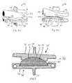
- FIG. 5is a front sectional view of an alternative customized implant in accordance with the present invention.
- FIGS. 6 a - ddepict a trial implant in a) a front, top and left side perspective view, b) a front view, c) a left side view and d) a front, top and left side perspective view and with a vertebra surface cutting tool therein.
- FIG. 7is a schematic representation of the apparatus used in making the customized implant.
- the present inventionis useful with either a damaged vertebra or, where appropriate or where a disc replacement is otherwise being made, with malformed vertebra.
- the present inventionis used with malformed vertebrae, it will be appreciated that there will be a targeted vertebra whose abnormality is being compensated for or two adjacent targeted vertebra whose common disc is being replaced. While the targeted vertebra (or adjacent vertebrae) may contribute only to a part of the overall deformed curvature as in scoliosis, correction of that vertebra (or vertebrae) may be desired to reduce the overall curvature and achieve a meaningful improvement in the undesired curvature.
- the targeted vertebra or both targeted vertebrae on either side of the disc being replacedmay be overcompensated for in order to help correct the undesired curvature of the adjacent vertebra.
- this overcompensationwill still be referred to as “natural” even though it is beyond what would be the compensation to the “natural” surface location of a damaged vertebra which would not have adjacent vertebrae contributing to the curvature.
- FIGS. 1 a , 1 b and 1 cdifferent views of a series 10 of vertebrae 12 , 14 and 16 .
- vertebra 14has been damaged and hence is abnormal due to trauma or the like.
- the vertebra in series 10will be referred to as abnormal vertebra 14 , superior (to vertebra 14 ) vertebra 12 and inferior (to vertebra 14 ) vertebra 16 .
- the damage and resultant malformation of abnormal vertebra 14causes series 10 to be compressed and deformed, as shown by the curves of axes 18 a , 18 b and 18 c in the FIGS. 1 a - c . It is this deformity which the present invention is designed to compensate for while retaining abnormal vertebra 14 in place.
- a 3D anatomy of series 10is obtained. This is simply and conveniently done with a CT scanning device 60 or the like (see FIG. 6 ), with slices smaller than 1 mm preferred, and optimally between 0.2-1 mm. A high resolution for the slices is required since the deformity of abnormal vertebra 14 must be determined from the CT scan slices. It will be appreciated that the 3D anatomy of all three vertebra of series 10 is required since the proper positioning of abnormal vertebra 14 must also be determined using the obtained 3D anatomy. It will be appreciated that other scanning devices besides a CT scanning device can be used so long as they produce a three dimensional anatomy or the like of the series 10 .
- the 3D anatomy of series 10With the 3D anatomy of series 10 obtained and loaded into a computer 62 , the 3D anatomy are depicted in a suitable screen 64 or the like as by the appearances of FIG. 1 .
- the useris able using standard software typical in the art to reposition each vertebra of series 10 so that vertebrae 12 , 14 and 16 are returned to their natural or desired (including for scoliosis, overcompensated for) positions and/or orientations, that is with axes 18 a ′, 18 b ′ and 18 c ′ now straight lines.
- abnormal vertebra 14With such a repositioned 3D anatomy, the user is able to determine (see) what surface of abnormal vertebra 14 has been abnormal and is causing the deformity (or for scoliosis, how far the two surfaces adjacent to the disc to be replaced should be moved). In this example, it is inferior surface 20 of abnormal vertebra 14 which has been damaged, as best shown in FIG. 2 b.
- the useris then able to determine where a desired surface 20 ′ of abnormal vertebra 14 would be if vertebra 14 were not damaged.
- the softwarethen also determines an approximate gap between abnormal surface 20 and a desired surface 20 ′. With this gap determined, an intervertebral implant 30 is constructed.
- the constructionadvantageously takes places by downloading or transferring of data from computer 62 with suitable software to a CAD/CAM milling machine 66 or the like.
- the abnormal surface 20is preferably smoothed somewhat in the computer before the gap is determined. This smoothing is performed because an exact match of abnormal surface with every (small) peak and valley of the abnormal is not needed; and to some extent, the smoothing will be dependent on the milling machine which is used and the degree of matching attainable with the milling process.
- Implant 30is shown in position in series 10 in FIGS. 3 a - c .
- implant 30is preferably of the type which allows relative movement between opposed endplates 32 and 34 , and hence relative movement of the adjacent vertebrae, as shown in the above identified published applications.
- the present inventionnot only provides a customized treatment for abnormal vertebrae, but does so in a manner which allows relative movement between the abnormal vertebra and the adjacent vertebra on the opposite side of the intervertebral space in which implant 30 is inserted. Instruments for insertion of the implant are also shown in the above referenced published applications. It will be appreciated that implant 30 has replaced the disc (not shown, and typically damaged as well) between abnormal vertebra 14 and inferior vertebra 16 . Implant 30 is constructed so that the desired (straight) axes 18 ′ shown in FIG. 2 are maintained after implantation of implant 30 .
- FIGS. 6 a - cshow this type of trial implant 70 , but after being formed to the custom shape using the features of the present invention, in order to fit into the intervertebral space.
- a tool 72is used which is constructed as shown in published application No. 2004/021519. Tool 72 has a suitably angled base end which fits into and is oriented by angled reception slot 74 .
- implant 30which is of the type which allows relative universal movement between the endplates, is customized as shown in FIG. 4 .
- implant 30(see the above referenced published applications for further details of implant 30 as well as similar implant 50 ′ in FIG. 5 ) is constructed of a superior endplate 32 and an inferior endplate 34 .
- Superior endplate 32has an upper vertebral surface engaging surface 36 which is designed to engage abnormal surface 20 and be secured thereto via keel 38 .
- inferior endplate 34has a lower vertebral surface engaging surface 40 which is designed to engage normal surface 22 of inferior vertebra 16 and be secured thereto via keel 42 .
- universal joint 44is formed by: a) an inlay 46 having a convex upper surface 48 , where inlay 46 is securely received in inferior endplate 34 ; and b) a mating concave lower surface 50 (not seen, but shown in published application 2005/0085917) formed in superior endplate 34 .
- superior endplate 32would have a constant thickness or height like that of inferior endplate 34 .
- upper surface 36 of superior endplate 32has been built up appropriately to fill this gap.
- upper surface 36has occurred over most of upper surface 36 thereof, starting from the right (as viewed) and building up to the left as well as back to front.
- built up upper surface 36is not necessarily planar, or even angled in any one plane; rather it may be undulating, or as shown in FIG. 4 , built up left to right as well as back to front with some curvature therealong.
- the deformity of abnormal vertebra 14is compensated for in more than one plane in this depicted embodiment.
- FIG. 5Depicted in FIG. 5 is a second embodiment of an implant 30 ′ which has been customized in accordance with the present invention.
- Implant 30 ′is broadly similar to implant 30 described above, and thus the same identifying numbers but with a prime (′) thereafter will be used for the same or similar elements.
- implant 30 ′is designed for use with an abnormal vertebra having an abnormal superior surface, which in the first embodiment would have occasioned a customized lower vertebral surface engaging surface 40 .
- neither lower vertebral surface engaging surface 40 ′ nor upper vertebral surface engaging surface 36 ′have been customized.
- inlay 46 ′has been customized so that one side, the left side as viewed, is higher (has a greater thickness) than the right side.
- This higher left sidecauses, upon implantation, lower vertebral surface engaging surface 40 ′ to be angled as shown to compensate for the damage to the adjacent vertebral superior surface when the universal joint 44 ′ is at the neutral or centered position (which is shown in FIG. 5 ).
- inlay 46 ′is the element which provides the compensation
- implant 30 ′is usable primarily where the abnormal surface of the vertebra is relatively planar.
- the use of a customized inlaymay afford some advantages, such as easier and quicker fabrication since inlay 46 ′ is formed of polyethylene.
- implant 30 or 30 ′can be designed to overcompensate for the curvature so that the remaining malformed vertebra are advantageously oriented relative to the implant.
- both endplates of implant 30could have customized (built up) surfaces, or both the inlay of implant 30 ′ and the other endplate surface 36 ′ could be customized (built up).
- the opposite facing surface of endplate 32could be built up in the same manner as inlay 46 .
Landscapes
- Health & Medical Sciences (AREA)
- Orthopedic Medicine & Surgery (AREA)
- Engineering & Computer Science (AREA)
- Transplantation (AREA)
- Biomedical Technology (AREA)
- Heart & Thoracic Surgery (AREA)
- Public Health (AREA)
- Oral & Maxillofacial Surgery (AREA)
- Veterinary Medicine (AREA)
- Cardiology (AREA)
- General Health & Medical Sciences (AREA)
- Vascular Medicine (AREA)
- Life Sciences & Earth Sciences (AREA)
- Animal Behavior & Ethology (AREA)
- Physics & Mathematics (AREA)
- Geometry (AREA)
- Manufacturing & Machinery (AREA)
- Physical Education & Sports Medicine (AREA)
- Neurology (AREA)
- Prostheses (AREA)
Abstract
Description
Claims (21)
Priority Applications (3)
| Application Number | Priority Date | Filing Date | Title |
|---|---|---|---|
| US11/150,468US8394142B2 (en) | 2005-06-13 | 2005-06-13 | Customizing an intervertebral implant |
| PCT/US2006/021313WO2006138067A2 (en) | 2005-06-13 | 2006-05-31 | Customizing an intervertebral implant |
| TW095120728ATW200722065A (en) | 2005-06-13 | 2006-06-12 | Customizing an intervertebral implant |
Applications Claiming Priority (1)
| Application Number | Priority Date | Filing Date | Title |
|---|---|---|---|
| US11/150,468US8394142B2 (en) | 2005-06-13 | 2005-06-13 | Customizing an intervertebral implant |
Publications (2)
| Publication Number | Publication Date |
|---|---|
| US20060282020A1 US20060282020A1 (en) | 2006-12-14 |
| US8394142B2true US8394142B2 (en) | 2013-03-12 |
Family
ID=37525005
Family Applications (1)
| Application Number | Title | Priority Date | Filing Date |
|---|---|---|---|
| US11/150,468Active2027-04-01US8394142B2 (en) | 2005-06-13 | 2005-06-13 | Customizing an intervertebral implant |
Country Status (3)
| Country | Link |
|---|---|
| US (1) | US8394142B2 (en) |
| TW (1) | TW200722065A (en) |
| WO (1) | WO2006138067A2 (en) |
Cited By (32)
| Publication number | Priority date | Publication date | Assignee | Title |
|---|---|---|---|---|
| US20150305878A1 (en)* | 2014-04-24 | 2015-10-29 | DePuy Synthes Products, LLC | Patient-Specific Spinal Fusion Cage and Methods of Making Same |
| US9693882B2 (en) | 2014-06-03 | 2017-07-04 | DePuy Synthes Products, Inc. | Optical trial device |
| US10045824B2 (en) | 2013-10-18 | 2018-08-14 | Medicrea International | Methods, systems, and devices for designing and manufacturing a rod to support a vertebral column of a patient |
| US10292770B2 (en) | 2017-04-21 | 2019-05-21 | Medicrea International | Systems, methods, and devices for developing patient-specific spinal treatments, operations, and procedures |
| US10318655B2 (en) | 2013-09-18 | 2019-06-11 | Medicrea International | Method making it possible to produce the ideal curvature of a rod of vertebral osteosynthesis material designed to support a patient's vertebral column |
| US10456211B2 (en) | 2015-11-04 | 2019-10-29 | Medicrea International | Methods and apparatus for spinal reconstructive surgery and measuring spinal length and intervertebral spacing, tension and rotation |
| US10902944B1 (en) | 2020-01-06 | 2021-01-26 | Carlsmed, Inc. | Patient-specific medical procedures and devices, and associated systems and methods |
| US10918422B2 (en) | 2017-12-01 | 2021-02-16 | Medicrea International | Method and apparatus for inhibiting proximal junctional failure |
| US11083586B2 (en) | 2017-12-04 | 2021-08-10 | Carlsmed, Inc. | Systems and methods for multi-planar orthopedic alignment |
| US11112770B2 (en) | 2017-11-09 | 2021-09-07 | Carlsmed, Inc. | Systems and methods for assisting a surgeon and producing patient-specific medical devices |
| US11166764B2 (en) | 2017-07-27 | 2021-11-09 | Carlsmed, Inc. | Systems and methods for assisting and augmenting surgical procedures |
| US11376076B2 (en) | 2020-01-06 | 2022-07-05 | Carlsmed, Inc. | Patient-specific medical systems, devices, and methods |
| USD958151S1 (en) | 2018-07-30 | 2022-07-19 | Carlsmed, Inc. | Display screen with a graphical user interface for surgical planning |
| US11432943B2 (en) | 2018-03-14 | 2022-09-06 | Carlsmed, Inc. | Systems and methods for orthopedic implant fixation |
| US11439514B2 (en) | 2018-04-16 | 2022-09-13 | Carlsmed, Inc. | Systems and methods for orthopedic implant fixation |
| US11443838B1 (en) | 2022-02-23 | 2022-09-13 | Carlsmed, Inc. | Non-fungible token systems and methods for storing and accessing healthcare data |
| US11612436B2 (en) | 2016-12-12 | 2023-03-28 | Medicrea International | Systems, methods, and devices for developing patient-specific medical treatments, operations, and procedures |
| US11696833B2 (en) | 2018-09-12 | 2023-07-11 | Carlsmed, Inc. | Systems and methods for orthopedic implants |
| US11769251B2 (en) | 2019-12-26 | 2023-09-26 | Medicrea International | Systems and methods for medical image analysis |
| US11793577B1 (en) | 2023-01-27 | 2023-10-24 | Carlsmed, Inc. | Techniques to map three-dimensional human anatomy data to two-dimensional human anatomy data |
| US11806241B1 (en) | 2022-09-22 | 2023-11-07 | Carlsmed, Inc. | System for manufacturing and pre-operative inspecting of patient-specific implants |
| US11877801B2 (en) | 2019-04-02 | 2024-01-23 | Medicrea International | Systems, methods, and devices for developing patient-specific spinal implants, treatments, operations, and/or procedures |
| US11925417B2 (en) | 2019-04-02 | 2024-03-12 | Medicrea International | Systems, methods, and devices for developing patient-specific spinal implants, treatments, operations, and/or procedures |
| US12127769B2 (en) | 2020-11-20 | 2024-10-29 | Carlsmed, Inc. | Patient-specific jig for personalized surgery |
| US12133803B2 (en) | 2018-11-29 | 2024-11-05 | Carlsmed, Inc. | Systems and methods for orthopedic implants |
| US12226315B2 (en) | 2020-08-06 | 2025-02-18 | Carlsmed, Inc. | Kinematic data-based patient-specific artificial discs, implants and associated systems and methods |
| US12232885B2 (en) | 2023-01-09 | 2025-02-25 | Carlsmed, Inc. | System for modeling patient spinal changes |
| US12232980B2 (en) | 2021-06-08 | 2025-02-25 | Carlsmed, Inc. | Patient-specific expandable spinal implants and associated systems and methods |
| US12274510B2 (en) | 2023-02-06 | 2025-04-15 | Carlsmed, Inc. | Patient-specific implant design and manufacturing system with a surgical implant positioning manager |
| US12274511B2 (en) | 2019-04-02 | 2025-04-15 | Medicrea International | Systems and methods for medical image analysis |
| US12318144B2 (en) | 2021-06-23 | 2025-06-03 | Medicrea International SA | Systems and methods for planning a patient-specific spinal correction |
| US12390276B2 (en) | 2021-11-01 | 2025-08-19 | Carlsmed, Inc. | Spinal implants and surgical procedures with reduced subsidence, and associated systems and methods |
Families Citing this family (23)
| Publication number | Priority date | Publication date | Assignee | Title |
|---|---|---|---|---|
| US7494507B2 (en) | 2000-01-30 | 2009-02-24 | Diamicron, Inc. | Articulating diamond-surfaced spinal implants |
| US8038713B2 (en) | 2002-04-23 | 2011-10-18 | Spinecore, Inc. | Two-component artificial disc replacements |
| US20080027548A9 (en) | 2002-04-12 | 2008-01-31 | Ferree Bret A | Spacerless artificial disc replacements |
| US6706068B2 (en) | 2002-04-23 | 2004-03-16 | Bret A. Ferree | Artificial disc replacements with natural kinematics |
| US6908484B2 (en) | 2003-03-06 | 2005-06-21 | Spinecore, Inc. | Cervical disc replacement |
| US8246680B2 (en)* | 2006-05-25 | 2012-08-21 | Spinemedica, Llc | Patient-specific spinal implants and related systems and methods |
| WO2008098228A2 (en) | 2007-02-09 | 2008-08-14 | Diamicron, Inc. | Multi-lobe artificial spine joint |
| US20110092859A1 (en)* | 2007-06-25 | 2011-04-21 | Neubardt Seth L | System for determining and placing spinal implants or prostheses |
| US20090024164A1 (en)* | 2007-06-25 | 2009-01-22 | Neubardt Seth L | System for determining spinal implants |
| US8549888B2 (en) | 2008-04-04 | 2013-10-08 | Nuvasive, Inc. | System and device for designing and forming a surgical implant |
| KR101072732B1 (en)* | 2009-04-01 | 2011-10-11 | 국립암센터 | Bone graft shaping system and method using the same |
| US9901455B2 (en) | 2009-11-25 | 2018-02-27 | Nathan C. Moskowitz | Total artificial spino-laminar prosthetic replacement |
| US11207132B2 (en) | 2012-03-12 | 2021-12-28 | Nuvasive, Inc. | Systems and methods for performing spinal surgery |
| US20140081659A1 (en) | 2012-09-17 | 2014-03-20 | Depuy Orthopaedics, Inc. | Systems and methods for surgical and interventional planning, support, post-operative follow-up, and functional recovery tracking |
| US9848922B2 (en) | 2013-10-09 | 2017-12-26 | Nuvasive, Inc. | Systems and methods for performing spine surgery |
| US10709509B2 (en) | 2014-06-17 | 2020-07-14 | Nuvasive, Inc. | Systems and methods for planning, performing, and assessing spinal correction during surgery |
| US10433893B1 (en) | 2014-10-17 | 2019-10-08 | Nuvasive, Inc. | Systems and methods for performing spine surgery |
| AU2017214484B2 (en)* | 2016-02-02 | 2019-12-12 | Nexus TDR, Inc. | Systems and methods for patient-specific total disc replacement |
| AU2017204355B2 (en) | 2016-07-08 | 2021-09-09 | Mako Surgical Corp. | Scaffold for alloprosthetic composite implant |
| WO2020113276A1 (en)* | 2018-12-06 | 2020-06-11 | 3Dmorphic Pty Ltd | An implantable medical device |
| US11452618B2 (en) | 2019-09-23 | 2022-09-27 | Dimicron, Inc | Spinal artificial disc removal tool |
| JP6784378B1 (en)* | 2020-06-24 | 2020-11-11 | 国立大学法人京都大学 | Methods and programs for designing intervertebral spacers |
| TWI789143B (en)* | 2021-12-03 | 2023-01-01 | 財團法人工業技術研究院 | Aritificial intervertebral disk |
Citations (37)
| Publication number | Priority date | Publication date | Assignee | Title |
|---|---|---|---|---|
| US4109383A (en) | 1976-06-21 | 1978-08-29 | Reed Gerald M | Dental implant bender |
| US4575805A (en) | 1980-12-24 | 1986-03-11 | Moermann Werner H | Method and apparatus for the fabrication of custom-shaped implants |
| US4936862A (en)* | 1986-05-30 | 1990-06-26 | Walker Peter S | Method of designing and manufacturing a human joint prosthesis |
| US5147404A (en) | 1987-12-07 | 1992-09-15 | Downey Ernest L | Vertebra prosthesis |
| US5261913A (en) | 1989-07-26 | 1993-11-16 | J.B.S. Limited Company | Device for straightening, securing, compressing and elongating the spinal column |
| US5314477A (en) | 1990-03-07 | 1994-05-24 | J.B.S. Limited Company | Prosthesis for intervertebral discs and instruments for implanting it |
| US5514180A (en) | 1994-01-14 | 1996-05-07 | Heggeness; Michael H. | Prosthetic intervertebral devices |
| US5527315A (en) | 1994-04-21 | 1996-06-18 | Jbs S.A. | Spinal osteosynthesis rod with three branches |
| US5658285A (en) | 1994-10-28 | 1997-08-19 | Jbs S.A. | Rehabitable connecting-screw device for a bone joint, intended in particular for stabilizing at least two vertebrae |
| US5723013A (en) | 1995-02-06 | 1998-03-03 | Jbs S.A. | Spacer implant for substituting missing vertebrae |
| US5741215A (en) | 1993-09-10 | 1998-04-21 | The University Of Queensland | Stereolithographic anatomical modelling process |
| US5798924A (en)* | 1993-12-04 | 1998-08-25 | Eufinger; Harald | Process for producing endoprostheses |
| US5824085A (en)* | 1996-09-30 | 1998-10-20 | Integrated Surgical Systems, Inc. | System and method for cavity generation for surgical planning and initial placement of a bone prosthesis |
| US5865846A (en)* | 1994-11-14 | 1999-02-02 | Bryan; Vincent | Human spinal disc prosthesis |
| US5895428A (en) | 1996-11-01 | 1999-04-20 | Berry; Don | Load bearing spinal joint implant |
| DE19747979A1 (en) | 1997-10-30 | 1999-05-06 | Michael Dipl Ing Wehmoeller | Method of manufacturing individual bone replacement for reconstructive surgery |
| DE19922279A1 (en)* | 1999-05-11 | 2000-11-16 | Friedrich Schiller Uni Jena Bu | Procedure for generating patient-specific implants |
| WO2001019295A1 (en) | 1999-09-14 | 2001-03-22 | Spine Solutions Inc. | Instrument for inserting intervertebral implants |
| US6254639B1 (en)* | 1996-09-25 | 2001-07-03 | Ninian Peckitt | Prosthetic implants |
| US6470207B1 (en) | 1999-03-23 | 2002-10-22 | Surgical Navigation Technologies, Inc. | Navigational guidance via computer-assisted fluoroscopic imaging |
| US6503279B1 (en) | 1996-09-04 | 2003-01-07 | Synthes (Usa) | Intervertebral implant |
| US6510334B1 (en)* | 2000-11-14 | 2003-01-21 | Luis Schuster | Method of producing an endoprosthesis as a joint substitute for a knee joint |
| US20040117022A1 (en) | 2002-12-13 | 2004-06-17 | Theirry Marnay | Intervertebral implant, insertion tool and method of inserting same |
| US20040215198A1 (en) | 2003-04-28 | 2004-10-28 | Spine Solutions, Inc. | Instruments and method for preparing an intervertebral space for receiving an artificial disc implant |
| US20040225362A1 (en) | 2003-05-06 | 2004-11-11 | Marc Richelsoph | Artificial intervertebral disc |
| WO2004110309A2 (en) | 2003-06-11 | 2004-12-23 | Case Western Reserve University | Computer-aided-design of skeletal implants |
| US20050021042A1 (en) | 2003-07-21 | 2005-01-27 | Theirry Marnay | Instruments and method for inserting an intervertebral implant |
| US20050022098A1 (en)* | 2002-05-13 | 2005-01-27 | Vayanos Alkinoos Hector | Data delivery in conjunction with a hybrid automatic retransmission mechanism in CDMA communication systems |
| US6849223B2 (en) | 2001-04-19 | 2005-02-01 | Case Western Reserve University | Fabrication of a polymeric prosthetic implant |
| US20050027362A1 (en) | 1999-02-26 | 2005-02-03 | Williams Lytton A. | Method and apparatus for intervertebral implant anchorage |
| US20050043835A1 (en) | 2002-09-30 | 2005-02-24 | Medical Modeling Llc | Method for design and production of custom-fit prosthesis |
| US20050043799A1 (en) | 1999-10-22 | 2005-02-24 | Archus Orthopedics Inc. | Facet arthroplasty devices and methods |
| US20050049707A1 (en) | 2003-08-29 | 2005-03-03 | Ferree Bret A. | Cemented artificial disc replacements |
| US20050055029A1 (en)* | 2003-09-10 | 2005-03-10 | Sdgi Holdings, Inc. | Artificial spinal discs and associated implantation instruments and methods |
| US20050060034A1 (en) | 2003-09-15 | 2005-03-17 | Sdgi Holdings, Inc. | Revisable prosthetic device |
| US20050085917A1 (en) | 1999-07-02 | 2005-04-21 | Thierry Marnay | Intervertebral implant |
| US6896701B2 (en) | 2001-01-22 | 2005-05-24 | Sdgi Holdings, Inc. | Modular interbody fusion implant |
- 2005
- 2005-06-13USUS11/150,468patent/US8394142B2/enactiveActive
- 2006
- 2006-05-31WOPCT/US2006/021313patent/WO2006138067A2/enactiveApplication Filing
- 2006-06-12TWTW095120728Apatent/TW200722065A/enunknown
Patent Citations (39)
| Publication number | Priority date | Publication date | Assignee | Title |
|---|---|---|---|---|
| US4109383A (en) | 1976-06-21 | 1978-08-29 | Reed Gerald M | Dental implant bender |
| US4575805A (en) | 1980-12-24 | 1986-03-11 | Moermann Werner H | Method and apparatus for the fabrication of custom-shaped implants |
| US4936862A (en)* | 1986-05-30 | 1990-06-26 | Walker Peter S | Method of designing and manufacturing a human joint prosthesis |
| US5147404A (en) | 1987-12-07 | 1992-09-15 | Downey Ernest L | Vertebra prosthesis |
| US5261913A (en) | 1989-07-26 | 1993-11-16 | J.B.S. Limited Company | Device for straightening, securing, compressing and elongating the spinal column |
| US5314477A (en) | 1990-03-07 | 1994-05-24 | J.B.S. Limited Company | Prosthesis for intervertebral discs and instruments for implanting it |
| US5741215A (en) | 1993-09-10 | 1998-04-21 | The University Of Queensland | Stereolithographic anatomical modelling process |
| US5798924A (en)* | 1993-12-04 | 1998-08-25 | Eufinger; Harald | Process for producing endoprostheses |
| US5514180A (en) | 1994-01-14 | 1996-05-07 | Heggeness; Michael H. | Prosthetic intervertebral devices |
| US5527315A (en) | 1994-04-21 | 1996-06-18 | Jbs S.A. | Spinal osteosynthesis rod with three branches |
| US5658285A (en) | 1994-10-28 | 1997-08-19 | Jbs S.A. | Rehabitable connecting-screw device for a bone joint, intended in particular for stabilizing at least two vertebrae |
| US5865846A (en)* | 1994-11-14 | 1999-02-02 | Bryan; Vincent | Human spinal disc prosthesis |
| US5723013A (en) | 1995-02-06 | 1998-03-03 | Jbs S.A. | Spacer implant for substituting missing vertebrae |
| US6503279B1 (en) | 1996-09-04 | 2003-01-07 | Synthes (Usa) | Intervertebral implant |
| US6254639B1 (en)* | 1996-09-25 | 2001-07-03 | Ninian Peckitt | Prosthetic implants |
| US5824085A (en)* | 1996-09-30 | 1998-10-20 | Integrated Surgical Systems, Inc. | System and method for cavity generation for surgical planning and initial placement of a bone prosthesis |
| US5895428A (en) | 1996-11-01 | 1999-04-20 | Berry; Don | Load bearing spinal joint implant |
| DE19747979A1 (en) | 1997-10-30 | 1999-05-06 | Michael Dipl Ing Wehmoeller | Method of manufacturing individual bone replacement for reconstructive surgery |
| US20050027362A1 (en) | 1999-02-26 | 2005-02-03 | Williams Lytton A. | Method and apparatus for intervertebral implant anchorage |
| US6470207B1 (en) | 1999-03-23 | 2002-10-22 | Surgical Navigation Technologies, Inc. | Navigational guidance via computer-assisted fluoroscopic imaging |
| US6932842B1 (en)* | 1999-05-11 | 2005-08-23 | 3Di Gmbh | Method for generating patient-specific implants |
| DE19922279A1 (en)* | 1999-05-11 | 2000-11-16 | Friedrich Schiller Uni Jena Bu | Procedure for generating patient-specific implants |
| US20050085917A1 (en) | 1999-07-02 | 2005-04-21 | Thierry Marnay | Intervertebral implant |
| WO2001019295A1 (en) | 1999-09-14 | 2001-03-22 | Spine Solutions Inc. | Instrument for inserting intervertebral implants |
| US20050043799A1 (en) | 1999-10-22 | 2005-02-24 | Archus Orthopedics Inc. | Facet arthroplasty devices and methods |
| US6510334B1 (en)* | 2000-11-14 | 2003-01-21 | Luis Schuster | Method of producing an endoprosthesis as a joint substitute for a knee joint |
| US6896701B2 (en) | 2001-01-22 | 2005-05-24 | Sdgi Holdings, Inc. | Modular interbody fusion implant |
| US6849223B2 (en) | 2001-04-19 | 2005-02-01 | Case Western Reserve University | Fabrication of a polymeric prosthetic implant |
| US20050022098A1 (en)* | 2002-05-13 | 2005-01-27 | Vayanos Alkinoos Hector | Data delivery in conjunction with a hybrid automatic retransmission mechanism in CDMA communication systems |
| US20050043835A1 (en) | 2002-09-30 | 2005-02-24 | Medical Modeling Llc | Method for design and production of custom-fit prosthesis |
| US20040117022A1 (en) | 2002-12-13 | 2004-06-17 | Theirry Marnay | Intervertebral implant, insertion tool and method of inserting same |
| US20040215198A1 (en) | 2003-04-28 | 2004-10-28 | Spine Solutions, Inc. | Instruments and method for preparing an intervertebral space for receiving an artificial disc implant |
| US20040225362A1 (en) | 2003-05-06 | 2004-11-11 | Marc Richelsoph | Artificial intervertebral disc |
| WO2004110309A2 (en) | 2003-06-11 | 2004-12-23 | Case Western Reserve University | Computer-aided-design of skeletal implants |
| US20050021042A1 (en) | 2003-07-21 | 2005-01-27 | Theirry Marnay | Instruments and method for inserting an intervertebral implant |
| US20050049707A1 (en) | 2003-08-29 | 2005-03-03 | Ferree Bret A. | Cemented artificial disc replacements |
| US20050055029A1 (en)* | 2003-09-10 | 2005-03-10 | Sdgi Holdings, Inc. | Artificial spinal discs and associated implantation instruments and methods |
| US20050055098A1 (en)* | 2003-09-10 | 2005-03-10 | Sdgi Holdings, Inc. | Artificial spinal discs and associated implantation and revision methods |
| US20050060034A1 (en) | 2003-09-15 | 2005-03-17 | Sdgi Holdings, Inc. | Revisable prosthetic device |
Non-Patent Citations (25)
| Title |
|---|
| Cranin AN, et al; An in vitro comparison of the computerized tomography/CAD-CAM and direct bone impression techniques for subperiosteal implant model generation; J Oral Implantol. 1998; 24(2):74-9. |
| Dean D, et al; Computer aided design of large-format prefabricated cranial plates; J Craniofac Surg. Nov. 2003; 14(6):819-32. |
| Eppley BL, et al; Computer-generated patient models for reconstruction of cranial and facial deformities; J Craniofac Surg. Nov. 1998; 9(6):548-56. |
| Eufiner H, et al; Computer-assisted prefabrication of individual craniofacial implants; AORN J. Nov. 2001; 74(5):648-54; quiz 655-6, 658-62. |
| Eufinger H, et al; Experimental computer-assisted alloplastic sandwich augmentation of the atrophic mandible; J Oral Maxillofac Surg. Dec. 1999; 57(12):1436-40; discussion 1440-1. |
| Eufinger H, et al; Individual prefabricated titanium implants in reconstructive craniofacial surgery: clinical and technical aspects of the first 22 cases; Plast Reconstr Surg. Aug. 1998; 202(2):300-8. |
| Eufinger H, et al; Prefabricated prostheses for the reconstruction of skull defects; Int J Oral Maxillofac Surg. Feb. 1995; 24(1 Pt 2):104-10. |
| Eufinger H, et al; Reconstruction of craniofacial bone defects with individual alloplastic implants based on CAD/CAM-manipulated CT-data; J Craniomaxillofac Surg. Jun. 1995; 23(3):175-81. |
| Eufinger H, et al; Single-step fronto-orbital resection and reconstruction with individual resection template and corresponding titanium implant: a new method of computer-aided surgery; J Craniomaxillofac Surg. Dec. 1998; 26(6):373-8. |
| Gulyas G, et al; Cranioplasty using computer-designed implants (preliminary report); Orv Hetil. Oct. 29, 1995; 136(44):2393-7. |
| Klein HM, et al; Stereolithographic model construction based on 3-dimensional reconstructed CT sectional image sequences; Rofo. May 1992; 156(5):429-32. |
| Langlotz F, et al; A pilot study on computer-assisted optimal contouring of orthopedic fixation devices; Comput Aided Surg. 1999; 4(6):305-13. |
| Lo LJ, et al; Computer-aided reconstruction of traumatic fronto-orbital osseous defects: aesthetic considerations; Chang Gung Med J. Apr. 2004; 27(4):283-91. |
| Lopponen H, et al; Computed tomography data based rapid prototyping model of the temporal bone before cochlear implant surgery; Acta Otolaryngol Suppl. 1997; 529:47-9. |
| Redl P, et al; Computer tomography in implantology; Fogorv Sz. May 1995; 88(5):169-72. |
| Schlieper J, et al; CT-computer-template-assisted planning of implant and magnet position in epi-prosthetic management of facial defects; Mund Kiefer Gesichtschir. Jan. 2001; 5(1):22-7. |
| Stojadinovic S, et al; One-step resection and reconstruction of the mandible using computer-aided techniques-experimental and clinical results; Mund Kiefer Gesichtschir. May 1999; 3 Suppl 1:S151-3. |
| Stojadinovic S, et al; One-step resection and reconstruction of the mandible using computer-aided techniques—experimental and clinical results; Mund Kiefer Gesichtschir. May 1999; 3 Suppl 1:S151-3. |
| Synthes Brochure, PSI Patient Specific Implants Derived from CT data for excellent reconstructive results, 2004. |
| Tal H, et al; A comparison of panoramic radiography with computer tomography in the planning of implant surgery; Dentomaxillofac Radiol. Feb. 1991; 20(1):40-2. |
| Teng Y, et al; Fabrication of custom-made artificial semi-knee joint based on rapid prototyping technique: three-dimensional reconstruction of femoral condyle; Zhongguo Xiu Fu Chong Jian Wai Ke Za Zhi. Jul. 2004; 18(4):257-60. |
| Truitt HP, et al; Morphologic replication of the mandible using a computerized tomography for the fabrication of a subperiosteal implant; Oral Surg Med Oral Pathol. May 1988; 65(5):499-504. |
| Van Steenberghe D, et al; Bone augmentation by means of a stiff occlusive titanium barrier; Clin. Oral Implants Res. Feb. 2003; 14(1):63-71. |
| Weihe S, et al: Synthesis of CAD/CAM, robotics and biomaterial implant fabrication: single-step reconstruction in computer-aided frontotemporal bone resection; Int J Oral Maxillofac Surg. Oct. 2000; 29(5):384-8. |
| Wurm G, et al; Prospective study on cranioplasty with individual carbon fiber reinforced polymer (CFRP) implants produced by means of stereolithography; Surg Neurol. Dec. 2004; 62(6):510-21. |
Cited By (69)
| Publication number | Priority date | Publication date | Assignee | Title |
|---|---|---|---|---|
| US10318655B2 (en) | 2013-09-18 | 2019-06-11 | Medicrea International | Method making it possible to produce the ideal curvature of a rod of vertebral osteosynthesis material designed to support a patient's vertebral column |
| US12417323B2 (en) | 2013-09-18 | 2025-09-16 | Medicrea International | Method of making it possible to produce and ideal curvature of a rod of vertebral osteosynthesis material designed to support a patient's vertebral column |
| US10970426B2 (en) | 2013-09-18 | 2021-04-06 | Medicrea International SA | Methods, systems, and devices for designing and manufacturing a spinal rod |
| US12019955B2 (en) | 2013-09-18 | 2024-06-25 | Medicrea International | Method making it possible to produce the ideal curvature of a rod of vertebral osteosynthesis material designed to support a patient's vertebral column |
| US10433913B2 (en) | 2013-10-18 | 2019-10-08 | Medicrea International | Methods, systems, and devices for designing and manufacturing a spinal rod |
| US10973582B2 (en) | 2013-10-18 | 2021-04-13 | Medicrea International | Methods, systems, and devices for designing and manufacturing a spinal rod |
| US11197719B2 (en) | 2013-10-18 | 2021-12-14 | Medicrea International | Methods, systems, and devices for designing and manufacturing a spinal rod |
| US11197718B2 (en) | 2013-10-18 | 2021-12-14 | Medicrea Iniernational | Methods, systems, and devices for designing and manufacturing a spinal rod |
| US10413365B1 (en) | 2013-10-18 | 2019-09-17 | Medicrea International | Methods, systems, and devices for designing and manufacturing a spinal rod |
| US10420615B1 (en) | 2013-10-18 | 2019-09-24 | Medicrea International | Methods, systems, and devices for designing and manufacturing a spinal rod |
| US10426553B2 (en) | 2013-10-18 | 2019-10-01 | Medicrea International | Methods, systems, and devices for designing and manufacturing a spinal rod |
| US10433912B1 (en) | 2013-10-18 | 2019-10-08 | Medicrea International | Methods, systems, and devices for designing and manufacturing a spinal rod |
| US11918295B2 (en) | 2013-10-18 | 2024-03-05 | Medicrea International | Methods, systems, and devices for designing and manufacturing a spinal rod |
| US10441363B1 (en) | 2013-10-18 | 2019-10-15 | Medicrea International | Methods, systems, and devices for designing and manufacturing a spinal rod |
| US12257000B2 (en) | 2013-10-18 | 2025-03-25 | Medicrea International | Methods, systems, and devices for designing and manufacturing a spinal rod |
| US10314657B2 (en) | 2013-10-18 | 2019-06-11 | Medicrea International | Methods, systems, and devices for designing and manufacturing a spinal rod |
| US10045824B2 (en) | 2013-10-18 | 2018-08-14 | Medicrea International | Methods, systems, and devices for designing and manufacturing a rod to support a vertebral column of a patient |
| US20150305878A1 (en)* | 2014-04-24 | 2015-10-29 | DePuy Synthes Products, LLC | Patient-Specific Spinal Fusion Cage and Methods of Making Same |
| US9757245B2 (en)* | 2014-04-24 | 2017-09-12 | DePuy Synthes Products, Inc. | Patient-specific spinal fusion cage and methods of making same |
| US10405987B2 (en) | 2014-04-24 | 2019-09-10 | DePuy Synthes Products, Inc. | Patient-specific spinal fusion cage and methods of making same |
| US9693882B2 (en) | 2014-06-03 | 2017-07-04 | DePuy Synthes Products, Inc. | Optical trial device |
| US10456211B2 (en) | 2015-11-04 | 2019-10-29 | Medicrea International | Methods and apparatus for spinal reconstructive surgery and measuring spinal length and intervertebral spacing, tension and rotation |
| US12178516B2 (en) | 2016-12-12 | 2024-12-31 | Medicrea International | Systems, methods, and devices for developing patient-specific medical treatments, operations, and procedures |
| US11612436B2 (en) | 2016-12-12 | 2023-03-28 | Medicrea International | Systems, methods, and devices for developing patient-specific medical treatments, operations, and procedures |
| US12004814B2 (en) | 2017-04-21 | 2024-06-11 | Medicrea International | Systems, methods, and devices for developing patient-specific spinal treatments, operations, and procedures |
| US11185369B2 (en) | 2017-04-21 | 2021-11-30 | Medicrea Nternational | Systems, methods, and devices for developing patient-specific spinal treatments, operations, and procedures |
| US10292770B2 (en) | 2017-04-21 | 2019-05-21 | Medicrea International | Systems, methods, and devices for developing patient-specific spinal treatments, operations, and procedures |
| US11497559B1 (en) | 2017-07-27 | 2022-11-15 | Carlsmed, Inc. | Systems and methods for physician designed surgical procedures |
| US12274509B2 (en) | 2017-07-27 | 2025-04-15 | Carlsmed, Inc. | Systems and methods for physician designed surgical procedures |
| US11857264B2 (en) | 2017-07-27 | 2024-01-02 | Carlsmed, Inc. | Systems and methods for physician designed surgical procedures |
| US12274506B2 (en) | 2017-07-27 | 2025-04-15 | Carlsmed, Inc. | Systems and methods for assisting and augmenting surgical procedures |
| US11166764B2 (en) | 2017-07-27 | 2021-11-09 | Carlsmed, Inc. | Systems and methods for assisting and augmenting surgical procedures |
| US11112770B2 (en) | 2017-11-09 | 2021-09-07 | Carlsmed, Inc. | Systems and methods for assisting a surgeon and producing patient-specific medical devices |
| US10918422B2 (en) | 2017-12-01 | 2021-02-16 | Medicrea International | Method and apparatus for inhibiting proximal junctional failure |
| US11083586B2 (en) | 2017-12-04 | 2021-08-10 | Carlsmed, Inc. | Systems and methods for multi-planar orthopedic alignment |
| US12427025B2 (en) | 2017-12-04 | 2025-09-30 | Carlsmed, Inc. | Systems and methods for multi-planar orthopedic alignment |
| US11432943B2 (en) | 2018-03-14 | 2022-09-06 | Carlsmed, Inc. | Systems and methods for orthopedic implant fixation |
| US12251320B2 (en) | 2018-04-16 | 2025-03-18 | Carlsmed, Inc. | Systems and methods for orthopedic implant fixation |
| US12245952B2 (en) | 2018-04-16 | 2025-03-11 | Carlsmed, Inc. | Systems and methods for orthopedic implant fixation |
| US11439514B2 (en) | 2018-04-16 | 2022-09-13 | Carlsmed, Inc. | Systems and methods for orthopedic implant fixation |
| USD958151S1 (en) | 2018-07-30 | 2022-07-19 | Carlsmed, Inc. | Display screen with a graphical user interface for surgical planning |
| US11717412B2 (en) | 2018-09-12 | 2023-08-08 | Carlsmed, Inc. | Systems and methods for orthopedic implants |
| US12251313B2 (en) | 2018-09-12 | 2025-03-18 | Carlsmed, Inc. | Systems and methods for orthopedic implants |
| US11696833B2 (en) | 2018-09-12 | 2023-07-11 | Carlsmed, Inc. | Systems and methods for orthopedic implants |
| US12133803B2 (en) | 2018-11-29 | 2024-11-05 | Carlsmed, Inc. | Systems and methods for orthopedic implants |
| US12274622B2 (en) | 2018-11-29 | 2025-04-15 | Carlsmed, Inc. | Systems and methods for orthopedic implants |
| US12274511B2 (en) | 2019-04-02 | 2025-04-15 | Medicrea International | Systems and methods for medical image analysis |
| US11925417B2 (en) | 2019-04-02 | 2024-03-12 | Medicrea International | Systems, methods, and devices for developing patient-specific spinal implants, treatments, operations, and/or procedures |
| US11877801B2 (en) | 2019-04-02 | 2024-01-23 | Medicrea International | Systems, methods, and devices for developing patient-specific spinal implants, treatments, operations, and/or procedures |
| US12251165B2 (en) | 2019-04-02 | 2025-03-18 | Medicrea International | Systems, methods, and devices for developing patient-specific spinal implants, treatments, operations, and/or procedures |
| US11769251B2 (en) | 2019-12-26 | 2023-09-26 | Medicrea International | Systems and methods for medical image analysis |
| US12137983B2 (en) | 2020-01-06 | 2024-11-12 | Carlsmed, Inc. | Patient-specific medical systems, devices, and methods |
| US12376907B2 (en) | 2020-01-06 | 2025-08-05 | Carlsmed, Inc. | Patient-specific medical systems, devices, and methods |
| US11376076B2 (en) | 2020-01-06 | 2022-07-05 | Carlsmed, Inc. | Patient-specific medical systems, devices, and methods |
| US11854683B2 (en) | 2020-01-06 | 2023-12-26 | Carlsmed, Inc. | Patient-specific medical procedures and devices, and associated systems and methods |
| US10902944B1 (en) | 2020-01-06 | 2021-01-26 | Carlsmed, Inc. | Patient-specific medical procedures and devices, and associated systems and methods |
| US11678938B2 (en) | 2020-01-06 | 2023-06-20 | Carlsmed, Inc. | Patient-specific medical systems, devices, and methods |
| US12226315B2 (en) | 2020-08-06 | 2025-02-18 | Carlsmed, Inc. | Kinematic data-based patient-specific artificial discs, implants and associated systems and methods |
| US12127769B2 (en) | 2020-11-20 | 2024-10-29 | Carlsmed, Inc. | Patient-specific jig for personalized surgery |
| US12232980B2 (en) | 2021-06-08 | 2025-02-25 | Carlsmed, Inc. | Patient-specific expandable spinal implants and associated systems and methods |
| US12318144B2 (en) | 2021-06-23 | 2025-06-03 | Medicrea International SA | Systems and methods for planning a patient-specific spinal correction |
| US12390276B2 (en) | 2021-11-01 | 2025-08-19 | Carlsmed, Inc. | Spinal implants and surgical procedures with reduced subsidence, and associated systems and methods |
| US12142357B2 (en) | 2022-02-23 | 2024-11-12 | Carlsmed, Inc. | Non-fungible token systems and methods for storing and accessing healthcare data |
| US11443838B1 (en) | 2022-02-23 | 2022-09-13 | Carlsmed, Inc. | Non-fungible token systems and methods for storing and accessing healthcare data |
| US11984205B2 (en) | 2022-02-23 | 2024-05-14 | Carlsmed, Inc. | Non-fungible token systems and methods for storing and accessing healthcare data |
| US11806241B1 (en) | 2022-09-22 | 2023-11-07 | Carlsmed, Inc. | System for manufacturing and pre-operative inspecting of patient-specific implants |
| US12232885B2 (en) | 2023-01-09 | 2025-02-25 | Carlsmed, Inc. | System for modeling patient spinal changes |
| US11793577B1 (en) | 2023-01-27 | 2023-10-24 | Carlsmed, Inc. | Techniques to map three-dimensional human anatomy data to two-dimensional human anatomy data |
| US12274510B2 (en) | 2023-02-06 | 2025-04-15 | Carlsmed, Inc. | Patient-specific implant design and manufacturing system with a surgical implant positioning manager |
Also Published As
| Publication number | Publication date |
|---|---|
| WO2006138067A3 (en) | 2007-03-29 |
| TW200722065A (en) | 2007-06-16 |
| US20060282020A1 (en) | 2006-12-14 |
| WO2006138067A2 (en) | 2006-12-28 |
Similar Documents
| Publication | Publication Date | Title |
|---|---|---|
| US8394142B2 (en) | Customizing an intervertebral implant | |
| JP5698737B2 (en) | Intervertebral implant | |
| US20190021866A1 (en) | Patient-specific glenoid implant | |
| US20050065628A1 (en) | Customized prosthesis and method of designing and manufacturing a customized prosthesis by utilizing computed tomography data | |
| US8702805B2 (en) | Acetabulum surgical resurfacing aid | |
| AU2004268673B8 (en) | Multipiece allograft implant | |
| US20210093457A1 (en) | Bio-mechanically compatible 3D-printed intervertebral disc | |
| US20200155236A1 (en) | Systems and methods for customized spine guide using two-dimensional imaging | |
| US20080140204A1 (en) | Vertebral Implant Systems and Methods of Use | |
| CN102405032A (en) | Patient-adapted and improved orthopedic implants, designs and related tools | |
| US20220331124A1 (en) | Bio-mechanically compatible 3D-printed intervertebral disc | |
| US8366718B2 (en) | Preparation device for preparing an intervertebral disc compartment | |
| US12303406B2 (en) | Method of implanting an artificial disc replacement device | |
| JP2025507077A (en) | How to calculate the rod geometry of a pedicle screw system for spinal fixation | |
| ZA200605651B (en) | Instrument for the insertion of an intervertebral articular prosthesis | |
| EP3773260B1 (en) | Monoblock implant | |
| US8795376B2 (en) | Positioning insert for intervertebral disc disorder | |
| CN212630973U (en) | Interbody fusion cage and implantation tool | |
| AU2023100050A4 (en) | Integrally formed medical devices | |
| US20240277487A1 (en) | Interbody device incorporating lattice structure and related systems and methods | |
| JP2025507078A (en) | Method for determining intervertebral implant device parameters for an intervertebral implant device for spinal fusion surgery - Patents.com | |
| WO2021113174A2 (en) | Artificial disc replacement device and methods and instruments for implanting same | |
| CA2547986A1 (en) | Instrument set for inserting an intervertebral joint prosthesis | |
| HK1121661A (en) | Preparation device for preparing an intervertebral disc compartment |
Legal Events
| Date | Code | Title | Description |
|---|---|---|---|
| AS | Assignment | Owner name:SYNTHES (USA), PENNSYLVANIA Free format text:ASSIGNMENT OF ASSIGNORS INTEREST;ASSIGNORS:BERTAGNOLI, RUDOLPH;MARNAY, THIERRY;GEISERT, CHRISTOPHE;AND OTHERS;SIGNING DATES FROM 20050808 TO 20050929;REEL/FRAME:017132/0653 Owner name:SYNTHES (USA), PENNSYLVANIA Free format text:ASSIGNMENT OF ASSIGNORS INTEREST;ASSIGNORS:BERTAGNOLI, RUDOLPH;MARNAY, THIERRY;GEISERT, CHRISTOPHE;AND OTHERS;REEL/FRAME:017132/0653;SIGNING DATES FROM 20050808 TO 20050929 | |
| AS | Assignment | Owner name:SYNTHES USA, LLC, PENNSYLVANIA Free format text:CHANGE OF NAME;ASSIGNOR:SYNTHES (U.S.A.);REEL/FRAME:022364/0036 Effective date:20081223 | |
| FEPP | Fee payment procedure | Free format text:PAYOR NUMBER ASSIGNED (ORIGINAL EVENT CODE: ASPN); ENTITY STATUS OF PATENT OWNER: LARGE ENTITY | |
| STCF | Information on status: patent grant | Free format text:PATENTED CASE | |
| AS | Assignment | Owner name:DEPUY SYNTHES PRODUCTS, LLC, MASSACHUSETTS Free format text:CHANGE OF NAME;ASSIGNOR:HAND INNOVATIONS LLC;REEL/FRAME:030359/0036 Effective date:20121231 Owner name:HAND INNOVATIONS LLC, FLORIDA Free format text:ASSIGNMENT OF ASSIGNORS INTEREST;ASSIGNOR:DEPUY SPINE, LLC;REEL/FRAME:030359/0001 Effective date:20121230 Owner name:DEPUY SPINE, LLC, MASSACHUSETTS Free format text:ASSIGNMENT OF ASSIGNORS INTEREST;ASSIGNOR:SYNTHES USA, LLC;REEL/FRAME:030358/0945 Effective date:20121230 | |
| FPAY | Fee payment | Year of fee payment:4 | |
| AS | Assignment | Owner name:HAND INNOVATIONS LLC, FLORIDA Free format text:CORRECTIVE ASSIGNMENT TO CORRECT THE INCORRECT APPL. NO. 13/486,591 PREVIOUSLY RECORDED AT REEL: 030359 FRAME: 0001. ASSIGNOR(S) HEREBY CONFIRMS THE ASSIGNMENT;ASSIGNOR:DEPUY SPINE, LLC;REEL/FRAME:042621/0565 Effective date:20121230 | |
| AS | Assignment | Owner name:DEPUY SPINE, LLC, MASSACHUSETTS Free format text:CORRECTIVE ASSIGNMENT TO CORRECT THE INCORRECT APPLICATION NO. US 13/486,591 PREVIOUSLY RECORDED ON REEL 030358 FRAME 0945. ASSIGNOR(S) HEREBY CONFIRMS THE ASSIGNMENT;ASSIGNOR:SYNTHES USA, LLC;REEL/FRAME:042687/0849 Effective date:20121230 | |
| MAFP | Maintenance fee payment | Free format text:PAYMENT OF MAINTENANCE FEE, 8TH YEAR, LARGE ENTITY (ORIGINAL EVENT CODE: M1552); ENTITY STATUS OF PATENT OWNER: LARGE ENTITY Year of fee payment:8 | |
| MAFP | Maintenance fee payment | Free format text:PAYMENT OF MAINTENANCE FEE, 12TH YEAR, LARGE ENTITY (ORIGINAL EVENT CODE: M1553); ENTITY STATUS OF PATENT OWNER: LARGE ENTITY Year of fee payment:12 |