US8394107B2 - Guide for spinal tools, implants, and devices - Google Patents
Guide for spinal tools, implants, and devicesDownload PDFInfo
- Publication number
- US8394107B2 US8394107B2US12/838,013US83801310AUS8394107B2US 8394107 B2US8394107 B2US 8394107B2US 83801310 AUS83801310 AUS 83801310AUS 8394107 B2US8394107 B2US 8394107B2
- Authority
- US
- United States
- Prior art keywords
- guide member
- spinal fixation
- fixation element
- guide
- guide device
- Prior art date
- Legal status (The legal status is an assumption and is not a legal conclusion. Google has not performed a legal analysis and makes no representation as to the accuracy of the status listed.)
- Expired - Fee Related, expires
Links
Images


Classifications
- A—HUMAN NECESSITIES
- A61—MEDICAL OR VETERINARY SCIENCE; HYGIENE
- A61B—DIAGNOSIS; SURGERY; IDENTIFICATION
- A61B17/00—Surgical instruments, devices or methods
- A61B17/16—Instruments for performing osteoclasis; Drills or chisels for bones; Trepans
- A61B17/17—Guides or aligning means for drills, mills, pins or wires
- A61B17/1728—Guides or aligning means for drills, mills, pins or wires for holes for bone plates or plate screws
- A—HUMAN NECESSITIES
- A61—MEDICAL OR VETERINARY SCIENCE; HYGIENE
- A61B—DIAGNOSIS; SURGERY; IDENTIFICATION
- A61B17/00—Surgical instruments, devices or methods
- A61B17/16—Instruments for performing osteoclasis; Drills or chisels for bones; Trepans
- A61B17/17—Guides or aligning means for drills, mills, pins or wires
- A61B17/1739—Guides or aligning means for drills, mills, pins or wires specially adapted for particular parts of the body
- A61B17/1757—Guides or aligning means for drills, mills, pins or wires specially adapted for particular parts of the body for the spine
Definitions
- the present inventionrelates to devices for assisting in spinal surgery, and more particularly to a guide for introducing spinal tools and devices.
- Advancing age, as well as injurycan lead to changes in the bones, discs, joints, and ligaments of the spine, producing pain from nerve root compression.
- alleviation of paincan be provided by performing a spinal fusion.
- Thisis a procedure that involves joining two or more adjacent vertebrae with a bone fixation device so that they no longer are able to move relative to each other.
- bone fixation devicesare useful for promoting proper healing of injured or damaged vertebral bone segments caused by trauma, tumor growth, or degenerative disc disease.
- the external fixation devicesimmobilize the injured bone segments to ensure the proper growth of new tissue between the damaged segments.
- These types of external bone fixation devicesoften include internal bracing and instrumentation to stabilize the spinal column to facilitate the efficient healing of the damaged area without deformity or instability, while minimizing any immobilization and post-operative care of the patient.
- the fixation plateis a rigid metal or polymeric plate that is positioned to span bones or bone segments that require immobilization with respect to one another.
- the plateis fastened to the respective bones, usually with bone screws, so that the plate remains in contact with the bones and fixes them in a desired position.
- Bone platescan be useful in providing the mechanical support necessary to keep vertebral bodies in a proper position and to bridge a weakened or diseased area, such as when a disc, vertebral body or fragment has been removed.
- fixation plateshave been used to immobilize a variety of bones, including vertebral bodies of the spine.
- These bone plate systemsusually include a rigid spinal fixation plate having a plurality of openings. The openings are either holes or slots for screw placement.
- the spinal fixation plateis placed against the damaged vertebral bodies and bone screws are used to secure the spinal fixation plate to the spine and optionally to a prosthetic implant or bone graft positioned between the adjacent vertebrae.
- Implantation of the spinal fixation platecan be difficult.
- Each spinal fixation platemust be properly aligned with the vertebral bodies, and holes for receiving the bone screws must be drilled into the vertebrae at precise angles.
- the spinal fixation plateAs a guide for drilling and tapping the bone in preparation for receiving the bone screws.
- Such a procedurecan be difficult, however, as the surgeon is required to securely and rigidly hold the spinal fixation plate against the vertebrae, obtain proper alignment, drill, tap, and finally set the bone screws.
- the present inventionprovides a guide device for use with a spinal fixation element, such as a spinal fixation plate, that has at least one pair of thru bores formed therein.
- the guide devicegenerally includes an elongate shaft having a proximal end and a distal end.
- a guide memberis coupled to the distal end of the elongate shaft and it includes at least one pathway extending therethrough, and at least one alignment element that is positioned distal of the guide member.
- Each alignment element(s)is adapted to interact with a spinal fixation element to align each pathway in the guide member with a corresponding thru bore formed in the spinal fixation element.
- the guide membercan then be used to guide tools, implants, and/or devices through each pathway in the spinal fixation element and into bone.
- each alignment elementcan have a variety of configurations, and in one embodiment each alignment element is a tab that extends distally from the guide member. Each tab is preferably adapted to interact with a spinal fixation element to align the guide member with the spinal fixation element, and more preferably the tabs provide a sliding interference fit with the spinal fixation element.
- the guide memberincludes first and second opposed alignment tabs that extend from opposed outer edges of the guide member either at a substantial mid-portion of the guide member, or such that the at least one pathway is positioned between the first and second alignment tabs.
- opposed first and second tabscan extend distally from the guide member, and they can be movable between an open position, and a closed position wherein the tabs are adapted to engage opposed edges of a spinal fixation element.
- the devicecan also optionally or alternatively include at least one protrusion that extends distally from the guide member and that is adapted to be disposed within a corresponding bore formed in the spinal fixation element.
- the alignment tabcan be adapted to be disposed within a corresponding slot formed in a spinal fixation element, and/or the tab(s) can be adapted to prevent rotation between the guide member and a spinal fixation element when the guide member is coupled to the spinal fixation element.
- the guide member of the guide devicecan also have a variety of configurations, and in one embodiment it can have a substantially rectangular, elongate shape with first and second lumens extending therethrough.
- the guide membercan include opposed transverse sides which preferably have a width that is less than a width of opposed superior and inferior sides.
- the guide devicepreferably includes a first alignment tab that extends distally from the superior side of the guide member and a second alignment tab that extends distally from the inferior side of the guide member.
- the tab(s)can be configured to interact with a graft window formed in a spinal fixation element.
- the guide membercan include first and second alignment tabs that extend distally from opposed transverse sides of the guide member.
- the guide membercan have a first barrel with a lumen extending therethrough, and a second barrel with a lumen extending therethrough.
- the first and second barrelscan be positioned at an angle with respect to one another.
- a central axis of the first barrelcan be non-parallel to a central axis of the second barrel, such that the central axis of the first barrel and the central axis of the second barrel converge relative to one another.
- the alignment element(s)can be formed on a support member that is coupled to the distal end of the elongate shaft, and the alignment element(s) can be adapted to removably engage a spinal fixation element.
- the guide memberis preferably slidably movable along the support member such that a position of the guide member with respect to a spinal fixation element engaged by the support member is adjustable.
- the devicecan also include an engagement mechanism that is formed on a distal end of the elongate shaft and that is adapted to releasably engage the support member such that the position of the guide member can be temporarily fixed.
- a trigger mechanismcan be formed on the proximal end of the elongate shaft and coupled to the engagement mechanism for moving the engagement mechanism between an engaged position, wherein the guide member is fixed at a desired position, and a released position, wherein the guide member is slidably movable along the support member.
- the support memberis arch-shaped and each alignment element(s) is in the form of a substantially concave groove that is formed on an inner surface of the support member.
- the guide devicecan include an elongate shaft having proximal and distal ends, and a guide member that is coupled to the distal end of the elongate shaft and that is in the form of a substantially hollow housing having first and second pathways extending therethrough between proximal and distal ends thereof.
- Each pathwaycan be at least partially in communication with one another, and in an exemplary embodiment the first and second pathways comprise opposed, substantially semi-cylindrical pathways formed within the hollow housing. At least a portion of each pathway can be defined by a substantially elongate, semi-cylindrical sidewall of the housing.
- each semi-cylindrical sidewallextends distally beyond a distal end of the guide member to form opposed tabs that are adapted to seat a spinal fixation element therebetween.
- Each tabpreferably has a substantially concave inner surface that is adapted to match the contour of a substantially concave outer surface formed around a perimeter of a spinal fixation element.
- the guide membercan include at least one cut-out portion formed in the housing between the first and second pathways, and more preferably it includes opposed first and second cut-out portions that extend in a proximal-distal direction, and that are formed substantially between the first and second pathways.
- the first cut-out portionpreferably extends from the distal end of the housing to the proximal end of the housing, and the second cut-out portion preferably extends from the distal end of the housing and terminates distal to the proximal end of the housing.
- the present inventionalso provides a spinal fixation kit that includes a guide device, and a spinal fixation element having at least one thru bore formed therein for receiving a fastening element that is effective to mate the spinal fixation element to at least one vertebrae.
- the spinal fixation elementcan also include at least one graft window formed therein that is adjacent to at least one pair of opposed thru bores formed in the spinal fixation element.
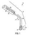
- FIG. 1is a perspective view of one embodiment of a guide device in accordance with the present invention.
- FIG. 2Ais an enlarged side view of the guide member on the guide device shown in FIG. 1 ;
- FIG. 2Bis an enlarged front view of the guide member on the guide device shown in FIG. 1 ;
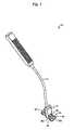
- FIG. 3is a perspective view of the guide device of FIG. 1 coupled to a pair of screw bores in a spinal fixation plate;
- FIG. 4is an enlarged perspective view of the spinal fixation plate of FIG. 3 ;
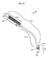
- FIG. 5Ais a perspective view of another embodiment of a guide device according to the present invention.
- FIG. 5Bis a side perspective view of the guide member of the guide device shown in FIG. 5A ;
- FIG. 5Cis a cross-sectional view of the guide member shown in FIG. 5B ;
- FIG. 5Dis a top view of the guide member shown in FIG. 5B ;
- FIG. 6Ais a bottom view of a portion of a spinal fixation plate having another embodiment of a guide device coupled thereto in accordance with the present invention
- FIG. 6Bis perspective side view of the guide device and spinal fixation plate of FIG. 6A ;
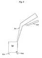
- FIG. 7is a side view illustration of portion of another embodiment of a guide device in accordance with the present invention.
- FIG. 8is a side view illustration of a guide device having a pivotable alignment mechanism in accordance with another embodiment the present invention.
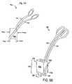
- FIG. 9Ais a side view illustration of yet another embodiment of a guide device in accordance with the present invention.
- FIG. 9Bis a perspective view illustration of the guide device of FIG. 9A ;
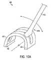
- FIG. 10Ais an enlarged perspective side view of a portion of a guide device having support member coupled to an elongate shaft in accordance with another embodiment of the present invention.
- FIG. 10Bis a perspective side view illustration of the guide device of FIG. 10A coupled to a spinal fixation plate.
- FIG. 10Cis a perspective front view of a portion of the guide device and spinal fixation plate shown in FIG. 10B .
- the present inventionprovides a guide device that is useful during spinal surgery to facilitate implantation of a spinal fixation element, such as a spinal fixation plate.
- the deviceincludes an elongate shaft having a proximal end and a distal end that is coupled to a guide member.
- the guide memberincludes at least one pathway extending therethrough for receiving a tool.
- At least one alignment elementis positioned distal of the guide member, and it is adapted to interact with a spinal fixation element to position the at least one pathway in the guide member in alignment with at least one corresponding bore formed in the spinal fixation element, thereby providing a fixed entry angle for tools being inserted therethrough.
- the guide devicecan be used to drill, awl, tap, and insert tools, devices, and/or implants, such as bone screws, into the vertebral bodies to attach the spinal fixation element thereto.
- the guide deviceis particularly advantageous in that it provides a more time efficient and simplified surgical procedure, eliminating several unnecessary steps and instruments typically required to implant a spinal fixation element, such as a spinal fixation plate.
- the alignment element(s)does not rigidly attach to the spinal fixation element, thus allowing the guide member to advantageously be quickly and easily positioned and aligned with a spinal fixation element.
- the guide membercan also be advantageously configured to have a relatively small profile, unlike some prior art devices.
- the guide membercan include one or more alignment tabs, at least one of which can interact with a graft window formed in a spinal fixation element.
- the guide membercan be positioned over and aligned with the spinal fixation element without impinging on any adjacent soft tissues that may be located at the lateral edges of the spinal fixation element.
- the guide membercan include one or more windows formed therein for facilitating visual access of the surgical site and of tools or devices being introduced through the guide member.
- FIG. 1illustrates one embodiment of a guide device 10 in accordance with the present invention.
- the device 10generally includes an elongate shaft 12 having a proximal portion 12 a , and a distal portion 12 b that is coupled to a guide member 18 .
- the guide member 18includes first and second pathways in the form of lumens 20 , 22 formed therein and extending therethrough.
- the lumens 20 , 22are adapted to be aligned with corresponding thru bores formed in a spinal fixation element when the guide member 18 is coupled to a spinal fixation element.
- the guide membercan also include features for facilitating alignment of the guide member 18 with a spinal fixation element, as will be discussed in more detail below.
- the elongate shaft 12 of device 10can have a variety of configurations, shapes and sizes, but in an exemplary embodiment, the proximal portion 12 a is adapted to extend out of a patient's body, while the distal portion 12 b is coupled to the guide member 18 , which can be inserted into a surgical incision within in the patient's body.
- the distal end 12 bcan optionally be adapted to retract tissue, as is described in related U.S. patent application Ser. No. 10/609,123, which is incorporated herein by reference in its entirety.
- the proximal and distal portions 12 a , 12 bcan be fixedly attached to, removably mated to, or integrally formed with one another, but preferably a portion of the shaft 12 is disposed at an angle ⁇ such that the proximal portion 12 a is offset from the guide member 18 to facilitate visual and physical access to the surgical site. While the angle ⁇ in the shaft 12 can vary, in an exemplary embodiment, the angle ⁇ is in the range of about 110° to 160°, and more preferably it is in the range of about 125° to 145°.
- the elongate member 12can include two or more bends to facilitate visual access to the surgical site and/or to facilitate positioning of the device 10 in the patient's body.
- the proximal portion 12 acan optionally be adjustably movable with respect to the distal portion 12 b to allow the surgeon to adjust the angle and/or position of the proximal portion 12 a with respect to the distal portion 12 b.
- the proximal portion 12 a of elongate member 12can have a variety of configurations, but it preferably includes a handle 28 formed thereon or mated thereto.
- the handle 28can have virtually any shape and size, and it can optionally include a gripping surface 30 , such as a knurled surface, ridges, or grooves, to further facilitate grasping of the device 10 .
- the proximal portion 12 a of the elongate member 12can include a clamp member (not shown) formed thereon or mated thereto that is effective to mate the device 10 to a surgical retractor, such as, for example a Bookwalter retractor.
- the surgical retractorcan contain a post or surface for attaching to a Bookwalter retractor having a clamp.
- a person skilled in the artwill appreciate that a variety of clamp members and/or other mating techniques can be used to mate the device 10 to a retractor or other type of support member.
- the distal portion 12 b of the elongate member 12can also have a variety of shapes and sizes, but it should be adapted to couple to the guide member 18 .
- the distal portion 12 bis fixedly attached to or integrally formed with the guide member 18 at a location that is substantially between, but offset from the center axis of the first and second lumens 20 , 22 in the guide member 18 .
- This offset designwill provide better visual and physical access to the guide member 18 , since the elongate shaft 12 extends from a side of the guide member 18 .
- the distal portion 12 b of the elongate member 12can be removably mated to the guide member 18 , and/or it can be mated to virtually any portion of the guide member 18 .
- the guide member 18which is shown in more detail in FIGS. 2A and 2B , can also have a variety of configurations, shapes, and sizes, but in an exemplary embodiment the guide member 18 preferably has a substantially rectangular, elongate shape. For reference purposes, each side of the guide member 18 will be referred to in accordance with its location when the guide member 18 is in use.
- the guide member 18includes opposed superior and inferior sides 18 a , 18 b , and opposed first and second transverse sides 18 c , 18 d that extend between the opposed superior and inferior sides 18 a , 18 b .
- the transverse sides 18 c , 18 dpreferably have a width w 1 that is less than a width w 2 of the superior and inferior sides 18 a , 18 b .
- the guide member 18should, however, have a shape and size that results in the alignment of the lumens 20 , 22 with corresponding bores formed in a spinal fixation element that is coupled to the device 10 , as will be discussed below.
- the guide member 18also includes at least one pathway formed therein for receiving a tool, such as an awl, a drill bit, a fastener, or a driver device. While the at least one pathway can have a variety of configurations, FIGS. 1-2B illustrate first and second lumens 20 , 22 formed in and extending through the guide member 18 . The lumens 20 , 22 are spaced apart from one another such that each lumen 20 , 22 is positioned adjacent to a transverse side 18 c , 18 d of the guide member 18 .
- the position or angle of the lumens 20 , 22 with respect to one anothercan vary depending on the intended use, however the lumens 20 , 22 should be adapted to align with corresponding thru bores formed in a spinal fixation element to provide a fixed entry angle for a device being inserted therethrough.
- the guide member 18is adapted to interact with a spinal fixation element such that the lumens 20 , 22 , in the guide member 18 are aligned with corresponding bores formed in the spinal fixation element.
- a distal end surface 32 of the guide member 18can be adapted to rest against a spinal fixation element.
- the distal end surface 32 of the guide member 18has a shape that is adapted to match the contour (in the transverse direction) of a spinal fixation element, such as a spinal fixation plate.
- the distal end surface 32 of the guide member 18can have a substantially concave shape that is adapted to rest against a spinal fixation plate having a convex surface.
- Alignment between the guide member 18 and a spinal fixation elementcan also be achieved using one or more alignment elements formed on the guide member 18 .
- Each alignment elementcan have a variety of configurations, and they can be adapted to interact with various features on a spinal fixation element.
- the alignment element(s)can be configured to non-rigidly or rigidly couple to the spinal fixation element, and/or the alignment element(s) can interact with the spinal fixation element to either prevent rotation or to allow some rotation of the guide member 18 with respect to the spinal fixation element.
- guide member 18includes opposed first and second alignment tabs 24 , 26 extending distally therefrom, preferably such that the tabs 24 , 26 are substantially parallel to one another.
- the tabs 24 , 26are effective to interact with edges formed on a spinal fixation element, such as a spinal fixation plate, to align the lumens 20 , 22 in the guide member 18 with corresponding bores in the spinal fixation element.
- the shape, size, and position of each tab 24 , 26can vary, and they can be adapted to match the contour of particular portions of a spinal fixation element.
- the tabs 24 , 26have a substantially rectangular shape and they are positioned on and they extend distally from the opposed superior and inferior surfaces 18 a , 18 b of the guide member 18 at a location that is substantially between the lumens 20 , 22 .
- one tab 24 , 26can be positioned against a superior or inferior edge of a spinal fixation element, and the other tab 24 , 26 can be positioned on an edge of a graft window formed in the spinal fixation element, as will be discussed in more detail below.
- the location of the tabs on the superior and inferior surfaces 18 a , 18 b of the guide member 18is particularly advantageous in that it prevents the tabs from impinging on any adjacent soft tissues that may be located at the lateral edges of the spinal fixation element when the guide member 18 is coupled to a spinal fixation element.
- the tabs 24 , 26preferably do not extend into any cut-out portions formed in the spinal fixation element, or otherwise include an engagement feature for engaging the spinal fixation element, the tabs 24 , 26 can provide a clearance fit therebetween to minimize rotation of the guide member 18 with respect to the spinal fixation element when the tabs 24 , 26 are aligned therewith. More preferably, the tabs 24 , 26 can be adapted to provide a sliding interference fit with the spinal fixation element such that the tabs 24 , 26 are effective to retain the spinal fixation element therebetween. This can be achieved by providing a distance d t ( FIG.
- the guide device 10can be used to manipulate the spinal fixation element. Subsequently, some force may likewise be required to remove the guide device 10 from the spinal fixation element. This is advantageous in that the tabs 24 , 26 allow the guide member 18 to be quickly and easily positioned against, and subsequently removed from, the spinal fixation element.
- the tabs 24 , 26can be configured to engage and/or fixedly interact with the spinal fixation element.
- the tabscan be formed from a compliant material that allows the tabs 24 , 26 to flex to engage the spinal fixation element.
- the tabs 24 , 26can be adapted to extend into corresponding slots formed in the spinal fixation element, and/or they can provide a snap-fit engagement with the spinal fixation element.
- each tab 24 , 26can include a ridge formed thereon that is adapted to fit within a corresponding groove formed in an edge of the spinal fixation element or formed within a slot in the spinal fixation element. In this configuration, the tabs 24 , 26 should be slightly flexible to allow the tabs to engage and disengage the spinal fixation element. Additional techniques for aligning the guide member 18 with a spinal fixation element will be discussed in more detail below.
- FIG. 3illustrates device 10 mated to an exemplary embodiment of a spinal fixation element, i.e., spinal fixation plate 50 , which is disclosed in more detail in U.S. patent application Ser. No. 10/664,238, filed Sep. 17, 2003 and entitled “Bone Fixation Plates.”
- the spinal fixation plate 50which is shown separately in FIG. 4 , includes four outer edges: a superior edge 50 a , an inferior edge 50 b , and first and second opposed lateral sides 50 c , 50 d . As shown in FIG.
- a first pair of screw bores 52 a , 52 bis formed in a superior portion 52 of the spinal fixation plate 50
- a second pair of screw bores 54 a , 54 bis formed a mid-portion 54 of the spinal fixation plate 50
- a third pair of screw bores 56 a , 56 bis formed an inferior portion 56 of the spinal fixation plate 50 .
- the spinal fixation plate 50also includes a first graft window 58 formed therein between the first and second pair of screw bores 52 a , 52 b , 54 a , 54 b , and a second graft window 60 formed therein between the second and third pair of screw bores 54 a , 54 b , 56 a , 56 b .
- the graft windows 58 , 60are configured such that the distance d 1 between the superior edge 50 a of the spinal fixation plate 50 and a superior edge 58 a of the first graft window 58 is equal to the distance d 2 between an inferior edge 58 b of the first graft window 58 and a superior edge 60 a of the second graft window 60 , which is equal to the distance d 3 between an inferior edge 60 b of the second graft window 60 and the inferior edge 50 b of the spinal fixation plate 50 .
- each distance d 1 , d 2 , d 3 between the edges of the plate 50is preferably greater than the distance d t ( FIG. 2A ) between the tabs 24 , 26 such that the tabs 24 , 26 provide a sliding interference fit with the plate 50 .
- the opposed alignment tabs 24 , 26 on the guide member 18can be aligned with any one of the three pairs of screw bores 52 a , 52 b , 54 a , 54 b , 56 a , 56 b formed in the spinal fixation plate 50 .
- FIG. 3illustrates the guide member 18 aligned with the second pair of screw bores 54 a , 54 b formed in the mid-portion 54 of the spinal fixation plate 50 .
- tab 24is positioned adjacent to superior edge 60 a of the second graft window 60
- tab 26(not shown) is positioned adjacent to the inferior edge 58 b of the first graft window 58 .
- FIGS. 5A-5Dillustrate another embodiment of a guide device 510 in accordance with the present invention.
- the guide device 510is similar to guide device 10 in that it includes an elongate shaft 512 having a proximal portion 512 a , and a distal portion 512 b that is coupled to a guide member 518 .
- the guide member 518does not include two separate lumens extending therethrough, but rather it includes first and second pathways 520 , 522 formed within a single lumen extending therethrough between proximal and distal ends 519 a , 519 b thereof. As shown, each pathway 520 , 522 is defined by a substantially semi-cylindrical or C-shaped sidewall.
- each pathway 520 , 522is configured to receive and guide a tool toward a spinal fixation element, such as a spinal fixation plate, positioned in relation to the guide member 518 .
- a spinal fixation elementsuch as a spinal fixation plate
- the pathways 520 , 522can be only partially in communication with one another, or they can be separated from one another, and they can have a variety of other shapes and sizes.
- the first and second pathwayscan be positioned at an angle with respect to one another. For example, a central axis of the first pathway can be non-parallel to a central axis of the second pathway, such that the central axis of the first pathway and the central axis of the second pathway converge relative to one another.
- the guide member 518can also optionally include one or more cut-out portions or windows formed therein to facilitate visual access to a spinal fixation element coupled to the guide device 510 .
- the cut-out portionscan be formed anywhere in the guide member 518 , but in an exemplary embodiment a first cut-out portion 528 is formed in a superior sidewall 518 a of the guide member 518 between the first and second pathways 520 , 522 , and a second, opposed cut-out portion 529 is formed in the inferior sidewall 518 b of the guide member 518 .
- the first cut-out portion 528extends from the proximal end 519 a of the guide member 518 to the distal end 519 b of the guide member 518 , such that the superior sidewall 518 a of the guide member 518 is separated into two sides.
- the second cut-out portion 529extends proximally from the distal end 519 b of the guide member 518 through a substantial portion of the guide member 518 .
- the second cut-out portion 529terminates just distal to the proximal end 519 a of the guide member 518 a to allow the lateral sidewalls 519 c , 519 d that define the pathways 520 , 522 to remain coupled to one another, and to allow the elongate member 512 to mate to the guide member 518 at a substantial mid-portion thereof.
- the cut-out portions 528 , 529are particularly advantageous in that they provide the surgeon with improved visual access to a spinal fixation element positioned in relation to the guide member 518 , as well as to the tools and devices used in connection with the guide device 510 . At least one of the cut-out portions 528 , 529 can also avoid interference by the guide member 518 with a temporary fixation pin that may be disposed through the spinal fixation element to temporarily attach the fixation element to bone. Since temporary fixation pins are typically only placed on opposed ends of a fixation element, such as a spinal fixation plate, the cut-out portion 528 , 529 that is positioned adjacent to an end of the fixation element can receive at least a portion of a temporary fixation pin therebetween.
- the shape, size, and location of each cut-out portion 528 , 529can vary, and that the guide member 518 can include a variety of other cut-out portions and/or windows formed therein.
- guide device 10 ′is preferably adapted to couple to or be juxtaposition on a spinal fixation element, and more preferably to a spinal fixation plate.
- the guide member 518can include at least one mating element or alignment mechanism formed thereon for engaging or otherwise coupling to a spinal fixation element.
- the distal end 519 b of the guide member 518has a shape that is adapted to match the shape of a spinal fixation plate, and in particular the distal-most end portion 519 c is substantially concave to seat a convex surface of the plate.
- the guide member 518also includes distally-extending tabs 524 , 526 formed on each sidewall 518 c , 518 d that are effective to seat a spinal fixation element therebetween.
- the tabs 524 , 526each preferably have a substantially concave inner surface such that they match the contour of a substantially convex outer surface formed around opposed thru bores formed in a spinal fixation element. This allows the tabs 524 , 526 to rest against and/or engage opposed outer surfaces of the spinal fixation element.
- the tabs 524 , 526preferably do not, however, extend into any cut-out portions formed in the spinal fixation element, but they can be adapted to provide a sliding interference fit with outer edges of the spinal fixation element to engage the fixation element, as discussed above with respect to guide device 10 .
- the guide member 518can include any number of tabs formed on any sidewall thereof, and that the guide member 518 can include a variety of other mating elements, including those previously described with respect to guide device 10 .
- FIGS. 6A-6Billustrate a portion of another embodiment of a guide device 610 in accordance with the present invention.
- the device 610is similar to guide devices 10 and 510 , however the guide member 618 includes first and second barrels 619 , 621 having lumens 620 , 622 extending therethrough, respectively.
- the use of separate barrels 619 , 621 , rather than a housing,is particularly advantageous in that it provides improved visual access to a spinal fixation element coupled to the guide device 610 .
- the barrels 619 , 621can also be advantageously configured to have an adjustable length, and/or an adjustable angle.
- the barrels 619 , 621can also optionally be removable to allow barrels having different lengths to be selected based on the intended.
- the guide member 618 show in FIGS. 6A-6Balso includes tabs 624 , 626 formed thereon to facilitate alignment of the guide member 618 with a spinal fixation element.
- the tabs 624 , 626are similar to tabs 524 and 526 on guide member 518 of guide device 510 in that they extend distally from opposed transverse sides 618 c , 618 d of the guide member 610 such that the lumens 620 , 622 in the guide member 618 are positioned between the tabs 624 , 626 .
- the tabs 624 , 626will align with the opposed lateral side edges 50 c ′, 50 d ′ of a spinal fixation plate 50 ′, as show in FIG. 6B .
- each tab 624 , 626has a shape that conforms to a shape of the lateral edges 50 c ′, 50 d ′ of the spinal fixation plate 50 ′ adjacent to screw bores 52 a ′, 52 b ′ formed in the spinal fixation plate 50 ′.
- the tabs 624 , 626have a concave shape, or at least a concave inner surface, that matches the convex shape of the spinal fixation plate 50 ′ along the lateral edges 50 c ′, 50 d ′ of the spinal fixation plate 50 adjacent to the screw bores 52 a ′, 52 b ′ formed in the spinal fixation plate 50 ′.
- the guide member 618can include a mating element, such as a protrusion or pin member 40 , that extends from a distal surface thereof.
- the pin member 40can be formed at any location on the guide member 618 , but it is preferably at a location that is substantially between the first and second lumens 620 , 622 .
- the pin member 40is adapted to extend into a corresponding detent or bore 62 formed in the spinal fixation plate 50 ′.
- the pin member 40can optionally extend at an angle to further facilitate grasping the spinal fixation plate 50 ′.
- the pin member 40is adapted to prevent rotation between the guide member 618 and the spinal fixation plate 50 ′ to provide stability to the connection.
- mating elements with non-symmetrical shapessuch as a pin with a non-circular cross section (e.g., rectangular, oval, triangular, irregular), a multi-pronged mating element, or a tongue-and-groove combination, can prevent or reduce the tendency of the device 10 ′ to pivot with respect to the spinal fixation plate 50 ′.
- the guide device 710can include a guide member 718 having a fixed tab 724 and an opposed deflecting tab 720 that is adapted to provide a friction fit between a spinal fixation element and the guide member 718 .
- the deflecting tab 720can include a fixed tab portion 726 positioned adjacent thereto to prevent the deflecting tab 720 from accidentally breaking.
- the tabs 720 , 724 , 726can be formed on opposed transverse sides of the guide member, or alternatively they can be formed on superior and inferior sides of the guide member.
- FIG. 8illustrates yet another embodiment of a guide device 810 in which the guide member 818 includes a fixed tab 824 and a pivoting tab 826 .
- the pivoting tab 826can be coupled to a lever 814 that is formed on the handle of the shaft 812 for controlling the pivoting motion of the tab 826 .
- a cable or similar elementcan extend between the lever 814 and the tab 826 for moving the tab 826 between open and closed positions.
- the pivoting tab 826 and the fixed tab 824can be formed on opposed transverse sides of the guide member 818 , or alternatively they can be formed on superior and inferior sides of the guide member 818 .
- FIGS. 9A and 9Billustrate a similar embodiment of a guide member 918 having a pivoting alignment mechanism 926 .
- the shaftis in the form of a first handle member 912 , which is preferably fixed with respect to the guide member 918 , and a second handle member 914 that is pivotally coupled to the guide member 918 .
- An alignment tab 926is formed on the distal portion of the second handle member 914 , such that movement of the second handle member 914 is effective to move the alignment tab 926 between open and closed positions.
- the tab 926in combination with an opposed fixed tab 924 , is effective to engage a spinal fixation element therebetween when the alignment tab 926 is in the closed position. While FIG.
- FIGBillustrates tabs 924 , 926 formed on superior and inferior sides 918 a , 918 b of the guide member 918
- the tabs 924 , 926can optionally be formed on opposed transverse sides 918 c , 918 d of the guide member for engaging lateral edges of a spinal fixation element.
- a person skilled in the artwill appreciate that a variety of other techniques can be employed for providing at least one pivotable alignment mechanism, and in general for aligning the guide member with a spinal fixation element.
- the present inventionalso provides a guide device that includes a variable angle guide member, as shown in FIGS. 10A-10B .
- the guide device 400is similar to guide device 10 described with respect to FIGS. 1-2B .
- the guide member 418does not include alignment elements that are formed thereon and extending distally therefrom. While the alignment elements are positioned distal of the guide member 418 , they are formed on a support member 450 that allows the angle of the guide member 418 to be adjusted.
- the guide device 400includes an elongate shaft 412 having a proximal, handle end 412 a and a distal end 412 b .
- the distal end 412 b of the shaft 412is slidably coupled to a support member 450 which is adapted to couple to a spinal fixation element, e.g., spinal fixation plate 50 .
- a spinal fixation elemente.g., spinal fixation plate 50 .
- a variety of techniquescan be used to mate the distal end 412 b of the shaft 412 to the support member 450 , but it should be adjustable between several fixation positions.
- the proximal, handle end 412 a of the shaftincludes first and second handles 413 a , 413 b that are effective to control movement of the shaft 412 with respect to the support member 450 .
- One or both handles 413 a , 413 bcan be movable, but preferably handle 413 a is fixed, and handle 413 b is a trigger that is pivotable such that movement of trigger 413 b is effective to engage and disengage the support member 450 .
- An engagement mechanismsuch as a brake 415 , can be coupled to the distal end 412 b of the shaft for engaging the support member 450 .
- actuation of the trigger 413 bis preferably effective to release the brake 415 to allow the shaft 412 to be slidably movable with respect to the support member 450 .
- the trigger 413 bcan then be released to cause the brake 415 to re-engage the support member 450 .
- the handles 413 a , 413 bcan also include a ratchet mechanism (not shown) or other engagement mechanism for temporarily maintaining the position of the first and second handles 413 a , 413 b with respect to one another.
- a ratchet mechanismnot shown
- a person skilled in the artwill appreciate that a variety of other techniques can be used to effect and/or control movement of the shaft 412 and/or the guide member 418 with respect to the support member 450 .
- the distal end 412 bin addition to being coupled to a support member 450 , is coupled to a guide member 418 .
- the guide member 418includes first and second barrels 418 a , 418 b having lumens extending therethrough for receiving a tool.
- Each barrel 418 a , 418 bis mated to one another and to the distal end 412 b of the shaft 412 by a connection member 420 .
- connection member 420allows the barrel 412 a , 412 b to be positioned on opposed sides of the support member 450 , and to extend distal of the support member 450 such that the barrels 418 a , 418 b can be positioned adjacent to a spinal fixation element that is coupled to the support member 450 .
- An exemplary support member 450is shown in more detail in FIG. 10A , and it can have a variety of configurations.
- the support member 450is, however, preferably arch-shaped to allow the angle of the shaft 412 , and thus the angle of the guide member 418 , to be adjusted as desired.
- the support member 450should also be adapted to engage opposed edges formed on a spinal fixation element, and in particular to engage a superior or inferior edge and/or an edge of a graft window.
- the support member 450includes a substantially concave groove 452 , 454 formed on an inner surface of each end of the support member 450 .
- the opposed grooves 452 , 454are configured to fit around opposed edges of a spinal fixation element.
- the support member 450should rigidly connect to or at least temporarily engage the spinal fixation element to prevent removal of the support member 450 during adjustment of the guide member 418 .
- the guide device of the present inventioncan also be provided as part of a spinal fixation kit that includes a spinal fixation element having at least one thru bore formed therein for receiving a fastening element that is effective to mate the spinal fixation element to at least one vertebrae.
- the spinal fixation elemente.g., a spinal fixation plate
- the kitcan include additional devices, tools, and/or implants, such as fastening devices, bone preparation devices, etc.
- the guide devices of the present inventioncan be used to implant a variety of spinal fixation elements, and once the spinal fixation element is properly positioned against the spine and the guide device is aligned with the spinal fixation element, implants, tools, and/or devices, such as, for example, a drill, awl, tap, or bone screw, can be passed through the each pathway in the guide member to prepare the vertebrae and/or to couple a spinal implant to the vertebrae.
- implants, tools, and/or devicessuch as, for example, a drill, awl, tap, or bone screw
Landscapes
- Health & Medical Sciences (AREA)
- Surgery (AREA)
- Orthopedic Medicine & Surgery (AREA)
- Life Sciences & Earth Sciences (AREA)
- Biomedical Technology (AREA)
- Molecular Biology (AREA)
- Oral & Maxillofacial Surgery (AREA)
- Engineering & Computer Science (AREA)
- Dentistry (AREA)
- Heart & Thoracic Surgery (AREA)
- Medical Informatics (AREA)
- Nuclear Medicine, Radiotherapy & Molecular Imaging (AREA)
- Animal Behavior & Ethology (AREA)
- General Health & Medical Sciences (AREA)
- Public Health (AREA)
- Veterinary Medicine (AREA)
- Surgical Instruments (AREA)
- Prostheses (AREA)
Abstract
Description
Claims (18)
Priority Applications (1)
| Application Number | Priority Date | Filing Date | Title |
|---|---|---|---|
| US12/838,013US8394107B2 (en) | 2003-04-09 | 2010-07-16 | Guide for spinal tools, implants, and devices |
Applications Claiming Priority (5)
| Application Number | Priority Date | Filing Date | Title |
|---|---|---|---|
| US10/409,958US7416553B2 (en) | 2003-04-09 | 2003-04-09 | Drill guide and plate inserter |
| US10/609,123US7909829B2 (en) | 2003-06-27 | 2003-06-27 | Tissue retractor and drill guide |
| US10/664,575US7935123B2 (en) | 2003-04-09 | 2003-09-17 | Drill guide with alignment feature |
| US10/776,414US7776047B2 (en) | 2003-04-09 | 2004-02-11 | Guide for spinal tools, implants, and devices |
| US12/838,013US8394107B2 (en) | 2003-04-09 | 2010-07-16 | Guide for spinal tools, implants, and devices |
Related Parent Applications (2)
| Application Number | Title | Priority Date | Filing Date |
|---|---|---|---|
| US10/609,123Continuation-In-PartUS7909829B2 (en) | 2003-04-09 | 2003-06-27 | Tissue retractor and drill guide |
| US10/776,414ContinuationUS7776047B2 (en) | 2003-04-09 | 2004-02-11 | Guide for spinal tools, implants, and devices |
Related Child Applications (1)
| Application Number | Title | Priority Date | Filing Date |
|---|---|---|---|
| US10/664,575Continuation-In-PartUS7935123B2 (en) | 2003-04-09 | 2003-09-17 | Drill guide with alignment feature |
Publications (2)
| Publication Number | Publication Date |
|---|---|
| US20110015685A1 US20110015685A1 (en) | 2011-01-20 |
| US8394107B2true US8394107B2 (en) | 2013-03-12 |
Family
ID=46300838
Family Applications (2)
| Application Number | Title | Priority Date | Filing Date |
|---|---|---|---|
| US10/776,414Expired - LifetimeUS7776047B2 (en) | 2003-04-09 | 2004-02-11 | Guide for spinal tools, implants, and devices |
| US12/838,013Expired - Fee RelatedUS8394107B2 (en) | 2003-04-09 | 2010-07-16 | Guide for spinal tools, implants, and devices |
Family Applications Before (1)
| Application Number | Title | Priority Date | Filing Date |
|---|---|---|---|
| US10/776,414Expired - LifetimeUS7776047B2 (en) | 2003-04-09 | 2004-02-11 | Guide for spinal tools, implants, and devices |
Country Status (1)
| Country | Link |
|---|---|
| US (2) | US7776047B2 (en) |
Cited By (38)
| Publication number | Priority date | Publication date | Assignee | Title |
|---|---|---|---|---|
| US20110218575A1 (en)* | 2006-04-21 | 2011-09-08 | Interventional Spine, Inc. | Method and apparatus for spinal fixation |
| US20120265021A1 (en)* | 2011-04-13 | 2012-10-18 | Nottmeier Eric W | Anterior Cervical Retractor System |
| WO2015184018A1 (en)* | 2014-05-28 | 2015-12-03 | Providence Medical Technology, Inc. | Lateral mass fixation system |
| US9204906B2 (en) | 2009-10-22 | 2015-12-08 | Nuvasive, Inc. | Posterior cervical fusion system and techniques |
| US9622791B2 (en) | 2008-06-06 | 2017-04-18 | Providence Medical Technology, Inc. | Vertebral joint implants and delivery tools |
| US9622874B2 (en) | 2008-06-06 | 2017-04-18 | Providence Medical Technology, Inc. | Cervical distraction/implant delivery device |
| US9622873B2 (en) | 2006-12-29 | 2017-04-18 | Providence Medical Technology, Inc. | Cervical distraction method |
| US9883951B2 (en) | 2012-08-30 | 2018-02-06 | Interventional Spine, Inc. | Artificial disc |
| US9937055B1 (en) | 2016-11-28 | 2018-04-10 | Spine Wave, Inc. | Scoring implant trial and implant inserter for spinal fusion system |
| US9968464B2 (en) | 2014-01-17 | 2018-05-15 | Spine Wave, Inc. | Spinal fusion system |
| US10039649B2 (en) | 2008-06-06 | 2018-08-07 | Providence Medical Technology, Inc. | Composite spinal facet implant with textured surfaces |
| US10098674B2 (en) | 2009-10-22 | 2018-10-16 | Nuvasive, Inc. | System and method for posterior cervical fusion |
| US10143499B2 (en) | 2013-10-09 | 2018-12-04 | Stryker European Holdings I, Llc | Pivoting vertebral plate |
| US10149673B2 (en) | 2008-06-06 | 2018-12-11 | Providence Medical Technology, Inc. | Facet joint implants and delivery tools |
| US10172721B2 (en) | 2008-06-06 | 2019-01-08 | Providence Technology, Inc. | Spinal facet cage implant |
| USD841165S1 (en) | 2015-10-13 | 2019-02-19 | Providence Medical Technology, Inc. | Cervical cage |
| US10531904B2 (en) | 2014-04-30 | 2020-01-14 | Eric D. Kolb | Bone screw with apertures |
| US10631884B2 (en) | 2017-06-05 | 2020-04-28 | Conmed Corporation | Multi-barrel drill guide |
| US10682243B2 (en) | 2015-10-13 | 2020-06-16 | Providence Medical Technology, Inc. | Spinal joint implant delivery device and system |
| USD887552S1 (en) | 2016-07-01 | 2020-06-16 | Providence Medical Technology, Inc. | Cervical cage |
| US10888434B2 (en) | 2017-10-05 | 2021-01-12 | Spine Wave, Inc. | Modular scoring trial for anterior cervical cage |
| USD911525S1 (en) | 2019-06-21 | 2021-02-23 | Providence Medical Technology, Inc. | Spinal cage |
| USRE48501E1 (en) | 2012-10-23 | 2021-04-06 | Providence Medical Technology, Inc. | Cage spinal implant |
| US11065039B2 (en) | 2016-06-28 | 2021-07-20 | Providence Medical Technology, Inc. | Spinal implant and methods of using the same |
| USD933230S1 (en) | 2019-04-15 | 2021-10-12 | Providence Medical Technology, Inc. | Cervical cage |
| US11224524B2 (en) | 2015-02-02 | 2022-01-18 | Spinal Elements, Inc. | Interbody implant inserter |
| US11224521B2 (en) | 2008-06-06 | 2022-01-18 | Providence Medical Technology, Inc. | Cervical distraction/implant delivery device |
| USD945621S1 (en) | 2020-02-27 | 2022-03-08 | Providence Medical Technology, Inc. | Spinal cage |
| US11273058B2 (en) | 2019-05-07 | 2022-03-15 | Spinal Elements, Inc. | Cervical plate and inserter |
| US11272964B2 (en) | 2008-06-06 | 2022-03-15 | Providence Medical Technology, Inc. | Vertebral joint implants and delivery tools |
| US11351038B2 (en) | 2012-02-17 | 2022-06-07 | Spinal Elements, Inc. | Interbody fusion device |
| US11471173B2 (en) | 2017-06-05 | 2022-10-18 | Conmed Corporation | Multi-barrel drill guide and anchor deployment assembly |
| US11559408B2 (en) | 2008-01-09 | 2023-01-24 | Providence Medical Technology, Inc. | Methods and apparatus for accessing and treating the facet joint |
| US11648128B2 (en) | 2018-01-04 | 2023-05-16 | Providence Medical Technology, Inc. | Facet screw and delivery device |
| US11871968B2 (en) | 2017-05-19 | 2024-01-16 | Providence Medical Technology, Inc. | Spinal fixation access and delivery system |
| US12004781B2 (en) | 2014-05-27 | 2024-06-11 | Providence Medical Technology, Inc. | Lateral mass fixation implant |
| US12144513B2 (en) | 2018-09-21 | 2024-11-19 | Providence Medical Technology, Inc. | Vertebral joint access and decortication devices and methods of using |
| USD1098433S1 (en) | 2023-12-28 | 2025-10-14 | Providence Medical Technology, Inc. | Spinal cage |
Families Citing this family (97)
| Publication number | Priority date | Publication date | Assignee | Title |
|---|---|---|---|---|
| US8172885B2 (en) | 2003-02-05 | 2012-05-08 | Pioneer Surgical Technology, Inc. | Bone plate system |
| US7776047B2 (en) | 2003-04-09 | 2010-08-17 | Depuy Spine, Inc. | Guide for spinal tools, implants, and devices |
| US7909829B2 (en) | 2003-06-27 | 2011-03-22 | Depuy Spine, Inc. | Tissue retractor and drill guide |
| US7909848B2 (en)* | 2003-06-27 | 2011-03-22 | Depuy Spine, Inc. | Tissue retractor and guide device |
| US7686810B2 (en)* | 2003-08-29 | 2010-03-30 | Hs West Investments, Llc | Suture separation and organization devices for use with graft tensioning device |
| US8900277B2 (en) | 2004-02-26 | 2014-12-02 | Pioneer Surgical Technology, Inc. | Bone plate system |
| US7740649B2 (en) | 2004-02-26 | 2010-06-22 | Pioneer Surgical Technology, Inc. | Bone plate system and methods |
| US7488327B2 (en)* | 2004-04-12 | 2009-02-10 | Synthes (U.S.A.) | Free hand drill guide |
| US20060058796A1 (en)* | 2004-09-14 | 2006-03-16 | Hartdegen Vernon R | Compression brace |
| US7621916B2 (en)* | 2004-11-18 | 2009-11-24 | Depuy Spine, Inc. | Cervical bone preparation tool and implant guide systems |
| US7166111B2 (en)* | 2004-12-08 | 2007-01-23 | Depuy Spine, Inc. | Spinal plate and drill guide |
| US7931678B2 (en) | 2004-12-08 | 2011-04-26 | Depuy Spine, Inc. | Hybrid spinal plates |
| US7736380B2 (en) | 2004-12-21 | 2010-06-15 | Rhausler, Inc. | Cervical plate system |
| US9848993B2 (en) | 2005-04-12 | 2017-12-26 | Nathan C. Moskowitz | Zero-profile expandable intervertebral spacer devices for distraction and spinal fusion and a universal tool for their placement and expansion |
| US7972363B2 (en) | 2005-04-12 | 2011-07-05 | Moskowitz Ahmnon D | Bi-directional fixating/locking transvertebral body screw/intervertebral cage stand-alone constructs and posterior cervical and lumbar interarticulating joint stapling guns and devices for spinal fusion |
| US7942903B2 (en) | 2005-04-12 | 2011-05-17 | Moskowitz Ahmnon D | Bi-directional fixating transvertebral body screws and posterior cervical and lumbar interarticulating joint calibrated stapling devices for spinal fusion |
| US11903849B2 (en) | 2005-04-12 | 2024-02-20 | Moskowitz Family Llc | Intervertebral implant and tool assembly |
| US7704279B2 (en) | 2005-04-12 | 2010-04-27 | Moskowitz Mosheh T | Bi-directional fixating transvertebral body screws, zero-profile horizontal intervertebral miniplates, expansile intervertebral body fusion devices, and posterior motion-calibrating interarticulating joint stapling device for spinal fusion |
| US9744052B2 (en)* | 2005-04-12 | 2017-08-29 | Nathan C. Moskowitz | Bi-directional fixating/locking transvertebral body screw/intervertebral cage stand-alone constructs |
| US7846188B2 (en) | 2005-04-12 | 2010-12-07 | Moskowitz Nathan C | Bi-directional fixating transvertebral body screws, zero-profile horizontal intervertebral miniplates, total intervertebral body fusion devices, and posterior motion-calibrating interarticulating joint stapling device for spinal fusion |
| US9532821B2 (en) | 2005-04-12 | 2017-01-03 | Nathan C. Moskowitz | Bi-directional fixating/locking transvertebral body screw/intervertebral cage stand-alone constructs with vertical hemi-bracket screw locking mechanism |
| US9119677B2 (en) | 2005-12-09 | 2015-09-01 | DePuy Synthes Products, Inc. | Spinal plate and drill guide |
| US8491593B2 (en)* | 2006-01-17 | 2013-07-23 | Stryker Trauma Gmbh | Targeting device for orthopedic implants |
| EP2208471B1 (en)* | 2006-01-17 | 2011-10-12 | Stryker Trauma GmbH | Medical system and system parts for spatially adjusting an aiming device relative to a body implant |
| US8118810B2 (en)* | 2006-01-17 | 2012-02-21 | Stryker Trauma Gmbh | Targeting device for bone implant |
| US9011441B2 (en)* | 2006-02-17 | 2015-04-21 | Paradigm Spine, L.L.C. | Method and system for performing interspinous space preparation for receiving an implant |
| US7854765B2 (en) | 2006-04-20 | 2010-12-21 | Moskowitz Mosheh T | Electronically controlled artificial intervertebral disc with motor assisted actuation systems |
| US20080132900A1 (en)* | 2006-11-13 | 2008-06-05 | Stryker Trauma Gmbh | Drill alignment assembly for a bone plate using tissue protection sleeves that are fixed in the bone plate |
| US8623019B2 (en) | 2007-07-03 | 2014-01-07 | Pioneer Surgical Technology, Inc. | Bone plate system |
| US8361126B2 (en) | 2007-07-03 | 2013-01-29 | Pioneer Surgical Technology, Inc. | Bone plate system |
| US7922767B2 (en)* | 2007-07-07 | 2011-04-12 | Jmea Corporation | Disk fusion implant |
| US8172854B2 (en)* | 2007-07-19 | 2012-05-08 | Spinal Elements, Inc. | Attachable instrument guide with detachable handle |
| WO2009021144A2 (en)* | 2007-08-07 | 2009-02-12 | Transcorp, Inc. | Device for variably adjusting intervertebral distraction and lordosis |
| US7867263B2 (en)* | 2007-08-07 | 2011-01-11 | Transcorp, Inc. | Implantable bone plate system and related method for spinal repair |
| US8709054B2 (en) | 2007-08-07 | 2014-04-29 | Transcorp, Inc. | Implantable vertebral frame systems and related methods for spinal repair |
| WO2009036360A1 (en)* | 2007-09-13 | 2009-03-19 | Transcorp, Inc. | Device and method for tissue retraction in spinal surgery |
| US8430882B2 (en) | 2007-09-13 | 2013-04-30 | Transcorp, Inc. | Transcorporeal spinal decompression and repair systems and related methods |
| WO2009036367A1 (en) | 2007-09-13 | 2009-03-19 | Transcorp, Inc. | Transcorporeal spinal decompression and repair system and related method |
| US20090088604A1 (en)* | 2007-09-28 | 2009-04-02 | David Lowry | Vertebrally-mounted tissue retractor and method for use in spinal surgery |
| EP2397094B1 (en) | 2007-11-02 | 2013-06-26 | Biomet C.V. | Elbow fracture fixation system |
| EP2227181A1 (en) | 2007-11-27 | 2010-09-15 | Transcorp, Inc. | Methods and systems for repairing an intervertebral disc using a transcorporal approach |
| US8088163B1 (en) | 2008-02-06 | 2012-01-03 | Kleiner Jeffrey B | Tools and methods for spinal fusion |
| DE102008010333A1 (en) | 2008-02-21 | 2009-08-27 | Aesculap Ag | Magazine for receiving at least one bone screw and bone plate with such a magazine |
| US20210378834A1 (en) | 2008-05-22 | 2021-12-09 | Spinal Surgical Strategies, Inc., A Nevada Corporation D/B/A Kleiner Device Labs | Spinal fusion cage system with inserter |
| US20090312801A1 (en)* | 2008-06-16 | 2009-12-17 | Lemoine Jeremy J | Multi-guide plate holder |
| US9107712B2 (en) | 2008-09-15 | 2015-08-18 | Biomet C.V. | Bone plate system for hand fractures and other small bones |
| USD853560S1 (en) | 2008-10-09 | 2019-07-09 | Nuvasive, Inc. | Spinal implant insertion device |
| US8366748B2 (en) | 2008-12-05 | 2013-02-05 | Kleiner Jeffrey | Apparatus and method of spinal implant and fusion |
| US9717403B2 (en) | 2008-12-05 | 2017-08-01 | Jeffrey B. Kleiner | Method and apparatus for performing retro peritoneal dissection |
| US8864654B2 (en) | 2010-04-20 | 2014-10-21 | Jeffrey B. Kleiner | Method and apparatus for performing retro peritoneal dissection |
| US8323292B2 (en)* | 2008-12-15 | 2012-12-04 | Spinecore, Inc. | Adjustable pin drill guide and methods therefor |
| US20100168770A1 (en)* | 2008-12-30 | 2010-07-01 | Richard S. Wilkenfeld | Laparoscopic method for suturing in a body cavity |
| US20100168769A1 (en)* | 2008-12-30 | 2010-07-01 | Richard S. Wilkenfeld | Laparoscopic knot pushing device |
| USD656610S1 (en) | 2009-02-06 | 2012-03-27 | Kleiner Jeffrey B | Spinal distraction instrument |
| US9247943B1 (en) | 2009-02-06 | 2016-02-02 | Kleiner Intellectual Property, Llc | Devices and methods for preparing an intervertebral workspace |
| USD630746S1 (en)* | 2009-03-23 | 2011-01-11 | Karl Storz Gmbh & Co. Kg | Drilling gage |
| EP2419053B1 (en)* | 2009-04-15 | 2015-04-08 | Synthes GmbH | Trial implant assembly |
| USD723682S1 (en) | 2013-05-03 | 2015-03-03 | Spinal Surgical Strategies, Llc | Bone graft delivery tool |
| US10973656B2 (en) | 2009-09-18 | 2021-04-13 | Spinal Surgical Strategies, Inc. | Bone graft delivery system and method for using same |
| US20170238984A1 (en) | 2009-09-18 | 2017-08-24 | Spinal Surgical Strategies, Llc | Bone graft delivery device with positioning handle |
| US9173694B2 (en) | 2009-09-18 | 2015-11-03 | Spinal Surgical Strategies, Llc | Fusion cage with combined biological delivery system |
| US8906028B2 (en) | 2009-09-18 | 2014-12-09 | Spinal Surgical Strategies, Llc | Bone graft delivery device and method of using the same |
| US9186193B2 (en) | 2009-09-18 | 2015-11-17 | Spinal Surgical Strategies, Llc | Fusion cage with combined biological delivery system |
| USD750249S1 (en) | 2014-10-20 | 2016-02-23 | Spinal Surgical Strategies, Llc | Expandable fusion cage |
| US10245159B1 (en) | 2009-09-18 | 2019-04-02 | Spinal Surgical Strategies, Llc | Bone graft delivery system and method for using same |
| US8685031B2 (en) | 2009-09-18 | 2014-04-01 | Spinal Surgical Strategies, Llc | Bone graft delivery system |
| US9060877B2 (en) | 2009-09-18 | 2015-06-23 | Spinal Surgical Strategies, Llc | Fusion cage with combined biological delivery system |
| US9629729B2 (en) | 2009-09-18 | 2017-04-25 | Spinal Surgical Strategies, Llc | Biological delivery system with adaptable fusion cage interface |
| US8551107B2 (en)* | 2009-10-15 | 2013-10-08 | Biomet, C.V. | Bending tool and method for reshaping a bone plate |
| EP2531127A4 (en)* | 2009-11-11 | 2015-04-29 | Alphatec Spine Inc | METHODS AND DEVICES FOR FIXING A PENETRATION POINT ON THE VERTEBRAL COLUMN |
| US8579900B2 (en)* | 2010-01-06 | 2013-11-12 | Chia-Hao Hsu | Minimally invasive skeletal fixation device |
| US9138246B2 (en)* | 2010-02-19 | 2015-09-22 | Arthrex, Inc. | Elbow reconstruction instruments and techniques |
| US8808304B2 (en)* | 2010-04-21 | 2014-08-19 | Globus Medical, Inc | Insertion tool assembly |
| US8419745B2 (en)* | 2010-04-23 | 2013-04-16 | Biomet C.V. | Bone plate bender system |
| US8425569B2 (en) | 2010-05-19 | 2013-04-23 | Transcorp, Inc. | Implantable vertebral frame systems and related methods for spinal repair |
| GB2487331B (en) | 2010-09-27 | 2012-10-24 | Acumed Llc | Instruments having a radiopaque region to facilitate positioning a bone plate on bone |
| US11123117B1 (en) | 2011-11-01 | 2021-09-21 | Nuvasive, Inc. | Surgical fixation system and related methods |
| US9050151B2 (en) | 2012-03-06 | 2015-06-09 | Stryker Trauma Sa | Bone plate and aiming block |
| USD708329S1 (en) | 2012-10-24 | 2014-07-01 | Richard S. Wilkenfeld | Laparoscopic knot pushing device |
| US9155582B2 (en) | 2013-01-30 | 2015-10-13 | DePuy Synthes Products, Inc. | Aiming instrument |
| DE102014102907A1 (en) | 2013-04-15 | 2014-10-16 | Aesculap Ag | Surgical screw magazine |
| US11253299B2 (en) | 2013-10-28 | 2022-02-22 | Jace Medical, Llc | Orthopaedic fixation devices, systems and methods |
| JP6315256B2 (en)* | 2013-12-26 | 2018-04-25 | 住友電装株式会社 | Reactor |
| US9433444B2 (en)* | 2014-01-23 | 2016-09-06 | Warsaw Orthopedic, Inc. | Surgical instrument system and method |
| US9427265B2 (en)* | 2014-01-23 | 2016-08-30 | Warsaw Orthopedic, Inc. | Surgical instrument system and method |
| WO2017008087A1 (en) | 2015-07-06 | 2017-01-12 | Javier Garcia-Bengochea | Methods and devices for surgical access |
| EP3164080A4 (en) | 2014-07-06 | 2018-06-27 | Garcia-Bengochea, Javier | Methods and devices for surgical access |
| WO2016029008A1 (en)* | 2014-08-20 | 2016-02-25 | Jace Medical, Llc | Implant positioning devices and methods |
| US9901457B2 (en) | 2014-10-16 | 2018-02-27 | Jmea Corporation | Coiling implantable prostheses |
| USD797290S1 (en) | 2015-10-19 | 2017-09-12 | Spinal Surgical Strategies, Llc | Bone graft delivery tool |
| US10327787B2 (en) | 2015-12-28 | 2019-06-25 | Nuvasive, Inc | Adjustable depth drill guide |
| US10172630B2 (en)* | 2016-05-19 | 2019-01-08 | Medos International Sarl | Drill guide with adjustable stop |
| JP2018015306A (en)* | 2016-07-28 | 2018-02-01 | 株式会社ニューロデザイン | Drill guide, screw guide system, hole drilling method, and spinal fixation method |
| US10080671B2 (en) | 2016-11-01 | 2018-09-25 | Warsaw Orhtopedic, Inc. | Trial and method for use thereof |
| ES2981770T3 (en)* | 2019-03-05 | 2024-10-10 | Medacta Int Sa | Holding and positioning tool for a spinal polyaxial screw insertion guide |
| US11957394B2 (en) | 2020-02-27 | 2024-04-16 | J.M. Longyear Manufacturing, Llc | Screw caddy |
| US11877779B2 (en) | 2020-03-26 | 2024-01-23 | Xtant Medical Holdings, Inc. | Bone plate system |
Citations (231)
| Publication number | Priority date | Publication date | Assignee | Title |
|---|---|---|---|---|
| US1920821A (en) | 1931-09-22 | 1933-08-01 | Wassenaar Jan Jacob Stephanus | Distraction bone forceps |
| US2466023A (en) | 1945-08-11 | 1949-04-05 | Francis J Griffin | Drill jig |
| US2486303A (en) | 1948-04-29 | 1949-10-25 | Harry Herschel Leiter | Surgical appliance for bone fractures |
| US2494229A (en) | 1946-07-08 | 1950-01-10 | John G Collison | Bone surgery |
| US2695688A (en) | 1950-05-05 | 1954-11-30 | Gen Electric | Screw fastener |
| US2756742A (en) | 1953-08-18 | 1956-07-31 | Barton Foundation | Endotracheal tongue blade with tube guide |
| US3244170A (en) | 1962-11-23 | 1966-04-05 | Robert T Mcelvenny | Compression type bone splint |
| US3463148A (en) | 1966-01-20 | 1969-08-26 | Richards Mfg Co | Bone plate |
| US3552389A (en) | 1966-06-22 | 1971-01-05 | Synthes Ag | Osteosynthetic pressure plate construction |
| US3596656A (en) | 1969-01-21 | 1971-08-03 | Bernd B Kaute | Fracture fixation device |
| US3626471A (en) | 1969-10-13 | 1971-12-07 | Robert E Florin | Illuminated suction brain retractor |
| US3659595A (en) | 1969-10-22 | 1972-05-02 | Edward J Haboush | Compensating plates for bone fractures |
| US3695259A (en) | 1970-11-10 | 1972-10-03 | Clyde E Yost | Bone plate |
| US3716050A (en) | 1971-02-11 | 1973-02-13 | F Johnston | Olecranon plate |
| US3779240A (en) | 1972-03-31 | 1973-12-18 | S Kondo | Compression plate for osteosynthesis |
| US3824995A (en) | 1972-07-24 | 1974-07-23 | Villiers E | Trochanteric plate |
| US3900025A (en) | 1974-04-24 | 1975-08-19 | Jr Walter P Barnes | Apparatus for distracting or compressing longitudinal bone segments |
| USRE28841E (en) | 1966-06-22 | 1976-06-08 | Synthes A.G. | Osteosynthetic pressure plate construction |
| US4119092A (en) | 1976-04-21 | 1978-10-10 | Gil Jose Luis | Methods of reduction of bone fractures |
| US4187841A (en) | 1978-07-07 | 1980-02-12 | Knutson Richard A | Bone compression or distraction device |
| US4219015A (en) | 1977-04-22 | 1980-08-26 | Institut Straumann Ag | Plates for osteosynthesis |
| US4224699A (en) | 1977-05-23 | 1980-09-30 | Sulzer Brothers Limited | Cap-shaped endoprosthesis for a femoral head |
| US4257411A (en) | 1979-02-08 | 1981-03-24 | Cho Kenneth O | Cruciate ligament surgical drill guide |
| US4388921A (en) | 1980-05-28 | 1983-06-21 | Institut Straumann Ag | Device comprising a plate and screws for fastening a plate to a bone |
| US4408601A (en) | 1980-04-14 | 1983-10-11 | Wilh, Wenk Ag | Bone compression plate |
| US4454876A (en) | 1982-05-25 | 1984-06-19 | University Of Pittsburgh | Pelvic fixation plate and method of implanting same |
| USRE31628E (en) | 1966-06-22 | 1984-07-10 | Synthes Ag | Osteosynthetic pressure plate construction |
| US4493317A (en) | 1980-11-20 | 1985-01-15 | Synthes Ltd. (U.S.A.) | Surgical compression plate and drill guide |
| US4502475A (en) | 1983-02-22 | 1985-03-05 | The United States Of America As Represented By The Department Of Health And Human Services | Drill guide for bone plate fixation |
| US4503848A (en) | 1981-04-08 | 1985-03-12 | Aesculap-Werke Aktiengesellschaft | Osteosynthesis plate |
| US4513744A (en) | 1981-03-16 | 1985-04-30 | Synthes Ag | Surgical compression plate |
| US4524765A (en) | 1981-12-09 | 1985-06-25 | Zbikowski Juan | Functional attachment system for osteosynthesis by means of compression plates |
| US4541424A (en) | 1982-03-30 | 1985-09-17 | Howmedica International, Inc. | Distal aiming device for a locking nail |
| US4651724A (en) | 1984-05-18 | 1987-03-24 | Technomed Gmk | Bone joining plate |
| US4686972A (en) | 1986-04-30 | 1987-08-18 | Kurland Kenneth Z | Surgical deflector and drilling guide |
| US4733657A (en) | 1984-04-16 | 1988-03-29 | Patrick Kluger | Apparatus for aligning a spinal column having damaged vertebrae |
| US4744353A (en) | 1986-04-18 | 1988-05-17 | Mcfarland Joseph R | Method for attaching soft tissue to bone tissue |
| US4773402A (en) | 1985-09-13 | 1988-09-27 | Isola Implants, Inc. | Dorsal transacral surgical implant |
| US4800874A (en) | 1986-07-15 | 1989-01-31 | Vereinigte Edelstahlwerke A.G. | Anatomical bone plate and/or transfixion plate |
| US4838252A (en) | 1985-08-30 | 1989-06-13 | Synthes | Osteosynthetic compression plate |
| US4848327A (en) | 1988-05-23 | 1989-07-18 | Perdue Kevin D | Apparatus and procedure for blind alignment of fasteners extended through transverse holes in an orthopedic locking nail |
| US4887596A (en) | 1988-03-02 | 1989-12-19 | Synthes (U.S.A.) | Open backed pedicle screw |
| US4936844A (en) | 1989-05-25 | 1990-06-26 | Boehringer Mannheim Corporation | Bone fixation system |
| US4957495A (en) | 1987-04-01 | 1990-09-18 | Patrick Kluger | Device for setting the spinal column |
| US5002544A (en) | 1987-12-02 | 1991-03-26 | Synthes (U.S.A.) | Osteosynthetic pressure plate osteosynthetic compression plate |
| US5006120A (en) | 1989-10-10 | 1991-04-09 | Carter Peter R | Distal radial fracture set and method for repairing distal radial fractures |
| US5041113A (en) | 1989-07-20 | 1991-08-20 | Lutz Biedermann | Stabilization member for stabilizing bones |
| US5041133A (en) | 1984-04-11 | 1991-08-20 | Pharmacia Ab | Intraocular implant |
| US5041114A (en) | 1986-06-23 | 1991-08-20 | Pfizer Hospital Products Group, Inc. | Modular femoral fixation system |
| US5052373A (en) | 1988-07-29 | 1991-10-01 | Michelson Gary K | Spinal retractor |
| US5053036A (en) | 1987-11-03 | 1991-10-01 | Synthes (U.S.A.) | Point contact bone compression plate |
| US5059194A (en) | 1990-02-12 | 1991-10-22 | Michelson Gary K | Cervical distractor |
| US5067477A (en) | 1989-08-01 | 1991-11-26 | Codman & Shurtleff, Inc. | Low wear bearing for a surgical retractor |
| US5088472A (en) | 1990-04-04 | 1992-02-18 | Mehdi Fakhrai | Retractor |
| US5129903A (en) | 1988-06-18 | 1992-07-14 | Luhr Hans Georg | Bone plate |
| US5129899A (en) | 1991-03-27 | 1992-07-14 | Smith & Nephew Richards Inc. | Bone fixation apparatus |
| US5147361A (en) | 1989-11-29 | 1992-09-15 | Asahi Kogaku Kogyo Kabushiki Kaisha | Vertebral connecting plate |
| US5151103A (en) | 1987-11-03 | 1992-09-29 | Synthes (U.S.A.) | Point contact bone compression plate |
| US5180381A (en) | 1991-09-24 | 1993-01-19 | Aust Gilbert M | Anterior lumbar/cervical bicortical compression plate |
| US5234290A (en) | 1991-11-04 | 1993-08-10 | Rodney B. Stewart | Prestressed caisson bearing pier and structural foundation device |
| US5275601A (en) | 1991-09-03 | 1994-01-04 | Synthes (U.S.A) | Self-locking resorbable screws and plates for internal fixation of bone fractures and tendon-to-bone attachment |
| US5303694A (en) | 1993-02-09 | 1994-04-19 | Mikhail Michael W E | Method for performing hip surgery and retractor for use therein |
| US5306278A (en) | 1992-09-11 | 1994-04-26 | Ace Medical Company | Corticotomy drill guide |
| US5318567A (en) | 1991-07-02 | 1994-06-07 | Olivier Vichard | Screw-on plate for treatment of fractures of the odontoid apophysis |
| US5324295A (en) | 1992-04-24 | 1994-06-28 | Shapiro Michael R | Drill guide for surgical pins |
| US5324290A (en) | 1992-09-24 | 1994-06-28 | Danek Medical, Inc. | Anterior thoracolumbar plate |
| US5336224A (en) | 1992-11-30 | 1994-08-09 | Ace Medical Company | Bone fixation plate |
| US5342295A (en) | 1993-09-24 | 1994-08-30 | Cardiac Pathways Corporation | Catheter assembly, catheter and multi-port introducer for use therewith |
| US5364399A (en) | 1993-02-05 | 1994-11-15 | Danek Medical, Inc. | Anterior cervical plating system |
| US5365921A (en) | 1993-01-22 | 1994-11-22 | Bookwalter John R | Flip-up sternal retractor |
| US5415660A (en) | 1994-01-07 | 1995-05-16 | Regents Of The University Of Minnesota | Implantable limb lengthening nail driven by a shape memory alloy |
| US5423826A (en) | 1993-02-05 | 1995-06-13 | Danek Medical, Inc. | Anterior cervical plate holder/drill guide and method of use |
| US5439463A (en) | 1993-11-12 | 1995-08-08 | Lin; Chih-I | Spinal clamping device |
| US5501684A (en) | 1992-06-25 | 1996-03-26 | Synthes (U.S.A.) | Osteosynthetic fixation device |
| US5520690A (en) | 1995-04-13 | 1996-05-28 | Errico; Joseph P. | Anterior spinal polyaxial locking screw plate assembly |
| US5531751A (en) | 1993-06-02 | 1996-07-02 | Gerhard Weber | Aiming tube assembly |
| US5534027A (en) | 1993-06-21 | 1996-07-09 | Zimmer, Inc. | Method for providing a barrier to the advancement of wear debris in an orthopaedic implant assembly |
| US5549612A (en) | 1992-11-25 | 1996-08-27 | Codman & Shurtleff, Inc. | Osteosynthesis plate system |
| US5558622A (en) | 1994-09-02 | 1996-09-24 | Greenberg Surgical Technologies, Llc | Mandibular border retractor and method for fixating a fractured mandible |
| US5578034A (en) | 1995-06-07 | 1996-11-26 | Danek Medical, Inc. | Apparatus for preventing screw backout in a bone plate fixation system |
| US5601553A (en) | 1994-10-03 | 1997-02-11 | Synthes (U.S.A.) | Locking plate and bone screw |
| US5603713A (en) | 1991-09-24 | 1997-02-18 | Aust; Gilbert M. | Anterior lumbar/cervical bicortical compression plate |
| US5607428A (en) | 1995-05-01 | 1997-03-04 | Lin; Kwan C. | Orthopedic fixation device having a double-threaded screw |
| US5616142A (en) | 1994-07-20 | 1997-04-01 | Yuan; Hansen A. | Vertebral auxiliary fixation device |
| US5651283A (en) | 1995-11-14 | 1997-07-29 | Terray Corporation | Bone plate shaping device |
| US5669915A (en) | 1995-03-22 | 1997-09-23 | Aesculap Ag | Drilling jig for surgical drilling tools |
| US5672177A (en) | 1996-01-31 | 1997-09-30 | The General Hospital Corporation | Implantable bone distraction device |
| US5676666A (en) | 1994-08-23 | 1997-10-14 | Spinetech, Inc. | Cervical spine stabilization system |
| US5713904A (en) | 1997-02-12 | 1998-02-03 | Third Millennium Engineering, Llc | Selectively expandable sacral fixation screw-sleeve device |
| US5735853A (en) | 1994-06-17 | 1998-04-07 | Olerud; Sven | Bone screw for osteosynthesis |
| US5745884A (en) | 1996-10-21 | 1998-04-28 | Mobile Area Networks, Inc. | System and method for billing data grade network use on a per connection basis |
| US5749884A (en) | 1991-12-03 | 1998-05-12 | Boston Scientific Technology, Inc. | Bone anchor implantation device and method |
| US5749873A (en) | 1993-11-26 | 1998-05-12 | Fairley; Jeffrey D. | Apparatus for the mobile fixation of bones |
| US5755721A (en) | 1996-03-13 | 1998-05-26 | Synthes | Plate holding drill guide and trocar and method of holding a plate |
| US5788630A (en) | 1996-09-25 | 1998-08-04 | Genzyme Corporation | Rib retractor |
| US5807396A (en) | 1995-12-22 | 1998-09-15 | Howmedica Leibinger Gmbh | Bone plate with conical holes |
| US5827286A (en) | 1997-02-14 | 1998-10-27 | Incavo; Stephen J. | Incrementally adjustable tibial osteotomy fixation device and method |
| US5836950A (en) | 1994-11-22 | 1998-11-17 | Hansson; Henrik Lars Johan | Guide instrument |
| US5846193A (en) | 1997-05-01 | 1998-12-08 | Wright; John T. M. | Midcab retractor |
| US5851207A (en) | 1997-07-01 | 1998-12-22 | Synthes (U.S.A.) | Freely separable surgical drill guide and plate |
| USRE36020E (en) | 1992-06-08 | 1998-12-29 | Orthopedic Systems, Inc. | Method and apparatus for tying suture to bone |
| US5865848A (en) | 1997-09-12 | 1999-02-02 | Artifex, Ltd. | Dynamic intervertebral spacer and method of use |
| EP0897697A1 (en) | 1997-05-09 | 1999-02-24 | Spinal Innovations | Spinal fixation plate |
| US5885286A (en) | 1996-09-24 | 1999-03-23 | Sdgi Holdings, Inc. | Multi-axial bone screw assembly |
| US5888204A (en) | 1996-04-15 | 1999-03-30 | Fastenetix, Llc | Acetabular cup having capped polyaxial locking screws |
| US5904683A (en) | 1998-07-10 | 1999-05-18 | Sulzer Spine-Tech Inc. | Anterior cervical vertebral stabilizing device |
| US5931838A (en) | 1997-01-28 | 1999-08-03 | Vito; Raymond P. | Fixation assembly for orthopedic applications |
| US5951558A (en) | 1998-04-22 | 1999-09-14 | Fiz; Daniel | Bone fixation device |
| US5954722A (en) | 1997-07-29 | 1999-09-21 | Depuy Acromed, Inc. | Polyaxial locking plate |
| US5964762A (en) | 1996-09-17 | 1999-10-12 | Biedermann; Lutz | Bone plate |
| US5967171A (en) | 1996-08-22 | 1999-10-19 | Dwyer, Jr.; George W. | Shut-off system for preventing water damage |
| US5967141A (en) | 1991-11-15 | 1999-10-19 | Instrumentarium Corporation | Method and apparatus for metering an anaesthetic to a patient |
| US5984926A (en) | 1998-02-24 | 1999-11-16 | Jones; A. Alexander M. | Bone screw shimming and bone graft containment system and method |
| US6006581A (en) | 1998-10-26 | 1999-12-28 | Hol-Med Corporation | Rod bending system |
| US6030389A (en) | 1997-08-04 | 2000-02-29 | Spinal Concepts, Inc. | System and method for stabilizing the human spine with a bone plate |
| US6039740A (en) | 1995-02-07 | 2000-03-21 | Olerud; Sven | Method and a device for implant locking |
| US6063090A (en) | 1996-12-12 | 2000-05-16 | Synthes (U.S.A.) | Device for connecting a longitudinal support to a pedicle screw |
| US6066142A (en) | 1998-10-22 | 2000-05-23 | Depuy Orthopaedics, Inc. | Variable position bone drilling alignment guide |
| US6066175A (en) | 1993-02-16 | 2000-05-23 | Henderson; Fraser C. | Fusion stabilization chamber |
| DE4201043C2 (en) | 1992-01-17 | 2000-07-06 | Heinrich Ulrich | Peg plate |
| US6106527A (en) | 1998-04-29 | 2000-08-22 | National Science Council | Vertebral fixing device |
| US6113602A (en) | 1999-03-26 | 2000-09-05 | Sulzer Spine-Tech Inc. | Posterior spinal instrument guide and method |
| US6117173A (en) | 1995-12-07 | 2000-09-12 | Aesculap Ag & Co., Kg | Orthopaedic fixing system |
| US6132432A (en) | 1996-10-18 | 2000-10-17 | Spinal Innovations Llc | Spinal implant fixation assembly |
| US6139550A (en) | 1997-02-11 | 2000-10-31 | Michelson; Gary K. | Skeletal plating system |
| US6143012A (en) | 1997-05-06 | 2000-11-07 | Orthofix S.R.L. | Intramedullary awl assembly for preparation for a femoral-style nailing |
| USD433506S (en) | 1999-06-04 | 2000-11-07 | Asfora Wilson T | Double drill guide |
| US6152927A (en) | 1997-05-15 | 2000-11-28 | Sdgi Holdings, Inc. | Anterior cervical plating system |
| US6159244A (en) | 1999-07-30 | 2000-12-12 | Suddaby; Loubert | Expandable variable angle intervertebral fusion implant |
| US6193721B1 (en) | 1997-02-11 | 2001-02-27 | Gary K. Michelson | Multi-lock anterior cervical plating system |
| US6200348B1 (en) | 1998-02-06 | 2001-03-13 | Biedermann, Motech Gmbh | Spacer with adjustable axial length |
| US6206881B1 (en) | 1995-09-06 | 2001-03-27 | Synthes (Usa) | Bone plate |
| US6206828B1 (en) | 1999-06-08 | 2001-03-27 | John T. M. Wright | Sternal retractor with changeable blades and blade latch mechanism |
| US6224602B1 (en) | 1999-10-11 | 2001-05-01 | Interpore Cross International | Bone stabilization plate with a secured-locking mechanism for cervical fixation |
| US6228085B1 (en) | 1998-07-14 | 2001-05-08 | Theken Surgical Llc | Bone fixation system |
| US6227124B1 (en) | 1999-08-11 | 2001-05-08 | Miner Enterprises, Inc. | Locking mechanism for a hinged railroad hopper car door |
| US6235033B1 (en) | 2000-04-19 | 2001-05-22 | Synthes (Usa) | Bone fixation assembly |
| US6235034B1 (en) | 1997-10-24 | 2001-05-22 | Robert S. Bray | Bone plate and bone screw guide mechanism |
| US6241731B1 (en) | 1998-08-11 | 2001-06-05 | Daniel Fiz | Plate and screw assembly for fixing bones |
| US6258092B1 (en) | 1996-07-03 | 2001-07-10 | Vagn Erik Dall | Cortical bone screw |
| US6258098B1 (en) | 1998-05-08 | 2001-07-10 | William N. Taylor | Stent placement and removal system |
| US6261291B1 (en) | 1999-07-08 | 2001-07-17 | David J. Talaber | Orthopedic implant assembly |
| US20010009971A1 (en) | 1996-04-26 | 2001-07-26 | Sherts Charles R. | Surgical retractor |
| US6277124B1 (en) | 1999-10-27 | 2001-08-21 | Synthes (Usa) | Method and apparatus for ratcheting adjustment of bone segments |
| US20010021851A1 (en) | 1998-07-20 | 2001-09-13 | Roland Eberlein | Fastening assembly |
| US6293949B1 (en) | 2000-03-01 | 2001-09-25 | Sdgi Holdings, Inc. | Superelastic spinal stabilization system and method |
| US6306136B1 (en) | 1997-07-28 | 2001-10-23 | Dimso (Distribution Medicales Du Sud-Ouest) | Implant, in particular front cervical plate |
| US6306139B1 (en) | 1998-10-19 | 2001-10-23 | Scint'x | Intervertebral connection device with an anti-extraction device to prevent extraction of anchoring screws |
| US6309393B1 (en) | 1996-08-12 | 2001-10-30 | Synthes (U.S.A.) | Bone plate |
| US6322562B1 (en) | 1998-12-19 | 2001-11-27 | Dietmar Wolter | Fixation system for bones |
| US20010047172A1 (en) | 1999-10-13 | 2001-11-29 | Foley Kevin T. | System and method for securing a plate to the spinal column |
| US6328738B1 (en) | 1999-11-24 | 2001-12-11 | Loubert Suddaby | Anterior cervical fusion compression plate and screw guide |
| US6331179B1 (en) | 2000-01-06 | 2001-12-18 | Spinal Concepts, Inc. | System and method for stabilizing the human spine with a bone plate |
| US6332887B1 (en) | 1999-04-06 | 2001-12-25 | Benjamin D. Knox | Spinal fusion instrumentation system |
| US6340363B1 (en) | 1998-10-09 | 2002-01-22 | Surgical Navigation Technologies, Inc. | Image guided vertebral distractor and method for tracking the position of vertebrae |
| US6342056B1 (en) | 2000-02-04 | 2002-01-29 | Jean-Marc Mac-Thiong | Surgical drill guide and method for using the same |
| US6342057B1 (en) | 2000-04-28 | 2002-01-29 | Synthes (Usa) | Remotely aligned surgical drill guide |
| US6342055B1 (en) | 1999-04-29 | 2002-01-29 | Theken Surgical Llc | Bone fixation system |
| US20020022847A1 (en) | 1998-04-09 | 2002-02-21 | Ray Eddie F. | Methods and instrumentation for vertebral interbody fusion |
| US20020022843A1 (en) | 1999-05-05 | 2002-02-21 | Michelson Gary K. | Screws of cortical bone and method of manufacture thereof |
| US20020045897A1 (en) | 2000-10-16 | 2002-04-18 | Dixon Robert A. | Method and apparatus utilizing interference fit screw shanks for nonmetallic spinal stabilization |
| US6379364B1 (en) | 2000-04-28 | 2002-04-30 | Synthes (Usa) | Dual drill guide for a locking bone plate |
| US20020055741A1 (en) | 1999-05-14 | 2002-05-09 | Schlapfer Fridolin J. | Bone fixation device with a rotation joint |
| US20020058940A1 (en) | 2000-06-26 | 2002-05-16 | Robert Frigg | Bone plate |
| US20020058939A1 (en) | 1997-08-04 | 2002-05-16 | Spinal Concepts, Inc. | System and method for stabilizing the human spine with a bone plate |
| US6402756B1 (en) | 2001-02-15 | 2002-06-11 | Third Millennium Engineering, Llc | Longitudinal plate assembly having an adjustable length |
| US20020082606A1 (en) | 2000-12-21 | 2002-06-27 | Loubert Suddaby | Drill guide |
| US6413259B1 (en) | 2000-12-14 | 2002-07-02 | Blackstone Medical, Inc | Bone plate assembly including a screw retaining member |
| US6416518B1 (en) | 2001-07-09 | 2002-07-09 | Imp Inc. | Combined surgical drill and surgical screw guide |
| US6419678B1 (en) | 2000-11-28 | 2002-07-16 | Wilson T. Asfora | Curved drill guide system |
| US6441602B1 (en) | 2000-09-26 | 2002-08-27 | International Business Machines Corporation | Method and apparatus for determining phase locked loop jitter |
| US6447512B1 (en) | 2000-01-06 | 2002-09-10 | Spinal Concepts, Inc. | Instrument and method for implanting an interbody fusion device |
| US20020143336A1 (en) | 2001-02-23 | 2002-10-03 | Hearn James P. | Sternum fixation device |
| US20020147450A1 (en) | 2001-04-06 | 2002-10-10 | Lehuec Jean-Charles | Anterior plating system and method |
| US20020151899A1 (en) | 2001-04-17 | 2002-10-17 | Bailey Kirk J. | Anterior cervical plating system |
| US20020156474A1 (en) | 2001-04-20 | 2002-10-24 | Michael Wack | Polyaxial locking plate |
| US20020183757A1 (en) | 2001-06-04 | 2002-12-05 | Michelson Gary K. | Dynamic single-lock anterior cervical plate system having non-detachably fastened and moveable segments, instrumentation, and method for installation thereof |
| US20020183754A1 (en) | 2001-06-04 | 2002-12-05 | Michelson Gary K. | Anterior cervical plate system having vertebral body engaging anchors, connecting plate, and method for installation thereof |
| US20020188296A1 (en) | 2001-06-06 | 2002-12-12 | Michelson Gary K. | Dynamic, modular, multilock anterior cervical plate system having detachably fastened assembleable and moveable segments, instrumentation, and method for installation thereof |
| US20020198533A1 (en) | 2001-04-17 | 2002-12-26 | Fred Geisler | Multipositional intervertebral instrument guide |
| US6503250B2 (en) | 2000-11-28 | 2003-01-07 | Kamaljit S. Paul | Bone support assembly |
| FR2827150A1 (en) | 2001-07-13 | 2003-01-17 | Ldr Medical | Surgical prosthesis auto-retaining screw bolt clamp, clamp strap has countersunk variable diameter hole into which bolt head fits after elastic deformation of hole opening |
| US6511484B2 (en) | 2001-06-29 | 2003-01-28 | Depuy Acromed, Inc. | Tool and system for aligning and applying fastener to implanted anchor |
| US20030023242A1 (en) | 1999-04-28 | 2003-01-30 | Harrington James Frederick | Modular anterior cervical plate |
| US6524318B1 (en) | 1999-10-18 | 2003-02-25 | Sulzer Spine-Tech Inc. | Spinal surgery instruments and methods |
| US20030040749A1 (en) | 2001-08-24 | 2003-02-27 | Grabowski John J. | Bone fixation device |
| US6533786B1 (en) | 1999-10-13 | 2003-03-18 | Sdgi Holdings, Inc. | Anterior cervical plating system |
| US20030060828A1 (en) | 2001-06-06 | 2003-03-27 | Michelson Gary K. | Dynamic multilock anterior cervical plate system having non-detachably fastened and moveable segments, instrumentation, and method for installation thereof |
| US20030065251A1 (en) | 2001-10-02 | 2003-04-03 | David Feng | Multipositional ratchet device for surgical retractor |
| US6545769B2 (en) | 1998-03-19 | 2003-04-08 | Océ-Technologies B.V, | Digital copying apparatus with a personal data storage system |
| US20030083658A1 (en) | 2001-10-31 | 2003-05-01 | Ortho Development Corporation | Cervical plate for stabilizing the human spine |
| US6565571B1 (en) | 1998-10-19 | 2003-05-20 | Scient'x | Anterior osteosynthesis plate for lumbar vertebrae or sacral lumbar vertebra and instrument for positioning same |
| US6585738B1 (en) | 1998-07-06 | 2003-07-01 | Stryker Spine | Spinal osteosynthesis device for anterior fixation with plate |
| US6595993B2 (en) | 2000-05-12 | 2003-07-22 | Suler Orthopedics Ltd. | Connection of a bone screw to a bone plate |
| US6602255B1 (en) | 2000-06-26 | 2003-08-05 | Stryker Spine | Bone screw retaining system |
| US6602257B1 (en) | 2002-06-24 | 2003-08-05 | Jeffrey J. Thramann | Cervical plate |
| US20030187454A1 (en) | 1998-10-22 | 2003-10-02 | Gill Steven S. | Artificial intervertebral joint permitting translational and rotational motion |
| US20030187436A1 (en) | 1999-07-01 | 2003-10-02 | Ciaran Bolger | Interbody spinal stabilization cage and spinal stabilization method |
| US20030187440A1 (en) | 2002-03-12 | 2003-10-02 | Marc Richelsoph | Bone plate and screw retaining mechanism |
| US6641613B2 (en) | 2002-01-30 | 2003-11-04 | Cortek, Inc. | Double dowel spinal fusion implant |
| US6652525B1 (en) | 1998-04-30 | 2003-11-25 | Sofamor S.N.C. | Anterior implant for the spine |
| US6656181B2 (en) | 2000-11-22 | 2003-12-02 | Robert A Dixon | Method and device utilizing tapered screw shanks for spinal stabilization |
| US20030229348A1 (en) | 2000-05-25 | 2003-12-11 | Sevrain Lionel C. | Auxiliary vertebrae connecting device |
| US6663562B2 (en) | 2001-09-14 | 2003-12-16 | David Chang | Surgical retractor |
| US20030233098A1 (en) | 2002-06-18 | 2003-12-18 | Stryker Spine | Variable depth drill guide |
| US6673115B2 (en) | 1997-09-09 | 2004-01-06 | Stryker Technologies Corporation | Anatomic glenoid shoulder prosthesis together with methods and tools for implanting same |
| US20040015174A1 (en) | 2002-07-22 | 2004-01-22 | Null William B. | Guide assembly for engaging a bone plate to a bony segment |
| US20040015169A1 (en) | 2002-07-16 | 2004-01-22 | Larry Gause | Bone plate fastener retaining mechanisms and methods |
| US20040019353A1 (en) | 2002-02-01 | 2004-01-29 | Freid James M. | Spinal plate system for stabilizing a portion of a spine |
| US20040034352A1 (en) | 2002-08-16 | 2004-02-19 | Needham Dusty Anna | Systems, instrumentation and techniques for retaining fasteners relative to a bone plate |
| US20040034354A1 (en) | 2002-07-24 | 2004-02-19 | Paul Kamaljit S. | Bone support assembly |
| US20040087951A1 (en) | 2002-11-04 | 2004-05-06 | Khalili Farid Bruce | Fastener retention system |
| US20040092947A1 (en) | 2002-09-30 | 2004-05-13 | Foley Kevin T. | Devices and methods for securing a bone plate to a bony segment |
| US6755833B1 (en) | 2001-12-14 | 2004-06-29 | Kamaljit S. Paul | Bone support assembly |
| US20040133205A1 (en) | 2002-06-24 | 2004-07-08 | Jeffrey Thramann | Cervical plate |
| US6796986B2 (en) | 2001-03-29 | 2004-09-28 | David W. Duffner | Adjustable tibial osteotomy jig and method |
| US20040204712A1 (en) | 2003-04-09 | 2004-10-14 | Eric Kolb | Bone fixation plates |
| US20040204710A1 (en) | 2003-04-09 | 2004-10-14 | Tushar Patel | Drill guide and plate inserter |
| US20040204717A1 (en) | 2003-04-09 | 2004-10-14 | Jonathan Fanger | Guide for spinal tools, implants, and devices |
| US20040204716A1 (en) | 2003-04-09 | 2004-10-14 | Jonathan Fanger | Drill guide with alignment feature |
| US20040210232A1 (en) | 2003-04-09 | 2004-10-21 | Tushar Patel | Guide device and plate inserter |
| US20040267274A1 (en) | 2003-06-27 | 2004-12-30 | Tushar Patel | Tissue retractor and drill guide |
| US20050021040A1 (en) | 2003-07-21 | 2005-01-27 | Rudolf Bertagnoli | Vertebral retainer-distracter and method of using same |
| US6913463B2 (en) | 2002-02-20 | 2005-07-05 | Gordon D. Blacklock | Drilling guide for dental implantation |
| US6960216B2 (en) | 2003-03-21 | 2005-11-01 | Depuy Acromed, Inc. | Modular drill guide |
| US7094242B2 (en) | 2001-10-31 | 2006-08-22 | K2M, Inc. | Polyaxial drill guide |
| US7147599B2 (en) | 2002-07-03 | 2006-12-12 | Boss Instruments, Ltd., Inc. | Surgical retractor with improved arms |
| US7278997B1 (en) | 2003-03-07 | 2007-10-09 | Theken Spine, Llc | Instrument guide and implant holder |
| US20070244489A1 (en) | 2003-06-27 | 2007-10-18 | Tushar Patel | Tissue retractor and guide device |
| US7357804B2 (en) | 2003-08-13 | 2008-04-15 | Synthes (U.S.A.) | Quick-release drill-guide assembly for bone-plate |
| US7488327B2 (en) | 2004-04-12 | 2009-02-10 | Synthes (U.S.A.) | Free hand drill guide |
- 2004
- 2004-02-11USUS10/776,414patent/US7776047B2/ennot_activeExpired - Lifetime
- 2010
- 2010-07-16USUS12/838,013patent/US8394107B2/ennot_activeExpired - Fee Related
Patent Citations (264)
| Publication number | Priority date | Publication date | Assignee | Title |
|---|---|---|---|---|
| US1920821A (en) | 1931-09-22 | 1933-08-01 | Wassenaar Jan Jacob Stephanus | Distraction bone forceps |
| US2466023A (en) | 1945-08-11 | 1949-04-05 | Francis J Griffin | Drill jig |
| US2494229A (en) | 1946-07-08 | 1950-01-10 | John G Collison | Bone surgery |
| US2486303A (en) | 1948-04-29 | 1949-10-25 | Harry Herschel Leiter | Surgical appliance for bone fractures |
| US2695688A (en) | 1950-05-05 | 1954-11-30 | Gen Electric | Screw fastener |
| US2756742A (en) | 1953-08-18 | 1956-07-31 | Barton Foundation | Endotracheal tongue blade with tube guide |
| US3244170A (en) | 1962-11-23 | 1966-04-05 | Robert T Mcelvenny | Compression type bone splint |
| US3463148A (en) | 1966-01-20 | 1969-08-26 | Richards Mfg Co | Bone plate |
| US3552389A (en) | 1966-06-22 | 1971-01-05 | Synthes Ag | Osteosynthetic pressure plate construction |
| USRE28841E (en) | 1966-06-22 | 1976-06-08 | Synthes A.G. | Osteosynthetic pressure plate construction |
| USRE31628E (en) | 1966-06-22 | 1984-07-10 | Synthes Ag | Osteosynthetic pressure plate construction |
| US3596656A (en) | 1969-01-21 | 1971-08-03 | Bernd B Kaute | Fracture fixation device |
| US3626471A (en) | 1969-10-13 | 1971-12-07 | Robert E Florin | Illuminated suction brain retractor |
| US3659595A (en) | 1969-10-22 | 1972-05-02 | Edward J Haboush | Compensating plates for bone fractures |
| US3695259A (en) | 1970-11-10 | 1972-10-03 | Clyde E Yost | Bone plate |
| US3716050A (en) | 1971-02-11 | 1973-02-13 | F Johnston | Olecranon plate |
| US3779240A (en) | 1972-03-31 | 1973-12-18 | S Kondo | Compression plate for osteosynthesis |
| US3824995A (en) | 1972-07-24 | 1974-07-23 | Villiers E | Trochanteric plate |
| US3900025A (en) | 1974-04-24 | 1975-08-19 | Jr Walter P Barnes | Apparatus for distracting or compressing longitudinal bone segments |
| US4119092A (en) | 1976-04-21 | 1978-10-10 | Gil Jose Luis | Methods of reduction of bone fractures |
| US4219015A (en) | 1977-04-22 | 1980-08-26 | Institut Straumann Ag | Plates for osteosynthesis |
| US4224699A (en) | 1977-05-23 | 1980-09-30 | Sulzer Brothers Limited | Cap-shaped endoprosthesis for a femoral head |
| US4187841A (en) | 1978-07-07 | 1980-02-12 | Knutson Richard A | Bone compression or distraction device |
| US4257411A (en) | 1979-02-08 | 1981-03-24 | Cho Kenneth O | Cruciate ligament surgical drill guide |
| US4408601A (en) | 1980-04-14 | 1983-10-11 | Wilh, Wenk Ag | Bone compression plate |
| US4388921A (en) | 1980-05-28 | 1983-06-21 | Institut Straumann Ag | Device comprising a plate and screws for fastening a plate to a bone |
| US4493317A (en) | 1980-11-20 | 1985-01-15 | Synthes Ltd. (U.S.A.) | Surgical compression plate and drill guide |
| US4513744A (en) | 1981-03-16 | 1985-04-30 | Synthes Ag | Surgical compression plate |
| US4503848A (en) | 1981-04-08 | 1985-03-12 | Aesculap-Werke Aktiengesellschaft | Osteosynthesis plate |
| US4524765A (en) | 1981-12-09 | 1985-06-25 | Zbikowski Juan | Functional attachment system for osteosynthesis by means of compression plates |
| US4541424A (en) | 1982-03-30 | 1985-09-17 | Howmedica International, Inc. | Distal aiming device for a locking nail |
| US4454876A (en) | 1982-05-25 | 1984-06-19 | University Of Pittsburgh | Pelvic fixation plate and method of implanting same |
| US4502475A (en) | 1983-02-22 | 1985-03-05 | The United States Of America As Represented By The Department Of Health And Human Services | Drill guide for bone plate fixation |
| US5041133A (en) | 1984-04-11 | 1991-08-20 | Pharmacia Ab | Intraocular implant |
| US4733657A (en) | 1984-04-16 | 1988-03-29 | Patrick Kluger | Apparatus for aligning a spinal column having damaged vertebrae |
| US4651724A (en) | 1984-05-18 | 1987-03-24 | Technomed Gmk | Bone joining plate |
| US4838252A (en) | 1985-08-30 | 1989-06-13 | Synthes | Osteosynthetic compression plate |
| US4773402A (en) | 1985-09-13 | 1988-09-27 | Isola Implants, Inc. | Dorsal transacral surgical implant |
| US4744353A (en) | 1986-04-18 | 1988-05-17 | Mcfarland Joseph R | Method for attaching soft tissue to bone tissue |
| US4686972A (en) | 1986-04-30 | 1987-08-18 | Kurland Kenneth Z | Surgical deflector and drilling guide |
| US5041114A (en) | 1986-06-23 | 1991-08-20 | Pfizer Hospital Products Group, Inc. | Modular femoral fixation system |
| US4800874A (en) | 1986-07-15 | 1989-01-31 | Vereinigte Edelstahlwerke A.G. | Anatomical bone plate and/or transfixion plate |
| US4957495A (en) | 1987-04-01 | 1990-09-18 | Patrick Kluger | Device for setting the spinal column |
| US5053036A (en) | 1987-11-03 | 1991-10-01 | Synthes (U.S.A.) | Point contact bone compression plate |
| US5151103A (en) | 1987-11-03 | 1992-09-29 | Synthes (U.S.A.) | Point contact bone compression plate |
| US5002544A (en) | 1987-12-02 | 1991-03-26 | Synthes (U.S.A.) | Osteosynthetic pressure plate osteosynthetic compression plate |
| US4887596A (en) | 1988-03-02 | 1989-12-19 | Synthes (U.S.A.) | Open backed pedicle screw |
| US4848327A (en) | 1988-05-23 | 1989-07-18 | Perdue Kevin D | Apparatus and procedure for blind alignment of fasteners extended through transverse holes in an orthopedic locking nail |
| US5129903A (en) | 1988-06-18 | 1992-07-14 | Luhr Hans Georg | Bone plate |
| US5052373A (en) | 1988-07-29 | 1991-10-01 | Michelson Gary K | Spinal retractor |
| US4936844A (en) | 1989-05-25 | 1990-06-26 | Boehringer Mannheim Corporation | Bone fixation system |
| US5041113A (en) | 1989-07-20 | 1991-08-20 | Lutz Biedermann | Stabilization member for stabilizing bones |
| US5067477A (en) | 1989-08-01 | 1991-11-26 | Codman & Shurtleff, Inc. | Low wear bearing for a surgical retractor |
| US5006120A (en) | 1989-10-10 | 1991-04-09 | Carter Peter R | Distal radial fracture set and method for repairing distal radial fractures |
| US5147361A (en) | 1989-11-29 | 1992-09-15 | Asahi Kogaku Kogyo Kabushiki Kaisha | Vertebral connecting plate |
| US5059194A (en) | 1990-02-12 | 1991-10-22 | Michelson Gary K | Cervical distractor |
| US5088472A (en) | 1990-04-04 | 1992-02-18 | Mehdi Fakhrai | Retractor |
| US5129899A (en) | 1991-03-27 | 1992-07-14 | Smith & Nephew Richards Inc. | Bone fixation apparatus |
| US5318567A (en) | 1991-07-02 | 1994-06-07 | Olivier Vichard | Screw-on plate for treatment of fractures of the odontoid apophysis |
| US5275601A (en) | 1991-09-03 | 1994-01-04 | Synthes (U.S.A) | Self-locking resorbable screws and plates for internal fixation of bone fractures and tendon-to-bone attachment |
| US5180381A (en) | 1991-09-24 | 1993-01-19 | Aust Gilbert M | Anterior lumbar/cervical bicortical compression plate |
| US5603713A (en) | 1991-09-24 | 1997-02-18 | Aust; Gilbert M. | Anterior lumbar/cervical bicortical compression plate |
| US5234290A (en) | 1991-11-04 | 1993-08-10 | Rodney B. Stewart | Prestressed caisson bearing pier and structural foundation device |
| US5967141A (en) | 1991-11-15 | 1999-10-19 | Instrumentarium Corporation | Method and apparatus for metering an anaesthetic to a patient |
| US5749884A (en) | 1991-12-03 | 1998-05-12 | Boston Scientific Technology, Inc. | Bone anchor implantation device and method |
| DE4201043C2 (en) | 1992-01-17 | 2000-07-06 | Heinrich Ulrich | Peg plate |
| US5324295A (en) | 1992-04-24 | 1994-06-28 | Shapiro Michael R | Drill guide for surgical pins |
| USRE36020E (en) | 1992-06-08 | 1998-12-29 | Orthopedic Systems, Inc. | Method and apparatus for tying suture to bone |
| US5501684A (en) | 1992-06-25 | 1996-03-26 | Synthes (U.S.A.) | Osteosynthetic fixation device |
| US5306278A (en) | 1992-09-11 | 1994-04-26 | Ace Medical Company | Corticotomy drill guide |
| US5324290A (en) | 1992-09-24 | 1994-06-28 | Danek Medical, Inc. | Anterior thoracolumbar plate |
| US5616144A (en) | 1992-11-25 | 1997-04-01 | Codman & Shurtleff, Inc. | Osteosynthesis plate system |
| US5549612A (en) | 1992-11-25 | 1996-08-27 | Codman & Shurtleff, Inc. | Osteosynthesis plate system |
| US5336224A (en) | 1992-11-30 | 1994-08-09 | Ace Medical Company | Bone fixation plate |
| US5365921A (en) | 1993-01-22 | 1994-11-22 | Bookwalter John R | Flip-up sternal retractor |
| US5423826A (en) | 1993-02-05 | 1995-06-13 | Danek Medical, Inc. | Anterior cervical plate holder/drill guide and method of use |
| US5364399A (en) | 1993-02-05 | 1994-11-15 | Danek Medical, Inc. | Anterior cervical plating system |
| US5303694A (en) | 1993-02-09 | 1994-04-19 | Mikhail Michael W E | Method for performing hip surgery and retractor for use therein |
| US6066175A (en) | 1993-02-16 | 2000-05-23 | Henderson; Fraser C. | Fusion stabilization chamber |
| US5531751A (en) | 1993-06-02 | 1996-07-02 | Gerhard Weber | Aiming tube assembly |
| US5534027A (en) | 1993-06-21 | 1996-07-09 | Zimmer, Inc. | Method for providing a barrier to the advancement of wear debris in an orthopaedic implant assembly |
| US5342295A (en) | 1993-09-24 | 1994-08-30 | Cardiac Pathways Corporation | Catheter assembly, catheter and multi-port introducer for use therewith |
| US5439463A (en) | 1993-11-12 | 1995-08-08 | Lin; Chih-I | Spinal clamping device |
| US5749873A (en) | 1993-11-26 | 1998-05-12 | Fairley; Jeffrey D. | Apparatus for the mobile fixation of bones |
| US5415660A (en) | 1994-01-07 | 1995-05-16 | Regents Of The University Of Minnesota | Implantable limb lengthening nail driven by a shape memory alloy |
| US5735853A (en) | 1994-06-17 | 1998-04-07 | Olerud; Sven | Bone screw for osteosynthesis |
| US5616142A (en) | 1994-07-20 | 1997-04-01 | Yuan; Hansen A. | Vertebral auxiliary fixation device |
| US5676666A (en) | 1994-08-23 | 1997-10-14 | Spinetech, Inc. | Cervical spine stabilization system |
| US5558622A (en) | 1994-09-02 | 1996-09-24 | Greenberg Surgical Technologies, Llc | Mandibular border retractor and method for fixating a fractured mandible |
| US5601553A (en) | 1994-10-03 | 1997-02-11 | Synthes (U.S.A.) | Locking plate and bone screw |
| US5836950A (en) | 1994-11-22 | 1998-11-17 | Hansson; Henrik Lars Johan | Guide instrument |
| US6039740A (en) | 1995-02-07 | 2000-03-21 | Olerud; Sven | Method and a device for implant locking |
| US5669915A (en) | 1995-03-22 | 1997-09-23 | Aesculap Ag | Drilling jig for surgical drilling tools |
| US5520690A (en) | 1995-04-13 | 1996-05-28 | Errico; Joseph P. | Anterior spinal polyaxial locking screw plate assembly |
| US5876402A (en) | 1995-04-13 | 1999-03-02 | Errico; Joseph P. | Anterior spinal polyaxial locking screw plate assembly having recessed retaining rings |
| US5643265A (en) | 1995-04-13 | 1997-07-01 | Fastenetix, L.L.C. | Dynamic compression polyaxial locking screw plate assembly |
| US5607426A (en) | 1995-04-13 | 1997-03-04 | Fastenletix, L.L.C. | Threaded polyaxial locking screw plate assembly |
| US5531746A (en) | 1995-04-13 | 1996-07-02 | Fastenetix, L.L.C. | Posterior spinal polyaxial locking lateral mass screw plate assembly |
| US5607428A (en) | 1995-05-01 | 1997-03-04 | Lin; Kwan C. | Orthopedic fixation device having a double-threaded screw |
| US5578034A (en) | 1995-06-07 | 1996-11-26 | Danek Medical, Inc. | Apparatus for preventing screw backout in a bone plate fixation system |
| US6206881B1 (en) | 1995-09-06 | 2001-03-27 | Synthes (Usa) | Bone plate |
| US5651283A (en) | 1995-11-14 | 1997-07-29 | Terray Corporation | Bone plate shaping device |
| US6117173A (en) | 1995-12-07 | 2000-09-12 | Aesculap Ag & Co., Kg | Orthopaedic fixing system |
| US5807396A (en) | 1995-12-22 | 1998-09-15 | Howmedica Leibinger Gmbh | Bone plate with conical holes |
| US5672177A (en) | 1996-01-31 | 1997-09-30 | The General Hospital Corporation | Implantable bone distraction device |
| US5755721A (en) | 1996-03-13 | 1998-05-26 | Synthes | Plate holding drill guide and trocar and method of holding a plate |
| US5888204A (en) | 1996-04-15 | 1999-03-30 | Fastenetix, Llc | Acetabular cup having capped polyaxial locking screws |
| US20010009971A1 (en) | 1996-04-26 | 2001-07-26 | Sherts Charles R. | Surgical retractor |
| US6258092B1 (en) | 1996-07-03 | 2001-07-10 | Vagn Erik Dall | Cortical bone screw |
| US6309393B1 (en) | 1996-08-12 | 2001-10-30 | Synthes (U.S.A.) | Bone plate |
| US5967171A (en) | 1996-08-22 | 1999-10-19 | Dwyer, Jr.; George W. | Shut-off system for preventing water damage |
| US5964762A (en) | 1996-09-17 | 1999-10-12 | Biedermann; Lutz | Bone plate |
| US5885286A (en) | 1996-09-24 | 1999-03-23 | Sdgi Holdings, Inc. | Multi-axial bone screw assembly |
| US5788630A (en) | 1996-09-25 | 1998-08-04 | Genzyme Corporation | Rib retractor |
| US6132432A (en) | 1996-10-18 | 2000-10-17 | Spinal Innovations Llc | Spinal implant fixation assembly |
| US5745884A (en) | 1996-10-21 | 1998-04-28 | Mobile Area Networks, Inc. | System and method for billing data grade network use on a per connection basis |
| US6063090A (en) | 1996-12-12 | 2000-05-16 | Synthes (U.S.A.) | Device for connecting a longitudinal support to a pedicle screw |
| US5931838A (en) | 1997-01-28 | 1999-08-03 | Vito; Raymond P. | Fixation assembly for orthopedic applications |
| US6592586B1 (en) | 1997-02-11 | 2003-07-15 | Gary K. Michelson | Single-lock anterior cervical plating system |
| US6620163B1 (en) | 1997-02-11 | 2003-09-16 | Gary K. Michelson | Anterior cervical plating system and bone screw |
| US20030181912A1 (en) | 1997-02-11 | 2003-09-25 | Michelson Gary K. | Anterior cervical plating system and bone screw |
| US6712818B1 (en) | 1997-02-11 | 2004-03-30 | Gary K. Michelson | Method for connecting adjacent vertebral bodies of a human spine with a plating system |
| US6428542B1 (en) | 1997-02-11 | 2002-08-06 | Gary K. Michelson | Single-lock anterior cervical plate |
| US6527776B1 (en) | 1997-02-11 | 2003-03-04 | Gary K. Michelson | Locking element for locking at least two bone screws to an orthopedic device |
| US6193721B1 (en) | 1997-02-11 | 2001-02-27 | Gary K. Michelson | Multi-lock anterior cervical plating system |
| US6139550A (en) | 1997-02-11 | 2000-10-31 | Michelson; Gary K. | Skeletal plating system |
| US20030045880A1 (en) | 1997-02-11 | 2003-03-06 | Michelson Gary K. | Anterior cervical plate system |
| US5713904A (en) | 1997-02-12 | 1998-02-03 | Third Millennium Engineering, Llc | Selectively expandable sacral fixation screw-sleeve device |
| US5827286A (en) | 1997-02-14 | 1998-10-27 | Incavo; Stephen J. | Incrementally adjustable tibial osteotomy fixation device and method |
| US5964763A (en) | 1997-02-14 | 1999-10-12 | Incavo; Stephen J. | Incrementally adjustable tibial osteotomy fixation device and method |
| US5846193A (en) | 1997-05-01 | 1998-12-08 | Wright; John T. M. | Midcab retractor |
| US6143012A (en) | 1997-05-06 | 2000-11-07 | Orthofix S.R.L. | Intramedullary awl assembly for preparation for a femoral-style nailing |
| US6017345A (en) | 1997-05-09 | 2000-01-25 | Spinal Innovations, L.L.C. | Spinal fixation plate |
| EP0897697A1 (en) | 1997-05-09 | 1999-02-24 | Spinal Innovations | Spinal fixation plate |
| US6273889B1 (en) | 1997-05-09 | 2001-08-14 | Spinal Innovations, Llc | Method of fixing a spine with a fixation plate |
| US6152927A (en) | 1997-05-15 | 2000-11-28 | Sdgi Holdings, Inc. | Anterior cervical plating system |
| US6669700B1 (en) | 1997-05-15 | 2003-12-30 | Sdgi Holdings, Inc. | Anterior cervical plating system |
| US5851207A (en) | 1997-07-01 | 1998-12-22 | Synthes (U.S.A.) | Freely separable surgical drill guide and plate |
| US6306136B1 (en) | 1997-07-28 | 2001-10-23 | Dimso (Distribution Medicales Du Sud-Ouest) | Implant, in particular front cervical plate |
| US5954722A (en) | 1997-07-29 | 1999-09-21 | Depuy Acromed, Inc. | Polyaxial locking plate |
| US6030389A (en) | 1997-08-04 | 2000-02-29 | Spinal Concepts, Inc. | System and method for stabilizing the human spine with a bone plate |
| US20020058939A1 (en) | 1997-08-04 | 2002-05-16 | Spinal Concepts, Inc. | System and method for stabilizing the human spine with a bone plate |
| US6454769B2 (en) | 1997-08-04 | 2002-09-24 | Spinal Concepts, Inc. | System and method for stabilizing the human spine with a bone plate |
| US6673115B2 (en) | 1997-09-09 | 2004-01-06 | Stryker Technologies Corporation | Anatomic glenoid shoulder prosthesis together with methods and tools for implanting same |
| US5865848A (en) | 1997-09-12 | 1999-02-02 | Artifex, Ltd. | Dynamic intervertebral spacer and method of use |
| US6235034B1 (en) | 1997-10-24 | 2001-05-22 | Robert S. Bray | Bone plate and bone screw guide mechanism |
| US6200348B1 (en) | 1998-02-06 | 2001-03-13 | Biedermann, Motech Gmbh | Spacer with adjustable axial length |
| US5984926A (en) | 1998-02-24 | 1999-11-16 | Jones; A. Alexander M. | Bone screw shimming and bone graft containment system and method |
| US6545769B2 (en) | 1998-03-19 | 2003-04-08 | Océ-Technologies B.V, | Digital copying apparatus with a personal data storage system |
| US20020022847A1 (en) | 1998-04-09 | 2002-02-21 | Ray Eddie F. | Methods and instrumentation for vertebral interbody fusion |
| US5951558A (en) | 1998-04-22 | 1999-09-14 | Fiz; Daniel | Bone fixation device |
| US6106527A (en) | 1998-04-29 | 2000-08-22 | National Science Council | Vertebral fixing device |
| US6652525B1 (en) | 1998-04-30 | 2003-11-25 | Sofamor S.N.C. | Anterior implant for the spine |
| US6258098B1 (en) | 1998-05-08 | 2001-07-10 | William N. Taylor | Stent placement and removal system |
| US6585738B1 (en) | 1998-07-06 | 2003-07-01 | Stryker Spine | Spinal osteosynthesis device for anterior fixation with plate |
| US5904683A (en) | 1998-07-10 | 1999-05-18 | Sulzer Spine-Tech Inc. | Anterior cervical vertebral stabilizing device |
| US6228085B1 (en) | 1998-07-14 | 2001-05-08 | Theken Surgical Llc | Bone fixation system |
| US20010021851A1 (en) | 1998-07-20 | 2001-09-13 | Roland Eberlein | Fastening assembly |
| US6241731B1 (en) | 1998-08-11 | 2001-06-05 | Daniel Fiz | Plate and screw assembly for fixing bones |
| US6340363B1 (en) | 1998-10-09 | 2002-01-22 | Surgical Navigation Technologies, Inc. | Image guided vertebral distractor and method for tracking the position of vertebrae |
| US6565571B1 (en) | 1998-10-19 | 2003-05-20 | Scient'x | Anterior osteosynthesis plate for lumbar vertebrae or sacral lumbar vertebra and instrument for positioning same |
| US6306139B1 (en) | 1998-10-19 | 2001-10-23 | Scint'x | Intervertebral connection device with an anti-extraction device to prevent extraction of anchoring screws |
| US20030187454A1 (en) | 1998-10-22 | 2003-10-02 | Gill Steven S. | Artificial intervertebral joint permitting translational and rotational motion |
| US6066142A (en) | 1998-10-22 | 2000-05-23 | Depuy Orthopaedics, Inc. | Variable position bone drilling alignment guide |
| US6006581A (en) | 1998-10-26 | 1999-12-28 | Hol-Med Corporation | Rod bending system |
| US6322562B1 (en) | 1998-12-19 | 2001-11-27 | Dietmar Wolter | Fixation system for bones |
| US6113602A (en) | 1999-03-26 | 2000-09-05 | Sulzer Spine-Tech Inc. | Posterior spinal instrument guide and method |
| US6332887B1 (en) | 1999-04-06 | 2001-12-25 | Benjamin D. Knox | Spinal fusion instrumentation system |
| US20020049444A1 (en) | 1999-04-06 | 2002-04-25 | Knox Benjamin D. | Spinal fusion instrumentation system |
| US20030023242A1 (en) | 1999-04-28 | 2003-01-30 | Harrington James Frederick | Modular anterior cervical plate |
| US6342055B1 (en) | 1999-04-29 | 2002-01-29 | Theken Surgical Llc | Bone fixation system |
| US20020022843A1 (en) | 1999-05-05 | 2002-02-21 | Michelson Gary K. | Screws of cortical bone and method of manufacture thereof |
| US20020055741A1 (en) | 1999-05-14 | 2002-05-09 | Schlapfer Fridolin J. | Bone fixation device with a rotation joint |
| USD433506S (en) | 1999-06-04 | 2000-11-07 | Asfora Wilson T | Double drill guide |
| US6206828B1 (en) | 1999-06-08 | 2001-03-27 | John T. M. Wright | Sternal retractor with changeable blades and blade latch mechanism |
| US6770096B2 (en) | 1999-07-01 | 2004-08-03 | Spinevision S.A. | Interbody spinal stabilization cage and spinal stabilization method |
| US20030187436A1 (en) | 1999-07-01 | 2003-10-02 | Ciaran Bolger | Interbody spinal stabilization cage and spinal stabilization method |
| US6261291B1 (en) | 1999-07-08 | 2001-07-17 | David J. Talaber | Orthopedic implant assembly |
| US6159244A (en) | 1999-07-30 | 2000-12-12 | Suddaby; Loubert | Expandable variable angle intervertebral fusion implant |
| US6227124B1 (en) | 1999-08-11 | 2001-05-08 | Miner Enterprises, Inc. | Locking mechanism for a hinged railroad hopper car door |
| US6224602B1 (en) | 1999-10-11 | 2001-05-01 | Interpore Cross International | Bone stabilization plate with a secured-locking mechanism for cervical fixation |
| US6533786B1 (en) | 1999-10-13 | 2003-03-18 | Sdgi Holdings, Inc. | Anterior cervical plating system |
| US20010047172A1 (en) | 1999-10-13 | 2001-11-29 | Foley Kevin T. | System and method for securing a plate to the spinal column |
| US6692503B2 (en) | 1999-10-13 | 2004-02-17 | Sdgi Holdings, Inc | System and method for securing a plate to the spinal column |
| US6524318B1 (en) | 1999-10-18 | 2003-02-25 | Sulzer Spine-Tech Inc. | Spinal surgery instruments and methods |
| US6277124B1 (en) | 1999-10-27 | 2001-08-21 | Synthes (Usa) | Method and apparatus for ratcheting adjustment of bone segments |
| US6328738B1 (en) | 1999-11-24 | 2001-12-11 | Loubert Suddaby | Anterior cervical fusion compression plate and screw guide |
| US6331179B1 (en) | 2000-01-06 | 2001-12-18 | Spinal Concepts, Inc. | System and method for stabilizing the human spine with a bone plate |
| US6447512B1 (en) | 2000-01-06 | 2002-09-10 | Spinal Concepts, Inc. | Instrument and method for implanting an interbody fusion device |
| US20020045898A1 (en) | 2000-01-06 | 2002-04-18 | Spinal Concepts, Inc. | System and method for stabilizing the human spine with a bone plate |
| US6342056B1 (en) | 2000-02-04 | 2002-01-29 | Jean-Marc Mac-Thiong | Surgical drill guide and method for using the same |
| US6293949B1 (en) | 2000-03-01 | 2001-09-25 | Sdgi Holdings, Inc. | Superelastic spinal stabilization system and method |
| US6575975B2 (en) | 2000-04-19 | 2003-06-10 | Synthes (U.S.A.) | Bone fixation method |
| US20010037112A1 (en) | 2000-04-19 | 2001-11-01 | Synthes (U.S.A.) | Bone fixation assembly |
| US6235033B1 (en) | 2000-04-19 | 2001-05-22 | Synthes (Usa) | Bone fixation assembly |
| US6379364B1 (en) | 2000-04-28 | 2002-04-30 | Synthes (Usa) | Dual drill guide for a locking bone plate |
| US6342057B1 (en) | 2000-04-28 | 2002-01-29 | Synthes (Usa) | Remotely aligned surgical drill guide |
| US6595993B2 (en) | 2000-05-12 | 2003-07-22 | Suler Orthopedics Ltd. | Connection of a bone screw to a bone plate |
| US20030229348A1 (en) | 2000-05-25 | 2003-12-11 | Sevrain Lionel C. | Auxiliary vertebrae connecting device |
| US20020058940A1 (en) | 2000-06-26 | 2002-05-16 | Robert Frigg | Bone plate |
| US6602255B1 (en) | 2000-06-26 | 2003-08-05 | Stryker Spine | Bone screw retaining system |
| US6441602B1 (en) | 2000-09-26 | 2002-08-27 | International Business Machines Corporation | Method and apparatus for determining phase locked loop jitter |
| US20020045897A1 (en) | 2000-10-16 | 2002-04-18 | Dixon Robert A. | Method and apparatus utilizing interference fit screw shanks for nonmetallic spinal stabilization |
| US6656181B2 (en) | 2000-11-22 | 2003-12-02 | Robert A Dixon | Method and device utilizing tapered screw shanks for spinal stabilization |
| US6503250B2 (en) | 2000-11-28 | 2003-01-07 | Kamaljit S. Paul | Bone support assembly |
| US6419678B1 (en) | 2000-11-28 | 2002-07-16 | Wilson T. Asfora | Curved drill guide system |
| US6413259B1 (en) | 2000-12-14 | 2002-07-02 | Blackstone Medical, Inc | Bone plate assembly including a screw retaining member |
| US20020082606A1 (en) | 2000-12-21 | 2002-06-27 | Loubert Suddaby | Drill guide |
| US6402756B1 (en) | 2001-02-15 | 2002-06-11 | Third Millennium Engineering, Llc | Longitudinal plate assembly having an adjustable length |
| US20020143336A1 (en) | 2001-02-23 | 2002-10-03 | Hearn James P. | Sternum fixation device |
| US6796986B2 (en) | 2001-03-29 | 2004-09-28 | David W. Duffner | Adjustable tibial osteotomy jig and method |
| US20030135213A1 (en) | 2001-04-06 | 2003-07-17 | Lehuec Jean-Charles | Anterior planting system and method |
| US6793658B2 (en) | 2001-04-06 | 2004-09-21 | Society De Fabrication De Material Orthopedique, S.A. | Anterior plating system and method |
| US20020147450A1 (en) | 2001-04-06 | 2002-10-10 | Lehuec Jean-Charles | Anterior plating system and method |
| US20030208204A1 (en) | 2001-04-17 | 2003-11-06 | Bailey Kirk J. | Anterior cervical plating system |
| US20020198533A1 (en) | 2001-04-17 | 2002-12-26 | Fred Geisler | Multipositional intervertebral instrument guide |
| US20020151899A1 (en) | 2001-04-17 | 2002-10-17 | Bailey Kirk J. | Anterior cervical plating system |
| US20020156474A1 (en) | 2001-04-20 | 2002-10-24 | Michael Wack | Polyaxial locking plate |
| US20020183754A1 (en) | 2001-06-04 | 2002-12-05 | Michelson Gary K. | Anterior cervical plate system having vertebral body engaging anchors, connecting plate, and method for installation thereof |
| US20020183757A1 (en) | 2001-06-04 | 2002-12-05 | Michelson Gary K. | Dynamic single-lock anterior cervical plate system having non-detachably fastened and moveable segments, instrumentation, and method for installation thereof |
| US20020188296A1 (en) | 2001-06-06 | 2002-12-12 | Michelson Gary K. | Dynamic, modular, multilock anterior cervical plate system having detachably fastened assembleable and moveable segments, instrumentation, and method for installation thereof |
| US20030060828A1 (en) | 2001-06-06 | 2003-03-27 | Michelson Gary K. | Dynamic multilock anterior cervical plate system having non-detachably fastened and moveable segments, instrumentation, and method for installation thereof |
| US6511484B2 (en) | 2001-06-29 | 2003-01-28 | Depuy Acromed, Inc. | Tool and system for aligning and applying fastener to implanted anchor |
| US6416518B1 (en) | 2001-07-09 | 2002-07-09 | Imp Inc. | Combined surgical drill and surgical screw guide |
| FR2827150A1 (en) | 2001-07-13 | 2003-01-17 | Ldr Medical | Surgical prosthesis auto-retaining screw bolt clamp, clamp strap has countersunk variable diameter hole into which bolt head fits after elastic deformation of hole opening |
| US20030040749A1 (en) | 2001-08-24 | 2003-02-27 | Grabowski John J. | Bone fixation device |
| US6663562B2 (en) | 2001-09-14 | 2003-12-16 | David Chang | Surgical retractor |
| US20030065251A1 (en) | 2001-10-02 | 2003-04-03 | David Feng | Multipositional ratchet device for surgical retractor |
| US20030083658A1 (en) | 2001-10-31 | 2003-05-01 | Ortho Development Corporation | Cervical plate for stabilizing the human spine |
| US6679883B2 (en) | 2001-10-31 | 2004-01-20 | Ortho Development Corporation | Cervical plate for stabilizing the human spine |
| US7094242B2 (en) | 2001-10-31 | 2006-08-22 | K2M, Inc. | Polyaxial drill guide |
| US6755833B1 (en) | 2001-12-14 | 2004-06-29 | Kamaljit S. Paul | Bone support assembly |
| US6641613B2 (en) | 2002-01-30 | 2003-11-04 | Cortek, Inc. | Double dowel spinal fusion implant |
| US20040019353A1 (en) | 2002-02-01 | 2004-01-29 | Freid James M. | Spinal plate system for stabilizing a portion of a spine |
| US6913463B2 (en) | 2002-02-20 | 2005-07-05 | Gordon D. Blacklock | Drilling guide for dental implantation |
| US6695846B2 (en) | 2002-03-12 | 2004-02-24 | Spinal Innovations, Llc | Bone plate and screw retaining mechanism |
| US20040097935A1 (en) | 2002-03-12 | 2004-05-20 | Marc Richelsoph | Bone plate and screw retaining mechanism |
| US20030187440A1 (en) | 2002-03-12 | 2003-10-02 | Marc Richelsoph | Bone plate and screw retaining mechanism |
| US20030187442A1 (en) | 2002-03-12 | 2003-10-02 | Marc Richelsoph | Bone plate and screw retaining mechanism |
| US20030233098A1 (en) | 2002-06-18 | 2003-12-18 | Stryker Spine | Variable depth drill guide |
| US20040133205A1 (en) | 2002-06-24 | 2004-07-08 | Jeffrey Thramann | Cervical plate |
| US6602257B1 (en) | 2002-06-24 | 2003-08-05 | Jeffrey J. Thramann | Cervical plate |
| US7147599B2 (en) | 2002-07-03 | 2006-12-12 | Boss Instruments, Ltd., Inc. | Surgical retractor with improved arms |
| US20040015169A1 (en) | 2002-07-16 | 2004-01-22 | Larry Gause | Bone plate fastener retaining mechanisms and methods |
| US20040015174A1 (en) | 2002-07-22 | 2004-01-22 | Null William B. | Guide assembly for engaging a bone plate to a bony segment |
| US7011665B2 (en) | 2002-07-22 | 2006-03-14 | Sdgi Holdings, Inc. | Guide assembly for engaging a bone plate to a bony segment |
| US20040034354A1 (en) | 2002-07-24 | 2004-02-19 | Paul Kamaljit S. | Bone support assembly |
| US20040034352A1 (en) | 2002-08-16 | 2004-02-19 | Needham Dusty Anna | Systems, instrumentation and techniques for retaining fasteners relative to a bone plate |
| US20040092947A1 (en) | 2002-09-30 | 2004-05-13 | Foley Kevin T. | Devices and methods for securing a bone plate to a bony segment |
| US20040087951A1 (en) | 2002-11-04 | 2004-05-06 | Khalili Farid Bruce | Fastener retention system |
| US7278997B1 (en) | 2003-03-07 | 2007-10-09 | Theken Spine, Llc | Instrument guide and implant holder |
| US6960216B2 (en) | 2003-03-21 | 2005-11-01 | Depuy Acromed, Inc. | Modular drill guide |
| US20040204710A1 (en) | 2003-04-09 | 2004-10-14 | Tushar Patel | Drill guide and plate inserter |
| US20040204717A1 (en) | 2003-04-09 | 2004-10-14 | Jonathan Fanger | Guide for spinal tools, implants, and devices |
| US20040204716A1 (en) | 2003-04-09 | 2004-10-14 | Jonathan Fanger | Drill guide with alignment feature |
| US20040204712A1 (en) | 2003-04-09 | 2004-10-14 | Eric Kolb | Bone fixation plates |
| US20040210232A1 (en) | 2003-04-09 | 2004-10-21 | Tushar Patel | Guide device and plate inserter |
| US7416553B2 (en) | 2003-04-09 | 2008-08-26 | Depuy Acromed, Inc. | Drill guide and plate inserter |
| US7776047B2 (en) | 2003-04-09 | 2010-08-17 | Depuy Spine, Inc. | Guide for spinal tools, implants, and devices |
| US20040267274A1 (en) | 2003-06-27 | 2004-12-30 | Tushar Patel | Tissue retractor and drill guide |
| US20070244489A1 (en) | 2003-06-27 | 2007-10-18 | Tushar Patel | Tissue retractor and guide device |
| US20050021040A1 (en) | 2003-07-21 | 2005-01-27 | Rudolf Bertagnoli | Vertebral retainer-distracter and method of using same |
| US7357804B2 (en) | 2003-08-13 | 2008-04-15 | Synthes (U.S.A.) | Quick-release drill-guide assembly for bone-plate |
| US7488327B2 (en) | 2004-04-12 | 2009-02-10 | Synthes (U.S.A.) | Free hand drill guide |
Non-Patent Citations (4)
| Title |
|---|
| Cervi-Lok(TM) Surgical Technique Manual (pp. 1-19), 1995 SPINETECH Inc.® , L1015 Revision B. |
| Cervi-Lok™ Surgical Technique Manual (pp. 1-19), 1995 SPINETECH Inc.® , L1015 Revision B. |
| European Search Report for Application No. 04779901.0 issued Jun. 12, 2008. (3 pages). |
| Product Literature, by SYNTHES Spine, The Cervical Spine Locking Plate CSLP, 2000. |
Cited By (72)
| Publication number | Priority date | Publication date | Assignee | Title |
|---|---|---|---|---|
| US9101411B2 (en)* | 2006-04-21 | 2015-08-11 | Interventional Spine, Inc. | Method and apparatus for spinal fixation |
| US20110218575A1 (en)* | 2006-04-21 | 2011-09-08 | Interventional Spine, Inc. | Method and apparatus for spinal fixation |
| US9622873B2 (en) | 2006-12-29 | 2017-04-18 | Providence Medical Technology, Inc. | Cervical distraction method |
| US11285010B2 (en) | 2006-12-29 | 2022-03-29 | Providence Medical Technology, Inc. | Cervical distraction method |
| US10219910B2 (en) | 2006-12-29 | 2019-03-05 | Providence Medical Technology, Inc. | Cervical distraction method |
| US11559408B2 (en) | 2008-01-09 | 2023-01-24 | Providence Medical Technology, Inc. | Methods and apparatus for accessing and treating the facet joint |
| US9629665B2 (en) | 2008-06-06 | 2017-04-25 | Providence Medical Technology, Inc. | Vertebral joint implants and delivery tools |
| US11344339B2 (en) | 2008-06-06 | 2022-05-31 | Providence Medical Technology, Inc. | Vertebral joint implants and delivery tools |
| US9622791B2 (en) | 2008-06-06 | 2017-04-18 | Providence Medical Technology, Inc. | Vertebral joint implants and delivery tools |
| US11058553B2 (en) | 2008-06-06 | 2021-07-13 | Providence Medical Technology, Inc. | Spinal facet cage implant |
| US11141144B2 (en) | 2008-06-06 | 2021-10-12 | Providence Medical Technology, Inc. | Facet joint implants and delivery tools |
| US11224521B2 (en) | 2008-06-06 | 2022-01-18 | Providence Medical Technology, Inc. | Cervical distraction/implant delivery device |
| US11272964B2 (en) | 2008-06-06 | 2022-03-15 | Providence Medical Technology, Inc. | Vertebral joint implants and delivery tools |
| US10039649B2 (en) | 2008-06-06 | 2018-08-07 | Providence Medical Technology, Inc. | Composite spinal facet implant with textured surfaces |
| US9622874B2 (en) | 2008-06-06 | 2017-04-18 | Providence Medical Technology, Inc. | Cervical distraction/implant delivery device |
| US10456175B2 (en) | 2008-06-06 | 2019-10-29 | Providence Medical Technology, Inc. | Vertebral joint implants and delivery tools |
| US10149673B2 (en) | 2008-06-06 | 2018-12-11 | Providence Medical Technology, Inc. | Facet joint implants and delivery tools |
| US10172721B2 (en) | 2008-06-06 | 2019-01-08 | Providence Technology, Inc. | Spinal facet cage implant |
| US10588672B2 (en) | 2008-06-06 | 2020-03-17 | Providence Medical Technology, Inc. | Vertebral joint implants and delivery tools |
| US11890038B2 (en) | 2008-06-06 | 2024-02-06 | Providence Medical Technology, Inc. | Vertebral joint implants and delivery tools |
| US10568666B2 (en) | 2008-06-06 | 2020-02-25 | Providence Medical Technology, Inc. | Vertebral joint implants and delivery tools |
| US12409044B2 (en) | 2008-06-06 | 2025-09-09 | Providence Medical Technology, Inc. | Cervical distraction/implant delivery device |
| US10226285B2 (en) | 2008-06-06 | 2019-03-12 | Providence Medical Technology, Inc. | Vertebral joint implants and delivery tools |
| US10238501B2 (en) | 2008-06-06 | 2019-03-26 | Providence Medical Technology, Inc. | Cervical distraction/implant delivery device |
| US10098674B2 (en) | 2009-10-22 | 2018-10-16 | Nuvasive, Inc. | System and method for posterior cervical fusion |
| US9204906B2 (en) | 2009-10-22 | 2015-12-08 | Nuvasive, Inc. | Posterior cervical fusion system and techniques |
| US20120265021A1 (en)* | 2011-04-13 | 2012-10-18 | Nottmeier Eric W | Anterior Cervical Retractor System |
| US9615733B2 (en)* | 2011-04-13 | 2017-04-11 | Mayo Foundation For Medical Education And Research | Anterior cervical retractor system |
| US11351038B2 (en) | 2012-02-17 | 2022-06-07 | Spinal Elements, Inc. | Interbody fusion device |
| US9883951B2 (en) | 2012-08-30 | 2018-02-06 | Interventional Spine, Inc. | Artificial disc |
| USRE48501E1 (en) | 2012-10-23 | 2021-04-06 | Providence Medical Technology, Inc. | Cage spinal implant |
| US10143499B2 (en) | 2013-10-09 | 2018-12-04 | Stryker European Holdings I, Llc | Pivoting vertebral plate |
| US11033302B2 (en) | 2013-10-09 | 2021-06-15 | Stryker European Holdings I, Llc | Pivoting vertebral plate |
| US10219916B2 (en) | 2014-01-17 | 2019-03-05 | Spine Wave, Inc. | Method for fusing spinal vertebrae |
| US9968464B2 (en) | 2014-01-17 | 2018-05-15 | Spine Wave, Inc. | Spinal fusion system |
| US11051952B2 (en) | 2014-01-17 | 2021-07-06 | Spine Wave, Inc. | Spinal implant system |
| US10531904B2 (en) | 2014-04-30 | 2020-01-14 | Eric D. Kolb | Bone screw with apertures |
| US12004781B2 (en) | 2014-05-27 | 2024-06-11 | Providence Medical Technology, Inc. | Lateral mass fixation implant |
| US10201375B2 (en) | 2014-05-28 | 2019-02-12 | Providence Medical Technology, Inc. | Lateral mass fixation system |
| US20210378720A1 (en)* | 2014-05-28 | 2021-12-09 | Providence Medical Technology, Inc. | Lateral mass fixation system |
| WO2015184018A1 (en)* | 2014-05-28 | 2015-12-03 | Providence Medical Technology, Inc. | Lateral mass fixation system |
| US11058466B2 (en) | 2014-05-28 | 2021-07-13 | Providence Medical Technology, Inc. | Lateral mass fixation system |
| US11890206B2 (en) | 2015-02-02 | 2024-02-06 | Spinal Elements, Inc. | Interbody implant inserter |
| US11224524B2 (en) | 2015-02-02 | 2022-01-18 | Spinal Elements, Inc. | Interbody implant inserter |
| USD841165S1 (en) | 2015-10-13 | 2019-02-19 | Providence Medical Technology, Inc. | Cervical cage |
| USD884895S1 (en) | 2015-10-13 | 2020-05-19 | Providence Medical Technology, Inc. | Cervical cage |
| US10682243B2 (en) | 2015-10-13 | 2020-06-16 | Providence Medical Technology, Inc. | Spinal joint implant delivery device and system |
| US11065039B2 (en) | 2016-06-28 | 2021-07-20 | Providence Medical Technology, Inc. | Spinal implant and methods of using the same |
| USD887552S1 (en) | 2016-07-01 | 2020-06-16 | Providence Medical Technology, Inc. | Cervical cage |
| US10500060B2 (en) | 2016-11-28 | 2019-12-10 | Spine Wave, Inc. | Disc preparation instrument for use in spinal fusion |
| US10603186B2 (en) | 2016-11-28 | 2020-03-31 | Spine Wave, Inc. | Spinal implant inserter assembly for use in spinal fusion |
| US10524925B2 (en) | 2016-11-28 | 2020-01-07 | Spine Wave, Inc. | Method for spinal fusion |
| US9937055B1 (en) | 2016-11-28 | 2018-04-10 | Spine Wave, Inc. | Scoring implant trial and implant inserter for spinal fusion system |
| US11871968B2 (en) | 2017-05-19 | 2024-01-16 | Providence Medical Technology, Inc. | Spinal fixation access and delivery system |
| US10631884B2 (en) | 2017-06-05 | 2020-04-28 | Conmed Corporation | Multi-barrel drill guide |
| US11344321B2 (en) | 2017-06-05 | 2022-05-31 | Conmed Corporation | Multi-barrel drill guide |
| US11471173B2 (en) | 2017-06-05 | 2022-10-18 | Conmed Corporation | Multi-barrel drill guide and anchor deployment assembly |
| US11819222B2 (en) | 2017-10-05 | 2023-11-21 | Spine Wave, Inc. | Depth stop instrument for use in spinal surgery |
| US10888435B2 (en) | 2017-10-05 | 2021-01-12 | Spine Wave, Inc. | Modular inserter for anterior cervical cage |
| US10888434B2 (en) | 2017-10-05 | 2021-01-12 | Spine Wave, Inc. | Modular scoring trial for anterior cervical cage |
| US11813177B2 (en) | 2017-10-05 | 2023-11-14 | Spine Wave, Inc. | Spinal surgery kit comprising a plurality of modular inserter tips |
| US11813172B2 (en) | 2018-01-04 | 2023-11-14 | Providence Medical Technology, Inc. | Facet screw and delivery device |
| US11648128B2 (en) | 2018-01-04 | 2023-05-16 | Providence Medical Technology, Inc. | Facet screw and delivery device |
| US12144513B2 (en) | 2018-09-21 | 2024-11-19 | Providence Medical Technology, Inc. | Vertebral joint access and decortication devices and methods of using |
| USD933230S1 (en) | 2019-04-15 | 2021-10-12 | Providence Medical Technology, Inc. | Cervical cage |
| US11273058B2 (en) | 2019-05-07 | 2022-03-15 | Spinal Elements, Inc. | Cervical plate and inserter |
| US11911294B2 (en) | 2019-05-07 | 2024-02-27 | Spinal Elements, Inc. | Cervical plate and inserter |
| US12318123B2 (en) | 2019-05-07 | 2025-06-03 | Spinal Elements, Inc. | Cervical plate and inserter |
| USD911525S1 (en) | 2019-06-21 | 2021-02-23 | Providence Medical Technology, Inc. | Spinal cage |
| USD945621S1 (en) | 2020-02-27 | 2022-03-08 | Providence Medical Technology, Inc. | Spinal cage |
| USD1098431S1 (en) | 2023-02-27 | 2025-10-14 | Providence Medical Technology, Inc. | Spinal cage |
| USD1098433S1 (en) | 2023-12-28 | 2025-10-14 | Providence Medical Technology, Inc. | Spinal cage |
Also Published As
| Publication number | Publication date |
|---|---|
| US20110015685A1 (en) | 2011-01-20 |
| US7776047B2 (en) | 2010-08-17 |
| US20040204717A1 (en) | 2004-10-14 |
Similar Documents
| Publication | Publication Date | Title |
|---|---|---|
| US8394107B2 (en) | Guide for spinal tools, implants, and devices | |
| US7935123B2 (en) | Drill guide with alignment feature | |
| US7909848B2 (en) | Tissue retractor and guide device | |
| US7909829B2 (en) | Tissue retractor and drill guide | |
| US7416553B2 (en) | Drill guide and plate inserter | |
| US11517355B2 (en) | Interspinous process spacing device | |
| US20230233235A1 (en) | Tissue Retraction And Vertebral Displacement Devices, Systems, And Methods For Posterior Spinal Fusion | |
| US10682243B2 (en) | Spinal joint implant delivery device and system | |
| US20250072908A1 (en) | Vertebral joint access and decortication devices and methods of using | |
| US6960216B2 (en) | Modular drill guide | |
| US20040210232A1 (en) | Guide device and plate inserter | |
| US7799053B2 (en) | Occipital and cervical stabilization systems and methods | |
| JP4162380B2 (en) | Bone fixation device introducer | |
| US7473268B2 (en) | Mating insertion instruments for spinal implants and methods of use | |
| CN100574718C (en) | Multi-axial anchor assembly for spinal implants | |
| JP5215872B2 (en) | Apparatus and method for shaping a rod in a percutaneous pedicle screw extension | |
| JP5146447B2 (en) | Minimally invasive fixation system | |
| JP5844737B2 (en) | Device for performing spine surgery | |
| EP3069674B1 (en) | Laminoplasty implant and instrumentation | |
| US9198692B1 (en) | Spinal fixation anchor | |
| EP3081179B1 (en) | Lamina implants for spinal decompression | |
| US9408716B1 (en) | Percutaneous posterior spinal fusion implant construction and method | |
| JP2004537354A (en) | Spinal stabilization system and method | |
| US12127949B1 (en) | Percutaneous posterior spinal fusion implant construction and method | |
| US12114900B2 (en) | Interspinous process spacing device |
Legal Events
| Date | Code | Title | Description |
|---|---|---|---|
| STCF | Information on status: patent grant | Free format text:PATENTED CASE | |
| AS | Assignment | Owner name:HAND INNOVATIONS LLC, FLORIDA Free format text:ASSIGNMENT OF ASSIGNORS INTEREST;ASSIGNOR:DEPUY SPINE, LLC;REEL/FRAME:030352/0709 Effective date:20121230 Owner name:DEPUY SPINE, LLC, MASSACHUSETTS Free format text:CHANGE OF NAME;ASSIGNOR:DEPUY SPINE, INC.;REEL/FRAME:030352/0673 Effective date:20121230 Owner name:DEPUY SYNTHES PRODUCTS, LLC, MASSACHUSETTS Free format text:CHANGE OF NAME;ASSIGNOR:HAND INNOVATIONS LLC;REEL/FRAME:030352/0722 Effective date:20121231 | |
| FPAY | Fee payment | Year of fee payment:4 | |
| MAFP | Maintenance fee payment | Free format text:PAYMENT OF MAINTENANCE FEE, 8TH YEAR, LARGE ENTITY (ORIGINAL EVENT CODE: M1552); ENTITY STATUS OF PATENT OWNER: LARGE ENTITY Year of fee payment:8 | |
| FEPP | Fee payment procedure | Free format text:MAINTENANCE FEE REMINDER MAILED (ORIGINAL EVENT CODE: REM.); ENTITY STATUS OF PATENT OWNER: LARGE ENTITY | |
| LAPS | Lapse for failure to pay maintenance fees | Free format text:PATENT EXPIRED FOR FAILURE TO PAY MAINTENANCE FEES (ORIGINAL EVENT CODE: EXP.); ENTITY STATUS OF PATENT OWNER: LARGE ENTITY | |
| STCH | Information on status: patent discontinuation | Free format text:PATENT EXPIRED DUE TO NONPAYMENT OF MAINTENANCE FEES UNDER 37 CFR 1.362 | |
| FP | Lapsed due to failure to pay maintenance fee | Effective date:20250312 |