US8394098B2 - Modular fracture fixation plate system - Google Patents
Modular fracture fixation plate systemDownload PDFInfo
- Publication number
- US8394098B2 US8394098B2US11/378,703US37870306AUS8394098B2US 8394098 B2US8394098 B2US 8394098B2US 37870306 AUS37870306 AUS 37870306AUS 8394098 B2US8394098 B2US 8394098B2
- Authority
- US
- United States
- Prior art keywords
- plate
- hole
- fragment
- threaded
- bone
- Prior art date
- Legal status (The legal status is an assumption and is not a legal conclusion. Google has not performed a legal analysis and makes no representation as to the accuracy of the status listed.)
- Active, expires
Links
- 239000012634fragmentSubstances0.000claimsabstractdescription90
- 210000000988bone and boneAnatomy0.000claimsabstractdescription65
- 210000003275diaphysisAnatomy0.000claimsabstractdescription3
- 238000006073displacement reactionMethods0.000claimsdescription2
- 230000013011matingEffects0.000abstractdescription4
- 210000003484anatomyAnatomy0.000abstractdescription3
- 210000000466volar plateAnatomy0.000description18
- 206010017076FractureDiseases0.000description14
- 208000010392Bone FracturesDiseases0.000description11
- 230000035876healingEffects0.000description7
- 230000001054cortical effectEffects0.000description6
- 230000008878couplingEffects0.000description5
- 238000010168coupling processMethods0.000description5
- 238000005859coupling reactionMethods0.000description5
- 239000007943implantSubstances0.000description5
- 238000000034methodMethods0.000description4
- 206010037802Radius fractureDiseases0.000description3
- 230000008901benefitEffects0.000description3
- 230000001009osteoporotic effectEffects0.000description3
- 238000007747platingMethods0.000description3
- 210000000707wristAnatomy0.000description3
- 208000009692Colles' FractureDiseases0.000description2
- 238000005266castingMethods0.000description2
- 230000001010compromised effectEffects0.000description2
- 239000000463materialSubstances0.000description2
- 230000004048modificationEffects0.000description2
- 238000012986modificationMethods0.000description2
- 230000007704transitionEffects0.000description2
- 208000006670Multiple fracturesDiseases0.000description1
- 206010061415Wrist deformityDiseases0.000description1
- 238000010521absorption reactionMethods0.000description1
- 230000007423decreaseEffects0.000description1
- 238000005553drillingMethods0.000description1
- 230000000694effectsEffects0.000description1
- 210000003414extremityAnatomy0.000description1
- 210000002758humerusAnatomy0.000description1
- 210000003041ligamentAnatomy0.000description1
- 230000007774longtermEffects0.000description1
- 238000004519manufacturing processMethods0.000description1
- 239000002184metalSubstances0.000description1
- 230000000087stabilizing effectEffects0.000description1
- 210000002303tibiaAnatomy0.000description1
- 210000001519tissueAnatomy0.000description1
- 238000012876topographyMethods0.000description1
- 210000000689upper legAnatomy0.000description1
- 230000003313weakening effectEffects0.000description1
Images


Classifications
- A—HUMAN NECESSITIES
- A61—MEDICAL OR VETERINARY SCIENCE; HYGIENE
- A61B—DIAGNOSIS; SURGERY; IDENTIFICATION
- A61B17/00—Surgical instruments, devices or methods
- A61B17/56—Surgical instruments or methods for treatment of bones or joints; Devices specially adapted therefor
- A61B17/58—Surgical instruments or methods for treatment of bones or joints; Devices specially adapted therefor for osteosynthesis, e.g. bone plates, screws or setting implements
- A61B17/68—Internal fixation devices, including fasteners and spinal fixators, even if a part thereof projects from the skin
- A61B17/80—Cortical plates, i.e. bone plates; Instruments for holding or positioning cortical plates, or for compressing bones attached to cortical plates
- A61B17/8061—Cortical plates, i.e. bone plates; Instruments for holding or positioning cortical plates, or for compressing bones attached to cortical plates specially adapted for particular bones
- A—HUMAN NECESSITIES
- A61—MEDICAL OR VETERINARY SCIENCE; HYGIENE
- A61B—DIAGNOSIS; SURGERY; IDENTIFICATION
- A61B17/00—Surgical instruments, devices or methods
- A61B17/56—Surgical instruments or methods for treatment of bones or joints; Devices specially adapted therefor
- A61B17/58—Surgical instruments or methods for treatment of bones or joints; Devices specially adapted therefor for osteosynthesis, e.g. bone plates, screws or setting implements
- A61B17/68—Internal fixation devices, including fasteners and spinal fixators, even if a part thereof projects from the skin
- A61B17/80—Cortical plates, i.e. bone plates; Instruments for holding or positioning cortical plates, or for compressing bones attached to cortical plates
- A61B17/8004—Cortical plates, i.e. bone plates; Instruments for holding or positioning cortical plates, or for compressing bones attached to cortical plates with means for distracting or compressing the bone or bones
- A—HUMAN NECESSITIES
- A61—MEDICAL OR VETERINARY SCIENCE; HYGIENE
- A61B—DIAGNOSIS; SURGERY; IDENTIFICATION
- A61B17/00—Surgical instruments, devices or methods
- A61B17/56—Surgical instruments or methods for treatment of bones or joints; Devices specially adapted therefor
- A61B17/58—Surgical instruments or methods for treatment of bones or joints; Devices specially adapted therefor for osteosynthesis, e.g. bone plates, screws or setting implements
- A61B17/68—Internal fixation devices, including fasteners and spinal fixators, even if a part thereof projects from the skin
- A61B17/80—Cortical plates, i.e. bone plates; Instruments for holding or positioning cortical plates, or for compressing bones attached to cortical plates
- A61B17/8033—Cortical plates, i.e. bone plates; Instruments for holding or positioning cortical plates, or for compressing bones attached to cortical plates having indirect contact with screw heads, or having contact with screw heads maintained with the aid of additional components, e.g. nuts, wedges or head covers
- A61B17/8042—Cortical plates, i.e. bone plates; Instruments for holding or positioning cortical plates, or for compressing bones attached to cortical plates having indirect contact with screw heads, or having contact with screw heads maintained with the aid of additional components, e.g. nuts, wedges or head covers the additional component being a cover over the screw head
- A—HUMAN NECESSITIES
- A61—MEDICAL OR VETERINARY SCIENCE; HYGIENE
- A61B—DIAGNOSIS; SURGERY; IDENTIFICATION
- A61B17/00—Surgical instruments, devices or methods
- A61B2017/00004—(bio)absorbable, (bio)resorbable or resorptive
Definitions
- This inventionrelates broadly to surgical implants. More particularly, this invention relates to a bone fracture fixation system.
- Fracture to the metaphyseal portion of a long bonecan be difficult to treat. Improper treatment can result in deformity and long-term discomfort.
- a Colles' fractureis a fracture resulting from compressive forces being placed on the distal radius, and which causes backward or dorsal displacement of the distal fragment and radial deviation of the hand at the wrist.
- a Colles' fracturewill result in multiple bone fragments which are movable and out of alignment relative to each other. If not properly treated, such fractures may result in permanent wrist deformity and limited articulation of the wrist. It is therefore important to align the fracture and fixate the bones relative to each other so that proper healing may occur.
- Alignment and fixation of a metaphyseal fractureare typically performed by one of several methods: casting, external fixation, pinning, and plating.
- Castingis non-invasive, but may not be able to maintain alignment of the fracture where many bone fragments exist. Therefore, as an alternative, external fixators may be used.
- External fixatorsutilize a method known as ligamentotaxis, which provides distraction forces across the joint and permits the fracture to be aligned based upon the tension placed on the surrounding ligaments.
- ligamentotaxiswhich provides distraction forces across the joint and permits the fracture to be aligned based upon the tension placed on the surrounding ligaments.
- external fixatorscan maintain the position of the wrist bones, it may nevertheless be difficult in certain fractures to first provide the bones in proper alignment.
- external fixatorsare often not suitable for fractures resulting in multiple bone fragments.
- K-wiresKirschner wires
- Platingutilizes a stabilizing metal plate typically placed against the dorsal side of a bone, and screws extending from the plate into holes drilled in the bone fragments to provide stabilized fixation of the fragments.
- a relatively proximal diaphyseal portion as well as the distal metaphyseal portion of the radiusmay be fractured.
- fragment platesare often used in conjunction with the distal radius plate.
- U.S. Pat. No. 5,190,544 to Chapman et al.describes a modular plating system including a metaphyseal plate and a diaphyseal plate that are interconnected via a dovetail slot and then secured to the bone with cortical bone screws to lock the plates together.
- the integrity of such a systemis subject to loosening in the event the bone screws loosen their engagement with the bone, e.g., through micromotion.
- the boneis of poor quality, e.g., as a result of multiple fractures along the bone portion underlying the components, integrity between the components may never be accomplished.
- the metaphyseal component which receives an end of the diaphyseal fragment plateis significantly thicker (approximately 75% percent thicker) and wider (approximately 35% wider) than the fragment plate, providing an undesirably thick metaphyseal plate and creating a potentially irritating transition in two dimensions from the metaphyseal plate to the diaphyseal plate where the metaphyseal plate ends.
- a fracture fixation plate system for the radiusincludes a plurality of different sized distal radius plates (e.g., volar plates or dorsal plates) and a plurality of different sized fragment plates.
- the distal radius platesare generally T-shaped having a head and a stem substantially transverse thereto. The end of the stem is provided with a mating structure whereby an end of a fragment plate can be coupled to the distal radius plate. The surgeon can select an appropriate size distal radius plate and an appropriate size fragment plate and secure them together prior to implant to form a unified distal radius and fragment plate customized for the patient.
- distal radius plate and fragment platebe joined without reliance on the bone to join them. Otherwise, the tight interface and coupling between the plates could be compromised based on the quality of the bone, which may be fractured beneath the location of the coupling or which may be osteoporotic.
- set screw holesare provided at both ends of the fragment plates.
- suitable mating structureis provided at the end of the radius plate stem.
- the two platesare mated by inserting an end of the fragment plate into a socket at the end of the distal radius plate stem, then inserting one or more set screws through the orthogonal set screw hole to engage threaded set screw hole(s) in the end of the fragment plate.
- meansare provided to eliminate any play between the plates.
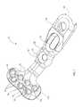
- FIG. 1is a top perspective view of a distal radius volar plate according to the invention
- FIG. 2is a bottom perspective view of the volar plate
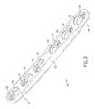
- FIG. 3is top perspective view of a fragment plate according to the invention.
- FIG. 4is an enlarged broken bottom perspective view of an end of the fragment plate
- FIG. 5is an enlarged broken top perspective view of an end of the fragment plate
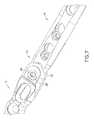
- FIG. 6is a top perspective view of the volar plate with the fragment plate inserted into the slot at the end of the volar plate stem;
- FIG. 7is an enlarged broken top perspective view showing the mating of the volar plate and the fragment plate with a set screw
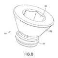
- FIG. 8is an enlarged perspective view of the set screw
- FIG. 9is a perspective view of a second embodiment of a modular plate system according to the invention.
- FIG. 10is a broken bottom perspective view of the embodiment of FIG. 9 ;
- FIG. 11is a broken top perspective exploded view of the embodiment of FIG. 9 ;
- FIG. 12is a broken bottom perspective exploded view of the embodiment of FIG. 9 ;
- FIG. 13is a broken top view of the embodiment of FIG. 9 ;
- FIG. 14is a section view across line 14 - 14 in FIG. 13 ;
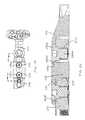
- FIG. 15is a perspective view of a third embodiment of a modular plate system according to the invention.
- FIG. 16is a broken bottom perspective view of the embodiment of FIG. 15 ;
- FIG. 17is a broken top perspective exploded view of the embodiment of FIG. 15 ;
- FIG. 18is a broken bottom perspective exploded view of the embodiment of FIG. 15 ;
- FIG. 19is a broken top view of the embodiment of FIG. 15 ;
- FIG. 20is a section view across line 20 - 20 in FIG. 19 .
- a distal radius volar fixation plate(or generally any ‘end’ plate or metaphyseal plate) 10 includes a distal head portion 12 and a proximal stem portion 14 .
- the plate 10corresponds to the plate described in previously incorporated U.S. Ser. No. 10/985,598.
- other metaphyseal platesfor different locations on the radius bone or even for placement on different bones or can be used.
- the head portion 12 of the volar fixation plate 10 shownhas a plurality of alignment holes 16 which are dimensioned to closely accept K-wires in a fixed angle relationship and two longitudinally offset rows 17 a , 17 b of screw holes 18 for receiving fixation elements therethrough.
- the screw holes 18are threaded, and as such are specifically adapted to receive locking screws and/or pegs that lock in axial alignment relative to the plate.
- the stem portion 14has at least one alignment hole 20 dimensioned to closely accept a K-wire and may optionally include one or more (two as illustrated) bone screw holes 22 , 24 . That is, the stem may be substantially shorter than shown and does not need to include a bone screw hole.
- the free end of the stem portion 14includes a socket in the form of a slot 26 (for receiving an end of the fragment plate 40 , described below) and an orthogonal set screw hole 28 intersecting the slot. As shown in FIGS. 1-8 , the slot 26 is open to the proximal end of the stem portion, and preferably is also open on the bottom side of the stem portion as well.
- the top side ( FIG. 1 ) of the volar plate 10has a topography of curved surfaces and recesses surrounding some of the holes to provide a low profile when seated on the anatomical bone surface.
- the bottom side ( FIG. 2 ) of the head portion 12is likewise constructed to conform to the anatomy, while the stem portion 14 , however presents a smooth surface.
- the bottom of the head portion 12lies in a first plane and the stem portion 14 lies in a second plane.
- a neck 30transitions between the two planes.
- the angle between the two planesis preferably approximately 25 degrees.
- the alignment holes and the bone screw holesare used as described in previously incorporated U.S. Ser. No. 10/985,598.
- the slot 26 and the set screw hole 28are used in conjunction with a fragment plate and a set screw as described in more detail below.
- the fragment plate 40is an elongate plate having a first end 42 and a second end 44 .
- a plurality of bone screw holes 46 , 48 , 50 , 52 , 54 , 56are spaced along the length of the plate for receiving bone screws, and a threaded set screw hole 58 , 60 , 62 , 64 , 66 , 68 is arranged adjacent each bone screw hole.
- screw holesare preferably any of the screw holes and associated locking systems described in U.S. Pub. No. 20050187551 A1, incorporated by reference herein, for the reasons and advantages provided therein, although any suitable bone screw hole may be used.
- the shape of the fragment plate 40 and the arrangement of holesare preferably longitudinally symmetrical about a mid point 70 .
- Each set screw holeis provided on a side of a bone screw hole closer to an end of the fragment plate than the midpoint of the plate, with a set screw hole 58 , 68 specifically being located at each end of the plate.
- the ends 42 , 44 of the plateare tapered as well as rounded. The taper occurs over a significant length which permits both a bone screw hole 46 , 56 and a set screw hole 58 , 68 to be located in the tapered ends 42 , 44 of each plate. Comparing FIGS. 4 and 5 with FIGS.
- ends 42 , 44 of the plate 40are shaped and dimensioned to fit neatly into the slot 26 of the volar plate 10 with the set screw hole 58 , 68 of the plate 40 aligning with the set screw hole 28 of the plate 10 .
- the taper at the end of the fragment plate 40permits the remainder of the fragment plate and the stem 14 of the end plate 10 to have substantially the same width, e.g., approximately 0.43′′ for a distal radius fixation system.
- both ends 42 , 44 of the fragment platepreferably have the same shape and features. Thus either end 42 , 44 may be inserted into the slot 26 of the plate.
- FIG. 6shows the end 42 of the plate 40 inserted into the slot 26 of the plate 10 .
- the tapered and rounded end 42 of the plate 40is shaped and dimensioned to fit neatly into the slot 26 of the volar plate 10 with the threaded set screw hole 58 of the plate 40 aligning with the unthreaded set screw hole 28 of the plate 10 .
- a set screw 80is inserted into the hole 28 as shown in FIG. 7 .
- the set screw 80is threaded into the threaded set screw hole 58 in the plate 40 . This secures the two plates together so that they function as a single piece.
- the distal radius plate and fragment platebe joined without reliance on the bone to join them. Otherwise, the tight interface and coupling between the plates could be compromised based on the quality of the bone, e.g., where such bone is fractured beneath the location of the coupling or where the bone is osteoporotic.
- the set screw 80has a frustoconical head 82 from which depends a threaded stem 84 .
- the head 82has a hex socket 86 adapted to receive a driver (not shown).
- the set screwprovides a secure lock between the two plates independent of the bone.
- each such holecan be used to lock the fragment plate to the volar plate, or may alternatively be used to lock an adjacent bone screw in a bone screw hole 46 , 56 in place.
- the relatively close thicknessesare possible, for one reason, in that the end plate does not need to support the compressive forces of bone screws at that location. Rather, as discussed above, the set screws used exert a substantially smaller force on the upper thinner portion of the end plate than would a cortical screw under compressive load.
- end plate and fragment plate componentsseparately machined or otherwise formed from each other, will invariably differ, within tolerances, from their specified designs. Such variations from predefined dimensions may cause the components when assembled to have some ‘play’. Any play between the components reduces the ability of the assembly to transfer load from one component to the other. Play also results in micromovement of the components that may hamper the healing process.
- the second and third embodimentsare provided.
- the end plate 110includes stem portion 114 that is larger in width and thickness at a free end opposite the head portion 112 .
- the underside of the free end 115is open defining a socket in the form of a cavity 126 into which a post 128 descends.
- the surface 129 from which the post descendsis flat.
- the cavity 126tapers in width and defines at an end a portion 130 stepped down in width.
- the end portiondefines opposing flat parallel wall portions 131 a , 131 b .
- the stem portion 114includes a slightly oval set screw hole 132 into the cavity, located between the post 128 and the stepped down portion 130 of the cavity.
- the centers of the post 128 and set screw hole 132are intended to be offset by a first distance within a defined tolerance.
- An oval cortical bone screw hole 134is also provided in the thinner portion of the stem.
- the fragment plate 140is similar to plate 40 , but includes ends 145 stepped down in width and sized to fit within the stepped down portion 130 of the cavity 126 . Such ends 145 include short opposing parallel flat sides 147 a , 147 b .
- the upper surface 150 of the fragment plate over the last threaded set screw hole 146 and bone screw hole 158i.e., that portion that will be received within the cavity, as described below
- the last set screw hole 146 and bone screw hole 158are offset from each other by a second distance within a defined tolerance. The second distance is slightly larger than the first defined distance.
- several of the screw holes, e.g., 160 ( FIG. 9 ), along the fragment plateare non-locking oblong cortical screw holes.
- the set screw 180includes a head 182 and a shaft 184 .
- Head 182defined by two frustoconical sections: the upper frustoconical section 182 a is angled to seat against the rim 132 a of the set screw hole 132 , whereas the lower frustoconical section 182 b is angle to seat within the upper portion 146 a of the set screw hole 146 at the end of the fragment plate.
- an end 145 of the fragment plateis positioned with the cavity 126 of the end plate 110 and the post 128 is inserted into bone screw hole 158 .
- the threads of set screw hole 146do not perfectly align with the center of non-threaded set screw hole 132 .
- the shaft 184 of the set screw 180is easily maneuvered through set screw hole 132 and into engaged within the threads of the screw hole 146 .
- the set screw 180provides a force to push the post 128 of the end plate 110 against the fragment plate (at 190 ) causing significant interference so as to remove any play.
- all forceis transferred from the end plate to the fragment plate.
- the flat sides 147 a , 147 b of the fragment platebeing in close contact with flat walls 131 a , 131 b limits rotation of the components relative to each other.
- the walls 131 a , 131 bare of sufficient length to accommodate the range of tolerances to which the components may be manufactured; i.e., so that flat sides 147 a , 147 b are always adjacent some portion of the flat walls 131 a , 131 b.
- FIGS. 15 through 20the third embodiment of a modular plate system, including an end plate 210 and a fragment plate 240 , is shown.
- the end plate 210is substantially similar to end plate 110 , with the following differences.
- the enlarged free endincludes a widthwise tapered cavity 226 provided with a post 228 , and two slightly oblong non-threaded set screw holes 232 , 233 entering the cavity 226 one on either side of the post 228 .
- Post 228 and screw hole 232are offset by a first distance within a defined tolerance.
- the thinner portion of the end plateincludes a preferably oblong non-threaded bone screw hole 234 .
- the fragment plate 240is similar to plate 140 with the following differences.
- the ends 245are rounded and do not include the stepped end.
- the last set screw hole 246 and bone screw hole 258are offset from each other by a second distance within a defined tolerance.
- Another machine threaded screw hole 260is provided independent of a cooperative non-threaded bone screw hole.
- the screw hole 260is preferably defined by two spaced apart cantilevers 262 , 264 set off from the interior of the plate by slots 266 , 268 extending generally parallel to the longitudinal axis of the plate.
- a recess 270is provided at the upper portion of the screw hole 260 .
- an end 245 of the fragment plateis positioned with the cavity 226 of the end plate 210 and the post 228 is inserted into bone screw hole 258 .
- the threads of set screw hole 246do not perfectly align with the center of non-threaded set screw hole 232 .
- the shaft 284 a of the set screw 280 ais easily maneuvered through set screw hole 232 and into engaged within the threads of the screw hole 246 .
- the set screw 280 aprovides a force to push the post 228 of the end plate 210 against the fragment plate (at 290 ) causing significant interference so as to remove any play.
- all forceis transferred from the end plate 210 to the fragment plate 240 .
- the second set screw 280 bis inserted into screw hole 233 .
- the chamfer of at the lower side of head portion 282 b ′contacts the chamfer about screw hole 233 regardless of the position of the end plate 210 relative to the fragment plate 240 .
- screw 280 blimits rotation of the components relative to each other.
- the end plate 210 at the socket 226has a thickness of approximately 0.17′′ and the fragment plate 240 has a thickness of 0.135′′ at the portion positioned within the socket.
- the thickness of the couplingis less than approximately 30 percent and approximately 26 percent.
- the second embodimentcan be constructed with similar relative dimensions.
- the end 245 a of the fragment plate 240 which is not coupled to the end plate 210also includes a machine threaded screw 260 a , as described above with respect to 260 .
- a machine threaded screw 260 aSuch screw hole 260 a and the associated framelike structure of the plate thereabout decreases the rigidity of the plate at that location.
- any cortical screw implanted into bone at the end 245 a , and the bone thereaboutwill be subject to reduced maximum stress.
- the end 245 a of the platecan be adjusted in rigidity. By inserting a set screw or other insert into screw hole 260 a the fragment plate is made more rigid. Recess 270 allows countersinking of such a set screw.
- the platemay have a flexibility of 0.003 inch, whereas with the set screw inserted, the flexibility is reduced to 0.001 inch. It is appreciated that in some circumstances it is desirable to have a fragment plate that is flexible at its ends, while in other instances, e.g., when the fracture is more comminuted, it is advantageous to have a plate that is less flexible during the healing process. In addition, assuming that a comminuted bone fracture completely heals after a period of time, it may be advantageous to have a plate that after healing allows the bone to function under normal conditions and does not produce high stress concentrations at the cortical screw-bone interface.
- the set screw or insertcan be bio-absorbable, maintaining needed fixation during the healing process, followed by absorption such that the plate has higher stiffness during healing and more flexible thereafter.
- the resultant plate systemwould be less likely to result in refracture due to the weakening attributed with drilling holes in the bone and then point loading at those holes.
- the plates 10 ( 10 , 210 ) and 40 ( 140 , 240 )are arranged in a kit containing several different size plates 10 and several different size fragment plates 40 .
- three different size volar platesare provided: standard, wide, and narrow.
- a plurality of different length fragment platesare also provided.
- the fragment platesmay be straight or curved.
- the fragment platescan be used alone or in combination with the volar plates.
- distal and mid-shaft fracturescan be covered with one integral plate (i.e. the two plates coupled to each other as shown in FIG. 7 ).
- the loadsare shared by the combined plate rather than the bone between two plates.
- the loadis thereby spread out rather than concentrated on the bone between two plates.
- the modularity of the different size platesallows for the assembly of a wide variety of combinations using only a few different sizes. For example, three different width volar plates packed together with five different length fragment plates can be used to construct fifteen different size combination plates using only eight different size pieces.
- the volar plateis not required to include a socket in the form of a slot or cavity for receiving an end portion of the fragment plate. Rather, a discrete coupler with sockets at two of its sides can be provided between the volar and fragment plates.
- the coupleroperates to “splice” together the metaphyseal volar plate and the diaphyseal fragment plate.
- the advantageis that the volar plate for use in the system can be a standard component without modification, and can therefore be used alone without the fragment plate. Thus, the surgical tray will need fewer of the more expensive volar plates.
- the couplerallows “splicing” of multiple diaphyseal fragment plates together to make one extra long plate.
- fixation plateand particularly plates for fixation of distal radius fractures. While particular embodiments of the invention have been described, it is not intended that the invention be limited thereto, as it is intended that the invention be as broad in scope as the art will allow and that the specification be read likewise. Thus, while particular preferred materials, dimensions, and relative angles for particular elements of the system have been disclosed, it will be appreciated that other materials, dimensions, and relative angles may be used as well.
- the inventionmay include other ‘end’ plates suitable in size and shape for placement at other metaphyseal locations, e.g., the dorsal side of the distal radius, the humerus, the femur and the tibia.
- end plates having shapes other than a ‘T’may also be used, such as lateral and medial columns (generally ‘L’-shaped), and plates having a flared or forked head, provided such end plates are dimensioned and configured for placement at the metaphysis.
- end plates having shapes other than a ‘T’may also be used, such as lateral and medial columns (generally ‘L’-shaped), and plates having a flared or forked head, provided such end plates are dimensioned and configured for placement at the metaphysis.
- Lmedial columns
Landscapes
- Health & Medical Sciences (AREA)
- Orthopedic Medicine & Surgery (AREA)
- Surgery (AREA)
- Life Sciences & Earth Sciences (AREA)
- Heart & Thoracic Surgery (AREA)
- Nuclear Medicine, Radiotherapy & Molecular Imaging (AREA)
- Engineering & Computer Science (AREA)
- Biomedical Technology (AREA)
- Neurology (AREA)
- Medical Informatics (AREA)
- Molecular Biology (AREA)
- Animal Behavior & Ethology (AREA)
- General Health & Medical Sciences (AREA)
- Public Health (AREA)
- Veterinary Medicine (AREA)
- Surgical Instruments (AREA)
Abstract
Description
Claims (11)
Priority Applications (14)
| Application Number | Priority Date | Filing Date | Title |
|---|---|---|---|
| US11/082,401US8062296B2 (en) | 2005-03-17 | 2005-03-17 | Modular fracture fixation plate system with multiple metaphyseal and diaphyseal plates |
| PCT/US2006/009717WO2006102081A1 (en) | 2005-03-17 | 2006-03-17 | Modular fracture fixation plate system |
| US11/378,703US8394098B2 (en) | 2005-03-17 | 2006-03-17 | Modular fracture fixation plate system |
| AU2006228012AAU2006228012B2 (en) | 2005-03-17 | 2006-03-17 | Modular fracture fixation plate system |
| EP06738741.5AEP1861032B1 (en) | 2005-03-17 | 2006-03-17 | Modular fracture fixation plate system |
| US11/557,429US7867261B2 (en) | 2006-03-17 | 2006-11-07 | Bone plate with variable torsional stiffness at fixed angle holes |
| ES07758037.1TES2625603T3 (en) | 2006-03-17 | 2007-03-07 | Modular fracture fixing plate system |
| JP2009500553AJP5215285B2 (en) | 2006-03-17 | 2007-03-07 | Modular fracture fixation plate system |
| AU2007227170AAU2007227170C1 (en) | 2006-03-17 | 2007-03-07 | Modular fracture fixation plate system |
| EP07758037.1AEP1996095B1 (en) | 2005-03-17 | 2007-03-07 | Modular fracture fixation plate system |
| CA2646433ACA2646433C (en) | 2006-03-17 | 2007-03-07 | Modular fracture fixation plate system |
| PCT/US2007/063448WO2007109417A2 (en) | 2005-03-17 | 2007-03-07 | Modular fracture fixation plate system |
| ZA200808860AZA200808860B (en) | 2006-03-17 | 2008-10-16 | Modular fracture fixation plate system |
| US14/295,808US9526543B2 (en) | 2004-11-10 | 2014-06-04 | Modular fracture fixation system |
Applications Claiming Priority (2)
| Application Number | Priority Date | Filing Date | Title |
|---|---|---|---|
| US11/082,401US8062296B2 (en) | 2005-03-17 | 2005-03-17 | Modular fracture fixation plate system with multiple metaphyseal and diaphyseal plates |
| US11/378,703US8394098B2 (en) | 2005-03-17 | 2006-03-17 | Modular fracture fixation plate system |
Related Parent Applications (1)
| Application Number | Title | Priority Date | Filing Date |
|---|---|---|---|
| US11/082,401Continuation-In-PartUS8062296B2 (en) | 2004-11-10 | 2005-03-17 | Modular fracture fixation plate system with multiple metaphyseal and diaphyseal plates |
Related Child Applications (1)
| Application Number | Title | Priority Date | Filing Date |
|---|---|---|---|
| US11/536,441Continuation-In-PartUS8394130B2 (en) | 2004-11-10 | 2006-09-28 | Modular fracture fixation system |
Publications (2)
| Publication Number | Publication Date |
|---|---|
| US20060235404A1 US20060235404A1 (en) | 2006-10-19 |
| US8394098B2true US8394098B2 (en) | 2013-03-12 |
Family
ID=39877998
Family Applications (2)
| Application Number | Title | Priority Date | Filing Date |
|---|---|---|---|
| US11/082,401Active2029-09-29US8062296B2 (en) | 2004-11-10 | 2005-03-17 | Modular fracture fixation plate system with multiple metaphyseal and diaphyseal plates |
| US11/378,703Active2030-03-31US8394098B2 (en) | 2004-11-10 | 2006-03-17 | Modular fracture fixation plate system |
Family Applications Before (1)
| Application Number | Title | Priority Date | Filing Date |
|---|---|---|---|
| US11/082,401Active2029-09-29US8062296B2 (en) | 2004-11-10 | 2005-03-17 | Modular fracture fixation plate system with multiple metaphyseal and diaphyseal plates |
Country Status (8)
| Country | Link |
|---|---|
| US (2) | US8062296B2 (en) |
| EP (2) | EP1861032B1 (en) |
| JP (1) | JP5215285B2 (en) |
| AU (2) | AU2006228012B2 (en) |
| CA (1) | CA2646433C (en) |
| ES (1) | ES2625603T3 (en) |
| WO (2) | WO2006102081A1 (en) |
| ZA (1) | ZA200808860B (en) |
Cited By (38)
| Publication number | Priority date | Publication date | Assignee | Title |
|---|---|---|---|---|
| US20120130371A1 (en)* | 2009-08-14 | 2012-05-24 | Xinhua Hospital Affiliated To Shanghai Jiaotong University School Of Medicine | Steel plate for funnel chest orthopaedic surgery |
| US9468479B2 (en) | 2013-09-06 | 2016-10-18 | Cardinal Health 247, Inc. | Bone plate |
| US9526543B2 (en) | 2004-11-10 | 2016-12-27 | Biomet C.V. | Modular fracture fixation system |
| US9649141B2 (en) | 2010-05-07 | 2017-05-16 | Mcginley Engineered Solutions, Llc | System for treating bone fractures |
| US9833270B2 (en) | 2013-09-19 | 2017-12-05 | Mcginley Engineered Solutions, Llc | Variable angle blade plate system and method |
| US10368928B2 (en) | 2017-03-13 | 2019-08-06 | Globus Medical, Inc. | Bone stabilization systems |
| US10383668B2 (en) | 2016-08-17 | 2019-08-20 | Globus Medical, Inc. | Volar distal radius stabilization system |
| US10420596B2 (en) | 2016-08-17 | 2019-09-24 | Globus Medical, Inc. | Volar distal radius stabilization system |
| US10517656B2 (en) | 2011-06-17 | 2019-12-31 | Biedermann Technologies Gmbh & Co. Kg | Modular bone plate and member of such a modular bone plate |
| US10575884B2 (en) | 2016-08-17 | 2020-03-03 | Globus Medical, Inc. | Fracture plates, systems, and methods |
| US10631903B2 (en) | 2017-03-10 | 2020-04-28 | Globus Medical Inc. | Clavicle fixation system |
| US10687874B2 (en) | 2015-08-27 | 2020-06-23 | Globus Medical, Inc | Proximal humeral stabilization system |
| US10687873B2 (en) | 2016-08-17 | 2020-06-23 | Globus Medical Inc. | Stabilization systems |
| US10751098B2 (en) | 2016-08-17 | 2020-08-25 | Globus Medical Inc. | Stabilization systems |
| US10828074B2 (en) | 2015-11-20 | 2020-11-10 | Globus Medical, Inc. | Expandalbe intramedullary systems and methods of using the same |
| US10828075B2 (en) | 2015-09-25 | 2020-11-10 | Globus Medical Inc. | Bone fixation devices having a locking feature |
| US10856920B2 (en) | 2017-09-13 | 2020-12-08 | Globus Medical Inc. | Bone stabilization systems |
| US10905477B2 (en) | 2017-03-13 | 2021-02-02 | Globus Medical, Inc. | Bone stabilization systems |
| US11071570B2 (en) | 2018-03-02 | 2021-07-27 | Globus Medical, Inc. | Distal tibial plating system |
| US11076898B2 (en) | 2015-08-27 | 2021-08-03 | Globus Medical, Inc. | Proximal humeral stabilization system |
| US11096730B2 (en) | 2017-09-13 | 2021-08-24 | Globus Medical Inc. | Bone stabilization systems |
| US11129627B2 (en) | 2019-10-30 | 2021-09-28 | Globus Medical, Inc. | Method and apparatus for inserting a bone plate |
| US11141172B2 (en) | 2018-04-11 | 2021-10-12 | Globus Medical, Inc. | Method and apparatus for locking a drill guide in a polyaxial hole |
| US11141204B2 (en) | 2016-08-17 | 2021-10-12 | Globus Medical Inc. | Wrist stabilization systems |
| US11197682B2 (en) | 2015-08-27 | 2021-12-14 | Globus Medical, Inc. | Proximal humeral stabilization system |
| US11197701B2 (en) | 2016-08-17 | 2021-12-14 | Globus Medical, Inc. | Stabilization systems |
| US11197704B2 (en) | 2016-04-19 | 2021-12-14 | Globus Medical, Inc. | Implantable compression screws |
| US11202663B2 (en) | 2019-02-13 | 2021-12-21 | Globus Medical, Inc. | Proximal humeral stabilization systems and methods thereof |
| US11213327B2 (en) | 2016-08-17 | 2022-01-04 | Globus Medical, Inc. | Fracture plates, systems, and methods |
| US11224468B2 (en) | 2018-03-02 | 2022-01-18 | Globus Medical, Inc. | Distal tibial plating system |
| US11284920B2 (en) | 2016-03-02 | 2022-03-29 | Globus Medical Inc. | Fixators for bone stabilization and associated systems and methods |
| US11331128B2 (en) | 2016-08-17 | 2022-05-17 | Globus Medical Inc. | Distal radius stabilization system |
| US11432857B2 (en) | 2016-08-17 | 2022-09-06 | Globus Medical, Inc. | Stabilization systems |
| US11723647B2 (en) | 2019-12-17 | 2023-08-15 | Globus Medical, Inc. | Syndesmosis fixation assembly |
| US12042200B2 (en) | 2016-09-22 | 2024-07-23 | Globus Medical, Inc. | Systems and methods for intramedullary nail implantation |
| US12064150B2 (en) | 2022-01-19 | 2024-08-20 | Globus Medical Inc. | System and method for treating bone fractures |
| US12185995B2 (en) | 2019-10-09 | 2025-01-07 | Globus Medical, Inc. | Bone stabilization systems |
| US12279795B2 (en) | 2017-09-13 | 2025-04-22 | Globus Medical, Inc. | Bone stabilization systems |
Families Citing this family (57)
| Publication number | Priority date | Publication date | Assignee | Title |
|---|---|---|---|---|
| US8062296B2 (en) | 2005-03-17 | 2011-11-22 | Depuy Products, Inc. | Modular fracture fixation plate system with multiple metaphyseal and diaphyseal plates |
| US8070749B2 (en) | 2005-05-12 | 2011-12-06 | Stern Joseph D | Revisable anterior cervical plating system |
| US7867261B2 (en)* | 2006-03-17 | 2011-01-11 | Depuy Products, Inc. | Bone plate with variable torsional stiffness at fixed angle holes |
| BRPI0601069B1 (en)* | 2006-03-17 | 2014-10-14 | Gm Dos Reis Ind E Com Ltda | BONE BOARD |
| US20120029576A1 (en)* | 2006-05-26 | 2012-02-02 | Mark Richard Cunliffe | Bone Fixation Device |
| US10085780B2 (en) | 2006-05-26 | 2018-10-02 | Mark Richard Cunliffe | Bone fixation device |
| US8398687B2 (en)* | 2006-12-06 | 2013-03-19 | Amei Technologies, Inc. | Volar plate fixation device |
| US20100137996A1 (en) | 2007-05-01 | 2010-06-03 | Moximed, Inc. | Femoral and tibial base components |
| US20080275567A1 (en) | 2007-05-01 | 2008-11-06 | Exploramed Nc4, Inc. | Extra-Articular Implantable Mechanical Energy Absorbing Systems |
| US8894714B2 (en) | 2007-05-01 | 2014-11-25 | Moximed, Inc. | Unlinked implantable knee unloading device |
| US20110245928A1 (en) | 2010-04-06 | 2011-10-06 | Moximed, Inc. | Femoral and Tibial Bases |
| US10022154B2 (en) | 2007-05-01 | 2018-07-17 | Moximed, Inc. | Femoral and tibial base components |
| US7655041B2 (en) | 2007-05-01 | 2010-02-02 | Moximed, Inc. | Extra-articular implantable mechanical energy absorbing systems and implantation method |
| US8409281B2 (en) | 2007-05-01 | 2013-04-02 | Moximed, Inc. | Adjustable absorber designs for implantable device |
| US9907645B2 (en) | 2007-05-01 | 2018-03-06 | Moximed, Inc. | Adjustable absorber designs for implantable device |
| EP2224868B1 (en)* | 2007-11-21 | 2014-07-30 | Globus Medical, Inc. | Cervical spine stabilization system with extendable plates |
| US8628533B2 (en)* | 2008-05-08 | 2014-01-14 | The Cleveland Clinic Foundation | Bone plate with reduction aids and methods of use thereof |
| US8608783B2 (en)* | 2008-05-08 | 2013-12-17 | The Cleveland Clinic Foundation | Bone plate with flange member and methods of use thereof |
| EP2328519B1 (en)* | 2008-06-05 | 2014-12-31 | Alphatec Spine, Inc. | Modular anterior locking interbody cage |
| US8282674B2 (en)* | 2008-07-18 | 2012-10-09 | Suspension Orthopaedic Solutions, Inc. | Clavicle fixation |
| US8808333B2 (en) | 2009-07-06 | 2014-08-19 | Zimmer Gmbh | Periprosthetic bone plates |
| CA2771332C (en) | 2009-08-27 | 2020-11-10 | Cotera, Inc. | Method and apparatus for force redistribution in articular joints |
| US9668868B2 (en) | 2009-08-27 | 2017-06-06 | Cotera, Inc. | Apparatus and methods for treatment of patellofemoral conditions |
| US9861408B2 (en) | 2009-08-27 | 2018-01-09 | The Foundry, Llc | Method and apparatus for treating canine cruciate ligament disease |
| US9278004B2 (en) | 2009-08-27 | 2016-03-08 | Cotera, Inc. | Method and apparatus for altering biomechanics of the articular joints |
| US10349980B2 (en) | 2009-08-27 | 2019-07-16 | The Foundry, Llc | Method and apparatus for altering biomechanics of the shoulder |
| CH702194A2 (en)* | 2009-11-05 | 2011-05-13 | Cristiano Hossri Ribeiro | Plate multi - adjustable osteotomy. |
| JP2013512042A (en) | 2009-11-27 | 2013-04-11 | シンセス ゲゼルシャフト ミット ベシュレンクテル ハフツング | Planar fixation concept for distal radius fractures |
| FR2956971B1 (en) | 2010-03-08 | 2012-03-02 | Memometal Technologies | PLATE OSTEOSYNTHESIS SYSTEM |
| FR2956972B1 (en)* | 2010-03-08 | 2012-12-28 | Memometal Technologies | ARTICULATED OSTEOSYNTHESIS PLATE |
| US20110218580A1 (en)* | 2010-03-08 | 2011-09-08 | Stryker Trauma Sa | Bone fixation system with curved profile threads |
| US8961573B2 (en) | 2010-10-05 | 2015-02-24 | Toby Orthopaedics, Inc. | System and method for facilitating repair and reattachment of comminuted bone portions |
| WO2012058448A2 (en) | 2010-10-27 | 2012-05-03 | Toby Orthopaedics, Llc | System and method for fracture replacement of comminuted bone fractures or portions thereof adjacent bone joints |
| WO2012119146A2 (en) | 2011-03-03 | 2012-09-07 | Toby Orthopaedics, Llc | Anterior lesser tuberosity fixed angle fixation device and method of use associated therewith |
| US9044270B2 (en) | 2011-03-29 | 2015-06-02 | Moximed, Inc. | Apparatus for controlling a load on a hip joint |
| WO2013036582A1 (en)* | 2011-09-06 | 2013-03-14 | Skeletal Dynamics, L.L.C. | Fracture fixation plate, system and methods of use |
| WO2013036362A1 (en) | 2011-09-06 | 2013-03-14 | Synthes Usa, Llc | Pancarpal arthrodesis bone plate |
| US9271772B2 (en) | 2011-10-27 | 2016-03-01 | Toby Orthopaedics, Inc. | System and method for fracture replacement of comminuted bone fractures or portions thereof adjacent bone joints |
| US9730797B2 (en) | 2011-10-27 | 2017-08-15 | Toby Orthopaedics, Inc. | Bone joint replacement and repair assembly and method of repairing and replacing a bone joint |
| US9402667B2 (en) | 2011-11-09 | 2016-08-02 | Eduardo Gonzalez-Hernandez | Apparatus and method for use of the apparatus for fracture fixation of the distal humerus |
| US9468466B1 (en) | 2012-08-24 | 2016-10-18 | Cotera, Inc. | Method and apparatus for altering biomechanics of the spine |
| BR102012026028A2 (en)* | 2012-10-11 | 2014-10-21 | Jose Alberto Angeli | DIAPHYSARY AND METAPHYSARY STRETCHER |
| US20140148859A1 (en)* | 2012-11-27 | 2014-05-29 | Solana Surgical, Llc | Orthopedic fusion plate and compression screw |
| US9283008B2 (en) | 2012-12-17 | 2016-03-15 | Toby Orthopaedics, Inc. | Bone plate for plate osteosynthesis and method for use thereof |
| US9241747B2 (en) | 2012-12-19 | 2016-01-26 | Industrial Technology Research Institute | Bone plate structure, surgery device and method for bone plate implant |
| US9333014B2 (en)* | 2013-03-15 | 2016-05-10 | Eduardo Gonzalez-Hernandez | Bone fixation and reduction apparatus and method for fixation and reduction of a distal bone fracture and malunion |
| US9814503B1 (en)* | 2014-04-14 | 2017-11-14 | Avanti Orthopaedics, LLC | Load sharing bone plate |
| EP3164093B1 (en) | 2014-07-03 | 2024-02-14 | Acumed LLC | Bone plate with movable joint |
| USD779065S1 (en) | 2014-10-08 | 2017-02-14 | Nuvasive, Inc. | Anterior cervical bone plate |
| ITUB20153645A1 (en)* | 2015-09-15 | 2017-03-15 | Sim Soluzioni Innovative Medicali Sagl | Modular osteosynthesis plate |
| JP2020509863A (en) | 2017-03-13 | 2020-04-02 | デピュイ・シンセス・プロダクツ・インコーポレイテッド | Proximal femoral plate system |
| CN107928774B (en)* | 2017-12-06 | 2024-05-28 | 上海凯利泰医疗科技股份有限公司 | Tibia proximal end outside locking plate |
| CN108210057A (en)* | 2018-03-15 | 2018-06-29 | 泰州市人民医院 | For the inner fixing device of fracture of distal radius |
| US11259852B2 (en)* | 2019-08-28 | 2022-03-01 | DePuy Synthes Products, Inc. | Plate connection |
| US11871969B2 (en) | 2021-03-03 | 2024-01-16 | Acustitch, Llc | System and method for osseous reconstruction and repair and implant device |
| US12343050B2 (en) | 2021-08-17 | 2025-07-01 | Ps Ortho Llc | Bone fixation devices, systems, and methods |
| US20240245436A1 (en)* | 2023-01-23 | 2024-07-25 | Acumed Llc | Adjustable joint optimizations |
Citations (62)
| Publication number | Priority date | Publication date | Assignee | Title |
|---|---|---|---|---|
| US1105105A (en) | 1912-02-10 | 1914-07-28 | William O'n Sherman | Surgical appliance. |
| US2406832A (en) | 1945-03-05 | 1946-09-03 | Mervyn G Hardinge | Fracture plate |
| US2486303A (en) | 1948-04-29 | 1949-10-25 | Harry Herschel Leiter | Surgical appliance for bone fractures |
| US3488779A (en) | 1967-09-27 | 1970-01-13 | Robert W Christensen | Orthopedic prosthetic appliances for attachment to bone |
| US3695259A (en) | 1970-11-10 | 1972-10-03 | Clyde E Yost | Bone plate |
| FR2367479A1 (en) | 1976-10-18 | 1978-05-12 | Bazelaire Eric De | Flexible surgical plate for use in osteosynthesis - has curved external surfaces providing cross sections reducing to outer edges for flexibility |
| US4219015A (en) | 1977-04-22 | 1980-08-26 | Institut Straumann Ag | Plates for osteosynthesis |
| GB2072514A (en) | 1980-03-27 | 1981-10-07 | Nat Res Dev | Orthopaedic implants |
| US4506662A (en) | 1981-06-18 | 1985-03-26 | Mecron Medizinische Produkte Gmbh | Nail for fixing a fracture of the femur |
| US4683878A (en) | 1985-04-29 | 1987-08-04 | Kirschner Medical Corporation | Osteosynthetic fixation plate |
| US4776330A (en) | 1986-06-23 | 1988-10-11 | Pfizer Hospital Products Group, Inc. | Modular femoral fixation system |
| US4781183A (en) | 1986-08-27 | 1988-11-01 | American Cyanamid Company | Surgical prosthesis |
| US4867144A (en) | 1986-04-14 | 1989-09-19 | Huta Baildon | Plate for connecting base splinters with bone shafts |
| US4955886A (en) | 1988-04-01 | 1990-09-11 | The Trustees Of Columbia University In The City Of New York | Dual-taper, asymmetric hole placement in reconstruction and fracture plates |
| US4957497A (en) | 1984-10-27 | 1990-09-18 | Thomas Hoogland | Device for osteosynthesis |
| US5002544A (en) | 1987-12-02 | 1991-03-26 | Synthes (U.S.A.) | Osteosynthetic pressure plate osteosynthetic compression plate |
| US5015248A (en) | 1990-06-11 | 1991-05-14 | New York Society For The Relief Of The Ruptured & Crippled, Maintaining The Hospital For Special Surgery | Bone fracture fixation device |
| US5053036A (en) | 1987-11-03 | 1991-10-01 | Synthes (U.S.A.) | Point contact bone compression plate |
| US5127914A (en)* | 1989-02-10 | 1992-07-07 | Calderale Pasquale M | Osteosynthesis means for the connection of bone fracture segments |
| US5129899A (en) | 1991-03-27 | 1992-07-14 | Smith & Nephew Richards Inc. | Bone fixation apparatus |
| US5190544A (en) | 1986-06-23 | 1993-03-02 | Pfizer Hospital Products Group, Inc. | Modular femoral fixation system |
| US5209751A (en) | 1992-02-19 | 1993-05-11 | Danek Medical, Inc. | Spinal fixation system |
| US5364399A (en)* | 1993-02-05 | 1994-11-15 | Danek Medical, Inc. | Anterior cervical plating system |
| US5474553A (en) | 1989-04-18 | 1995-12-12 | Rainer Baumgart | System for setting tubular bone fractures |
| US5484439A (en)* | 1992-09-16 | 1996-01-16 | Alphatec Manufacturing, Inc. | Modular femur fixation device |
| US5578036A (en) | 1993-12-06 | 1996-11-26 | Stone; Kevin T. | Method and apparatus for fixation of bone during surgical procedures |
| US5601553A (en) | 1994-10-03 | 1997-02-11 | Synthes (U.S.A.) | Locking plate and bone screw |
| US5616142A (en) | 1994-07-20 | 1997-04-01 | Yuan; Hansen A. | Vertebral auxiliary fixation device |
| US5620445A (en) | 1994-07-15 | 1997-04-15 | Brosnahan; Robert | Modular intramedullary nail |
| EP0773004A1 (en) | 1995-11-07 | 1997-05-14 | IMPLANTS ORTHOPEDIQUES TOUTES APPLICATIONS, S.A.R.L. dite: | Osteotomy plate for angle correction |
| US5733287A (en) | 1994-05-24 | 1998-03-31 | Synthes (U.S.A.) | Bone plate |
| US5827286A (en)* | 1997-02-14 | 1998-10-27 | Incavo; Stephen J. | Incrementally adjustable tibial osteotomy fixation device and method |
| US5906644A (en) | 1996-08-30 | 1999-05-25 | Powell; Douglas Hunter | Adjustable modular orthopedic implant |
| WO1999044529A1 (en) | 1998-03-06 | 1999-09-10 | Bionx Implants Oy | Bioabsorbable, deformable fixation plate |
| JPH11290359A (en) | 1998-03-26 | 1999-10-26 | Girielmo Victorio Brukman | External auxiliary implement for treating fracture in radius tip part |
| JPH11299804A (en) | 1998-04-16 | 1999-11-02 | Homuzu Giken:Kk | Osteosynthesis device |
| US5975904A (en) | 1997-12-05 | 1999-11-02 | Spiegel; Jeffrey H. | Articulated bone reconstruction bar |
| US6001099A (en) | 1998-06-08 | 1999-12-14 | Huebner; Randall J. | Bone plate with varying rigidity |
| US6340362B1 (en) | 1998-01-22 | 2002-01-22 | Impaq Gmbh Medizintechnik | Plate for joining a pelvic fracture |
| US20020013586A1 (en)* | 2000-03-01 | 2002-01-31 | Justis Jeff R. | Superelastic spinal stabilization system and method |
| US6383186B1 (en) | 1997-02-11 | 2002-05-07 | Gary K. Michelson | Single-lock skeletal plating system |
| JP2003052709A (en) | 2001-08-21 | 2003-02-25 | Mizuho Co Ltd | Cementation tool for thighbone |
| US20030060828A1 (en) | 2001-06-06 | 2003-03-27 | Michelson Gary K. | Dynamic multilock anterior cervical plate system having non-detachably fastened and moveable segments, instrumentation, and method for installation thereof |
| US6645208B2 (en) | 2000-11-08 | 2003-11-11 | Aesculap Ag & Co. Kg | Osteosynthesis plating apparatus and method with extension plate |
| US6669700B1 (en) | 1997-05-15 | 2003-12-30 | Sdgi Holdings, Inc. | Anterior cervical plating system |
| US6699249B2 (en) | 1999-05-14 | 2004-03-02 | Synthes (U.S.A.) | Bone fixation device with a rotation joint |
| US20040087953A1 (en) | 2002-05-15 | 2004-05-06 | Wamis Singhatat | Cross-pin graft fixation, instruments, and methods |
| US20040102778A1 (en) | 2002-11-19 | 2004-05-27 | Huebner Randall J. | Adjustable bone plates |
| US20040167521A1 (en)* | 2001-04-24 | 2004-08-26 | Paul De Windt | Fixing device for fixing vertebra parts |
| US20040193155A1 (en) | 2003-03-27 | 2004-09-30 | Hand Innovations, Inc. | Fracture fixation plate with particular plate hole and fastener engagement and methods of using the same |
| US20040210221A1 (en)* | 2000-10-25 | 2004-10-21 | Jeffrey Kozak | Anterior lumbar plate and method |
| US20040260291A1 (en)* | 2003-06-20 | 2004-12-23 | Jensen David G. | Bone plates with intraoperatively tapped apertures |
| US20050049594A1 (en) | 2001-04-20 | 2005-03-03 | Wack Michael A. | Dual locking plate and associated method |
| US20050154392A1 (en) | 2004-01-08 | 2005-07-14 | Medoff Robert J. | Fracture fixation system |
| US20050187551A1 (en) | 2002-12-02 | 2005-08-25 | Orbay Jorge L. | Bone plate system with bone screws fixed by secondary compression |
| US20050240187A1 (en) | 2004-04-22 | 2005-10-27 | Huebner Randall J | Expanded fixation of bones |
| US20060100625A1 (en) | 2004-10-28 | 2006-05-11 | Ralph James D | Adjustable bone plate |
| WO2006102081A1 (en) | 2005-03-17 | 2006-09-28 | Depuy Products, Inc. | Modular fracture fixation plate system |
| US20070260244A1 (en) | 2004-07-19 | 2007-11-08 | Dietmar Wolter | Bone-Fixation System and Filler Element for Bone-Fixation |
| US7604657B2 (en) | 2005-09-19 | 2009-10-20 | Depuy Products, Inc. | Bone fixation plate with complex suture anchor locations |
| US7635381B2 (en) | 2003-03-27 | 2009-12-22 | Depuy Products, Inc. | Anatomical distal radius fracture fixation plate with fixed-angle K-wire holes defining a three-dimensional surface |
| US8128628B2 (en) | 2002-02-01 | 2012-03-06 | Zimmer Spine, Inc. | Spinal plate system for stabilizing a portion of a spine |
Family Cites Families (1)
| Publication number | Priority date | Publication date | Assignee | Title |
|---|---|---|---|---|
| US7537604B2 (en) | 2002-11-19 | 2009-05-26 | Acumed Llc | Bone plates with slots |
- 2005
- 2005-03-17USUS11/082,401patent/US8062296B2/enactiveActive
- 2006
- 2006-03-17AUAU2006228012Apatent/AU2006228012B2/enactiveActive
- 2006-03-17WOPCT/US2006/009717patent/WO2006102081A1/enactiveSearch and Examination
- 2006-03-17EPEP06738741.5Apatent/EP1861032B1/enactiveActive
- 2006-03-17USUS11/378,703patent/US8394098B2/enactiveActive
- 2007
- 2007-03-07AUAU2007227170Apatent/AU2007227170C1/enactiveActive
- 2007-03-07JPJP2009500553Apatent/JP5215285B2/enactiveActive
- 2007-03-07WOPCT/US2007/063448patent/WO2007109417A2/enactiveApplication Filing
- 2007-03-07ESES07758037.1Tpatent/ES2625603T3/enactiveActive
- 2007-03-07CACA2646433Apatent/CA2646433C/enactiveActive
- 2007-03-07EPEP07758037.1Apatent/EP1996095B1/enactiveActive
- 2008
- 2008-10-16ZAZA200808860Apatent/ZA200808860B/enunknown
Patent Citations (70)
| Publication number | Priority date | Publication date | Assignee | Title |
|---|---|---|---|---|
| US1105105A (en) | 1912-02-10 | 1914-07-28 | William O'n Sherman | Surgical appliance. |
| US2406832A (en) | 1945-03-05 | 1946-09-03 | Mervyn G Hardinge | Fracture plate |
| US2486303A (en) | 1948-04-29 | 1949-10-25 | Harry Herschel Leiter | Surgical appliance for bone fractures |
| US3488779A (en) | 1967-09-27 | 1970-01-13 | Robert W Christensen | Orthopedic prosthetic appliances for attachment to bone |
| US3695259A (en) | 1970-11-10 | 1972-10-03 | Clyde E Yost | Bone plate |
| FR2367479A1 (en) | 1976-10-18 | 1978-05-12 | Bazelaire Eric De | Flexible surgical plate for use in osteosynthesis - has curved external surfaces providing cross sections reducing to outer edges for flexibility |
| US4219015A (en) | 1977-04-22 | 1980-08-26 | Institut Straumann Ag | Plates for osteosynthesis |
| GB2072514A (en) | 1980-03-27 | 1981-10-07 | Nat Res Dev | Orthopaedic implants |
| US4506662A (en) | 1981-06-18 | 1985-03-26 | Mecron Medizinische Produkte Gmbh | Nail for fixing a fracture of the femur |
| US4957497A (en) | 1984-10-27 | 1990-09-18 | Thomas Hoogland | Device for osteosynthesis |
| US4683878A (en) | 1985-04-29 | 1987-08-04 | Kirschner Medical Corporation | Osteosynthetic fixation plate |
| US4867144A (en) | 1986-04-14 | 1989-09-19 | Huta Baildon | Plate for connecting base splinters with bone shafts |
| EP0471419A2 (en) | 1986-06-23 | 1992-02-19 | Howmedica Inc. | Modular femoral fixation system |
| US5772662A (en) | 1986-06-23 | 1998-06-30 | Howmedica Inc. | Femoral fixation system |
| US5041114A (en) | 1986-06-23 | 1991-08-20 | Pfizer Hospital Products Group, Inc. | Modular femoral fixation system |
| US5364398A (en) | 1986-06-23 | 1994-11-15 | Pfizer Hospital Products Group, Inc. | Modular femoral fixation system |
| US4776330A (en) | 1986-06-23 | 1988-10-11 | Pfizer Hospital Products Group, Inc. | Modular femoral fixation system |
| JPH11128245A (en) | 1986-06-23 | 1999-05-18 | Howmedica Inc | Fixing device for treating bone |
| US5190544A (en) | 1986-06-23 | 1993-03-02 | Pfizer Hospital Products Group, Inc. | Modular femoral fixation system |
| US4781183A (en) | 1986-08-27 | 1988-11-01 | American Cyanamid Company | Surgical prosthesis |
| US5053036A (en) | 1987-11-03 | 1991-10-01 | Synthes (U.S.A.) | Point contact bone compression plate |
| US5002544A (en) | 1987-12-02 | 1991-03-26 | Synthes (U.S.A.) | Osteosynthetic pressure plate osteosynthetic compression plate |
| US4955886A (en) | 1988-04-01 | 1990-09-11 | The Trustees Of Columbia University In The City Of New York | Dual-taper, asymmetric hole placement in reconstruction and fracture plates |
| US5127914A (en)* | 1989-02-10 | 1992-07-07 | Calderale Pasquale M | Osteosynthesis means for the connection of bone fracture segments |
| US5474553A (en) | 1989-04-18 | 1995-12-12 | Rainer Baumgart | System for setting tubular bone fractures |
| US5015248A (en) | 1990-06-11 | 1991-05-14 | New York Society For The Relief Of The Ruptured & Crippled, Maintaining The Hospital For Special Surgery | Bone fracture fixation device |
| US5129899A (en) | 1991-03-27 | 1992-07-14 | Smith & Nephew Richards Inc. | Bone fixation apparatus |
| US5209751A (en) | 1992-02-19 | 1993-05-11 | Danek Medical, Inc. | Spinal fixation system |
| US5484439A (en)* | 1992-09-16 | 1996-01-16 | Alphatec Manufacturing, Inc. | Modular femur fixation device |
| US5364399A (en)* | 1993-02-05 | 1994-11-15 | Danek Medical, Inc. | Anterior cervical plating system |
| US5578036A (en) | 1993-12-06 | 1996-11-26 | Stone; Kevin T. | Method and apparatus for fixation of bone during surgical procedures |
| US5733287A (en) | 1994-05-24 | 1998-03-31 | Synthes (U.S.A.) | Bone plate |
| US5620445A (en) | 1994-07-15 | 1997-04-15 | Brosnahan; Robert | Modular intramedullary nail |
| US5616142A (en) | 1994-07-20 | 1997-04-01 | Yuan; Hansen A. | Vertebral auxiliary fixation device |
| US5601553A (en) | 1994-10-03 | 1997-02-11 | Synthes (U.S.A.) | Locking plate and bone screw |
| EP0773004A1 (en) | 1995-11-07 | 1997-05-14 | IMPLANTS ORTHOPEDIQUES TOUTES APPLICATIONS, S.A.R.L. dite: | Osteotomy plate for angle correction |
| US5906644A (en) | 1996-08-30 | 1999-05-25 | Powell; Douglas Hunter | Adjustable modular orthopedic implant |
| US6383186B1 (en) | 1997-02-11 | 2002-05-07 | Gary K. Michelson | Single-lock skeletal plating system |
| US5827286A (en)* | 1997-02-14 | 1998-10-27 | Incavo; Stephen J. | Incrementally adjustable tibial osteotomy fixation device and method |
| US6669700B1 (en) | 1997-05-15 | 2003-12-30 | Sdgi Holdings, Inc. | Anterior cervical plating system |
| US5975904A (en) | 1997-12-05 | 1999-11-02 | Spiegel; Jeffrey H. | Articulated bone reconstruction bar |
| US6340362B1 (en) | 1998-01-22 | 2002-01-22 | Impaq Gmbh Medizintechnik | Plate for joining a pelvic fracture |
| WO1999044529A1 (en) | 1998-03-06 | 1999-09-10 | Bionx Implants Oy | Bioabsorbable, deformable fixation plate |
| JPH11290359A (en) | 1998-03-26 | 1999-10-26 | Girielmo Victorio Brukman | External auxiliary implement for treating fracture in radius tip part |
| JPH11299804A (en) | 1998-04-16 | 1999-11-02 | Homuzu Giken:Kk | Osteosynthesis device |
| US6001099A (en) | 1998-06-08 | 1999-12-14 | Huebner; Randall J. | Bone plate with varying rigidity |
| US6699249B2 (en) | 1999-05-14 | 2004-03-02 | Synthes (U.S.A.) | Bone fixation device with a rotation joint |
| US20020013586A1 (en)* | 2000-03-01 | 2002-01-31 | Justis Jeff R. | Superelastic spinal stabilization system and method |
| US20040210221A1 (en)* | 2000-10-25 | 2004-10-21 | Jeffrey Kozak | Anterior lumbar plate and method |
| US6645208B2 (en) | 2000-11-08 | 2003-11-11 | Aesculap Ag & Co. Kg | Osteosynthesis plating apparatus and method with extension plate |
| US20050049594A1 (en) | 2001-04-20 | 2005-03-03 | Wack Michael A. | Dual locking plate and associated method |
| US20040167521A1 (en)* | 2001-04-24 | 2004-08-26 | Paul De Windt | Fixing device for fixing vertebra parts |
| US20030060828A1 (en) | 2001-06-06 | 2003-03-27 | Michelson Gary K. | Dynamic multilock anterior cervical plate system having non-detachably fastened and moveable segments, instrumentation, and method for installation thereof |
| JP2003052709A (en) | 2001-08-21 | 2003-02-25 | Mizuho Co Ltd | Cementation tool for thighbone |
| US8128628B2 (en) | 2002-02-01 | 2012-03-06 | Zimmer Spine, Inc. | Spinal plate system for stabilizing a portion of a spine |
| US20040087953A1 (en) | 2002-05-15 | 2004-05-06 | Wamis Singhatat | Cross-pin graft fixation, instruments, and methods |
| US20040102778A1 (en) | 2002-11-19 | 2004-05-27 | Huebner Randall J. | Adjustable bone plates |
| WO2004045389A2 (en) | 2002-11-19 | 2004-06-03 | Acumed Llc | Adjustable bone plates |
| US20050187551A1 (en) | 2002-12-02 | 2005-08-25 | Orbay Jorge L. | Bone plate system with bone screws fixed by secondary compression |
| US20040193155A1 (en) | 2003-03-27 | 2004-09-30 | Hand Innovations, Inc. | Fracture fixation plate with particular plate hole and fastener engagement and methods of using the same |
| US7635381B2 (en) | 2003-03-27 | 2009-12-22 | Depuy Products, Inc. | Anatomical distal radius fracture fixation plate with fixed-angle K-wire holes defining a three-dimensional surface |
| US20040260291A1 (en)* | 2003-06-20 | 2004-12-23 | Jensen David G. | Bone plates with intraoperatively tapped apertures |
| US20050154392A1 (en) | 2004-01-08 | 2005-07-14 | Medoff Robert J. | Fracture fixation system |
| US20050240187A1 (en) | 2004-04-22 | 2005-10-27 | Huebner Randall J | Expanded fixation of bones |
| US20070260244A1 (en) | 2004-07-19 | 2007-11-08 | Dietmar Wolter | Bone-Fixation System and Filler Element for Bone-Fixation |
| US20060100625A1 (en) | 2004-10-28 | 2006-05-11 | Ralph James D | Adjustable bone plate |
| WO2006102081A1 (en) | 2005-03-17 | 2006-09-28 | Depuy Products, Inc. | Modular fracture fixation plate system |
| US20060229619A1 (en) | 2005-03-17 | 2006-10-12 | Orbay Jorge L | Modular fracture fixation plate system with multiple metaphyseal and diaphyseal plates |
| US20060235404A1 (en) | 2005-03-17 | 2006-10-19 | Orbay Jorge L | Modular fracture fixation plate system |
| US7604657B2 (en) | 2005-09-19 | 2009-10-20 | Depuy Products, Inc. | Bone fixation plate with complex suture anchor locations |
Cited By (84)
| Publication number | Priority date | Publication date | Assignee | Title |
|---|---|---|---|---|
| US9526543B2 (en) | 2004-11-10 | 2016-12-27 | Biomet C.V. | Modular fracture fixation system |
| US9913671B2 (en) | 2004-11-10 | 2018-03-13 | Biomet C.V. | Modular fracture fixation system |
| US10463409B2 (en) | 2006-09-28 | 2019-11-05 | Biomet C.V. | Modular fracture fixation system |
| US8876823B2 (en)* | 2009-08-14 | 2014-11-04 | Xinhua Hospital Affiliated To Shanghai Jiaotong University School Of Medicine | Steel plate for funnel chest orthopaedic surgery |
| US20120130371A1 (en)* | 2009-08-14 | 2012-05-24 | Xinhua Hospital Affiliated To Shanghai Jiaotong University School Of Medicine | Steel plate for funnel chest orthopaedic surgery |
| US9649141B2 (en) | 2010-05-07 | 2017-05-16 | Mcginley Engineered Solutions, Llc | System for treating bone fractures |
| US10111688B2 (en) | 2010-05-07 | 2018-10-30 | Mcginley Engineered Solutions, Llc | System for treating bone fractures |
| US10517656B2 (en) | 2011-06-17 | 2019-12-31 | Biedermann Technologies Gmbh & Co. Kg | Modular bone plate and member of such a modular bone plate |
| US9468479B2 (en) | 2013-09-06 | 2016-10-18 | Cardinal Health 247, Inc. | Bone plate |
| US9833270B2 (en) | 2013-09-19 | 2017-12-05 | Mcginley Engineered Solutions, Llc | Variable angle blade plate system and method |
| US10117689B2 (en) | 2013-09-19 | 2018-11-06 | Mcginley Engineered Solutions, Llc | Variable angle blade plate system and method |
| US12059160B2 (en) | 2015-08-27 | 2024-08-13 | Globus Medical Inc. | Proximal humeral stabilization system |
| US11617606B2 (en) | 2015-08-27 | 2023-04-04 | Globus Medical Inc. | Proximal humeral stabilization system |
| US11931083B2 (en) | 2015-08-27 | 2024-03-19 | Globus Medical Inc. | Proximal humeral stabilization system |
| US10687874B2 (en) | 2015-08-27 | 2020-06-23 | Globus Medical, Inc | Proximal humeral stabilization system |
| US11197682B2 (en) | 2015-08-27 | 2021-12-14 | Globus Medical, Inc. | Proximal humeral stabilization system |
| US11076898B2 (en) | 2015-08-27 | 2021-08-03 | Globus Medical, Inc. | Proximal humeral stabilization system |
| US10828075B2 (en) | 2015-09-25 | 2020-11-10 | Globus Medical Inc. | Bone fixation devices having a locking feature |
| US10828074B2 (en) | 2015-11-20 | 2020-11-10 | Globus Medical, Inc. | Expandalbe intramedullary systems and methods of using the same |
| US12042180B2 (en) | 2016-03-02 | 2024-07-23 | Globus Medical Inc. | Fixators for bone stabilization and associated systems and methods |
| US11284920B2 (en) | 2016-03-02 | 2022-03-29 | Globus Medical Inc. | Fixators for bone stabilization and associated systems and methods |
| US11980404B2 (en) | 2016-04-19 | 2024-05-14 | Globus Medical, Inc. | Implantable compression screws |
| US11197704B2 (en) | 2016-04-19 | 2021-12-14 | Globus Medical, Inc. | Implantable compression screws |
| US11141204B2 (en) | 2016-08-17 | 2021-10-12 | Globus Medical Inc. | Wrist stabilization systems |
| US11986225B2 (en) | 2016-08-17 | 2024-05-21 | Globus Medical Inc. | Distal radius stabilization system |
| US12245799B2 (en) | 2016-08-17 | 2025-03-11 | Globus Medical, Inc. | Fracture plates, systems, and methods |
| US12256965B2 (en) | 2016-08-17 | 2025-03-25 | Global Medical, Inc. | Wrist stabilization systems |
| US12408958B2 (en) | 2016-08-17 | 2025-09-09 | Globus Medical, Inc. | Distal radius stabilization system |
| US12004790B2 (en) | 2016-08-17 | 2024-06-11 | Globus Medical, Inc | Volar distal radius stabilization system |
| US11992252B2 (en) | 2016-08-17 | 2024-05-28 | Globus Medical, Inc. | Distal radius stabilization system |
| US10420596B2 (en) | 2016-08-17 | 2019-09-24 | Globus Medical, Inc. | Volar distal radius stabilization system |
| US11147599B2 (en) | 2016-08-17 | 2021-10-19 | Globus Medical Inc. | Systems and methods for bone fixation anchor, plate, and spacer devices |
| US11160590B2 (en) | 2016-08-17 | 2021-11-02 | Globus Medical, Inc. | Volar distal radius stabilization system |
| US12295627B2 (en) | 2016-08-17 | 2025-05-13 | Globus Medical, Inc. | Stabilization systems |
| US11197701B2 (en) | 2016-08-17 | 2021-12-14 | Globus Medical, Inc. | Stabilization systems |
| US10751098B2 (en) | 2016-08-17 | 2020-08-25 | Globus Medical Inc. | Stabilization systems |
| US11832857B2 (en) | 2016-08-17 | 2023-12-05 | Globus Medical, Inc. | Fracture plates, systems, and methods |
| US11213327B2 (en) | 2016-08-17 | 2022-01-04 | Globus Medical, Inc. | Fracture plates, systems, and methods |
| US10687873B2 (en) | 2016-08-17 | 2020-06-23 | Globus Medical Inc. | Stabilization systems |
| US11957389B2 (en) | 2016-08-17 | 2024-04-16 | Globus Medical, Inc. | Systems and methods for bone fixation anchor, plate, and spacer devices |
| US11278332B2 (en) | 2016-08-17 | 2022-03-22 | Globus Medical, Inc. | Distal radius stabilization system |
| US12295626B2 (en) | 2016-08-17 | 2025-05-13 | Globus Medical, Inc. | Stabilization systems |
| US11331128B2 (en) | 2016-08-17 | 2022-05-17 | Globus Medical Inc. | Distal radius stabilization system |
| US10575884B2 (en) | 2016-08-17 | 2020-03-03 | Globus Medical, Inc. | Fracture plates, systems, and methods |
| US11432857B2 (en) | 2016-08-17 | 2022-09-06 | Globus Medical, Inc. | Stabilization systems |
| US11896271B2 (en) | 2016-08-17 | 2024-02-13 | Globus Medical, Inc. | Stabilization systems |
| US11612422B2 (en) | 2016-08-17 | 2023-03-28 | Globus Medical Inc. | Stabilization systems |
| US10383668B2 (en) | 2016-08-17 | 2019-08-20 | Globus Medical, Inc. | Volar distal radius stabilization system |
| US12042200B2 (en) | 2016-09-22 | 2024-07-23 | Globus Medical, Inc. | Systems and methods for intramedullary nail implantation |
| US10881438B2 (en) | 2017-03-10 | 2021-01-05 | Globus Medical, Inc. | Clavicle fixation system |
| US12161372B2 (en) | 2017-03-10 | 2024-12-10 | Globus Medical, Inc. | Clavicle fixation system |
| US11857229B2 (en) | 2017-03-10 | 2024-01-02 | Globus Medical, Inc. | Clavicle fixation system |
| US10631903B2 (en) | 2017-03-10 | 2020-04-28 | Globus Medical Inc. | Clavicle fixation system |
| US11357554B2 (en) | 2017-03-10 | 2022-06-14 | Globus Medical Inc. | Clavicle fixation system |
| US10905477B2 (en) | 2017-03-13 | 2021-02-02 | Globus Medical, Inc. | Bone stabilization systems |
| US10368928B2 (en) | 2017-03-13 | 2019-08-06 | Globus Medical, Inc. | Bone stabilization systems |
| US12089883B2 (en) | 2017-03-13 | 2024-09-17 | Globus Medical, Inc. | Bone stabilization systems |
| US11058467B2 (en) | 2017-03-13 | 2021-07-13 | Globus Medical, Inc. | Bone stabilization systems |
| US12318122B2 (en) | 2017-09-13 | 2025-06-03 | Globus Medical, Inc. | Bone stabilization systems |
| US11871970B2 (en) | 2017-09-13 | 2024-01-16 | Globus Medical, Inc | Bone stabilization systems |
| US12390254B2 (en) | 2017-09-13 | 2025-08-19 | Globus Medical Inc. | Bone stabilization systems |
| US12279795B2 (en) | 2017-09-13 | 2025-04-22 | Globus Medical, Inc. | Bone stabilization systems |
| US12042194B2 (en) | 2017-09-13 | 2024-07-23 | Globus Medical Inc. | Bone stabilization systems |
| US11096730B2 (en) | 2017-09-13 | 2021-08-24 | Globus Medical Inc. | Bone stabilization systems |
| US10856920B2 (en) | 2017-09-13 | 2020-12-08 | Globus Medical Inc. | Bone stabilization systems |
| US11607254B2 (en) | 2017-09-13 | 2023-03-21 | Globus Medical, Inc. | Bone stabilization systems |
| US11771480B2 (en) | 2018-03-02 | 2023-10-03 | Globus Medical, Inc. | Distal tibial plating system |
| US11071570B2 (en) | 2018-03-02 | 2021-07-27 | Globus Medical, Inc. | Distal tibial plating system |
| US12343051B2 (en) | 2018-03-02 | 2025-07-01 | Globus Medical, Inc. | Distal tibial plating system |
| US12102363B2 (en) | 2018-03-02 | 2024-10-01 | Globus Medical Inc. | Distal tibial plating system |
| US11224468B2 (en) | 2018-03-02 | 2022-01-18 | Globus Medical, Inc. | Distal tibial plating system |
| US11141172B2 (en) | 2018-04-11 | 2021-10-12 | Globus Medical, Inc. | Method and apparatus for locking a drill guide in a polyaxial hole |
| US11779354B2 (en) | 2018-04-11 | 2023-10-10 | Globus Medical Inc. | Method and apparatus for locking a drill guide in a polyaxial hole |
| US11259848B2 (en) | 2019-02-13 | 2022-03-01 | Globus Medical, Inc. | Proximal humeral stabilization systems and methods thereof |
| US12185993B2 (en) | 2019-02-13 | 2025-01-07 | Globus Medical, Inc. | Proximal humeral stabilization systems and methods thereof |
| US12076063B2 (en) | 2019-02-13 | 2024-09-03 | Globus Medical, Inc. | Proximal humeral stabilization systems and methods thereof |
| US11202663B2 (en) | 2019-02-13 | 2021-12-21 | Globus Medical, Inc. | Proximal humeral stabilization systems and methods thereof |
| US12185995B2 (en) | 2019-10-09 | 2025-01-07 | Globus Medical, Inc. | Bone stabilization systems |
| US12245776B2 (en) | 2019-10-30 | 2025-03-11 | Globus Medical, Inc. | Method and apparatus for inserting a bone plate |
| US11129627B2 (en) | 2019-10-30 | 2021-09-28 | Globus Medical, Inc. | Method and apparatus for inserting a bone plate |
| US11826060B2 (en) | 2019-10-30 | 2023-11-28 | Globus Medical Inc. | Method and apparatus for inserting a bone plate |
| US12114850B2 (en) | 2019-12-17 | 2024-10-15 | Globus Medical, Inc. | Syndesmosis fixation assembly |
| US11723647B2 (en) | 2019-12-17 | 2023-08-15 | Globus Medical, Inc. | Syndesmosis fixation assembly |
| US12064150B2 (en) | 2022-01-19 | 2024-08-20 | Globus Medical Inc. | System and method for treating bone fractures |
Also Published As
| Publication number | Publication date |
|---|---|
| JP2009529979A (en) | 2009-08-27 |
| CA2646433C (en) | 2014-11-18 |
| US20060229619A1 (en) | 2006-10-12 |
| ES2625603T3 (en) | 2017-07-20 |
| AU2006228012A1 (en) | 2006-09-28 |
| EP1996095B1 (en) | 2017-05-03 |
| AU2007227170B2 (en) | 2013-10-17 |
| WO2006102081A1 (en) | 2006-09-28 |
| US8062296B2 (en) | 2011-11-22 |
| EP1861032A1 (en) | 2007-12-05 |
| AU2007227170A1 (en) | 2007-09-27 |
| EP1996095A4 (en) | 2012-07-18 |
| EP1861032B1 (en) | 2013-05-22 |
| WO2007109417A3 (en) | 2008-04-24 |
| EP1861032A4 (en) | 2010-04-07 |
| AU2007227170C1 (en) | 2014-02-06 |
| WO2007109417A2 (en) | 2007-09-27 |
| AU2006228012B2 (en) | 2012-07-12 |
| EP1996095A2 (en) | 2008-12-03 |
| CA2646433A1 (en) | 2007-09-27 |
| ZA200808860B (en) | 2009-12-30 |
| JP5215285B2 (en) | 2013-06-19 |
| US20060235404A1 (en) | 2006-10-19 |
Similar Documents
| Publication | Publication Date | Title |
|---|---|---|
| US8394098B2 (en) | Modular fracture fixation plate system | |
| US10463409B2 (en) | Modular fracture fixation system | |
| JP5231207B2 (en) | Modular fracture fixation plate system | |
| US7909858B2 (en) | Bone plate systems using provisional fixation | |
| US7137987B2 (en) | Distal radius bone plating system with locking and non-locking screws | |
| US7780664B2 (en) | Endosteal nail | |
| CA2626694C (en) | Bone plate with conical screw threads | |
| US6224602B1 (en) | Bone stabilization plate with a secured-locking mechanism for cervical fixation | |
| CA2519776C (en) | Bone fracture fixation system with subchondral and articular surface support | |
| US20060161156A1 (en) | Fracture fixation device |
Legal Events
| Date | Code | Title | Description |
|---|---|---|---|
| AS | Assignment | Owner name:DEPUY PRODUCTS, INC., INDIANA Free format text:ASSIGNMENT OF ASSIGNORS INTEREST;ASSIGNORS:ORBAY, JORGE L.;CASTANEDA, JAVIER E.;MEBAREK, EDWARD;AND OTHERS;REEL/FRAME:017496/0348 Effective date:20060317 | |
| AS | Assignment | Owner name:BIOMET C.V., GIBRALTAR Free format text:ASSIGNMENT OF ASSIGNORS INTEREST;ASSIGNOR:DEPUY PRODUCTS, INC.;REEL/FRAME:029683/0912 Effective date:20120612 | |
| STCF | Information on status: patent grant | Free format text:PATENTED CASE | |
| FEPP | Fee payment procedure | Free format text:PAYOR NUMBER ASSIGNED (ORIGINAL EVENT CODE: ASPN); ENTITY STATUS OF PATENT OWNER: LARGE ENTITY Free format text:PAYER NUMBER DE-ASSIGNED (ORIGINAL EVENT CODE: RMPN); ENTITY STATUS OF PATENT OWNER: LARGE ENTITY | |
| FPAY | Fee payment | Year of fee payment:4 | |
| MAFP | Maintenance fee payment | Free format text:PAYMENT OF MAINTENANCE FEE, 8TH YEAR, LARGE ENTITY (ORIGINAL EVENT CODE: M1552); ENTITY STATUS OF PATENT OWNER: LARGE ENTITY Year of fee payment:8 | |
| AS | Assignment | Owner name:ZIMMER GMBH, SWITZERLAND Free format text:NUNC PRO TUNC ASSIGNMENT;ASSIGNOR:BIOMET C.V.;REEL/FRAME:068233/0456 Effective date:20240611 | |
| MAFP | Maintenance fee payment | Free format text:PAYMENT OF MAINTENANCE FEE, 12TH YEAR, LARGE ENTITY (ORIGINAL EVENT CODE: M1553); ENTITY STATUS OF PATENT OWNER: LARGE ENTITY Year of fee payment:12 |