US8394092B2 - Electromagnetic energy delivery devices including an energy applicator array and electrosurgical systems including same - Google Patents
Electromagnetic energy delivery devices including an energy applicator array and electrosurgical systems including sameDownload PDFInfo
- Publication number
- US8394092B2 US8394092B2US12/620,289US62028909AUS8394092B2US 8394092 B2US8394092 B2US 8394092B2US 62028909 AUS62028909 AUS 62028909AUS 8394092 B2US8394092 B2US 8394092B2
- Authority
- US
- United States
- Prior art keywords
- electrically
- energy
- assembly
- electrosurgical system
- phase
- Prior art date
- Legal status (The legal status is an assumption and is not a legal conclusion. Google has not performed a legal analysis and makes no representation as to the accuracy of the status listed.)
- Expired - Fee Related, expires
Links
- 238000002679ablationMethods0.000claimsdescription57
- 239000004020conductorSubstances0.000claimsdescription51
- 239000003989dielectric materialSubstances0.000claimsdescription19
- 238000004891communicationMethods0.000claimsdescription4
- 210000001519tissueAnatomy0.000description50
- 238000000034methodMethods0.000description39
- 230000005540biological transmissionEffects0.000description28
- 239000002826coolantSubstances0.000description22
- 239000000463materialSubstances0.000description21
- 239000012530fluidSubstances0.000description18
- 238000001816coolingMethods0.000description16
- 230000000712assemblyEffects0.000description12
- 238000000429assemblyMethods0.000description12
- 238000010586diagramMethods0.000description11
- 206010028980NeoplasmDiseases0.000description10
- -1e.g.Substances0.000description9
- 230000005670electromagnetic radiationEffects0.000description9
- 239000012212insulatorSubstances0.000description8
- 239000010935stainless steelSubstances0.000description8
- 229910001220stainless steelInorganic materials0.000description8
- 230000005684electric fieldEffects0.000description7
- 210000004027cellAnatomy0.000description6
- RYGMFSIKBFXOCR-UHFFFAOYSA-NCopperChemical compound[Cu]RYGMFSIKBFXOCR-UHFFFAOYSA-N0.000description5
- 229910052802copperInorganic materials0.000description5
- 239000010949copperSubstances0.000description5
- 229910052751metalInorganic materials0.000description5
- 239000002184metalSubstances0.000description5
- 238000000465mouldingMethods0.000description5
- 230000005855radiationEffects0.000description5
- 239000000523sampleSubstances0.000description5
- GWEVSGVZZGPLCZ-UHFFFAOYSA-NTitan oxideChemical compoundO=[Ti]=OGWEVSGVZZGPLCZ-UHFFFAOYSA-N0.000description4
- 238000010521absorption reactionMethods0.000description4
- 230000006870functionEffects0.000description4
- 238000005304joiningMethods0.000description4
- 238000004519manufacturing processMethods0.000description4
- 230000005404monopoleEffects0.000description4
- 229910000679solderInorganic materials0.000description4
- 238000003860storageMethods0.000description4
- XLYOFNOQVPJJNP-UHFFFAOYSA-NwaterSubstancesOXLYOFNOQVPJJNP-UHFFFAOYSA-N0.000description4
- 239000004642PolyimideSubstances0.000description3
- FAPWRFPIFSIZLT-UHFFFAOYSA-MSodium chlorideChemical compound[Na+].[Cl-]FAPWRFPIFSIZLT-UHFFFAOYSA-M0.000description3
- RTAQQCXQSZGOHL-UHFFFAOYSA-NTitaniumChemical compound[Ti]RTAQQCXQSZGOHL-UHFFFAOYSA-N0.000description3
- 230000006378damageEffects0.000description3
- 238000009826distributionMethods0.000description3
- PCHJSUWPFVWCPO-UHFFFAOYSA-NgoldChemical compound[Au]PCHJSUWPFVWCPO-UHFFFAOYSA-N0.000description3
- 229910052737goldInorganic materials0.000description3
- 239000010931goldSubstances0.000description3
- 238000010438heat treatmentMethods0.000description3
- 229920001721polyimidePolymers0.000description3
- 230000008569processEffects0.000description3
- 238000012545processingMethods0.000description3
- 238000002271resectionMethods0.000description3
- 239000011780sodium chlorideSubstances0.000description3
- 239000010936titaniumSubstances0.000description3
- 229910052719titaniumInorganic materials0.000description3
- XLOMVQKBTHCTTD-UHFFFAOYSA-NZinc monoxideChemical compound[Zn]=OXLOMVQKBTHCTTD-UHFFFAOYSA-N0.000description2
- MCMNRKCIXSYSNV-UHFFFAOYSA-NZrO2Inorganic materialsO=[Zr]=OMCMNRKCIXSYSNV-UHFFFAOYSA-N0.000description2
- 239000000853adhesiveSubstances0.000description2
- 230000001070adhesive effectEffects0.000description2
- 229910052782aluminiumInorganic materials0.000description2
- XAGFODPZIPBFFR-UHFFFAOYSA-NaluminiumChemical compound[Al]XAGFODPZIPBFFR-UHFFFAOYSA-N0.000description2
- PNEYBMLMFCGWSK-UHFFFAOYSA-Naluminium oxideInorganic materials[O-2].[O-2].[O-2].[Al+3].[Al+3]PNEYBMLMFCGWSK-UHFFFAOYSA-N0.000description2
- 201000011510cancerDiseases0.000description2
- 239000000919ceramicSubstances0.000description2
- 239000011248coating agentSubstances0.000description2
- 238000000576coating methodMethods0.000description2
- 238000002591computed tomographyMethods0.000description2
- 230000008878couplingEffects0.000description2
- 238000010168coupling processMethods0.000description2
- 238000005859coupling reactionMethods0.000description2
- 238000005520cutting processMethods0.000description2
- 230000008021depositionEffects0.000description2
- 238000013461designMethods0.000description2
- 201000010099diseaseDiseases0.000description2
- 208000037265diseases, disorders, signs and symptomsDiseases0.000description2
- 230000001700effect on tissueEffects0.000description2
- 238000009217hyperthermia therapyMethods0.000description2
- 230000003211malignant effectEffects0.000description2
- 229910044991metal oxideInorganic materials0.000description2
- RVTZCBVAJQQJTK-UHFFFAOYSA-Noxygen(2-);zirconium(4+)Chemical compound[O-2].[O-2].[Zr+4]RVTZCBVAJQQJTK-UHFFFAOYSA-N0.000description2
- 229920001343polytetrafluoroethylenePolymers0.000description2
- 239000004810polytetrafluoroethyleneSubstances0.000description2
- 230000001902propagating effectEffects0.000description2
- 230000004044responseEffects0.000description2
- 229910052709silverInorganic materials0.000description2
- 239000004332silverSubstances0.000description2
- 239000007787solidSubstances0.000description2
- 238000001356surgical procedureMethods0.000description2
- 239000004408titanium dioxideSubstances0.000description2
- 210000004881tumor cellAnatomy0.000description2
- 229910000838Al alloyInorganic materials0.000description1
- 239000004593EpoxySubstances0.000description1
- 206010020843HyperthermiaDiseases0.000description1
- 239000004698PolyethyleneSubstances0.000description1
- BQCADISMDOOEFD-UHFFFAOYSA-NSilverChemical compound[Ag]BQCADISMDOOEFD-UHFFFAOYSA-N0.000description1
- 229920006362Teflon®Polymers0.000description1
- 229910001069Ti alloyInorganic materials0.000description1
- 229910000756V alloyInorganic materials0.000description1
- HZEWFHLRYVTOIW-UHFFFAOYSA-N[Ti].[Ni]Chemical compound[Ti].[Ni]HZEWFHLRYVTOIW-UHFFFAOYSA-N0.000description1
- 230000004913activationEffects0.000description1
- 229910045601alloyInorganic materials0.000description1
- 239000000956alloySubstances0.000description1
- 230000030833cell deathEffects0.000description1
- 229910010293ceramic materialInorganic materials0.000description1
- 230000001112coagulating effectEffects0.000description1
- 230000015271coagulationEffects0.000description1
- 238000005345coagulationMethods0.000description1
- 239000002131composite materialSubstances0.000description1
- 239000012141concentrateSubstances0.000description1
- 238000010276constructionMethods0.000description1
- 230000003247decreasing effectEffects0.000description1
- 230000001066destructive effectEffects0.000description1
- 238000007598dipping methodMethods0.000description1
- 239000011521glassSubstances0.000description1
- 239000003365glass fiberSubstances0.000description1
- 210000005003heart tissueAnatomy0.000description1
- 230000036031hyperthermiaEffects0.000description1
- 230000001939inductive effectEffects0.000description1
- 230000000266injurious effectEffects0.000description1
- 230000002427irreversible effectEffects0.000description1
- 230000003902lesionEffects0.000description1
- 239000004973liquid crystal related substanceSubstances0.000description1
- 230000004807localizationEffects0.000description1
- 230000008384membrane barrierEffects0.000description1
- 229910001092metal group alloyInorganic materials0.000description1
- 150000004706metal oxidesChemical class0.000description1
- 150000002739metalsChemical class0.000description1
- 239000010445micaSubstances0.000description1
- 229910052618mica groupInorganic materials0.000description1
- 239000000203mixtureSubstances0.000description1
- 238000012986modificationMethods0.000description1
- 230000004048modificationEffects0.000description1
- 229910001000nickel titaniumInorganic materials0.000description1
- 239000000615nonconductorSubstances0.000description1
- 210000000056organAnatomy0.000description1
- 239000004033plasticSubstances0.000description1
- 229920003023plasticPolymers0.000description1
- 229920000573polyethylenePolymers0.000description1
- 229920000139polyethylene terephthalatePolymers0.000description1
- 239000005020polyethylene terephthalateSubstances0.000description1
- 239000000843powderSubstances0.000description1
- 230000009467reductionEffects0.000description1
- 208000011571secondary malignant neoplasmDiseases0.000description1
- 238000005507sprayingMethods0.000description1
- 230000001360synchronised effectEffects0.000description1
- 230000002123temporal effectEffects0.000description1
- 238000002560therapeutic procedureMethods0.000description1
- 230000008467tissue growthEffects0.000description1
- 239000012780transparent materialSubstances0.000description1
- UONOETXJSWQNOL-UHFFFAOYSA-Ntungsten carbideChemical compound[W+]#[C-]UONOETXJSWQNOL-UHFFFAOYSA-N0.000description1
- 238000002604ultrasonographyMethods0.000description1
- 239000011787zinc oxideSubstances0.000description1
Images


Classifications
- A—HUMAN NECESSITIES
- A61—MEDICAL OR VETERINARY SCIENCE; HYGIENE
- A61B—DIAGNOSIS; SURGERY; IDENTIFICATION
- A61B18/00—Surgical instruments, devices or methods for transferring non-mechanical forms of energy to or from the body
- A61B18/18—Surgical instruments, devices or methods for transferring non-mechanical forms of energy to or from the body by applying electromagnetic radiation, e.g. microwaves
- A61B18/1815—Surgical instruments, devices or methods for transferring non-mechanical forms of energy to or from the body by applying electromagnetic radiation, e.g. microwaves using microwaves
- H—ELECTRICITY
- H01—ELECTRIC ELEMENTS
- H01R—ELECTRICALLY-CONDUCTIVE CONNECTIONS; STRUCTURAL ASSOCIATIONS OF A PLURALITY OF MUTUALLY-INSULATED ELECTRICAL CONNECTING ELEMENTS; COUPLING DEVICES; CURRENT COLLECTORS
- H01R43/00—Apparatus or processes specially adapted for manufacturing, assembling, maintaining, or repairing of line connectors or current collectors or for joining electric conductors
- A—HUMAN NECESSITIES
- A61—MEDICAL OR VETERINARY SCIENCE; HYGIENE
- A61B—DIAGNOSIS; SURGERY; IDENTIFICATION
- A61B18/00—Surgical instruments, devices or methods for transferring non-mechanical forms of energy to or from the body
- A61B2018/00005—Cooling or heating of the probe or tissue immediately surrounding the probe
- A61B2018/00011—Cooling or heating of the probe or tissue immediately surrounding the probe with fluids
- A61B2018/00023—Cooling or heating of the probe or tissue immediately surrounding the probe with fluids closed, i.e. without wound contact by the fluid
- A—HUMAN NECESSITIES
- A61—MEDICAL OR VETERINARY SCIENCE; HYGIENE
- A61B—DIAGNOSIS; SURGERY; IDENTIFICATION
- A61B18/00—Surgical instruments, devices or methods for transferring non-mechanical forms of energy to or from the body
- A61B2018/00571—Surgical instruments, devices or methods for transferring non-mechanical forms of energy to or from the body for achieving a particular surgical effect
- A61B2018/00577—Ablation
- A—HUMAN NECESSITIES
- A61—MEDICAL OR VETERINARY SCIENCE; HYGIENE
- A61B—DIAGNOSIS; SURGERY; IDENTIFICATION
- A61B18/00—Surgical instruments, devices or methods for transferring non-mechanical forms of energy to or from the body
- A61B2018/00636—Sensing and controlling the application of energy
- A61B2018/00696—Controlled or regulated parameters
- A61B2018/00732—Frequency
- A—HUMAN NECESSITIES
- A61—MEDICAL OR VETERINARY SCIENCE; HYGIENE
- A61B—DIAGNOSIS; SURGERY; IDENTIFICATION
- A61B18/00—Surgical instruments, devices or methods for transferring non-mechanical forms of energy to or from the body
- A61B2018/00636—Sensing and controlling the application of energy
- A61B2018/00696—Controlled or regulated parameters
- A61B2018/0075—Phase
- A—HUMAN NECESSITIES
- A61—MEDICAL OR VETERINARY SCIENCE; HYGIENE
- A61B—DIAGNOSIS; SURGERY; IDENTIFICATION
- A61B18/00—Surgical instruments, devices or methods for transferring non-mechanical forms of energy to or from the body
- A61B18/18—Surgical instruments, devices or methods for transferring non-mechanical forms of energy to or from the body by applying electromagnetic radiation, e.g. microwaves
- A61B18/1815—Surgical instruments, devices or methods for transferring non-mechanical forms of energy to or from the body by applying electromagnetic radiation, e.g. microwaves using microwaves
- A61B2018/183—Surgical instruments, devices or methods for transferring non-mechanical forms of energy to or from the body by applying electromagnetic radiation, e.g. microwaves using microwaves characterised by the type of antenna
- A61B2018/1838—Dipole antennas
- Y—GENERAL TAGGING OF NEW TECHNOLOGICAL DEVELOPMENTS; GENERAL TAGGING OF CROSS-SECTIONAL TECHNOLOGIES SPANNING OVER SEVERAL SECTIONS OF THE IPC; TECHNICAL SUBJECTS COVERED BY FORMER USPC CROSS-REFERENCE ART COLLECTIONS [XRACs] AND DIGESTS
- Y10—TECHNICAL SUBJECTS COVERED BY FORMER USPC
- Y10T—TECHNICAL SUBJECTS COVERED BY FORMER US CLASSIFICATION
- Y10T29/00—Metal working
- Y10T29/49—Method of mechanical manufacture
- Y10T29/49002—Electrical device making
- Y10T29/49016—Antenna or wave energy "plumbing" making
- Y10T29/49018—Antenna or wave energy "plumbing" making with other electrical component
- Y—GENERAL TAGGING OF NEW TECHNOLOGICAL DEVELOPMENTS; GENERAL TAGGING OF CROSS-SECTIONAL TECHNOLOGIES SPANNING OVER SEVERAL SECTIONS OF THE IPC; TECHNICAL SUBJECTS COVERED BY FORMER USPC CROSS-REFERENCE ART COLLECTIONS [XRACs] AND DIGESTS
- Y10—TECHNICAL SUBJECTS COVERED BY FORMER USPC
- Y10T—TECHNICAL SUBJECTS COVERED BY FORMER US CLASSIFICATION
- Y10T29/00—Metal working
- Y10T29/49—Method of mechanical manufacture
- Y10T29/49002—Electrical device making
- Y10T29/49117—Conductor or circuit manufacturing
Definitions
- the present disclosurerelates to electrosurgical devices suitable for use in surface ablation applications and, more particularly, to electromagnetic energy delivery devices including an energy applicator array and electrosurgical systems including the same.
- Electromagnetic radiationcan be used to heat and destroy tumor cells. Treatment may involve inserting ablation probes into tissues where cancerous tumors have been identified. Once the probes are positioned, electromagnetic energy is passed through the probes into surrounding tissue.
- microwave apparatusfor use in ablation procedures include a microwave generator that functions as an energy source, and a microwave surgical instrument (e.g., microwave ablation probe) having an antenna assembly for directing the energy to the target tissue.
- the microwave generator and surgical instrumentare typically operatively coupled by a cable assembly having a plurality of conductors for transmitting microwave energy from the generator to the instrument, and for communicating control, feedback and identification signals between the instrument and the generator.
- monopole and dipole antenna assembliesmicrowave energy generally radiates perpendicularly away from the axis of the conductor.
- Monopole antenna assembliestypically include a single, elongated conductor.
- a typical dipole antenna assemblyincludes two elongated conductors that are linearly aligned and positioned end-to-end relative to one another with an electrical insulator placed therebetween.
- Helical antenna assembliesinclude helically-shaped conductor configurations of various dimensions, e.g., diameter and length.
- the main modes of operation of a helical antenna assemblyare normal mode (broadside), in which the field radiated by the helix is maximum in a perpendicular plane to the helix axis, and axial mode (end fire), in which maximum radiation is along the helix axis.
- a microwave transmission linetypically includes a long, thin inner conductor that extends along the longitudinal axis of the transmission line and is surrounded by a dielectric material and is further surrounded by an outer conductor around the dielectric material such that the outer conductor also extends along the transmission line axis.
- a waveguiding structuresuch as a length of transmission line or coaxial cable, is provided with a plurality of openings through which energy “leaks” or radiates away from the guiding structure. This type of construction is typically referred to as a “leaky coaxial” or “leaky wave” antenna.
- the design of the microwave applicator radiating antenna(s)influences the thermal distribution.
- Electric poweris generally measured in watts (W), or joules per second.
- WThe electromagnetic-energy absorption rate in biological tissue, sometimes referred to as the specific absorption rate (SAR), indicates the energy per mass unit absorbed in the tissue and is usually expressed in units of watts per kilogram (W/kg), and may be expressed as
- the overall heating pattern produced by the multiple applicatorsmay be a combination of the individual heating patterns produced by each separate applicator, or a result of the super-position of electromagnetic waves from all the applicators in the system.
- the present disclosurerelates to an electrosurgical system for directing energy to tissue including a generator assembly operable to supply power having a selected phase, amplitude and frequency, and an applicator array assembly.
- the applicator array assemblyincludes a shell assembly, a plurality of energy applicators disposed within the shell assembly, and a power divider unit electrically coupled to the generator assembly.
- the power divider unitis operable to divide power into the applicator array assembly.
- the present disclosurealso relates to a method for manufacturing an electrosurgical device including the initial steps of: providing a plurality of coaxial cables, each having an inner conductor, an outer conductor, and a dielectric material disposed therebetween; forming a plurality of first applicator segments by joining an electrically-conductive member to a distal end of the inner conductor of each of the plurality of coaxial cables; forming a plurality of second applicator segments by joining a balun structure to a distal portion of the outer conductor of each of the plurality of first applicator segments; forming a plurality of third applicator segments by positioning an electrically-conductive cylinder overlying a distal portion of the balun structure of each of the plurality of second applicator segments.
- the methodalso includes the step of forming a plurality of energy applicators by forming a dielectric structure having a proximal end disposed substantially adjacent to a distal end of the electrically-conductive cylinder of each of the plurality of third applicator segments. Each dielectric structure longitudinally extends from the distal end of the electrically-conductive cylinder to a distal end of the electrically-conductive member.
- the methodalso includes the steps of forming an applicator array assembly including the plurality of energy applicators and having a chamber disposed at least partially surrounding the plurality of energy applicators configured for circulating coolant fluid thereabout, and providing a power divider unit configured for dividing power for a plurality of channels connected to the applicator array assembly.
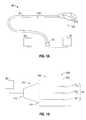
- FIG. 1Ais a schematic diagram of an ablation system according to an embodiment of the present disclosure
- FIG. 1Bis a schematic diagram of an embodiment of the electromagnetic energy delivery device of the ablation system of FIG. 1A in accordance with the present disclosure shown with an energy applicator array;
- FIG. 2is a perspective view with parts disassembled of a portion of an energy applicator according to an embodiment of the present disclosure
- FIG. 4is a perspective view of the portion of the energy applicator of FIG. 3 shown with an electrically-conductive layer disposed about a portion of the dielectric layer according to an embodiment of the present disclosure
- FIG. 5is a perspective view of the portion of the energy applicator of FIG. 4 shown with an electrically-conductive cylinder disposed about the distal end of the electrically-conductive layer according to an embodiment of the present disclosure
- FIG. 6is a perspective view of the portion of the energy applicator of FIG. 3 shown with another embodiment of an electrically-conductive layer and an electrically-conductive cylinder in accordance with the present disclosure
- FIG. 7is an enlarged view of the indicated area of detail of FIG. 6 according to an embodiment of the present disclosure.
- FIG. 9is a perspective view of a portion of an energy delivery device that includes an array of energy applicators, such as the energy applicator of FIG. 8 , in accordance with the present disclosure
- FIG. 10is a perspective view of the portion of the energy delivery device of FIG. 9 shown with a cooling chamber according to an embodiment of the present disclosure
- FIG. 12is a perspective view of the portion of the energy applicator of FIG. 8 shown with a fluid inflow tube and a fluid outflow tube according to an embodiment of the present disclosure
- FIG. 13is an enlarged view of the indicated area of detail of FIG. 12 according to an embodiment of the present disclosure.
- FIG. 14is a perspective view of a portion of an electromagnetic energy delivery device with an array of three energy applicators, such as the energy applicator of FIG. 12 , in accordance with the present disclosure;
- FIG. 15is a perspective view of the portion of the electromagnetic energy delivery device of FIG. 14 shown with a cooling chamber and a material disposed thereabout according to an embodiment of the present disclosure
- FIG. 16shows a diagram of a microwave ablation system that includes a user interface for displaying and controlling ablation patterns in accordance with the present disclosure
- FIG. 18is a diagrammatic representation of a radiation pattern of electromagnetic energy delivered into tissue by an electromagnetic energy delivery device, such as the electromagnetic energy delivery device of FIG. 11 , according to an embodiment of the present disclosure
- FIG. 19is a schematic diagram of an electrosurgical system for treating tissue according to an embodiment of the present disclosure.
- FIG. 21is a schematic diagram of an electrosurgical system for treating tissue, according to an embodiment of the present disclosure.
- FIG. 22is a flowchart illustrating a method of manufacturing an electromagnetic energy delivery device according to an embodiment of the present disclosure.
- proximalrefers to that portion of the apparatus that is closer to the user and the term “distal” refers to that portion of the apparatus that is farther from the user.
- a phrase in the form “A/B”means A or B.
- a phrase in the form “A and/or B”means “(A), (B), or (A and B)”.
- a phrase in the form “at least one of A, B, or C”means “(A), (B), (C), (A and B), (A and C), (B and C), or (A, B and C)”.
- Electromagnetic energyis generally classified by increasing energy or decreasing wavelength into radio waves, microwaves, infrared, visible light, ultraviolet, X-rays and gamma-rays.
- microwavegenerally refers to electromagnetic waves in the frequency range of 300 megahertz (MHz) (3 ⁇ 10 8 cycles/second) to 300 gigahertz (GHz) (3 ⁇ 10 11 cycles/second).
- ablation proceduregenerally refers to any ablation procedure, such as microwave ablation, radio frequency (RF) ablation or microwave ablation assisted resection.
- transmission linegenerally refers to any transmission medium that can be used for the propagation of signals from one point to another.
- Embodiments of the present disclosureprovide electromagnetic energy delivery devices for treating tissue and methods of directing electromagnetic radiation to tissue.
- Embodimentsmay be implemented using electromagnetic radiation at microwave frequencies or at other frequencies.
- An electromagnetic energy delivery device including an energy applicator array, according to various embodiments,is designed and configured to operate between about 500 MHz and about 10 GHz with a directional radiation pattern.
- Various embodiments of the presently disclosed electromagnetic energy delivery device including an energy applicator arrayare suitable for microwave ablation and for use to pre-coagulate tissue for microwave ablation assisted surgical resection.
- various methods described hereinbeloware targeted toward microwave ablation and the complete destruction of target tissue, it is to be understood that methods for directing electromagnetic radiation may be used with other therapies in which the target tissue is partially destroyed or damaged, such as, for example, to prevent the conduction of electrical impulses within heart tissue.
- the teachings of the present disclosuremay also apply to a monopole, helical, or other suitable type of microwave antenna.
- FIG. 1Ashows an electrosurgical system 10 , according to an embodiment of the present disclosure that includes an electromagnetic energy delivery device or ablation array assembly 100 .
- Ablation array assembly 100which is described in more detail later in this disclosure, generally includes an energy applicator array 810 having a radiating portion connected by a feedline 110 (or shaft) via a transmission line 15 to a connector 16 , which may further operably connect the ablation array assembly 100 to a power generating source or generator assembly 28 , e.g., a microwave or RF electrosurgical generator.
- a power generating source or generator assembly 28e.g., a microwave or RF electrosurgical generator.
- Feedline 110may be formed from a suitable flexible, semi-rigid or rigid microwave conductive cable and may connect directly to an electrosurgical power generating source 28 . Alternatively, the feedline 110 may electrically connect the energy applicator array 810 via the transmission line 15 to the electrosurgical power generating source 28 . Feedline 110 may have a variable length from a proximal end of the energy applicator array 810 to a distal end of transmission line 15 ranging from a length of about one inch to about twelve inches. Feedline 110 may be formed of suitable electrically-conductive materials, e.g., copper, gold, silver or other conductive metals or metal alloys having similar conductivity values.
- suitable electrically-conductive materialse.g., copper, gold, silver or other conductive metals or metal alloys having similar conductivity values.
- Feedline 110may be made of stainless steel, which generally offers the strength required to puncture tissue and/or skin. Conductive materials used to form the feedline 110 may be plated with other materials, e.g., other conductive materials, such as gold or silver, to improve their properties, e.g., to improve conductivity, decrease energy loss, etc. In some embodiments, the feedline 110 includes stainless steel, and to improve the conductivity thereof, the stainless steel may be coated with a layer of a conductive material such as copper or gold. Feedline 110 may include an inner conductor, a dielectric material coaxially surrounding the inner conductor, and an outer conductor coaxially surrounding the dielectric material. Feedline 110 may be cooled by fluid e.g., saline or water, to improve power handling, and may include a stainless steel catheter.
- fluide.g., saline or water
- the power generating source 28is configured to provide microwave energy at an operational frequency from about 500 MHz to about 2500 MHz. In other embodiments, the power generating source 28 is configured to provide microwave energy at an operational frequency from about 500 MHz to about 10 GHz. Power generating source 28 may be configured to provide various frequencies of electromagnetic energy. An embodiment of a power generating source, such as the generator assembly 28 of FIG. 1A , in accordance with the present disclosure, is shown in more detail in FIG. 16 . Transmission line 15 may additionally, or alternatively, provide a conduit (not shown) configured to provide coolant fluid from a coolant source 18 to one or more components of the ablation array assembly 100 .
- the ablation array assembly 100may be provided with a coolant chamber (e.g., 1060 shown in FIG. 10 ). Additionally, the ablation array assembly 100 may include coolant inflow and outflow ports (not shown) to facilitate the flow of coolant into, and out of, the coolant chamber. Examples of coolant chamber and coolant inflow and outflow port embodiments are disclosed in commonly assigned U.S. patent application Ser. No. 12/401,268 filed on Mar. 10, 2009, entitled “COOLED DIELECTRICALLY BUFFERED MICROWAVE DIPOLE ANTENNA”, and U.S. Pat. No. 7,311,703, entitled “DEVICES AND METHODS FOR COOLING MICROWAVE ANTENNAS”.
- the electromagnetic energy delivery device 100is inserted into or placed adjacent to tissue and microwave energy is supplied thereto.
- Ultrasound or computed tomography (CT) guidancemay be used to accurately guide the ablation array assembly 100 into the area of tissue to be treated.
- Ablation array assembly 100may be placed percutaneously or surgically, e.g., using conventional surgical techniques by surgical staff.
- a clinicianmay pre-determine the length of time that microwave energy is to be applied.
- Application durationmay depend on many factors such as tumor size and location and whether the tumor was a secondary or primary cancer.
- the duration of microwave energy application using the ablation array assembly 100may depend on the progress of the heat distribution within the tissue area that is to be destroyed and/or the surrounding tissue.
- Single or multiple electromagnetic energy delivery devices 100may provide ablations in short procedure times, e.g., a few minutes, to destroy cancerous cells in the target tissue region.
- a plurality of electromagnetic energy delivery devices 100may be placed in variously-arranged configurations to substantially simultaneously ablate a target tissue region, making faster procedures possible. Multiple electromagnetic energy delivery devices 100 can be used to synergistically create a large ablation or to ablate separate sites simultaneously. Tissue ablation size and geometry is influenced by a variety of factors, such as the energy applicator design, number of energy applicators used simultaneously, ablation time and wattage, and tissue characteristics.
- FIG. 1Bschematically shows an embodiment of the electromagnetic energy delivery device 100 of the electrosurgical system 10 of FIG. 1A that includes an applicator array assembly 150 , a generator assembly 28 that supplies power having a selected phase, amplitude and frequency, and a power divider unit 140 electrically coupled to the generator assembly 28 that divides power into the applicator array assembly 150 .
- Power divider unit 140generally divides power into a plurality of energy applicators (e.g., 270 A, 2708 , 270 C shown in FIG. 19 ) of the applicator array assembly 150 .
- the applicator array assembly 150 and the power divider unit 140are integrally formed.
- the applicator array assembly 150includes a shell assembly 155 and an applicator array “A” that may include any “N” number of energy applicators (e.g., “A 1 ”, “A 2 ” . . . “A N ”), and may include a cooling chamber (e.g., 1060 shown in FIG. 10 ). Because of constructive interference of electric fields at the intended focus and destructive interference of electric fields away from the focus, geometrically-focused energy deposition from multiple electric fields emitted from the applicator array assembly 150 , according to embodiments of the present disclosure, may improve localization of the absorbed energy in targeted tissue and focus heat reliably.
- an applicator array “A”may include any “N” number of energy applicators (e.g., “A 1 ”, “A 2 ” . . . “A N ”), and may include a cooling chamber (e.g., 1060 shown in FIG. 10 ). Because of constructive interference of electric fields at the intended focus and destructive interference of electric fields away from the focus, geometric
- a generator assembly(e.g., 28 shown in FIG. 1B ) includes a processor (e.g., 82 shown in FIG. 17 ) that is operably coupled to one or more phase monitor units (e.g., 447 A, 447 B, 447 C shown in FIG. 21 ) of the power divider unit 140 .
- Power divider unit 140may be a power splitter configured to split an input signal from the generator assembly 28 into two or more equal phase output signals, such as a Wilkinson power splitter.
- Power divider unit 140may be implemented by any suitable power divider that provides equal or unequal power split at the output ports of the power divider unit 140 .
- Power divider unit 140may maintain phase and/or amplitude balance.
- the power divider unit 140may be implemented using a 2-way power divider that provides equal or unequal power split at its output ports while maintaining a phase balance of ⁇ +/ ⁇ 45 degrees. Examples of power divider embodiments are disclosed in commonly assigned U.S. patent application Ser. No. 12/562,842 filed on Sept. 18, 2009, entitled “TISSUE ABLATION SYSTEM WITH ENERGY DISTRIBUTION”.
- the power divider unit 140may include a controller (e.g., 330 shown in FIG. 20 ).
- Power divider unit 140may deliver microwave power to particular channels individually or any combination of one or more channels equally or unequally to facilitate selective activation of energy delivery to particular channels or combination of channels. For example, a user may select channels to which energy is delivered. In this scenario, if the second and third channels are selected, energy delivery may be divided equally between the second and third channels and, thus, unequally between the first channel and the second and third channels since no energy is delivered to the first channel in this scenario. Further, in this scenario, energy may be delivered to individual channels according to selected time intervals by dynamically changing the channels to which energy is delivered. For example, energy may be delivered to the first channel at a time interval, t 1 .
- the power divider unit 140may divide energy between the energy applicators (e.g., “A i ”, “A 2 ”, “A N ” shown in FIG. 1B ) to tailor the size and shape of ablation lesions.
- Applicator array assembly 150includes a plurality of input ports (not shown) connectable to any one or more output ports (not shown) of the power divider unit 140 , and may be disposed substantially adjacent to a distal end portion 141 of the power divider unit 140 .
- a handle assembly(not shown) may be attached to the proximal end portion 142 of the power divider unit 140 , and may be coaxially-disposed around at least a portion of the feedline 110 .
- the shape and size of the power divider unit 140 and the applicator array assembly 150may be varied from the configuration depicted in FIG. 1B .
- FIGS. 2 through 8show a sequentially-illustrated, assembly of components forming an energy applicator, shown generally as 800 in FIG. 8 , in accordance with the present disclosure.
- a coaxial feedline 226is shown with the outer conductor 224 trimmed back, such that a portion 221 of the dielectric material 222 and the inner conductor 220 extends beyond the outer conductor 224 .
- an energy applicator segment(shown generally as 200 in FIG. 2 ) includes an electrically-conductive element 260 that extends along the longitudinal axis “A” of the energy applicator segment 200 . Electrically-conductive element 260 may be positioned in a distal portion of the energy applicator 800 .
- the electrically-conductive member 260is a solid metal cylinder disposed at the distal end of the portion 221 electrically coupled to the inner conductor 220 (e.g., by solder).
- Electrically-conductive element 260may be formed of any suitable electrically-conductive material (e.g., metal such as stainless steel, aluminum, titanium, copper, etc.) of any suitable length. The shape and size of the electrically-conductive element 260 may be varied from the configuration depicted in FIG. 2 .
- FIG. 3shows an energy applicator segment 300 according to an embodiment of the present disclosure that is similar to the energy applicator segment 200 of FIG. 2 , except for a dielectric layer 322 (also referred to herein as a balun insulator) disposed coaxially about a distal portion of the outer conductor 224 of the feedline 226 .
- Dielectric layer 322may have a suitable length “L 1 ” in a range of about 0.1 inches to about 3.0 inches. Dielectric layer 322 may be spaced apart from and disposed proximal to the distal end of the outer conductor 224 .
- the dielectric layer 322is spaced apart, by a length “L 2 ”, e.g., about 0.1 inches, from the distal end of the outer conductor 224 .
- Balun insulator 322may extend distally beyond the distal end of the conductive balun sleeve (e.g., 430 shown in FIG. 4 ) to direct current into a balancing/unbalancing (balun) structure (e.g., “B” shown in FIG. 4 ).
- Dielectric layer 322may be formed of any suitable insulative material, including, but not limited to, ceramics, water, mica, polyethylene, polyethylene terephthalate, polyimide, polytetrafluoroethylene (PTFE) (e.g., Teflon®, manufactured by E. I. du Pont de Nemours and Company of Wilmington, Del., United States), glass, metal oxides or other suitable insulator, and may be formed in any suitable manner. Dielectric layer 322 may be grown, deposited or formed by any other suitable technique. In some embodiments, the balun insulator 322 is formed from a material with a dielectric constant in the range of about 1.7 to about 10. The shape, size and relative position of the balun insulator 322 may be varied from the configuration depicted in FIG. 3 .
- FIG. 4shows an energy applicator segment 400 according to an embodiment of the present disclosure that is similar to the energy applicator segment 300 of FIG. 3 except for an electrically-conductive layer 430 (also referred to herein as a conductive balun sleeve) disposed coaxially about a proximal portion of the energy applicator segment 400 .
- Electrically-conductive layer 430may have any suitable length “L 3 ”, e.g., about 0.1 inches to about 3.0 inches. Electrically-conductive layer 430 may be formed as a single structure and electrically coupled to the outer conductor 224 , e.g., by solder or other suitable electrical connection.
- the electrically-conductive layer 430includes a first portion 431 , having a length “L 5 ”, disposed coaxially about a proximal portion of the dielectric layer 322 , and a second portion 432 , having a length “L 4 ”, disposed proximally to the first portion 431 electrically coupled to the outer conductor 224 .
- First and second portions 431 , 432may be formed of any suitable electrically-conductive material, e.g., metal such as stainless steel, titanium, copper, etc., and may be formed in any suitable manner.
- First and second portions 431 , 432may be formed separately from each other.
- First and second portions 431 , 432may form a single, unitary structure.
- the shape and size of the electrically-conductive balun sleeve 430may be varied from the configuration depicted in FIG. 4 .
- FIG. 5shows an energy applicator segment 500 according to an embodiment of the present disclosure that is similar to the energy applicator segment 400 of FIG. 4 , except for an electrically-conductive cylinder 540 disposed coaxially about a distal portion of the electrically-conductive layer 430 .
- Electrically-conductive cylinder 540may have a suitable length “L 6 ” in a range of about 0.05 inches to about 0.2 inches.
- the distal edge of electrically-conductive cylinder 540is disposed overlying the distal edge of the electrically-conductive layer 430 .
- the shape and size of the electrically-conductive cylinder 540may be varied from the configuration depicted in FIG. 5 .
- FIG. 6shows an energy applicator segment 600 according to an embodiment of the present disclosure that includes an electrically-conductive layer 630 and an electrically-conductive cylinder 640 .
- Electrically-conductive layer 630surrounds a proximal portion of the dielectric layer 322 and is electrically coupled to the outer conductor 224 , e.g., by solder or other suitable electrical connection.
- Electrically-conductive layer 630is similar to the electrically-conductive layer 430 of FIG. 4 , except that the electrically-conductive layer 630 has a length that is less than the length “L 3 ” of the electrically-conductive layer 430 .
- the electrically-conductive layer 630may have a length “L 7 ”, which is shorter than the length “L 3 ” by a length “L 9 ”.
- Electrically-conductive cylinder 640 shown in FIGS. 6 and 7is similar to the electrically-conductive cylinder 540 of FIG. 5 , except that the electrically-conductive cylinder 640 extends distally beyond the distal edge of the electrically-conductive layer 630 .
- the electrically-conductive cylinder 640having a length “L 6 ”, includes a first portion 641 , having a length “L 8 ”, disposed coaxially about the distal end of the electrically-conductive layer 630 , and a second portion 642 , having a length “L 9 ”, disposed distally to the first portion 641 , surrounding a portion of the dielectric layer 322 distally extending beyond the electrically-conductive layer 630 .
- the electrically-conductive cylinder 640is positioned relative to the distal edge of the electrically-conductive layer 630 such that the combined length of the electrically-conductive layer 630 and the electrically-conductive cylinder 640 is a length “L 3 ”, which may be, for example, a quarter wavelength or a half wavelength.
- L 3may be, for example, a quarter wavelength or a half wavelength.
- the shape and size of the electrically-conductive cylinder 640may be varied from the configuration depicted in FIGS. 6 and 7 .
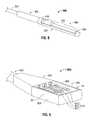
- FIG. 8shows an energy applicator segment 800 according to an embodiment of the present disclosure that is similar to the energy applicator segment 500 of FIG. 5 , except for a generally longitudinally-disposed dielectric structure 850 .
- the dielectric structure 850includes a dielectric cap configured to cover the distal end of the electrically-conductive member 260 .
- the dielectric structure 850may be disposed distally to the electrically-conductive cylinder 540 .
- Dielectric structure 850may be formed using over-molding techniques or other forming techniques.
- the dielectric structure 850is formed from a material with a dielectric constant in the range of about 1.7 to about 10. The shape and size of the dielectric structure 850 may be varied from the configuration depicted in FIG. 8 .
- the dielectric structure 850includes a first dielectric segment 851 , a second dielectric segment 852 , and a third dielectric segment 853 .
- the first dielectric segment 851extends distally from the distal end of the electrically-conductive cylinder 540 and may have a substantially half-cylindrical shape.
- First dielectric segment 851may be made to encompass any radial angle.
- the fist dielectric segment 851extends from the distal end of the electrically-conductive cylinder 540 to distal end of the electrically-conductive member 260 .
- Second dielectric segment 852is configured to cover the distal end of the electrically-conductive member 260 , and may include a first portion and a second portion. In some embodiments, the first and second dielectric segments 851 , 852 are integrally formed in a molding process. First dielectric segment 851 , the second dielectric segment 852 and the third dielectric segment 853 may be formed by any suitable process.
- the energy applicator segment 800may be provided with an outer jacket (not shown) disposed about the electrically-conductive layer 430 , the electrically-conductive cylinder 540 and/or the dielectric structure 850 .
- the outer jacketmay be formed of any suitable material, such as, for example, polymeric or ceramic materials.
- the outer jacketmay be applied by any suitable method, such as, for example, heat shrinking, over-molding, coating, spraying dipping, powder coating, baking and/or film deposition.
- the outer jacketmay be a water-cooled catheter formed of a material having low electrical conductivity.
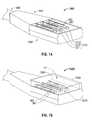
- FIG. 9shows a portion or unit 1100 A of an electromagnetic energy delivery device, such the electromagnetic energy delivery device 1200 of FIG. 11 , with an array of three energy applicators, such as the energy applicator 800 of FIG. 8 , in accordance with the present disclosure.
- the portion 1100 Aincludes an applicator array assembly 950 , a power divider unit 940 electrically coupleable to a generator assembly (e.g., 28 shown in FIG. 16 ) for dividing power for a plurality of channels (e.g., 450 A, 450 B and 450 C shown in FIG. 21 ) connected to the applicator array assembly 950 , and a handle member 930 .
- Power divider unit 940is similar to the power divider unit 140 of FIG. 1B and further description thereof is omitted in the interests of brevity.
- the applicator array assembly 950includes a shell assembly 953 and an applicator array 810 including three energy applicators 811 , 812 and 813 .
- the shell assembly 953has a substantially rectangular shape, and may extend distally beyond the length of the radiating portion of the applicator array 810 .
- the shape and size of the shell assembly 953may be varied from the configuration depicted in FIG. 9 .
- the shell assembly 953has a substantially oblong shape.
- the portion 1100 A of the electromagnetic energy delivery device illustrated in FIG. 9includes three energy applicators 811 , 812 and 813 , it is to be understood that any “N” number of energy applicators may be utilized.
- Shell assembly 953may include an outer portion 951 and an inner portion 952 .
- the outer portion 951 of the shell assembly 953is formed of an electrically-conductive material e.g., stainless steel, and electrically coupled to the distal end of the conductive balun sleeve (e.g., 430 shown in FIG. 4 ) of one or more of the energy applicators 811 , 812 and 813 .
- Inner portion 952 of the shell assembly 953may be formed of any suitable dielectric material. A distal portion of the inner portion 952 may extend distal to the distal ends of the energy applicators 811 , 812 and 813 .
- Outer portion 951may include any electrically-conductive material, such as, for example, copper, stainless steel, titanium, titanium alloys such as nickel-titanium and titanium-aluminum-vanadium alloys, aluminum, aluminum alloys, tungsten carbide alloys or combinations thereof. Portions of the outer portion 951 may be loaded with low- to mid-range permittivity dielectric materials to aid in radiation directivity and impedance matching. Several shells, or other shapes, of different dielectric materials may nest together to form the outer portion 951 .
- Inner portion 952may include a dielectric material.
- the inner portion 952includes dielectric material layers.
- the inner portion 952may include one or more thin layers, one or more thick layers or a mixture of thick and thin layers.
- Inner portion 952may be composed of any suitable dielectric material which may be the same as, or different from, the dielectric material, if any, used in the outer portion 951 .
- the dielectric materials used to form the inner portion 952may vary in dielectric constant with shells or more complex dielectric layering to achieve the optimum antenna directivity and energy to tissue delivery.
- a portion of the cap of dielectric material 852 and a portion of the first dielectric segment 851 of one or more of the energy applicators 811 , 812 and 813are disposed in a recess in the form of a groove (not shown) defined in the planar top surface “S” of the inner portion 952 .
- the inner portion 952 , or portions thereof,may be adapted to circulate coolant fluid therethrough.
- FIG. 10shows a portion 1100 B of an electromagnetic energy delivery device according to an embodiment of the present disclosure that is similar to the portion 1100 A of FIG. 9 , except for a chamber 1060 (also referred to herein as a cooling chamber).
- Chamber 1060generally includes a fluid inlet port (not shown) and a fluid outlet port (not shown).
- Coolant chamber 1060is adapted to circulate coolant fluid (e.g., “F” shown in FIG. 11 ) therethrough, and may include baffles, multiple lumens, flow restricting devices, or other structures that may redirect, concentrate, or disperse flow depending on their shape.
- coolant fluide.g., “F” shown in FIG. 11
- FIG. 11shows an embodiment of an electromagnetic energy delivery device 1200 in accordance with the present disclosure that includes the portion 1100 B of FIG. 10 shown with a material 1180 disposed about the cooling chamber 1060 thereof.
- Material 1180may include any suitable material. Suitable materials for use as the material 1180 may include high dielectric-constant materials, such as, for example, inorganic nonmetallic materials (e.g., ceramics), metallic oxides (e.g., alumina, titanium dioxide, zirconium dioxide, or zinc oxide) and combinations thereof.
- Material 1180may include a nonconductive radio frequency transparent material, e.g., a glass fiber epoxy composite polyimide, high temperature conformable rubber or plastic. Material 1180 may be formed using over-molding techniques or other forming techniques.
- FIG. 12shows an energy applicator segment 900 according to an embodiment of the present disclosure that is similar to the energy applicator segment 800 of FIG. 8 , except for a longitudinally-extending inflow tube 961 , a longitudinally-extending outflow tube 962 , and an electrically-conductive cylinder 1240 having a notch “N” defined therein that is configured to receive the inflow and outflow tubes 961 , 962 .
- the inflow and outflow tubes 961 , 962are configured to supply and/or dispense coolant fluid (e.g., saline, water or other suitable coolant fluid) into and out of a distal portion of a cooling chamber (e.g., 1560 shown in FIG. 15 ).
- coolant fluide.g., saline, water or other suitable coolant fluid
- a pumpmay be connected in fluid communication between the cooling chamber and a coolant source (e.g., 18 shown in FIG. 1A ).
- Inflow and outflow tubes 961 , 962may include thin-walled polyimide tubes.
- a pumpsupplies coolant fluid from a coolant source to one or more inflow tubes 961 which, in turn, deliver coolant fluid to the cooling chamber (e.g., 1560 shown in FIG. 15 ).
- a pumpmay be fluidly coupled to one or more outflow tubes 962 to draw coolant fluid out of the cooling chamber.
- the inflow and outflow tubes 961 , 962may extend longitudinally across the full length of the electrically-conductive layer 430 and at least partially across the dielectric structure 850 . As shown in FIG. 13 , a portion or segment “S” of the inflow and outflow tubes 961 , 962 is disposed within a notch “N” defined within the electrically-conductive cylinder 1240 . In some embodiments, the notch “N” is configured as a recess, e.g., in the form of a groove or hole.
- the notch “N”is configured as a first recess (not shown) and a second recess (not shown), wherein the first recess is configured to receive one or more inflow tubes 961 and the second recess is configured to receive one or more outflow tubes 962 .
- Inflow tube 961 and the outflow tube 962may be formed to have the same diameters or different diameters. Inflow and outflow tubes 961 , 962 may have any suitable length. In some embodiments, the segment “S” of the inflow and outflow tubes 961 , 962 is disposed between the electrically-conductive layer 430 and the outer circumferential surface of the electrically-conductive cylinder 1240 , which helps minimize the outer diameter of the energy applicator. Inflow and outflow tubes 961 , 962 may be held in place, e.g., along the electrically-conductive layer 430 and/or within the notch “N”, by using UV adhesive or other similar suitable adhesives, as well as heat shrink tubing or by other suitable methods. The shape and size of the inflow and outflow tubes 961 , 962 , the electrically-conductive cylinder 1240 and the notch “N” may be varied from the configurations depicted in FIGS. 12 and 13 .
- FIG. 14shows a portion 1400 , of an electromagnetic energy delivery device that is similar to the portion 1100 A of the electromagnetic energy delivery device of FIG. 9 .
- the portion 1400includes an applicator array assembly 1450 , a power divider unit 940 electrically coupleable to a generator assembly (e.g., 28 shown in FIG. 16 ) for dividing power for a plurality of channels connected to the applicator array assembly 1450 , and a handle member 930 .
- Power divider unit 940is similar to the power divider unit 140 of FIG. 1B and further description thereof is omitted in the interests of brevity.
- Applicator array assembly 1450is similar to the applicator array assembly 950 shown in FIG.
- the inflow and outflow tubes 961 , 962are configured to supply and/or dispense coolant fluid “F” (e.g., saline, water or other suitable coolant fluid) into and out of a cooling chamber (e.g., 1560 shown in FIG. 15 ).
- coolant fluid “F”e.g., saline, water or other suitable coolant fluid
- FIG. 15shows an embodiment of an electromagnetic energy delivery device 1500 in accordance with the present disclosure that includes the portion 1400 of FIG. 14 shown with a cooling chamber 1560 and a material 1580 disposed thereabout.
- Cooling chamber 1560at least partially surrounds the energy applicator array 1210 including three energy applicators 1211 , 1212 and 1213 ( FIG. 14 ).
- the shape and size of the inflow and outflow tubes 961 , 962 and the chamber 1560may be varied from the configuration depicted in FIG. 15 .
- portions of the inflow and outflow tubes 961 , 962are disposed within the chamber 1560 .
- the chamber 1560may include a material having a high dielectric constant, such as alumina, titanium dioxide or zirconium dioxide, for improved antenna directivity and energy to tissue delivery efficiency. Cooling chamber 1560 and the material 1580 disposed thereabout are similar to the chamber 1060 and the material 1080 shown in FIGS. 10 and 11 , respectively, and further description thereof is omitted in the interests of brevity.
- a material having a high dielectric constantsuch as alumina, titanium dioxide or zirconium dioxide
- FIG. 16schematically illustrates an electrosurgical system 1000 in accordance with an embodiment of the present disclosure.
- Electrosurgical system 1000includes an actuator 20 operably coupled by a cable 19 via connector 17 to an embodiment of the generator assembly 28 of the electrosurgical system 10 of FIG. 1A .
- Actuator 20may be a footswitch, a handswitch, a bite-activated switch, or any other suitable actuator.
- Cable 19may include one or more electrical conductors for conveying an actuation signal from the actuator 20 to the generator assembly 28 .
- the actuator 20is operably coupled to the generator assembly 28 by a wireless link, such as without limitation, a radiofrequency or infrared link.
- the clinicianmay interact with the user interface 25 to preview operational characteristics of the electromagnetic energy delivery device 100 .
- Generator assembly 28includes a generator module (e.g., 86 shown in FIG. 17 ) in operable communication with a processor (e.g., 82 shown in FIG. 17 ), a user interface 25 , and an actuator 20 .
- Electromagnetic energy delivery device 100is operably coupled to an energy output of the generator module, which may be configured as a source of RF and/or microwave energy.
- Actuator 20is operably coupled to the processor 82 via user interface 25 .
- actuator 20may be operably coupled to the processor and/or to the generator module by a cable connection, or a wireless connection.
- User interface 25may include a display 21 , such as without limitation a flat panel graphic LCD (liquid crystal display), adapted to visually display at least one user interface element 23 , 24 .
- display 21includes touchscreen capability (not shown), e.g., the ability to receive input from an object in physical contact with the display, such as without limitation, a stylus or a user's fingertip.
- a user interface element 23 , 24may have a corresponding active region, such that, by touching the screen within the active region associated with the user interface element, an input associated with the user interface element 23 , 24 is received by the user interface 25 .
- User interface 25may additionally, or alternatively, include one or more controls 22 that may include without limitation a switch (e.g., pushbutton switch, toggle switch, slide switch) and/or a continuous actuator (e.g., rotary or linear potentiometer, rotary or linear encoder.)
- a control 22has a dedicated function, e.g., display contrast, power on/off, and the like.
- Control 22may also have a function that may vary in accordance with an operational mode of the electrosurgical system 10 .
- a user interface element 23may be positioned substantially adjacently to control 22 to indicate the function thereof.
- Control 22may also include an indicator, such as an illuminated indicator (e.g., a single- or variably-colored LED indicator.)
- FIG. 17is a block diagram showing one embodiment of the electrosurgical system 1000 of FIG. 16 .
- the generator module 86is configured to provide energy of about 915 MHz.
- Generator module 86may additionally, or alternatively, be configured to provide energy of about 2450 MHz (2.45 GHz).
- the present disclosurecontemplates embodiments wherein the generator module 86 is configured to generate a frequency other than about 915 MHz or about 2450 MHz, and embodiments wherein the generator module 86 is configured to generate variable frequency energy.
- Generator assembly 28includes a processor 82 that is operably coupled to user interface 21 .
- Processor 82may include any type of computing device, computational circuit, or any type of processor or processing circuit capable of executing a series of instructions that are stored in a memory, e.g., storage device 88 or external device 91 .
- a storage device 88is operably coupled to the processor 82 , and may include random-access memory (RAM), read-only memory (ROM), and/or non-volatile memory (NV-RAM, Flash, and disc-based storage.)
- Storage device 88may include a set of program instructions executable on the processor 82 for executing a method for displaying and controlling ablation patterns in accordance with the present disclosure.
- Generator assembly 28may include a data interface 90 that is configured to provide a communications link to an external device 91 .
- the data interface 90may be any of a USB interface, a memory card slot (e.g., SD slot), and/or a network interface (e.g., 100BaseT Ethernet interface or an 802.11 “Wi-Fi” interface.)
- External device 91may be any of a USB device (e.g., a memory stick), a memory card (e.g., an SD card), and/or a network-connected device (e.g., computer or server).
- Generator assembly 28may also include a database 84 that is configured to store and retrieve energy applicator data, e.g., parameters associated with one or energy applicators (e.g., “A 1 ”, “A 2 ”, “A N ” shown in FIG. 1B ) and/or one or more applicator array assemblies (e.g., 150 shown in FIG. 1B ).
- Parameters stored in the database 84 in connection with an applicator array assemblymay include, but are not limited to, applicator array assembly identifier, applicator array assembly dimensions, a frequency, an ablation length, an ablation diameter, a temporal coefficient, a shape metric, and/or a frequency metric.
- ablation pattern topologymay be included in the database 84 , e.g., a wireframe model of an applicator array assembly (e.g., 150 shown in FIG. 1B ) and/or an ablation pattern associated therewith.
- Database 84may also be maintained at least in part by data provided by the external device 91 via the data interface 90 .
- energy applicator datamay be uploaded from an external device 91 to the database 84 via the data interface 90 .
- Energy applicator datamay additionally, or alternatively, be manipulated, e.g., added, modified, or deleted, in accordance with data and/or instructions stored on the external device 91 .
- the set of energy applicator data represented in the database 84is automatically synchronized with corresponding data contained in external device 91 in response to external device 91 being coupled (e.g., physical coupling and/or logical coupling) to data interface 90 .
- Processor 82is programmed to enable a user, via user interface 25 and/or display 21 , to view at least one ablation pattern and/or other energy applicator data corresponding to an embodiment of an applicator array assembly. For example, a surgeon may determine that a substantially spherical ablation pattern is necessary. The surgeon may activate a “select ablation shape” mode of operation for generator assembly 28 , preview an energy applicator array by reviewing graphically and textually presented data on display 21 , optionally, or alternatively, manipulate a graphic image by, for example, rotating the image, and to select an array of energy applicators based upon displayed parameters. The selected energy applicator(s) may then be electrically coupled to the generator assembly 28 for use therewith.
- a surgeonmay input via user interface 25 an applicator array parameter to cause generator assembly 28 to present one or more electromagnetic energy delivery devices corresponding thereto. For example, a surgeon may require a 3.0 cm ⁇ 3.0 cm ablation pattern, and provide an input corresponding thereto.
- the generator assembly 28may preview a corresponding subset of available electromagnetic energy delivery devices 100 that match or correlate to the inputted parameter.
- FIG. 18is a diagrammatic representation of a radiation pattern “R” of electromagnetic energy delivered into tissue “T” by an electromagnetic energy delivery device, such as the electromagnetic energy delivery device 1200 of FIG. 11 , according to an embodiment of the present disclosure.
- FIG. 19is a schematic diagram of an electrosurgical system 2000 for treating tissue according to an embodiment of the present disclosure.
- Electrosurgical system 2000includes a microwave signal source 210 providing a microwave frequency output signal to a microwave amplifier unit 230 , a phase-balanced microwave power splitter 240 coupled to the microwave amplifier unit 230 , and a first, a second and a third microwave ablation antenna assembly 270 A, 270 B and 270 C, each coupled to the phase-balanced microwave power splitter 240 .
- the microwave signal source 210is capable of generating a plurality of output signals of various frequencies that are input to the microwave amplifier unit 230 .
- the microwave amplifier unit 230may have any suitable input power and output power.
- a first transmission line 250 Aelectrically connects the first antenna assembly 270 A to the phase-balanced microwave power splitter 240 , defining a first channel
- a second transmission line 250 Belectrically connects the second antenna assembly 270 B to the phase-balanced microwave power splitter 240 , defining a second channel
- a third transmission line 250 Celectrically connects the third antenna assembly 270 C to the phase-balanced microwave power splitter 240 , defining a third channel.
- the first, second and third transmission lines 250 A, 250 B and 250 Cmay each include one or more electrically conductive elements, such as electrically conductive wires.
- the first, second and third transmission lines 250 A, 250 B and 250 Ceach have substantially the same length, which preserves the phase relationship between the electrical signals in each channel of the electrosurgical system 2000 .
- the phase-balanced microwave power splitter 240may be implemented by any suitable power divider that provides equal power split at all output ports while substantially maintaining phase.
- the phase-balanced microwave power splitter 240may be implemented using a 3-way power divider that provides equal power split at all output ports while maintaining a phase balance of ⁇ +/ ⁇ 45 degrees.
- the phase-balanced microwave power splitter 240may be implemented by any suitable power divider that provides equal power split at all output ports while substantially maintaining phase and amplitude balance.
- the phase-balanced microwave power splitter 240implements using a 3-way power divider that provides equal power split at all output ports while maintaining a phase balance of ⁇ +/ ⁇ 10 degrees and amplitude balance of ⁇ 1.5 dB.
- Each antenna assembly 270 A, 270 B and 270 Ctypically includes a plurality of electrodes disposed on a rigid or bendable needle or needle-like structure.
- the antenna assemblies 270 A, 270 B and 270 Care positioned substantially parallel to each other, for example, spaced about 5 millimeters (mm) apart, and inserted directly into tissue or placed into the body during surgery by a clinician, or positioned in the body by other suitable methods.
- mmmillimeters
- microwave ablation antenna assemblies 270 A, 270 B and 270 Cinclude three microwave ablation antenna assemblies 270 A, 270 B and 270 C, it is to be understood that any “N” number of antenna assemblies may be utilized and that phase-balanced microwave power splitter 240 may be implemented by any suitable power divider that divides or splits a microwave input signal into “N” number of output signals of equal power while substantially maintaining phase and amplitude balance.
- the electrosurgical system 2000delivers phase-controlled microwave power to each antenna assembly 270 A, 270 B and 270 C of the three-channel system.
- the electrosurgical system 2000delivers substantially in-phase microwave power to each antenna assembly 270 A, 2708 and 270 C, which may result in a more efficient ablating tool than out-of-phase energy applicators.
- a desired effect on tissue between the energy applicatorsis produced.
- energy applicators that are 180 degrees out of phase with respect to each otherproduce a desired effect on tissue.
- the electrosurgical system 2000delivers phase-controlled microwave power to each antenna assembly 270 A, 270 B and 270 C while maintaining a phase balance of ⁇ +/ ⁇ 45 degrees.
- the electrosurgical system 2000is implemented with operating frequencies in the range of about 915 MHz to about 5 GHz, which may be useful in performing ablation procedures and/or other procedures. It is to be understood that the electrosurgical system 2000 may be implemented with any appropriate range of operating frequencies.
- FIG. 20is a schematic diagram of an embodiment of an electrosurgical system 3000 for treating tissue according to an embodiment of the present disclosure.
- Electrosurgical system 3000includes a microwave signal source 310 providing a microwave frequency output signal to a controller 330 , and a first, a second and a third microwave ablation antenna assembly 270 A, 270 B and 270 C, each coupled to the controller 330 .
- the microwave signal source 310is capable of generating a plurality of output signals of various frequencies that are input to the controller 330 .
- the controller 330includes a first, a second and a third microwave amplifier 320 A, 320 B and 320 C that are phase-balanced with respect to one another.
- the first, second and third phase-balanced microwave amplifiers 320 A, 320 B and 320 Ceach deliver equal power while maintaining a phase balance of ⁇ +/ ⁇ 10 degrees and amplitude balance of ⁇ 1.5 dB.
- the first, second and third phase-balanced microwave amplifiers 320 A, 320 B and 320 Ceach deliver phase-controlled microwave power to the respective antenna assemblies 270 A, 270 B and 270 C while maintaining a phase balance of ⁇ +/ ⁇ 45 degrees.
- the first, second and third phase-balanced microwave amplifiers 320 A, 320 B and 3200may have any suitable input power and output power.
- a first transmission line 350 Aelectrically connects the first antenna assembly 270 A to the first phase-balanced microwave amplifier 320 A, defining a first channel
- a second transmission line 350 Belectrically connects the second antenna assembly 270 B to the second phase-balanced microwave amplifier 320 B, defining a second channel
- a third transmission line 350 Celectrically connects the third antenna assembly 270 C to the third phase-balanced microwave amplifier 320 C, defining a third channel.
- the first, second and third transmission lines 350 A, 350 B and 350 Ceach include one or more electrically conductive elements, such as electrically conductive wires.
- the first, second and third transmission lines 350 A, 350 B and 350 Ceach have substantially the same length, which preserves the phase relationship between electrical signals in each channel of the electrosurgical system 3000 .
- the electrosurgical system 3000 illustrated in FIG. 20includes three microwave ablation antenna assemblies 270 A, 270 B and 270 C and three phase-balanced microwave amplifiers 320 A, 3208 and 320 C, it is to be understood that any “N” number of antenna assemblies and any “N” number of phase-balanced microwave amplifiers may be utilized.
- FIG. 21is a schematic diagram of an electrosurgical system 4000 for treating tissue according to another embodiment of the present disclosure.
- the disclosed electrosurgical system 4000is a three-channel system that includes a first, a second and a third microwave signal source 410 A, 410 B and 410 C, a first, a second and a third microwave amplifier 420 A, 420 B and 420 C, a controller 440 that includes three inputs 442 A, 442 B and 442 C and three outputs 448 A, 448 B and 448 C, and a first, a second and a third microwave ablation antenna assembly 270 A, 270 B and 270 C.
- the first, second and third microwave signal sources 410 A, 410 B and 410 Cprovide microwave frequency output signals to the first, second and third amplifiers 420 A, 420 B and 420 C, respectively.
- the first microwave amplifier 420 Aprovides an output signal through an output terminal that is electrically coupled to the first input 442 A of the controller 440 ;
- the second microwave amplifier 420 Bprovides an output signal through an output terminal that is electrically coupled to the second input 442 B of the controller 440 ;
- the third microwave amplifier 420 Cprovides an output signal through an output terminal that is electrically coupled to the third input 442 C of the controller 440 .
- the first, second and third amplifiers 420 A, 420 B and 420 Ceach have any suitable input power and output power.
- the first, second and third amplifiers 420 A, 420 B and 420 Cmay be phase-balanced with respect to one another and, in such case, are arranged between the controller 440 and the first, second and third microwave ablation antenna assemblies 270 A, 270 B and 270 C.
- first, second and third amplifiers 420 A, 420 B and 420 Care illustrated as standalone modules in FIG. 21 , it is to be understood that one or more of the amplifiers may be integrated fully or partially into the controller 440 .
- the electrosurgical system 4000may be implemented without the first, second and third amplifiers 420 A, 420 B and 420 C, or with any combination thereof.
- the controller 440includes a first, a second and a third phase shifter 443 A, 443 B and 443 C, and a first, a second and a third phase monitor unit 447 A, 447 B and 447 C.
- the first phase shifter 443 Ais electrically coupled between the first input 442 A and the first phase monitor unit 447 A;
- the second phase shifter 443 Bis electrically coupled between the second input 442 B and the second phase monitor unit 447 B;
- the third phase shifter 443 Cis electrically coupled between the third input 442 C and the third phase monitor unit 447 C.
- the first phase monitor unit 447 Ais electrically coupled between the first phase shifter 443 A and the output 448 A; the second phase monitor unit 447 B is electrically coupled between the second phase shifter 443 B and the output 448 B; and the third phase monitor unit 447 C is electrically coupled between the third phase shifter 443 C and the output 448 C.
- the controller 440may include a number of processing units (not shown) coupled to the first, second and third phase monitor units 447 A, 447 B and 447 C for controlling output of one or more of the phase shifters 443 A, 443 B and 443 C to provide a desired phase relationship of electrical signals in each channel of the electrosurgical system 4000 .
- the processing unit(s)may include multiple processors and/or multicore CPUs and may include any type of processor capable of executing software, such as a microprocessor, digital signal processor, microcontroller, or the like.
- the controller 440may additionally, or alternatively, be operably coupled to an external processor (e.g., 82 shown in FIG. 16 ).
- the controller 440may include one or more phase detectors (not shown) to compare the respective phases of electrical signals inputted through the inputs 442 A, 442 B and/or 442 C. By comparing a reference signal, such as a clock signal, to a feedback signal using a phase detector, phase adjustments may be made based on the comparison of the electrical signals inputted, to set the phase relationship between electrical signals in each channel of the electrosurgical system 4000 .
- phase detectorsnot shown to compare the respective phases of electrical signals inputted through the inputs 442 A, 442 B and/or 442 C.
- the controller 440delivers phase-controlled microwave power through the outputs 448 A, 448 B and 448 C to the antenna assemblies 270 A, 270 B and 270 C, respectively irrespective of the individual phases of each of electrical signals inputted through the inputs 442 A, 442 B and/or 442 C. As illustrated in FIG.
- a first transmission line 450 Aelectrically connects the first antenna assembly 270 A to the output 448 A of the controller 440 , defining a first channel
- a second transmission line 450 Belectrically connects the second antenna assembly 270 B to the output 448 B of the controller 440 , defining a second channel
- a third transmission line 450 Celectrically connects the third antenna assembly 270 C to the output 448 C of the controller 440 , defining a third channel.
- the first, second and third transmission lines 450 A, 450 B and 450 Ceach include one or more electrically conductive elements, such as electrically conductive wires.
- the first, second and third transmission lines 450 A, 450 B and 450 Ceach have substantially the same length, which preserves the phase relationship between electrical signals in each channel of the electrosurgical system 4000 .
- FIG. 22is a flowchart illustrating a method of manufacturing an electromagnetic energy delivery device according to an embodiment of the present disclosure.
- a plurality of coaxial cablesis provided.
- Each coaxial cablee.g., 226 shown in FIG. 2
- includes an inner conductore.g., 220 shown in FIG. 2
- an outer conductore.g., 224 shown in FIG. 2
- a dielectric materiale.g., 222 shown in FIG. 2
- a portion of the inner conductor and the dielectric materialmay extend beyond the outer conductor at the distal end of the coaxial cable.
- a plurality of first applicator segmentsis formed by joining an elongated electrically-conductive member (e.g., 260 shown in FIG. 2 ) to the distal end of the inner conductor (e.g., 220 shown in FIG. 2 ) of each of the plurality of coaxial cables.
- the electrically-conductive memberis a solid metal cylinder electrically coupled to the inner conductor, e.g., by solder or other suitable electrical connection.
- a plurality of second applicator segmentsis formed by joining a balun structure (e.g., “B” shown in FIG. 4 ) to a distal portion of the outer conductor (e.g., 224 shown in FIG. 3 ) of each of the plurality of first applicator segments.
- the balun structuremay be a quarter wavelength sleeve balun.
- the balun structureincludes a balun insulator (e.g., 322 shown in FIG. 3 ) coaxially disposed around a distal portion of the outer conductor, and an electrically-conductive balun sleeve (e.g., 430 shown in FIG.
- balun insulatormay extend distally beyond the distal end of the electrically-conductive balun sleeve to direct currents into the balun.
- a plurality of third applicator segmentsis formed by positioning an electrically-conductive cylinder (e.g., 540 shown in FIG. 5 ) overlying a distal portion of the balun structure of each of the plurality of second applicator segments.
- a portion (e.g., 642 shown in FIG. 7 ) of the electrically-conductive cylinder (e.g., 640 shown in FIGS. 6 and 7 )extends distally beyond the distal edge of an electrically-conductive balun sleeve (e.g., 630 shown in FIG. 7 ) of the balun.
- the electrically-conductive cylinderis positioned relative to the distal edge of the electrically-conductive balun sleeve such that the combined length of the conductive balun sleeve and the conductive cylinder is a quarter wavelength or a half wavelength.
- a plurality of energy applicatorsis formed by forming a dielectric structure (e.g., 850 shown in FIG. 8 ) having a proximal end disposed substantially adjacent to a distal end of the electrically-conductive cylinder of each of the plurality of third applicator segments, wherein each dielectric structure longitudinally extends from the distal end of the electrically-conductive cylinder to a distal end of the electrically-conductive member.
- the dielectric structureincludes a cap of dielectric material (e.g., 852 shown in FIG. 8 ) configured to cover the distal end of the electrically-conductive member.
- the dielectric structuremay be formed using over-molding techniques or other forming techniques.
- an applicator array assembly(e.g., 950 shown in FIG. 9 ) is formed including the plurality of energy applicators (e.g., 811 , 812 , 813 shown in FIG. 9 ) and a cooling chamber (e.g., 1060 shown in FIG. 10 ) disposed at least partially surrounding the plurality of energy applicators configured for circulating coolant fluid (e.g., “F” shown in FIG. 11 ) thereabout.
- a power divider unit(e.g., 940 shown in FIG. 11 ) for dividing power for a plurality of channels (e.g., 250 A, 250 B, 250 C shown in FIG. 19 ) connected to the applicator array assembly is provided, wherein each channel may be connectable to any one or more of the energy applicators of the applicator array assembly.
- the above-described electrosurgical systems for treating tissue and methods of directing electromagnetic radiation to a target volume of tissuemay be used to provide directional microwave ablation, wherein the heating zone may be focused to one side of the electrosurgical device, thereby allowing clinicians to target small and/or hard tumors without having to penetrate the tumor directly or kill more healthy tissue than necessary.
- the presently disclosed electrosurgical devicesmay allow clinicians to avoid ablating critical structures, such as large vessels, healthy organs or vital membrane barriers, by placing the electrosurgical device between the tumor and critical structure and directing the electromagnetic radiation toward the tumor and away from the sensitive structure.
Landscapes
- Health & Medical Sciences (AREA)
- Life Sciences & Earth Sciences (AREA)
- Surgery (AREA)
- Engineering & Computer Science (AREA)
- Heart & Thoracic Surgery (AREA)
- Biomedical Technology (AREA)
- Otolaryngology (AREA)
- Veterinary Medicine (AREA)
- Electromagnetism (AREA)
- Physics & Mathematics (AREA)
- Medical Informatics (AREA)
- Nuclear Medicine, Radiotherapy & Molecular Imaging (AREA)
- Molecular Biology (AREA)
- Animal Behavior & Ethology (AREA)
- General Health & Medical Sciences (AREA)
- Public Health (AREA)
- Manufacturing & Machinery (AREA)
- Surgical Instruments (AREA)
Abstract
Description
where σ is the tissue electrical conductivity in units of Siemens per meter (S/m), ρ is the tissue density in units of kilograms per cubic meter (kg/m3), and |E| is the magnitude of the local electric field in units of volts per meter (V/m).
where c is the specific heat of the tissue (in units of Joules/kg-° C.), and Δt is the time period of exposure in seconds (sec). Substituting equation (1) into equation (2) yields a relation between the induced temperature rise in tissue and the applied electric field as
Claims (11)
Priority Applications (4)
| Application Number | Priority Date | Filing Date | Title |
|---|---|---|---|
| US12/620,289US8394092B2 (en) | 2009-11-17 | 2009-11-17 | Electromagnetic energy delivery devices including an energy applicator array and electrosurgical systems including same |
| EP10014705.7AEP2324788B1 (en) | 2009-11-17 | 2010-11-17 | Electromagnetic energy delivery devices including an energy applicator array and electrosurgical systems including same |
| US13/791,212US9276367B2 (en) | 2009-11-17 | 2013-03-08 | Method of manurfacturing an electromagnetic energy delivery device |
| US15/055,569US20160175048A1 (en) | 2009-11-17 | 2016-02-27 | Electromagnetic energy delivery devices including an energy applicator array and electrosurgical systems including same |
Applications Claiming Priority (1)
| Application Number | Priority Date | Filing Date | Title |
|---|---|---|---|
| US12/620,289US8394092B2 (en) | 2009-11-17 | 2009-11-17 | Electromagnetic energy delivery devices including an energy applicator array and electrosurgical systems including same |
Related Child Applications (1)
| Application Number | Title | Priority Date | Filing Date |
|---|---|---|---|
| US13/791,212DivisionUS9276367B2 (en) | 2009-11-17 | 2013-03-08 | Method of manurfacturing an electromagnetic energy delivery device |
Publications (2)
| Publication Number | Publication Date |
|---|---|
| US20110118721A1 US20110118721A1 (en) | 2011-05-19 |
| US8394092B2true US8394092B2 (en) | 2013-03-12 |
Family
ID=43805770
Family Applications (3)
| Application Number | Title | Priority Date | Filing Date |
|---|---|---|---|
| US12/620,289Expired - Fee RelatedUS8394092B2 (en) | 2009-11-17 | 2009-11-17 | Electromagnetic energy delivery devices including an energy applicator array and electrosurgical systems including same |
| US13/791,212Active2030-12-29US9276367B2 (en) | 2009-11-17 | 2013-03-08 | Method of manurfacturing an electromagnetic energy delivery device |
| US15/055,569AbandonedUS20160175048A1 (en) | 2009-11-17 | 2016-02-27 | Electromagnetic energy delivery devices including an energy applicator array and electrosurgical systems including same |
Family Applications After (2)
| Application Number | Title | Priority Date | Filing Date |
|---|---|---|---|
| US13/791,212Active2030-12-29US9276367B2 (en) | 2009-11-17 | 2013-03-08 | Method of manurfacturing an electromagnetic energy delivery device |
| US15/055,569AbandonedUS20160175048A1 (en) | 2009-11-17 | 2016-02-27 | Electromagnetic energy delivery devices including an energy applicator array and electrosurgical systems including same |
Country Status (2)
| Country | Link |
|---|---|
| US (3) | US8394092B2 (en) |
| EP (1) | EP2324788B1 (en) |
Cited By (55)
| Publication number | Priority date | Publication date | Assignee | Title |
|---|---|---|---|---|
| US20110040299A1 (en)* | 2007-04-19 | 2011-02-17 | Miramar Labs, Inc. | Systems, Apparatus, Methods and Procedures for the Noninvasive Treatment of Tissue Using Microwave Energy |
| US20110125148A1 (en)* | 2009-11-17 | 2011-05-26 | Turner Paul F | Multiple Frequency Energy Supply and Coagulation System |
| US20130072920A1 (en)* | 2011-09-20 | 2013-03-21 | Vivant Medical, Inc. | Handheld Medical Devices Including Microwave Amplifier Unit At Device Handle |
| US20130072921A1 (en)* | 2011-09-20 | 2013-03-21 | Vivant Medical, Inc. | Handheld Medical Devices Including Microwave Amplifier Unit At Device Handle |
| US8652127B2 (en) | 2010-05-26 | 2014-02-18 | Covidien Lp | System and method for chemically cooling an ablation antenna |
| US8825176B2 (en) | 2007-12-12 | 2014-09-02 | Miramar Labs, Inc. | Apparatus for the noninvasive treatment of tissue using microwave energy |
| US8853600B2 (en) | 1997-07-31 | 2014-10-07 | Miramar Labs, Inc. | Method and apparatus for treating subcutaneous histological features |
| US9028477B2 (en) | 2011-08-01 | 2015-05-12 | Miramar Labs, Inc. | Applicator and tissue interface module for dermatological device |
| US9028476B2 (en) | 2011-02-03 | 2015-05-12 | Covidien Lp | Dual antenna microwave resection and ablation device, system and method of use |
| US9039693B2 (en)* | 2011-09-20 | 2015-05-26 | Covidien Lp | Handheld medical devices including microwave amplifier unit at device handle |
| US9192437B2 (en) | 2009-05-27 | 2015-11-24 | Covidien Lp | Narrow gauge high strength choked wet tip microwave ablation antenna |
| US9192440B2 (en) | 2010-02-05 | 2015-11-24 | Covidien Lp | Electrosurgical devices with choke shorted to biological tissue |
| US9241762B2 (en) | 2010-06-03 | 2016-01-26 | Covidien Lp | Specific absorption rate measurement and energy-delivery device characterization using image analysis |
| US9254172B2 (en) | 2008-09-03 | 2016-02-09 | Covidien Lp | Shielding for an isolation apparatus used in a microwave generator |
| US9271788B2 (en) | 2010-03-26 | 2016-03-01 | Cividien LP | Ablation devices with adjustable radiating section lengths, electrosurgical systems including same, and methods of adjusting ablation fields using same |
| US9375278B2 (en) | 2009-09-18 | 2016-06-28 | Covidien Lp | Tissue ablation system with energy distribution |
| US9480527B2 (en) | 2010-03-08 | 2016-11-01 | Covidien Lp | Microwave antenna probe having a deployable ground plane |
| US9610122B2 (en) | 2013-03-29 | 2017-04-04 | Covidien Lp | Step-down coaxial microwave ablation applicators and methods for manufacturing same |
| USRE46362E1 (en) | 2009-11-16 | 2017-04-11 | Covidien Lp | Twin sealing chamber hub |
| US9743985B2 (en) | 2010-12-23 | 2017-08-29 | Covidien Lp | Microwave field-detecting needle assemblies, methods of manufacturing same, methods of adjusting an ablation field radiating into tissue using same, and systems including same |
| US9757196B2 (en) | 2011-09-28 | 2017-09-12 | Angiodynamics, Inc. | Multiple treatment zone ablation probe |
| US9895189B2 (en) | 2009-06-19 | 2018-02-20 | Angiodynamics, Inc. | Methods of sterilization and treating infection using irreversible electroporation |
| US9949783B2 (en) | 2014-04-04 | 2018-04-24 | Covidien Lp | Systems and methods for optimizing emissions from simultaneous activation of electrosurgery generators |
| US9974595B2 (en) | 2014-04-04 | 2018-05-22 | Covidien Lp | Systems and methods for optimizing emissions from simultaneous activation of electrosurgery generators |
| US9987068B2 (en) | 2014-04-04 | 2018-06-05 | Covidien Lp | Systems and methods for optimizing emissions from simultaneous activation of electrosurgery generators |
| US10028787B2 (en) | 2010-02-26 | 2018-07-24 | Covidien Lp | Tunable microwave ablation probe |
| US10164340B1 (en)* | 2017-09-14 | 2018-12-25 | The United States Of America As Represented By The Secretary Of The Navy | Broadband monopole antenna |
| US10213256B2 (en) | 2009-10-28 | 2019-02-26 | Covidien Lp | System and method for monitoring ablation size |
| US10251701B2 (en) | 2010-05-25 | 2019-04-09 | Covidien Lp | Flow rate verification monitor for fluid-cooled microwave ablation probe |
| US10327845B2 (en) | 2010-01-25 | 2019-06-25 | Covidien Lp | System and method for monitoring ablation size |
| US10376309B2 (en) | 2016-08-02 | 2019-08-13 | Covidien Lp | Ablation cable assemblies and a method of manufacturing the same |
| US10390882B2 (en) | 2009-09-29 | 2019-08-27 | Covidien Lp | Flow rate monitor for fluid cooled microwave ablation probe |
| US10588684B2 (en) | 2010-07-19 | 2020-03-17 | Covidien Lp | Hydraulic conductivity monitoring to initiate tissue division |
| US10624697B2 (en) | 2014-08-26 | 2020-04-21 | Covidien Lp | Microwave ablation system |
| US10660691B2 (en) | 2015-10-07 | 2020-05-26 | Angiodynamics, Inc. | Multiple use subassembly with integrated fluid delivery system for use with single or dual-lumen peristaltic tubing |
| US10779885B2 (en) | 2013-07-24 | 2020-09-22 | Miradry. Inc. | Apparatus and methods for the treatment of tissue using microwave energy |
| US10813691B2 (en) | 2014-10-01 | 2020-10-27 | Covidien Lp | Miniaturized microwave ablation assembly |
| US10987152B2 (en) | 2010-02-19 | 2021-04-27 | Covidien Lp | Ablation devices with dual operating frequencies, systems including same, and methods of adjusting ablation volume using same |
| US11058488B2 (en) | 2011-01-05 | 2021-07-13 | Covidien Lp | Energy-delivery devices with flexible fluid-cooled shaft, inflow / outflow junctions suitable for use with same, and systems including same |
| US11065053B2 (en) | 2016-08-02 | 2021-07-20 | Covidien Lp | Ablation cable assemblies and a method of manufacturing the same |
| US11147622B2 (en) | 2011-03-09 | 2021-10-19 | Covidien Lp | Systems for thermal-feedback-controlled rate of fluid flow to fluid-cooled antenna assembly and methods of directing energy to tissue using same |
| US11197715B2 (en) | 2016-08-02 | 2021-12-14 | Covidien Lp | Ablation cable assemblies and a method of manufacturing the same |
| US11253316B2 (en) | 2009-11-17 | 2022-02-22 | Varian Medical Systems, Inc. | Microwave coagulation applicator and system |
| US11666372B2 (en) | 2019-05-09 | 2023-06-06 | Gyrus Acmi, Inc. | Alternate power correction outputs in electrosurgical systems |
| US11678934B2 (en) | 2012-08-07 | 2023-06-20 | Covidien Lp | Microwave ablation system |
| US11707629B2 (en) | 2009-05-28 | 2023-07-25 | Angiodynamics, Inc. | System and method for synchronizing energy delivery to the cardiac rhythm |
| US11723710B2 (en) | 2016-11-17 | 2023-08-15 | Angiodynamics, Inc. | Techniques for irreversible electroporation using a single-pole tine-style internal device communicating with an external surface electrode |
| US11931096B2 (en) | 2010-10-13 | 2024-03-19 | Angiodynamics, Inc. | System and method for electrically ablating tissue of a patient |
| US12102376B2 (en) | 2012-02-08 | 2024-10-01 | Angiodynamics, Inc. | System and method for increasing a target zone for electrical ablation |
| US12114911B2 (en) | 2014-08-28 | 2024-10-15 | Angiodynamics, Inc. | System and method for ablating a tissue site by electroporation with real-time pulse monitoring |
| US12121016B2 (en)* | 2020-09-25 | 2024-10-22 | Danielle Campbell | Lice repellant assembly |
| US12186015B2 (en) | 2007-04-19 | 2025-01-07 | Miradry, Inc. | Methods, devices, and systems for non-invasive delivery of microwave therapy |
| US12201349B2 (en) | 2009-04-03 | 2025-01-21 | Angiodynamics, Inc. | Congestive obstruction pulmonary disease (COPD) |
| USD1084316S1 (en) | 2023-11-20 | 2025-07-15 | Angiodynamics, Inc. | Ferrule |
| US12440262B2 (en) | 2023-06-21 | 2025-10-14 | Gyrus Acmi, Inc. | Power-controlled waveform in electrosurgical systems |
Families Citing this family (22)
| Publication number | Priority date | Publication date | Assignee | Title |
|---|---|---|---|---|
| US7553309B2 (en) | 2004-10-08 | 2009-06-30 | Covidien Ag | Electrosurgical system employing multiple electrodes and method thereof |
| US7951144B2 (en) | 2007-01-19 | 2011-05-31 | Mahajan Roop L | Thermal and electrical conductivity probes and methods of making the same |
| US8292880B2 (en) | 2007-11-27 | 2012-10-23 | Vivant Medical, Inc. | Targeted cooling of deployable microwave antenna |
| US9700712B2 (en) | 2009-01-26 | 2017-07-11 | Arizona Board Of Regents, A Body Corporate Of The State Of Arizona Acting For And On Behalf Of Arizona State University | Dipolar antenna system and related methods |
| US8328799B2 (en) | 2009-08-05 | 2012-12-11 | Vivant Medical, Inc. | Electrosurgical devices having dielectric loaded coaxial aperture with distally positioned resonant structure |
| US8328800B2 (en) | 2009-08-05 | 2012-12-11 | Vivant Medical, Inc. | Directive window ablation antenna with dielectric loading |
| US8328801B2 (en) | 2009-08-17 | 2012-12-11 | Vivant Medical, Inc. | Surface ablation antenna with dielectric loading |
| US8069553B2 (en) | 2009-09-09 | 2011-12-06 | Vivant Medical, Inc. | Method for constructing a dipole antenna |
| US9113925B2 (en)* | 2009-09-09 | 2015-08-25 | Covidien Lp | System and method for performing an ablation procedure |
| US8568401B2 (en) | 2009-10-27 | 2013-10-29 | Covidien Lp | System for monitoring ablation size |
| US8382750B2 (en)* | 2009-10-28 | 2013-02-26 | Vivant Medical, Inc. | System and method for monitoring ablation size |
| US8394092B2 (en)* | 2009-11-17 | 2013-03-12 | Vivant Medical, Inc. | Electromagnetic energy delivery devices including an energy applicator array and electrosurgical systems including same |
| US10039601B2 (en) | 2010-03-26 | 2018-08-07 | Covidien Lp | Ablation devices with adjustable radiating section lengths, electrosurgical systems including same, and methods of adjusting ablation fields using same |
| US8672933B2 (en) | 2010-06-30 | 2014-03-18 | Covidien Lp | Microwave antenna having a reactively-loaded loop configuration |
| JP5763263B2 (en) | 2011-04-08 | 2015-08-12 | コビディエン エルピー | Flexible microwave catheter for natural or artificial lumens |
| EP2609887A1 (en)* | 2011-12-29 | 2013-07-03 | Koninklijke Philips Electronics N.V. | Electrosurgical ablation apparatus |
| ITMO20120041A1 (en)* | 2012-02-17 | 2013-08-18 | Hs Hospital Service Spa | MICROWAVE DEVICE FOR FABRIC EXTRACTION |
| CN104507408B (en) | 2012-06-22 | 2017-06-20 | 柯惠有限合伙公司 | For the microwave thermometric of microwave ablation system |
| US9888956B2 (en) | 2013-01-22 | 2018-02-13 | Angiodynamics, Inc. | Integrated pump and generator device and method of use |
| US10813692B2 (en) | 2016-02-29 | 2020-10-27 | Covidien Lp | 90-degree interlocking geometry for introducer for facilitating deployment of microwave radiating catheter |
| GB2551117A (en)* | 2016-05-31 | 2017-12-13 | Creo Medical Ltd | Electrosurgical apparatus and method |
| US11103308B2 (en)* | 2017-12-11 | 2021-08-31 | Covidien Lp | Reusable transmission network for dividing energy and monitoring signals between surgical devices |
Citations (151)
| Publication number | Priority date | Publication date | Assignee | Title |
|---|---|---|---|---|
| SU166452A1 (en) | В. А. Костров , Л. В. Смирнов | STOMATOLOGICAL DIATHERMOKOAGULATOR | ||
| DE390937C (en) | 1922-10-13 | 1924-03-03 | Adolf Erb | Device for internal heating of furnace furnaces for hardening, tempering, annealing, quenching and melting |
| DE1099658B (en) | 1959-04-29 | 1961-02-16 | Siemens Reiniger Werke Ag | Automatic switch-on device for high-frequency surgical devices |
| FR1275415A (en) | 1960-09-26 | 1961-11-10 | Device for detecting disturbances for electrical installations, in particular electrosurgery | |
| DE1139927B (en) | 1961-01-03 | 1962-11-22 | Friedrich Laber | High-frequency surgical device |
| DE1149832B (en) | 1961-02-25 | 1963-06-06 | Siemens Reiniger Werke Ag | High frequency surgical apparatus |
| FR1347865A (en) | 1962-11-22 | 1964-01-04 | Improvements to diathermo-coagulation devices | |
| DE1439302A1 (en) | 1963-10-26 | 1969-01-23 | Siemens Ag | High-frequency surgical device |
| SU401367A1 (en) | 1971-10-05 | 1973-10-12 | Тернопольский государственный медицинский институт | BIAKTIVNYE ELECTRO SURGICAL INSTRUMENT |
| FR2235669A1 (en) | 1973-07-07 | 1975-01-31 | Lunacek Boris | Gynaecological sterilisation instrument - has hollow electrode protruding from the end of a curved ended tube |
| DE2439587A1 (en) | 1973-08-23 | 1975-02-27 | Matburn Holdings Ltd | ELECTROSURGICAL DEVICE |
| DE2455174A1 (en) | 1973-11-21 | 1975-05-22 | Termiflex Corp | INPUT / OUTPUT DEVICE FOR DATA EXCHANGE WITH DATA PROCESSING DEVICES |
| DE2407559A1 (en) | 1974-02-16 | 1975-08-28 | Dornier System Gmbh | Tissue heat treatment probe - has water cooling system which ensures heat development only in treated tissues |
| DE2415263A1 (en) | 1974-03-29 | 1975-10-02 | Aesculap Werke Ag | Surgical H.F. coagulation probe has electrode tongs - with exposed ends of insulated conductors forming tong-jaws |
| DE2429021A1 (en) | 1974-06-18 | 1976-01-08 | Erbe Elektromedizin | Remote control for HF surgical instruments - uses cable with two conductors at most |
| FR2276027A1 (en) | 1974-06-25 | 1976-01-23 | Medical Plastics Inc | Plate electrode with connector - is clamped between connector jaws held by releasable locking device |
| DE2460481A1 (en) | 1974-12-20 | 1976-06-24 | Delma Elektro Med App | Electrode grip for remote HF surgical instrument switching - has shaped insulated piece with contact ring of sterilizable (silicon) rubber |
| DE2602517A1 (en) | 1975-01-23 | 1976-07-29 | Dentsply Int Inc | ELECTROSURGICAL DEVICE |
| DE2504280A1 (en) | 1975-02-01 | 1976-08-05 | Hans Heinrich Prof Dr Meinke | DEVICE FOR ELECTRIC TISSUE CUTTING IN SURGERY |
| FR2313708A1 (en) | 1975-06-02 | 1976-12-31 | Sybron Corp | Electro surgical instrument impulse control circuit - has potentiometer between patient electrodes and threshold switch for excessive voltage |
| DE2627679A1 (en) | 1975-06-26 | 1977-01-13 | Marcel Lamidey | HEMATISTIC HIGH FREQUENCY EXTRACTOR FORCEPS |
| DE2540968A1 (en) | 1975-09-13 | 1977-03-17 | Erbe Elektromedizin | Circuit for bipolar coagulation tweezers - permits preparation of tissues prior to coagulation |
| DE2820908A1 (en) | 1977-05-16 | 1978-11-23 | Joseph Skovajsa | DEVICE FOR THE LOCAL TREATMENT OF A PATIENT IN PARTICULAR FOR ACUPUNCTURE OR AURICULAR THERAPY |
| DE2803275A1 (en) | 1978-01-26 | 1979-08-02 | Aesculap Werke Ag | HF surgical appts. with active treatment and patient electrodes - has sensor switching generator to small voltage when hand-operated switch is closed |
| DE2823291A1 (en) | 1978-05-27 | 1979-11-29 | Rainer Ing Grad Koch | Coagulation instrument automatic HF switching circuit - has first lead to potentiometer and second to transistor base |
| SU727201A2 (en) | 1977-11-02 | 1980-04-15 | Киевский Научно-Исследовательский Институт Нейрохирургии | Electric surgical apparatus |
| DE2946728A1 (en) | 1979-11-20 | 1981-05-27 | Erbe Elektromedizin GmbH & Co KG, 7400 Tübingen | HF surgical appts. for use with endoscope - provides cutting or coagulation current at preset intervals and of selected duration |
| DE3143421A1 (en) | 1980-11-04 | 1982-05-27 | The Agency of Industrial Science and Technology, Tokyo | Laser scalpel |
| DE3045996A1 (en) | 1980-12-05 | 1982-07-08 | Medic Eschmann Handelsgesellschaft für medizinische Instrumente mbH, 2000 Hamburg | Electro-surgical scalpel instrument - has power supply remotely controlled by surgeon |
| FR2502935A1 (en) | 1981-03-31 | 1982-10-08 | Dolley Roger | Diathermic knife for coagulating tissues - has monitoring current added to HF coagulating current in order to control end of operation as function or resistance of coagulating tissues |
| DE3120102A1 (en) | 1981-05-20 | 1982-12-09 | F.L. Fischer GmbH & Co, 7800 Freiburg | ARRANGEMENT FOR HIGH-FREQUENCY COAGULATION OF EGG WHITE FOR SURGICAL PURPOSES |
| FR2517953A1 (en) | 1981-12-10 | 1983-06-17 | Alvar Electronic | Diaphanometer for optical examination of breast tissue structure - measures tissue transparency using two plates and optical fibre bundle cooperating with photoelectric cells |
| US4397313A (en) | 1981-08-03 | 1983-08-09 | Clini-Therm Corporation | Multiple microwave applicator system and method for microwave hyperthermia treatment |
| FR2573301A1 (en) | 1984-11-16 | 1986-05-23 | Lamidey Gilles | Surgical forceps and its control and monitoring apparatus |
| DE3510586A1 (en) | 1985-03-23 | 1986-10-02 | Erbe Elektromedizin GmbH, 7400 Tübingen | Control device for a high-frequency surgical instrument |
| DE3604823A1 (en) | 1986-02-15 | 1987-08-27 | Flachenecker Gerhard | HIGH FREQUENCY GENERATOR WITH AUTOMATIC PERFORMANCE CONTROL FOR HIGH FREQUENCY SURGERY |
| US4700716A (en) | 1986-02-27 | 1987-10-20 | Kasevich Associates, Inc. | Collinear antenna array applicator |
| EP0246350A1 (en) | 1986-05-23 | 1987-11-25 | Erbe Elektromedizin GmbH. | Coagulation electrode |
| DE8712328U1 (en) | 1987-09-11 | 1988-02-18 | Jakoubek, Franz, 7201 Emmingen-Liptingen | Endoscopy forceps |
| US4741348A (en) | 1984-07-31 | 1988-05-03 | Tokyo Keiki Co., Ltd. | Heating apparatus for hyperthermia |
| DE3711511C1 (en) | 1987-04-04 | 1988-06-30 | Hartmann & Braun Ag | Method for determining gas concentrations in a gas mixture and sensor for measuring thermal conductivity |
| US4798215A (en) | 1984-03-15 | 1989-01-17 | Bsd Medical Corporation | Hyperthermia apparatus |
| US4815479A (en) | 1986-08-13 | 1989-03-28 | M/A Com, Inc. | Hyperthermia treatment method and apparatus |
| US4860752A (en) | 1988-02-18 | 1989-08-29 | Bsd Medical Corporation | Invasive microwave array with destructive and coherent phase |
| DE3904558A1 (en) | 1989-02-15 | 1990-08-23 | Flachenecker Gerhard | Radio-frequency generator with automatic power control for radio-frequency surgery |
| US4974587A (en)* | 1988-12-22 | 1990-12-04 | Bsd Medical Corporation | Applicator array and positioning system for hyperthermia |
| DE3942998A1 (en) | 1989-12-27 | 1991-07-04 | Delma Elektro Med App | Electro-surgical HF instrument for contact coagulation - has monitoring circuit evaluating HF voltage at electrodes and delivering switch=off signal |
| US5057106A (en) | 1986-02-27 | 1991-10-15 | Kasevich Associates, Inc. | Microwave balloon angioplasty |
| US5097844A (en) | 1980-04-02 | 1992-03-24 | Bsd Medical Corporation | Hyperthermia apparatus having three-dimensional focusing |
| EP0521264A2 (en) | 1991-07-03 | 1993-01-07 | W.L. Gore & Associates GmbH | Antenna device with feed |
| JPH055106A (en) | 1990-07-31 | 1993-01-14 | Matsushita Electric Works Ltd | Production of alloy sintered body |
| JPH0540112A (en) | 1991-02-08 | 1993-02-19 | Tokico Ltd | Sample liquid component analyzer |
| DE4238263A1 (en) | 1991-11-15 | 1993-05-19 | Minnesota Mining & Mfg | Adhesive comprising hydrogel and crosslinked polyvinyl:lactam - is used in electrodes for biomedical application providing low impedance and good mechanical properties when water and/or moisture is absorbed from skin |
| US5220927A (en)* | 1988-07-28 | 1993-06-22 | Bsd Medical Corporation | Urethral inserted applicator for prostate hyperthermia |
| EP0556705A1 (en) | 1992-02-20 | 1993-08-25 | DELMA ELEKTRO-UND MEDIZINISCHE APPARATEBAU GESELLSCHAFT mbH | High frequency surgery device |
| EP0558429A1 (en) | 1992-02-26 | 1993-09-01 | PECHINEY RECHERCHE (Groupement d'Intérêt Economique géré par l'ordonnance no. 67-821 du 23 Septembre 1967) | Method of simultaneous measuring of electrical resistivety and thermal conductivity |
| US5251645A (en)* | 1991-06-26 | 1993-10-12 | Massachusetts Institute Of Technology | Adaptive nulling hyperthermia array |
| DE4303882A1 (en) | 1993-02-10 | 1994-08-18 | Kernforschungsz Karlsruhe | Combined instrument for separating and coagulating in minimally invasive surgery |
| JPH06343644A (en) | 1993-05-04 | 1994-12-20 | Gyrus Medical Ltd | Surgical peritoneoscope equipment |
| DE4339049A1 (en) | 1993-11-16 | 1995-05-18 | Erbe Elektromedizin | Surgical system and instruments configuration device |
| JPH07265328A (en) | 1993-11-01 | 1995-10-17 | Gyrus Medical Ltd | Electrode assembly for electric surgery device and electric surgery device using it |
| JPH0856955A (en) | 1994-06-29 | 1996-03-05 | Gyrus Medical Ltd | Electric surgical apparatus |
| JPH08252263A (en) | 1994-12-21 | 1996-10-01 | Gyrus Medical Ltd | Electronic surgical incision instrument and electronic surgical incision device using the same |
| DE29616210U1 (en) | 1996-09-18 | 1996-11-14 | Olympus Winter & Ibe Gmbh, 22045 Hamburg | Handle for surgical instruments |
| JPH0910223A (en) | 1995-06-23 | 1997-01-14 | Gyrus Medical Ltd | Generator and system for electric operation |
| DE19608716C1 (en) | 1996-03-06 | 1997-04-17 | Aesculap Ag | Bipolar surgical holding instrument |
| EP0836868A2 (en) | 1996-10-18 | 1998-04-22 | Gebr. Berchtold GmbH & Co. | High frequency surgical apparatus and method for operating same |
| DE19751106A1 (en) | 1996-11-27 | 1998-05-28 | Eastman Kodak Co | Laser printer with array of laser diodes |
| DE19717411A1 (en) | 1997-04-25 | 1998-11-05 | Aesculap Ag & Co Kg | Monitoring of thermal loading of patient tissue in contact region of neutral electrode of HF treatment unit |
| EP0882955A1 (en) | 1997-06-06 | 1998-12-09 | Endress + Hauser GmbH + Co. | Level measuring apparatus using microwaves |
| DE19751108A1 (en) | 1997-11-18 | 1999-05-20 | Beger Frank Michael Dipl Desig | Electrosurgical operation tool, especially for diathermy |
| DE19801173C1 (en) | 1998-01-15 | 1999-07-15 | Kendall Med Erzeugnisse Gmbh | Clamp connector for film electrodes |
| JPH11244298A (en) | 1997-12-19 | 1999-09-14 | Gyrus Medical Ltd | Electric surgical instrument |
| US6016452A (en) | 1996-03-19 | 2000-01-18 | Kasevich; Raymond S. | Dynamic heating method and radio frequency thermal treatment |
| DE19848540A1 (en) | 1998-10-21 | 2000-05-25 | Reinhard Kalfhaus | Circuit layout and method for operating a single- or multiphase current inverter connects an AC voltage output to a primary winding and current and a working resistance to a transformer's secondary winding and current. |
| JP2000342599A (en) | 1999-05-21 | 2000-12-12 | Gyrus Medical Ltd | Generator for electrosurgical operation, electrosurgical operation system, method for operating this system and method for performing amputation and resection of tissue by electrosurgical operation |
| JP2000350732A (en) | 1999-05-21 | 2000-12-19 | Gyrus Medical Ltd | Electrosurgical system, generator for electrosurgery, and method for cutting or excising tissue by electrosurgery |
| JP2001008944A (en) | 1999-05-28 | 2001-01-16 | Gyrus Medical Ltd | Electric surgical signal generator and electric surgical system |
| JP2001029356A (en) | 1999-06-11 | 2001-02-06 | Gyrus Medical Ltd | Electric and surgical signal generator |
| JP2001128990A (en) | 1999-05-28 | 2001-05-15 | Gyrus Medical Ltd | Electro surgical instrument and electrosurgical tool converter |
| EP1159926A2 (en) | 2000-06-03 | 2001-12-05 | Aesculap Ag | Scissor- or forceps-like surgical instrument |
| US6347251B1 (en) | 1999-12-23 | 2002-02-12 | Tianquan Deng | Apparatus and method for microwave hyperthermia and acupuncture |
| US20020022836A1 (en) | 1999-03-05 | 2002-02-21 | Gyrus Medical Limited | Electrosurgery system |
| US6398781B1 (en) | 1999-03-05 | 2002-06-04 | Gyrus Medical Limited | Electrosurgery system |
| US6582427B1 (en) | 1999-03-05 | 2003-06-24 | Gyrus Medical Limited | Electrosurgery system |
| DE10224154A1 (en) | 2002-05-27 | 2003-12-18 | Celon Ag Medical Instruments | Application device for electrosurgical device for body tissue removal via of HF current has electrode subset selected from active electrode set in dependence on measured impedance of body tissue |
| US20040044385A1 (en)* | 2002-09-03 | 2004-03-04 | Fenn Alan J. | Monopole phased array thermotherapy applicator for deep tumor therapy |
| DE10328514B3 (en) | 2003-06-20 | 2005-03-03 | Aesculap Ag & Co. Kg | Endoscopic surgical scissor instrument has internal pushrod terminating at distal end in transverse cylindrical head |
| FR2862813A1 (en) | 2003-11-20 | 2005-05-27 | Pellenc Sa | METHOD FOR BALANCED LOADING OF LITHIUM-ION OR POLYMER LITHIUM BATTERY |
| FR2864439A1 (en) | 2003-12-30 | 2005-07-01 | Image Guided Therapy | Tumor treating device for use by surgeon, has generator applying voltage to each of active electrodes in manner independent from other electrodes and having sinusoidal voltage generation unit adjusting amplitude and phase of voltage |
| DE102004022206A1 (en) | 2004-05-04 | 2005-12-01 | Bundesrepublik Deutschland, vertr. d. d. Bundesministerium für Wirtschaft und Arbeit, dieses vertr. d. d. Präsidenten der Physikalisch-Technischen Bundesanstalt | Sensor for measuring thermal conductivity comprises a strip composed of two parallel sections, and two outer heating strips |
| DE202005015147U1 (en) | 2005-09-26 | 2006-02-09 | Health & Life Co., Ltd., Chung-Ho | Biosensor test strip with identifying function for biological measuring instruments has functioning electrode and counter electrode, identification zones with coating of electrically conductive material and reaction zone |
| US20070255269A1 (en)* | 2006-04-28 | 2007-11-01 | Taewoong Medical Co., Ltd. | Multi-channel radio frequency generator for high-frequency thermal treatment |
| WO2008012827A2 (en) | 2006-07-27 | 2008-01-31 | Pollogen Ltd | Apparatus and method for non-invasive treatment of skin tissue |
| JP2008142467A (en) | 2006-12-13 | 2008-06-26 | Murata Mfg Co Ltd | Coaxial probe |
| US20080281314A1 (en)* | 2000-07-25 | 2008-11-13 | Angiodynamics, Inc. | Methods and apparatuses for tissue treatment |
| US7565207B2 (en) | 2005-11-22 | 2009-07-21 | Bsd Medical Corporation | Apparatus for creating hyperthermia in tissue |
| WO2009128940A1 (en) | 2008-04-17 | 2009-10-22 | Miramar Labs, Inc. | Systems, apparatus, methods and procedures for the noninvasive treatment of tissue using microwave energy |
| US20090326620A1 (en) | 2008-06-26 | 2009-12-31 | Francesca Rossetto | Deployable Microwave Antenna for Treating Tissue |
| US20100030206A1 (en)* | 2008-07-29 | 2010-02-04 | Brannan Joseph D | Tissue Ablation System With Phase-Controlled Channels |
| US20100053015A1 (en)* | 2008-08-28 | 2010-03-04 | Vivant Medical, Inc. | Microwave Antenna |
| US20100057070A1 (en)* | 2008-09-03 | 2010-03-04 | Vivant Medical, Inc. | Microwave Shielding Apparatus |
| US20100076422A1 (en)* | 2008-09-24 | 2010-03-25 | Tyco Healthcare Group Lp | Thermal Treatment of Nucleus Pulposus |
| US20100082082A1 (en)* | 2001-11-02 | 2010-04-01 | Mani Prakash | High-Strength Microwave Antenna Assemblies |
| US20100087808A1 (en)* | 2008-10-03 | 2010-04-08 | Vivant Medical, Inc. | Combined Frequency Microwave Ablation System, Devices and Methods of Use |
| US20100092939A1 (en)* | 2008-10-15 | 2010-04-15 | Tyco Healthcare Group Lp | System and Method for Perfusing Biological Organs |
| US20100094273A1 (en)* | 2008-10-13 | 2010-04-15 | Vivant Medical, Inc. | Antenna Assemblies for Medical Applications |
| US20100094272A1 (en)* | 2008-10-13 | 2010-04-15 | Vivant Medical, Inc. | Antenna Assemblies for Medical Applications |
| US20100097284A1 (en)* | 2008-10-17 | 2010-04-22 | Vivant Medical, Inc. | Choked Dielectric Loaded Tip Dipole Microwave Antenna |
| US20100217252A1 (en)* | 2009-02-20 | 2010-08-26 | Vivant Medical, Inc. | Leaky-Wave Antennas for Medical Applications |
| US20100217251A1 (en)* | 2009-02-20 | 2010-08-26 | Vivant Medical, Inc. | Leaky-Wave Antennas for Medical Applications |
| US20100234839A1 (en)* | 2009-03-10 | 2010-09-16 | Vivant Medical, Inc. | Cooled Dielectrically Buffered Microwave Dipole Antenna |
| US20100250209A1 (en)* | 2009-03-31 | 2010-09-30 | Pearson Robert M | System and method for estimating a treatment region for a medical treatment device |
| US20100256624A1 (en)* | 2009-04-01 | 2010-10-07 | Vivant Medical, Inc. | Microwave Ablation System with User-Controlled Ablation Size and Method of Use |
| US20100262134A1 (en)* | 2009-04-14 | 2010-10-14 | Vivant Medical, Inc. | Frequency Identification for Microwave Ablation Probes |
| US20100286682A1 (en)* | 2009-05-06 | 2010-11-11 | Vivant Medical, Inc. | Power-Stage Antenna Integrated System with Junction Member |
| US20100286683A1 (en)* | 2009-05-06 | 2010-11-11 | Vivant Medical, Inc. | Power-Stage Antenna Integrated System with High-Strength Shaft |
| US20100286681A1 (en)* | 2009-05-06 | 2010-11-11 | Vivant Medical, Inc. | Power-Stage Antenna Integrated System |
| US20100305561A1 (en)* | 2009-06-02 | 2010-12-02 | Vivant Medical, Inc. | Electrosurgical Devices with Directional Radiation Pattern |
| US20100305559A1 (en)* | 2009-05-27 | 2010-12-02 | Vivant Medical, Inc. | Narrow Gauge High Strength Choked Wet Tip Microwave Ablation Antenna |
| US20100305560A1 (en)* | 2009-05-29 | 2010-12-02 | Vivant Medical, Inc. | Microwave Ablation Safety Pad, Microwave Safety Pad System and Method of Use |
| US20100321257A1 (en)* | 2009-06-19 | 2010-12-23 | Vivant Medical, Inc. | Microwave Ablation Antenna Radiation Detector |
| US20100321192A1 (en)* | 2009-06-19 | 2010-12-23 | Vivant Medical, Inc. | Microwave Ablation Antenna Radiation Detector |
| US20100331834A1 (en)* | 2009-06-29 | 2010-12-30 | Vivant Medical,Inc. | Ablation Probe Fixation |
| US20110012679A1 (en)* | 2009-07-17 | 2011-01-20 | Tyco Healthcare Group Lp | High efficiency microwave amplifier |
| US20110034917A1 (en)* | 2009-08-05 | 2011-02-10 | Vivant Medical, Inc. | Electrosurgical Devices having Dielectric Loaded Coaxial Aperture with Distally Positioned Resonant Structure and Method of Manufacturing Same |
| US20110034919A1 (en)* | 2009-08-06 | 2011-02-10 | Vivant Medical, Inc. | Vented Positioner and Spacer and Method of Use |
| US20110034913A1 (en)* | 2009-08-05 | 2011-02-10 | Vivant Medical, Inc. | Directive Window Ablation Antenna with Dielectric Loading |
| US20110040300A1 (en)* | 2009-08-17 | 2011-02-17 | Vivant Medical, Inc. | Surface Ablation Antenna with Dielectric Loading |
| US20110054459A1 (en)* | 2009-08-27 | 2011-03-03 | Vivant Medical, Inc. | Ecogenic Cooled Microwave Ablation Antenna |
| US20110054458A1 (en)* | 2009-08-25 | 2011-03-03 | Vivan Medical, Inc. | Microwave Ablation with Tissue Temperature Monitoring |
| US20110060326A1 (en)* | 2009-09-09 | 2011-03-10 | Vivant Medical, Inc. | System and Method for Performing an Ablation Procedure |
| US20110060325A1 (en)* | 2009-09-08 | 2011-03-10 | Vivant Medical, Inc. | Microwave Antenna Probe with High-Strength Ceramic Coupler |
| US20110066144A1 (en)* | 2009-09-16 | 2011-03-17 | Vivant Medical, Inc. | Perfused Core Dielectrically Loaded Dipole Microwave Antenna Probe |
| US20110071512A1 (en)* | 2009-09-18 | 2011-03-24 | Vivant Medical, Inc. | Tissue Ablation System with Energy Distribution |
| US20110071511A1 (en)* | 2009-09-18 | 2011-03-24 | Vivant Medical, Inc. | System and Method for Checking High Power Microwave Ablation System Status on Startup |
| US20110071582A1 (en)* | 2009-09-24 | 2011-03-24 | Vivant Medical, Inc. | Optical Detection of Interrupted Fluid Flow to Ablation Probe |
| US20110077638A1 (en)* | 2009-09-29 | 2011-03-31 | Vivant Medical, Inc. | Flow Rate Monitor For Fluid Cooled Microwave Ablation Probe |
| US20110077634A1 (en)* | 2009-09-28 | 2011-03-31 | Vivant Medical, Inc. | Microwave Surface Ablation Using Conical Probe |
| US20110077632A1 (en)* | 2009-09-28 | 2011-03-31 | Vivant Medical, Inc. | Feedpoint Optimization for Microwave Ablation Dipole Antenna With Integrated Tip |
| US20110077636A1 (en)* | 2009-09-29 | 2011-03-31 | Vivant Medical, Inc. | Management of Voltage Standing Wave Ratio at Skin Surface During Microwave Ablation |
| US20110077635A1 (en)* | 2009-09-29 | 2011-03-31 | Vivant Medical, Inc. | Fluid Cooled Choke Dielectric and Coaxial Cable Dielectric |
| US20110073594A1 (en)* | 2009-09-29 | 2011-03-31 | Vivant Medical, Inc. | Material Fusing Apparatus, System and Method of Use |
| US20110077639A1 (en)* | 2009-09-29 | 2011-03-31 | Vivant Medical, Inc. | Flow Rate Monitor for Fluid Cooled Microwave Ablation Probe |
| US20110077633A1 (en)* | 2009-09-28 | 2011-03-31 | Vivant Medical, Inc. | Electrosurgical Devices, Directional Reflector Assemblies Coupleable Thereto, and Electrosurgical Systems Including Same |
| US20110092972A1 (en)* | 2009-10-21 | 2011-04-21 | Tyco Healthcare Group Lp | Methods for Ultrasonic Tissue Sensing and Feedback |
| US20110098695A1 (en)* | 2009-10-27 | 2011-04-28 | Vivant Medical,Inc. | System and Method for Monitoring Ablation Size |
| US20110098697A1 (en)* | 2009-10-28 | 2011-04-28 | Vivant Medical, Inc. | System and Method for Monitoring Ablation Size |
| US20110098696A1 (en)* | 2009-10-28 | 2011-04-28 | Vivant Medical, Inc. | System and Method for Monitoring Ablation Size |
| US20110118731A1 (en)* | 2009-11-16 | 2011-05-19 | Tyco Healthcare Group Lp | Multi-Phase Electrode |
| US20110118721A1 (en)* | 2009-11-17 | 2011-05-19 | Vivant Medical, Inc. | Electromagnetic Energy Delivery Devices Including an Energy Applicator Array and Electrosurgical Systems Including Same |
Family Cites Families (54)
| Publication number | Priority date | Publication date | Assignee | Title |
|---|---|---|---|---|
| USD263020S (en) | 1980-01-22 | 1982-02-16 | Rau Iii David M | Retractable knife |
| US4638813A (en)* | 1980-04-02 | 1987-01-27 | Bsd Medical Corporation | Electric field probe |
| USD266842S (en) | 1980-06-27 | 1982-11-09 | Villers Mark W | Phonograph record spacer |
| USD278306S (en) | 1980-06-30 | 1985-04-09 | Mcintosh Lois A | Microwave oven rack |
| USD295893S (en) | 1985-09-25 | 1988-05-24 | Acme United Corporation | Disposable surgical clamp |
| USD295894S (en) | 1985-09-26 | 1988-05-24 | Acme United Corporation | Disposable surgical scissors |
| JPH055106Y2 (en) | 1986-02-28 | 1993-02-09 | ||
| JPH0540112Y2 (en) | 1987-03-03 | 1993-10-12 | ||
| US5076880A (en)* | 1988-09-16 | 1991-12-31 | R + S Stanztechnik Gmbh | Apparatus for manufacturing trim panels including several trim components |
| US5026959A (en)* | 1988-11-16 | 1991-06-25 | Tokyo Keiki Co. Ltd. | Microwave radiator for warming therapy |
| USD354218S (en) | 1992-10-01 | 1995-01-10 | Fiberslab Pty Limited | Spacer for use in concrete construction |
| FR2711066B1 (en) | 1993-10-15 | 1995-12-01 | Sadis Bruker Spectrospin | Antenna for heating fabrics by microwave and probe comprising one or more of these antennas. |
| JP3500228B2 (en) | 1995-06-21 | 2004-02-23 | オリンパス株式会社 | Endoscope treatment instrument insertion / extraction device |
| US5885943A (en) | 1997-12-18 | 1999-03-23 | Exxon Chemical Patents Inc. | Sulfur boron antiwear agents for lubricating compositions |
| USD449886S1 (en) | 1998-10-23 | 2001-10-30 | Sherwood Services Ag | Forceps with disposable electrode |
| USD425201S (en) | 1998-10-23 | 2000-05-16 | Sherwood Services Ag | Disposable electrode assembly |
| USD424694S (en) | 1998-10-23 | 2000-05-09 | Sherwood Services Ag | Forceps |
| EP2206475A3 (en) | 1998-12-18 | 2010-11-17 | Celon AG Medical Instruments | Electrode assembly for a surgical instrument for carrying out an electrothermal coagulation of tissue |
| USD424693S (en) | 1999-04-08 | 2000-05-09 | Pruter Rick L | Needle guide for attachment to an ultrasound transducer probe |
| JP2001003776A (en) | 1999-06-22 | 2001-01-09 | Mitsubishi Electric Corp | Automatic transmission control device |
| JP2001037775A (en) | 1999-07-26 | 2001-02-13 | Olympus Optical Co Ltd | Treatment device |
| US6453084B1 (en) | 2000-01-17 | 2002-09-17 | Optical Switch Corporation | System and method for beam-steering using a reference signal feedback |
| JP2001231870A (en) | 2000-02-23 | 2001-08-28 | Olympus Optical Co Ltd | Moisturizing treatment apparatus |
| USD457959S1 (en) | 2001-04-06 | 2002-05-28 | Sherwood Services Ag | Vessel sealer |
| USD457958S1 (en) | 2001-04-06 | 2002-05-28 | Sherwood Services Ag | Vessel sealer and divider |
| US20030165664A1 (en)* | 2002-03-01 | 2003-09-04 | Oakwood Custom Coating, Inc. | Method of making a composite panel and article made thereby |
| EP1569570B1 (en)* | 2002-11-27 | 2006-11-15 | Medical Device Innovations Limited | Tissue ablation apparatus |
| USD487039S1 (en) | 2002-11-27 | 2004-02-24 | Robert Bosch Corporation | Spacer |
| DE10310765A1 (en) | 2003-03-12 | 2004-09-30 | Dornier Medtech Systems Gmbh | Medical thermotherapy instrument, e.g. for treatment of benign prostatic hypertrophy (BPH), has an antenna that can be set to radiate at least two different frequency microwave signals |
| USD499181S1 (en) | 2003-05-15 | 2004-11-30 | Sherwood Services Ag | Handle for a vessel sealer and divider |
| USD496997S1 (en) | 2003-05-15 | 2004-10-05 | Sherwood Services Ag | Vessel sealer and divider |
| US7311703B2 (en) | 2003-07-18 | 2007-12-25 | Vivant Medical, Inc. | Devices and methods for cooling microwave antennas |
| USD541938S1 (en) | 2004-04-09 | 2007-05-01 | Sherwood Services Ag | Open vessel sealer with mechanical cutter |
| US8044932B2 (en)* | 2004-06-08 | 2011-10-25 | Samsung Electronics Co., Ltd. | Method of controlling pointer in mobile terminal having pointing device |
| USD533942S1 (en) | 2004-06-30 | 2006-12-19 | Sherwood Services Ag | Open vessel sealer with mechanical cutter |
| USD541418S1 (en) | 2004-10-06 | 2007-04-24 | Sherwood Services Ag | Lung sealing device |
| USD535027S1 (en) | 2004-10-06 | 2007-01-09 | Sherwood Services Ag | Low profile vessel sealing and cutting mechanism |
| USD531311S1 (en) | 2004-10-06 | 2006-10-31 | Sherwood Services Ag | Pistol grip style elongated dissecting and dividing instrument |
| USD525361S1 (en) | 2004-10-06 | 2006-07-18 | Sherwood Services Ag | Hemostat style elongated dissecting and dividing instrument |
| USD564662S1 (en) | 2004-10-13 | 2008-03-18 | Sherwood Services Ag | Hourglass-shaped knife for electrosurgical forceps |
| USD576932S1 (en) | 2005-03-01 | 2008-09-16 | Robert Bosch Gmbh | Spacer |
| US8130464B2 (en)* | 2007-11-21 | 2012-03-06 | Oracle America, Inc. | Method and system for compensating for tape deformation |
| USD606203S1 (en) | 2008-07-04 | 2009-12-15 | Cambridge Temperature Concepts, Ltd. | Hand-held device |
| USD594736S1 (en) | 2008-08-13 | 2009-06-23 | Saint-Gobain Ceramics & Plastics, Inc. | Spacer support |
| CN102066029B (en) | 2008-09-29 | 2013-03-27 | 京瓷株式会社 | Cutting insert, cutting tool, and cutting method using cutting insert and cutting tool |
| USD594737S1 (en) | 2008-10-28 | 2009-06-23 | Mmi Management Services Lp | Rebar chair |
| DE102009015699A1 (en) | 2008-10-30 | 2010-05-06 | Rohde & Schwarz Gmbh & Co. Kg | Broadband antenna |
| USD634010S1 (en) | 2009-08-05 | 2011-03-08 | Vivant Medical, Inc. | Medical device indicator guide |
| USD613412S1 (en) | 2009-08-06 | 2010-04-06 | Vivant Medical, Inc. | Vented microwave spacer |
| US8974449B2 (en) | 2010-07-16 | 2015-03-10 | Covidien Lp | Dual antenna assembly with user-controlled phase shifting |
| US8376948B2 (en) | 2011-02-17 | 2013-02-19 | Vivant Medical, Inc. | Energy-delivery device including ultrasound transducer array and phased antenna array |
| US8317703B2 (en) | 2011-02-17 | 2012-11-27 | Vivant Medical, Inc. | Energy-delivery device including ultrasound transducer array and phased antenna array, and methods of adjusting an ablation field radiating into tissue using same |
| US9119650B2 (en)* | 2013-03-15 | 2015-09-01 | Covidien Lp | Microwave energy-delivery device and system |
| US9161814B2 (en)* | 2013-03-15 | 2015-10-20 | Covidien Lp | Microwave energy-delivery device and system |
- 2009
- 2009-11-17USUS12/620,289patent/US8394092B2/ennot_activeExpired - Fee Related
- 2010
- 2010-11-17EPEP10014705.7Apatent/EP2324788B1/enactiveActive
- 2013
- 2013-03-08USUS13/791,212patent/US9276367B2/enactiveActive
- 2016
- 2016-02-27USUS15/055,569patent/US20160175048A1/ennot_activeAbandoned
Patent Citations (152)
| Publication number | Priority date | Publication date | Assignee | Title |
|---|---|---|---|---|
| SU166452A1 (en) | В. А. Костров , Л. В. Смирнов | STOMATOLOGICAL DIATHERMOKOAGULATOR | ||
| DE390937C (en) | 1922-10-13 | 1924-03-03 | Adolf Erb | Device for internal heating of furnace furnaces for hardening, tempering, annealing, quenching and melting |
| DE1099658B (en) | 1959-04-29 | 1961-02-16 | Siemens Reiniger Werke Ag | Automatic switch-on device for high-frequency surgical devices |
| FR1275415A (en) | 1960-09-26 | 1961-11-10 | Device for detecting disturbances for electrical installations, in particular electrosurgery | |
| DE1139927B (en) | 1961-01-03 | 1962-11-22 | Friedrich Laber | High-frequency surgical device |
| DE1149832B (en) | 1961-02-25 | 1963-06-06 | Siemens Reiniger Werke Ag | High frequency surgical apparatus |
| FR1347865A (en) | 1962-11-22 | 1964-01-04 | Improvements to diathermo-coagulation devices | |
| DE1439302A1 (en) | 1963-10-26 | 1969-01-23 | Siemens Ag | High-frequency surgical device |
| SU401367A1 (en) | 1971-10-05 | 1973-10-12 | Тернопольский государственный медицинский институт | BIAKTIVNYE ELECTRO SURGICAL INSTRUMENT |
| FR2235669A1 (en) | 1973-07-07 | 1975-01-31 | Lunacek Boris | Gynaecological sterilisation instrument - has hollow electrode protruding from the end of a curved ended tube |
| DE2439587A1 (en) | 1973-08-23 | 1975-02-27 | Matburn Holdings Ltd | ELECTROSURGICAL DEVICE |
| DE2455174A1 (en) | 1973-11-21 | 1975-05-22 | Termiflex Corp | INPUT / OUTPUT DEVICE FOR DATA EXCHANGE WITH DATA PROCESSING DEVICES |
| DE2407559A1 (en) | 1974-02-16 | 1975-08-28 | Dornier System Gmbh | Tissue heat treatment probe - has water cooling system which ensures heat development only in treated tissues |
| DE2415263A1 (en) | 1974-03-29 | 1975-10-02 | Aesculap Werke Ag | Surgical H.F. coagulation probe has electrode tongs - with exposed ends of insulated conductors forming tong-jaws |
| DE2429021A1 (en) | 1974-06-18 | 1976-01-08 | Erbe Elektromedizin | Remote control for HF surgical instruments - uses cable with two conductors at most |
| FR2276027A1 (en) | 1974-06-25 | 1976-01-23 | Medical Plastics Inc | Plate electrode with connector - is clamped between connector jaws held by releasable locking device |
| DE2460481A1 (en) | 1974-12-20 | 1976-06-24 | Delma Elektro Med App | Electrode grip for remote HF surgical instrument switching - has shaped insulated piece with contact ring of sterilizable (silicon) rubber |
| DE2602517A1 (en) | 1975-01-23 | 1976-07-29 | Dentsply Int Inc | ELECTROSURGICAL DEVICE |
| DE2504280A1 (en) | 1975-02-01 | 1976-08-05 | Hans Heinrich Prof Dr Meinke | DEVICE FOR ELECTRIC TISSUE CUTTING IN SURGERY |
| FR2313708A1 (en) | 1975-06-02 | 1976-12-31 | Sybron Corp | Electro surgical instrument impulse control circuit - has potentiometer between patient electrodes and threshold switch for excessive voltage |
| DE2627679A1 (en) | 1975-06-26 | 1977-01-13 | Marcel Lamidey | HEMATISTIC HIGH FREQUENCY EXTRACTOR FORCEPS |
| DE2540968A1 (en) | 1975-09-13 | 1977-03-17 | Erbe Elektromedizin | Circuit for bipolar coagulation tweezers - permits preparation of tissues prior to coagulation |
| DE2820908A1 (en) | 1977-05-16 | 1978-11-23 | Joseph Skovajsa | DEVICE FOR THE LOCAL TREATMENT OF A PATIENT IN PARTICULAR FOR ACUPUNCTURE OR AURICULAR THERAPY |
| SU727201A2 (en) | 1977-11-02 | 1980-04-15 | Киевский Научно-Исследовательский Институт Нейрохирургии | Electric surgical apparatus |
| DE2803275A1 (en) | 1978-01-26 | 1979-08-02 | Aesculap Werke Ag | HF surgical appts. with active treatment and patient electrodes - has sensor switching generator to small voltage when hand-operated switch is closed |
| DE2823291A1 (en) | 1978-05-27 | 1979-11-29 | Rainer Ing Grad Koch | Coagulation instrument automatic HF switching circuit - has first lead to potentiometer and second to transistor base |
| DE2946728A1 (en) | 1979-11-20 | 1981-05-27 | Erbe Elektromedizin GmbH & Co KG, 7400 Tübingen | HF surgical appts. for use with endoscope - provides cutting or coagulation current at preset intervals and of selected duration |
| US5097844A (en) | 1980-04-02 | 1992-03-24 | Bsd Medical Corporation | Hyperthermia apparatus having three-dimensional focusing |
| DE3143421A1 (en) | 1980-11-04 | 1982-05-27 | The Agency of Industrial Science and Technology, Tokyo | Laser scalpel |
| DE3045996A1 (en) | 1980-12-05 | 1982-07-08 | Medic Eschmann Handelsgesellschaft für medizinische Instrumente mbH, 2000 Hamburg | Electro-surgical scalpel instrument - has power supply remotely controlled by surgeon |
| FR2502935A1 (en) | 1981-03-31 | 1982-10-08 | Dolley Roger | Diathermic knife for coagulating tissues - has monitoring current added to HF coagulating current in order to control end of operation as function or resistance of coagulating tissues |
| DE3120102A1 (en) | 1981-05-20 | 1982-12-09 | F.L. Fischer GmbH & Co, 7800 Freiburg | ARRANGEMENT FOR HIGH-FREQUENCY COAGULATION OF EGG WHITE FOR SURGICAL PURPOSES |
| US4397313A (en) | 1981-08-03 | 1983-08-09 | Clini-Therm Corporation | Multiple microwave applicator system and method for microwave hyperthermia treatment |
| FR2517953A1 (en) | 1981-12-10 | 1983-06-17 | Alvar Electronic | Diaphanometer for optical examination of breast tissue structure - measures tissue transparency using two plates and optical fibre bundle cooperating with photoelectric cells |
| US4798215A (en) | 1984-03-15 | 1989-01-17 | Bsd Medical Corporation | Hyperthermia apparatus |
| US4741348A (en) | 1984-07-31 | 1988-05-03 | Tokyo Keiki Co., Ltd. | Heating apparatus for hyperthermia |
| FR2573301A1 (en) | 1984-11-16 | 1986-05-23 | Lamidey Gilles | Surgical forceps and its control and monitoring apparatus |
| DE3510586A1 (en) | 1985-03-23 | 1986-10-02 | Erbe Elektromedizin GmbH, 7400 Tübingen | Control device for a high-frequency surgical instrument |
| DE3604823A1 (en) | 1986-02-15 | 1987-08-27 | Flachenecker Gerhard | HIGH FREQUENCY GENERATOR WITH AUTOMATIC PERFORMANCE CONTROL FOR HIGH FREQUENCY SURGERY |
| US4700716A (en) | 1986-02-27 | 1987-10-20 | Kasevich Associates, Inc. | Collinear antenna array applicator |
| US5057106A (en) | 1986-02-27 | 1991-10-15 | Kasevich Associates, Inc. | Microwave balloon angioplasty |
| EP0246350A1 (en) | 1986-05-23 | 1987-11-25 | Erbe Elektromedizin GmbH. | Coagulation electrode |
| US4815479A (en) | 1986-08-13 | 1989-03-28 | M/A Com, Inc. | Hyperthermia treatment method and apparatus |
| DE3711511C1 (en) | 1987-04-04 | 1988-06-30 | Hartmann & Braun Ag | Method for determining gas concentrations in a gas mixture and sensor for measuring thermal conductivity |
| DE8712328U1 (en) | 1987-09-11 | 1988-02-18 | Jakoubek, Franz, 7201 Emmingen-Liptingen | Endoscopy forceps |
| US4860752A (en) | 1988-02-18 | 1989-08-29 | Bsd Medical Corporation | Invasive microwave array with destructive and coherent phase |
| US5220927A (en)* | 1988-07-28 | 1993-06-22 | Bsd Medical Corporation | Urethral inserted applicator for prostate hyperthermia |
| US4974587A (en)* | 1988-12-22 | 1990-12-04 | Bsd Medical Corporation | Applicator array and positioning system for hyperthermia |
| DE3904558A1 (en) | 1989-02-15 | 1990-08-23 | Flachenecker Gerhard | Radio-frequency generator with automatic power control for radio-frequency surgery |
| DE3942998A1 (en) | 1989-12-27 | 1991-07-04 | Delma Elektro Med App | Electro-surgical HF instrument for contact coagulation - has monitoring circuit evaluating HF voltage at electrodes and delivering switch=off signal |
| JPH055106A (en) | 1990-07-31 | 1993-01-14 | Matsushita Electric Works Ltd | Production of alloy sintered body |
| JPH0540112A (en) | 1991-02-08 | 1993-02-19 | Tokico Ltd | Sample liquid component analyzer |
| US5251645A (en)* | 1991-06-26 | 1993-10-12 | Massachusetts Institute Of Technology | Adaptive nulling hyperthermia array |
| EP0521264A2 (en) | 1991-07-03 | 1993-01-07 | W.L. Gore & Associates GmbH | Antenna device with feed |
| DE4238263A1 (en) | 1991-11-15 | 1993-05-19 | Minnesota Mining & Mfg | Adhesive comprising hydrogel and crosslinked polyvinyl:lactam - is used in electrodes for biomedical application providing low impedance and good mechanical properties when water and/or moisture is absorbed from skin |
| EP0556705A1 (en) | 1992-02-20 | 1993-08-25 | DELMA ELEKTRO-UND MEDIZINISCHE APPARATEBAU GESELLSCHAFT mbH | High frequency surgery device |
| EP0558429A1 (en) | 1992-02-26 | 1993-09-01 | PECHINEY RECHERCHE (Groupement d'Intérêt Economique géré par l'ordonnance no. 67-821 du 23 Septembre 1967) | Method of simultaneous measuring of electrical resistivety and thermal conductivity |
| DE4303882A1 (en) | 1993-02-10 | 1994-08-18 | Kernforschungsz Karlsruhe | Combined instrument for separating and coagulating in minimally invasive surgery |
| JPH06343644A (en) | 1993-05-04 | 1994-12-20 | Gyrus Medical Ltd | Surgical peritoneoscope equipment |
| JPH07265328A (en) | 1993-11-01 | 1995-10-17 | Gyrus Medical Ltd | Electrode assembly for electric surgery device and electric surgery device using it |
| DE4339049A1 (en) | 1993-11-16 | 1995-05-18 | Erbe Elektromedizin | Surgical system and instruments configuration device |
| JPH0856955A (en) | 1994-06-29 | 1996-03-05 | Gyrus Medical Ltd | Electric surgical apparatus |
| JPH08252263A (en) | 1994-12-21 | 1996-10-01 | Gyrus Medical Ltd | Electronic surgical incision instrument and electronic surgical incision device using the same |
| JPH0910223A (en) | 1995-06-23 | 1997-01-14 | Gyrus Medical Ltd | Generator and system for electric operation |
| DE19608716C1 (en) | 1996-03-06 | 1997-04-17 | Aesculap Ag | Bipolar surgical holding instrument |
| US6016452A (en) | 1996-03-19 | 2000-01-18 | Kasevich; Raymond S. | Dynamic heating method and radio frequency thermal treatment |
| DE29616210U1 (en) | 1996-09-18 | 1996-11-14 | Olympus Winter & Ibe Gmbh, 22045 Hamburg | Handle for surgical instruments |
| EP0836868A2 (en) | 1996-10-18 | 1998-04-22 | Gebr. Berchtold GmbH & Co. | High frequency surgical apparatus and method for operating same |
| DE19751106A1 (en) | 1996-11-27 | 1998-05-28 | Eastman Kodak Co | Laser printer with array of laser diodes |
| DE19717411A1 (en) | 1997-04-25 | 1998-11-05 | Aesculap Ag & Co Kg | Monitoring of thermal loading of patient tissue in contact region of neutral electrode of HF treatment unit |
| EP0882955A1 (en) | 1997-06-06 | 1998-12-09 | Endress + Hauser GmbH + Co. | Level measuring apparatus using microwaves |
| DE19751108A1 (en) | 1997-11-18 | 1999-05-20 | Beger Frank Michael Dipl Desig | Electrosurgical operation tool, especially for diathermy |
| JPH11244298A (en) | 1997-12-19 | 1999-09-14 | Gyrus Medical Ltd | Electric surgical instrument |
| DE19801173C1 (en) | 1998-01-15 | 1999-07-15 | Kendall Med Erzeugnisse Gmbh | Clamp connector for film electrodes |
| DE19848540A1 (en) | 1998-10-21 | 2000-05-25 | Reinhard Kalfhaus | Circuit layout and method for operating a single- or multiphase current inverter connects an AC voltage output to a primary winding and current and a working resistance to a transformer's secondary winding and current. |
| US6582427B1 (en) | 1999-03-05 | 2003-06-24 | Gyrus Medical Limited | Electrosurgery system |
| US20020022836A1 (en) | 1999-03-05 | 2002-02-21 | Gyrus Medical Limited | Electrosurgery system |
| US6398781B1 (en) | 1999-03-05 | 2002-06-04 | Gyrus Medical Limited | Electrosurgery system |
| JP2000350732A (en) | 1999-05-21 | 2000-12-19 | Gyrus Medical Ltd | Electrosurgical system, generator for electrosurgery, and method for cutting or excising tissue by electrosurgery |
| JP2000342599A (en) | 1999-05-21 | 2000-12-12 | Gyrus Medical Ltd | Generator for electrosurgical operation, electrosurgical operation system, method for operating this system and method for performing amputation and resection of tissue by electrosurgical operation |
| JP2001128990A (en) | 1999-05-28 | 2001-05-15 | Gyrus Medical Ltd | Electro surgical instrument and electrosurgical tool converter |
| JP2001008944A (en) | 1999-05-28 | 2001-01-16 | Gyrus Medical Ltd | Electric surgical signal generator and electric surgical system |
| JP2001029356A (en) | 1999-06-11 | 2001-02-06 | Gyrus Medical Ltd | Electric and surgical signal generator |
| US6347251B1 (en) | 1999-12-23 | 2002-02-12 | Tianquan Deng | Apparatus and method for microwave hyperthermia and acupuncture |
| EP1159926A2 (en) | 2000-06-03 | 2001-12-05 | Aesculap Ag | Scissor- or forceps-like surgical instrument |
| US20080281314A1 (en)* | 2000-07-25 | 2008-11-13 | Angiodynamics, Inc. | Methods and apparatuses for tissue treatment |
| US20100082082A1 (en)* | 2001-11-02 | 2010-04-01 | Mani Prakash | High-Strength Microwave Antenna Assemblies |
| DE10224154A1 (en) | 2002-05-27 | 2003-12-18 | Celon Ag Medical Instruments | Application device for electrosurgical device for body tissue removal via of HF current has electrode subset selected from active electrode set in dependence on measured impedance of body tissue |
| US20040044385A1 (en)* | 2002-09-03 | 2004-03-04 | Fenn Alan J. | Monopole phased array thermotherapy applicator for deep tumor therapy |
| DE10328514B3 (en) | 2003-06-20 | 2005-03-03 | Aesculap Ag & Co. Kg | Endoscopic surgical scissor instrument has internal pushrod terminating at distal end in transverse cylindrical head |
| FR2862813A1 (en) | 2003-11-20 | 2005-05-27 | Pellenc Sa | METHOD FOR BALANCED LOADING OF LITHIUM-ION OR POLYMER LITHIUM BATTERY |
| FR2864439A1 (en) | 2003-12-30 | 2005-07-01 | Image Guided Therapy | Tumor treating device for use by surgeon, has generator applying voltage to each of active electrodes in manner independent from other electrodes and having sinusoidal voltage generation unit adjusting amplitude and phase of voltage |
| DE102004022206A1 (en) | 2004-05-04 | 2005-12-01 | Bundesrepublik Deutschland, vertr. d. d. Bundesministerium für Wirtschaft und Arbeit, dieses vertr. d. d. Präsidenten der Physikalisch-Technischen Bundesanstalt | Sensor for measuring thermal conductivity comprises a strip composed of two parallel sections, and two outer heating strips |
| DE202005015147U1 (en) | 2005-09-26 | 2006-02-09 | Health & Life Co., Ltd., Chung-Ho | Biosensor test strip with identifying function for biological measuring instruments has functioning electrode and counter electrode, identification zones with coating of electrically conductive material and reaction zone |
| US7565207B2 (en) | 2005-11-22 | 2009-07-21 | Bsd Medical Corporation | Apparatus for creating hyperthermia in tissue |
| US20070255269A1 (en)* | 2006-04-28 | 2007-11-01 | Taewoong Medical Co., Ltd. | Multi-channel radio frequency generator for high-frequency thermal treatment |
| WO2008012827A2 (en) | 2006-07-27 | 2008-01-31 | Pollogen Ltd | Apparatus and method for non-invasive treatment of skin tissue |
| JP2008142467A (en) | 2006-12-13 | 2008-06-26 | Murata Mfg Co Ltd | Coaxial probe |
| WO2009128940A1 (en) | 2008-04-17 | 2009-10-22 | Miramar Labs, Inc. | Systems, apparatus, methods and procedures for the noninvasive treatment of tissue using microwave energy |
| US20090326620A1 (en) | 2008-06-26 | 2009-12-31 | Francesca Rossetto | Deployable Microwave Antenna for Treating Tissue |
| US20100030206A1 (en)* | 2008-07-29 | 2010-02-04 | Brannan Joseph D | Tissue Ablation System With Phase-Controlled Channels |
| US20100053015A1 (en)* | 2008-08-28 | 2010-03-04 | Vivant Medical, Inc. | Microwave Antenna |
| US20100057070A1 (en)* | 2008-09-03 | 2010-03-04 | Vivant Medical, Inc. | Microwave Shielding Apparatus |
| US20100076422A1 (en)* | 2008-09-24 | 2010-03-25 | Tyco Healthcare Group Lp | Thermal Treatment of Nucleus Pulposus |
| US20100087808A1 (en)* | 2008-10-03 | 2010-04-08 | Vivant Medical, Inc. | Combined Frequency Microwave Ablation System, Devices and Methods of Use |
| US20100094272A1 (en)* | 2008-10-13 | 2010-04-15 | Vivant Medical, Inc. | Antenna Assemblies for Medical Applications |
| US20100094273A1 (en)* | 2008-10-13 | 2010-04-15 | Vivant Medical, Inc. | Antenna Assemblies for Medical Applications |
| US20100092939A1 (en)* | 2008-10-15 | 2010-04-15 | Tyco Healthcare Group Lp | System and Method for Perfusing Biological Organs |
| US20100097284A1 (en)* | 2008-10-17 | 2010-04-22 | Vivant Medical, Inc. | Choked Dielectric Loaded Tip Dipole Microwave Antenna |
| US20100217252A1 (en)* | 2009-02-20 | 2010-08-26 | Vivant Medical, Inc. | Leaky-Wave Antennas for Medical Applications |
| US20100217251A1 (en)* | 2009-02-20 | 2010-08-26 | Vivant Medical, Inc. | Leaky-Wave Antennas for Medical Applications |
| US20100234839A1 (en)* | 2009-03-10 | 2010-09-16 | Vivant Medical, Inc. | Cooled Dielectrically Buffered Microwave Dipole Antenna |
| US20100250209A1 (en)* | 2009-03-31 | 2010-09-30 | Pearson Robert M | System and method for estimating a treatment region for a medical treatment device |
| US20100256624A1 (en)* | 2009-04-01 | 2010-10-07 | Vivant Medical, Inc. | Microwave Ablation System with User-Controlled Ablation Size and Method of Use |
| US20100262134A1 (en)* | 2009-04-14 | 2010-10-14 | Vivant Medical, Inc. | Frequency Identification for Microwave Ablation Probes |
| US20100286682A1 (en)* | 2009-05-06 | 2010-11-11 | Vivant Medical, Inc. | Power-Stage Antenna Integrated System with Junction Member |
| US20100286683A1 (en)* | 2009-05-06 | 2010-11-11 | Vivant Medical, Inc. | Power-Stage Antenna Integrated System with High-Strength Shaft |
| US20100286681A1 (en)* | 2009-05-06 | 2010-11-11 | Vivant Medical, Inc. | Power-Stage Antenna Integrated System |
| US20100305559A1 (en)* | 2009-05-27 | 2010-12-02 | Vivant Medical, Inc. | Narrow Gauge High Strength Choked Wet Tip Microwave Ablation Antenna |
| US20100305560A1 (en)* | 2009-05-29 | 2010-12-02 | Vivant Medical, Inc. | Microwave Ablation Safety Pad, Microwave Safety Pad System and Method of Use |
| US20100305561A1 (en)* | 2009-06-02 | 2010-12-02 | Vivant Medical, Inc. | Electrosurgical Devices with Directional Radiation Pattern |
| US20100321257A1 (en)* | 2009-06-19 | 2010-12-23 | Vivant Medical, Inc. | Microwave Ablation Antenna Radiation Detector |
| US20100321192A1 (en)* | 2009-06-19 | 2010-12-23 | Vivant Medical, Inc. | Microwave Ablation Antenna Radiation Detector |
| US20100331834A1 (en)* | 2009-06-29 | 2010-12-30 | Vivant Medical,Inc. | Ablation Probe Fixation |
| US20110012679A1 (en)* | 2009-07-17 | 2011-01-20 | Tyco Healthcare Group Lp | High efficiency microwave amplifier |
| US20110034917A1 (en)* | 2009-08-05 | 2011-02-10 | Vivant Medical, Inc. | Electrosurgical Devices having Dielectric Loaded Coaxial Aperture with Distally Positioned Resonant Structure and Method of Manufacturing Same |
| US20110034913A1 (en)* | 2009-08-05 | 2011-02-10 | Vivant Medical, Inc. | Directive Window Ablation Antenna with Dielectric Loading |
| US20110034919A1 (en)* | 2009-08-06 | 2011-02-10 | Vivant Medical, Inc. | Vented Positioner and Spacer and Method of Use |
| US20110040300A1 (en)* | 2009-08-17 | 2011-02-17 | Vivant Medical, Inc. | Surface Ablation Antenna with Dielectric Loading |
| US20110054458A1 (en)* | 2009-08-25 | 2011-03-03 | Vivan Medical, Inc. | Microwave Ablation with Tissue Temperature Monitoring |
| US20110054459A1 (en)* | 2009-08-27 | 2011-03-03 | Vivant Medical, Inc. | Ecogenic Cooled Microwave Ablation Antenna |
| US20110060325A1 (en)* | 2009-09-08 | 2011-03-10 | Vivant Medical, Inc. | Microwave Antenna Probe with High-Strength Ceramic Coupler |
| US20110060326A1 (en)* | 2009-09-09 | 2011-03-10 | Vivant Medical, Inc. | System and Method for Performing an Ablation Procedure |
| US20110066144A1 (en)* | 2009-09-16 | 2011-03-17 | Vivant Medical, Inc. | Perfused Core Dielectrically Loaded Dipole Microwave Antenna Probe |
| US20110071512A1 (en)* | 2009-09-18 | 2011-03-24 | Vivant Medical, Inc. | Tissue Ablation System with Energy Distribution |
| US20110071511A1 (en)* | 2009-09-18 | 2011-03-24 | Vivant Medical, Inc. | System and Method for Checking High Power Microwave Ablation System Status on Startup |
| US20110071582A1 (en)* | 2009-09-24 | 2011-03-24 | Vivant Medical, Inc. | Optical Detection of Interrupted Fluid Flow to Ablation Probe |
| US20110077632A1 (en)* | 2009-09-28 | 2011-03-31 | Vivant Medical, Inc. | Feedpoint Optimization for Microwave Ablation Dipole Antenna With Integrated Tip |
| US20110077633A1 (en)* | 2009-09-28 | 2011-03-31 | Vivant Medical, Inc. | Electrosurgical Devices, Directional Reflector Assemblies Coupleable Thereto, and Electrosurgical Systems Including Same |
| US20110077634A1 (en)* | 2009-09-28 | 2011-03-31 | Vivant Medical, Inc. | Microwave Surface Ablation Using Conical Probe |
| US20110073594A1 (en)* | 2009-09-29 | 2011-03-31 | Vivant Medical, Inc. | Material Fusing Apparatus, System and Method of Use |
| US20110077636A1 (en)* | 2009-09-29 | 2011-03-31 | Vivant Medical, Inc. | Management of Voltage Standing Wave Ratio at Skin Surface During Microwave Ablation |
| US20110077635A1 (en)* | 2009-09-29 | 2011-03-31 | Vivant Medical, Inc. | Fluid Cooled Choke Dielectric and Coaxial Cable Dielectric |
| US20110077637A1 (en)* | 2009-09-29 | 2011-03-31 | Vivant Medical, Inc. | Flow Rate Monitor for Fluid Cooled Microwave Ablation Probe |
| US20110077639A1 (en)* | 2009-09-29 | 2011-03-31 | Vivant Medical, Inc. | Flow Rate Monitor for Fluid Cooled Microwave Ablation Probe |
| US20110077638A1 (en)* | 2009-09-29 | 2011-03-31 | Vivant Medical, Inc. | Flow Rate Monitor For Fluid Cooled Microwave Ablation Probe |
| US20110092972A1 (en)* | 2009-10-21 | 2011-04-21 | Tyco Healthcare Group Lp | Methods for Ultrasonic Tissue Sensing and Feedback |
| US20110098695A1 (en)* | 2009-10-27 | 2011-04-28 | Vivant Medical,Inc. | System and Method for Monitoring Ablation Size |
| US20110098697A1 (en)* | 2009-10-28 | 2011-04-28 | Vivant Medical, Inc. | System and Method for Monitoring Ablation Size |
| US20110098696A1 (en)* | 2009-10-28 | 2011-04-28 | Vivant Medical, Inc. | System and Method for Monitoring Ablation Size |
| US20110118731A1 (en)* | 2009-11-16 | 2011-05-19 | Tyco Healthcare Group Lp | Multi-Phase Electrode |
| US20110118721A1 (en)* | 2009-11-17 | 2011-05-19 | Vivant Medical, Inc. | Electromagnetic Energy Delivery Devices Including an Energy Applicator Array and Electrosurgical Systems Including Same |
Non-Patent Citations (248)
| Title |
|---|
| Alexander et al., "Magnetic Resonance Image-Directed Stereotactic Neurosurgery: Use of Image Fusion with Computerized Tomography to Enhance Spatial Accuracy" Journal Neurosurgery, 83 (1995), pp. 271-276. |
| Anderson et al., "A Numerical Study of Rapid Heating for High Temperature Radio Frequency Hyperthermia" International Journal of Bio-Medical Computing, 35 (1994), pp. 297-307. |
| Anonymous. (1987) Homer Mammalok(TM) Breast Lesion Needle/Wire Localizer, Namic® Angiographic Systems Division, Glens Falls, New York, (Hospital products price list), 4 pages. |
| Anonymous. (1987) Homer Mammalok™ Breast Lesion Needle/Wire Localizer, Namic® Angiographic Systems Division, Glens Falls, New York, (Hospital products price list), 4 pages. |
| Anonymous. (1999) Auto Suture MIBB Site Marker: Single Use Clip Applier, United States Surgical (Product instructions), 2 pages. |
| Anonymous. (1999) MIBB Site Marker, United States Surgical (Sales brochure), 4 pages. |
| Anonymous. (2001) Disposable Chiba Biopsy Needles and Trays, Biopsy and Special Purpose Needles Cook Diagnostic and Interventional Products Catalog (products list), 4 pages. |
| Anonymous. Blunt Tubes with Finished Ends. Pointed Cannula, Popper & Sons Biomedical Instrument Division, (Products Price List), one page, Jul. 19, 2000. |
| Anonymous. Ground Cannulae, ISPG, New Milford, CT, (Advertisement) one page, Jul. 19, 2000. |
| B. F. Mullan et al., (May 1999) "Lung Nodules: Improved Wire for CT-Guided Localization," Radiology 211:561-565. |
| B. Levy M.D. et al., "Randomized Trial of Suture Versus Electrosurgical Bipolar Vessel Sealing in Vaginal Hysterectomy" Obstetrics & Gynecology, vol. 102, No. 1, Jul. 2003. |
| B. Levy M.D. et al., "Update on Hysterectomy New Technologies and Techniques" OGB Management, Feb. 2003. |
| B. Levy M.D., "Use of a New Vessel Ligation Device During Vaginal Hysterectomy" FIGO 2000, Washington, D.C. |
| B. T. Heniford M.D. et al., "Initial Research and Clinical Results with an Electrothermal Bipolar Vessel Sealer" Oct. 1999. |
| Bergdahl et al., "Studies on Coagulation and the Development of an Automatic Computerized Bipolar Coagulator" Journal of Neurosurgery 75:1 (Jul. 1991), pp. 148-151. |
| Bulletin of the American Physical Society, vol. 47, No. 5, Aug. 2002, p. 41. |
| C. F. Gottlieb et al., "Interstitial Microwave Hyperthermia Applicators having Submillimetre Diameters", Int. J. Hyperthermia, vol. 6, No. 3, pp. 707-714, 1990. |
| C. H. Durney et al., "Antennas for Medical Applications", Antenna Handbook: Theory Application and Design, p. 24-40, Van Nostrand Reinhold, 1988 New York, V.T. Lo, S.W. Lee. |
| Carbonell et al., "Comparison of the Gyrus PlasmaKinetic Sealer and the Valleylab LigaSure(TM) Device in the Hemostasis of Small, Medium, and Large-Sized Arteries" Carolinas Laparoscopic and Advanced Surgery Program, Carolinas Medical Center, Charlotte, NC 2003. |
| Carbonell et al., "Comparison of the Gyrus PlasmaKinetic Sealer and the Valleylab LigaSure™ Device in the Hemostasis of Small, Medium, and Large-Sized Arteries" Carolinas Laparoscopic and Advanced Surgery Program, Carolinas Medical Center, Charlotte, NC 2003. |
| Carus et al., "Initial Experience With the LigaSure(TM) Vessel Sealing System in Abdominal Surgery" Innovations That Work, Jun. 2002. |
| Carus et al., "Initial Experience With the LigaSure™ Vessel Sealing System in Abdominal Surgery" Innovations That Work, Jun. 2002. |
| Chicharo et al., "A Sliding Goertzel Algorithm" Aug. 1996 DOS pp. 283-297 Signal Processing, Elsevier Science Publishers B.V. Amsterdam, NL, vol. 52, No. 3. |
| Chou, C.K., (1995) "Radiofrequency Hyperthermia in Cancer Therapy," Chapter 941n Biologic Effects of Nonionizing Electromagnetic Fields, CRC Press, Inc., pp. 1424-1428. |
| Chung et al., "Clinical Experience of Sutureless Closed Hemorrhoidectomy with LigaSure(TM)" Diseases of the Colon & Rectum, vol. 46, No. 1, Jan. 2003. |
| Chung et al., "Clinical Experience of Sutureless Closed Hemorrhoidectomy with LigaSure™" Diseases of the Colon & Rectum, vol. 46, No. 1, Jan. 2003. |
| Cosman et al., "Methods of Making Nervous System Lesions" In William RH, Rengachary SS (eds): Neurosurgery, New York: McGraw-Hill, vol. 111, (1984), pp. 2490-2499. |
| Cosman et al., "Radiofrequency Lesion Generation and its Effect on Tissue Impedence", Applied Neurophysiology, 51:230-242, 1988. |
| Cosman et al., Theoretical Aspects of "Radiofrequency Lesions in the Dorsal Root Entry Zone" Neurosurgery 15:(1984), pp. 945-950. |
| Crawford et al., "Use of the LigaSure(TM) Vessel Sealing System in Urologic Cancer Surger" Grand Rounds in Urology 1999, vol. 1, Issue 4, pp. 10-17. |
| Crawford et al., "Use of the LigaSure™ Vessel Sealing System in Urologic Cancer Surger" Grand Rounds in Urology 1999, vol. 1, Issue 4, pp. 10-17. |
| Dulemba et al., "Use of a Bipolar Electrothermal Vessel Sealer in Laparoscopically Assisted Vaginal Hysterectomy" Sales/Product Literature; Jan. 2004. |
| E. David Crawford, "Evaluation of a New Vessel Sealing Device in Urologic Cancer Surgery" Sales/Product Literature 2000. |
| E. David Crawford, "Use of a Novel Vessel Sealing Technology in Management of the Dorsal Veinous Complex" Sales/Product Literature 2000. |
| Esterline Product Literature, "Light Key: Visualize a Virtual Keyboard. One With No Moving Parts", Nov. 1, 2003; 4 pages. |
| Esterline, "Light Key Projection Keyboard" 2004 Advanced Input Systems, located at: <http://www.advanced-input.com/lightkey> last visited on Feb. 10, 2005. |
| Esterline, "Light Key Projection Keyboard" 2004 Advanced Input Systems, located at: last visited on Feb. 10, 2005. |
| European Search Report EP 03721482 dated Feb. 6, 2006. |
| European Search Report EP 04009964 dated Jul. 28, 2004. |
| European Search Report EP 04013772 dated Apr. 11, 2005. |
| European Search Report EP 04015980 dated Nov. 3, 2004. |
| European Search Report EP 04015981.6 dated Oct. 25, 2004. |
| European Search Report EP 04027314 dated Mar. 31, 2005. |
| European Search Report EP 04027479 dated Mar. 17, 2005. |
| European Search Report EP 04027705 dated Feb. 10, 2005. |
| European Search Report EP 04710258 dated Oct. 15, 2004. |
| European Search Report EP 04752343.6 dated Jul. 31, 2007. |
| European Search Report EP 04778192.7 dated Jul. 1, 2009. |
| European Search Report EP 05002027.0 dated May 12, 2005. |
| European Search Report EP 05002769.7 dated Jun. 19, 2006. |
| European Search Report EP 05013463.4 dated Oct. 7, 2005. |
| European Search Report EP 05013895 dated Oct. 21, 2005. |
| European Search Report EP 05014156.3 dated Jan. 4, 2006. |
| European Search Report EP 05016399 dated Jan. 13, 2006. |
| European Search Report EP 05017281 dated Nov. 24, 2005. |
| European Search Report EP 05019130.3 dated Oct. 27, 2005. |
| European Search Report EP 05019882 dated Feb. 16, 2006. |
| European Search Report EP 05020665.5 dated Feb. 27, 2006. |
| European Search Report EP 05020666.3 dated Feb. 27, 2006. |
| European Search Report EP 05021025.1 dated Mar. 13, 2006. |
| European Search Report EP 05021197.8 dated Feb. 20, 2006. |
| European Search Report EP 05021777 dated Feb. 23, 2006. |
| European Search Report EP 05021779.3 dated Feb. 2, 2006. |
| European Search Report EP 05021780.1 dated Feb. 23, 2006. |
| European Search Report EP 05021935 dated Jan. 27, 2006. |
| European Search Report EP 05021936.9 dated Feb. 6, 2006. |
| European Search Report EP 05021937.7 dated Jan. 23, 2006. |
| European Search Report EP 05021939 dated Jan. 27, 2006. |
| European Search Report EP 05021944.3 dated Jan. 25, 2006. |
| European Search Report EP 05022350.2 dated Jan. 30, 2006. |
| European Search Report EP 05023017.6 dated Feb. 24, 2006. |
| European Search Report EP 05025423.4 dated Jan. 19, 2007. |
| European Search Report EP 05025424 dated Jan. 30, 2007. |
| European Search Report EP 05810523 dated Jan. 29, 2009. |
| European Search Report EP 06000708.5 dated May 15, 2006. |
| European Search Report EP 06002279.5 dated Mar. 30, 2006. |
| European Search Report EP 06005185.1 dated May 10, 2006. |
| European Search Report EP 06005540 dated Sep. 24, 2007. |
| European Search Report EP 06006717.0 dated Aug. 11, 2006. |
| European Search Report EP 06006961 dated Oct. 22, 2007. |
| European Search Report EP 06006963 dated Jul. 25, 2006. |
| European Search Report EP 06008779.8 dated Jul. 13, 2006. |
| European Search Report EP 06009435 dated Jul. 13, 2006. |
| European Search Report EP 06010499.9 dated Jan. 29, 2008. |
| European Search Report EP 06014461.5 dated Oct. 31, 2006. |
| European Search Report EP 06018206.0 dated Oct. 20, 2006. |
| European Search Report EP 06019768 dated Jan. 17, 2007. |
| European Search Report EP 06020574.7 dated Oct. 2, 2007. |
| European Search Report EP 06020583.8 dated Feb. 7, 2007. |
| European Search Report EP 06020584.6 dated Feb. 1, 2007. |
| European Search Report EP 06020756.0 dated Feb. 16, 2007. |
| European Search Report EP 06022028.2 dated Feb. 13, 2007. |
| European Search Report EP 06023756.7 dated Feb. 21, 2008. |
| European Search Report EP 06024122.1 dated Apr. 16, 2007. |
| European Search Report EP 06024123.9 dated Mar. 6, 2007. |
| European Search Report EP 06025700.3 dated Apr. 12, 2007. |
| European Search Report EP 07000885.9 dated May 15, 2007. |
| European Search Report EP 07001480.8 dated Apr. 19, 2007. |
| European Search Report EP 07001481.6 dated May 2, 2007. |
| European Search Report EP 07001485.7 dated May 23, 2007. |
| European Search Report EP 07001488.1 dated Jun. 5, 2007. |
| European Search Report EP 07001489.9 dated Dec. 20, 2007. |
| European Search Report EP 07001491 dated Jun. 6, 2007. |
| European Search Report EP 07001527.6 dated May 18, 2007. |
| European Search Report EP 07007783.9 dated Aug. 14, 2007. |
| European Search Report EP 07008207.8 dated Sep. 13, 2007. |
| European Search Report EP 07009026.1 dated Oct. 8, 2007. |
| European Search Report EP 07009028 dated Jul. 16, 2007. |
| European Search Report EP 07009029.5 dated Jul. 20, 2007. |
| European Search Report EP 07009321.6 dated Aug. 28, 2007. |
| European Search Report EP 07009322.4 dated Jan. 14, 2008. |
| European Search Report EP 07010672.9 dated Oct. 16, 2007. |
| European Search Report EP 07010673.7 dated Oct. 5, 2007. |
| European Search Report EP 07013779.9 dated Oct. 26, 2007. |
| European Search Report EP 07015191.5 dated Jan. 23, 2007. |
| European Search Report EP 07015601.3 dated Jan. 4, 2007. |
| European Search Report EP 07015602.1 dated Dec. 20, 2007. |
| European Search Report EP 07018375.1 dated Jan. 8, 2008. |
| European Search Report EP 07018821 dated Jan. 14, 2008. |
| European Search Report EP 07019173.9 dated Feb. 12, 2008. |
| European Search Report EP 07019174.7 dated Jan. 29, 2008. |
| European Search Report EP 07019178.8 dated Feb. 12, 2008. |
| European Search Report EP 07020283.3 dated Feb. 5, 2008. |
| European Search Report EP 07253835.8 dated Dec. 20, 2007. |
| European Search Report EP 08001019 dated Sep. 23, 2008. |
| European Search Report EP 08004975 dated Jul. 24, 2008. |
| European Search Report EP 08006731.7 dated Jul. 29, 2008. |
| European Search Report EP 08006733 dated Jul. 7, 2008. |
| European Search Report EP 08006734.1 dated Aug. 18, 2008. |
| European Search Report EP 08006735.8 dated Jan. 8, 2009. |
| European Search Report EP 08011282 dated Aug. 14, 2009. |
| European Search Report EP 08011705 dated Aug. 20, 2009. |
| European Search Report EP 08011705.4 extended dated Nov. 4, 2009. |
| European Search Report EP 08012829.1 dated Oct. 29, 2008. |
| European Search Report EP 08015842 dated Dec. 5, 2008. |
| European Search Report EP 08019920.1 dated Mar. 27, 2009. |
| European Search Report EP 08169973.8 dated Apr. 6, 2009. |
| European Search Report EP 09010873.9 extended dated Nov. 13, 2009. |
| European Search Report EP 09010877.0 extended dated Dec. 3, 2009. |
| European Search Report EP 09156861.8 dated Aug. 4, 2009. |
| European Search Report EP 09161502.1 dated Sep. 2, 2009. |
| European Search Report EP 09161502.1 extended dated Oct. 30, 2009. |
| European Search Report EP 09166708 dated Oct. 15, 2009. |
| European Search Report EP 09169376.2 extended dated Dec. 16, 2009. |
| European Search Report EP 98300964.8 dated Dec. 13, 2000. |
| European Search Report EP 98944778 dated Nov. 7, 2000. |
| European Search Report EP 98958575.7 dated Oct. 29, 2002. |
| European Search Report for European Application No. 10014705 dated Apr. 27, 2011. |
| European Search Report for European Application No. EP10014705 dated Apr. 28, 2011. |
| Geddes et al., "The Measurement of Physiologic Events by Electrical Impedence" Am. J. MI, Jan. Mar. 1964, pp. 16-27. |
| Goldberg et al., "Image-guided Radiofrequency Tumor Ablation: Challenges and Opportunities-Part I", (2001) J Vasc. Interv. Radiol, vol. 12, pp. 1021-1032. |
| Goldberg et al., "Image-guided Radiofrequency Tumor Ablation: Challenges and Opportunities—Part I", (2001) J Vasc. Interv. Radiol, vol. 12, pp. 1021-1032. |
| Goldberg et al., "Tissue Ablation with Radiofrequency: Effect of Probe Size, Gauge, Duration, and Temperature on Lesion Volume" Acad Radio (1995) vol. 2, No. 5, pp. 399-404. |
| H. Schwarzmaier et al., "Magnetic Resonance Imaging of Microwave Induced Tissue Heating" Dept. of Laser Medicine & Dept. of Diagnostic Radiology; Heinrich-Heine-University, Duesseldorf, Germany; Dec. 8, 1994; pp. 729-731. |
| Heniford et al., "Initial Results with an Electrothermal Bipolar Vessel Sealer" Surgical Endoscopy (2001) 15:799-801. |
| Herman et al., "Laparoscopic Intestinal Resection With the LigaSure(TM) Vessel Sealing System: A Case Report" Innovations That Work, Feb. 2002. |
| Herman et al., "Laparoscopic Intestinal Resection With the LigaSure™ Vessel Sealing System: A Case Report" Innovations That Work, Feb. 2002. |
| Humphries Jr. et al., "Finite.Element Codes to Model Electrical Heating and Non.Linear Thermal Transport in Biological Media", Proc. ASME HTD-355, 131 (1997). |
| Humphries Jr. et al., "Finite•Element Codes to Model Electrical Heating and Non•Linear Thermal Transport in Biological Media", Proc. ASME HTD-355, 131 (1997). |
| Ian D. McRury et al., The Effect of Ablation Sequence and Duration on Lesion Shape Using Rapidly Pulsed Radiofrequency Energy Through Electrodes, Feb. 2000, Springer Netherlands, vol. 4; No. 1, pp. 307-320. |
| International Search Report PCT/US01/11218 dated Aug. 14, 2001. |
| International Search Report PCT/US01/11224 dated Nov. 13, 2001. |
| International Search Report PCT/US01/11340 dated Aug. 16, 2001. |
| International Search Report PCT/US01/11420 dated Oct. 16, 2001. |
| International Search Report PCT/US02/01890 dated Jul. 25, 2002. |
| International Search Report PCT/US02/11100 dated Jul. 16, 2002. |
| International Search Report PCT/US03/09483 dated Aug. 13, 2003. |
| International Search Report PCT/US03/22900 dated Dec. 2, 2003. |
| International Search Report PCT/US03/37110 dated Jul. 25, 2005. |
| International Search Report PCT/US03/37111 dated Jul. 28, 2004. |
| International Search Report PCT/US03/37310 dated Aug. 13, 2004. |
| International Search Report PCT/US04/04685 dated Aug. 27, 2004. |
| International Search Report PCT/US04/13273 dated Dec. 15, 2004. |
| International Search Report PCT/US04/15311 dated Jan. 12, 2004. |
| International Search Report PCT/US05/36168 dated Aug. 28, 2006. |
| International Search Report PCT/US08/052460 dated Apr. 24, 2008. |
| International Search Report PCT/US09/31658 dated Mar. 11, 2009. |
| International Search Report PCT/US98/18640 dated Jan. 29, 1998. |
| International Search Report PCT/US98/23950 dated Jan. 14, 1998. |
| International Search Report PCT/US99/24869 dated Feb. 11, 2000. |
| Jarrett et al., "Use of the LigaSure(TM) Vessel Sealing System for Peri-Hilar Vessels in Laparoscopic Nephrectomy" Sales/Product Literature 2000. |
| Jarrett et al., "Use of the LigaSure™ Vessel Sealing System for Peri-Hilar Vessels in Laparoscopic Nephrectomy" Sales/Product Literature 2000. |
| Johnson et al., "Evaluation of a Bipolar Electrothermal Vessel Sealing Device in Hemorrhoidectomy" Sales/Product Literature, Jan. 2004. |
| Johnson, "Evaluation of the LigaSure(TM) Vessel Sealing System in Hemorrhoidectormy" American College of Surgeons (ACS) Clinic La Congress Poster (2000). |
| Johnson, "Evaluation of the LigaSure™ Vessel Sealing System in Hemorrhoidectormy" American College of Surgeons (ACS) Clinic La Congress Poster (2000). |
| Johnson, "Use of the LigaSure(TM) Vessel Sealing System in Bloodless Hemorrhoidectomy" Innovations That Work, Mar. 2000. |
| Johnson, "Use of the LigaSure™ Vessel Sealing System in Bloodless Hemorrhoidectomy" Innovations That Work, Mar. 2000. |
| Joseph G. Andriole M.D. et al., "Biopsy Needle Characteristics Assessed in the Laboratory", Radiology 148: 659-662, Sep. 1983. |
| Joseph Ortenberg, "LigaSure(TM) System Used in Laparoscopic 1st and 2nd Stage Orchiopexy" Innovations That Work, Nov. 2002. |
| Joseph Ortenberg, "LigaSure™ System Used in Laparoscopic 1st and 2nd Stage Orchiopexy" Innovations That Work, Nov. 2002. |
| Kennedy et al., "High-burst-strength, feedback-controlled bipolar vessel sealing" Surgical Endoscopy (1998) 12: 876-878. |
| Kopans, D.B. et al., (Nov. 1985) "Spring Hookwire Breast Lesion Localizer: Use with Rigid-Compression. Mammographic Systems," Radiology 157(2):537-538. |
| Koyle et al., "Laparoscopic Palomo Varicocele Ligation in Children and Adolescents" Pediatric Endosurgery & Innovative Techniques, vol. 6, No. 1, 2002. |
| LigaSure(TM) Vessel Sealing System, the Seal of Confidence in General , Gynecologic, Urologic, and Laparaoscopic Surgery, Sales/Product Literature, Jan. 2004. |
| LigaSure™ Vessel Sealing System, the Seal of Confidence in General , Gynecologic, Urologic, and Laparaoscopic Surgery, Sales/Product Literature, Jan. 2004. |
| Livraghi et al., (1995) "Saline-enhanced RF Tissue Ablation in the Treatment of Liver Metastases", Radiology, pp. 205-210. |
| Lyndon B. Johnson Space Center, Houston, Texas, "Compact Directional Microwave Antenna for Localized Heating," NASA Tech Briefs, Mar. 2008. |
| M. A. Astrahan, "A Localized Current Field Hyperthermia System for Use with 192-Iridium Interstitial Implants" Medical Physics. 9(3), May/Jun. 1982. |
| Magdy F. Iskander et al., "Design Optimization of Interstitial Antennas", IEEE Transactions on Biomedical Engineering, vol. 36, No. 2, Feb. 1989, pp. 238-246. |
| McGahan et al., (1995) "Percutaneous Ultrasound-guided Radiofrequency Electrocautery Ablation of Prostate Tissue in Dogs", Acad Radiol, vol. 2, No. 1: pp. 61-65. |
| McLellan et al., "Vessel Sealing for Hemostasis During Pelvic Surgery" Intl Federation of Gynecology and Obstetrics Figo World Congress 2000, Washington, DC. |
| MDTECH product literature (Dec. 1999) "FlexStrand": product description, 1 page. |
| MDTECH product literature (Mar. 2000) I'D Wire: product description, 1 page. |
| Medtrex Brochure "The O.R. Pro 300" 1 page, Sep. 1998. |
| Michael Choti, "Abdominoperineal Resection with the LigaSure(TM) Vessel Sealing System and LigaSure(TM) Atlas 20 cm Open Instrument" Innovations That Work, Jun. 2003. |
| Michael Choti, "Abdominoperineal Resection with the LigaSure™ Vessel Sealing System and LigaSure™ Atlas 20 cm Open Instrument" Innovations That Work, Jun. 2003. |
| Muller et al., "Extended Left Hemicolectomy Using the LigaSure(TM) Vessel Sealing System" Innovations That Work. LJ, Sep. 1999. |
| Muller et al., "Extended Left Hemicolectomy Using the LigaSure™ Vessel Sealing System" Innovations That Work. LJ, Sep. 1999. |
| Murakami, R. et al., (1995). "Treatment of Hepatocellular Carcinoma: Value of Percutaneous Microwave Coagulation," American Journal of Radiology (AJR) 164:1159-1164. |
| Ni Wei et al., "A Signal Processing Method for the Coriolis Mass Flowmeter Based on a Normalized . . ." Journal of Applied Sciences.Yingyong Kexue Xuebao, Shangha CN, vol. 23, No. 2:(Mar. 2005); pp. 160-184. |
| Ni Wei et al., "A Signal Processing Method for the Coriolis Mass Flowmeter Based on a Normalized . . ." Journal of Applied Sciences•Yingyong Kexue Xuebao, Shangha CN, vol. 23, No. 2:(Mar. 2005); pp. 160-184. |
| Ogden, "Goertzel Alternative to the Fourier Transform" Jun. 1993 pp. 485-487 Electronics World; Reed Business Publishing, Sutton, Surrey, BG, vol. 99, No. 9, 1687. |
| Olsson M.D. et al., "Radical Cystectomy in Females" Current Surgical Techniques in Urology, vol. 14, Issue 3, 2001. |
| Organ, L W., "Electrophysiologic Principles of Radiofrequency Lesion Making" Appl. Neurophysiol, vol. 39: pp. 69-76 (1976/77). |
| P.R. Stauffer et al., "Interstitial Heating Technologies", Thermoradiotheray and Thermochemotherapy (1995) vol. I, Biology, Physiology, Physics, pp. 279-320. |
| Palazzo et al., "Randomized clinical trial of LigaSure(TM) versus open haemorrhoidectomy" British Journal of Surgery 2002,89,154-157 "Innovations in Electrosurgery" Sales/Product Literature; Dec. 31, 2000. |
| Palazzo et al., "Randomized clinical trial of LigaSure™ versus open haemorrhoidectomy" British Journal of Surgery 2002,89,154-157 "Innovations in Electrosurgery" Sales/Product Literature; Dec. 31, 2000. |
| Paul G. Horgan, "A Novel Technique for Parenchymal Division During Hepatectomy" The American Journal of Surgery, vol. 181, No. 3, Apr. 2001, pp. 236-237. |
| Peterson et al., "Comparison of Healing Process Following Ligation with Sutures and Bipolar Vessel Sealing" Surgical Technology International (2001). |
| R. Gennari et al., (Jun. 2000) "Use of Technetium-99m-Labeled Colloid Albumin for Preoperative and Intraoperative Localization of Non palpable Breast Lesions," American College of Surgeons. 190(6):692-699. |
| Reidenbach, (1995) "First Experimental Results with Special Applicators for High-Frequency Interstitial Thermotherapy", Society Minimally Invasive Therapy, 4(Suppl 1):40 (Abstr). |
| Richard Wolf Medical Instruments Corp. Brochure, "Kleppinger Bipolar Forceps & Bipolar Generator" 3 pages, Jan. 1989. |
| Rothenberg et al., "Use of the LigaSure(TM) Vessel Sealing System in Minimally Invasive Surgery in Children" Int'l Pediatric Endosurgery Group (I PEG) 2000. |
| Rothenberg et al., "Use of the LigaSure™ Vessel Sealing System in Minimally Invasive Surgery in Children" Int'l Pediatric Endosurgery Group (I PEG) 2000. |
| Sayfan et al., "Sutureless Closed Hemorrhoidectomy: A New Technique" Annals of Surgery, vol. 234, No. 1, Jul. 2001, pp. 21-24. |
| Sengupta et al., "Use of a Computer-Controlled Bipolar Diathermy System in Radical Prostatectomies and Other Open Urological Surgery" ANZ Journal of Surgery (2001) 71.9 pp. 538-540. |
| Sigel et al., "The Mechanism of Blood Vessel Closure by High FrequencY Electrocoagulation" Surgery Gynecology & Obstetrics, Oct. 1965 pp. 823-831. |
| Solbiati et al., (2001) "Percutaneous Radio-frequency Ablation of Hepatic Metastases from Colorectal Cancer: Long-term Results in 117 Patients", Radiology, vol. 221, pp. 159-166. |
| Strasberg et al., "Use of a Bipolar Vassel-Sealing Device for Parenchymal Transection During Liver Surgery" Journal of Gastrointestinal Surgery, vol. 6, No. 4, Jul./Aug. 2002 pp. 569-574. |
| Sugita et al., "Bipolar Coagulator with Automatic Thermocontrol" J. Neurosurg., vol. 41, Dec. 1944, pp. 777-779. |
| Sylvain Labonte et al., "Monopole Antennas for Microwave Catheter Ablation", IEEE Trans. on Microwave Theory and Techniques, vol. 44, No. 10, pp. 1832-1840, Oct. 1995. |
| T. Matsukawa et al., "Percutaneous Microwave Coagulation Therapy in Liver Tumors", Acta Radiologica, vol. 38, pp. 410-415, 1997. |
| T. Seki et al., (1994) "Ultrasonically Guided Percutaneous Microwave Coagulation Therapy for Small Hepatocellular Carcinoma," Cancer 74(3):817.825. |
| T. Seki et al., (1994) "Ultrasonically Guided Percutaneous Microwave Coagulation Therapy for Small Hepatocellular Carcinoma," Cancer 74(3):817•825. |
| U.S. Appl. No. 08/136,098, filed Oct. 14, 1993, Stern et al.* |
| U.S. Appl. No. 08/483,742, filed Jun. 7, 1995, Stern et al.* |
| Urologix, Inc.-Medical Professionals: Targis(TM) Technology (Date Unknown). "Overcoming the Challenge" located at: last visited on Apr. 27, 2001, 3 pages. |
| Urologix, Inc.-Medical Professionals: Targis™ Technology (Date Unknown). "Overcoming the Challenge" located at: <http://www.urologix.com!medicaUtechnology.html > last visited on Apr. 27, 2001, 3 pages. |
| Urrutia et al., (1988). "Retractable-Barb Needle for Breast Lesion Localization: Use in 60 Cases," Radiology 169(3):845-847. |
| ValleyLab Brochure, "Electosurgery: A Historical Overview", Innovations in Electrosurgery, 1999. |
| Valleylab Brochure, "Reducing Needlestick Injuries in the Operating Room" 1 page, Mar. 2001. |
| Valleylab Brochure, "Valleylab Electroshield Monitoring System" 2 pages, Nov. 1995. |
| Vallfors et al., "Automatically Controlled Bipolar Electrocoagulation-‘COA-COMP’" Neurosurgical Review 7:2-3 (1984) pp. 187-190. |
| Vallfors et al., "Automatically Controlled Bipolar Electrocoagulation-'COA-COMP'" Neurosurgical Review 7:2-3 (1984) pp. 187-190. |
| W. Scott Helton, "LigaSure(TM) Vessel Sealing System: Revolutionary Hemostasis Product for General Surgery" Sales/Product Literature 1999. |
| W. Scott Helton, "LigaSure™ Vessel Sealing System: Revolutionary Hemostasis Product for General Surgery" Sales/Product Literature 1999. |
| Wald et aI., "Accidental Burns", JAMA, Aug. 16, 1971, vol. 217, No. 7, pp. 916-921. |
| Walt Boyles, "Instrumentation Reference Book", 2002, Butterworth-Heinemann, pp. 262-264. |
Cited By (96)
| Publication number | Priority date | Publication date | Assignee | Title |
|---|---|---|---|---|
| US8853600B2 (en) | 1997-07-31 | 2014-10-07 | Miramar Labs, Inc. | Method and apparatus for treating subcutaneous histological features |
| US20110040299A1 (en)* | 2007-04-19 | 2011-02-17 | Miramar Labs, Inc. | Systems, Apparatus, Methods and Procedures for the Noninvasive Treatment of Tissue Using Microwave Energy |
| US12186015B2 (en) | 2007-04-19 | 2025-01-07 | Miradry, Inc. | Methods, devices, and systems for non-invasive delivery of microwave therapy |
| US9241763B2 (en)* | 2007-04-19 | 2016-01-26 | Miramar Labs, Inc. | Systems, apparatus, methods and procedures for the noninvasive treatment of tissue using microwave energy |
| US8825176B2 (en) | 2007-12-12 | 2014-09-02 | Miramar Labs, Inc. | Apparatus for the noninvasive treatment of tissue using microwave energy |
| US9254172B2 (en) | 2008-09-03 | 2016-02-09 | Covidien Lp | Shielding for an isolation apparatus used in a microwave generator |
| US12201349B2 (en) | 2009-04-03 | 2025-01-21 | Angiodynamics, Inc. | Congestive obstruction pulmonary disease (COPD) |
| US9192437B2 (en) | 2009-05-27 | 2015-11-24 | Covidien Lp | Narrow gauge high strength choked wet tip microwave ablation antenna |
| US9662172B2 (en) | 2009-05-27 | 2017-05-30 | Covidien Lp | Narrow gauge high strength choked wet tip microwave ablation antenna |
| US10499989B2 (en) | 2009-05-27 | 2019-12-10 | Covidien Lp | Narrow gauge high strength choked wet tip microwave ablation antenna |
| US11707629B2 (en) | 2009-05-28 | 2023-07-25 | Angiodynamics, Inc. | System and method for synchronizing energy delivery to the cardiac rhythm |
| US9895189B2 (en) | 2009-06-19 | 2018-02-20 | Angiodynamics, Inc. | Methods of sterilization and treating infection using irreversible electroporation |
| US9375278B2 (en) | 2009-09-18 | 2016-06-28 | Covidien Lp | Tissue ablation system with energy distribution |
| US9554855B2 (en) | 2009-09-18 | 2017-01-31 | Covidien Lp | Tissue ablation system with energy distribution |
| US10016237B2 (en) | 2009-09-18 | 2018-07-10 | Covidien Lp | Tissue ablation system with energy distribution |
| US11039885B2 (en) | 2009-09-18 | 2021-06-22 | Covidien Lp | Tissue ablation system with energy distribution |
| US10390882B2 (en) | 2009-09-29 | 2019-08-27 | Covidien Lp | Flow rate monitor for fluid cooled microwave ablation probe |
| US10213256B2 (en) | 2009-10-28 | 2019-02-26 | Covidien Lp | System and method for monitoring ablation size |
| USRE46362E1 (en) | 2009-11-16 | 2017-04-11 | Covidien Lp | Twin sealing chamber hub |
| US11253316B2 (en) | 2009-11-17 | 2022-02-22 | Varian Medical Systems, Inc. | Microwave coagulation applicator and system |
| US20110125148A1 (en)* | 2009-11-17 | 2011-05-26 | Turner Paul F | Multiple Frequency Energy Supply and Coagulation System |
| US12318134B2 (en) | 2009-11-17 | 2025-06-03 | Varian Medical Systems, Inc. | Microwave coagulation applicator and system |
| US10327845B2 (en) | 2010-01-25 | 2019-06-25 | Covidien Lp | System and method for monitoring ablation size |
| US9192440B2 (en) | 2010-02-05 | 2015-11-24 | Covidien Lp | Electrosurgical devices with choke shorted to biological tissue |
| US10987152B2 (en) | 2010-02-19 | 2021-04-27 | Covidien Lp | Ablation devices with dual operating frequencies, systems including same, and methods of adjusting ablation volume using same |
| US10028787B2 (en) | 2010-02-26 | 2018-07-24 | Covidien Lp | Tunable microwave ablation probe |
| US9480527B2 (en) | 2010-03-08 | 2016-11-01 | Covidien Lp | Microwave antenna probe having a deployable ground plane |
| US10271901B2 (en) | 2010-03-26 | 2019-04-30 | Covidien Lp | Ablation devices with adjustable radiating section lengths, electrosurgical systems including same, and methods of adjusting ablation fields using same |
| US9271788B2 (en) | 2010-03-26 | 2016-03-01 | Cividien LP | Ablation devices with adjustable radiating section lengths, electrosurgical systems including same, and methods of adjusting ablation fields using same |
| US10251701B2 (en) | 2010-05-25 | 2019-04-09 | Covidien Lp | Flow rate verification monitor for fluid-cooled microwave ablation probe |
| US9603663B2 (en) | 2010-05-26 | 2017-03-28 | Covidien Lp | System and method for chemically cooling an ablation antenna |
| US8652127B2 (en) | 2010-05-26 | 2014-02-18 | Covidien Lp | System and method for chemically cooling an ablation antenna |
| US9301803B2 (en) | 2010-05-26 | 2016-04-05 | Covidien Lp | System and method for chemically cooling an ablation antenna |
| US9241762B2 (en) | 2010-06-03 | 2016-01-26 | Covidien Lp | Specific absorption rate measurement and energy-delivery device characterization using image analysis |
| US10588684B2 (en) | 2010-07-19 | 2020-03-17 | Covidien Lp | Hydraulic conductivity monitoring to initiate tissue division |
| US11517367B2 (en) | 2010-07-19 | 2022-12-06 | Covidien Lp | Hydraulic conductivity monitoring to initiate tissue division |
| US11931096B2 (en) | 2010-10-13 | 2024-03-19 | Angiodynamics, Inc. | System and method for electrically ablating tissue of a patient |
| US9743985B2 (en) | 2010-12-23 | 2017-08-29 | Covidien Lp | Microwave field-detecting needle assemblies, methods of manufacturing same, methods of adjusting an ablation field radiating into tissue using same, and systems including same |
| US11058488B2 (en) | 2011-01-05 | 2021-07-13 | Covidien Lp | Energy-delivery devices with flexible fluid-cooled shaft, inflow / outflow junctions suitable for use with same, and systems including same |
| US10238452B2 (en) | 2011-02-03 | 2019-03-26 | Covidien Lp | Dual antenna microwave resection and ablation device, system and method of use |
| US9028476B2 (en) | 2011-02-03 | 2015-05-12 | Covidien Lp | Dual antenna microwave resection and ablation device, system and method of use |
| US9301804B2 (en) | 2011-02-03 | 2016-04-05 | Covidien Lp | Dual antenna microwave resection and ablation device, system and method of use |
| US11147622B2 (en) | 2011-03-09 | 2021-10-19 | Covidien Lp | Systems for thermal-feedback-controlled rate of fluid flow to fluid-cooled antenna assembly and methods of directing energy to tissue using same |
| US9028477B2 (en) | 2011-08-01 | 2015-05-12 | Miramar Labs, Inc. | Applicator and tissue interface module for dermatological device |
| US10321954B2 (en) | 2011-08-01 | 2019-06-18 | Miradry, Inc. | Applicator and tissue interface module for dermatological device |
| US11123136B2 (en) | 2011-08-01 | 2021-09-21 | Miradry, Inc. | Applicator and tissue interface module for dermatological device |
| US9314301B2 (en) | 2011-08-01 | 2016-04-19 | Miramar Labs, Inc. | Applicator and tissue interface module for dermatological device |
| US20130072920A1 (en)* | 2011-09-20 | 2013-03-21 | Vivant Medical, Inc. | Handheld Medical Devices Including Microwave Amplifier Unit At Device Handle |
| US9039693B2 (en)* | 2011-09-20 | 2015-05-26 | Covidien Lp | Handheld medical devices including microwave amplifier unit at device handle |
| US20130072921A1 (en)* | 2011-09-20 | 2013-03-21 | Vivant Medical, Inc. | Handheld Medical Devices Including Microwave Amplifier Unit At Device Handle |
| US9023025B2 (en)* | 2011-09-20 | 2015-05-05 | Covidien Lp | Handheld medical devices including microwave amplifier unit at device handle |
| US9039692B2 (en)* | 2011-09-20 | 2015-05-26 | Covidien Lp | Handheld medical devices including microwave amplifier unit at device handle |
| US9757196B2 (en) | 2011-09-28 | 2017-09-12 | Angiodynamics, Inc. | Multiple treatment zone ablation probe |
| US11779395B2 (en) | 2011-09-28 | 2023-10-10 | Angiodynamics, Inc. | Multiple treatment zone ablation probe |
| US12102376B2 (en) | 2012-02-08 | 2024-10-01 | Angiodynamics, Inc. | System and method for increasing a target zone for electrical ablation |
| US11678934B2 (en) | 2012-08-07 | 2023-06-20 | Covidien Lp | Microwave ablation system |
| US9610122B2 (en) | 2013-03-29 | 2017-04-04 | Covidien Lp | Step-down coaxial microwave ablation applicators and methods for manufacturing same |
| US10383688B2 (en) | 2013-03-29 | 2019-08-20 | Covidien Lp | Step-down coaxial microwave ablation applicators and methods for manufacturing same |
| US12318135B2 (en) | 2013-03-29 | 2025-06-03 | Covidien Lp | Step-down coaxial microwave ablation applicators and methods for manufacturing same |
| US11382692B2 (en) | 2013-03-29 | 2022-07-12 | Covidien Lp | Step-down coaxial microwave ablation applicators and methods for manufacturing same |
| US9987087B2 (en) | 2013-03-29 | 2018-06-05 | Covidien Lp | Step-down coaxial microwave ablation applicators and methods for manufacturing same |
| US11957405B2 (en) | 2013-06-13 | 2024-04-16 | Angiodynamics, Inc. | Methods of sterilization and treating infection using irreversible electroporation |
| US10779885B2 (en) | 2013-07-24 | 2020-09-22 | Miradry. Inc. | Apparatus and methods for the treatment of tissue using microwave energy |
| US9987068B2 (en) | 2014-04-04 | 2018-06-05 | Covidien Lp | Systems and methods for optimizing emissions from simultaneous activation of electrosurgery generators |
| US9949783B2 (en) | 2014-04-04 | 2018-04-24 | Covidien Lp | Systems and methods for optimizing emissions from simultaneous activation of electrosurgery generators |
| US9974595B2 (en) | 2014-04-04 | 2018-05-22 | Covidien Lp | Systems and methods for optimizing emissions from simultaneous activation of electrosurgery generators |
| US10624697B2 (en) | 2014-08-26 | 2020-04-21 | Covidien Lp | Microwave ablation system |
| US11974805B2 (en) | 2014-08-26 | 2024-05-07 | Covidien Lp | Microwave ablation system |
| US12114911B2 (en) | 2014-08-28 | 2024-10-15 | Angiodynamics, Inc. | System and method for ablating a tissue site by electroporation with real-time pulse monitoring |
| US11839426B2 (en) | 2014-10-01 | 2023-12-12 | Covidien Lp | Miniaturized microwave ablation assembly |
| US10813691B2 (en) | 2014-10-01 | 2020-10-27 | Covidien Lp | Miniaturized microwave ablation assembly |
| US10660691B2 (en) | 2015-10-07 | 2020-05-26 | Angiodynamics, Inc. | Multiple use subassembly with integrated fluid delivery system for use with single or dual-lumen peristaltic tubing |
| US11197715B2 (en) | 2016-08-02 | 2021-12-14 | Covidien Lp | Ablation cable assemblies and a method of manufacturing the same |
| US10376309B2 (en) | 2016-08-02 | 2019-08-13 | Covidien Lp | Ablation cable assemblies and a method of manufacturing the same |
| US11065053B2 (en) | 2016-08-02 | 2021-07-20 | Covidien Lp | Ablation cable assemblies and a method of manufacturing the same |
| US11723710B2 (en) | 2016-11-17 | 2023-08-15 | Angiodynamics, Inc. | Techniques for irreversible electroporation using a single-pole tine-style internal device communicating with an external surface electrode |
| US10164340B1 (en)* | 2017-09-14 | 2018-12-25 | The United States Of America As Represented By The Secretary Of The Navy | Broadband monopole antenna |
| US11864726B2 (en) | 2019-05-09 | 2024-01-09 | Gyrus Acmi, Inc. | Correction to measured tissue impedance to account for electrode temperature in electrosurgical systems |
| US12161384B2 (en) | 2019-05-09 | 2024-12-10 | Gyrus Acmi, Inc. | Evaluation of consumed energy in electrosurgical systems |
| US11918274B2 (en) | 2019-05-09 | 2024-03-05 | Gyrus Acmi, Inc. | Incremental adjustment of a control parameter as a function of a monitored variable in electrosurgical systems |
| US11883088B2 (en) | 2019-05-09 | 2024-01-30 | Gyrus Acmi, Inc. | Open circuit check in electrosurgical systems |
| US12059191B2 (en) | 2019-05-09 | 2024-08-13 | Gyrus Acmi, Inc. | Terminating drying cycles by monitoring impedance in electrosurgical systems |
| US12070259B2 (en) | 2019-05-09 | 2024-08-27 | Gyrus Acmi, Inc. | Short circuit error trapping with band between trigger and escape values in electrosurgical systems |
| US11877787B2 (en) | 2019-05-09 | 2024-01-23 | Gyrus Acmi, Inc. | Terminating a pulse based upon measurements taken within the pulse in electrosurgical systems |
| US11723711B2 (en) | 2019-05-09 | 2023-08-15 | Gyrus Acmi, Inc. | Power-controlled waveform in electrosurgical systems |
| US11751933B2 (en) | 2019-05-09 | 2023-09-12 | Gyrus Acmi, Inc. | Dwell time between pulses in electrosurgical systems |
| US11666372B2 (en) | 2019-05-09 | 2023-06-06 | Gyrus Acmi, Inc. | Alternate power correction outputs in electrosurgical systems |
| US12171480B2 (en) | 2019-05-09 | 2024-12-24 | Gyrus Acmi, Inc. | Dwell time between pulses in electrosurgical systems |
| US11864813B2 (en) | 2019-05-09 | 2024-01-09 | Gyrus Acmi, Inc. | Evaluation of consumed energy in electrosurgical systems |
| US12193721B2 (en) | 2019-05-09 | 2025-01-14 | Gyrus Acmi, Inc. | Terminating drying cycles by monitoring current in electrosurgical systems |
| US11819258B2 (en) | 2019-05-09 | 2023-11-21 | Gyrus Acmi, Inc. | Pulsing at the end of the drying cycle in electrosurgical systems |
| US12303183B2 (en) | 2019-05-09 | 2025-05-20 | Gyrus Acmi, Inc. | Staged impedance values to control thermal margins in electrosurgical systems |
| US11672588B2 (en) | 2019-05-09 | 2023-06-13 | Gyrus Acmi, Inc. | Phase angle measurement techniques in electrosurgical systems |
| US12121016B2 (en)* | 2020-09-25 | 2024-10-22 | Danielle Campbell | Lice repellant assembly |
| US12440262B2 (en) | 2023-06-21 | 2025-10-14 | Gyrus Acmi, Inc. | Power-controlled waveform in electrosurgical systems |
| USD1084316S1 (en) | 2023-11-20 | 2025-07-15 | Angiodynamics, Inc. | Ferrule |
Also Published As
| Publication number | Publication date |
|---|---|
| EP2324788A1 (en) | 2011-05-25 |
| EP2324788B1 (en) | 2020-01-01 |
| US9276367B2 (en) | 2016-03-01 |
| US20110118721A1 (en) | 2011-05-19 |
| US20130192063A1 (en) | 2013-08-01 |
| US20160175048A1 (en) | 2016-06-23 |
Similar Documents
| Publication | Publication Date | Title |
|---|---|---|
| US9276367B2 (en) | Method of manurfacturing an electromagnetic energy delivery device | |
| US20210259757A1 (en) | Ablation devices with dual operating frequencies, systems including same, and methods of adjusting ablation volume using same | |
| US8328801B2 (en) | Surface ablation antenna with dielectric loading | |
| US10736694B2 (en) | Electrosurgical devices with directional radiation pattern | |
| CA2711827C (en) | Directive window ablation antenna with dielectric loading | |
| EP2353645B1 (en) | Electrosurgical devices with choke shorted to biological tissue | |
| US10213255B2 (en) | Electrosurgical devices having dielectric loaded coaxial aperture with distally positioned resonant structure and method of manufacturing same | |
| AU2014202676B2 (en) | Directive window ablation antenna with dielectric loading | |
| AU2015201444B2 (en) | Electrosurgical devices having dielectric loaded coaxial aperture with distally positioned resonant structure and method of manufacturing same |
Legal Events
| Date | Code | Title | Description |
|---|---|---|---|
| AS | Assignment | Owner name:VIVANT MEDICAL, INC., COLORADO Free format text:ASSIGNMENT OF ASSIGNORS INTEREST;ASSIGNOR:BRANNAN, JOSEPH D.;REEL/FRAME:023530/0977 Effective date:20091106 | |
| STCF | Information on status: patent grant | Free format text:PATENTED CASE | |
| AS | Assignment | Owner name:VIVANT LLC, COLORADO Free format text:CHANGE OF NAME;ASSIGNOR:VIVANT MEDICAL, INC.;REEL/FRAME:030292/0435 Effective date:20121226 Owner name:COVIDIEN LP, MASSACHUSETTS Free format text:ASSIGNMENT OF ASSIGNORS INTEREST;ASSIGNOR:VIVANT LLC;REEL/FRAME:030280/0375 Effective date:20130402 | |
| AS | Assignment | Owner name:VIVANT MEDICAL LLC, COLORADO Free format text:CHANGE OF NAME;ASSIGNOR:VIVANT MEDICAL, INC.;REEL/FRAME:038299/0168 Effective date:20121226 | |
| AS | Assignment | Owner name:COVIDIEN LP, MASSACHUSETTS Free format text:ASSIGNMENT OF ASSIGNORS INTEREST;ASSIGNOR:VIVANT MEDICAL LLC;REEL/FRAME:038343/0394 Effective date:20121228 | |
| FPAY | Fee payment | Year of fee payment:4 | |
| FEPP | Fee payment procedure | Free format text:MAINTENANCE FEE REMINDER MAILED (ORIGINAL EVENT CODE: REM.); ENTITY STATUS OF PATENT OWNER: LARGE ENTITY | |
| LAPS | Lapse for failure to pay maintenance fees | Free format text:PATENT EXPIRED FOR FAILURE TO PAY MAINTENANCE FEES (ORIGINAL EVENT CODE: EXP.); ENTITY STATUS OF PATENT OWNER: LARGE ENTITY | |
| STCH | Information on status: patent discontinuation | Free format text:PATENT EXPIRED DUE TO NONPAYMENT OF MAINTENANCE FEES UNDER 37 CFR 1.362 | |
| FP | Lapsed due to failure to pay maintenance fee | Effective date:20210312 |