US8394087B2 - Optical detection of interrupted fluid flow to ablation probe - Google Patents
Optical detection of interrupted fluid flow to ablation probeDownload PDFInfo
- Publication number
- US8394087B2 US8394087B2US12/566,299US56629909AUS8394087B2US 8394087 B2US8394087 B2US 8394087B2US 56629909 AUS56629909 AUS 56629909AUS 8394087 B2US8394087 B2US 8394087B2
- Authority
- US
- United States
- Prior art keywords
- light
- sensor unit
- fluid
- optical sensor
- electrosurgical
- Prior art date
- Legal status (The legal status is an assumption and is not a legal conclusion. Google has not performed a legal analysis and makes no representation as to the accuracy of the status listed.)
- Expired - Fee Related, expires
Links
Images


Classifications
- A—HUMAN NECESSITIES
- A61—MEDICAL OR VETERINARY SCIENCE; HYGIENE
- A61B—DIAGNOSIS; SURGERY; IDENTIFICATION
- A61B18/00—Surgical instruments, devices or methods for transferring non-mechanical forms of energy to or from the body
- A61B18/04—Surgical instruments, devices or methods for transferring non-mechanical forms of energy to or from the body by heating
- A61B18/12—Surgical instruments, devices or methods for transferring non-mechanical forms of energy to or from the body by heating by passing a current through the tissue to be heated, e.g. high-frequency current
- A61B18/1206—Generators therefor
- A—HUMAN NECESSITIES
- A61—MEDICAL OR VETERINARY SCIENCE; HYGIENE
- A61B—DIAGNOSIS; SURGERY; IDENTIFICATION
- A61B18/00—Surgical instruments, devices or methods for transferring non-mechanical forms of energy to or from the body
- A61B18/18—Surgical instruments, devices or methods for transferring non-mechanical forms of energy to or from the body by applying electromagnetic radiation, e.g. microwaves
- A61B18/1815—Surgical instruments, devices or methods for transferring non-mechanical forms of energy to or from the body by applying electromagnetic radiation, e.g. microwaves using microwaves
- A—HUMAN NECESSITIES
- A61—MEDICAL OR VETERINARY SCIENCE; HYGIENE
- A61B—DIAGNOSIS; SURGERY; IDENTIFICATION
- A61B18/00—Surgical instruments, devices or methods for transferring non-mechanical forms of energy to or from the body
- A61B18/04—Surgical instruments, devices or methods for transferring non-mechanical forms of energy to or from the body by heating
- A61B18/12—Surgical instruments, devices or methods for transferring non-mechanical forms of energy to or from the body by heating by passing a current through the tissue to be heated, e.g. high-frequency current
- A61B18/1206—Generators therefor
- A61B18/1233—Generators therefor with circuits for assuring patient safety
- A—HUMAN NECESSITIES
- A61—MEDICAL OR VETERINARY SCIENCE; HYGIENE
- A61B—DIAGNOSIS; SURGERY; IDENTIFICATION
- A61B18/00—Surgical instruments, devices or methods for transferring non-mechanical forms of energy to or from the body
- A61B2018/00005—Cooling or heating of the probe or tissue immediately surrounding the probe
- A61B2018/00011—Cooling or heating of the probe or tissue immediately surrounding the probe with fluids
Definitions
- the present disclosurerelates to detection devices for use in electrosurgical devices and, more particularly, to systems and methods for optical detection of interrupted fluid flow to an ablation probe.
- Electromagnetic radiationcan be used to heat and destroy tumor cells. Treatment may involve inserting ablation probes into tissues where cancerous tumors have been identified. Once the probes are positioned, electromagnetic energy is passed through the probes into surrounding tissue.
- microwave apparatusfor use in ablation procedures include a microwave generator that functions as an energy source, and a microwave surgical instrument (e.g., microwave ablation probe) having an antenna assembly for directing the energy to the target tissue.
- the microwave generator and surgical instrumentare typically operatively coupled by a cable assembly having a plurality of conductors for transmitting microwave energy from the generator to the instrument, and for communicating control, feedback and identification signals between the instrument and the generator.
- monopole and dipole antenna assembliesmicrowave energy generally radiates perpendicularly away from the axis of the conductor.
- Monopole antenna assembliestypically include a single, elongated conductor.
- a typical dipole antenna assemblyincludes two elongated conductors, which are linearly aligned and positioned end-to-end relative to one another with an electrical insulator placed therebetween.
- Helical antenna assembliesinclude a helically-shaped conductor that can be formed in various configurations.
- the main modes of operation of a helical antenna assemblyare normal mode (broadside), in which the field radiated by the helix is maximum in a perpendicular plane to the helix axis, and axial mode (end fire), in which maximum radiation is along the helix axis.
- a microwave transmission linetypically includes a thin inner conductor that extends along the longitudinal axis of the transmission line and is surrounded by a dielectric material and is further surrounded by an outer conductor around the dielectric material such that the outer conductor also extends along the transmission line axis.
- a waveguiding structuresuch as a length of transmission line or coaxial cable, is provided with a plurality of openings through which energy “leaks” or radiates away from the guiding structure. This type of construction is typically referred to as a “leaky coaxial” or “leaky wave” antenna.
- Cooling the ablation probemay enhance the overall heating pattern of the antenna, prevent damage to the antenna and prevent harm to the clinician or patient. Because of the small temperature difference between the temperature required for denaturing malignant cells and the temperature normally injurious to healthy cells, a known heating pattern and precise temperature control is needed to lead to more predictable temperature distribution to eradicate the tumor cells while minimizing the damage to surrounding normal tissue.
- Fluid cooled or dielectrically buffered microwave devicesmay be used in ablation procedures.
- a microwave ablation deviceif proper cooling is not maintained, e.g., flow of coolant or buffering fluid is interrupted, the microwave ablation device may exhibit rapid failures due to the heat generated from the increased reflected power.
- a coolant fluid having entrained gas bubblesmay be circulated from a cooling system into a microwave ablation device.
- a bubble filled with even a small volume of air or multiple air bubbles in close proximity to each otherare introduced into an ablation probe, e.g., when the ablation probe is operating at a high power level, the ablation probe may be susceptible to rapid failure due to overheating conditions. The time to failure is dependant on the power delivered to the antenna and degree to which coolant flow is reduced and/or the duration of the interruption.
- the present disclosurerelates to an electrosurgical system including an electrosurgical device adapted to direct energy to tissue and a fluid path leading to the electrosurgical device.
- the systemalso includes an optical sensor unit operably associated with the fluid path.
- the optical sensor unitincludes a light-emitting element to generate light output and a light-receiving element to collect light outputted from the light-emitting element.
- the light-emitting element and the light-receiving elementare disposed such that light output from the light-emitting element passes through the fluid path to the light-receiving element.
- the optical sensor unitis capable of detecting an air bubble in the fluid path passing through the optical sensor unit using a sensed characteristic of light collected at the light-receiving element.
- the present disclosurealso relates to a method of detecting an air bubble in a fluid flow including the step of providing an optical sensor unit including a light-emitting element and a light-receiving element, the optical sensor unit operably associated with a fluid path.
- the methodalso includes the steps of determining a first reference value based on air flow in the fluid path passing through the optical sensor, determining a second reference value based on fluid flow in the fluid path passing through the optical sensor unit, using the optical sensor unit to monitor the fluid flow in the fluid path to detect an air bubble in the fluid flow using at least one of the first reference value or the second reference value, and when an air bubble in the fluid flow is detected by the optical sensor unit, outputting an electrical signal from the optical sensor unit.
- the present disclosurealso relates to a method of detecting an air bubble in a fluid flow including the step of providing a fluid source for supplying a fluid and providing an optical sensor unit including a light-emitting element and a light-receiving element, the optical sensor unit operably associated with a first fluid path, the first fluid path leading from the fluid source to an electrosurgical device.
- the methodalso includes the steps of: performing a first calibration step by directing light from the light-emitting element through air flow in the first fluid path passing through the optical sensor unit and sensing a characteristic of light collected at the light-receiving element to determine a first reference value; performing a second calibration step by directing light from the light-emitting element through fluid flow in the first fluid path passing through the optical sensor unit and sensing a characteristic of light collected at the light-receiving element to determine a second reference value; operating the optical sensor unit to direct light from the light-emitting element through the first fluid path passing through the optical sensor unit and to sense a characteristic of light collected at the light-receiving element to determine a third reference value; and controlling an electrosurgical generator based on a comparison result of a comparison of the third reference value to the first and second reference values.
- FIG. 1is a schematic diagram of an electrosurgical system including a coolant supply system according to an embodiment of the present disclosure
- FIG. 2is an enlarged view of the indicated area of detail of FIG. 1 according to an embodiment of the present disclosure
- FIG. 3is a schematic diagram of an electrosurgical system including a coolant supply system according to another embodiment of the present disclosure
- FIG. 4is a flowchart illustrating a method of detecting an air bubble in a fluid flow according to an embodiment of the present disclosure
- FIG. 5is a flowchart illustrating an embodiment of the step of determining a first reference value and a second reference value of the method illustrated in FIG. 4 according to the present disclosure.
- FIG. 6is a flowchart illustrating a method of detecting an air bubble in a fluid flow according to another embodiment of the present disclosure.
- proximalrefers to that portion of the apparatus that is closer to the user and the term “distal” refers to that portion of the apparatus that is further from the user.
- Electromagnetic energyis generally classified by increasing energy or decreasing wavelength into radio waves, microwaves, infrared, visible light, ultraviolet, X-rays and gamma-rays.
- microwavegenerally refers to electromagnetic waves in the frequency range of 300 megahertz (MHz) (3 ⁇ 10 8 cycles/second) to 300 gigahertz (GHz) (3 ⁇ 10 11 cycles/second).
- ablation proceduregenerally refers to any ablation procedure, such as microwave ablation, radio frequency (RF) ablation or microwave ablation-assisted resection.
- Lightmay be regarded as an electromagnetic wave that travels in straight lines (gravity and electromagnetic influences excepted) until it is either reflected or refracted. Refraction of light occurs when a light wave travels from a medium with a given refractive index to a medium with another refractive index. As it is used in this description, “refraction” generally refers to the change in direction of a wave due to a change in its speed, as occurs when a wave passes from one medium to another. As it is used in this description, “refractive index” generally refers to a measure of how much the speed of light is reduced inside a medium, compared to the speed of light in vacuum or air.
- light sourcegenerally refers to all illumination sources including photo-luminescent sources, fluorescent sources, phosphorescence sources, lasers, electro-luminescent sources, such as electro-luminescent lamps, and light-emitting diodes.
- light-emitting diodegenerally refers to any system that is capable of receiving an electrical signal and producing a color of light in response to the signal.
- light-emitting diodeincludes light-emitting diodes (LEDs) of all types, including white LEDs, infrared LEDs, ultraviolet LEDs, visible color LEDs, light-emitting polymers, semiconductor dies that produce light in response to current, organic LEDs, electro-luminescent strips, silicon based structures that emit light, and other such systems.
- LEDslight-emitting diodes
- colorgenerally refers to any frequency of electromagnetic radiation, or combination of different frequencies, within the visible light spectrum, the infrared and ultraviolet areas of the spectrum, and in other areas of the electromagnetic spectrum where illumination sources may generate radiation.
- optical detectorgenerally refers to a device that converts an optical signal into an electrical signal.
- transmission linegenerally refers to any transmission medium that can be used for the propagation of signals from one point to another.
- fluidgenerally refers to a liquid, a gas or both.
- Various embodiments of the present disclosureprovide electrosurgical devices for treating tissue and systems and methods for optical detection of interrupted fluid flow to the electrosurgical devices, such as ablation probes.
- Embodimentsmay be implemented using electromagnetic radiation at microwave frequencies or at other frequencies.
- An electrosurgical system including an energy applicator in fluid communication with a coolant supply systemis designed and configured to operate between about 500 MHz and about 10 GHz.
- the coolant supply systemas described herein, may be used in conjunction with various types of devices, such as microwave antennas having either a straight or looped radiating antenna portion, etc.
- Various embodiments of the presently disclosed electrosurgical systemsincluding an energy applicator in fluid communication with a coolant supply system are suitable for microwave ablation and for use to pre-coagulate tissue for microwave ablation assisted surgical resection.
- various methods described hereinbeloware targeted toward microwave ablation and the complete destruction of target tissue, it is to be understood that methods for directing electromagnetic radiation may be used with other therapies in which the target tissue is partially destroyed or damaged, such as, for example, to prevent the conduction of electrical impulses within heart tissue.
- the teachings of the present disclosuremay also apply to a monopole, helical, or other suitable type of microwave antenna.
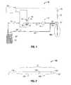
- FIG. 1shows an electrosurgical system 10 according to an embodiment of the present disclosure that includes an energy applicator or probe 100 .
- An embodiment of an energy applicator, such as the probe 100 of FIG. 1in accordance with the present disclosure, is shown in more detail in FIG. 2 . It will be understood, however, that other probe embodiments may also be used.
- Probe 100which is described in more detail later in this disclosure, generally includes an antenna assembly 12 having a radiating portion connected by a feedline 110 (or shaft) via a transmission line 15 to a connector 16 , which may further operably connect the probe 100 to a power generating source 28 , e.g., a microwave or radio frequency (RF) electrosurgical generator.
- Feedline 110may be coupled to a coolant port 51 to facilitate the flow of coolant or buffering fluid into, and out of, the probe 100 .
- Electrosurgical system 10in accordance with an embodiment of the present disclosure includes a power generating source 28 , a coolant supply system 11 adapted to provide coolant fluid “F” to the probe 100 , and a sensor unit 46 capable of detecting a gas bubble in the coolant supply system 11 .
- the sensor unit 46is electrically coupled to the power generating source 28 , and may be configured to generate an alarm signal to the power generating source 28 and, in response thereto, control logic, which may be associated with the power generating source 28 , may reduce the power output, e.g., for a predetermined time interval or until a manual reset switch is actuated.
- the coolant supply system 11includes a coolant source 18 , and may include a substantially closed loop having a first coolant path 19 leading to the probe 100 and a second coolant path 20 leading from the probe 100 .
- the size and shape of the first coolant path 19 and the second coolant path 20may be varied from the configuration depicted in FIG. 1 .
- Sensor unit 46may be configured to detect an air bubble in close proximity to the coolant source 18 .
- Coolant port 51may be in fluid communication with the coolant source 18 via the first coolant path 19 and/or the second coolant path 20 .
- the coolant supply system 11includes a first coolant path 19 and a second coolant path 20 , wherein the first coolant path 19 includes a coolant supply line 31 leading from the coolant source 18 to a coolant inlet port 52 that is defined in the coolant port 51 , and the second coolant path 20 includes a coolant return line 35 leading from a coolant outlet port 53 that is defined in the coolant port 51 to the coolant source 18 .
- Coolant source 18may be any suitable housing containing a reservoir of coolant fluid “F”.
- Coolant fluid “F”may be any suitable fluid that can be used for cooling or buffering the probe 100 , e.g., deionized water, or other suitable cooling medium.
- Coolant fluid “F”may have dielectric properties and may provide dielectric impedance buffering for the antenna assembly 12 .
- Coolant fluid “F”may be a conductive fluid, such as a saline solution, which may be delivered to the target tissue, e.g., to decrease impedance and allow increased power to be delivered to the target tissue.
- a coolant fluid “F” compositionmay vary depending upon desired cooling rates and the desired tissue impedance matching properties.
- liquidsincluding, but not limited to, water, saline, perfluorocarbon, such as the commercially available Fluorinert® perfluorocarbon liquid offered by Minnesota Mining and Manufacturing Company (3M), liquid chlorodifluoromethane, etc, in other variations, gases (such as nitrous oxide, nitrogen, carbon dioxide, etc.) may also be utilized as the cooling fluid.
- gasessuch as nitrous oxide, nitrogen, carbon dioxide, etc.
- a combination of liquids and/or gasesincluding, for example, those mentioned above, may be utilized as the coolant fluid “F”.
- a fluid movement device 34may be provided in the first coolant path 19 to move the coolant fluid “F” through the first coolant path 19 .
- Fluid movement device 34may include valves, pumps, power units, actuators, fittings, manifolds, etc. The position of the fluid movement device 34 may be varied from the configuration depicted in FIG. 1 . Fluid movement device 34 may additionally, or alternatively, be provided in the second coolant path 20 .
- the coolant supply system 11 shown in FIG. 1includes a single, fluid movement device 34 positioned in the first coolant path 19 , various combinations of different numbers of fluid movement devices, variedly sized and variedly spaced apart from each other, may be provided in the first coolant path 19 and/or the second coolant path 20 .
- Sensor unit 46may be disposed at any suitable position to allow for the detection of a gas bubble in the coolant supply system 11 .
- the sensor unit 46is disposed such that a gas bubble in the coolant supply system 11 can be detected before the bubble can be introduced into the probe 100 .
- Sensor unit 46may be disposed in the first coolant path 19 , and may be disposed in close proximity to the coolant source 18 .
- the sensor unit 46is electrically coupled to the power generating source 28 , and the detection of a bubble may trigger an alarm signal to the power generating source 28 . Electrical characteristics of the power generating source 28 may be controlled in response to the alarm signal.
- the electrosurgical system 10reduces the power and/or voltage output of the power generating source 28 , thereby reducing energy applicator power output to a low level, in response to the alarm signal.
- the sensor unit 46includes an optical detector, and may be used to monitor the coolant fluid “F” flow in the coolant supply line 31 to detect the presence of air or other gas within the coolant fluid “F” flow.
- Audible indicatory meansmay be incorporated or associated with the electrosurgical system 10 to notify the operator of the bubble condition.
- the operatormay take steps, e.g., perform visual inspection of the coolant fluid “F” in the coolant source 18 and/or visual inspection of the first coolant path 19 , or portions thereof, to verify that the coolant supply system 11 is functioning properly.
- a “reset” button(not shown) may be provided to allow the power generating source 28 to return to normal mode.
- sensor unit 46generally includes a light source or light-emitting element 43 (also referred to herein as optical transmitter 43 ) and a light receiving element 40 (also referred to herein as optical receiver 40 ).
- Optical transmitter 43may include any suitable device configured to transmit optical signals, e.g., a light-emitting diode (LED) 42 .
- Optical receiver 40may include any suitable device configured to receive optical signals, e.g., a photo-diode 41 .
- an LED 42 and a photo-diode 41are arranged on opposite sides of a coolant line, e.g., the coolant supply line 31 .
- LED 42may be configured to transmit either a continuous or pulsed optical signal through the coolant supply line 31 .
- Photo-diode 41may be positioned to receive the transmitted optical signal on the opposite side of the coolant supply line 31 from the LED 42 .
- a fixture housing an LED 42 and photo-diode 41 pairmay be provided to allow the sensor unit 46 (also referred to herein as optical detector 46 ) to be clipped or otherwise fastened to a portion of the coolant supply line 31 , e.g., to provide reliable orientation and shield the optical detector 46 from ambient light interference.
- an air or other gas bubblemay be detected by the optical detector 46 by either signal intensity or signal position at the optical receiver 40 .
- Air and liquidshave different degrees of attenuation per unit length and different refractive index values (e.g., water has a higher refractive index than air). Air has a refractive index of about 1.0003, and water has a refractive index of about 1.33.
- the optical detector 46detects the change in intensity of light collected at the photo-diode 41 , compared to the intensity of light collected at the photo-diode 41 when fluid “F” passes through the coolant supply line 31 .
- the change in intensity of light collected at the photo-diode 41is interpreted as indicator of the presence of an air bubble.
- an LED 42 and a photo-diode 41are configured to communicate when fluid “F” is present in the coolant supply line 31 .
- the varied refraction angledeflects light away from its intended photo-diode 41 and very little light impinges upon the photo-diode 41 .
- sensor unit 46uses signal position to detect an air bubble, the absence of light impinging upon the photo-diode 41 is interpreted as indicator of the presence of an air bubble.
- a logic circuit (not shown) in the sensor unit 46may relay information through digital or analog communication to the power generating source 28 indicating whether the optical detector 46 is in the no-bubble state or bubble state.
- the optical detector 46may be a separate device that plugs into digital or analog inputs on the power generating source 28 , programmed according to the communication protocol of the optical detector 46 .
- the power generating source 28is configured to provide microwave energy at an operational frequency from about 500 MHz to about 2500 MHz. In other embodiments, the power generating source 28 is configured to provide microwave energy at an operational frequency from about 500 MHz to about 10 GHz. Power generating source 28 may be configured to provide various frequencies of electromagnetic energy. Transmission line 15 may additionally, or alternatively, provide a conduit (not shown) configured to provide coolant fluid “F” from the coolant source 18 to the probe 100 .
- Feedline 110may electrically connect the antenna assembly 12 via the transmission line 15 to the power generating source 28 , and may include a coaxial cable, which may be semi-rigid or flexible. Feedline 110 may have a variable length from a proximal end of the antenna assembly 12 to a distal end of transmission line 15 ranging from a length of about one inch to about twelve inches. Feedline 110 may be constructed of a variety of electrically conductive materials, e.g., copper, gold, or other conductive metals with similar conductivity values. Feedline 110 may be made of stainless steel, which generally offers the strength required to puncture tissue and/or skin. Conductive materials used to form the feedline 110 may be plated with other materials, e.g., other conductive materials, to improve their properties, e.g., to improve conductivity or decrease energy loss, etc.
- a coaxial cablewhich may be semi-rigid or flexible.
- Feedline 110may have a variable length from a proximal end of the antenna assembly 12
- the feedline 110includes stainless steel, and to improve its conductivity, the stainless steel may be coated with a layer of a conductive material such as copper or gold.
- Feedline 110may include an inner conductor, a dielectric material coaxially surrounding the inner conductor, and an outer conductor coaxially surrounding the dielectric material.
- Antenna assembly 12may be formed from a portion of the inner conductor that extends distal of the feedline 110 into the antenna assembly 12 .
- the feedline 110may be formed from a coaxial, semi-rigid or flexible cable having a wire with a 0.047′′ outer diameter rated for 50 Ohms.
- Feedline 110may be cooled by fluid e.g., saline or water, to improve power handling, and may include a stainless steel catheter.
- an end cap or tapered portion 120Located at the distal end of the antenna assembly 12 is an end cap or tapered portion 120 , which may terminate in a sharp tip 123 to allow for insertion into tissue with minimal resistance.
- a straight probe with a sharp tipthat may be suitable for use as the energy applicator 100 is commercially available under the trademark EVIDENTTM offered by Covidien.
- the end cap or tapered portion 120may include other shapes, such as, for example, a tip 123 that is rounded, flat, square, hexagonal, or cylindroconical.
- the antenna assembly 12includes a distal radiating portion 105 and a proximal radiating portion 140 .
- a junction 130couples the proximal radiating portion 140 and the distal radiating portion 105 .
- the distal and proximal radiating portions 105 , 140align at the junction 130 , which is generally made of a dielectric material, e.g., adhesives, and are also supported by the inner conductor that extends at least partially through the distal radiating portion 105 .
- Junction 130or portions thereof, may be disposed between the proximal and distal radiating portions, 140 and 105 .
- Junction 130may be formed from any suitable elastomeric or ceramic dielectric material by any suitable process.
- the junction 130is formed by overmolding and includes a thermoplastic elastomer, such as, for example, polyether block amide (e.g., PEBAX®, manufactured by The Arkema Group of Colombes, France), polyetherimide (e.g., ULTEM® and/or EXTEM®, manufactured by SABIC Innovative Plastics of Saudi Arabia) and/or polyimide-based polymer (e.g., VESPEL®, manufactured by E. I. du Pont de Nemours and Company of Wilmington, Del., United States).
- Junction 130may be formed using any suitable overmolding compound by any suitable process, and may include use of a ceramic substrate.
- the antenna assembly 12may be provided with a coolant chamber (e.g., 337 shown in FIG. 3 ). Additionally, the junction 130 may include coolant inflow and outflow ports (not shown) to facilitate the flow of coolant into, and out of, the coolant chamber. Examples of coolant chamber and coolant inflow and outflow port embodiments are disclosed in commonly assigned U.S. patent application Ser. No. 12/401,268 filed on Mar. 10, 2009, entitled “COOLED DIELECTRICALLY BUFFERED MICROWAVE DIPOLE ANTENNA”, and U.S. Pat. No. 7,311,703 entitled “DEVICES AND METHODS FOR COOLING MICROWAVE ANTENNAS”.
- the antenna assembly 12may be provided with an outer jacket (e.g., 339 shown in FIG. 3 ) disposed about the distal radiating portion 105 , the junction 130 and/or the proximal radiating portion 140 .
- the outer jacketmay be formed of any suitable material, such as, for example, polymeric or ceramic materials.
- the outer jacketmay be applied by any suitable method, such as, for example, heat shrinking, overmolding, coating, spraying dipping, powder coating, baking and/or film deposition.
- the outer jacketmay be a water cooled catheter formed of a material having low electrical conductivity.
- the probe 100is inserted into or placed adjacent to tissue and microwave energy is supplied thereto.
- Ultrasound or computed tomography (CT) guidancemay be used to accurately guide the probe 100 into the area of tissue to be treated.
- Probe 100may be placed percutaneously or atop tissue, e.g., using conventional surgical techniques by surgical staff.
- a clinicianmay pre-determine the length of time that microwave energy is to be applied.
- Application durationmay depend on many factors such as tumor size and location and whether the tumor was a secondary or primary cancer.
- the duration of microwave energy application using the probe 100may depend on the progress of the heat distribution within the tissue area that is to be destroyed and/or the surrounding tissue.
- Single or multiple probes 100may provide ablations in short procedure times, e.g., a few minutes, to destroy cancerous cells in the target tissue region.
- a plurality of probes 100may be placed in variously arranged configurations to substantially simultaneously ablate a target tissue region, making faster procedures possible. Multiple probes 100 can be used to synergistically create a large ablation or to ablate separate sites simultaneously. Tissue ablation size and geometry is influenced by a variety of factors, such as the energy applicator design, number of energy applicators used simultaneously, time and wattage.
- microwave energy having a wavelength, lambda ( ⁇ )is transmitted through the antenna assembly 12 , e.g., along the proximal and distal radiating portions 140 , 105 , and radiated into the surrounding medium, e.g., tissue.
- the length of the antenna for efficient radiationmay be dependent on the effective wavelength, ⁇ eff , which is dependent upon the dielectric properties of the medium being radiated into.
- Antenna assembly 12 through which microwave energy is transmitted at a wavelength, ⁇may have differing effective wavelengths, ⁇ eff , depending upon the surrounding medium, e.g., liver tissue as opposed to breast tissue.
- FIG. 3shows an electrosurgical system 1000 according to an embodiment of the present disclosure that includes an antenna assembly 312 substantially disposed within a sheath 338 .
- Antenna assembly 312is similar to the antenna assembly 12 shown in FIG. 2 and further description thereof is omitted in the interests of brevity.
- a feedline 110couples the antenna assembly 312 to a connection hub 322 .
- Connection hub 322which is described in more detail later in this disclosure, generally includes a cable connector 379 and fluid ports 330 and 332 .
- Sheath 338generally includes a tubular member 339 defining a lumen into which the antenna assembly 312 , or portion thereof, may be positioned. In some embodiments, the sheath 338 is disposed over and encloses the feedline 110 , the proximal radiating portion 140 and the distal radiating portion 105 , and may at least partially enclose the tip 123 . In accordance with the embodiment shown in FIG. 3 , a coolant chamber 337 is defined between the tubular member 339 and the outer surfaces of the feedline 110 , the proximal radiating portion 140 and the distal radiating portion 105 .
- Coolant chamber 337is adapted to circulate coolant fluid “F” therethrough, and may include baffles, multiple lumens, flow restricting devices, or other structures that may redirect, concentrate, or disperse flow depending on their shape. Examples of coolant chamber embodiments are disclosed in commonly assigned U.S. patent application Ser. No. 12/350,292 filed on Jan. 8, 2009, entitled “CHOKED DIELECTRIC LOADED TIP DIPOLE MICROWAVE ANTENNA”. The size and shape of the sheath 338 and the coolant chamber 337 extending therethrough may be varied from the configuration depicted in FIG. 3 .
- Electrosurgical system 1000in accordance with an embodiment of the present disclosure includes a power generating source 328 , a coolant supply system 313 adapted to provide coolant fluid “F” via a connection hub 322 to the antenna assembly 312 , and a sensor unit 346 capable of detecting a gas bubble in the coolant supply system 313 and electrically coupled via transmission lines 301 and 302 to the power generating source 328 .
- Electrosurgical system 1000may further include a flow-diverter apparatus 350 operably associated with the sensor unit 346 and disposed in fluid communication between the sensor unit 346 and the connection hub 322 .
- the sensor unit 346when the sensor unit 346 detects an air or other gas bubble in the coolant supply system 313 , the sensor unit 346 transmits an electrical signal via transmission line 302 to the power generating source 28 and the flow-diverter apparatus 350 .
- Sensor unit 346 and the power generating source 328are similar to the sensor unit 46 and the power generating source 28 , respectively, shown in FIG. 1 and further description thereof is omitted in the interests of brevity.
- Coolant supply system 313generally includes a coolant source 336 , a first coolant path 319 leading from the coolant source 336 to the connection hub 322 , and a second coolant path 320 leading from the connection hub 322 to the coolant source 336 .
- the first coolant path 319includes a first fluid movement device 344 configured to move coolant fluid “F” through the first coolant path 319
- the second coolant path 320includes a second fluid movement device 334 configured to move coolant fluid “F” through the second coolant path 320 .
- Coolant source 336stores coolant fluid “F”, and may maintain coolant fluid “F” at a predetermined temperature.
- the coolant source 336may include a cooling unit (not shown) that cools the returning coolant fluid “F” from the antenna assembly 312 .
- Connection hub 322may have a variety of suitable shapes, e.g., cylindrical, rectangular, etc.
- the connection hub 322includes a cable connector 379 , an outlet fluid port 330 and an inlet fluid port 332 .
- Connection hub 322may include a three-branch luer type connector 372 having a middle branch 374 used to house the cable connector 379 and two outer branches 376 and 378 to house the outlet and inlet fluid ports 330 and 332 , respectively.
- Connection hub 322may be formed of any of a variety of materials, e.g., any suitable non-conductive conformal material.
- non-conductive conformal materialsthat may be suitable for forming the connection hub 322 include polyesters, polyimides, polyamides, polyamide-imides, polyetherimides, polyacrylates, polyethylene terephthalate, polyethylene, polypropylene, polyvinylidene chloride, polysiloxanes, combinations thereof and the like.
- Connection hub 322may be adapted to be connected in fluid communication with the sheath 338 .
- the sheath 338is coupled to the connection hub 322 and the tip 123 , thereby defining a chamber 337 around the feedline 110 , the proximal radiating portion 140 and the distal radiating portion 105 .
- the first coolant path 319includes a coolant supply line 386 leading from the coolant source 336 to the inlet fluid port 332 .
- First fluid movement device 344may be disposed in fluid communication between the inlet fluid port 332 and the coolant source 336 .
- the second coolant path 320includes a coolant return line 388 leading from the outlet fluid port 330 to the coolant source 336 .
- Second fluid movement device 334may be disposed in fluid communication between the outlet fluid port 330 and the coolant source 336 .
- the positions of the first fluid movement device 344 and the second fluid movement device 334e.g., in relation to the coolant source 336 , may be varied from the configuration depicted in FIG. 3 .
- a controller 351 associated with the flow-diverter apparatus 350may actuate a fluid flow diverter 352 to divert coolant fluid “F” flow to a third coolant fluid path 321 .
- Fluid flow diverter 352may be any suitable device for selectively diverting the coolant fluid “F” flow.
- Third coolant fluid path 321may lead from the flow-diverter apparatus 350 to a container 390 .
- Controller 351may include any type of computing device, computational circuit, or any type of processor or processing circuit capable of executing a series of instructions that are stored in a memory (not shown) of the controller 351 .
- the flow-diverter apparatus 350includes a valve (not shown) that includes a valve body and an electromechanical actuator operatively coupled to the valve body. Controller 351 may control fluid flow diverter 352 by activating the actuator, e.g., according to a predetermined valve control sequence.
- a valve control sequencemay involve moving the valve from a first position, in which coolant fluid “F” flows towards the connection hub 322 , to a second position, in which the coolant fluid “F” having an air or other gas bubble entrained therein flows into the container 390 , and returning to the first position, e.g., after a predetermined time interval, thereby re-establishing coolant fluid “F” flow towards the connection hub 322 .
- FIG. 4is a flowchart illustrating a method of detecting a bubble in a fluid flow according to an embodiment of the present disclosure.
- an optical sensor unite.g., 46 shown in FIG. 1
- the optical sensor unitis operably associated with a fluid path (e.g., 19 shown in FIG. 1 ).
- the light emitting element and light-receiving elementare disposed such that light directed from the light-emitting element passes through the fluid path to the light-receiving element during the fluid flow in the fluid path.
- step 420a first reference value is determined based on an air flow in the fluid path passing through the optical sensor, and a second reference value is determined based on a fluid flow in the fluid path passing through the optical sensor unit.
- step 420may further include steps 421 and 422 .
- step 421light from the light-emitting element is directed through the air flow in the fluid path passing through the optical sensor unit and a characteristic of light collected at the light-receiving element is sensed to determine the first reference value.
- step 422light from the light-emitting element is directed through the fluid flow in the fluid path passing through the optical sensor unit and a characteristic of light collected at the light-receiving element is sensed to determine the second reference value.
- the sensed characteristic of lightis an intensity of light collected at the light-receiving element. In other embodiments, the sensed characteristic of light is an absence of light incident on the light-receiving element.
- the optical sensor unitis used to monitor the fluid flow in the fluid path to detect an air bubble in the fluid flow using at least one of the first reference value or the second reference value.
- the change in intensity of light collected at the light-receiving elementis interpreted as indicator of the presence of an air bubble.
- step 440when an air bubble in the fluid flow is detected by the optical sensor unit, an electrical signal is transmitted from the optical sensor unit.
- the sensor unitdetects an air (or other gas) bubble in the coolant supply system, the sensor unit transmits an electrical signal to a power generating source (e.g., 28 shown in FIG. 1 ).
- FIG. 6is a flowchart illustrating a method of detecting a bubble in a fluid flow according to an embodiment of the present disclosure.
- a fluid sourcee.g., 336 shown in FIG. 3
- the fluid sourcemay include any suitable source, e.g., a container of coolant or dielectric-buffering fluid.
- an optical sensor unit(e.g., 346 shown in FIG. 3 ) is provided that includes a light-emitting element (e.g., 43 shown in FIG. 3 ) and a light-receiving element (e.g., 40 shown in FIG. 3 )
- the optical sensor unitis operably associated with a fluid path (e.g., 319 shown in FIG. 3 ), the fluid path leading from the fluid source to an electrosurgical device (e.g., 312 shown in FIG. 3 ) operably associated with an electrosurgical generator (e.g., 328 shown in FIG. 3 ).
- a first calibration stepis performed by directing light from the light-emitting element through an air flow in the fluid path passing through the optical sensor unit and a characteristic of light collected at the light-receiving element is sensed to determine a first reference value.
- a second calibration stepis performed by directing light from the light-emitting element through a fluid flow in the fluid path passing through the optical sensor unit and a characteristic of light collected at the light-receiving element is sensed to determine a second reference value.
- step 650the optical sensor unit is operated to direct light from the light-emitting element through the fluid flow in the fluid path passing through the optical sensor unit and a characteristic of light collected at the light-receiving element is sensed to determine a third reference value.
- an electrosurgical generatorwhich may be used to activate the electrosurgical device, is controlled based on a comparison result of a comparison of the third reference value to the first reference value and the second reference value.
- the optical sensor unitis electrically coupled to the electrosurgical generator. Based on the comparison result, the optical sensor unit may output an electrical signal to the electrosurgical generator and, in response thereto, the power output of the electrosurgical generator may be reduced, e.g., for a predetermined time interval or until a manual reset switch is actuated. In some embodiments, the optical sensor unit outputs an electrical signal when the third reference value is determined to be substantially equal to the first reference value.
- the fluid flowmay be diverted by a flow-diverter apparatus (e.g., 350 shown in FIG. 3 ) to a different fluid path (e.g., 321 shown in FIG. 3 ) for a predetermined period of time based on the comparison result.
- the predetermined period of timemay be a period of time to allow for the air bubble to pass out of the fluid path (e.g., 319 shown in FIG. 3 ) that leads to the electrosurgical device and, instead, into a different fluid path (e.g., 321 shown in FIG. 3 ), e.g., leading to a container (e.g., 390 shown in FIG. 3 ).
- the electrosurgical systeme.g., 1000 shown in FIG. 3
Landscapes
- Health & Medical Sciences (AREA)
- Surgery (AREA)
- Life Sciences & Earth Sciences (AREA)
- Engineering & Computer Science (AREA)
- Biomedical Technology (AREA)
- Molecular Biology (AREA)
- Nuclear Medicine, Radiotherapy & Molecular Imaging (AREA)
- Veterinary Medicine (AREA)
- Physics & Mathematics (AREA)
- Heart & Thoracic Surgery (AREA)
- Medical Informatics (AREA)
- Otolaryngology (AREA)
- Animal Behavior & Ethology (AREA)
- General Health & Medical Sciences (AREA)
- Public Health (AREA)
- Plasma & Fusion (AREA)
- Electromagnetism (AREA)
- Surgical Instruments (AREA)
Abstract
Description
Claims (10)
Priority Applications (2)
| Application Number | Priority Date | Filing Date | Title |
|---|---|---|---|
| US12/566,299US8394087B2 (en) | 2009-09-24 | 2009-09-24 | Optical detection of interrupted fluid flow to ablation probe |
| US13/791,262US8894640B2 (en) | 2009-09-24 | 2013-03-08 | Optical detection of interrupted fluid flow to ablation probe |
Applications Claiming Priority (1)
| Application Number | Priority Date | Filing Date | Title |
|---|---|---|---|
| US12/566,299US8394087B2 (en) | 2009-09-24 | 2009-09-24 | Optical detection of interrupted fluid flow to ablation probe |
Related Child Applications (1)
| Application Number | Title | Priority Date | Filing Date |
|---|---|---|---|
| US13/791,262DivisionUS8894640B2 (en) | 2009-09-24 | 2013-03-08 | Optical detection of interrupted fluid flow to ablation probe |
Publications (2)
| Publication Number | Publication Date |
|---|---|
| US20110071582A1 US20110071582A1 (en) | 2011-03-24 |
| US8394087B2true US8394087B2 (en) | 2013-03-12 |
Family
ID=43757289
Family Applications (2)
| Application Number | Title | Priority Date | Filing Date |
|---|---|---|---|
| US12/566,299Expired - Fee RelatedUS8394087B2 (en) | 2009-09-24 | 2009-09-24 | Optical detection of interrupted fluid flow to ablation probe |
| US13/791,262Expired - Fee RelatedUS8894640B2 (en) | 2009-09-24 | 2013-03-08 | Optical detection of interrupted fluid flow to ablation probe |
Family Applications After (1)
| Application Number | Title | Priority Date | Filing Date |
|---|---|---|---|
| US13/791,262Expired - Fee RelatedUS8894640B2 (en) | 2009-09-24 | 2013-03-08 | Optical detection of interrupted fluid flow to ablation probe |
Country Status (1)
| Country | Link |
|---|---|
| US (2) | US8394087B2 (en) |
Cited By (22)
| Publication number | Priority date | Publication date | Assignee | Title |
|---|---|---|---|---|
| US20110021888A1 (en)* | 2009-06-26 | 2011-01-27 | Cianna Medical, Inc. | Apparatus, systems, and methods for localizing markers or tissue structures within a body |
| US20110316539A1 (en)* | 2009-03-20 | 2011-12-29 | Koninklijke Philips Electronics N.V. | Antenna array comprising at least one dipole antenna for magnetic resonance imaging |
| US8652127B2 (en) | 2010-05-26 | 2014-02-18 | Covidien Lp | System and method for chemically cooling an ablation antenna |
| US8894640B2 (en) | 2009-09-24 | 2014-11-25 | Covidien Lp | Optical detection of interrupted fluid flow to ablation probe |
| US9028476B2 (en) | 2011-02-03 | 2015-05-12 | Covidien Lp | Dual antenna microwave resection and ablation device, system and method of use |
| US9192440B2 (en) | 2010-02-05 | 2015-11-24 | Covidien Lp | Electrosurgical devices with choke shorted to biological tissue |
| US9192437B2 (en) | 2009-05-27 | 2015-11-24 | Covidien Lp | Narrow gauge high strength choked wet tip microwave ablation antenna |
| US9241762B2 (en) | 2010-06-03 | 2016-01-26 | Covidien Lp | Specific absorption rate measurement and energy-delivery device characterization using image analysis |
| US9254172B2 (en) | 2008-09-03 | 2016-02-09 | Covidien Lp | Shielding for an isolation apparatus used in a microwave generator |
| US9271788B2 (en) | 2010-03-26 | 2016-03-01 | Cividien LP | Ablation devices with adjustable radiating section lengths, electrosurgical systems including same, and methods of adjusting ablation fields using same |
| US9375278B2 (en) | 2009-09-18 | 2016-06-28 | Covidien Lp | Tissue ablation system with energy distribution |
| US9480527B2 (en) | 2010-03-08 | 2016-11-01 | Covidien Lp | Microwave antenna probe having a deployable ground plane |
| US10028787B2 (en) | 2010-02-26 | 2018-07-24 | Covidien Lp | Tunable microwave ablation probe |
| US10213256B2 (en) | 2009-10-28 | 2019-02-26 | Covidien Lp | System and method for monitoring ablation size |
| US10251701B2 (en) | 2010-05-25 | 2019-04-09 | Covidien Lp | Flow rate verification monitor for fluid-cooled microwave ablation probe |
| US10327845B2 (en) | 2010-01-25 | 2019-06-25 | Covidien Lp | System and method for monitoring ablation size |
| US10390882B2 (en) | 2009-09-29 | 2019-08-27 | Covidien Lp | Flow rate monitor for fluid cooled microwave ablation probe |
| US20190390885A1 (en)* | 2018-06-22 | 2019-12-26 | Emerson Climate Technologies Retail Solutions, Inc. | Systems And Methods For Optical Detection Of Refrigeration System Abnormalities |
| US10588684B2 (en) | 2010-07-19 | 2020-03-17 | Covidien Lp | Hydraulic conductivity monitoring to initiate tissue division |
| US10987152B2 (en) | 2010-02-19 | 2021-04-27 | Covidien Lp | Ablation devices with dual operating frequencies, systems including same, and methods of adjusting ablation volume using same |
| US11179220B2 (en) | 2009-06-26 | 2021-11-23 | Cianna Medical, Inc. | Apparatus, systems, and methods for localizing markers or tissue structures within a body |
| US11432870B2 (en) | 2016-10-04 | 2022-09-06 | Avent, Inc. | Cooled RF probes |
Families Citing this family (16)
| Publication number | Priority date | Publication date | Assignee | Title |
|---|---|---|---|---|
| US7553309B2 (en) | 2004-10-08 | 2009-06-30 | Covidien Ag | Electrosurgical system employing multiple electrodes and method thereof |
| US8323275B2 (en) | 2009-06-19 | 2012-12-04 | Vivant Medical, Inc. | Laparoscopic port with microwave rectifier |
| US8069553B2 (en) | 2009-09-09 | 2011-12-06 | Vivant Medical, Inc. | Method for constructing a dipole antenna |
| US9113925B2 (en)* | 2009-09-09 | 2015-08-25 | Covidien Lp | System and method for performing an ablation procedure |
| US8568401B2 (en) | 2009-10-27 | 2013-10-29 | Covidien Lp | System for monitoring ablation size |
| US8382750B2 (en)* | 2009-10-28 | 2013-02-26 | Vivant Medical, Inc. | System and method for monitoring ablation size |
| US8394092B2 (en)* | 2009-11-17 | 2013-03-12 | Vivant Medical, Inc. | Electromagnetic energy delivery devices including an energy applicator array and electrosurgical systems including same |
| US10039601B2 (en) | 2010-03-26 | 2018-08-07 | Covidien Lp | Ablation devices with adjustable radiating section lengths, electrosurgical systems including same, and methods of adjusting ablation fields using same |
| US8672933B2 (en) | 2010-06-30 | 2014-03-18 | Covidien Lp | Microwave antenna having a reactively-loaded loop configuration |
| US9579150B2 (en) | 2011-04-08 | 2017-02-28 | Covidien Lp | Microwave ablation instrument with interchangeable antenna probe |
| US8888771B2 (en) | 2011-07-15 | 2014-11-18 | Covidien Lp | Clip-over disposable assembly for use with hemostat-style surgical instrument and methods of manufacturing same |
| DE102012204680B4 (en) | 2012-03-23 | 2019-04-25 | Olympus Winter & Ibe Gmbh | Method and system for flushing solution supply during endoscopic procedures |
| US9301723B2 (en) | 2013-03-15 | 2016-04-05 | Covidien Lp | Microwave energy-delivery device and system |
| US9119650B2 (en) | 2013-03-15 | 2015-09-01 | Covidien Lp | Microwave energy-delivery device and system |
| WO2017214193A1 (en)* | 2016-06-06 | 2017-12-14 | Buffalo Filter Llc | Sensor systems for use in connection with medical procedures |
| US10543036B2 (en)* | 2017-06-13 | 2020-01-28 | Covidien Lp | Systems and methods of cooling surgical instruments |
Citations (149)
| Publication number | Priority date | Publication date | Assignee | Title |
|---|---|---|---|---|
| SU166452A1 (en) | В. А. Костров , Л. В. Смирнов | STOMATOLOGICAL DIATHERMOKOAGULATOR | ||
| DE390937C (en) | 1922-10-13 | 1924-03-03 | Adolf Erb | Device for internal heating of furnace furnaces for hardening, tempering, annealing, quenching and melting |
| DE1099658B (en) | 1959-04-29 | 1961-02-16 | Siemens Reiniger Werke Ag | Automatic switch-on device for high-frequency surgical devices |
| FR1275415A (en) | 1960-09-26 | 1961-11-10 | Device for detecting disturbances for electrical installations, in particular electrosurgery | |
| DE1139927B (en) | 1961-01-03 | 1962-11-22 | Friedrich Laber | High-frequency surgical device |
| DE1149832B (en) | 1961-02-25 | 1963-06-06 | Siemens Reiniger Werke Ag | High frequency surgical apparatus |
| FR1347865A (en) | 1962-11-22 | 1964-01-04 | Improvements to diathermo-coagulation devices | |
| DE1439302A1 (en) | 1963-10-26 | 1969-01-23 | Siemens Ag | High-frequency surgical device |
| SU401367A1 (en) | 1971-10-05 | 1973-10-12 | Тернопольский государственный медицинский институт | BIAKTIVNYE ELECTRO SURGICAL INSTRUMENT |
| FR2235669A1 (en) | 1973-07-07 | 1975-01-31 | Lunacek Boris | Gynaecological sterilisation instrument - has hollow electrode protruding from the end of a curved ended tube |
| DE2439587A1 (en) | 1973-08-23 | 1975-02-27 | Matburn Holdings Ltd | ELECTROSURGICAL DEVICE |
| DE2455174A1 (en) | 1973-11-21 | 1975-05-22 | Termiflex Corp | INPUT / OUTPUT DEVICE FOR DATA EXCHANGE WITH DATA PROCESSING DEVICES |
| DE2407559A1 (en) | 1974-02-16 | 1975-08-28 | Dornier System Gmbh | Tissue heat treatment probe - has water cooling system which ensures heat development only in treated tissues |
| DE2415263A1 (en) | 1974-03-29 | 1975-10-02 | Aesculap Werke Ag | Surgical H.F. coagulation probe has electrode tongs - with exposed ends of insulated conductors forming tong-jaws |
| DE2429021A1 (en) | 1974-06-18 | 1976-01-08 | Erbe Elektromedizin | Remote control for HF surgical instruments - uses cable with two conductors at most |
| FR2276027A1 (en) | 1974-06-25 | 1976-01-23 | Medical Plastics Inc | Plate electrode with connector - is clamped between connector jaws held by releasable locking device |
| DE2460481A1 (en) | 1974-12-20 | 1976-06-24 | Delma Elektro Med App | Electrode grip for remote HF surgical instrument switching - has shaped insulated piece with contact ring of sterilizable (silicon) rubber |
| DE2602517A1 (en) | 1975-01-23 | 1976-07-29 | Dentsply Int Inc | ELECTROSURGICAL DEVICE |
| DE2504280A1 (en) | 1975-02-01 | 1976-08-05 | Hans Heinrich Prof Dr Meinke | DEVICE FOR ELECTRIC TISSUE CUTTING IN SURGERY |
| FR2313708A1 (en) | 1975-06-02 | 1976-12-31 | Sybron Corp | Electro surgical instrument impulse control circuit - has potentiometer between patient electrodes and threshold switch for excessive voltage |
| DE2627679A1 (en) | 1975-06-26 | 1977-01-13 | Marcel Lamidey | HEMATISTIC HIGH FREQUENCY EXTRACTOR FORCEPS |
| DE2540968A1 (en) | 1975-09-13 | 1977-03-17 | Erbe Elektromedizin | Circuit for bipolar coagulation tweezers - permits preparation of tissues prior to coagulation |
| DE2820908A1 (en) | 1977-05-16 | 1978-11-23 | Joseph Skovajsa | DEVICE FOR THE LOCAL TREATMENT OF A PATIENT IN PARTICULAR FOR ACUPUNCTURE OR AURICULAR THERAPY |
| DE2803275A1 (en) | 1978-01-26 | 1979-08-02 | Aesculap Werke Ag | HF surgical appts. with active treatment and patient electrodes - has sensor switching generator to small voltage when hand-operated switch is closed |
| DE2823291A1 (en) | 1978-05-27 | 1979-11-29 | Rainer Ing Grad Koch | Coagulation instrument automatic HF switching circuit - has first lead to potentiometer and second to transistor base |
| SU727201A2 (en) | 1977-11-02 | 1980-04-15 | Киевский Научно-Исследовательский Институт Нейрохирургии | Electric surgical apparatus |
| DE2946728A1 (en) | 1979-11-20 | 1981-05-27 | Erbe Elektromedizin GmbH & Co KG, 7400 Tübingen | HF surgical appts. for use with endoscope - provides cutting or coagulation current at preset intervals and of selected duration |
| DE3143421A1 (en) | 1980-11-04 | 1982-05-27 | The Agency of Industrial Science and Technology, Tokyo | Laser scalpel |
| DE3045996A1 (en) | 1980-12-05 | 1982-07-08 | Medic Eschmann Handelsgesellschaft für medizinische Instrumente mbH, 2000 Hamburg | Electro-surgical scalpel instrument - has power supply remotely controlled by surgeon |
| FR2502935A1 (en) | 1981-03-31 | 1982-10-08 | Dolley Roger | Diathermic knife for coagulating tissues - has monitoring current added to HF coagulating current in order to control end of operation as function or resistance of coagulating tissues |
| DE3120102A1 (en) | 1981-05-20 | 1982-12-09 | F.L. Fischer GmbH & Co, 7800 Freiburg | ARRANGEMENT FOR HIGH-FREQUENCY COAGULATION OF EGG WHITE FOR SURGICAL PURPOSES |
| FR2517953A1 (en) | 1981-12-10 | 1983-06-17 | Alvar Electronic | Diaphanometer for optical examination of breast tissue structure - measures tissue transparency using two plates and optical fibre bundle cooperating with photoelectric cells |
| FR2573301A1 (en) | 1984-11-16 | 1986-05-23 | Lamidey Gilles | Surgical forceps and its control and monitoring apparatus |
| DE3510586A1 (en) | 1985-03-23 | 1986-10-02 | Erbe Elektromedizin GmbH, 7400 Tübingen | Control device for a high-frequency surgical instrument |
| DE3604823A1 (en) | 1986-02-15 | 1987-08-27 | Flachenecker Gerhard | HIGH FREQUENCY GENERATOR WITH AUTOMATIC PERFORMANCE CONTROL FOR HIGH FREQUENCY SURGERY |
| EP0246350A1 (en) | 1986-05-23 | 1987-11-25 | Erbe Elektromedizin GmbH. | Coagulation electrode |
| DE8712328U1 (en) | 1987-09-11 | 1988-02-18 | Jakoubek, Franz, 7201 Emmingen-Liptingen | Endoscopy forceps |
| DE3711511C1 (en) | 1987-04-04 | 1988-06-30 | Hartmann & Braun Ag | Method for determining gas concentrations in a gas mixture and sensor for measuring thermal conductivity |
| US4891483A (en)* | 1985-06-29 | 1990-01-02 | Tokyo Keiki Co. Ltd. | Heating apparatus for hyperthermia |
| DE3904558A1 (en) | 1989-02-15 | 1990-08-23 | Flachenecker Gerhard | Radio-frequency generator with automatic power control for radio-frequency surgery |
| US5006110A (en)* | 1987-12-01 | 1991-04-09 | Pacesetter Infusion, Ltd. | Air-in-line detector infusion system |
| DE3942998A1 (en) | 1989-12-27 | 1991-07-04 | Delma Elektro Med App | Electro-surgical HF instrument for contact coagulation - has monitoring circuit evaluating HF voltage at electrodes and delivering switch=off signal |
| US5072595A (en)* | 1990-09-19 | 1991-12-17 | Barbier William J | Apparatus for detecting small bubbles in a pressurized fluid stream |
| EP0481685A1 (en) | 1990-10-15 | 1992-04-22 | Cook Incorporated | Medical device for localizing a lesion |
| US5129396A (en) | 1988-11-10 | 1992-07-14 | Arye Rosen | Microwave aided balloon angioplasty with lumen measurement |
| EP0521264A2 (en) | 1991-07-03 | 1993-01-07 | W.L. Gore & Associates GmbH | Antenna device with feed |
| JPH055106A (en) | 1990-07-31 | 1993-01-14 | Matsushita Electric Works Ltd | Production of alloy sintered body |
| JPH0540112A (en) | 1991-02-08 | 1993-02-19 | Tokico Ltd | Sample liquid component analyzer |
| DE4238263A1 (en) | 1991-11-15 | 1993-05-19 | Minnesota Mining & Mfg | Adhesive comprising hydrogel and crosslinked polyvinyl:lactam - is used in electrodes for biomedical application providing low impedance and good mechanical properties when water and/or moisture is absorbed from skin |
| EP0541930A1 (en) | 1991-10-17 | 1993-05-19 | Acufex Microsurgical Inc. | Transmission link for use in surgical instruments |
| EP0556705A1 (en) | 1992-02-20 | 1993-08-25 | DELMA ELEKTRO-UND MEDIZINISCHE APPARATEBAU GESELLSCHAFT mbH | High frequency surgery device |
| EP0558429A1 (en) | 1992-02-26 | 1993-09-01 | PECHINEY RECHERCHE (Groupement d'Intérêt Economique géré par l'ordonnance no. 67-821 du 23 Septembre 1967) | Method of simultaneous measuring of electrical resistivety and thermal conductivity |
| EP0572131A1 (en) | 1992-05-21 | 1993-12-01 | Everest Medical Corporation | Surgical scissors with bipolar coagulation feature |
| DE4303882A1 (en) | 1993-02-10 | 1994-08-18 | Kernforschungsz Karlsruhe | Combined instrument for separating and coagulating in minimally invasive surgery |
| JPH06343644A (en) | 1993-05-04 | 1994-12-20 | Gyrus Medical Ltd | Surgical peritoneoscope equipment |
| DE4339049A1 (en) | 1993-11-16 | 1995-05-18 | Erbe Elektromedizin | Surgical system and instruments configuration device |
| JPH07265328A (en) | 1993-11-01 | 1995-10-17 | Gyrus Medical Ltd | Electrode assembly for electric surgery device and electric surgery device using it |
| JPH0856955A (en) | 1994-06-29 | 1996-03-05 | Gyrus Medical Ltd | Electric surgical apparatus |
| JPH08252263A (en) | 1994-12-21 | 1996-10-01 | Gyrus Medical Ltd | Electronic surgical incision instrument and electronic surgical incision device using the same |
| DE29616210U1 (en) | 1996-09-18 | 1996-11-14 | Olympus Winter & Ibe Gmbh, 22045 Hamburg | Handle for surgical instruments |
| JPH0910223A (en) | 1995-06-23 | 1997-01-14 | Gyrus Medical Ltd | Generator and system for electric operation |
| DE19608716C1 (en) | 1996-03-06 | 1997-04-17 | Aesculap Ag | Bipolar surgical holding instrument |
| US5697927A (en)* | 1992-12-01 | 1997-12-16 | Cardiac Pathways Corporation | Catheter for RF ablation with cooled electrode and apparatus for use therewith |
| EP0836868A2 (en) | 1996-10-18 | 1998-04-22 | Gebr. Berchtold GmbH & Co. | High frequency surgical apparatus and method for operating same |
| DE19751106A1 (en) | 1996-11-27 | 1998-05-28 | Eastman Kodak Co | Laser printer with array of laser diodes |
| DE19717411A1 (en) | 1997-04-25 | 1998-11-05 | Aesculap Ag & Co Kg | Monitoring of thermal loading of patient tissue in contact region of neutral electrode of HF treatment unit |
| DE19751108A1 (en) | 1997-11-18 | 1999-05-20 | Beger Frank Michael Dipl Desig | Electrosurgical operation tool, especially for diathermy |
| DE19801173C1 (en) | 1998-01-15 | 1999-07-15 | Kendall Med Erzeugnisse Gmbh | Clamp connector for film electrodes |
| JPH11244298A (en) | 1997-12-19 | 1999-09-14 | Gyrus Medical Ltd | Electric surgical instrument |
| US6007571A (en) | 1996-04-25 | 1999-12-28 | Urologix, Inc. | Liquid coolant supply system |
| DE19848540A1 (en) | 1998-10-21 | 2000-05-25 | Reinhard Kalfhaus | Circuit layout and method for operating a single- or multiphase current inverter connects an AC voltage output to a primary winding and current and a working resistance to a transformer's secondary winding and current. |
| JP2000342599A (en) | 1999-05-21 | 2000-12-12 | Gyrus Medical Ltd | Generator for electrosurgical operation, electrosurgical operation system, method for operating this system and method for performing amputation and resection of tissue by electrosurgical operation |
| JP2000350732A (en) | 1999-05-21 | 2000-12-19 | Gyrus Medical Ltd | Electrosurgical system, generator for electrosurgery, and method for cutting or excising tissue by electrosurgery |
| JP2001008944A (en) | 1999-05-28 | 2001-01-16 | Gyrus Medical Ltd | Electric surgical signal generator and electric surgical system |
| JP2001029356A (en) | 1999-06-11 | 2001-02-06 | Gyrus Medical Ltd | Electric and surgical signal generator |
| US6223085B1 (en) | 1997-05-06 | 2001-04-24 | Urologix, Inc. | Device and method for preventing restenosis |
| US6226080B1 (en) | 1998-03-24 | 2001-05-01 | Ngk Insulators, Ltd. | Method for detecting defect of transparent body, method for producing transparent body |
| JP2001128990A (en) | 1999-05-28 | 2001-05-15 | Gyrus Medical Ltd | Electro surgical instrument and electrosurgical tool converter |
| EP1159926A2 (en) | 2000-06-03 | 2001-12-05 | Aesculap Ag | Scissor- or forceps-like surgical instrument |
| US6355024B1 (en) | 1999-07-14 | 2002-03-12 | Mallinckrodt Inc. | Medical fluid delivery system |
| US6451015B1 (en)* | 1998-11-18 | 2002-09-17 | Sherwood Services Ag | Method and system for menu-driven two-dimensional display lesion generator |
| US20020151884A1 (en)* | 1998-07-07 | 2002-10-17 | Hoey Michael F. | Apparatus and method for creating, maintaining, and controlling a virtual electrode used for the ablation of tissue |
| US6575969B1 (en) | 1995-05-04 | 2003-06-10 | Sherwood Services Ag | Cool-tip radiofrequency thermosurgery electrode system for tumor ablation |
| DE10224154A1 (en) | 2002-05-27 | 2003-12-18 | Celon Ag Medical Instruments | Application device for electrosurgical device for body tissue removal via of HF current has electrode subset selected from active electrode set in dependence on measured impedance of body tissue |
| GB2403148A (en) | 2003-06-23 | 2004-12-29 | Microsulis Ltd | Radiation Applicator |
| US20050015081A1 (en) | 2003-07-18 | 2005-01-20 | Roman Turovskiy | Devices and methods for cooling microwave antennas |
| EP1506757A1 (en) | 2003-08-15 | 2005-02-16 | Alcon, Inc | Tip Assembly |
| DE10328514B3 (en) | 2003-06-20 | 2005-03-03 | Aesculap Ag & Co. Kg | Endoscopic surgical scissor instrument has internal pushrod terminating at distal end in transverse cylindrical head |
| US20050065584A1 (en) | 2003-09-09 | 2005-03-24 | Schiff Jonathan D. | System and method for cooling internal tissue |
| FR2862813A1 (en) | 2003-11-20 | 2005-05-27 | Pellenc Sa | METHOD FOR BALANCED LOADING OF LITHIUM-ION OR POLYMER LITHIUM BATTERY |
| FR2864439A1 (en) | 2003-12-30 | 2005-07-01 | Image Guided Therapy | Tumor treating device for use by surgeon, has generator applying voltage to each of active electrodes in manner independent from other electrodes and having sinusoidal voltage generation unit adjusting amplitude and phase of voltage |
| US20050245920A1 (en) | 2004-04-30 | 2005-11-03 | Vitullo Jeffrey M | Cell necrosis apparatus with cooled microwave antenna |
| DE102004022206A1 (en) | 2004-05-04 | 2005-12-01 | Bundesrepublik Deutschland, vertr. d. d. Bundesministerium für Wirtschaft und Arbeit, dieses vertr. d. d. Präsidenten der Physikalisch-Technischen Bundesanstalt | Sensor for measuring thermal conductivity comprises a strip composed of two parallel sections, and two outer heating strips |
| DE202005015147U1 (en) | 2005-09-26 | 2006-02-09 | Health & Life Co., Ltd., Chung-Ho | Biosensor test strip with identifying function for biological measuring instruments has functioning electrode and counter electrode, identification zones with coating of electrically conductive material and reaction zone |
| US7161313B2 (en) | 1997-08-26 | 2007-01-09 | Color Kinetics Incorporated | Light emitting diode based products |
| WO2007006158A1 (en) | 2005-07-14 | 2007-01-18 | Baylis Medical Company Inc. | Electrosurgical device and methods |
| US20070142829A1 (en) | 2005-12-20 | 2007-06-21 | Pohang University Of Science And Technology | In-vivo interstitial antennas |
| EP1905375A1 (en) | 2006-09-29 | 2008-04-02 | Vivant Medical, Inc. | Microwave antenna assembly |
| US20080161890A1 (en) | 2007-01-03 | 2008-07-03 | Boston Scientific Scimed, Inc. | Methods, systems, and apparatuses for protecting esophageal tissue during ablation |
| US20080183165A1 (en)* | 2007-01-31 | 2008-07-31 | Steven Paul Buysse | Thermal Feedback Systems and Methods of Using the Same |
| US20080269851A1 (en)* | 2007-04-19 | 2008-10-30 | Deem Mark E | Systems and methods for creating an effect using microwave energy to specified tissue |
| US20090138005A1 (en)* | 2007-11-27 | 2009-05-28 | Vivant Medical, Inc. | Targeted Cooling of Deployable Microwave Antenna |
| US20090183895A1 (en)* | 2008-01-23 | 2009-07-23 | Vivant Medical, Inc. | Thermally Tuned Coaxial Cable for Microwave Antennas |
| US20090187180A1 (en)* | 2008-01-23 | 2009-07-23 | Vivant Medical, Inc. | Choked Dielectric Loaded Tip Dipole Microwave Antenna |
| US20090192510A1 (en)* | 2008-01-29 | 2009-07-30 | Tyco Healthcare Group Lp | Polyp Encapsulation System and Method |
| US20090198226A1 (en)* | 2008-01-31 | 2009-08-06 | Vivant Medical, Inc. | Medical Device Including Member that Deploys in a Spiral-Like Configuration and Method |
| US20090198227A1 (en)* | 2008-01-31 | 2009-08-06 | Vivant Medical, Inc. | Articulating Ablation Device and Method |
| US20090222002A1 (en)* | 2008-03-03 | 2009-09-03 | Vivant Medical, Inc. | Intracooled Percutaneous Microwave Ablation Probe |
| US20090248006A1 (en)* | 2008-03-31 | 2009-10-01 | Paulus Joseph A | Re-Hydration Antenna for Ablation |
| US20090248005A1 (en)* | 2008-03-27 | 2009-10-01 | Rusin Christopher T | Microwave Ablation Devices Including Expandable Antennas and Methods of Use |
| US20090264877A1 (en)* | 2008-04-17 | 2009-10-22 | Vivant Medical, Inc. | High-Strength Microwave Antenna Coupling |
| US20090295674A1 (en)* | 2008-05-29 | 2009-12-03 | Kenlyn Bonn | Slidable Choke Microwave Antenna |
| US20090306659A1 (en)* | 2008-06-09 | 2009-12-10 | Buysse Steven P | Surface Ablation Process With Electrode Cooling Methods |
| US20090306652A1 (en)* | 2008-06-09 | 2009-12-10 | Buysse Steven P | Ablation Needle Guide |
| US20090326620A1 (en)* | 2008-06-26 | 2009-12-31 | Francesca Rossetto | Deployable Microwave Antenna for Treating Tissue |
| US20100030206A1 (en)* | 2008-07-29 | 2010-02-04 | Brannan Joseph D | Tissue Ablation System With Phase-Controlled Channels |
| US20100030210A1 (en)* | 2008-08-01 | 2010-02-04 | Paulus Joseph A | Polyphase Electrosurgical System and Method |
| US20100030208A1 (en)* | 2008-07-29 | 2010-02-04 | Tyco Healthcare Group Lp | Method for Ablation Volume Determination and Geometric Reconstruction |
| US20100036379A1 (en)* | 2008-02-07 | 2010-02-11 | Tyco Healthcare Group Lp | Endoscopic Instrument for Tissue Identification |
| US20100045558A1 (en)* | 2008-08-25 | 2010-02-25 | Vivant Medical, Inc. | Dual-Band Dipole Microwave Ablation Antenna |
| US20100049185A1 (en)* | 2008-08-25 | 2010-02-25 | Vivant Medical, Inc. | Microwave Antenna Assembly Having a Dielectric Body Portion With Radial Partitions of Dielectric Material |
| US20100045559A1 (en)* | 2008-08-25 | 2010-02-25 | Vivant Medical, Inc. | Dual-Band Dipole Microwave Ablation Antenna |
| US20100049193A1 (en)* | 2008-08-19 | 2010-02-25 | Mark Huseman | Insulated Tube for Suction Coagulator |
| US20100057070A1 (en)* | 2008-09-03 | 2010-03-04 | Vivant Medical, Inc. | Microwave Shielding Apparatus |
| US20100053015A1 (en)* | 2008-08-28 | 2010-03-04 | Vivant Medical, Inc. | Microwave Antenna |
| US20100076422A1 (en)* | 2008-09-24 | 2010-03-25 | Tyco Healthcare Group Lp | Thermal Treatment of Nucleus Pulposus |
| US20100082082A1 (en)* | 2001-11-02 | 2010-04-01 | Mani Prakash | High-Strength Microwave Antenna Assemblies |
| US20100087808A1 (en)* | 2008-10-03 | 2010-04-08 | Vivant Medical, Inc. | Combined Frequency Microwave Ablation System, Devices and Methods of Use |
| US20100094272A1 (en)* | 2008-10-13 | 2010-04-15 | Vivant Medical, Inc. | Antenna Assemblies for Medical Applications |
| US20100094273A1 (en)* | 2008-10-13 | 2010-04-15 | Vivant Medical, Inc. | Antenna Assemblies for Medical Applications |
| US20100097284A1 (en)* | 2008-10-17 | 2010-04-22 | Vivant Medical, Inc. | Choked Dielectric Loaded Tip Dipole Microwave Antenna |
| US20100217252A1 (en)* | 2009-02-20 | 2010-08-26 | Vivant Medical, Inc. | Leaky-Wave Antennas for Medical Applications |
| US20100217251A1 (en)* | 2009-02-20 | 2010-08-26 | Vivant Medical, Inc. | Leaky-Wave Antennas for Medical Applications |
| US20100234839A1 (en)* | 2009-03-10 | 2010-09-16 | Vivant Medical, Inc. | Cooled Dielectrically Buffered Microwave Dipole Antenna |
| US20100256624A1 (en)* | 2009-04-01 | 2010-10-07 | Vivant Medical, Inc. | Microwave Ablation System with User-Controlled Ablation Size and Method of Use |
| US20100262134A1 (en)* | 2009-04-14 | 2010-10-14 | Vivant Medical, Inc. | Frequency Identification for Microwave Ablation Probes |
| US7818992B2 (en)* | 2006-10-24 | 2010-10-26 | Zevex, Inc. | Universal air bubble detector |
| US20100286681A1 (en)* | 2009-05-06 | 2010-11-11 | Vivant Medical, Inc. | Power-Stage Antenna Integrated System |
| US20100286682A1 (en)* | 2009-05-06 | 2010-11-11 | Vivant Medical, Inc. | Power-Stage Antenna Integrated System with Junction Member |
| US20100286683A1 (en)* | 2009-05-06 | 2010-11-11 | Vivant Medical, Inc. | Power-Stage Antenna Integrated System with High-Strength Shaft |
| EP2255742A1 (en) | 2009-05-27 | 2010-12-01 | Vivant Medical, Inc. | Narrow gauge high strength choked wet tip microwave ablation antenna |
| US20100305561A1 (en)* | 2009-06-02 | 2010-12-02 | Vivant Medical, Inc. | Electrosurgical Devices with Directional Radiation Pattern |
| US20100305560A1 (en)* | 2009-05-29 | 2010-12-02 | Vivant Medical, Inc. | Microwave Ablation Safety Pad, Microwave Safety Pad System and Method of Use |
| US20110071511A1 (en)* | 2009-09-18 | 2011-03-24 | Vivant Medical, Inc. | System and Method for Checking High Power Microwave Ablation System Status on Startup |
| EP2322113A1 (en) | 2009-11-16 | 2011-05-18 | Vivant Medical, Inc. | Twin sealing chamber hub |
| WO2011063061A2 (en) | 2009-11-17 | 2011-05-26 | Bsd Medical Corporation | Microwave coagulation applicator and system |
| US8082112B2 (en)* | 1997-09-19 | 2011-12-20 | Carefusion 303, Inc. | Apparatus and method for air-in-line detection |
| EP2399646A1 (en) | 2010-06-25 | 2011-12-28 | Vivant Medical, Inc. | Microwave ground plane antenna probe |
| US20120022622A1 (en)* | 2007-12-12 | 2012-01-26 | Miramar Labs, Inc. | Systems, Apparatus, Methods and Procedures for the Noninvasive Treatment of Tissue Using Microwave Energy |
Family Cites Families (57)
| Publication number | Priority date | Publication date | Assignee | Title |
|---|---|---|---|---|
| US4137913A (en)* | 1975-02-28 | 1979-02-06 | Ivac Corporation | Fluid flow control system |
| US4126132A (en)* | 1975-07-28 | 1978-11-21 | Andros Incorporated | Intravenous and intra arterial delivery system |
| USD263020S (en) | 1980-01-22 | 1982-02-16 | Rau Iii David M | Retractable knife |
| USD266842S (en) | 1980-06-27 | 1982-11-09 | Villers Mark W | Phonograph record spacer |
| USD278306S (en) | 1980-06-30 | 1985-04-09 | Mcintosh Lois A | Microwave oven rack |
| US4559454A (en)* | 1983-04-01 | 1985-12-17 | Kramer Donald L | Bubble detecting infusion apparatus |
| USD295893S (en) | 1985-09-25 | 1988-05-24 | Acme United Corporation | Disposable surgical clamp |
| USD295894S (en) | 1985-09-26 | 1988-05-24 | Acme United Corporation | Disposable surgical scissors |
| JPH055106Y2 (en) | 1986-02-28 | 1993-02-09 | ||
| JPH0540112Y2 (en) | 1987-03-03 | 1993-10-12 | ||
| USD354218S (en) | 1992-10-01 | 1995-01-10 | Fiberslab Pty Limited | Spacer for use in concrete construction |
| FR2711066B1 (en) | 1993-10-15 | 1995-12-01 | Sadis Bruker Spectrospin | Antenna for heating fabrics by microwave and probe comprising one or more of these antennas. |
| JP3500228B2 (en) | 1995-06-21 | 2004-02-23 | オリンパス株式会社 | Endoscope treatment instrument insertion / extraction device |
| DE59712260D1 (en) | 1997-06-06 | 2005-05-12 | Endress & Hauser Gmbh & Co Kg | Microwave level gauge |
| US5885943A (en) | 1997-12-18 | 1999-03-23 | Exxon Chemical Patents Inc. | Sulfur boron antiwear agents for lubricating compositions |
| USD424694S (en) | 1998-10-23 | 2000-05-09 | Sherwood Services Ag | Forceps |
| USD449886S1 (en) | 1998-10-23 | 2001-10-30 | Sherwood Services Ag | Forceps with disposable electrode |
| USD425201S (en) | 1998-10-23 | 2000-05-16 | Sherwood Services Ag | Disposable electrode assembly |
| EP2206475A3 (en) | 1998-12-18 | 2010-11-17 | Celon AG Medical Instruments | Electrode assembly for a surgical instrument for carrying out an electrothermal coagulation of tissue |
| USD424693S (en) | 1999-04-08 | 2000-05-09 | Pruter Rick L | Needle guide for attachment to an ultrasound transducer probe |
| JP2001003776A (en) | 1999-06-22 | 2001-01-09 | Mitsubishi Electric Corp | Automatic transmission control device |
| JP2001037775A (en) | 1999-07-26 | 2001-02-13 | Olympus Optical Co Ltd | Treatment device |
| JP2001231870A (en) | 2000-02-23 | 2001-08-28 | Olympus Optical Co Ltd | Moisturizing treatment apparatus |
| USD457958S1 (en) | 2001-04-06 | 2002-05-28 | Sherwood Services Ag | Vessel sealer and divider |
| USD457959S1 (en) | 2001-04-06 | 2002-05-28 | Sherwood Services Ag | Vessel sealer |
| US6531708B1 (en)* | 2001-04-16 | 2003-03-11 | Zevex, Inc. | Optical bubble detection system |
| US6752767B2 (en) | 2002-04-16 | 2004-06-22 | Vivant Medical, Inc. | Localization element with energized tip |
| JP4414238B2 (en) | 2002-04-16 | 2010-02-10 | ビバント メディカル,インコーポレイティド | Positioning element having a tip that is energized |
| USD487039S1 (en) | 2002-11-27 | 2004-02-24 | Robert Bosch Corporation | Spacer |
| DE10310765A1 (en) | 2003-03-12 | 2004-09-30 | Dornier Medtech Systems Gmbh | Medical thermotherapy instrument, e.g. for treatment of benign prostatic hypertrophy (BPH), has an antenna that can be set to radiate at least two different frequency microwave signals |
| USD499181S1 (en) | 2003-05-15 | 2004-11-30 | Sherwood Services Ag | Handle for a vessel sealer and divider |
| USD496997S1 (en) | 2003-05-15 | 2004-10-05 | Sherwood Services Ag | Vessel sealer and divider |
| US20050209563A1 (en)* | 2004-03-19 | 2005-09-22 | Peter Hopping | Cassette-based dialysis medical fluid therapy systems, apparatuses and methods |
| USD541938S1 (en) | 2004-04-09 | 2007-05-01 | Sherwood Services Ag | Open vessel sealer with mechanical cutter |
| US7798996B1 (en)* | 2004-05-21 | 2010-09-21 | Anesthesia Safety Products, LLC. | System for detecting and removing a gas bubble from a vascular infusion line |
| USD533942S1 (en) | 2004-06-30 | 2006-12-19 | Sherwood Services Ag | Open vessel sealer with mechanical cutter |
| USD541418S1 (en) | 2004-10-06 | 2007-04-24 | Sherwood Services Ag | Lung sealing device |
| USD535027S1 (en) | 2004-10-06 | 2007-01-09 | Sherwood Services Ag | Low profile vessel sealing and cutting mechanism |
| USD525361S1 (en) | 2004-10-06 | 2006-07-18 | Sherwood Services Ag | Hemostat style elongated dissecting and dividing instrument |
| USD531311S1 (en) | 2004-10-06 | 2006-10-31 | Sherwood Services Ag | Pistol grip style elongated dissecting and dividing instrument |
| USD564662S1 (en) | 2004-10-13 | 2008-03-18 | Sherwood Services Ag | Hourglass-shaped knife for electrosurgical forceps |
| USD576932S1 (en) | 2005-03-01 | 2008-09-16 | Robert Bosch Gmbh | Spacer |
| DE102005025515A1 (en)* | 2005-06-03 | 2006-12-07 | Fresenius Medical Care Deutschland Gmbh | Method and apparatus for monitoring a flowing liquid for the presence of air |
| US7641612B1 (en)* | 2006-01-17 | 2010-01-05 | Mccall Kenneth Shawn | Blood loss detection for hemodialysis system |
| JP4618241B2 (en) | 2006-12-13 | 2011-01-26 | 株式会社村田製作所 | Coaxial probe device |
| US7661293B2 (en)* | 2007-02-06 | 2010-02-16 | Cosense, Inc. | Ultrasonic system for detecting and quantifying of air bubbles/particles in a flowing liquid |
| US7661294B2 (en)* | 2007-09-21 | 2010-02-16 | Cosense, Inc. | Non-invasive multi-function sensor system |
| USD606203S1 (en) | 2008-07-04 | 2009-12-15 | Cambridge Temperature Concepts, Ltd. | Hand-held device |
| USD594736S1 (en) | 2008-08-13 | 2009-06-23 | Saint-Gobain Ceramics & Plastics, Inc. | Spacer support |
| CN102066029B (en) | 2008-09-29 | 2013-03-27 | 京瓷株式会社 | Cutting insert, cutting tool, and cutting method using cutting insert and cutting tool |
| USD594737S1 (en) | 2008-10-28 | 2009-06-23 | Mmi Management Services Lp | Rebar chair |
| DE102009015699A1 (en) | 2008-10-30 | 2010-05-06 | Rohde & Schwarz Gmbh & Co. Kg | Broadband antenna |
| USD634010S1 (en) | 2009-08-05 | 2011-03-08 | Vivant Medical, Inc. | Medical device indicator guide |
| USD613412S1 (en) | 2009-08-06 | 2010-04-06 | Vivant Medical, Inc. | Vented microwave spacer |
| US8394087B2 (en) | 2009-09-24 | 2013-03-12 | Vivant Medical, Inc. | Optical detection of interrupted fluid flow to ablation probe |
| US8968288B2 (en) | 2010-02-19 | 2015-03-03 | Covidien Lp | Ablation devices with dual operating frequencies, systems including same, and methods of adjusting ablation volume using same |
| US10588684B2 (en) | 2010-07-19 | 2020-03-17 | Covidien Lp | Hydraulic conductivity monitoring to initiate tissue division |
- 2009
- 2009-09-24USUS12/566,299patent/US8394087B2/ennot_activeExpired - Fee Related
- 2013
- 2013-03-08USUS13/791,262patent/US8894640B2/ennot_activeExpired - Fee Related
Patent Citations (155)
| Publication number | Priority date | Publication date | Assignee | Title |
|---|---|---|---|---|
| SU166452A1 (en) | В. А. Костров , Л. В. Смирнов | STOMATOLOGICAL DIATHERMOKOAGULATOR | ||
| DE390937C (en) | 1922-10-13 | 1924-03-03 | Adolf Erb | Device for internal heating of furnace furnaces for hardening, tempering, annealing, quenching and melting |
| DE1099658B (en) | 1959-04-29 | 1961-02-16 | Siemens Reiniger Werke Ag | Automatic switch-on device for high-frequency surgical devices |
| FR1275415A (en) | 1960-09-26 | 1961-11-10 | Device for detecting disturbances for electrical installations, in particular electrosurgery | |
| DE1139927B (en) | 1961-01-03 | 1962-11-22 | Friedrich Laber | High-frequency surgical device |
| DE1149832B (en) | 1961-02-25 | 1963-06-06 | Siemens Reiniger Werke Ag | High frequency surgical apparatus |
| FR1347865A (en) | 1962-11-22 | 1964-01-04 | Improvements to diathermo-coagulation devices | |
| DE1439302A1 (en) | 1963-10-26 | 1969-01-23 | Siemens Ag | High-frequency surgical device |
| SU401367A1 (en) | 1971-10-05 | 1973-10-12 | Тернопольский государственный медицинский институт | BIAKTIVNYE ELECTRO SURGICAL INSTRUMENT |
| FR2235669A1 (en) | 1973-07-07 | 1975-01-31 | Lunacek Boris | Gynaecological sterilisation instrument - has hollow electrode protruding from the end of a curved ended tube |
| DE2439587A1 (en) | 1973-08-23 | 1975-02-27 | Matburn Holdings Ltd | ELECTROSURGICAL DEVICE |
| DE2455174A1 (en) | 1973-11-21 | 1975-05-22 | Termiflex Corp | INPUT / OUTPUT DEVICE FOR DATA EXCHANGE WITH DATA PROCESSING DEVICES |
| DE2407559A1 (en) | 1974-02-16 | 1975-08-28 | Dornier System Gmbh | Tissue heat treatment probe - has water cooling system which ensures heat development only in treated tissues |
| DE2415263A1 (en) | 1974-03-29 | 1975-10-02 | Aesculap Werke Ag | Surgical H.F. coagulation probe has electrode tongs - with exposed ends of insulated conductors forming tong-jaws |
| DE2429021A1 (en) | 1974-06-18 | 1976-01-08 | Erbe Elektromedizin | Remote control for HF surgical instruments - uses cable with two conductors at most |
| FR2276027A1 (en) | 1974-06-25 | 1976-01-23 | Medical Plastics Inc | Plate electrode with connector - is clamped between connector jaws held by releasable locking device |
| DE2460481A1 (en) | 1974-12-20 | 1976-06-24 | Delma Elektro Med App | Electrode grip for remote HF surgical instrument switching - has shaped insulated piece with contact ring of sterilizable (silicon) rubber |
| DE2602517A1 (en) | 1975-01-23 | 1976-07-29 | Dentsply Int Inc | ELECTROSURGICAL DEVICE |
| DE2504280A1 (en) | 1975-02-01 | 1976-08-05 | Hans Heinrich Prof Dr Meinke | DEVICE FOR ELECTRIC TISSUE CUTTING IN SURGERY |
| FR2313708A1 (en) | 1975-06-02 | 1976-12-31 | Sybron Corp | Electro surgical instrument impulse control circuit - has potentiometer between patient electrodes and threshold switch for excessive voltage |
| DE2627679A1 (en) | 1975-06-26 | 1977-01-13 | Marcel Lamidey | HEMATISTIC HIGH FREQUENCY EXTRACTOR FORCEPS |
| DE2540968A1 (en) | 1975-09-13 | 1977-03-17 | Erbe Elektromedizin | Circuit for bipolar coagulation tweezers - permits preparation of tissues prior to coagulation |
| DE2820908A1 (en) | 1977-05-16 | 1978-11-23 | Joseph Skovajsa | DEVICE FOR THE LOCAL TREATMENT OF A PATIENT IN PARTICULAR FOR ACUPUNCTURE OR AURICULAR THERAPY |
| SU727201A2 (en) | 1977-11-02 | 1980-04-15 | Киевский Научно-Исследовательский Институт Нейрохирургии | Electric surgical apparatus |
| DE2803275A1 (en) | 1978-01-26 | 1979-08-02 | Aesculap Werke Ag | HF surgical appts. with active treatment and patient electrodes - has sensor switching generator to small voltage when hand-operated switch is closed |
| DE2823291A1 (en) | 1978-05-27 | 1979-11-29 | Rainer Ing Grad Koch | Coagulation instrument automatic HF switching circuit - has first lead to potentiometer and second to transistor base |
| DE2946728A1 (en) | 1979-11-20 | 1981-05-27 | Erbe Elektromedizin GmbH & Co KG, 7400 Tübingen | HF surgical appts. for use with endoscope - provides cutting or coagulation current at preset intervals and of selected duration |
| DE3143421A1 (en) | 1980-11-04 | 1982-05-27 | The Agency of Industrial Science and Technology, Tokyo | Laser scalpel |
| DE3045996A1 (en) | 1980-12-05 | 1982-07-08 | Medic Eschmann Handelsgesellschaft für medizinische Instrumente mbH, 2000 Hamburg | Electro-surgical scalpel instrument - has power supply remotely controlled by surgeon |
| FR2502935A1 (en) | 1981-03-31 | 1982-10-08 | Dolley Roger | Diathermic knife for coagulating tissues - has monitoring current added to HF coagulating current in order to control end of operation as function or resistance of coagulating tissues |
| DE3120102A1 (en) | 1981-05-20 | 1982-12-09 | F.L. Fischer GmbH & Co, 7800 Freiburg | ARRANGEMENT FOR HIGH-FREQUENCY COAGULATION OF EGG WHITE FOR SURGICAL PURPOSES |
| FR2517953A1 (en) | 1981-12-10 | 1983-06-17 | Alvar Electronic | Diaphanometer for optical examination of breast tissue structure - measures tissue transparency using two plates and optical fibre bundle cooperating with photoelectric cells |
| FR2573301A1 (en) | 1984-11-16 | 1986-05-23 | Lamidey Gilles | Surgical forceps and its control and monitoring apparatus |
| DE3510586A1 (en) | 1985-03-23 | 1986-10-02 | Erbe Elektromedizin GmbH, 7400 Tübingen | Control device for a high-frequency surgical instrument |
| US4891483A (en)* | 1985-06-29 | 1990-01-02 | Tokyo Keiki Co. Ltd. | Heating apparatus for hyperthermia |
| DE3604823A1 (en) | 1986-02-15 | 1987-08-27 | Flachenecker Gerhard | HIGH FREQUENCY GENERATOR WITH AUTOMATIC PERFORMANCE CONTROL FOR HIGH FREQUENCY SURGERY |
| EP0246350A1 (en) | 1986-05-23 | 1987-11-25 | Erbe Elektromedizin GmbH. | Coagulation electrode |
| DE3711511C1 (en) | 1987-04-04 | 1988-06-30 | Hartmann & Braun Ag | Method for determining gas concentrations in a gas mixture and sensor for measuring thermal conductivity |
| DE8712328U1 (en) | 1987-09-11 | 1988-02-18 | Jakoubek, Franz, 7201 Emmingen-Liptingen | Endoscopy forceps |
| US5006110A (en)* | 1987-12-01 | 1991-04-09 | Pacesetter Infusion, Ltd. | Air-in-line detector infusion system |
| US5129396A (en) | 1988-11-10 | 1992-07-14 | Arye Rosen | Microwave aided balloon angioplasty with lumen measurement |
| DE3904558A1 (en) | 1989-02-15 | 1990-08-23 | Flachenecker Gerhard | Radio-frequency generator with automatic power control for radio-frequency surgery |
| DE3942998A1 (en) | 1989-12-27 | 1991-07-04 | Delma Elektro Med App | Electro-surgical HF instrument for contact coagulation - has monitoring circuit evaluating HF voltage at electrodes and delivering switch=off signal |
| JPH055106A (en) | 1990-07-31 | 1993-01-14 | Matsushita Electric Works Ltd | Production of alloy sintered body |
| US5072595A (en)* | 1990-09-19 | 1991-12-17 | Barbier William J | Apparatus for detecting small bubbles in a pressurized fluid stream |
| EP0481685A1 (en) | 1990-10-15 | 1992-04-22 | Cook Incorporated | Medical device for localizing a lesion |
| JPH0540112A (en) | 1991-02-08 | 1993-02-19 | Tokico Ltd | Sample liquid component analyzer |
| EP0521264A2 (en) | 1991-07-03 | 1993-01-07 | W.L. Gore & Associates GmbH | Antenna device with feed |
| EP0541930A1 (en) | 1991-10-17 | 1993-05-19 | Acufex Microsurgical Inc. | Transmission link for use in surgical instruments |
| DE4238263A1 (en) | 1991-11-15 | 1993-05-19 | Minnesota Mining & Mfg | Adhesive comprising hydrogel and crosslinked polyvinyl:lactam - is used in electrodes for biomedical application providing low impedance and good mechanical properties when water and/or moisture is absorbed from skin |
| EP0556705A1 (en) | 1992-02-20 | 1993-08-25 | DELMA ELEKTRO-UND MEDIZINISCHE APPARATEBAU GESELLSCHAFT mbH | High frequency surgery device |
| EP0558429A1 (en) | 1992-02-26 | 1993-09-01 | PECHINEY RECHERCHE (Groupement d'Intérêt Economique géré par l'ordonnance no. 67-821 du 23 Septembre 1967) | Method of simultaneous measuring of electrical resistivety and thermal conductivity |
| EP0572131A1 (en) | 1992-05-21 | 1993-12-01 | Everest Medical Corporation | Surgical scissors with bipolar coagulation feature |
| US5697927A (en)* | 1992-12-01 | 1997-12-16 | Cardiac Pathways Corporation | Catheter for RF ablation with cooled electrode and apparatus for use therewith |
| DE4303882A1 (en) | 1993-02-10 | 1994-08-18 | Kernforschungsz Karlsruhe | Combined instrument for separating and coagulating in minimally invasive surgery |
| JPH06343644A (en) | 1993-05-04 | 1994-12-20 | Gyrus Medical Ltd | Surgical peritoneoscope equipment |
| JPH07265328A (en) | 1993-11-01 | 1995-10-17 | Gyrus Medical Ltd | Electrode assembly for electric surgery device and electric surgery device using it |
| DE4339049A1 (en) | 1993-11-16 | 1995-05-18 | Erbe Elektromedizin | Surgical system and instruments configuration device |
| JPH0856955A (en) | 1994-06-29 | 1996-03-05 | Gyrus Medical Ltd | Electric surgical apparatus |
| JPH08252263A (en) | 1994-12-21 | 1996-10-01 | Gyrus Medical Ltd | Electronic surgical incision instrument and electronic surgical incision device using the same |
| US6575969B1 (en) | 1995-05-04 | 2003-06-10 | Sherwood Services Ag | Cool-tip radiofrequency thermosurgery electrode system for tumor ablation |
| JPH0910223A (en) | 1995-06-23 | 1997-01-14 | Gyrus Medical Ltd | Generator and system for electric operation |
| DE19608716C1 (en) | 1996-03-06 | 1997-04-17 | Aesculap Ag | Bipolar surgical holding instrument |
| US6007571A (en) | 1996-04-25 | 1999-12-28 | Urologix, Inc. | Liquid coolant supply system |
| DE29616210U1 (en) | 1996-09-18 | 1996-11-14 | Olympus Winter & Ibe Gmbh, 22045 Hamburg | Handle for surgical instruments |
| EP0836868A2 (en) | 1996-10-18 | 1998-04-22 | Gebr. Berchtold GmbH & Co. | High frequency surgical apparatus and method for operating same |
| DE19751106A1 (en) | 1996-11-27 | 1998-05-28 | Eastman Kodak Co | Laser printer with array of laser diodes |
| DE19717411A1 (en) | 1997-04-25 | 1998-11-05 | Aesculap Ag & Co Kg | Monitoring of thermal loading of patient tissue in contact region of neutral electrode of HF treatment unit |
| US6223085B1 (en) | 1997-05-06 | 2001-04-24 | Urologix, Inc. | Device and method for preventing restenosis |
| US7161313B2 (en) | 1997-08-26 | 2007-01-09 | Color Kinetics Incorporated | Light emitting diode based products |
| US8082112B2 (en)* | 1997-09-19 | 2011-12-20 | Carefusion 303, Inc. | Apparatus and method for air-in-line detection |
| DE19751108A1 (en) | 1997-11-18 | 1999-05-20 | Beger Frank Michael Dipl Desig | Electrosurgical operation tool, especially for diathermy |
| JPH11244298A (en) | 1997-12-19 | 1999-09-14 | Gyrus Medical Ltd | Electric surgical instrument |
| DE19801173C1 (en) | 1998-01-15 | 1999-07-15 | Kendall Med Erzeugnisse Gmbh | Clamp connector for film electrodes |
| US6226080B1 (en) | 1998-03-24 | 2001-05-01 | Ngk Insulators, Ltd. | Method for detecting defect of transparent body, method for producing transparent body |
| US20020151884A1 (en)* | 1998-07-07 | 2002-10-17 | Hoey Michael F. | Apparatus and method for creating, maintaining, and controlling a virtual electrode used for the ablation of tissue |
| DE19848540A1 (en) | 1998-10-21 | 2000-05-25 | Reinhard Kalfhaus | Circuit layout and method for operating a single- or multiphase current inverter connects an AC voltage output to a primary winding and current and a working resistance to a transformer's secondary winding and current. |
| US6451015B1 (en)* | 1998-11-18 | 2002-09-17 | Sherwood Services Ag | Method and system for menu-driven two-dimensional display lesion generator |
| US20030032951A1 (en)* | 1998-11-18 | 2003-02-13 | Rittman William J. | Method and system for menu-driven two-dimensional display lesion generator |
| JP2000342599A (en) | 1999-05-21 | 2000-12-12 | Gyrus Medical Ltd | Generator for electrosurgical operation, electrosurgical operation system, method for operating this system and method for performing amputation and resection of tissue by electrosurgical operation |
| JP2000350732A (en) | 1999-05-21 | 2000-12-19 | Gyrus Medical Ltd | Electrosurgical system, generator for electrosurgery, and method for cutting or excising tissue by electrosurgery |
| JP2001008944A (en) | 1999-05-28 | 2001-01-16 | Gyrus Medical Ltd | Electric surgical signal generator and electric surgical system |
| JP2001128990A (en) | 1999-05-28 | 2001-05-15 | Gyrus Medical Ltd | Electro surgical instrument and electrosurgical tool converter |
| JP2001029356A (en) | 1999-06-11 | 2001-02-06 | Gyrus Medical Ltd | Electric and surgical signal generator |
| US6355024B1 (en) | 1999-07-14 | 2002-03-12 | Mallinckrodt Inc. | Medical fluid delivery system |
| EP1159926A2 (en) | 2000-06-03 | 2001-12-05 | Aesculap Ag | Scissor- or forceps-like surgical instrument |
| US20100082082A1 (en)* | 2001-11-02 | 2010-04-01 | Mani Prakash | High-Strength Microwave Antenna Assemblies |
| DE10224154A1 (en) | 2002-05-27 | 2003-12-18 | Celon Ag Medical Instruments | Application device for electrosurgical device for body tissue removal via of HF current has electrode subset selected from active electrode set in dependence on measured impedance of body tissue |
| DE10328514B3 (en) | 2003-06-20 | 2005-03-03 | Aesculap Ag & Co. Kg | Endoscopic surgical scissor instrument has internal pushrod terminating at distal end in transverse cylindrical head |
| GB2403148A (en) | 2003-06-23 | 2004-12-29 | Microsulis Ltd | Radiation Applicator |
| US20050015081A1 (en) | 2003-07-18 | 2005-01-20 | Roman Turovskiy | Devices and methods for cooling microwave antennas |
| US7311703B2 (en) | 2003-07-18 | 2007-12-25 | Vivant Medical, Inc. | Devices and methods for cooling microwave antennas |
| US20050149010A1 (en)* | 2003-07-18 | 2005-07-07 | Vivant Medical, Inc. | Devices and methods for cooling microwave antennas |
| EP1506757A1 (en) | 2003-08-15 | 2005-02-16 | Alcon, Inc | Tip Assembly |
| US20050065584A1 (en) | 2003-09-09 | 2005-03-24 | Schiff Jonathan D. | System and method for cooling internal tissue |
| FR2862813A1 (en) | 2003-11-20 | 2005-05-27 | Pellenc Sa | METHOD FOR BALANCED LOADING OF LITHIUM-ION OR POLYMER LITHIUM BATTERY |
| FR2864439A1 (en) | 2003-12-30 | 2005-07-01 | Image Guided Therapy | Tumor treating device for use by surgeon, has generator applying voltage to each of active electrodes in manner independent from other electrodes and having sinusoidal voltage generation unit adjusting amplitude and phase of voltage |
| US20050245920A1 (en) | 2004-04-30 | 2005-11-03 | Vitullo Jeffrey M | Cell necrosis apparatus with cooled microwave antenna |
| DE102004022206A1 (en) | 2004-05-04 | 2005-12-01 | Bundesrepublik Deutschland, vertr. d. d. Bundesministerium für Wirtschaft und Arbeit, dieses vertr. d. d. Präsidenten der Physikalisch-Technischen Bundesanstalt | Sensor for measuring thermal conductivity comprises a strip composed of two parallel sections, and two outer heating strips |
| WO2007006158A1 (en) | 2005-07-14 | 2007-01-18 | Baylis Medical Company Inc. | Electrosurgical device and methods |
| DE202005015147U1 (en) | 2005-09-26 | 2006-02-09 | Health & Life Co., Ltd., Chung-Ho | Biosensor test strip with identifying function for biological measuring instruments has functioning electrode and counter electrode, identification zones with coating of electrically conductive material and reaction zone |
| US20070142829A1 (en) | 2005-12-20 | 2007-06-21 | Pohang University Of Science And Technology | In-vivo interstitial antennas |
| EP1905375A1 (en) | 2006-09-29 | 2008-04-02 | Vivant Medical, Inc. | Microwave antenna assembly |
| US7818992B2 (en)* | 2006-10-24 | 2010-10-26 | Zevex, Inc. | Universal air bubble detector |
| US20080161890A1 (en) | 2007-01-03 | 2008-07-03 | Boston Scientific Scimed, Inc. | Methods, systems, and apparatuses for protecting esophageal tissue during ablation |
| US20080183165A1 (en)* | 2007-01-31 | 2008-07-31 | Steven Paul Buysse | Thermal Feedback Systems and Methods of Using the Same |
| US20080269851A1 (en)* | 2007-04-19 | 2008-10-30 | Deem Mark E | Systems and methods for creating an effect using microwave energy to specified tissue |
| US20090138005A1 (en)* | 2007-11-27 | 2009-05-28 | Vivant Medical, Inc. | Targeted Cooling of Deployable Microwave Antenna |
| US20120022622A1 (en)* | 2007-12-12 | 2012-01-26 | Miramar Labs, Inc. | Systems, Apparatus, Methods and Procedures for the Noninvasive Treatment of Tissue Using Microwave Energy |
| US20090183895A1 (en)* | 2008-01-23 | 2009-07-23 | Vivant Medical, Inc. | Thermally Tuned Coaxial Cable for Microwave Antennas |
| US20090187180A1 (en)* | 2008-01-23 | 2009-07-23 | Vivant Medical, Inc. | Choked Dielectric Loaded Tip Dipole Microwave Antenna |
| US20090192510A1 (en)* | 2008-01-29 | 2009-07-30 | Tyco Healthcare Group Lp | Polyp Encapsulation System and Method |
| US20090198227A1 (en)* | 2008-01-31 | 2009-08-06 | Vivant Medical, Inc. | Articulating Ablation Device and Method |
| US20090198226A1 (en)* | 2008-01-31 | 2009-08-06 | Vivant Medical, Inc. | Medical Device Including Member that Deploys in a Spiral-Like Configuration and Method |
| US20100036379A1 (en)* | 2008-02-07 | 2010-02-11 | Tyco Healthcare Group Lp | Endoscopic Instrument for Tissue Identification |
| US20090222002A1 (en)* | 2008-03-03 | 2009-09-03 | Vivant Medical, Inc. | Intracooled Percutaneous Microwave Ablation Probe |
| EP2098184A1 (en) | 2008-03-03 | 2009-09-09 | Vivant Medical, Inc. | Intracooled percutaneous microwave ablation probe |
| US20090248005A1 (en)* | 2008-03-27 | 2009-10-01 | Rusin Christopher T | Microwave Ablation Devices Including Expandable Antennas and Methods of Use |
| US20090248006A1 (en)* | 2008-03-31 | 2009-10-01 | Paulus Joseph A | Re-Hydration Antenna for Ablation |
| US20090264877A1 (en)* | 2008-04-17 | 2009-10-22 | Vivant Medical, Inc. | High-Strength Microwave Antenna Coupling |
| US20090295674A1 (en)* | 2008-05-29 | 2009-12-03 | Kenlyn Bonn | Slidable Choke Microwave Antenna |
| US20090306659A1 (en)* | 2008-06-09 | 2009-12-10 | Buysse Steven P | Surface Ablation Process With Electrode Cooling Methods |
| US20090306652A1 (en)* | 2008-06-09 | 2009-12-10 | Buysse Steven P | Ablation Needle Guide |
| US20090326620A1 (en)* | 2008-06-26 | 2009-12-31 | Francesca Rossetto | Deployable Microwave Antenna for Treating Tissue |
| US20100030208A1 (en)* | 2008-07-29 | 2010-02-04 | Tyco Healthcare Group Lp | Method for Ablation Volume Determination and Geometric Reconstruction |
| US20100030206A1 (en)* | 2008-07-29 | 2010-02-04 | Brannan Joseph D | Tissue Ablation System With Phase-Controlled Channels |
| US20100030210A1 (en)* | 2008-08-01 | 2010-02-04 | Paulus Joseph A | Polyphase Electrosurgical System and Method |
| US20100049193A1 (en)* | 2008-08-19 | 2010-02-25 | Mark Huseman | Insulated Tube for Suction Coagulator |
| US20100045558A1 (en)* | 2008-08-25 | 2010-02-25 | Vivant Medical, Inc. | Dual-Band Dipole Microwave Ablation Antenna |
| US20100049185A1 (en)* | 2008-08-25 | 2010-02-25 | Vivant Medical, Inc. | Microwave Antenna Assembly Having a Dielectric Body Portion With Radial Partitions of Dielectric Material |
| US20100045559A1 (en)* | 2008-08-25 | 2010-02-25 | Vivant Medical, Inc. | Dual-Band Dipole Microwave Ablation Antenna |
| EP2158868A1 (en) | 2008-08-25 | 2010-03-03 | Vivant Medical, Inc. | Dual-band dipole microwave ablation antenna |
| US20100053015A1 (en)* | 2008-08-28 | 2010-03-04 | Vivant Medical, Inc. | Microwave Antenna |
| US20100057070A1 (en)* | 2008-09-03 | 2010-03-04 | Vivant Medical, Inc. | Microwave Shielding Apparatus |
| US20100076422A1 (en)* | 2008-09-24 | 2010-03-25 | Tyco Healthcare Group Lp | Thermal Treatment of Nucleus Pulposus |
| US20100087808A1 (en)* | 2008-10-03 | 2010-04-08 | Vivant Medical, Inc. | Combined Frequency Microwave Ablation System, Devices and Methods of Use |
| US20100094272A1 (en)* | 2008-10-13 | 2010-04-15 | Vivant Medical, Inc. | Antenna Assemblies for Medical Applications |
| US20100094273A1 (en)* | 2008-10-13 | 2010-04-15 | Vivant Medical, Inc. | Antenna Assemblies for Medical Applications |
| US20100097284A1 (en)* | 2008-10-17 | 2010-04-22 | Vivant Medical, Inc. | Choked Dielectric Loaded Tip Dipole Microwave Antenna |
| US20100217251A1 (en)* | 2009-02-20 | 2010-08-26 | Vivant Medical, Inc. | Leaky-Wave Antennas for Medical Applications |
| US20100217252A1 (en)* | 2009-02-20 | 2010-08-26 | Vivant Medical, Inc. | Leaky-Wave Antennas for Medical Applications |
| US20100234839A1 (en)* | 2009-03-10 | 2010-09-16 | Vivant Medical, Inc. | Cooled Dielectrically Buffered Microwave Dipole Antenna |
| US20100256624A1 (en)* | 2009-04-01 | 2010-10-07 | Vivant Medical, Inc. | Microwave Ablation System with User-Controlled Ablation Size and Method of Use |
| US20100262134A1 (en)* | 2009-04-14 | 2010-10-14 | Vivant Medical, Inc. | Frequency Identification for Microwave Ablation Probes |
| US20100286681A1 (en)* | 2009-05-06 | 2010-11-11 | Vivant Medical, Inc. | Power-Stage Antenna Integrated System |
| US20100286682A1 (en)* | 2009-05-06 | 2010-11-11 | Vivant Medical, Inc. | Power-Stage Antenna Integrated System with Junction Member |
| US20100286683A1 (en)* | 2009-05-06 | 2010-11-11 | Vivant Medical, Inc. | Power-Stage Antenna Integrated System with High-Strength Shaft |
| EP2255742A1 (en) | 2009-05-27 | 2010-12-01 | Vivant Medical, Inc. | Narrow gauge high strength choked wet tip microwave ablation antenna |
| US20100305559A1 (en)* | 2009-05-27 | 2010-12-02 | Vivant Medical, Inc. | Narrow Gauge High Strength Choked Wet Tip Microwave Ablation Antenna |
| US20100305560A1 (en)* | 2009-05-29 | 2010-12-02 | Vivant Medical, Inc. | Microwave Ablation Safety Pad, Microwave Safety Pad System and Method of Use |
| US20100305561A1 (en)* | 2009-06-02 | 2010-12-02 | Vivant Medical, Inc. | Electrosurgical Devices with Directional Radiation Pattern |
| US20110071511A1 (en)* | 2009-09-18 | 2011-03-24 | Vivant Medical, Inc. | System and Method for Checking High Power Microwave Ablation System Status on Startup |
| EP2322113A1 (en) | 2009-11-16 | 2011-05-18 | Vivant Medical, Inc. | Twin sealing chamber hub |
| WO2011063061A2 (en) | 2009-11-17 | 2011-05-26 | Bsd Medical Corporation | Microwave coagulation applicator and system |
| EP2399646A1 (en) | 2010-06-25 | 2011-12-28 | Vivant Medical, Inc. | Microwave ground plane antenna probe |
Non-Patent Citations (264)
| Title |
|---|
| Alexander et al., "Magnetic Resonance Image-Directed Stereotactic Neurosurgery: Use of Image Fusion with Computerized Tomography to Enhance Spatial Accuracy" Journal Neurosurgery, 83 (1995), pp. 271-276. |
| Anderson et al., "A Numerical Study of Rapid Heating for High Temperature Radio Frequency Hyperthermia" International Journal of Bio-Medical Computing, 35 (1994), pp. 297-307. |
| Anonymous. (1987) Homer Mammalok(TM) Breast Lesion Needle/Wire Localizer, Namic® Angiographic Systems Division, Glens Falls, New York, (Hospital products price list), 4 pages. |
| Anonymous. (1987) Homer Mammalok™ Breast Lesion Needle/Wire Localizer, Namic® Angiographic Systems Division, Glens Falls, New York, (Hospital products price list), 4 pages. |
| Anonymous. (1999) Auto Suture MIBB Site Marker: Single Use Clip Applier, United States Surgical (Product instructions), 2 pages. |
| Anonymous. (1999) MIBB Site Marker, United States Surgical (Sales brochure), 4 pages. |
| Anonymous. (2001) Disposable Chiba Biopsy Needles and Trays, Biopsy and Special Purpose Needles Cook Diagnostic and Interventional Products Catalog (products list), 4 pages. |
| Anonymous. Blunt Tubes with Finished Ends. Pointed Cannula, Popper & Sons Biomedical Instrument Division, (Products Price List), one page, Jul. 19, 2000. |
| Anonymous. Ground Cannulae, ISPG, New Milford, CT, (Advertisement) one page, Jul. 19, 2000. |
| B. F. Mullan et al., (May 1999) "Lung Nodules: Improved Wire for CT-Guided Localization," Radiology 211:561-565. |
| B. Levy M.D. et al., "Randomized Trial of Suture Versus Electrosurgical Bipolar Vessel Sealing in Vaginal Hysterectomy" Obstetrics & Gynecology, vol. 102, No. 1, Jul. 2003. |
| B. Levy M.D. et al., "Update on Hysterectomy New Technologies and Techniques" OBG Management, Feb. 2003. |
| B. Levy M.D., "Use of a New Vessel Ligation Device During Vaginal Hysterectomy" FIGO 2000, Washington, D.C. |
| B. T. Heniford M.D. et al., "Initial Research and Clinical Results with an Electrothermal Bipolar Vessel Sealer" Oct. 1999. |
| Bergdahl et al., "Studies on Coagulation and the Development of an Automatic Computerized Bipolar Coagulator" Journal of Neurosurgery 75:1 (Jul. 1991), pp. 148-151. |
| Bulletin of the American Physical Society, vol. 47, No. 5, Aug. 2002, p. 41. |
| C. F. Gottlieb et al., "Interstitial Microwave Hyperthermia Applicators having Submillimetre Diameters", Int. J. Hyperthermia, vol. 6, No. 3, pp. 707-714, 1990. |
| C. H. Durney et al., "Antennas for Medical Applications", Antenna Handbook: Theory Application and Design, p. 24-40, Van Nostrand Reinhold, 1988 New York, V.T. Lo, S.W. Lee. |
| Carbonell et al., "Comparison of the Gyrus PlasmaKinetic Sealer and the Valleylab LigaSure(TM) Device in the Hemostasis of Small, Medium, and Large-Sized Arteries" Carolinas Laparoscopic and Advanced Surgery Program, Carolinas Medical Center, Charlotte, NC 2003. |
| Carbonell et al., "Comparison of the Gyrus PlasmaKinetic Sealer and the Valleylab LigaSure™ Device in the Hemostasis of Small, Medium, and Large-Sized Arteries" Carolinas Laparoscopic and Advanced Surgery Program, Carolinas Medical Center, Charlotte, NC 2003. |
| Carus et al., "Initial Experience With the LigaSure(TM) Vessel Sealing System in Abdominal Surgery" Innovations That Work, Jun. 2002. |
| Carus et al., "Initial Experience With the LigaSure™ Vessel Sealing System in Abdominal Surgery" Innovations That Work, Jun. 2002. |
| Chicharo et al., "A Sliding Goertzel Algorithm" Aug. 1996 DOS pp. 283-297 Signal Processing, Elsevier Science Publishers B.V. Amsterdam, NL, vol. 52, No. 3. |
| Chou, C.K., (1995) "Radiofrequency Hyperthermia in Cancer Therapy," Chapter 941n Biologic Effects of Nonionizing Electromagnetic Fields, CRC Press, Inc., pp. 1424-1428. |
| Chung et al., "Clinical Experience of Sutureless Closed Hemorrhoidectomy with LigaSure(TM)" Diseases of the Colon & Rectum, vol. 46, No. 1, Jan. 2003. |
| Chung et al., "Clinical Experience of Sutureless Closed Hemorrhoidectomy with LigaSure™" Diseases of the Colon & Rectum, vol. 46, No. 1, Jan. 2003. |
| Cosman et al., "Methods of Making Nervous System Lesions" In William RH, Rengachary SS (eds): Neurosurgery, New York: McGraw.Hill, vol. 111, (1984), pp. 2490-2499. |
| Cosman et al., "Methods of Making Nervous System Lesions" In William RH, Rengachary SS (eds): Neurosurgery, New York: McGraw•Hill, vol. 111, (1984), pp. 2490-2499. |
| Cosman et al., "Radiofrequency Lesion Generation and its Effect on Tissue Impedence", Applied Neurophysiology, 51:230-242, 1988. |
| Cosman et al., "Theoretical Aspects of Radiofrequency Lesions in the Dorsal Root Entry Zone" Neurosurgery 15:(1984), pp. 945-950. |
| Crawford et al., "Use of the LigaSure(TM) Vessel Sealing System in Urologic Cancer Surger" Grand Rounds in Urology 1999, vol. 1, Issue 4, pp. 10-17. |
| Crawford et al., "Use of the LigaSure™ Vessel Sealing System in Urologic Cancer Surger" Grand Rounds in Urology 1999, vol. 1, Issue 4, pp. 10-17. |
| Dulemba et al., "Use of a Bipolar Electrothermal Vessel Sealer in Laparoscopically Assisted Vaginal Hysterectomy" Sales/Product Literature; Jan. 2004. |
| E. David Crawford, "Evaluation of a New Vessel Sealing Device in Urologic Cancer Surgery" Sales/Product Literature 2000. |
| E. David Crawford, "Use of a Novel Vessel Sealing Technology in Management of the Dorsal Veinous Complex" Sales/Product Literature 2000. |
| Esterline Product Literature, "Light Key: Visualize a Virtual Keyboard. One With No Moving Parts", 4 pages, Nov. 1, 2003. |
| Esterline, "Light Key Projection Keyboard" 2004 Advanced Input Systems, located at: <http://www.advanced-input.com/lightkey> last visited on Feb. 10, 2005. |
| Esterline, "Light Key Projection Keyboard" 2004 Advanced Input Systems, located at: last visited on Feb. 10, 2005. |
| European Search Report EP 03721482 dated Feb. 6, 2006. |
| European Search Report EP 04009964 dated Jul. 28, 2004. |
| European Search Report EP 04013772 dated Apr. 11, 2005. |
| European Search Report EP 04015980 dated Nov. 3, 2004. |
| European Search Report EP 04015981.6 dated Oct. 25, 2004. |
| European Search Report EP 04027314 dated Mar. 31, 2005. |
| European Search Report EP 04027479 dated Mar. 17, 2005. |
| European Search Report EP 04027705 dated Feb. 10, 2005. |
| European Search Report EP 04710258 dated Oct. 15, 2004. |
| European Search Report EP 04752343.6 dated Jul. 31, 2007. |
| European Search Report EP 05002027.0 dated May 12, 2005. |
| European Search Report EP 05002769.7 dated Jun. 19, 2006. |
| European Search Report EP 05013463.4 dated Oct. 7, 2005. |
| European Search Report EP 05013895 dated Oct. 21, 2005. |
| European Search Report EP 05014156.3 dated Jan. 4, 2006. |
| European Search Report EP 05016399 dated Jan. 13, 2006. |
| European Search Report EP 05017281 dated Nov. 24, 2005. |
| European Search Report EP 05019130.3 dated Oct. 27, 2005. |
| European Search Report EP 05019882 dated Feb. 16, 2006. |
| European Search Report EP 05020665.5 dated Feb. 27, 2006. |
| European Search Report EP 05020666.3 dated Feb. 27, 2006. |
| European Search Report EP 05021025.1 dated Mar. 13, 2006. |
| European Search Report EP 05021197.8 dated Feb. 20, 2006. |
| European Search Report EP 05021777 dated Feb. 23, 2006. |
| European Search Report EP 05021779.3 dated Feb. 2, 2006. |
| European Search Report EP 05021780.1 dated Feb. 23, 2006. |
| European Search Report EP 05021935 dated Jan. 27, 2006. |
| European Search Report EP 05021936.9 dated Feb. 6, 2006. |
| European Search Report EP 05021937.7 dated Jan. 23, 2006. |
| European Search Report EP 05021939 dated Jan. 27, 2006. |
| European Search Report EP 05021944.3 dated Jan. 25, 2006. |
| European Search Report EP 05022350.2 dated Jan. 30, 2006. |
| European Search Report EP 05023017.6 dated Feb. 24, 2006. |
| European Search Report EP 05025423.4 dated Jan. 19, 2007. |
| European Search Report EP 05025424 dated Jan. 30, 2007. |
| European Search Report EP 06000708.5 dated May 15, 2006. |
| European Search Report EP 06002279.5 dated Mar. 30, 2006. |
| European Search Report EP 06005185.1 dated May 10, 2006. |
| European Search Report EP 06005540 dated Sep. 24, 2007. |
| European Search Report EP 06006717.0 dated Aug. 11, 2006. |
| European Search Report EP 06006961 dated Oct. 22, 2007. |
| European Search Report EP 06006963 dated Jul. 25, 2006. |
| European Search Report EP 06008779.8 dated Jul. 13, 2006. |
| European Search Report EP 06009435 dated Jul. 13, 2006. |
| European Search Report EP 06010499.9 dated Jan. 29, 2008. |
| European Search Report EP 06014461.5 dated Oct. 31, 2006. |
| European Search Report EP 06018206.0 dated Oct. 20, 2006. |
| European Search Report EP 06019768 dated Jan. 17, 2007. |
| European Search Report EP 06020574.7 dated Oct. 2, 2007. |
| European Search Report EP 06020583.8 dated Feb. 7, 2007. |
| European Search Report EP 06020584.6 dated Feb. 1, 2007. |
| European Search Report EP 06020756.0 dated Feb. 16, 2007. |
| European Search Report EP 06022028.2 dated Feb. 13, 2007. |
| European Search Report EP 06023756.7 dated Feb. 21, 2008. |
| European Search Report EP 06024122.1 dated Apr. 16, 2007. |
| European Search Report EP 06024123.9 dated Mar. 6, 2007. |
| European Search Report EP 06025700.3 dated Apr. 12, 2007. |
| European Search Report EP 07000885.9 dated May 15, 2007. |
| European Search Report EP 07001480.8 dated Apr. 19, 2007. |
| European Search Report EP 07001481.6 dated May 2, 2007. |
| European Search Report EP 07001485.7 dated May 23, 2007. |
| European Search Report EP 07001488.1 dated Jun. 5, 2007. |
| European Search Report EP 07001489.9 dated Dec. 20, 2007. |
| European Search Report EP 07001491 dated Jun. 6, 2007. |
| European Search Report EP 07001527.6 dated May 18, 2007. |
| European Search Report EP 07007783.9 dated Aug. 14, 2007. |
| European Search Report EP 07008207.8 dated Sep. 13, 2007. |
| European Search Report EP 07009026.1 dated Oct. 8, 2007. |
| European Search Report EP 07009028 dated Jul. 16, 2007. |
| European Search Report EP 07009029.5 dated Jul. 20, 2007. |
| European Search Report EP 07009321.6 dated Aug. 28, 2007. |
| European Search Report EP 07009322.4 dated Jan. 14, 2008. |
| European Search Report EP 07010672.9 dated Oct. 16, 2007. |
| European Search Report EP 07010673.7 dated Oct. 5, 2007. |
| European Search Report EP 07013779.9 dated Oct. 26, 2007. |
| European Search Report EP 07015191.5 dated Jan. 23, 2007. |
| European Search Report EP 07015601.3 dated Jan. 4, 2007. |
| European Search Report EP 07015602.1 dated Dec. 20, 2007. |
| European Search Report EP 07018375.1 dated Jan. 8, 2008. |
| European Search Report EP 07018821 dated Jan. 14, 2008. |
| European Search Report EP 07019173.9 dated Feb. 12, 2008. |
| European Search Report EP 07019174.7 dated Jan. 29, 2008. |
| European Search Report EP 07019178.8 dated Feb. 12, 2008. |
| European Search Report EP 07020283.3 dated Feb. 5, 2008. |
| European Search Report EP 07253835.8 dated Dec. 20, 2007. |
| European Search Report EP 08001019 dated Sep. 23, 2008. |
| European Search Report EP 08004975 dated Jul. 24, 2008. |
| European Search Report EP 08006731.7 dated Jul. 29, 2008. |
| European Search Report EP 08006733 dated Jul. 7, 2008. |
| European Search Report EP 08006734.1 dated Aug. 18, 2008. |
| European Search Report EP 08006735.8 dated Jan. 8, 2009. |
| European Search Report EP 08015842 dated Dec. 5, 2008. |
| European Search Report EP 98300964.8 dated Dec. 13, 2000. |
| European Search Report EP 98944778 dated Nov. 7, 2000. |
| European Search Report EP 98958575.7 dated Oct. 29, 2002. |
| European Search Report for European Application No. 11010093.0 dated Mar. 20, 2012. |
| European Search Report for European Application No. 11010175.5 dated Apr. 26, 2012. |
| European Search Report for European Application No. 11010176.3 dated Mar. 19, 2012. |
| European Search Report for European Application No. 11010177.1 dated May 2, 2012. |
| Geddes et al., "The Measurement of Physiologic Events by Electrical Impedence" Am. J. MI, Jan. Mar. 1964, pp. 16-27. |
| Goldberg et al., "Image-guided Radiofrequency Tumor Ablation: Challenges and Opportunities-Part I", (2001) J Vasc. Interv. Radiol, vol. 12, pp. 1021-1032. |
| Goldberg et al., "Tissue Ablation with Radiofrequency: Effect of Probe Size, Gauge, Duration, and Temperature on Lesion Volume" Acad Radio (1995) vol. 2, No. 5, pp. 399-404. |
| Heniford et al., "Initial Results with an Electrothermal Bipolar Vessel Sealer" Surgical Endoscopy (2001) 15:799-801. |
| Herman at al., "Laparoscopic Intestinal Resection With the LigaSure(TM) Vessel Sealing System: A Case Report" Innovations That Work, Feb. 2002. |
| Herman at al., "Laparoscopic Intestinal Resection With the LigaSure™ Vessel Sealing System: A Case Report" Innovations That Work, Feb. 2002. |
| Ian D. McRury et al., The Effect of Ablation Sequence and Duration on Lesion Shape Using Rapidly Pulsed Radiofrequency Energy Through Electrodes, Feb. 2000, Springer Netherlands, vol. 4; No. 1, pp. 307-320. |
| International Search Report PCT/US01/11218 dated Aug. 14, 2001. |
| International Search Report PCT/US01/11224 dated Nov. 13, 2001. |
| International Search Report PCT/US01/11340 dated Aug. 16, 2001. |
| International Search Report PCT/US01/11420 dated Oct. 16, 2001. |
| International Search Report PCT/US02/01890 dated Jul. 25, 2002. |
| International Search Report PCT/US02/11100 dated Jul. 16, 2002. |
| International Search Report PCT/US03/09483 dated Aug. 13, 2003. |
| International Search Report PCT/US03/22900 dated Dec. 2, 2003. |
| International Search Report PCT/US03/37110 dated Jul. 25, 2005. |
| International Search Report PCT/US03/37111 dated Jul. 28, 2004. |
| International Search Report PCT/US03/37310 dated Aug. 13, 2004. |
| International Search Report PCT/US04/04685 dated Aug. 27, 2004. |
| International Search Report PCT/US04/13273 dated Dec. 15, 2004. |
| International Search Report PCT/US04/15311 dated Jan. 12, 2004. |
| International Search Report PCT/US98/18640 dated Jan. 29, 1998. |
| International Search Report PCT/US98/23950 dated Jan. 14, 1998. |
| International Search Report PCT/US99/24869 dated Feb. 11, 2000. |
| Jarrett et al., "Use of the LigaSure™ Vessel Sealing System for Peri-Hilar Vessels in Laparoscopic Nephrectomy" Sales/Product Literature 2000. |
| Johnson et al., "Evaluation of a Bipolar Electrothermal Vessel Sealing Device in Hemorrhoidectomy" Sales/Product Literature, Jan. 2004. |
| Johnson, "Evaluation of the LigaSure™ Vessel Sealing System in Hemorrhoidectormy" American College of Surgeons (ACS) Clinic La Congress Poster (2000). |
| Johnson, "Use of the LigaSure™ Vessel Sealing System in Bloodless Hemorrhoidectomy" Innovations That Work, Mar. 2000. |
| Joseph G. Andriole M.D. et al., "Biopsy Needle Characteristics Assessed in the Laboratory", Radiology 148: 659-662, Sep. 1983. |
| Joseph Ortenberg, "LigaSure™ System Used in Laparoscopic 1st and 2nd Stage Orchiopexy" Innovations That Work, Nov. 2002. |
| Kennedy et al., "High-burst-strength, feedback-controlled bipolar vessel sealing" Surgical Endoscopy (1998) 12: 876-878. |
| Kopans, D.B. et al., (Nov. 1985) "Spring Hookwire Breast Lesion Localizer: Use with Rigid-Compression. Mammographic Systems," Radiology 157(2):537-538. |
| Koyle et al., "Laparoscopic Palomo Varicocele Ligation in Children and Adolescents" Pediatric Endosurgery & Innovative Techniques, vol. 6, No. 1, 2002. |
| LigaSure™ Vessel Sealing System, the Seal of Confidence in General , Gynecologic, Urologic, and Laparaoscopic Surgery, Sales/Product Literature, Jan. 2004. |
| Livraghi et al., (1995) "Saline-enhanced RF Tissue Ablation in the Treatment of Liver Metastases", Radiology, pp. 205-210. |
| Lyndon B. Johnson Space Center, Houston, Texas, "Compact Directional Microwave Antenna for Localized Heating," NASA Tech Briefs, Mar. 2008. |
| M. A. Astrahan, "A Localized Current Field Hyperthermia System for Use with 192-Iridium Interstitial Implants" Medical Physics. 9(3), May/Jun. 1982. |
| Magdy F. Iskander et al., "Design Optimization of Interstitial Antennas", IEEE Transactions on Biomedical Engineering, vol. 36, No. 2, Feb. 1989, pp. 238-246. |
| McGahan et al., (1995) "Percutaneous Ultrasound-guided Radiofrequency Electrocautery Ablation of Prostate Tissue in Dogs", Acad Radiol, vol. 2, No. 1: pp. 61-65. |
| McLellan et al., "Vessel Sealing for Hemostasis During Pelvic Surgery" Int'l Federation of Gynecology and Obstetrics FIGO World Congress 2000, Washington, DC. |
| MDTECH product literature (Dec. 1999) "FlexStrand": product description, 1 page. |
| MDTECH product literature (Mar. 2000) I'D Wire: product description, 1 page. |
| Medtrex Brochure "The O.R. Pro 300" 1 page, Sep. 1998. |
| Michael Choti, "Abdominoperineal Resection with the LigaSure™ Vessel Sealing System and LigaSure™ Atlas 20 cm Open Instrument" Innovations That Work, Jun. 2003. |
| Muller et al., "Extended Left Hemicolectomy Using the LigaSure™ Vessels Sealing System" Innovations That Work. LJ, Sep. 1999. |
| Murakami, R. et al., (1995). "Treatment of Hepatocellular Carcinoma: Value of Percutaneous Microwave Coagulation," American Journal of Radiology (AJR) 164:1159-1164. |
| Ni Wei et al., "A Signal Processing Method for the Coriolis Mass Flowmeter Based on a Normalized . . ." Journal of Applied Sciences.Yigyong Kexue Xuebao, Shangha CN, vol. 23, No. 2:(Mar. 2005); pp. 160-184, Abstract only. |
| Ni Wei et al., "A Signal Processing Method for the Coriolis Mass Flowmeter Based on a Normalized . . ." Journal of Applied Sciences•Yigyong Kexue Xuebao, Shangha CN, vol. 23, No. 2:(Mar. 2005); pp. 160-184, Abstract only. |
| Ogden, "Goertzel Alternative to the Fourier Transform" Jun. 1993 pp. 485-487 Electronics World; Reed Business Publishing, Sutton, Surrey, BG, vol. 99, No. 9, 1687. |
| Olsson M.D. et al., "Radical Cystectomy in Females" Current Surgical Techniques in Urology, vol. 14, Issue 3, 2001. |
| Organ, L W., "Electrophysiologic Principles of Radiofrequency Lesion Making" Appl. Neurophysiol, vol. 39: pp. 69-76 (1976/77). |
| P.R. Stauffer et al., "Interstitial Heating Technologies", Thermoradiotheray and Thermochemotherapy (1995) vol. I, Biology, Physiology, Physics, pp. 279-320. |
| Palazzo et al., "Randomized clinical trial of LigaSure(TM) versus open haemorrhoidectomy" British Journal of Surgery 2002,89,154-157 "Innovations in Electrosurgery" Sales/Product Literature; Dec. 31, 2000. |
| Palazzo et al., "Randomized clinical trial of LigaSure™ versus open haemorrhoidectomy" British Journal of Surgery 2002,89,154-157 "Innovations in Electrosurgery" Sales/Product Literature; Dec. 31, 2000. |
| Paul G. Horgan, "A Novel Technique for Parenchymal Division During Hepatectomy" The American Journal of Surgery, vol. 181, No. 3, Apr. 2001, pp. 236-237. |
| Peterson et al., "Comparison of Healing Process Following Ligation with Sutures and Bipolar Vessel Sealing" Surgical Technology International (2001). |
| R. Gennari et al., (Jun. 2000) "Use of Technetium-99m-Labeled Colloid Albumin for Preoperative and Intraoperative Localization of Non palpable Breast Lesions," American College of Surgeons. 190(6):692-699. |
| Reidenbach, (1995) "First Experimental Results with Special Applicators for High-Frequency Interstitial Thermotherapy", Society Minimally Invasive Therapy, 4(Suppl 1):40 (Abstr). |
| Richard Wolf Medical Instruments Corp. Brochure, "Kleppinger Bipolar Forceps & Bipolar Generator" 3 pages, Jan. 1989. |
| Rothenberg et al., "Use of the LigaSure(TM) Vessel Sealing System in Minimally Invasive Surgery in Children" Int'l Pediatric Endosurgery Group (I PEG) 2000. |
| Rothenberg et al., "Use of the LigaSure™ Vessel Sealing System in Minimally Invasive Surgery in Children" Int'l Pediatric Endosurgery Group (I PEG) 2000. |
| S. Humphries Jr. et al., "Finite•Element Codes to Model Electrical Heating and Non•Llnear Thermal Transport in Biological Media", Proc. ASME HTD-355, 131 (1997). |
| Sayfan et al., "Sutureless Closed Hemorrhoidectomy: A New Technique" Annals of Surgery, vol. 234, No. 1, Jul. 2001, pp. 21-24. |
| Sengupta et al., "Use of a Computer-Controlled Bipolar Diathermy System in Radical Prostatectomies and Other Open Urological Surgery" ANZ Journal of Surgery (2001) 71.9 pp. 538-540. |
| Sigel et al., "The Mechanism of Blood Vessel Closure by High Frequency Electrocoagulation" Surgery Gynecology & Obstetrics, Oct. 1965 pp. 823-831. |
| Solbiati et al., (2001) "Percutaneous Radio-frequency Ablation of Hepatic Metastases from Colorectal Cancer: Long-term Results in 117 Patients", Radiology, vol. 221, pp. 159-166. |
| Strasberg et al., "Use of a Bipolar Vassel-Sealing Device for Parenchymal Transection During Liver Surgery" Journal of Gastrointestinal Surgery, vol. 6, No. 4, Jul./Aug. 2002 pp. 569-574. |
| Sugita et al., "Bipolar Coagulator with Automatic Thermocontrol" J. Neurosurg., vol. 41, Dec. 1944, pp. 777-779. |
| Sylvain Labonte et al., "Monopole Antennas for Microwave Catheter Ablation", IEEE Trans. on Microwave Theory and Techniques, vol. 44, No. 10, pp. 1832-1840, Oct. 1995. |
| T. Matsukawa et al., "Percutaneous Microwave Coagulation Therapy in Liver Tumors", Acta Radiologica, vol. 38, pp. 410-415, 1997. |
| T. Seki et al., (1994) "Ultrasonically Guided Percutaneous Microwave Coagulation Therapy for Small Hepatocellular Carcinoma," Cancer 74(3):817-825. |
| U.S. Appl. No. 08/136,098, filed Oct. 14, 1993, Stern.* |
| U.S. Appl. No. 08/483,742, filed Jun. 7, 1995, Stern et al.* |
| U.S. Appl. No. 09/195,118, filed Nov. 18, 1998. |
| U.S. Appl. No. 10/244,346, filed Sep. 16, 2002. |
| U.S. Appl. No. 11/053,987, filed Feb. 8, 2005. |
| U.S. Appl. No. 12/023,606, filed Jan. 31, 2008. |
| U.S. Appl. No. 12/129,482, filed May 29, 2008. |
| U.S. Appl. No. 12/135,425, filed Jun. 9, 2008. |
| U.S. Appl. No. 12/135,690, filed Jun. 9, 2008. |
| U.S. Appl. No. 12/147,093, filed Jun. 26, 2008. |
| U.S. Appl. No. 12/181,504, filed Jul. 29, 2008. |
| U.S. Appl. No. 12/184,556, filed Aug. 1, 2008. |
| U.S. Appl. No. 12/194,254, filed Aug. 19, 2008. |
| U.S. Appl. No. 12/197,405, filed Aug. 25, 2008. |
| U.S. Appl. No. 12/197,473, filed Aug. 25, 2008. |
| U.S. Appl. No. 12/197,601, filed Aug. 25, 2008. |
| U.S. Appl. No. 12/199,935, filed Aug. 28, 2008. |
| U.S. Appl. No. 12/203,474, filed Sep. 3, 2008. |
| U.S. Appl. No. 12/236,686, filed Sep. 24, 2008. |
| U.S. Appl. No. 12/244,850, filed Oct. 3, 2008. |
| U.S. Appl. No. 12/250,110, filed Oct. 13, 2008. |
| U.S. Appl. No. 12/250,171, filed Oct. 13, 2008. |
| U.S. Appl. No. 12/253,457, filed Oct. 17, 2008. |
| U.S. Appl. No. 12/277,951, filed Nov. 25, 2008. |
| U.S. Appl. No. 12/350,292, filed Jan. 8, 2009. |
| U.S. Appl. No. 12/351,633, filed Jan. 9, 2009. |
| U.S. Appl. No. 12/353,617, filed Jan. 14, 2009. |
| U.S. Appl. No. 12/353,623, filed Jan. 14, 2009. |
| U.S. Appl. No. 12/356,650, filed Jan. 21, 2009. |
| U.S. Appl. No. 12/366,298, filed Feb. 5, 2009. |
| U.S. Appl. No. 12/389,906, filed Feb. 20, 2009. |
| U.S. Appl. No. 12/389,915, filed Feb. 20, 2009. |
| U.S. Appl. No. 12/395,034, filed Feb. 27, 2009. |
| U.S. Appl. No. 12/399,222, filed Mar. 6, 2009. |
| U.S. Appl. No. 12/401,268, filed Mar. 10, 2009. |
| U.S. Appl. No. 12/413,011, filed Mar. 27, 2009. |
| U.S. Appl. No. 12/413,023, filed Mar. 27, 2009. |
| U.S. Appl. No. 12/416,583, filed Apr. 1, 2009. |
| U.S. Appl. No. 12/419,395, filed Apr. 7, 2009. |
| U.S. Appl. No. 12/423,609, filed Apr. 14, 2009. |
| U.S. Appl. No. 12/434,903, filed May 4, 2009. |
| U.S. Appl. No. 12/436,231, filed May 6, 2009. |
| U.S. Appl. No. 12/436,237, filed May 6, 2009. |
| U.S. Appl. No. 12/436,239, filed May 6, 2009. |
| U.S. Appl. No. 12/472,831, filed May 27, 2009. |
| U.S. Appl. No. 12/475,082, filed May 29, 2009. |
| U.S. Appl. No. 12/476,960, filed Jun. 2, 2009. |
| Urologix, Inc.-Medical Professionals: Targis™ Technology (Date Unknown). "Overcoming the Challenge" located at: <http://www.urologix.com!medicaUtechnology.html > last visited on Apr. 27, 2001, 3 pages. |
| Urrutia et al., (1988). "Retractable-Barb Needle for Breast Lesion Localization: Use in 60 Cases," Radiology 169(3):845-847. |
| ValleyLab Brochure, "Electosurgery: A Historical Overview", Innovations in Electrosurgery, 1999. |
| Valleylab Brochure, "Reducing Needlestick Injuries in the Operating Room" 1 page, Mar. 2001. |
| Valleylab Brochure, "Valleylab Electroshield Monitoring System" 2 pages, Nov. 1995. |
| Vallfors et al., "Automatically Controlled Bipolar Electrocoagulation-‘COA-COMP’" Neurosurgical Review 7:2-3 (1984) pp. 187-190. |
| W. Scott Helton, "LigaSure™ Vessel Sealing System: Revolutionary Hemostasis Product for General Surgery" Sales/Product Literature 1999. |
| Wald et al., "Accidental Burns", JAMA, Aug. 16, 1971, vol. 217, No. 7, pp. 916-921. |
| Walt Boyles, "Instrumentation Reference Book", 2002, Butterworth-Heinemann, pp. 262-264. |
Cited By (39)
| Publication number | Priority date | Publication date | Assignee | Title |
|---|---|---|---|---|
| US9254172B2 (en) | 2008-09-03 | 2016-02-09 | Covidien Lp | Shielding for an isolation apparatus used in a microwave generator |
| US20110316539A1 (en)* | 2009-03-20 | 2011-12-29 | Koninklijke Philips Electronics N.V. | Antenna array comprising at least one dipole antenna for magnetic resonance imaging |
| US10499989B2 (en) | 2009-05-27 | 2019-12-10 | Covidien Lp | Narrow gauge high strength choked wet tip microwave ablation antenna |
| US9192437B2 (en) | 2009-05-27 | 2015-11-24 | Covidien Lp | Narrow gauge high strength choked wet tip microwave ablation antenna |
| US9662172B2 (en) | 2009-05-27 | 2017-05-30 | Covidien Lp | Narrow gauge high strength choked wet tip microwave ablation antenna |
| US11179220B2 (en) | 2009-06-26 | 2021-11-23 | Cianna Medical, Inc. | Apparatus, systems, and methods for localizing markers or tissue structures within a body |
| US12433714B2 (en) | 2009-06-26 | 2025-10-07 | Cianna Medical, Inc. | Apparatus, systems, and methods for localizing markers or tissue structures within a body |
| US11963753B2 (en) | 2009-06-26 | 2024-04-23 | Cianna Medical, Inc. | Apparatus, systems, and methods for localizing markers or tissue structures within a body |
| US8892185B2 (en)* | 2009-06-26 | 2014-11-18 | Cianna Medical, Inc. | Apparatus, systems, and methods for localizing markers or tissue structures within a body |
| US10835150B2 (en)* | 2009-06-26 | 2020-11-17 | Cianna Medical, Inc. | Apparatus, systems, and methods for localizing markers or tissue structures within a body |
| US20110021888A1 (en)* | 2009-06-26 | 2011-01-27 | Cianna Medical, Inc. | Apparatus, systems, and methods for localizing markers or tissue structures within a body |
| US20140066754A1 (en)* | 2009-06-26 | 2014-03-06 | Cianna Medical, Inc. | Apparatus, Systems, and Methods for Localizing Markers or Tissue Structures within a Body |
| US11039885B2 (en) | 2009-09-18 | 2021-06-22 | Covidien Lp | Tissue ablation system with energy distribution |
| US9375278B2 (en) | 2009-09-18 | 2016-06-28 | Covidien Lp | Tissue ablation system with energy distribution |
| US9554855B2 (en) | 2009-09-18 | 2017-01-31 | Covidien Lp | Tissue ablation system with energy distribution |
| US10016237B2 (en) | 2009-09-18 | 2018-07-10 | Covidien Lp | Tissue ablation system with energy distribution |
| US8894640B2 (en) | 2009-09-24 | 2014-11-25 | Covidien Lp | Optical detection of interrupted fluid flow to ablation probe |
| US10390882B2 (en) | 2009-09-29 | 2019-08-27 | Covidien Lp | Flow rate monitor for fluid cooled microwave ablation probe |
| US10213256B2 (en) | 2009-10-28 | 2019-02-26 | Covidien Lp | System and method for monitoring ablation size |
| US10327845B2 (en) | 2010-01-25 | 2019-06-25 | Covidien Lp | System and method for monitoring ablation size |
| US9192440B2 (en) | 2010-02-05 | 2015-11-24 | Covidien Lp | Electrosurgical devices with choke shorted to biological tissue |
| US10987152B2 (en) | 2010-02-19 | 2021-04-27 | Covidien Lp | Ablation devices with dual operating frequencies, systems including same, and methods of adjusting ablation volume using same |
| US10028787B2 (en) | 2010-02-26 | 2018-07-24 | Covidien Lp | Tunable microwave ablation probe |
| US9480527B2 (en) | 2010-03-08 | 2016-11-01 | Covidien Lp | Microwave antenna probe having a deployable ground plane |
| US9271788B2 (en) | 2010-03-26 | 2016-03-01 | Cividien LP | Ablation devices with adjustable radiating section lengths, electrosurgical systems including same, and methods of adjusting ablation fields using same |
| US10271901B2 (en) | 2010-03-26 | 2019-04-30 | Covidien Lp | Ablation devices with adjustable radiating section lengths, electrosurgical systems including same, and methods of adjusting ablation fields using same |
| US10251701B2 (en) | 2010-05-25 | 2019-04-09 | Covidien Lp | Flow rate verification monitor for fluid-cooled microwave ablation probe |
| US9603663B2 (en) | 2010-05-26 | 2017-03-28 | Covidien Lp | System and method for chemically cooling an ablation antenna |
| US9301803B2 (en) | 2010-05-26 | 2016-04-05 | Covidien Lp | System and method for chemically cooling an ablation antenna |
| US8652127B2 (en) | 2010-05-26 | 2014-02-18 | Covidien Lp | System and method for chemically cooling an ablation antenna |
| US9241762B2 (en) | 2010-06-03 | 2016-01-26 | Covidien Lp | Specific absorption rate measurement and energy-delivery device characterization using image analysis |
| US10588684B2 (en) | 2010-07-19 | 2020-03-17 | Covidien Lp | Hydraulic conductivity monitoring to initiate tissue division |
| US11517367B2 (en) | 2010-07-19 | 2022-12-06 | Covidien Lp | Hydraulic conductivity monitoring to initiate tissue division |
| US9301804B2 (en) | 2011-02-03 | 2016-04-05 | Covidien Lp | Dual antenna microwave resection and ablation device, system and method of use |
| US10238452B2 (en) | 2011-02-03 | 2019-03-26 | Covidien Lp | Dual antenna microwave resection and ablation device, system and method of use |
| US9028476B2 (en) | 2011-02-03 | 2015-05-12 | Covidien Lp | Dual antenna microwave resection and ablation device, system and method of use |
| US11432870B2 (en) | 2016-10-04 | 2022-09-06 | Avent, Inc. | Cooled RF probes |
| US20190390885A1 (en)* | 2018-06-22 | 2019-12-26 | Emerson Climate Technologies Retail Solutions, Inc. | Systems And Methods For Optical Detection Of Refrigeration System Abnormalities |
| US11085683B2 (en)* | 2018-06-22 | 2021-08-10 | Emerson Climate Technologies Retail Solutions, Inc. | Systems and methods for optical detection of refrigeration system abnormalities |
Also Published As
| Publication number | Publication date |
|---|---|
| US20130190749A1 (en) | 2013-07-25 |
| US8894640B2 (en) | 2014-11-25 |
| US20110071582A1 (en) | 2011-03-24 |
Similar Documents
| Publication | Publication Date | Title |
|---|---|---|
| US8394087B2 (en) | Optical detection of interrupted fluid flow to ablation probe | |
| US20210259757A1 (en) | Ablation devices with dual operating frequencies, systems including same, and methods of adjusting ablation volume using same | |
| US11147622B2 (en) | Systems for thermal-feedback-controlled rate of fluid flow to fluid-cooled antenna assembly and methods of directing energy to tissue using same | |
| US10123837B2 (en) | Energy-delivery devices with flexible fluid-cooled shaft, inflow / outflow junctions suitable for use with same, and systems including same | |
| US9937003B2 (en) | Energy-delivery devices with flexible fluid-cooled shaft, inflow/outflow junctions suitable for use with same, and systems including same | |
| US11058488B2 (en) | Energy-delivery devices with flexible fluid-cooled shaft, inflow / outflow junctions suitable for use with same, and systems including same | |
| US8932281B2 (en) | Energy-delivery devices with flexible fluid-cooled shaft, inflow/outflow junctions suitable for use with same, and systems including same | |
| US9597151B2 (en) | Electrosurgical tissue ablation systems and methods capable of detecting excessive bending of a probe and alerting a user | |
| US20120232549A1 (en) | Systems for thermal-feedback-controlled rate of fluid flow to fluid-cooled antenna assembly and methods of directing energy to tissue using same |
Legal Events
| Date | Code | Title | Description |
|---|---|---|---|
| AS | Assignment | Owner name:VIVANT MEDICAL, INC, COLORADO Free format text:ASSIGNMENT OF ASSIGNORS INTEREST;ASSIGNORS:WILLYARD, RICHARD A.;BRANNAN, JOSEPH D.;SIGNING DATES FROM 20090922 TO 20090923;REEL/FRAME:023279/0934 | |
| STCF | Information on status: patent grant | Free format text:PATENTED CASE | |
| AS | Assignment | Owner name:COVIDIEN LP, MASSACHUSETTS Free format text:ASSIGNMENT OF ASSIGNORS INTEREST;ASSIGNOR:VIVANT LLC;REEL/FRAME:030982/0606 Effective date:20130402 Owner name:VIVANT LLC, COLORADO Free format text:CHANGE OF NAME;ASSIGNOR:VIVANT MEDICAL, INC.;REEL/FRAME:030982/0599 Effective date:20121226 | |
| AS | Assignment | Owner name:VIVANT MEDICAL LLC, COLORADO Free format text:CORRECTIVE ASSIGNMENT TO CORRECT THE ASSIGNEE NAME PREVIOUSLY RECORDED ON REEL 030982 FRAME 599. ASSIGNOR(S) HEREBY CONFIRMS THE CHANGE OF NAME OF VIVANT MEDICAL, INC. TO VIVANT MEDICAL LLC;ASSIGNOR:VIVANT MEDICAL, INC.;REEL/FRAME:037172/0176 Effective date:20121226 | |
| AS | Assignment | Owner name:COVIDIEN LP, MASSACHUSETTS Free format text:ASSIGNMENT OF ASSIGNORS INTEREST;ASSIGNOR:VIVANT MEDICAL LLC;REEL/FRAME:038250/0869 Effective date:20121228 | |
| FPAY | Fee payment | Year of fee payment:4 | |
| MAFP | Maintenance fee payment | Free format text:PAYMENT OF MAINTENANCE FEE, 8TH YEAR, LARGE ENTITY (ORIGINAL EVENT CODE: M1552); ENTITY STATUS OF PATENT OWNER: LARGE ENTITY Year of fee payment:8 | |
| FEPP | Fee payment procedure | Free format text:MAINTENANCE FEE REMINDER MAILED (ORIGINAL EVENT CODE: REM.); ENTITY STATUS OF PATENT OWNER: LARGE ENTITY | |
| LAPS | Lapse for failure to pay maintenance fees | Free format text:PATENT EXPIRED FOR FAILURE TO PAY MAINTENANCE FEES (ORIGINAL EVENT CODE: EXP.); ENTITY STATUS OF PATENT OWNER: LARGE ENTITY | |
| STCH | Information on status: patent discontinuation | Free format text:PATENT EXPIRED DUE TO NONPAYMENT OF MAINTENANCE FEES UNDER 37 CFR 1.362 | |
| FP | Lapsed due to failure to pay maintenance fee | Effective date:20250312 |