US8393641B1 - Gas generator - Google Patents
Gas generatorDownload PDFInfo
- Publication number
- US8393641B1 US8393641B1US12/802,839US80283910AUS8393641B1US 8393641 B1US8393641 B1US 8393641B1US 80283910 AUS80283910 AUS 80283910AUS 8393641 B1US8393641 B1US 8393641B1
- Authority
- US
- United States
- Prior art keywords
- retainer
- end closure
- initiator
- wall
- receiving portion
- Prior art date
- Legal status (The legal status is an assumption and is not a legal conclusion. Google has not performed a legal analysis and makes no representation as to the accuracy of the status listed.)
- Expired - Fee Related
Links
Images


Classifications
- B—PERFORMING OPERATIONS; TRANSPORTING
- B60—VEHICLES IN GENERAL
- B60R—VEHICLES, VEHICLE FITTINGS, OR VEHICLE PARTS, NOT OTHERWISE PROVIDED FOR
- B60R21/00—Arrangements or fittings on vehicles for protecting or preventing injuries to occupants or pedestrians in case of accidents or other traffic risks
- B60R21/02—Occupant safety arrangements or fittings, e.g. crash pads
- B60R21/16—Inflatable occupant restraints or confinements designed to inflate upon impact or impending impact, e.g. air bags
- B60R21/26—Inflatable occupant restraints or confinements designed to inflate upon impact or impending impact, e.g. air bags characterised by the inflation fluid source or means to control inflation fluid flow
- B60R21/264—Inflatable occupant restraints or confinements designed to inflate upon impact or impending impact, e.g. air bags characterised by the inflation fluid source or means to control inflation fluid flow using instantaneous generation of gas, e.g. pyrotechnic
- B60R21/2644—Inflatable occupant restraints or confinements designed to inflate upon impact or impending impact, e.g. air bags characterised by the inflation fluid source or means to control inflation fluid flow using instantaneous generation of gas, e.g. pyrotechnic using only solid reacting substances, e.g. pellets, powder
- B—PERFORMING OPERATIONS; TRANSPORTING
- B60—VEHICLES IN GENERAL
- B60R—VEHICLES, VEHICLE FITTINGS, OR VEHICLE PARTS, NOT OTHERWISE PROVIDED FOR
- B60R21/00—Arrangements or fittings on vehicles for protecting or preventing injuries to occupants or pedestrians in case of accidents or other traffic risks
- B60R21/02—Occupant safety arrangements or fittings, e.g. crash pads
- B60R21/16—Inflatable occupant restraints or confinements designed to inflate upon impact or impending impact, e.g. air bags
- B60R21/26—Inflatable occupant restraints or confinements designed to inflate upon impact or impending impact, e.g. air bags characterised by the inflation fluid source or means to control inflation fluid flow
- B60R2021/26011—Inflatable occupant restraints or confinements designed to inflate upon impact or impending impact, e.g. air bags characterised by the inflation fluid source or means to control inflation fluid flow using a filter through which the inflation gas passes
- B—PERFORMING OPERATIONS; TRANSPORTING
- B60—VEHICLES IN GENERAL
- B60R—VEHICLES, VEHICLE FITTINGS, OR VEHICLE PARTS, NOT OTHERWISE PROVIDED FOR
- B60R21/00—Arrangements or fittings on vehicles for protecting or preventing injuries to occupants or pedestrians in case of accidents or other traffic risks
- B60R21/02—Occupant safety arrangements or fittings, e.g. crash pads
- B60R21/16—Inflatable occupant restraints or confinements designed to inflate upon impact or impending impact, e.g. air bags
- B60R21/26—Inflatable occupant restraints or confinements designed to inflate upon impact or impending impact, e.g. air bags characterised by the inflation fluid source or means to control inflation fluid flow
- B60R2021/26076—Inflatable occupant restraints or confinements designed to inflate upon impact or impending impact, e.g. air bags characterised by the inflation fluid source or means to control inflation fluid flow characterised by casing
Definitions
- the present inventionrelates to gas generating systems and, more particularly, to end closure assemblies and elements thereof usable for closing and/or sealing a housing of a gas generating system, such as an inflator or gas generator.
- an igniter or initiatoris typically sealed to the gas generator by machining a body bore seal, and structurally welding the body bore seal to the base of the associated inflator. The igniter is then subsequently sealed within the inflator by forming a sealing interface with the body bore seal.
- the processis not only relatively expensive, but is time-consuming as well.
- FIG. 1is an exploded view of an end closure sub-assembly in accordance with an embodiment of the present invention.
- FIG. 2is an assembled view of the end closure sub-assembly shown in FIG. 1 .
- FIG. 3is an exploded view of another end closure sub-assembly in accordance with an embodiment of the present invention, incorporating the sub-assembly shown in FIG. 2 .
- FIG. 4is an exploded view of an end closure assembly in accordance with an embodiment of the present invention, incorporating the sub-assembly shown in FIG. 3 .
- FIG. 5is a cross-sectional side view of an exemplary gas generating system incorporating the end closure assembly shown in FIG. 4 .
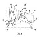
- FIG. 6is a schematic view of an airbag system and a vehicle occupant protection system incorporating a gas generating system including an end closure assembly in accordance with an embodiment of the present invention.
- FIG. 1is an exploded view of an end closure sub-assembly 10 in accordance with an embodiment of the present invention.
- FIG. 2is an assembled view of the end closure sub-assembly shown in FIG. 1 .
- Sub-assembly 10includes an end closure 12 configured for attachment to a housing 52 (see FIG. 5 ) of a gas generating system for closing and/or sealing the housing, and an initiator retainer 14 attached to end closure 12 .
- end closure 12has a first base portion 12 a and a first wall 12 b extending along a periphery of the first base portion 12 a .
- FIGS. 1is an exploded view of an end closure sub-assembly 10 in accordance with an embodiment of the present invention.
- FIG. 2is an assembled view of the end closure sub-assembly shown in FIG. 1 .
- Sub-assembly 10includes an end closure 12 configured for attachment to a housing 52 (see FIG. 5 ) of a gas
- a flange 12 cextends outwardly from wall 12 b .
- flange 12 cis not included.
- End closure base portion 12 aincludes an opening 12 d for receiving a portion of an associated initiator 18 therein.
- Base portion 12 amay alternatively include multiple openings 12 d for receiving multiple associated initiators therein; it will be appreciated that the openings 14 d in the second base portion 14 a (described below) will correspond to the number of openings 12 d.
- opening 12 dis provided in an initiator-receiving portion 12 e of base portion 12 a .
- Initiator-receiving portion 12 eis connected to base portion 12 a by a wall 12 f and extends from base portion 12 a in a direction toward an interior of the gas generating system when the end closure is attached to the system housing. This enables the terminals or contacts 28 of the initiator 18 to be recessed within the end closure as shown in FIG. 5 for protection.
- initiator-receiving portion 12 e and a first annular wall 12 fextend from a central portion of the end closure 12 .
- any initiator-receiving portion and its associated wallmay be spaced apart from the center of the end closure, depending on the design considerations and geometry of a particular gas generating system.
- Initiator-receiving portion 12 emay be fabricated using any suitable technique, depending on such factors as the materials from which the end closure is formed, the shape of the initiator-receiving portion, and other requirements of a particular application.
- end closure 12is formed from a metallic material and initiator-receiving portion 12 e and wall 12 f are drawn in the material.
- end closure 12is formed from a polymer material and initiator-receiving portion 12 e and wall 12 f are molded into the base portion 12 a.
- End closure 12may be formed form any suitable material (for example, a metal, metal alloy, or polymer) suitable for the requirements of a particular application.
- initiator retainer 14has a base portion 14 a including a formed portion or second annular wall 14 b extending in a direction toward an interior of the gas generating system when the end closure is attached to the system housing.
- Formed portion 14 bdefines an opening 14 d configured for receiving a portion of initiator 18 therein.
- the second annular wall 14 bis joined in nested relationship over first annular wall 12 f , respectively. Stated another way, as shown in the embodiment of FIGS.
- the shape of metallic initiator retainer 14substantially conforms to the shape of metallic end closure 12 , thereby facilitating nested relationship of retainer 14 over end closure 12 .
- the juxtaposed annular walls 14 b and 12 fform an annular wall 15 for containment, seating, and sealing of an initiator 18 , as described below.
- the initiator retainer 14may have any shape suitable for the requirements of a particular application.
- Embodiments of the initiator retainer 14include features which facilitate attachment of the initiator retainer 14 to the end closure 12 .
- retainer 14is secured to end closure 12 by projection welding together abutting sections of their respective base portions 14 a and 12 a .
- the overall wall thickness of the housingmay be substantially reduced by 35 to 40% of its original thickness, by virtue of the reinforced area of the welded base portions 12 a and 14 a .
- the wall thicknessmay be reduced from a typical thickness of about 2.2 millimeters to about 1.4 millimeters.
- the pressure vessel strengthis substantially enhanced, by essentially doubling the base material thickness, while minimizing the overall housing thickness required.
- Other base and housing thicknessesmay be iteratively determined, depending on the type of inflator, and depending on the ignition and gas generation chemistry employed.
- Other modes of attachmentare also contemplated depending on the geometries of the end closure 12 and the initiator retainer 14 , and other design, materials, and operational factors.
- initiator retainer 14is made from a metallic material and formed portion or second annular wall 14 b is fabricated by drawing a portion of the initiator retainer material in the direction shown.
- retainer 14can be made from any other suitable material (for example, a polymer).
- formed portion or second annular wall 14 bis provided in a central portion of the initiator retainer 14 .
- any formed portion(s) 14 b of the initiator retainermay alternatively be spaced apart from the center of the initiator retainer, depending on the design considerations and geometry of a particular gas generating system.
- Formed portion or second annular wall 14 bmay be stepped as shown in FIGS. 1 & 2 to meet processing requirements of the initiator retainer material (for example, in the case of a metallic retainer), to facilitate recessed mounting of the initiator as shown in FIG. 5 , or to meet other design requirements of a particular gas generating system.
- the initiator retainer materialfor example, in the case of a metallic retainer
- a wall 14 cextends along a periphery of the base portion 14 a , for engaging or helping to contain another element of the gas generating system.
- wall 14 cmay be omitted if desired.
- Initiator retainer 14may be formed from any suitable material, for example a metallic material or a polymer material.
- Initiator 18may be any suitable initiator known in the art.
- One exemplary initiator constructionis described in U.S. Pat. No. 6,009,809, incorporated herein by reference.
- a third annular wall 14 g contiguous with formed portion or second annular wall 14 bis structured to enable crimping of the wall 14 g over a portion of initiator 18 , to retain the initiator in the retainer 14 .
- Other methodsfor example, press-fitting or adhesive application) of securing the initiator to the retainer are also contemplated.
- a resilient seal 90(such as an o-ring seal) or other type of seal may be positioned between the initiator 18 and the retainer 14 to prevent the escape of generated gases through the initiator-retainer interface.
- a connector retainer 30may be incorporated into the end closure assembly for retaining a connector (not shown) coupled to the initiator terminals 28 when the gas generating system is installed in a vehicle or other device.
- the connectoroperatively couples the initiator 18 to a device or mechanism for actuating the initiator when the need for generated gases arises.
- System 50has a housing 52 , wherein the housing 52 is formed from a first housing portion or cap 54 and an end closure assembly or base 11 secured to the first housing portion 54 , so as to form a substantially hermetic seal between the first housing portion 54 and the end closure assembly 11 .
- Housing 52has one or more gas exit apertures 57 formed therein to enable fluid communication between an interior of the housing and an exterior of the housing upon activation of the gas generating system.
- a tube 26may be positioned within the gas generating system to enclose a portion of initiator 18 and for receiving a booster material 60 in an interior thereof.
- Tube 26is generally cylindrical and may be secured within housing 52 by welding or any other suitable method.
- Tube 26has at least one opening 91 formed therein to enable fluid communication between the interior of the tube and an exterior of the tube upon activation of the gas generating system.
- Tube 26may be extruded, roll formed, or otherwise metal formed and may be made from carbon steel, stainless steel, or any other suitable material.
- tube 26is formed from a thermally-conductive material to facilitate heat transfer between a heat-activated auto-ignition material (not shown) and a portion of the gas generating system housing in thermal contact with tube 26 and exposed to elevated temperatures occurring on the exterior of the housing, due to a fire for example. Ignition of the auto-ignition material produces ignition of booster material 60 or gas generant material in thermal communication with the auto-ignition material, in a manner known in the art.
- a plurality of annular gas generant wafers 62are stacked around and adjacent tube 26 .
- wafers 62are annular in shape and each wafer 62 has substantially the same dimensions.
- the wafersmay have any of a variety of alternative shapes positionable within cavity 28 .
- other, alternative forms of gas generantfor example, tablets
- gas generant compositions suitable for use in the embodiments of the present inventionare disclosed in U.S. Pat. Nos. 5,035,757, 6,210,505, and 5,872,329, incorporated herein by reference.
- the range of suitable gas generantsis not limited to that described in the cited patents.
- appropriately shaped pads or cushions 64may be provided at one or more ends of the stack of gas generant wafers 62 for holding the gas generant wafers in place and/or for cushioning the gas generant wafers against vibration and impact.
- Cushions 64may be formed from a ceramic fiber material, for example.
- Booster material 60may be positioned in tube 26 to facilitate combustion of gas generant 62 . Activation of initiator 18 produces combustion of the booster material, thereby effecting ignition of gas generant material 62 in a manner known in the art.
- a quantity of a known heat-activated auto-ignition materialmay be positioned within the gas generating system so as to enable fluid communication between the auto-ignition material and any associated gas generant material and/or any associated booster material upon activation of the gas generating system.
- the auto-ignition materialis a pyrotechnic material which is ignited by exposure to a temperature lower than the ignition temperature of the associated gas generant.
- the auto-ignition materialis ignited by heat transmitted from an exterior of the system housing to the interior of the housing due to an elevated external temperature condition (produced, for example, by a fire). Combustion of the auto-ignition material results in combustion of the associated gas generant, either directly or through intervening combustion of the booster material.
- Suitable auto ignition materialsare known to those skilled in the art. Examples of suitable auto-ignition materials are nitro-cellulose based compositions and gun powder.
- a filter 78may be incorporated into the inflator design for filtering particulates from gases generated by combustion of gas generant material 62 .
- filter 78is positioned between any gas generant material in the housing and any gas exit apertures 57 formed in housing 52 .
- filter 78is positioned between initiator retainer wall 14 c and a similar wall 80 b formed along a periphery of a filter retainer 80 and aligned with wall 14 c .
- Filter retainer 80is secured within housing 52 using any suitable method.
- the filtermay be formed from one of a variety of materials (for example, a carbon fiber mesh or sheet) known in the art for filtering gas generant combustion products.
- the gas generant material 62is ignited by activation of first initiator assembly 18 and the resulting ignition of booster material 30 . Gases resulting from the combustion of the gas generant flow through filter 78 , exiting the gas generating system through gas exit openings 57 .
- inflators or gas generators manufactured in accordance with the present inventionenjoy at least one or more of the following benefits.
- the present method of sealing an igniter within a gas generatorinherent within the end closure assembly described 11 herein, provides a relatively low-cost method of sealing the inflator.
- the relatively-expensive body bore sealis eliminated as is the relatively expensive and time-consuming structural weld necessitated when employing the body bore seal.
- the present end closure assembly 11may be adapted to various initiator and connector retainers, and therefore presents a broad solution to many types of inflators.
- the present end closure assemblypresents a relatively strong pressure vessel given the increased relative thickness of the base, a doubling of the base wall thickness for example.
- Airbag system 100comprises a housing 102 having a rupturable frontal closure 114 , an airbag 116 , and a gas generating system 50 in accordance with an embodiment of the present invention.
- Airbag system 100may include (or be in communication with) a crash event sensor 210 (for example, an inertia sensor or an accelerometer) including a known crash sensor algorithm that signals actuation of one or more of initiators 18 c and 20 c previously described.
- a crash event sensor 210for example, an inertia sensor or an accelerometer
- any embodiment of a gas generating system 50 incorporating the features described abovemay be incorporated into a broader, more comprehensive vehicle occupant protection system 180 including additional elements such as, for example, a safety belt assembly 150 .
- FIG. 6shows a schematic diagram of one exemplary embodiment of such a protection system.
- Safety belt assembly 150includes a safety belt housing 152 and a safety belt 225 in accordance with the present invention extending from housing 152 .
- a safety belt retractor mechanism 154(for example, a spring-loaded mechanism) may be coupled to an end portion of the belt.
- a safety belt pretensioner 156may be coupled to belt refractor mechanism 154 to actuate the retractor mechanism in the event of a collision.
- Typical seat belt retractor mechanismswhich may be used in conjunction with the safety belt embodiments of the present invention are described in U.S. Pat. Nos. 5,743,480, 5,553,803, 5,667,161, 5,451,008, 4,558,832 and 4,597,546, incorporated herein by reference.
- Illustrative examples of typical pretensioners with which the safety belt embodiments of the present invention may be combinedare described in U.S. Pat. Nos. 6,505,790 and 6,419,177, each incorporated herein by reference.
- Safety belt system 150may include (or be in communication with) a crash event sensor 158 (for example, an inertia sensor or an accelerometer) including a known crash sensor algorithm that signals actuation of belt pretensioner 156 via, for example, activation of a pyrotechnic igniter (not shown) incorporated into the pretensioner.
- a crash event sensor 158for example, an inertia sensor or an accelerometer
- a known crash sensor algorithmthat signals actuation of belt pretensioner 156 via, for example, activation of a pyrotechnic igniter (not shown) incorporated into the pretensioner.
- U.S. Pat. Nos. 6,505,790 and 6,419,177previously incorporated herein by reference, provide illustrative examples of pretensioners actuated in such a manner.
Landscapes
- Physics & Mathematics (AREA)
- Fluid Mechanics (AREA)
- Engineering & Computer Science (AREA)
- Mechanical Engineering (AREA)
- Air Bags (AREA)
Abstract
Description
- 1. Providing an annular
end closure plate 12 having a predetermined first annular wall shape; - 2. Providing an
annular igniter retainer 14 having a second annular wall shape substantially congruent to and conforming to the shape of the annularend closure plate 12; - 3. Overlaying the
end closure plate 12 with theannular igniter retainer 14 to juxtapose the second annular wall shape and the first annular wall shape; - 4. Welding or otherwise fixing the annular igniter retainer to the end closure plate;
- 5. Providing an annular seal for seating within the second annular wall shape;
- 6. Inserting an igniter through the juxtaposed first and second annular walls; And
- 7. Crimping or otherwise sealing the igniter within the annular igniter retainer.
It will be appreciated that the inflator is otherwise manufactured as known in the art and may for example, incorporate known gas generant, booster, and ignition compositions. Other structural features of the inflator may be made as known to one of ordinary skill in the art.
- 1. Providing an annular
Claims (11)
Priority Applications (2)
| Application Number | Priority Date | Filing Date | Title |
|---|---|---|---|
| US12/802,839US8393641B1 (en) | 2009-06-12 | 2010-06-14 | Gas generator |
| US13/792,894US9051225B1 (en) | 2009-06-12 | 2013-03-11 | Gas generator |
Applications Claiming Priority (2)
| Application Number | Priority Date | Filing Date | Title |
|---|---|---|---|
| US26842309P | 2009-06-12 | 2009-06-12 | |
| US12/802,839US8393641B1 (en) | 2009-06-12 | 2010-06-14 | Gas generator |
Related Child Applications (1)
| Application Number | Title | Priority Date | Filing Date |
|---|---|---|---|
| US13/792,894Continuation-In-PartUS9051225B1 (en) | 2009-06-12 | 2013-03-11 | Gas generator |
Publications (1)
| Publication Number | Publication Date |
|---|---|
| US8393641B1true US8393641B1 (en) | 2013-03-12 |
Family
ID=47780390
Family Applications (1)
| Application Number | Title | Priority Date | Filing Date |
|---|---|---|---|
| US12/802,839Expired - Fee RelatedUS8393641B1 (en) | 2009-06-12 | 2010-06-14 | Gas generator |
Country Status (1)
| Country | Link |
|---|---|
| US (1) | US8393641B1 (en) |
Cited By (5)
| Publication number | Priority date | Publication date | Assignee | Title |
|---|---|---|---|---|
| US8936272B1 (en) | 2012-04-09 | 2015-01-20 | Tk Holdings Inc. | Gas generating system |
| US9051225B1 (en) | 2009-06-12 | 2015-06-09 | Tk Holdings Inc. | Gas generator |
| JP2015157520A (en)* | 2014-02-21 | 2015-09-03 | タカタ株式会社 | Gas generator |
| US10330261B2 (en)* | 2016-11-29 | 2019-06-25 | Goodrich Corporation | System and method for a heated gas cylinder assembly |
| US20200374986A1 (en)* | 2019-05-20 | 2020-11-26 | Toshiba Lighting & Technology Corporation | Heater |
Citations (29)
| Publication number | Priority date | Publication date | Assignee | Title |
|---|---|---|---|---|
| US1401810A (en) | 1919-07-14 | 1921-12-27 | Morris George Ernest | Automatic filter |
| US3672301A (en) | 1969-12-31 | 1972-06-27 | Aai Corp | Cartridge |
| US3990367A (en) | 1975-06-16 | 1976-11-09 | The United States Of America As Represented By The Secretary Of The Navy | Injection-molding apparatus for attaching end fittings to detonating cords |
| US4278638A (en) | 1979-04-14 | 1981-07-14 | Messerschmitt-Bolkow-Blohm Gmbh | Gas generator construction |
| US4530516A (en) | 1984-07-09 | 1985-07-23 | Morton Thiokol Inc. | Aluminum inflator with steel center-tie |
| US4722551A (en) | 1987-03-19 | 1988-02-02 | Morton Thiokol, Inc. | Initiator and method for the incorporation thereof in an inflator |
| US5131679A (en) | 1990-12-18 | 1992-07-21 | Trw Inc. | Initiator assembly for air bag inflator |
| US5711531A (en) | 1993-10-20 | 1998-01-27 | Quantic Industries, Inc. | Electrical initiator seal |
| US5779268A (en)* | 1995-06-06 | 1998-07-14 | Morton International, Inc. | Stamped driver inflator base |
| US5890735A (en)* | 1997-01-13 | 1999-04-06 | Morton International Inc. | Hybrid inflator with diffuser end translating initiator boss |
| US6056314A (en) | 1998-02-20 | 2000-05-02 | Trw Inc. | Initiator retainer for air bag inflator |
| US6068291A (en) | 1997-05-23 | 2000-05-30 | Livbag Snc | Adaptive pyrotechnic gas generator with tubular chambers, for airbags |
| US6073963A (en) | 1998-03-19 | 2000-06-13 | Oea, Inc. | Initiator with injection molded insert member |
| US6341562B1 (en) | 2000-02-22 | 2002-01-29 | Autoliv Asp, Inc. | Initiator assembly with activation circuitry |
| US20020017778A1 (en)* | 1996-04-08 | 2002-02-14 | Nobuyuki Katsuda | Airbag inflator and an airbag apparatus |
| US6491320B1 (en) | 1998-09-28 | 2002-12-10 | Daicel Chemical Industries, Ltd. | Air bag gas generator and air bag apparatus |
| US6644198B1 (en) | 2000-10-31 | 2003-11-11 | Special Devices, Inc. | Integral pyrotechnic initiator with molded connector |
| US6722694B1 (en)* | 1999-02-16 | 2004-04-20 | Daicel Chemical Industries, Ltd. | Gas generator for multi-stage air bag and air bag device |
| US6763764B2 (en) | 2000-10-31 | 2004-07-20 | Special Devices, Inc. | Multi-unit pyrotechnic initiation system |
| US6820556B1 (en) | 2001-11-21 | 2004-11-23 | Daicel Chemical Industries, Ltd. | Initiator assembly |
| US6823796B1 (en) | 1999-10-14 | 2004-11-30 | Nippon Kayaku Kabushiki Kaisha | Gas generator |
| US6840977B1 (en) | 1999-07-14 | 2005-01-11 | Daicel Chemical Industries, Ltd. | Coolant for air-bag gas generator and production method therefor |
| US6871871B2 (en)* | 2002-09-13 | 2005-03-29 | Island Pyrochemical Industries Corp. | Air bag inflator |
| US7111558B2 (en) | 2002-02-09 | 2006-09-26 | Delphi Technologies, Inc. | Pyrotechnic detonator with an igniter support of plastic with an integrated metal insert |
| US7185588B2 (en)* | 2003-12-05 | 2007-03-06 | Autoliv Asp, Inc. | Inflator devices having a moisture barrier member |
| US7540241B2 (en) | 2005-05-13 | 2009-06-02 | Trw Airbag Systems Gmbh | Gas generator |
| US7854201B2 (en) | 2005-11-08 | 2010-12-21 | Daicel Chemical Industries, Ltd. | Igniter assembly |
| US20110088583A1 (en)* | 2008-12-04 | 2011-04-21 | Morgan Richard W | Gas Generating System |
| US20110221176A1 (en) | 2008-12-03 | 2011-09-15 | Sebastian Bierwirth | Gas generator |
- 2010
- 2010-06-14USUS12/802,839patent/US8393641B1/ennot_activeExpired - Fee Related
Patent Citations (31)
| Publication number | Priority date | Publication date | Assignee | Title |
|---|---|---|---|---|
| US1401810A (en) | 1919-07-14 | 1921-12-27 | Morris George Ernest | Automatic filter |
| US3672301A (en) | 1969-12-31 | 1972-06-27 | Aai Corp | Cartridge |
| US3990367A (en) | 1975-06-16 | 1976-11-09 | The United States Of America As Represented By The Secretary Of The Navy | Injection-molding apparatus for attaching end fittings to detonating cords |
| US4278638A (en) | 1979-04-14 | 1981-07-14 | Messerschmitt-Bolkow-Blohm Gmbh | Gas generator construction |
| US4530516A (en) | 1984-07-09 | 1985-07-23 | Morton Thiokol Inc. | Aluminum inflator with steel center-tie |
| US4722551A (en) | 1987-03-19 | 1988-02-02 | Morton Thiokol, Inc. | Initiator and method for the incorporation thereof in an inflator |
| US5131679A (en) | 1990-12-18 | 1992-07-21 | Trw Inc. | Initiator assembly for air bag inflator |
| US5711531A (en) | 1993-10-20 | 1998-01-27 | Quantic Industries, Inc. | Electrical initiator seal |
| US6044557A (en)* | 1995-06-06 | 2000-04-04 | Autoliv Asp, Inc. | Method of making stamped driver inflator base |
| US5779268A (en)* | 1995-06-06 | 1998-07-14 | Morton International, Inc. | Stamped driver inflator base |
| US20020017778A1 (en)* | 1996-04-08 | 2002-02-14 | Nobuyuki Katsuda | Airbag inflator and an airbag apparatus |
| US5890735A (en)* | 1997-01-13 | 1999-04-06 | Morton International Inc. | Hybrid inflator with diffuser end translating initiator boss |
| US6068291A (en) | 1997-05-23 | 2000-05-30 | Livbag Snc | Adaptive pyrotechnic gas generator with tubular chambers, for airbags |
| US6056314A (en) | 1998-02-20 | 2000-05-02 | Trw Inc. | Initiator retainer for air bag inflator |
| US6073963A (en) | 1998-03-19 | 2000-06-13 | Oea, Inc. | Initiator with injection molded insert member |
| US6491320B1 (en) | 1998-09-28 | 2002-12-10 | Daicel Chemical Industries, Ltd. | Air bag gas generator and air bag apparatus |
| US6557888B1 (en) | 1998-09-28 | 2003-05-06 | Daicel Chemical Industries, Ltd. | Air bag gas generator and air bag apparatus |
| US6722694B1 (en)* | 1999-02-16 | 2004-04-20 | Daicel Chemical Industries, Ltd. | Gas generator for multi-stage air bag and air bag device |
| US6840977B1 (en) | 1999-07-14 | 2005-01-11 | Daicel Chemical Industries, Ltd. | Coolant for air-bag gas generator and production method therefor |
| US6823796B1 (en) | 1999-10-14 | 2004-11-30 | Nippon Kayaku Kabushiki Kaisha | Gas generator |
| US6341562B1 (en) | 2000-02-22 | 2002-01-29 | Autoliv Asp, Inc. | Initiator assembly with activation circuitry |
| US6763764B2 (en) | 2000-10-31 | 2004-07-20 | Special Devices, Inc. | Multi-unit pyrotechnic initiation system |
| US6644198B1 (en) | 2000-10-31 | 2003-11-11 | Special Devices, Inc. | Integral pyrotechnic initiator with molded connector |
| US6820556B1 (en) | 2001-11-21 | 2004-11-23 | Daicel Chemical Industries, Ltd. | Initiator assembly |
| US7111558B2 (en) | 2002-02-09 | 2006-09-26 | Delphi Technologies, Inc. | Pyrotechnic detonator with an igniter support of plastic with an integrated metal insert |
| US6871871B2 (en)* | 2002-09-13 | 2005-03-29 | Island Pyrochemical Industries Corp. | Air bag inflator |
| US7185588B2 (en)* | 2003-12-05 | 2007-03-06 | Autoliv Asp, Inc. | Inflator devices having a moisture barrier member |
| US7540241B2 (en) | 2005-05-13 | 2009-06-02 | Trw Airbag Systems Gmbh | Gas generator |
| US7854201B2 (en) | 2005-11-08 | 2010-12-21 | Daicel Chemical Industries, Ltd. | Igniter assembly |
| US20110221176A1 (en) | 2008-12-03 | 2011-09-15 | Sebastian Bierwirth | Gas generator |
| US20110088583A1 (en)* | 2008-12-04 | 2011-04-21 | Morgan Richard W | Gas Generating System |
Cited By (6)
| Publication number | Priority date | Publication date | Assignee | Title |
|---|---|---|---|---|
| US9051225B1 (en) | 2009-06-12 | 2015-06-09 | Tk Holdings Inc. | Gas generator |
| US8936272B1 (en) | 2012-04-09 | 2015-01-20 | Tk Holdings Inc. | Gas generating system |
| JP2015157520A (en)* | 2014-02-21 | 2015-09-03 | タカタ株式会社 | Gas generator |
| US10330261B2 (en)* | 2016-11-29 | 2019-06-25 | Goodrich Corporation | System and method for a heated gas cylinder assembly |
| US20200374986A1 (en)* | 2019-05-20 | 2020-11-26 | Toshiba Lighting & Technology Corporation | Heater |
| US11729866B2 (en)* | 2019-05-20 | 2023-08-15 | Toshiba Lighting & Technology Corporation | Heater |
Similar Documents
| Publication | Publication Date | Title |
|---|---|---|
| US7806954B2 (en) | Gas generator | |
| US8376400B2 (en) | Gas generating system | |
| EP1837253B1 (en) | Gas generator for occupant restraining device for vehicle | |
| EP2426015A1 (en) | Gas generator | |
| US9051226B2 (en) | Gas generating system | |
| US8240709B1 (en) | Multi-chamber gas generating system | |
| EP0841225A1 (en) | Gas generator for air bag and air bag system | |
| US7568728B2 (en) | Inflator device having modular construction and radial inflation gas flow | |
| US8393641B1 (en) | Gas generator | |
| US8172262B2 (en) | Initiator housing assembly | |
| CN103347744A (en) | Gas generator | |
| JPH1159314A (en) | Gas generator for air bag | |
| KR101722806B1 (en) | Gas generator and method for assembling same | |
| JP2008296763A (en) | Gas generator | |
| US9051225B1 (en) | Gas generator | |
| US6116643A (en) | Coolant/filter for air bag gas generator | |
| JP2009286218A (en) | Gas generator | |
| US8496266B2 (en) | Gas generating system | |
| US8820783B1 (en) | Gas generating system | |
| JP2013063780A (en) | Gas generator | |
| US9321426B1 (en) | Container for gas generant | |
| JP4912942B2 (en) | Gas generator | |
| US9550471B1 (en) | Gas generating system movable divider | |
| US7802812B2 (en) | Gas generating system | |
| JP5219196B2 (en) | Gas generator and filter for gas generator |
Legal Events
| Date | Code | Title | Description |
|---|---|---|---|
| AS | Assignment | Owner name:TK HOLDINGS, INC., MICHIGAN Free format text:ASSIGNMENT OF ASSIGNORS INTEREST;ASSIGNOR:QUIOC, EDUARDO L.;REEL/FRAME:024684/0576 Effective date:20100610 | |
| STCF | Information on status: patent grant | Free format text:PATENTED CASE | |
| FPAY | Fee payment | Year of fee payment:4 | |
| AS | Assignment | Owner name:DEUTSCHE BANK TRUST COMPANY AMERICAS, NEW YORK Free format text:INTELLECTUAL PROPERTY SECURITY AGREEMENT SUPPLEMENT;ASSIGNOR:JOYSON SAFETY SYSTEMS ACQUISITION LLC;REEL/FRAME:045959/0305 Effective date:20180410 | |
| CC | Certificate of correction | ||
| AS | Assignment | Owner name:JOYSON SAFETY SYSTEMS ACQUISITION LLC, MICHIGAN Free format text:ASSIGNMENT OF ASSIGNORS INTEREST;ASSIGNOR:TK HOLDINGS INC.;REEL/FRAME:046173/0180 Effective date:20180410 | |
| FEPP | Fee payment procedure | Free format text:MAINTENANCE FEE REMINDER MAILED (ORIGINAL EVENT CODE: REM.); ENTITY STATUS OF PATENT OWNER: LARGE ENTITY | |
| LAPS | Lapse for failure to pay maintenance fees | Free format text:PATENT EXPIRED FOR FAILURE TO PAY MAINTENANCE FEES (ORIGINAL EVENT CODE: EXP.); ENTITY STATUS OF PATENT OWNER: LARGE ENTITY | |
| STCH | Information on status: patent discontinuation | Free format text:PATENT EXPIRED DUE TO NONPAYMENT OF MAINTENANCE FEES UNDER 37 CFR 1.362 | |
| FP | Lapsed due to failure to pay maintenance fee | Effective date:20210312 | |
| AS | Assignment | Owner name:JOYSON SAFETY SYSTEMS ACQUISITION LLC, MICHIGAN Free format text:RELEASE BY SECURED PARTY;ASSIGNOR:DEUTSCHE BANK TRUST COMPANY AMERICAS, AS SECURITY AGENT FOR THE SECURED PARTIES;REEL/FRAME:057775/0726 Effective date:20211004 |