Movatterモバイル変換


[0]ホーム

URL:


US8393319B2 - Domestic appliance door and pertaining operational module - Google Patents

Domestic appliance door and pertaining operational module
Download PDF

Info

Publication number
US8393319B2
US8393319B2US12/086,676US8667606AUS8393319B2US 8393319 B2US8393319 B2US 8393319B2US 8667606 AUS8667606 AUS 8667606AUS 8393319 B2US8393319 B2US 8393319B2
Authority
US
United States
Prior art keywords
door
panel
recess
operating module
operating
Prior art date
Legal status (The legal status is an assumption and is not a legal conclusion. Google has not performed a legal analysis and makes no representation as to the accuracy of the status listed.)
Expired - Fee Related, expires
Application number
US12/086,676
Other versions
US20090032010A1 (en
Inventor
Dirk Hoffmeier
Current Assignee (The listed assignees may be inaccurate. Google has not performed a legal analysis and makes no representation or warranty as to the accuracy of the list.)
BSH Hausgeraete GmbH
Original Assignee
BSH Bosch und Siemens Hausgeraete GmbH
Priority date (The priority date is an assumption and is not a legal conclusion. Google has not performed a legal analysis and makes no representation as to the accuracy of the date listed.)
Filing date
Publication date
Application filed by BSH Bosch und Siemens Hausgeraete GmbHfiledCriticalBSH Bosch und Siemens Hausgeraete GmbH
Publication of US20090032010A1publicationCriticalpatent/US20090032010A1/en
Assigned to BSH BOSCH UND SIEMENS HAUSGERAETE GMBHreassignmentBSH BOSCH UND SIEMENS HAUSGERAETE GMBHASSIGNMENT OF ASSIGNORS INTEREST (SEE DOCUMENT FOR DETAILS).Assignors: HOFFMEIER, DIRK
Application grantedgrantedCritical
Publication of US8393319B2publicationCriticalpatent/US8393319B2/en
Assigned to BSH Hausgeräte GmbHreassignmentBSH Hausgeräte GmbHCHANGE OF NAME (SEE DOCUMENT FOR DETAILS).Assignors: BSH Bosch und Siemens Hausgeräte GmbH
Assigned to BSH Hausgeräte GmbHreassignmentBSH Hausgeräte GmbHCORRECTIVE ASSIGNMENT TO REMOVE USSN 14373413; 29120436 AND 29429277 PREVIOUSLY RECORDED AT REEL: 035624 FRAME: 0784. ASSIGNOR(S) HEREBY CONFIRMS THE CHANGE OF NAME.Assignors: BSH Bosch und Siemens Hausgeräte GmbH
Expired - Fee Relatedlegal-statusCriticalCurrent
Adjusted expirationlegal-statusCritical

Links

Images

Classifications

Definitions

Landscapes

Abstract

An operational module for a domestic appliance door including at least one operational control received therein, wherein the operational module is configured for at least partial insertion into a recess of the domestic appliance door from the exterior. An operational module for a domestic appliance door, including at least two operational controls received therein, wherein the operational module is configured for at least partial insertion into a recess of the domestic appliance door. A domestic appliance door, especially an oven door, comprises at least one recess for at least partially accommodating at least one of the operational modules.

Description

The invention relates to an operating module for a door of a domestic appliance, in particular of a cooking appliance, a corresponding domestic appliance door and also a domestic appliance with the door.
A switchable glass door for domestic appliances is known from DE 297 22 024 U1, in which a ‘glass keyboard’ is integrated onto or into the glass door. In this situation, the control panel is the transparent glass door itself. The glass keyboard can include an LCD display or a monitor. An operating panel can be dispensed with. The evaluation electronics required for the operating unit are fitted in a temperature-reduced, insulated area of the oven. The disadvantage in this situation is the comparatively complex manufacturing process and repair capability. Moreover, as a result of the electronics the usability is disadvantageous in particular for users having poor sight or a restricted haptic capability. Also, in particular the longevity of the electrical and thin-film components is not guaranteed.
Push-type switch elements are likewise known from DE 299 19 792 U1, whose operating interface is formed from a glass sheet.
A microwave oven is known from DE 30 37 277 A1, in which electrically controllable operating facilities which can be operated by hand are mounted on the door. To this end the publication discloses key fields situated behind a front surface of a door, which in accordance with this appliance can advantageously extend up to just before the oven space opening. Since the door takes up the entire front elevation, a separate operating panel can be dispensed with.
A microwave oven is known fromDE 38 29 913 A1, in which switching, setting and/or display means are built into the cooking space door and this is implemented behind a front viewing panel.
DE 201 03 517 U1 describes a cooking appliance with a functionalized cooking appliance door whereby contacts are applied to the door in the form of films and in particular displays can be projected onto the at least partially transparent door, for example as in the case of a so-called head-up display. The display and/or operating element can also be mounted in a detachable manner on the cooking appliance door.
An oven door with operating elements integrated into a handle is known from WO 97/26486.
A cooking appliance door is known fromEP 1 120 606 A2, which has operating switches and display fields distributed in its door, which terminate flush with the front side. This is comparatively complex to manufacture and to wire up.
The object of the invention is to provide a capability enabling the simple and inexpensive manufacture and also the simple fitting and easy maintenance of operating elements.
The object is achieved by operating modules as claimed inclaims1 or2, a domestic appliance door as claimed inclaim10 and a domestic appliance as claimed inclaim18. Advantageous embodiments are set down individually or in combination in particular in the subclaims.
An operating module has at least one operating element incorporated in it, in other words a switch element and/or a display element, and can be at least partially inserted into a recess of a cooking appliance door from the outside.
Compared with the operating elements mounted on or in the door interior (from the viewpoint of the domestic appliance), this operating module has the advantage that the thickness of the door can be reduced because one part of the operating module can remain protruding externally. Also, compared with such known operating elements, a greater variation of switches and switch embodiments is possible; compared with behind-glass switches in particular it is also possible to use other switches—which offer better operation—such as knobs, rocker switches and so forth. Compared with switches mounted from the inside, which are taken through the outer side or front elevation of the door, this yields the special advantage that the external operating part of the operating module does not need to be matched precisely to the size of the recess but can be independent of it. Compared with control units mounted on the door, this yields the advantage of a more reliable mounting, for example by means of clamping on or pushing into the door, a less protruding construction and a simpler connection to other appliance components, a power supply for example.
These advantages apply in particular if the operating module comprises more than one operating element, whereby this then yields the further advantage of a simplified manufacturing process, a simplified installation and an easier repair capability.
In this situation, an operating module can be a defined assembly or functional group, which forms a part of a whole and can be modified or replaced without requiring intervention or changes in the remainder of the system (c.f. Bibliographisches Institut & F. A. Brockhaus A G, Mannheim; Spektrum Akademischer Verlag GmbH, Heidelberg, 2003); this can advantageously be a housing, which can be separated from the domestic appliance door, with at least the operating element/operating elements installed therein.
Another operating module which achieves the object has at least two operating elements, which can be inserted at least partially into a recess in a cooking appliance door.
This operating module has the advantage compared with distributed, individual operating elements that it requires fewer and simpler installation steps and can be more simply replaced. Compared with elements arranged behind the door front, this yields the advantage of a possible reduction in installation height for the door itself since the housing can protrude outwards; furthermore, a greater variety of switch elements (knobs, rocker switches) is possible, which can also offer better operation. Compared with control units mounted on the door, this yields the advantage of a more reliable mounting, for example by means of clamping on the door, a less protruding construction and a simpler connection to other appliance components, a power supply for example.
Apart from operating elements, in other words switch elements (switches, knobs, keys, sliders etc.) and/or display elements (LED displays, alphanumeric displays such as LCD full pixel fields etc.), the operating module can advantageously also have an associated electrical system and/or electronics and also suitable communication means for the purpose of data transfer with other components, for example cables, cable connections, evaluation and/or control electronics, wireless transfer devices or similar.
In order to reduce thermal absorption from the door or from an interior space of the domestic appliance—for example a cooking space—the operating module in question advantageously has an (from the viewpoint of the domestic appliance) outward protruding part which, after being fitted into the door, protrudes outwards from the door surface, and also a part which can be inserted into the recess. As a result it is also possible to reduce the thickness or installation depth of the door and improved usability can be achieved.
In this situation, it is advantageous if the insertable part of the operating module accommodates electrical and/or electronic components in particular, whereas the outward protruding part includes the operating elements in particular. By means of such an arrangement it is possible to provide a large control panel which can also extend sideways (upwards, downwards, to the left and/or right in a top view of the door) over the recess, while the recess itself can be kept advantageously small with regard to heat insulation.
The provision of a (in a top view of the door) part of the operating module protruding sideways over the recess or the part of the operating module which can be inserted into the recess can be generally advantageous for reasons of heat dissipation and better usability.
For reasons of sealing the interior of the door against its surroundings it is advantageous if the part protruding sideways (in other words to the left, right, upwards and/or downwards) over the recess can be fitted on a front door panel, for example an external or front sheet, of the domestic appliance door, in particular with a seal.
In order to further seal a side edge of the appliance door, in particular with recesses open to the side, it is advantageous if the operating module has a cover plate which can be fitted in order to cover at least one part, preferably the part opened by the recess, of a side edge of the domestic appliance door. In this situation, it is also advantageous if a seal with the side edge of the appliance door is present in the area of the cover plate.
It can be advantageous, for example for the purpose of simpler replacement and improved mounting of the operating module, if the cover plate protrudes in a lateral direction over the area of the (upper, lower, left-hand and/or right-hand) side edge bordering with it.
The aforementioned applies in particular to doors which cover one side of the domestic appliance without the use of an operating panel. Optimizing the heat insulation is particularly advantageous for doors having—possibly apart from a narrow border—a fully glazed surface.
In order to optimize the function of the operating module it is advantageous if the majority of the operating elements, in particular all the operating elements, are accommodated in a single operating module. Then only a single recess in the door is required and thus only one insertion and mounting operation. Any repair also becomes more convenient through replacement of the entire operating module.
The object is also achieved by a domestic appliance door, in particular a cooking appliance door, specifically an oven door, having at least one recess for receiving at least one of the operating modules described above in each case, into which one operating module can be inserted. The door can in particular be a door for cooking appliances, in particular for ovens.
It is advantageous if the operating module is inserted partially into the recess in the door and protrudes partially outwards. Advantageously, the insertable part of the operating module in particular accommodates electrical and/or electronic components, while the part protruding outwards in particular includes the operating elements.
The recess can be inserted into the domestic appliance door at different depths, depending on requirements. In order to minimize the effect of a recess on an appliance door, only the front door panel, for example the front sheet, needs to be provided with the recess. According to requirements, for example the internal structure of the door, the design of the operating module or cooling requirements, the recess can also be taken through further door elements, for example further door sheets, dividing walls or insulation areas. In this situation, it is also possible that the recess is taken right through the entire appliance door such that the operating module can be fitted right through the door with its part which can be inserted into the recess.
The recess can for example comprise or constitute a cutout open to the side at least in the front door panel; this is advantageous for the purpose of simpler assembly. Alternatively, the recess can be surrounded on all sides by material at least of the front panel. The recess can also be open to the side on two sides. It is also possible for the recess to be formed differently in different layers of the door, for example a recess open to the side in the front sheet and as an enclosed recess in a sheet lying behind.
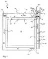
The part protruding outwards can also overlap laterally in any direction (in other words to the left, to the right, upwards and/or downwards) over the part to be inserted into the recess.
It is particularly advantageous—in particular for doors closing a cooking space—if the operating module can be inserted into an area, referred to in the following as the operating module receiving area, which is separated thermally from a part of the door situated directly opposite the cooking space.
The thermal separation can be effected for example by means of dividing walls such as sheeting, films, insulating material and so forth. Alternatively, in the area between the operating module receiving area and the area of the appliance door situated opposite the appliance interior space, at least one outlet ventilation hole can be incorporated in the area situated opposite the appliance interior space, such that warm air can be dissipated there and does not accumulate at the operating module receiving area. This is particularly advantageous in the case of doors having ventilation of the door interior space. It is furthermore advantageous for the purpose of thermal insulation if the operating module receiving area can be ventilated directly or indirectly, specifically with cooling air.
It is advantageous for the purpose of effective ventilation, in particular when separating the areas for cooling air inlet and discharged air outlet, if the ventilatable operating module receiving area is arranged away from the discharged air outlet, for example at an opposite side of the domestic appliance, for example such that the operating module receiving area is arranged above the cooking space and the discharged air outlet is arranged beneath the cooking space, or vice versa. To this end, it is also advantageous if at least some air inlet openings are arranged at the side of the door.
It can also be advantageous if the door has a full glass front, into which the recess is incorporated. Particularly in the case of a full glass door it is advantageous if the door handle is integrated at the side in the door.
The object is also achieved by a domestic appliance, in particular a cooking appliance, which has a door as described above having at least one operating module as described above suitable for use. This applies in particular to domestic appliances without a separate operating panel.
The invention will be described in the following with reference to exemplary embodiments shown in the schematic figures. These exemplary embodiments do not restrict the invention which is determined by the scope of the claims. The same parts are identified by the same reference characters throughout.
FIG. 1 shows an oblique view in sketch form from outside of a built-in oven with an operating module;
FIG. 2 shows a schematic sectional side view of a further oven with an operating module;
FIG. 3 shows an oblique view of the front side of the operating module fromFIGS. 1 and 2;
FIG. 4 shows an oblique view of the rear side of the operating module fromFIGS. 1 to 3;
FIG. 5 shows a sectional side view of the operating module fromFIGS. 1 to 4;
FIG. 6 shows an oblique view of the front side of an operating element;
FIG. 7 shows a schematic sectional side view of a further oven with an operating module;
FIG. 8 shows a schematic top view of the front side illustrating a plurality of options for the design of the oven door.
FIG. 1 shows anoven door1 of an oven, into which anoperating module2 has been inserted. Theoven door1 covers the front side of the oven completely, such that the latter does not need to have a separate operating panel. Theoven door1 has at its outer side or front side a fullouter glass sheet4 held only by anarrow metal frame3. For thermal insulation purposes theoven door1 furthermore has aninner glass sheet5, as a result of which a door interior space is formed between thesheets4,5. It is also possible for further glass sheets to be present parallel to these. Inserted in this door interior space is apanel6 which, amongst other things, serves as visual protection and to provide airflow guidance. A viewing window is defined by means of acutout7 in thepanel6.Inlet ventilation slots8 are incorporated in the lower part of thepanel6 to provide a fresh-air feed. The upper outlet ventilation slots are not shown here. Theoven door1 can be opened and closed at the side by means of thehandle9.
FIG. 2 shows anoven10 with anoperating module2, the same and in the same position as inFIG. 1, in vertical section through theoperating module2. Thecooking space11 of theoven10 is delimited by amuffle12 open to the front, which is covered by an insulatinglayer13. Between the insulatinglayer13 and anouter oven panel14 is situated aflow space15 through which air can flow, and indeed this is preferably moved essentially by afan16 in the form of a cross-flow fan. Theoven door1 is included in the cooling-air circulation, in particular as a result of the fact that in this exemplary embodiment theoven door1 can be ventilated with fresh air through side openings, as indicated schematically by the arrows P1. The fresh air flowing thus into the ventilatable doorinterior space17 is heated up and flows upwards as a result of thermal convection and where applicable by means of suction exerted by thefan16, as indicated by the arrows P2. In the upper area of thecooking appliance door1 are situated dooroutlet ventilation slots18, through which the warmed-up air then exits thecooking appliance door1. Drawn in by thefan16, the air then continues to flow around thecooking space11 circulating in the flow space15 (as indicated by the arrows P3) until it exits theoven10 through lower ovenoutlet ventilation openings19. The associated heating elements etc. are not shown for the sake of improved clarity.
In this embodiment, in the cooking appliance oroven door1 above thecooking space11 and the dooroutlet ventilation openings18 is situated an operatingmodule receiving area20 in which a rear part of theoperating module2 is inserted into a recess. The operatingmodule receiving area20 is separated from the area21 of thecooking appliance door1 situated opposite thecooking space11 by arail22 and is by this means at least partially thermally separated or decoupled. As a result, the operatingmodule receiving area20 is comparatively cooler than the area21 located opposite thecooking space11.
Compared with the door area21 or door interior17 situated opposite thecooking space11, the operatingmodule receiving area20 continues to be maintained at a cooler temperature and is thermally separated by means of the fact that the hot air, as indicated by the arrows P2, is taken away from the area at the operatingmodule receiving area20 through the door outlet ventilation opening(s)18.
In addition, for the purpose of further thermal separation or decoupling and thus relative cooling of the operatingmodule receiving area20, at its rear side in the upper side of thecooking appliance door1 at least oneinlet ventilation opening23 leading to theflow space15 is present. As a result of the ambient air flowing through thisinlet ventilation opening23 into theflow space15 the operatingmodule receiving area20 and thus theoperating module2 are cooled further from the rear and the air temperature in theflow space15 drops at the same time.
The arrangement shown here also has the advantage that the air inlet openings in particular to the side in thedoor1 and at the top behind thecooking appliance door1 are separated spatially from theoven outlet openings19 such that, firstly, the fresh air is sufficiently cool and, secondly, no vapor expelled from thecooking space11 out of avapor opening24 can enter the ventilation circulation, which otherwise could result in soiling of the doorinterior space17 which could only be cleaned with difficulty.
Theoperating module2 has apart25 inserted into a recess open at the top of the front glass elevation and apart26 protruding outwards and forwards which additionally extends to the side downwards over the recess. Operating elements not shown here are present on the externally protrudingpart26.
FIG. 3 shows theoperating module2 fromFIGS. 1 and 2 in more detail obliquely from the front. In acommon housing33 theoperating module2 comprises a display unit in the form of a pixel-drivenLCD display27, at each side of which are placed three touch-sensitive keys28. TheLCD display27 and thekeys28 are covered by acommon plastic sheet31. To the side beneath theLCD display27 are situated tworotary knobs29 as further switches. Theknobs29 are also situated to the sides beneath thearea25 to be inserted into the recess on the externally protrudingpart26. At the upper edge theoperating module2 has anupper cover plate48.
FIG. 4 shows theoperating module2 fromFIGS. 1 to 3 obliquely from the rear. Thepart25 to be inserted into the recess here showselectrical connections30 as anelectronics receiving area50. Aseal51 running round the rear edge area can be clearly seen. In the area of the rotary switches29 theseal51 bears on the front door elevation and seals the door interior and theoperating module2 from their surroundings. In the upper, rear edge area which is covered here by theupper cover plate48 theseal51 runs just below thecover plate48, as also shown further below inFIG. 5.
For the purpose of mounting on theappliance door1, theoperating module2 has amongst other things twoscrew threads49 integrated with thehousing33, into which mounting screws (not shown) or similar can be screwed.
FIG. 5 shows theoperating module2 fromFIGS. 1 to 4 in a sectional side view along the line I-I fromFIG. 3, installed in acooking appliance door1. The protrudingarea26 can be seen, as indicated by the arrow pointing to the right, as can also thepart25 which can be inserted into arecess54 in theouter sheet4, as indicated by the arrow pointing to the left. The protrudingpart26 comprises the operating elements such as theknobs29, theLCD display27 fitted behind a plasticprotective sheet31, and the touch-sensitive keys (not shown), which are all accommodated in acommon housing33. Thepart25 which can be inserted into therecess54 comprises anelectronics unit32 for evaluating the signals from the operatingelements29; also present there is aloudspeaker34 driven by theelectronics unit32, for example for generating clicking sounds when theknobs29 are rotated.
It can be clearly seen that thepart53, which is associated with the outwards protrudingpart26 of theoperating module2 and protrudes to the side and downwards over therecess54 and which is indicated by the associated arrow, bears on theouter sheet4 with theseal51. The rotary switches29 are thus likewise supported on the front door elevation, if applicable with a slight gap.
It can also be seen that theupper cover plate48 covers a part of the side edge of thecooking appliance door1 and also seals it by means of theseal51. Thecover plate48 protrudes upwards over the adjoining upper side edge of thecooking appliance door1, which is formed in this cutout by anedge lip52.
Therecess54 into which theoperating module2 is inserted is included only in theouter glass sheet4; asecond glass sheet5 situated behind has no recess for receiving theoperating module2. Therecess54 here is a recess which is open to the side upwards.
The operatingmodule receiving space20, which is closed by theoperating module2, is defined by theouter glass sheet4, the second,inner glass sheet5, theedge lip52 and the dividingwall22 provided for the purpose of thermal decoupling from the lower area of the doorinterior space17. Theelectronics housing part50 with theelectronics unit32 which can be inserted into therecess54 is situated in the operatingmodule receiving space20.
In order to provide further thermal decoupling of operatingmodule receiving space20 and doorinterior space17 the dooroutlet ventilation opening18 is present, through which hot air can escape from the area situated opposite the cooking space. Furthermore, theinlet ventilation opening23, through which the rear side of the operatingmodule receiving space20 is cooled, is present in the edge lip.
FIG. 6 shows afurther operating module35 with adisplay unit27 and touch-sensitive keys28, which however hasseparate knobs35. The lower edge of this operatingmodule35 is a protrudingpart26 and projects to the side downwards beyond thepart25 to be inserted in such a manner that here too display27 andkeys28 are located in front of the front elevation of a door.
FIG. 7 shows a further exemplary embodiment of anoven37, in which theoperating module2 is actively cooled in thedoor38. In contrast to the door shown inFIG. 2, in which theinlet ventilation opening23 present in the upper side of thedoor1 is separated from the operatingmodule receiving area20 by theinner glass sheet5, this is now sealed by a sealingelement39. On the other hand, aninlet ventilation opening40 for the operatingmodule receiving area20 is now present, and also an associated outlet ventilation hole. As indicated by the arrows P4, cooling air is directed through theinlet ventilation opening40 onto thepart25 of theoperating module2 inserted into the recess, for example drawn in by thefan16, and then passed on through the outlet ventilation hole into theflow space15. In comparison with the design shown inFIG. 2 this embodiment cools theoperating module2 more effectively but is also more complex with regard to production engineering.
FIG. 8 shows a schematic top view from the front of afront door panel41 with five selected exemplary forms for the arrangement ofrecesses42 to46 which are marked by the areas A1 to A6 shown in dot and dash lines. The areas A1 to A6 can be present individually, multiply or in combination in a concrete implementation, and indeed at any suitable locations on an oven door. In the following, the position of thermally delimiting dividing walls, for example rails, fins, insulating walls etc., defining the operatingmodule receiving space20 here in the door interior space is represented in each case by a dotted line while the outer boundary of the operating module on the outer side of thefront door panel41 is represented by a dashed line.
In area A1, therecess42 is incorporated opening upwards into theforward front sheet4, such that the module can for example be inserted from above. In this situation, it can also project upwards. The associated thermal delimitation shown as a dotted line in the door interior space encloses the recess apart from the upper section and thus also defines the operatingmodule receiving space20. The part of the operating module protruding outwards extends here to the left and right and also downwards beyond the thermal delimitation or the operating module receiving area, also upwards if desired.
If better thermal shielding is desired, the size of the operating module receiving area can be chosen such that the protruding part of the operating module indeed extends for example in a lateral direction (to the left, to the right, upwards and/or downwards) over the recess but not over the operating module receiving area.
In area A2, the protruding part of the operating module extends only downwards over the recess and the operating module receiving area, in area A3 only laterally.
Area A4 shows a structure functionally analogous to area A1, but this time on the left-hand side in thedoor41. Here the operating module can also extend laterally over the edge of thefront door panel41.
Area A5 differs from areas A1 to A4 in that therecess46 is completely enclosed by theouter sheet41; the protruding part of the operating module extends here laterally in all directions over the recess and the operating module receiving area.
Area A6 corresponds to areas A1 and A4 in structure, therecess47 is arranged to be open towards the underside of thedoor41.
It is also shown that a plurality of recesses (here: areas A1 to A3) are separated from the hot area of thedoor41 by means of a common thermal delimitation or separation.
The invention is not restricted to the aforementioned embodiment features. Although its use is particularly advantageous in the case of hot/cold doors, the invention can however be applied to all domestic appliances equipped with a door.
The door can for example also be equipped with other walls, made of metal, plastic etc. for example. There is also no need for these walls to be transparent. In the case of transparent sheets, materials other than glass can also be used.
Moreover, the ventilation does not need to have the form illustrated in the embodiments; thus for example the air can be guided the other way round the cooking space, inlet and outlet ventilation openings can be positioned differently, and so forth. It is also possible to dispense entirely with a ventilation system; the door can then also be implemented without a hollow interior space.
Furthermore, a plurality of modules can be incorporated into one recess and, alternatively or in addition, a plurality of recesses can be used with one operating module in each case.
List of Reference Characters
  • 1 Oven door
  • 2 Operating module
  • 3 Metal frame
  • 4 Outer glass sheet
  • 5 Inner glass sheet
  • 6 Panel
  • 7 Cutout
  • 8 Ventilation slots
  • 9 Handle
  • 10 Oven
  • 11 Cooking space
  • 12 Muffle
  • 13 Insulating layer
  • 14 Oven panel
  • 15 Flow space
  • 16 Fan
  • 17 Door interior space
  • 18 Door outlet ventilation slots
  • 19 Oven outlet ventilation openings
  • 20 Operating module receiving area
  • 21 Area opposite the cooking space (11)
  • 22 Rail
  • 23 Inlet ventilation opening
  • 24 Vapor opening
  • 25 Part of the operating module which can be inserted into a recess
  • 26 Part of the operating module protruding outwards
  • 27 LCD display
  • 28 Touch-sensitive keys
  • 29 Knobs
  • 30 Electrical connections
  • 31 Plastic protective sheet
  • 32 Electronics unit
  • 33 Housing
  • 34 Loudspeaker
  • 35 Operating module
  • 36 Knobs
  • 37 Oven
  • 38 Oven door
  • 39 Sealing element
  • 40 Inlet ventilation opening
  • 41Oven door41
  • 42 Recess
  • 43 Recess
  • 44 Recess
  • 45 Recess
  • 46 Recess
  • 47 Recess
  • 48 Upper cover plate
  • 49 Housing thread
  • 50 Electronics receiving area
  • 51 Module seal
  • 52 Edge lip
  • 53 Supporting part
  • 54 Recess
  • A1-A6 Operating module areas
  • P1-P4 Air flow directions

Claims (19)

15. A door for closing off a heating space of a domestic appliance that heats an item, the domestic appliance including a heating device for heating the heating space, the door comprising:
means for mounting the door on the domestic appliance in a mounted position thereon in which the door is movable between an open position in which the door permits access via an access opening into the heating space of the appliance and a closed position in which the door blocks access through the access opening into the heating space of the appliance;
a first panel having an inner surface and an outer surface, the outer surface being exposed to an ambient environment outside the appliance, the first panel having a thermal reduction characteristic such that heat is at most transferred only partially from the inner surface to the outer surface when the heating space of the appliance is heated to a greater temperature than the ambient temperature, whereupon the temperature of the outer surface remains less than that of the inner surface during such heating;
a recess, the recess being formed in the outer surface of the first panel and being configured to accommodate an operating module in a manner in which the recess receives a first portion of the operating module inserted into the recess from outside the door, the recess receiving the first portion of the operating module such that the first portion of the operating module extends inwardly beyond the outer surface of the first panel in an inward direction from the outer surface of the first panel toward the inner surface of the first panel;
a second panel, at least a portion of the second panel being located inwardly of the first panel; and
a dividing wall that has a first edge that abuts the first panel and has a second edge that abuts the second panel,
wherein the first panel has an engagement edge delimiting one edge of the recess, and the second panel extends beyond the engagement edge such that the second panel completely overlies the recess as viewed from inside of the domestic appliance.
19. A domestic cooking appliance, comprising:
a body;
a heating space inside the body;
a heating device for heating the heating space; and
a door for closing off the heating space, the door having
mounting elements that mount the door on the domestic appliance in a mounted position thereon in which the door is movable between an open position in which the door permits access via an access opening into the heating space and a closed position in which the door blocks access through the access opening into the heating space;
a first panel having an inner surface and an outer surface, the outer surface being exposed to an ambient environment outside the appliance, the first panel having a thermal reduction characteristic such that heat is at most transferred only partially from the inner surface to the outer surface when the heating space is heated to a greater temperature than the ambient temperature, whereupon the temperature of the outer surface remains less than that of the inner surface during such heating; and
a recess, the recess being formed in the outer surface of the first panel and being configured to accommodate an operating module in a manner in which the recess receives a first portion of the operating module inserted into the recess from outside the door, the recess receiving the first portion of the operating module such that the first portion of the operating module extends inwardly beyond the outer surface of the first panel in an inward direction from the outer surface of the first panel toward the inner surface of the first panel;
a second panel, at least a portion of the second panel being located inwardly of the first panel; and
a dividing wall that has a first edge that abuts the first panel and has a second edge that abuts the second panel,
wherein the first panel has an engagement edge delimiting one edge of the recess, and the second panel extends beyond the engagement edge such that the second panel completely overlies the recess as viewed from inside of the domestic appliance.
US12/086,6762006-01-102006-12-11Domestic appliance door and pertaining operational moduleExpired - Fee RelatedUS8393319B2 (en)

Applications Claiming Priority (4)

Application NumberPriority DateFiling DateTitle
DE102006001248.82006-01-10
DE1020060012482006-01-10
DE102006001248ADE102006001248A1 (en)2006-01-102006-01-10User control module for a domestic appliance is integrated in the access door of the appliance, especially an oven,in a cavity created in the door frame
PCT/EP2006/069546WO2007080038A1 (en)2006-01-102006-12-11Domestic appliance door and pertaining operational module

Publications (2)

Publication NumberPublication Date
US20090032010A1 US20090032010A1 (en)2009-02-05
US8393319B2true US8393319B2 (en)2013-03-12

Family

ID=38042969

Family Applications (1)

Application NumberTitlePriority DateFiling Date
US12/086,676Expired - Fee RelatedUS8393319B2 (en)2006-01-102006-12-11Domestic appliance door and pertaining operational module

Country Status (6)

CountryLink
US (1)US8393319B2 (en)
EP (1)EP1977166A1 (en)
KR (1)KR101347959B1 (en)
CN (1)CN101356407B (en)
DE (1)DE102006001248A1 (en)
WO (1)WO2007080038A1 (en)

Cited By (5)

* Cited by examiner, † Cited by third party
Publication numberPriority datePublication dateAssigneeTitle
US20100051244A1 (en)*2008-08-262010-03-04James ArmstrongFan apparency arrangement for an appliance
USD788523S1 (en)2014-02-252017-06-06Whirlpool CorporationAppliance recessed window bezel
US10976842B2 (en)*2013-09-192021-04-13Electrolux Appliances AktiebolagTouch screen control panel and kitchen appliance comprising such a control panel
USD957190S1 (en)2019-06-132022-07-12Whirlpool CorporationAppliance recessed window bezel
USD1061145S1 (en)2014-02-252025-02-11Whirlpool CorporationAppliance recessed window bezel

Families Citing this family (30)

* Cited by examiner, † Cited by third party
Publication numberPriority datePublication dateAssigneeTitle
DE102006001246A1 (en)*2006-01-102007-07-12BSH Bosch und Siemens Hausgeräte GmbH adjustment module
DE102006001251A1 (en)*2006-01-102007-07-12BSH Bosch und Siemens Hausgeräte GmbH Double arrangement of household appliances
US7667968B2 (en)*2006-05-192010-02-23Exceptional Innovation, LlcAir-cooling system configuration for touch screen
US8102799B2 (en)*2006-10-162012-01-24Assa Abloy Hospitality, Inc.Centralized wireless network for multi-room large properties
DE102008012322A1 (en)*2008-03-032009-09-10BSH Bosch und Siemens Hausgeräte GmbH Domestic appliance door and domestic appliance with a door
EP2108889B1 (en)2008-04-102015-09-02Whirlpool CorporationFull glass oven door
US7950383B2 (en)*2008-04-162011-05-31Electrolux Home Products, Inc.Ventilating kitchen range subframe
US8141549B2 (en)*2008-09-122012-03-27General Electric CompanyAppliance with a vacuum-based reverse airflow cooling system using one fan
US8006687B2 (en)*2008-09-122011-08-30General Electric CompanyAppliance with a vacuum-based reverse airflow cooling system
US20100145483A1 (en)*2008-12-052010-06-10Mcgonagle Michael PaulHuman-machine interface assembly for an appliance
DE102009000910A1 (en)*2009-02-172010-08-19BSH Bosch und Siemens Hausgeräte GmbHControl and display device for controlling e.g. grill operation mode and displaying time value of baking oven, has zone formed with flat surface, and control element arranged in another zone that is different from former zone
DE102009028160A1 (en)2009-07-312011-02-03BSH Bosch und Siemens Hausgeräte GmbHHousehold appliance i.e. baking oven, for use in kitchen, has appliance compartment arranged in housing, and door movable to position for releasing opening in normal working condition, where front side of door points upward in position
CN102221224A (en)*2010-04-152011-10-19乐金电子(天津)电器有限公司Novel microwave oven door
EP2574851B1 (en)*2011-09-272016-06-29Miele & Cie. KGCooking device door and cooking device
US9429329B2 (en)*2012-05-312016-08-30Bsh Home Appliances CorporationHousehold appliance having a mounting system for a middle door glass
WO2014016705A2 (en)2012-07-272014-01-30Assa Abloy AbSetback controls based on out-of-room presence information
EP2878114B1 (en)2012-07-272020-06-03Assa Abloy AbPresence-based credential updating
DE102014202443A1 (en)*2014-02-112015-08-13BSH Hausgeräte GmbH Cooling door components
WO2016196669A1 (en)*2015-06-012016-12-08June Life, Inc.Thermal management system and method for a connected oven
IT201700118235A1 (en)*2017-10-192019-04-19Unipro S R L Door for an industrial type oven for cooking food and oven including this door
US10619862B2 (en)*2018-06-282020-04-14Whirlpool CorporationFrontal cooling towers for a ventilation system of a cooking appliance
USD908417S1 (en)*2019-01-172021-01-26Samsung Electronics Co., Ltd.Electric oven
USD943330S1 (en)*2019-01-172022-02-15Samsung Electronics Co., Ltd.Coffee maker
USD907952S1 (en)*2019-01-172021-01-19Samsung Electronics Co., Ltd.Electric oven
USD907425S1 (en)*2019-01-172021-01-12Samsung Electronics Co., Ltd.Electric oven
USD946342S1 (en)*2019-01-172022-03-22Samsung Electronics Co., Ltd.Coffee maker
USD948273S1 (en)*2019-01-172022-04-12Samsung Electronics Co., Ltd.Coffee maker
US10721443B1 (en)*2019-05-302020-07-21Joie Aganze AssaniInteractive door assembly system and method
US11619393B2 (en)*2021-05-062023-04-04Whirlpool CorporationUser interface display for cooking appliance
KR20230039414A (en)2021-09-142023-03-21엘지전자 주식회사cooking device

Citations (24)

* Cited by examiner, † Cited by third party
Publication numberPriority datePublication dateAssigneeTitle
US3294461A (en)1965-04-151966-12-27Whirlpool CoDoor construction
DE2920403A1 (en)1979-05-191980-12-04Bosch Siemens Hausgeraete HOUSEHOLD APPLIANCE WITH A COMPONENT HAVING CONTROL AND DISPLAY ELEMENTS
US4255640A (en)1979-10-191981-03-10Litton Systems, Inc.Door mounted oven controls
JPS60171322A (en)1984-02-141985-09-04Matsushita Electric Ind Co LtdDevice for operating heat cooking apparatus
EP0362130A1 (en)1988-09-021990-04-04Gigatherm AktiengesellschaftMicrowave oven
JPH02230026A (en)1989-02-281990-09-12Sanyo Electric Co LtdCooking device
DE4124921A1 (en)1991-07-261993-01-28Bosch Siemens Hausgeraete SWITCH PANEL FOR AN OVEN
FR2706023A1 (en)1993-06-021994-12-09Protecciones Electricas Alta PImproved analog programmer for ovens
EP0774626A2 (en)1995-11-201997-05-21CANDY S.p.A.A domestic oven with a contiuous front panel
WO1997026486A1 (en)1996-01-191997-07-24Aktiebolaget ElectroluxA control device for a domestic oven
DE29722024U1 (en)1997-12-131998-04-02Platt, Nils, Dipl.-Ing. (FH), 74374 Zaberfeld Switchable glass doors of household appliances such as ovens, microwaves, refrigerators and washing machines
DE29919792U1 (en)1999-11-112000-01-13Schott Interactive Glass Gmbh Operating unit for operating essentially electrically operated devices and / or devices
DE19859983A1 (en)1998-12-232000-06-29Bsh Bosch Siemens HausgeraeteDomestic machine has internal component(s) arranged so externally operable components can be operated/viewed from several levels without altering internal component arrangement
EP1081436A2 (en)1999-08-212001-03-07Lg Electronics Inc.Door to microwave oven
DE20103517U1 (en)2001-02-282001-05-10Rational Ag Cooking appliance with a functional cooking appliance door
EP1120999A2 (en)2000-01-272001-08-01AEG Hausgeräte GmbHDomestic appliance,particularly cooking domestic appliance
EP1120606A2 (en)2000-01-242001-08-01Sharp Kabushiki KaishaCooking apparatus
DE20207052U1 (en)2001-11-262002-08-08Günkol Günes Enerjisi ve Klima A.S., Menderes, Izmir Oven with a control attached to a front door
EP1258684A1 (en)2001-05-152002-11-20BSH Bosch und Siemens Hausgeräte GmbHElectrical device
WO2003077601A1 (en)2002-03-112003-09-18Lg Electronics Inc.Door for microwave oven
US20040155027A1 (en)2003-02-062004-08-12Sandy HuangOven controller structure
US6843207B2 (en)*2002-09-032005-01-18Matsushita Electric Industrial Co., Ltd.Water supply tank unit
EP1507124A2 (en)*2003-08-112005-02-16BSH Bosch und Siemens Hausgeräte GmbHElectric appliance with rotatable handle
WO2005106334A1 (en)*2004-03-312005-11-10Miele & Cie. KgDomestic appliance, especially cooking appliance

Family Cites Families (2)

* Cited by examiner, † Cited by third party
Publication numberPriority datePublication dateAssigneeTitle
JP3932676B2 (en)*1998-06-182007-06-20松下電器産業株式会社 High frequency heating device
DE10037250A1 (en)*2000-07-312002-02-14Bsh Bosch Siemens Hausgeraete Control panel for an electrical device

Patent Citations (29)

* Cited by examiner, † Cited by third party
Publication numberPriority datePublication dateAssigneeTitle
US3294461A (en)1965-04-151966-12-27Whirlpool CoDoor construction
DE2920403A1 (en)1979-05-191980-12-04Bosch Siemens Hausgeraete HOUSEHOLD APPLIANCE WITH A COMPONENT HAVING CONTROL AND DISPLAY ELEMENTS
US4255640A (en)1979-10-191981-03-10Litton Systems, Inc.Door mounted oven controls
JPS60171322A (en)1984-02-141985-09-04Matsushita Electric Ind Co LtdDevice for operating heat cooking apparatus
EP0362130A1 (en)1988-09-021990-04-04Gigatherm AktiengesellschaftMicrowave oven
JPH02230026A (en)1989-02-281990-09-12Sanyo Electric Co LtdCooking device
DE4124921A1 (en)1991-07-261993-01-28Bosch Siemens Hausgeraete SWITCH PANEL FOR AN OVEN
FR2706023A1 (en)1993-06-021994-12-09Protecciones Electricas Alta PImproved analog programmer for ovens
EP0774626A2 (en)1995-11-201997-05-21CANDY S.p.A.A domestic oven with a contiuous front panel
WO1997026486A1 (en)1996-01-191997-07-24Aktiebolaget ElectroluxA control device for a domestic oven
DE29722024U1 (en)1997-12-131998-04-02Platt, Nils, Dipl.-Ing. (FH), 74374 Zaberfeld Switchable glass doors of household appliances such as ovens, microwaves, refrigerators and washing machines
DE19859983A1 (en)1998-12-232000-06-29Bsh Bosch Siemens HausgeraeteDomestic machine has internal component(s) arranged so externally operable components can be operated/viewed from several levels without altering internal component arrangement
EP1081436A2 (en)1999-08-212001-03-07Lg Electronics Inc.Door to microwave oven
US6300609B1 (en)*1999-08-212001-10-09Lg Electronics Inc.Door to microwave oven, control panel and cable assembly
DE29919792U1 (en)1999-11-112000-01-13Schott Interactive Glass Gmbh Operating unit for operating essentially electrically operated devices and / or devices
EP1120606A2 (en)2000-01-242001-08-01Sharp Kabushiki KaishaCooking apparatus
EP1120999A2 (en)2000-01-272001-08-01AEG Hausgeräte GmbHDomestic appliance,particularly cooking domestic appliance
DE20103517U1 (en)2001-02-282001-05-10Rational Ag Cooking appliance with a functional cooking appliance door
EP1258684A1 (en)2001-05-152002-11-20BSH Bosch und Siemens Hausgeräte GmbHElectrical device
DE20207052U1 (en)2001-11-262002-08-08Günkol Günes Enerjisi ve Klima A.S., Menderes, Izmir Oven with a control attached to a front door
WO2003077601A1 (en)2002-03-112003-09-18Lg Electronics Inc.Door for microwave oven
US6984811B2 (en)*2002-03-112006-01-10Lg Electronics, Inc.Door for microwave oven having integrally formed control unit
US7211775B2 (en)*2002-03-112007-05-01Lg Electronics, Inc.Door for microwave oven permitting the efficient use of space
US6843207B2 (en)*2002-09-032005-01-18Matsushita Electric Industrial Co., Ltd.Water supply tank unit
US20040155027A1 (en)2003-02-062004-08-12Sandy HuangOven controller structure
EP1507124A2 (en)*2003-08-112005-02-16BSH Bosch und Siemens Hausgeräte GmbHElectric appliance with rotatable handle
WO2005106334A1 (en)*2004-03-312005-11-10Miele & Cie. KgDomestic appliance, especially cooking appliance
US20070210057A1 (en)2004-03-312007-09-13Miele & Cie. KgDomestic appliance, especially cooking appliance
US7554058B2 (en)*2004-03-312009-06-30Miele & Cie. KgDomestic appliance, especially cooking appliance

Non-Patent Citations (1)

* Cited by examiner, † Cited by third party
Title
International Search Report PCT/EP2006/069546, Sep. 2, 2008.

Cited By (7)

* Cited by examiner, † Cited by third party
Publication numberPriority datePublication dateAssigneeTitle
US20100051244A1 (en)*2008-08-262010-03-04James ArmstrongFan apparency arrangement for an appliance
US9080776B2 (en)*2008-08-262015-07-14General Electric CompanyFan apparency arrangement for an appliance
US10976842B2 (en)*2013-09-192021-04-13Electrolux Appliances AktiebolagTouch screen control panel and kitchen appliance comprising such a control panel
USD788523S1 (en)2014-02-252017-06-06Whirlpool CorporationAppliance recessed window bezel
USD855395S1 (en)2014-02-252019-08-06Whirlpool CorporationAppliance recessed window bezel
USD1061145S1 (en)2014-02-252025-02-11Whirlpool CorporationAppliance recessed window bezel
USD957190S1 (en)2019-06-132022-07-12Whirlpool CorporationAppliance recessed window bezel

Also Published As

Publication numberPublication date
EP1977166A1 (en)2008-10-08
DE102006001248A1 (en)2007-07-12
KR20080082973A (en)2008-09-12
WO2007080038A1 (en)2007-07-19
CN101356407A (en)2009-01-28
HK1127636A1 (en)2009-10-02
US20090032010A1 (en)2009-02-05
KR101347959B1 (en)2014-01-07
CN101356407B (en)2012-10-10

Similar Documents

PublicationPublication DateTitle
US8393319B2 (en)Domestic appliance door and pertaining operational module
RU2438071C2 (en)Control module
US8558143B2 (en)Double arrangement of domestic appliances
CN110382981B (en) refrigerator
US9746187B2 (en)Multi-glass door cooling oven
EP2857756B1 (en)Oven
CN101356409B (en)Cooking appliance door and cooking appliance compring the door
KR20060128067A (en) Oven
EP2107318B1 (en)Door for electric oven
KR101025659B1 (en) Door and electric oven including the same
JP2007327675A (en) microwave
EP4328491A1 (en)Cooking appliance
EP3548808B1 (en)Cooking appliance
HK1127636B (en)Domestic appliance door and pertaining operational module
JP2008002756A (en) microwave
JP7346410B2 (en) heating cooker
JP5542563B2 (en) Cooker
KR100676138B1 (en) Oven
KR20030073481A (en)Door cooling device for microwave oven
CN101512231B (en)Cooking apparatus
HK1127798B (en)Operational module
KR100674267B1 (en) PCB mounting structure of electric oven
CN118021183A (en)Cooking equipment
KR20080040403A (en) Cooker
KR20060082727A (en) Air flow induction device in the oven

Legal Events

DateCodeTitleDescription
ASAssignment

Owner name:BSH BOSCH UND SIEMENS HAUSGERAETE GMBH, GERMANY

Free format text:ASSIGNMENT OF ASSIGNORS INTEREST;ASSIGNOR:HOFFMEIER, DIRK;REEL/FRAME:023582/0476

Effective date:20091120

STCFInformation on status: patent grant

Free format text:PATENTED CASE

ASAssignment

Owner name:BSH HAUSGERAETE GMBH, GERMANY

Free format text:CHANGE OF NAME;ASSIGNOR:BSH BOSCH UND SIEMENS HAUSGERAETE GMBH;REEL/FRAME:035624/0784

Effective date:20150323

ASAssignment

Owner name:BSH HAUSGERAETE GMBH, GERMANY

Free format text:CORRECTIVE ASSIGNMENT TO REMOVE USSN 14373413; 29120436 AND 29429277 PREVIOUSLY RECORDED AT REEL: 035624 FRAME: 0784. ASSIGNOR(S) HEREBY CONFIRMS THE CHANGE OF NAME;ASSIGNOR:BSH BOSCH UND SIEMENS HAUSGERAETE GMBH;REEL/FRAME:036000/0848

Effective date:20150323

CCCertificate of correction
FPAYFee payment

Year of fee payment:4

MAFPMaintenance fee payment

Free format text:PAYMENT OF MAINTENANCE FEE, 8TH YEAR, LARGE ENTITY (ORIGINAL EVENT CODE: M1552); ENTITY STATUS OF PATENT OWNER: LARGE ENTITY

Year of fee payment:8

FEPPFee payment procedure

Free format text:MAINTENANCE FEE REMINDER MAILED (ORIGINAL EVENT CODE: REM.); ENTITY STATUS OF PATENT OWNER: LARGE ENTITY

LAPSLapse for failure to pay maintenance fees

Free format text:PATENT EXPIRED FOR FAILURE TO PAY MAINTENANCE FEES (ORIGINAL EVENT CODE: EXP.); ENTITY STATUS OF PATENT OWNER: LARGE ENTITY

STCHInformation on status: patent discontinuation

Free format text:PATENT EXPIRED DUE TO NONPAYMENT OF MAINTENANCE FEES UNDER 37 CFR 1.362

FPLapsed due to failure to pay maintenance fee

Effective date:20250312


[8]ページ先頭

©2009-2025 Movatter.jp