US8391956B2 - Medical device location systems, devices and methods - Google Patents
Medical device location systems, devices and methodsDownload PDFInfo
- Publication number
- US8391956B2 US8391956B2US12/949,663US94966310AUS8391956B2US 8391956 B2US8391956 B2US 8391956B2US 94966310 AUS94966310 AUS 94966310AUS 8391956 B2US8391956 B2US 8391956B2
- Authority
- US
- United States
- Prior art keywords
- coil
- sensor coil
- drive
- triplet
- sets
- Prior art date
- Legal status (The legal status is an assumption and is not a legal conclusion. Google has not performed a legal analysis and makes no representation as to the accuracy of the status listed.)
- Active, expires
Links
Images


Classifications
- A—HUMAN NECESSITIES
- A61—MEDICAL OR VETERINARY SCIENCE; HYGIENE
- A61B—DIAGNOSIS; SURGERY; IDENTIFICATION
- A61B5/00—Measuring for diagnostic purposes; Identification of persons
- A61B5/06—Devices, other than using radiation, for detecting or locating foreign bodies ; Determining position of diagnostic devices within or on the body of the patient
- A61B5/061—Determining position of a probe within the body employing means separate from the probe, e.g. sensing internal probe position employing impedance electrodes on the surface of the body
- A61B5/062—Determining position of a probe within the body employing means separate from the probe, e.g. sensing internal probe position employing impedance electrodes on the surface of the body using magnetic field
Definitions
- a medical devicesuch as a catheter or a guide wire in a patient has become increasingly important for a number of reasons.
- medicationscan need to be targeted to, or for, specific organs, or areas of the body.
- a cathetercan need to be located sufficiently near the heart in a particular region where there is a particular blood flow rate; as for example, a particular high blood flow rate to ensure adequate dilution/mixing of infused fluids.
- a catheter or other internally-positioned medical devicecan simply need to be disposed in the right place to function; as for example, an enteral feeding tube within the stomach.
- Use of a medical device position location and/or guidance systemcan thus provide for less skilled practitioners to accurately and reliably position a medical device such as a catheter.
- Electromagnetic catheter position location deviceshave been in development. Some position location systems have made use of alternating current, AC, driven external coils with a sensor (sensor coil) in the catheter tip. Others have used an AC driven coil in the catheter tip with external sensor coils. A disadvantage of such a conventional catheter tip driven system has been the need for heavy or thick wires running into the catheter to carry sufficient drive current to generate a sufficient electromagnetic signal for the external sensors. This has precluded the use of such a system with smaller diameter catheters. Other position location systems have used a fixed (or DC) magnet on the catheter tip with external sensor coils. A significant disadvantage to such a fixed magnet location system has been that the magnet would necessarily be very small, and as such would generate a very small signal from the tip of the catheter.
- Devices, methods and systems of the present developmentscan include a sensor coil that may be associated with a medical device such as a catheter, this sensor coil being communicatively cooperative with, or responsive to an array of drive coil sets of drive coils placed relative to a subject's body to allow detection or positioning of the medical device in the subject's body.
- a sensor coilmay be associated with a medical device such as a catheter, this sensor coil being communicatively cooperative with, or responsive to an array of drive coil sets of drive coils placed relative to a subject's body to allow detection or positioning of the medical device in the subject's body.
- Each of the drive coil sets and the sensor coilmay also be communicatively connected or cooperative with an external control and/or display box, for selective driving of the drive coils of the sets of drive coils and for receiving response signals from the sensor coil.
- Methods, devices and systemscan be provided for one or both of two- or three-dimensional location of the disposition of a sensor coil in a subject including: an array of electromagnetic drive coil sets, each set having two or three dimensionally oriented drive coils; a sensor coil being electromagnetically communicative with the array of electromagnetic drive coil sets; and, a system controller communicative with and adapted to energize one or more of the electromagnetic coils in the array of electromagnetic drive coil sets, the energizing of the one or more of the electromagnetic coils including one or more of energizing the coils singly, or in pairs of x-y and y-z or x-z coils while measuring the response of the sensor coil; whereby the system uses the measurements of the responses of the sensor coil to calculate the location and orientation of the sensor coil relative to said drive coil sets.
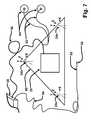
- FIG. 1is a schematic overview of present developments showing a user control box, and a patient drive coil block with drive coil sets, and a guide wire or stylet with a sensor coil and cable.
- FIG. 2is a detailed view of one three-axis drive coil set.
- FIG. 3is a detailed view of a sensor coil.
- FIG. 4is an illustration of magnetic vectors generated by a normal coil drive.
- FIG. 5is an illustration of orthogonal magnetic vectors generated by an x-y virtual drive.
- FIG. 6is an illustration of orthogonal magnetic vectors generated by a y-z virtual drive.
- FIG. 7is a detailed view of a drive coil and sensor coil block with an addition of an optional ECG measurement.
- FIG. 8is a block diagram of a present development hereof.
- FIG. 9is a block diagram of a display/interface and user control box.
- FIG. 10is a block diagram of a function of a main interface board in a user control box.
- FIG. 11is a block diagram of an overall function of a patient drive coil block.
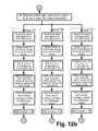
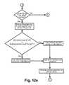
- FIG. 12 a - 12 fdetail algorithms for controlling an acquisition of sensor coil position optionally including display and/or ECG.
- FIG. 13is a detailed block diagram of a function of a coil drive with virtual x-y capability.
- FIG. 14is a detailed block diagram of sensor coil signal processing.
- FIG. 15is a detailed block diagram of a function of a coil drive with full virtual x-y-z capability.
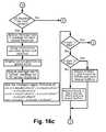
- FIG. 16 a - 16 cdetail some algorithm alternatives for controlling the acquisition and display of sensor coil position in virtual x-y-z system.
- FIG. 1provides an overview of an implementation of a medical device location system hereof.
- a user control box 20may be included, and according to this implementation, contains a touch screen display 22 , a single-board computer (SBC) (not separately shown in FIG. 1 ) for control and data processing, and a main interface board (also not separately shown in FIG. 1 ) which connects to a drive block cable 26 and a medical device cable 32 (also sometimes referred to as a catheter, or guide wire or stylet cable 32 ).
- SBCsingle-board computer
- main interface boardalso not separately shown in FIG. 1
- a triangular patient drive coil block 36may be connected via drive block cable 26 to the control box 20 (the drive coil block also sometimes being referred to as an emitter block, a patient block or merely a drive block).
- Coil drive electronics 28 and three drive coil sets 24 a , 24 b , 24 care mounted in the drive block 36 .
- the coil drive electronics 28allow the SBC to selectively energize any drive coil axis 38 , 40 , 42 of a set 24 (see FIG. 2 ) or group of drive coil axes.
- a sensor coil 30is, in this implementation, built on or within the tip of a medical device such as a small diameter biocompatible guide wire or stylet cable 32 .
- the guide wiremay then be placed in the patient and the catheter then threaded over this wire; or, alternatively, the stylet cable may then be inserted up to the distal end of a catheter before the catheter is placed in the patient.
- a two-conductor cable 34can be used to connect the sensor coil of guide wire or stylet back to the user control box.
- FIG. 2shows a detailed drawing of a drive coil set 24 (representative of any of sets 24 a , 24 b , 24 c ).
- the x-coil 42 , the y-coil 38 and z-coil 40each have a ferrite or ferrous core 44 to enhance the magnetic field generation.
- This figureis only schematically representative of the construction of a drive coil; in actuality, each drive coil may have many windings (e.g. 100 turns) on the ferrite core and can be constructed as three (3) coil pairs to facilitate the intersection of the x, y, and z axes.
- Each coilhere has a set of lead wires 46 to connect back to the multiplexers of the coil drive electronics 28 .
- FIG. 3shows a detailed view of an exemplar medical device; e.g., a guide wire or stylet sensor coil.
- the sensor coil 30can be any suitable gauge (e.g., but not limited to, a very fine gauge (e.g. 0.001′′ diameter)) insulated wire wound around a ferrous core wire 48 .
- This figureis schematically illustrative only of the sensor coil; here, the sensor coil is approximately 400 turns in single layer, but can be any suitable turns per length, e.g., 50-1000, or any range or value therein, e.g., 100, 200, 300, 350, 400, 450, 500, 550, 600, 650, 700, and the like.
- An alternative constructioncan optionally be 400 or more turns in 2, 3, 4, 5, or more layers; here, the advantage of multiple even layers may be the lead wires come off the same end of the coil.
- the sensor coil lead wires 50connect back through a cable to the patient isolated portion of the main interface board.
- a thin insulating tubing 49can be used to provide a protective sleeve for the whole assembly.
- the tip of the ferrous, conductive core wire 48can be polished smooth and can provide an electrical signal as an ECG lead from within the catheter.
- the guide wire or stylet sensor connectionis accomplished with three wires, two (2) for the coil sensor and one (1) for the ECG, through a cable 54 to the patient isolated portion of the main interface board in the user control box 20 .
- the patient drive coil block 60can have two ECG pads added which connect through a cable 62 to the patient isolated portion of the main interface board. These two ECG inputs together with the one ECG from the catheter provide a three-lead ECG measurement system (e.g., see FIG. 10 ).
- FIGS. 4 , 5 and 6illustrate an optional version of the operation of a normal-drive and virtual-drive drive coil set.
- FIG. 4shows magnetic vectors x, y, and z generated by normal coil driving of the x-axis coil 42 , the y-axis coil 38 and z-axis coil 40 (as shown in FIG. 2 ).
- FIG. 5shows the virtual magnetic vector x-y generated by simultaneously driving the x-axis coil 42 and the y-axis coil 38 (as shown in FIG. 2 ) and when both are driven at the same power, the vector is forty-five degrees between the x and y axes.
- the virtual magnetic vector x-( ⁇ y)generated by simultaneously driving the x-axis coil 42 and the phase-inverted, y-axis coil 38 (as shown in FIG. 2 ) and when both are driven at the same power, the vector is minus forty-five degrees between the x and ⁇ y axes. If a digital to analog converter (DAC) is added to control power to the x-axis drive and another DAC added to control power of y-axis drive, then it is possible to point the virtual axis to any angle from 0 to 360 degrees between x and y.
- DACdigital to analog converter
- FIG. 6shows a virtual magnetic vector y-z generated by simultaneously driving the z-axis coil 42 and the y-axis coil 38 (as shown in FIG. 2 ); and a virtual magnetic vector z-( ⁇ y) generated by simultaneously driving the z-axis coil 42 and a phase-inverted, y-axis coil 38 (as shown in FIG. 2 ).
- FIG. 13illustrates the simplest and one optional form of virtual drive (e.g., see FIG. 13 ), it is possible to point a virtual magnet vector to any polar coordinate by simultaneously driving x, y, and z coils at independent power levels (e.g., see FIG. 15 ).
- FIG. 7provides a schematic diagram of an optional medical device location system with optional electrocardiograph (ECG) measurement. This is similar to the FIG. 1 implementation with the addition of three ECG leads.
- the user control box 20connects through a main interface board to the drive block cable 56 and guide wire or stylet cable 54 .
- the patient drive block 60may be connected via drive block cable 56 which includes two isolated ECG lead signals to the control box 20 .
- the coil drive electronics 28 and three x-y-z drive coils 24 a , 24 b , 24 cmay be mounted in the drive block 60 .
- the coil drive electronics 28allow the single board controller (SBC) to selectively energize any drive coil axis 38 , 40 , 42 ( FIG. 2 ) or group of drive coil axes.
- SBCsingle board controller
- ECG pads 64are placed on the patient and connected by ECG lead wires 62 to the drive block 60 .
- the guide wire or stylet sensor 30here is built onto a small diameter biocompatible conductive-tip guide wire or stylet cable 52 which is inserted into a catheter before (stylet) or after (guide wire) the catheter is placed in the patient.
- a three-conductor cable 54connects the guide wire or stylet sensor coil and one ECG lead back to the user control box 20 .
- FIG. 8is an overall schematic diagram of a medical device location system. This figure illustrates connections between a user control box 20 and a sensing guide wire or stylet 30 and a patient drive block 36 , 60 .
- the control box 20can include an integrated, separated, or remote user display and/or interface.
- Each of these componentscan include cables or connectors for one or more of a coil interface, a power supply, a serial interface, a control interface, a status interface, an ECG interface or lead, an oscillator interface, a processor interface, a computer interface, a data interface, a network interface (cable or wireless), an internet interface, a video interface, a touch-screen interface, an SBC control or power interface, a board interface, a sensor interface, an isolator interface, and/or the like as described herein or as known in the art.
- One or more of these cables or connectorscan attach to the patient drive block 36 / 60 or any component thereof.
- FIG. 9is a block diagram of a user control box 20 which in this implementation includes a computer 68 , an LCD display 22 with touch-screen, and a main interface board 70 .
- Each of these componentscan include cables or connectors for one or more of a coil interface, a power supply, a serial interface, a control interface, a status interface, an ECG interface or lead, an oscillator interface, a processor interface, a computer interface, a data interface, a network interface (cable or wireless), an internet interface, a video interface, a touch-screen interface, an computer control or power interface, a board interface, a sensor interface, an isolator interface, and/or the like as described herein or as known in the art.
- FIG. 10provides a detailed block diagram of a main interface board 70 ( FIG. 9 ) and shows a patient isolated section which connects to a guide wire or stylet cable 34 , 54 and an ECG leads from a patient drive block 60 .
- the remainder of the circuitrycontrols power/interface to a patient drive block 36 , 60 and power to a single board computer 68 , including one or more of a voltage regulator, a watchdog switch, a drive switch, a power isolator, a voltage monitor, a cable buffer, a filter, an analog to digital converter, a phase adjuster, a demodulator, a signal filter, a programmable gain amplifier, a coil isolator, a coil sensor coil amplifier, a detector, memory, flash memory, a multiplexor, a polarity inversion switch, and/or the like.
- a voltage regulatorincluding one or more of a voltage regulator, a watchdog switch, a drive switch, a power isolator, a voltage monitor,
- Each of these componentscan include cables or connectors for one or more of a coil interface, a power supply, a serial interface, a control interface, a status interface, an ECG interface or lead, an oscillator interface, a processor interface, a computer interface, a data interface, a network interface (cable or wireless), an internet interface, a video interface, a touch-screen interface, an SBC control or power interface, a board interface, a sensor interface, and/or the like as described herein or as known in the art.
- One or more of these cables or connectorscan attach to a patient drive block 36 / 60 or any component thereof.
- FIG. 11is a detailed block diagram of a patient drive block 36 , 60 ( FIGS. 1 , 7 ).
- a simpler version/option of a patient drive block 36does not have ECG therefore no ECG leads; whereas, patient drive block 60 may include two ECG leads with patient isolation.
- the drive coil drive system in this diagramillustrates a two-coil virtual drive capability allowing the computer software to simultaneously drive two coils at select power levels.
- Such a systemcan include one or more of a voltage regulator, a watchdog switch, a drive switch, a power isolator, a voltage monitor, a cable buffer, a filter, an analog to digital converter, a phase adjuster, a demodulator, a signal filter, a programmable gain amplifier, a coil isolator, a coil sensor coil amplifier, a detector, memory, flash memory, a multiplexor, a polarity inversion switch, and/or the like.
- a voltage regulatora watchdog switch, a drive switch, a power isolator, a voltage monitor, a cable buffer, a filter, an analog to digital converter, a phase adjuster, a demodulator, a signal filter, a programmable gain amplifier, a coil isolator, a coil sensor coil amplifier, a detector, memory, flash memory, a multiplexor, a polarity inversion switch, and/or the like.
- Each of these componentscan include cables or connectors for one or more of a coil interface, a power supply, a serial interface, a control interface, a status interface, an ECG interface or lead, an oscillator interface, a processor interface, a computer interface, a data interface, a network interface (cable or wireless), an internet interface, a video interface, a touchscreen interface, an SBC control or power interface, a board interface, a sensor interface, and/or the like as described herein or as known in the art.
- FIGS. 12 a - fprovide an overview of a software functionality for a medical device location system hereof.
- FIG. 13is a simplified virtual coil drive system located on a patient drive block 36 , 60 .
- a coil driver hereofmay have only two coil drives and only high/low power selection instead of a power control DAC.
- this drive systemit is possible to generate x-y and x-( ⁇ y) virtual coil drive (see FIG. 5 ) and also z-y and z-( ⁇ y) drive (see FIG. 6 ).
- One additional feature of this driveis a low power setting which allows drive power reduction if the sensing coil is too close to the drive coil (see software flow chart FIG. 12 d ).
- driving x-high-power together with y-low-power or driving x-low-power with y-high-poweryields the same virtual axis—forty-five degrees from x and y axes—as driving both at high power.
- FIG. 14is a detailed view of the sensor coil processing system of the main interface board 68 .
- the sensor coil 30 on the guide wire or styletcan be connected through a cable 34 , 54 to the main interface board 68 .
- This sensor coil inputis pre-amplified and filtered then passed through a patient isolation transformer to a software-controlled programmable gain amplifier.
- This amplified signalis then demodulated using the low frequency (e.g. 16 kHz) drive oscillator.
- the softwarethen reads the sensor coil value with a high resolution (e.g. 16 bit or higher resolution) analog to digital converter (ADC). This read value for each drive coil activated and this value is proportional to the magnetic field measured by the sensor coil during that drive coil activation.
- ADCanalog to digital converter
- FIG. 15is a detailed view of a more complex virtual drive system.
- This drive systemallows the x-axis coil 42 , the y-axis coil 38 and z-axis coil 40 to all be driven simultaneously at independent power levels set by computer control through individual digital to analog converters (DAC).
- the virtual magnetic vectoris the vector sum of x-axis drive plus y-axis drive plus z-axis drive.
- This virtual drivepermits the virtual vector to point to any polar coordinate in space, and thus use polar coordinates as an option; however, it may often still be preferable to use a set of three orthogonal “virtual” axes to calculate the sensor coil 30 position.
- FIGS. 16 a - care a software flow chart showing changes drive and sensor coil processing for a fully independent x-y-z virtual drive system (see FIG. 15 ).
- This softwareadds a positive offset test and a negative offset test to the virtual axes for the A-corner coils. If the sensor coil response is stronger for an offset axis ( FIG. 16 c ) than the current virtual axes, the system shifts to use the offset axes.
- An aspect of the present developmentsis to provide an accurate system to generate a three-dimensional indication of location, position, orientation and/or travel of a medical device such as a guide wire or a catheter or stylet placed within a patient.
- a medical devicesuch as a guide wire or a catheter or stylet placed within a patient.
- Thiscan in some implementations include a display of the location and/or travel of the device.
- a system hereofcan include a sensor coil which is disposed in or on the tip of a guide wire or stylet cable, this sensor coil being communicatively cooperative with an external control and/or display box which may also be communicatively connected with an array of three-axis drive coils placed in some implementations in a triangular block on the patient's chest. This is also sometimes referred to as a drive block or an emitter block.
- the blockcontains the coil-drive controller that facilitates driving single coils, or pairs of coils, or triplets of coils together.
- the pair drivingallows x-y, x-z, or y-z coils in a corner to be energized at the same frequency and same power creating a virtual drive axis at a 45 degree angle between the axis pairs.
- the coil-drivemay also have an additional control to invert the drive waveform (shift the phase 180 degrees). This inversion of one coil in the pair can create a virtual drive axis at ⁇ 45 degrees, thus creating an orthogonal pair of virtual axes within a plane.
- the virtual x-y and x-( ⁇ y)are in the same plane as the x and y axes but rotated 45 degrees within the plane.
- This paired drive schemeimproves the measurement accuracy of the system, especially when the sensor inside the catheter tip is substantially or exactly perpendicular to a normal coil drive axis.
- the system controllersequentially drives/energizes each coil, then each pair of coils while measuring the sensor coil response. When the sensor coil is nearly perpendicular to a drive axis there is significantly diminished response; thus, the virtual axis measurement will provide more accurate data for the position algorithm.
- Algorithms within the controllercan be used to select the best data sets—regular x-y-z axis or virtual x-y-z axis—to calculate the sensor/medical device (e.g., catheter tip) location, position and/or orientation.
- a displaycan be used to show the catheter tip location as a position track of x-y location plotted over time plus an indicator for the z-axis, depth of the catheter. Depth could also be indicated by a variety of methods, as for example by thickening the position line segment in the plot as z decreases and thinning the position line segment as z increases. Alternatively, depth can be displayed as a lateral or “depth” view as a position track of y-z location plotted over time.
- a virtual axiscould be created at any angle between a magnet pair in a corner by energizing two magnets at the same frequency but with different current drive (power) levels to yield a vector-sum virtual axis at any angle between 0 and 90 degrees and inverting one coil in this drive scheme to yield a vector-sum virtual axis at any angle between 0 and ⁇ 90 degrees.
- an orthogonal set of axeswould typically still be selected to accurately locate the sensor coil.
- a further extension to this systemcould include energizing all three electromagnetic coils, x-y-z, together in a corner using the programmable current controls and inversion controls. The result here would be a vector sum from x-drive, y-drive, and z-drive coils that creates a virtual drive at any vector within three-dimensional space.
- ECGelectrocardiogram
- An aspect of the present developmentsis an electromagnetic medical device locating system for locating a medical device or the end or the tip thereof in a subject, including one or more of:
- Another aspectmay include: (a) three or more virtual or actual x-y-z axis electromagnetic (EM) triplet drive coils, each including at least three virtual or actual EM drive coils arranged in perpendicular axis to each other along an x-y-z axis, the virtual or actual EM triplet drive coils placed in a two- or three-dimensional geometric array; (b) at least one medical device sensor coil in physical association with at least one medical device tip and connected to at least one demodulator circuit; (c) at least one AC drive controller that (i) drives sequentially one or more of the virtual or actual EM drive coils; and (ii) provides a phase shifted signal to the demodulator; (d) at least one demodulator circuit including at least one demodulator for measuring the sensor coil output signal using frequency correlation with at least one AC coil driver signal from the AC drive controller to provide a synchronously demodulated sensor coil signal; (e) at least one automatic gain control circuit that maximizes the demodulated sensor coil signal; (f) a
- this systemincludes wherein one or more of (i) the virtual or actual EM drive coils or the virtual or actual EM triplet drive coils are arranged outside at least one of a two dimensional plane defined by at least three of the virtual or actual EM triplet drive coils; and/or (ii) at least four of the virtual or actual EM triplet drive coils form a tetrahedron as part of the three-dimensional geometric array.
- the displaydisplays the relative location of the sensor coil or the medical device tip as a tracking of the sensor coil or medical device tip location over time;
- the displaydisplays the sensor tip angle graphically for the user of the system, wherein the medical device tip angle is the angle of maximum response of the sensor coil as measured from sweeping the virtual drive axis through x-y plane (e.g.
- the displaydisplays the sensor tip angle graphically for the user of the system, wherein the medical device tip angle is the angle perpendicular to the angle of minimum response of the sensor coil as measured from sweeping the virtual drive axis through x-y plane (e.g. 0 to 360 degrees) then using this x-y minimum response angle as a vector added to sweep through the virtual z axis.
- An aspect of the present developmentsis to provide a system wherein one or more of the EM drive coils are provided as the virtual EM drive coils, and wherein: (a) one or more controllers that select pairs or triplets of drive current values of the EM drive coils at regular time intervals to provide one or more paired magnetic drive coil vector values at angles from 0 to 90 degrees and phase inversion of at least one of the corresponding EM drive coils in at least one pair of the paired or tripled magnetic drive coil vectors to further provide one or more magnetic drive coil vector values at angles from ⁇ 90 to 0 degrees; (b) one or more controllers that: (i) determine the angle values of maximum and minimum sensor coil responses within a plane using paired coil programmable current drive sweeping a range from 0 to 90 degrees; and (ii) that then determine the angle values of maximum and minimum sensor coil responses within a plane using paired coil programmable current drive sweeping using inverted phases of at least one coil and sweeping a range from ⁇ 90 to 0 degrees; and/
- Such a systemcan be extended wherein the system includes a programmable coil drive current for each of x, y, and z drive coils driven; and wherein (a) the triplets of drive current values selected at regular time intervals are provided as (i) paired magnetic drive coil vector values at angles from 0 to 90 degrees in an x-y plane together with 0 to 90 degrees from the x-y plane to the corresponding z-axis; and (ii) as phase inversion of one or two paired magnetic drive coil vector values at angles from ⁇ 90 to 0 degrees in an x-y plane together with from ⁇ 90 to 0 degrees from the x-y plane to the corresponding z-axis; (b) the angle values of maximum sensor coil responses within a plane for both 0 to 90 and ⁇ 90 to 0 degrees are fixed and used for at least two x and y virtual axes in a virtual plane and the values of maximum sensor coil response are determined for the corresponding virtual z axis to provide at least one maximum virtual x-
- Such a systemcan be enhanced wherein the display further displays P-wave or other cardiac waveform changes over time in combination with the location of the medical device such as a guide wire or stylet tip in relationship to the subject's heart.
- the displayfurther displays P-wave or other cardiac waveform changes over time in combination with the location of the medical device such as a guide wire or stylet tip in relationship to the subject's heart.
- Such a systemcan be extended by further including (i) an x-axis tilt meter and y-axis tilt meter which uses gravity to measure the x-axis and y-axis tilt from true vertical; and (2) a computer to calculate and display the location of the medical device tip as height, width, and depth of the sensor coil corrected for the tilt the geometric array.
- a computerto calculate and display the location of the medical device tip as height, width, and depth of the sensor coil corrected for the tilt the geometric array.
- Such systemcan be extended by further including an electrocardiogram (ECG) operably associated with the geometric array with a display to show the subject's ECG signal over time; or by further including an electroencephalogram (EEG) operably associated with the geometric array with a display to show the subject's EEG signal over time.
- ECGelectrocardiogram
- EEGelectroencephalogram
- An aspect of the present developmentscan include a method for locating a medical device in a subject, including: (a) providing a system as presented herein; (b) inserting and positioning the medical device tip associated with a functional and sterile medical device into the subject; and (c) recording or monitoring the output of the display to locate the medical device tip in the subject.
- Such a methodcan be extended wherein the method further includes the use of at least one selected an electrocardiogram (ECG), an electroencephalogram (EEG), an x-ray machine, an computer assisted tomography (CAT) machine, a positron emission tomography (PET) machine, an endoscope, or an ultrasound imaging device or composition.
- ECGelectrocardiogram
- EEGelectroencephalogram
- CATcomputer assisted tomography
- PETpositron emission tomography
- endoscopeor an ultrasound imaging device or composition.
- An aspect of the present developmentscan include methods, computer systems and software, provided as programming code or instructions on computer readable media or hardware or networks or computer systems, for generating virtual electromagnetic (EM) triplet drive coils for generating data corresponding to the location coordinates for a sensor coil, including:
- the triplets of drive current values selected at regular time intervalsare provided as (i) paired magnetic drive coil vector values at angles from 0 to 90 degrees in an x-y plane added together with coil vectors of the z-axis from 0 to 90 degrees from the x-y plane; and (ii) as phase inversion of one or more paired magnetic drive coil vector values at angles from ⁇ 90 to 0 degrees in an x-y plane added together with coil vectors of the z-axis from ⁇ 90 to 0 degrees from the x-y plane; (b) the angle value of maximum sensor coil response within the x-y plane for both 0 to 90 and ⁇ 90 to 0 degrees is determined as the intermediate virtual maximum x-y axis and this intermediate virtual maximum x-y axis added to the z-axis swept from 0 to 90 and ⁇ 90 to 0 degrees to determine at least one maximum virtual x-y-z vector for at least one of the corresponding EM triplet drive
- FIG. 1is an overview schematic diagram of an implementation of the present developments.
- a control box 20contains a touch screen display 22 with a computer control and data processing.
- the triangular patient drive block 36is connected via power and communications cable 26 to the control box 20 .
- the drive and sensor electronics 28may be located in the block 36 and provide drive coil control and sensor coil demodulation/amplification.
- In the three corners of the block 36are mounted each triplet drive coil set 24 ( 24 a , 24 b , 24 c ).
- each coil set 24could be mounted as feet protruding from the bottom of the block 36 .
- the sensor coil 30is built onto a small diameter biocompatible cable 32 which may be inserted into a medical device such as a catheter to be placed in the patient.
- FIG. 3provides a detailed view of a sensor coil 30 .
- Sensor coil performancecan be improved by winding the coil about a ferromagnetic wire in the tip of the cable 48 .
- the ferromagnetic materialshould be used for the length of the sensor coil 30 and may be followed by non-ferrous material.
- Two fine wires 50 from the sensor coil 30are attached or associated (e.g., glued or wrapped) and sealed 49 down the length of the cable 48 .
- an aspect of this devicemay include continuous display at the position of the sensor coil 30 placed in the tip of a medical device as the medical device moves through the patient's tissue.
- the patient drive block 36 , 60is placed over the patient's body where the medical device will be targeted (e.g., over the chest preferably aligned with the sternal notch if the medical device will be placed in the area of the heart).
- the sensor coil cable 34 , 54 and patient drive block cable 26 , 56are connected to a user control box 20 .
- the user control box 20contains a computer 68 ( FIG. 9 ) which sequentially drives each driver coil 38 , 40 , 42 ( FIG. 2 ) on each axis in every corner 24 a , 24 b , 24 c of the patient drive block 36 , 60 .
- the coil drivercreates magnetic drive vectors as shown in FIG. 4 , 5 , or 6 —where FIG. 4 represents normal drive and FIGS. 5 and 6 represent virtual drive.
- the single board computer 68FIG.
- gain normalizedmeans that if a measured response is value “a” collected at a programmable gain of “4.00” times, then the normalized resultant value is “a” divided by 4.00.
- a non-limiting example of an alternative gain normalizing methodis to multiply each value “a” by 4096/gain, e.g. “a” ⁇ 4096/4.00.
- the programmable gains that can be used as a non-limiting exampleare 1.00, 2.00, 4.00, 8.00, 16.00 and 32.00 plus there can be a final gain stage that is selectable for 1.00 or 1.41 (equivalent to 1/ ⁇ 2).
- Examples of a resultant set of programmable gainsare 1.00, 1.41, 2.00, 2.82, 4.00, 5.64, 8.00, 11.28, 16.00, 22.56 and 32.00.
- the single board computer 68( FIG. 9 ) compares the sum of the squares of the sensor's normal response to the sum of the squares of the sensor's virtual response. Whichever sum is greater or has the stronger response can be used by the computer 68 to calculate the sensor coil 30 location using trilateration which is the calculation of the intersection of three spheres where each sphere is defined as the radial distance of the sensor coil 30 from each x-y-z driver coil set 24 a , 24 b , 24 c ( FIG. 1 ).
- the radial distancecan be defined as a constant divided by the 6 th root of the sum of the squares of the x, y, and z measured normalized response.
- the constant, kis a calibration constant reflecting the strength of each drive coil 38 , 40 , 42 ( FIG. 2 ) and the sensitivity of the sensor coil 30 ( FIG. 1 ).
- a calibration constantcould be generated during manufacturing for each of the drive coils and then stored as calibration constants for each coil in non-volatile memory of the patient drive block.
- dis the distance of each coil from the other
- kis the calibration constant which scales the result into meaningful units of distance, e.g. centimeters or inches.
- the coils on the patient drive plate or block 36 , 60FIGS.
- the coil driver circuitis designed to selectively drive, within a triplet set, pairs of coils, e.g. 38 and 42 ( FIG. 2 ), together at the same frequency and amplitude with an additional driver control to selectively invert the phase of one coil in the pair.
- This paired coil drive of x-y coilscreates the 1st virtual axis at forty-five degrees from the original x and y axes.
- the paired coil driveis then operated with x-( ⁇ y) which drives the x-coil together with inverted-phase y-coil and this creates the 2 nd virtual axis at minus forty-five degrees from the original x and y axes.
- the resultis two orthogonal virtual magnetic vectors as shown by the dashed lines in FIG. 5 for x-y paired coil drive or in FIG. 6 for y-z paired coil drive.
- the single board computer 68FIG. 9
- ( ⁇ y)means inverted phase on y axis drive.
- the measured sensor coil response for paired-coil drivemust be scaled down by 1.4142 because of vector summing of the two coils driven together.
- the coil-driver powercould be scaled down by 0.7071 in hardware when driving pairs so that the vector sum of two coils equals the magnetic vector of a single coil drive.
- the single board computer 68measures the sensor coil response for each corner in normal drive and paired drive, and then selects the strongest signal from each corner comparing the sum of x 2 , y 2 , and z 2 normal coil drive response to the sum of (x-y) 2 , (x-( ⁇ y)) 2 , and z 2 paired coil drive response.
- the strongest signal from each corneris used to calculate the location of the sensor coil 30 using the trilateration method described in the above equations.
- This exampleillustrates paired x-y coil drive; and by logical extension this may also apply to x-z, or y-z paired drive.
- An objective in some implementations of these developmentsmay include improving the accuracy of horizontal (x-y) location; therefore the paired x-y drive can be preferred over x-z or y-z.
- An improvement of the paired-coil drivecan be to add programmable (DAC) power control to the coil drivers on the drive coil drive electronics board 28 ( FIG. 11 ).
- the single board computer 68( FIG. 9 ) has the capability to select pairs of drive current power settings which steer the virtual axis of the paired coils from 0 to 90 degrees. Inversion of one of the coil drivers in the pair provides the capability for virtual axis from ⁇ 90 to 0 degrees.
- the single board computer 68selects pairs of power settings output to the x-y paired coil driver to sweep the virtual drive axis from 0 to 90 degrees while recording the sensor coil response and this process is repeated with the y coil driver phase inverted to sweep from ⁇ 90 to 0 degrees.
- the angle of the virtual axis when the sensor coil response data is maximumindicates the sensor coil 30 ( FIG. 1 ) is parallel to the virtual axis and the angle of the virtual axis when the sensor coil response data is minimum indicates the sensor coil 30 is perpendicular to the virtual axis.
- the maximum angle and minimum angleare orthogonal (perpendicular).
- the single board computer 68calculates the optimum virtual x axis at forty-five degrees from the measured angle for maximum (or minimum) response and calculates the optimum virtual y axis as an angle orthogonal to the virtual x axis.
- the solution for best virtual axes in one cornerapplies to all corners in the patient drive block 36 , 60 ( FIGS. 1 and 7 ).
- the single board computer 68( FIG. 9 ) measures the sensor coil response for all corners using these optimum virtual x axis, optimum virtual y axis plus normal z axis.
- the sum of (virtual x) 2 , (virtual y) 2 , and z 2 sensor coil responses for each corneris used to calculate the position of the sensor coil 30 ( FIG. 1 ) using the trilateration method described in the above equations.
- This exampleillustrates paired x-y coil drive; and by logical extension this also applies to x-z, or y-z paired drive; however, the preference in this development is to improve accuracy of horizontal location and thus use paired x-y drive.
- An alternative, non-limiting, method for finding the optimum virtual x and virtual y axis in the programmable pair-coil drive aboveis to use successive approximation instead of sweeping 0 to 90 degrees.
- the single board computer 68FIG. 9
- the single board computerfirst tests the sensor coil response to the paired coils at virtual axes +45 and ⁇ 45 degrees and selects the virtual axis with the stronger response. Using the stronger axis, the computer then tests the sensor coil response to paired coils at +22.5 and ⁇ 22.5 degrees from the current virtual axis and selects the virtual axis with the stronger response.
- the single board computer 68calculates the optimum virtual x axis at forty-five degrees from the measured angle for maximum response and calculates the optimum virtual y axis as an angle orthogonal to the virtual x axis.
- a selection of the best set of virtual axescan be accomplished with a triplet-coil drive scheme, with programmable power control to the coil drivers for each axis, and with the driver control to selectively invert the phase of any coil in the triplet x-y-z coil sets 24 a , 24 b , 24 c (see FIG. 15 ).
- the single board computer 68FIG. 9
- the single board computer 68has the capability to select pairs of drive current power settings which steer the x-y virtual axis of the paired coils from 0 to 90 degrees. Inversion of one of the coil drivers in the pair provides the capability for x-( ⁇ y) virtual axis from ⁇ 90 to 0 degrees.
- the single board computer 68can sweep the virtual axis 0 to 90 and ⁇ 90 to 0 degrees in z range.
- the microcomputerselects pairs of current settings output to the x-y paired coil driver to sweep the virtual drive axis from 0 to 90 degrees while recording the sensor coil response and this process is repeated with the y coil driver phase inverted to sweep from ⁇ 90 to 0 degrees.
- the angle of the x-y virtual axis when the sensor coil response data is maximumindicates the sensor coil 30 ( FIG. 1 ) is parallel for the x-y plane.
- the single board computer 68sets this x-y axis and sweeps the z axis drive from ⁇ 90 to 0 and 0 to 90 degrees while recording the sensor coil response.
- the polar angle of the x-y-z virtual axis when the sensor coil response data is at maximumindicates the sensor coil 30 is parallel to this virtual x-y-z axis.
- the single board computer 68then repeats this process to find the minimum sensor coil response sweeping x, y, and z axes.
- the polar angle of the x-y-z virtual axis when the sensor coil response data is minimumindicates the sensor coil 30 is perpendicular to this virtual x-y-z axis.
- the single board computer 68calculates a virtual x axis 45 degrees between the maximum and minimum vectors, then calculates the virtual y axis as 90 degrees from the virtual x in the plane defined previously.
- virtual z axisis defined as orthogonal to the plane of virtual minimum and virtual maximum vectors.
- the single board computer 68then tilts the virtual z axis and the plane of virtual x axis and virtual y axis 45 degrees toward the virtual minimum vector, and the result is the optimal virtual axis set which maximizes the sensor coil response.
- the solution for best virtual axes in one cornerapplies to all corners in the driver array.
- the single board computer 68measures the sensor coil response for all corners using these optimum virtual x, y, and z axes.
- the sum of (virtual x) 2 , (virtual y) 2 , and (virtual z) 2 sensor coil responses for each cornermay be used to calculate the sensor coil 30 using the trilateration method described in the above equations.
- One method to maintain the optimum x-y-z axis over timeis to continuously test the sensor coil response to small deviations (offset angle) from the optimum axis (see FIG. 16 c ).
- the single board computer 68compares the sum of (virtual x) 2 , (virtual y) 2 , and (virtual z) 2 sensor coil responses for the current virtual axis to the sum for virtual axis plus offset angle and the sum for virtual axis minus offset angle. The computer 68 then selects the axis with the largest summed response—this becomes the new optimum x-y-z axis and the process continues to iterate testing small deviations over time.
- the single board computer 68may then graphically display the sensor coil position on the display 22 of the control box 20 .
- the positionis continuously updated adding onto the previous graphical data to create a track or path of the sensor coil 30 over time.
- the user interface of the single board computer 68allows the user to clear the recorded track or to save the recorded track to non-volatile memory. Touchscreens have been described; however keyboard or other data input, or user interface options may be used.
- control box 20may provide for a tethered device with the display/control separate from the patient block 36 , 60 ( FIGS. 1 and 7 ).
- an alternative constructionwould be to build a device or system in which the patient block 36 , 60 is battery-powered and connected wirelessly to the control box 20 .
- the control box 20could be integrated into or as part of the patient block and placed on the patient chest or other locations to track medical device position. Wireless and/or wired connections are thus optionally available for the connections of the drive coil sets to the control or system components for the driving thereof; as well as for the connections of the sensor coil to the control or system components for measuring or receiving the response signals of the sensor coil.
- An alternative constructionwould be to use four or more drive coils 24 oriented as a square, rectangle, pentagon, circle, oval, geometric, or any other suitable shape, in or as the patient drive block 36 , 60 ( FIGS. 1 , 7 ).
- FIG. 7An alternative construction is to optionally incorporate electrocardiograph (ECG) monitoring into the medical device location system to facilitate placement of the medical device with sensor coil 30 in close proximity to the heart.
- ECGelectrocardiograph
- the patient drive block 60may be modified with one or more ECG pads 64 and ECG lead wires 62 which attach to the patient's chest and the third ECG lead is provided by a conductive wire 52 added in or otherwise made part of the core of the guide wire or stylet sensor coil 30 .
- An ECG amplifiercan be added to the main interface board 70 ( FIG. 9 ), and the single board computer 68 may then present the ECG on the display 22 as the medical device such as a catheter is advanced within the patient's or subject's body.
- the usercan observe changes in the P-wave or other wave elements of the ECG as the medical device/catheter reaches the heart.
- the single board computer 68could use a waveform analysis to assist the user in recognizing changes occurring to the P-wave or other waveforms.
- a component to this designmay include connecting the signals from the sensor coil 30 and ECG 52 to the user control box 20 . This is complicated in practice by covering the entire patient and patient block 60 with sterile drapes for insertion of the patient's medical device/catheter. In this design, a miniature stereo phone plug or similar could be used to pierce a plastic bag and connect to cable 34 , 54 a pigtail from the user control box 20 .
- Methods, devices and systemscan thus be provided for one or both of two- or three-dimensional location of the disposition of a sensor coil in a subject including: an array of electromagnetic drive coil sets, each set having two or three dimensionally oriented drive coils; a sensor coil being electromagnetically communicative with the array of electromagnetic drive coil sets; and, a system controller communicative with and adapted to energize one or more of the electromagnetic coils in the array of electromagnetic drive coil sets, the energizing of the one or more of the electromagnetic coils including one or more of energizing the coils singly, or in pairs of x-y and y-z or x-z coils while measuring the response of the sensor coil; whereby the system uses the measurements of the responses of the sensor coil to calculate the location and orientation of the sensor coil relative to said drive coil sets.
- Thismay include two- and/or three-dimensional location of a catheter in tissue using an array of x-y or x-y-z oriented electromagnetic coils, where a sensor coil can be associated with one or more catheter tips, and where the system controller can energize one or more external coils, such as but not limited to, pairs of x-y and y-z or x-z coils while measuring the response of the sensor coil; the system can use these sensor coil measurements to calculate the position and orientation of the catheter tip, and in some implementations, the system controller can graphically display the catheter tip position, depth and/or orientation, e.g., but not limited to, over time.
Landscapes
- Health & Medical Sciences (AREA)
- Life Sciences & Earth Sciences (AREA)
- Engineering & Computer Science (AREA)
- Heart & Thoracic Surgery (AREA)
- Molecular Biology (AREA)
- Biophysics (AREA)
- Pathology (AREA)
- Biomedical Technology (AREA)
- Human Computer Interaction (AREA)
- Medical Informatics (AREA)
- Physics & Mathematics (AREA)
- Surgery (AREA)
- Animal Behavior & Ethology (AREA)
- General Health & Medical Sciences (AREA)
- Public Health (AREA)
- Veterinary Medicine (AREA)
- Media Introduction/Drainage Providing Device (AREA)
Abstract
Description
- three or more triplet drive coil sets, each drive coil set including at least three orthogonally arranged discrete drive coils, each of the discrete drive coils being electromagnetic (EM) coils;
- at least one sensor coil;
- one or more system components that one or both provide drive signals energizing said discrete drive coils and measure resulting sensor coil response signals;
wherein the provision of drive signals includes one or both: - (i) sequentially driving one or pairs of said discrete drive coils within a triplet drive coil set; and
- (ii) selectively providing phase inversion of the drive signal to any one or pairs of said discrete drive coils within a triplet drive coil set;
- a computing component for calculating sensor coil disposition in the subject relative to said triplet drive coil sets from one or more measured resulting sensor coil response signals.
- (a) electronically providing triplets of drive current values generated from at least three EM drive coils of the EM triplet drive coils in detectable proximity to the EM sensor at regular time intervals to provide one or more paired magnetic drive coil vector values generated at angles from 0 to 90 degrees without and from −90 to 0 degrees with phase inversion;
- (b) electronically providing angle values of maximum or minimum EM sensor coil responses generated from the EM triplet drive coils within the x-y plane using paired x-y coils' programmable current drive sweeping a range from 0 to 90 degrees without and from −90 to 0 degrees with phase inversion;
- (c) electronically computing at least one set of optimal virtual drive x and y axes as values corresponding to plus and minus 45 degrees from the maximum or the minimum sensor coil response;
- (d) electronically computing an optimal virtual drive z axis orthogonal to the plane of the optimal virtual drive x and y axes to provide at least one optimal set of virtual EM triplet drive axes for at least one of the EM triplet drive coils.
r=k/6√((x2+y2+z2))
r12=k2/3√((x12+y12+z12))
r22=k2/3√((x2−d)2+y22+z22)
r32=k2/3√(x32+(y3−d)2+z32)
Here d is the distance of each coil from the other and k is the calibration constant which scales the result into meaningful units of distance, e.g. centimeters or inches. In this non-limiting example, the coils on the patient drive plate or block36,60 (
xS=(r12−r22+d2)/2d
yS=(r12−r32+d2)/2d
zS=+/−2√(r12−xS2−yS2)
Here the solution for z (vertical axis) is assumed to be negative as the
Claims (35)
Priority Applications (4)
| Application Number | Priority Date | Filing Date | Title |
|---|---|---|---|
| US12/949,663US8391956B2 (en) | 2010-11-18 | 2010-11-18 | Medical device location systems, devices and methods |
| PCT/US2011/061172WO2012068365A2 (en) | 2010-11-18 | 2011-11-17 | Medical device location systems, devices and methods |
| EP11840907.7AEP2640260B1 (en) | 2010-11-18 | 2011-11-17 | Medical device location system |
| EP16203531.5AEP3165156B1 (en) | 2010-11-18 | 2011-11-17 | Medical device locating system |
Applications Claiming Priority (1)
| Application Number | Priority Date | Filing Date | Title |
|---|---|---|---|
| US12/949,663US8391956B2 (en) | 2010-11-18 | 2010-11-18 | Medical device location systems, devices and methods |
Publications (2)
| Publication Number | Publication Date |
|---|---|
| US20120130228A1 US20120130228A1 (en) | 2012-05-24 |
| US8391956B2true US8391956B2 (en) | 2013-03-05 |
Family
ID=46064986
Family Applications (1)
| Application Number | Title | Priority Date | Filing Date |
|---|---|---|---|
| US12/949,663Active2031-09-03US8391956B2 (en) | 2010-11-18 | 2010-11-18 | Medical device location systems, devices and methods |
Country Status (1)
| Country | Link |
|---|---|
| US (1) | US8391956B2 (en) |
Cited By (60)
| Publication number | Priority date | Publication date | Assignee | Title |
|---|---|---|---|---|
| US20110156700A1 (en)* | 2009-12-31 | 2011-06-30 | Itay Kariv | System and method for assessing interference to a signal caused by a magnetic field |
| US8781555B2 (en) | 2007-11-26 | 2014-07-15 | C. R. Bard, Inc. | System for placement of a catheter including a signal-generating stylet |
| US8784336B2 (en) | 2005-08-24 | 2014-07-22 | C. R. Bard, Inc. | Stylet apparatuses and methods of manufacture |
| US8849382B2 (en) | 2007-11-26 | 2014-09-30 | C. R. Bard, Inc. | Apparatus and display methods relating to intravascular placement of a catheter |
| US8858455B2 (en) | 2006-10-23 | 2014-10-14 | Bard Access Systems, Inc. | Method of locating the tip of a central venous catheter |
| WO2015003024A3 (en)* | 2013-07-01 | 2015-04-09 | Zurich Medical Corporation | Apparatus and method for intravascular measurements |
| US9125578B2 (en) | 2009-06-12 | 2015-09-08 | Bard Access Systems, Inc. | Apparatus and method for catheter navigation and tip location |
| US20150282734A1 (en)* | 2014-04-08 | 2015-10-08 | Timothy Schweikert | Medical device placement system and a method for its use |
| US9265443B2 (en) | 2006-10-23 | 2016-02-23 | Bard Access Systems, Inc. | Method of locating the tip of a central venous catheter |
| US9339206B2 (en) | 2009-06-12 | 2016-05-17 | Bard Access Systems, Inc. | Adaptor for endovascular electrocardiography |
| US9383451B2 (en) | 2013-06-19 | 2016-07-05 | Zoll Medical Corporation | Systems and methods of determining location using a medical device |
| US9415188B2 (en) | 2010-10-29 | 2016-08-16 | C. R. Bard, Inc. | Bioimpedance-assisted placement of a medical device |
| US9445734B2 (en) | 2009-06-12 | 2016-09-20 | Bard Access Systems, Inc. | Devices and methods for endovascular electrography |
| US9456766B2 (en) | 2007-11-26 | 2016-10-04 | C. R. Bard, Inc. | Apparatus for use with needle insertion guidance system |
| US9492097B2 (en) | 2007-11-26 | 2016-11-15 | C. R. Bard, Inc. | Needle length determination and calibration for insertion guidance system |
| US9521961B2 (en) | 2007-11-26 | 2016-12-20 | C. R. Bard, Inc. | Systems and methods for guiding a medical instrument |
| US9532724B2 (en) | 2009-06-12 | 2017-01-03 | Bard Access Systems, Inc. | Apparatus and method for catheter navigation using endovascular energy mapping |
| US9554716B2 (en) | 2007-11-26 | 2017-01-31 | C. R. Bard, Inc. | Insertion guidance system for needles and medical components |
| US9566012B2 (en) | 2014-10-27 | 2017-02-14 | Medtronic, Inc. | Method and apparatus for selection and use of virtual sensing vectors |
| US9636031B2 (en) | 2007-11-26 | 2017-05-02 | C.R. Bard, Inc. | Stylets for use with apparatus for intravascular placement of a catheter |
| US9649048B2 (en) | 2007-11-26 | 2017-05-16 | C. R. Bard, Inc. | Systems and methods for breaching a sterile field for intravascular placement of a catheter |
| US9681823B2 (en) | 2007-11-26 | 2017-06-20 | C. R. Bard, Inc. | Integrated system for intravascular placement of a catheter |
| US9839372B2 (en) | 2014-02-06 | 2017-12-12 | C. R. Bard, Inc. | Systems and methods for guidance and placement of an intravascular device |
| US9901714B2 (en) | 2008-08-22 | 2018-02-27 | C. R. Bard, Inc. | Catheter assembly including ECG sensor and magnetic assemblies |
| US9907513B2 (en) | 2008-10-07 | 2018-03-06 | Bard Access Systems, Inc. | Percutaneous magnetic gastrostomy |
| US10039920B1 (en) | 2017-08-02 | 2018-08-07 | Lungpacer Medical, Inc. | Systems and methods for intravascular catheter positioning and/or nerve stimulation |
| US10046139B2 (en) | 2010-08-20 | 2018-08-14 | C. R. Bard, Inc. | Reconfirmation of ECG-assisted catheter tip placement |
| US10188831B2 (en) | 2013-03-14 | 2019-01-29 | Angiodynamics, Inc. | Systems and methods for catheter tip placement using ECG |
| WO2019094530A2 (en) | 2017-11-08 | 2019-05-16 | Teleflex Medical Incorporated | Wireless medical device navigation systems and methods |
| US10293164B2 (en) | 2017-05-26 | 2019-05-21 | Lungpacer Medical Inc. | Apparatus and methods for assisted breathing by transvascular nerve stimulation |
| US10349890B2 (en) | 2015-06-26 | 2019-07-16 | C. R. Bard, Inc. | Connector interface for ECG-based catheter positioning system |
| US10376169B2 (en) | 2015-03-24 | 2019-08-13 | Zoll Medical Corporation | Systems and methods of determining location using a medical device |
| US10391314B2 (en) | 2014-01-21 | 2019-08-27 | Lungpacer Medical Inc. | Systems and related methods for optimization of multi-electrode nerve pacing |
| US10406367B2 (en) | 2012-06-21 | 2019-09-10 | Lungpacer Medical Inc. | Transvascular diaphragm pacing system and methods of use |
| US10449330B2 (en) | 2007-11-26 | 2019-10-22 | C. R. Bard, Inc. | Magnetic element-equipped needle assemblies |
| US10512772B2 (en) | 2012-03-05 | 2019-12-24 | Lungpacer Medical Inc. | Transvascular nerve stimulation apparatus and methods |
| US10524691B2 (en) | 2007-11-26 | 2020-01-07 | C. R. Bard, Inc. | Needle assembly including an aligned magnetic element |
| US10561843B2 (en) | 2007-01-29 | 2020-02-18 | Lungpacer Medical, Inc. | Transvascular nerve stimulation apparatus and methods |
| US10751509B2 (en) | 2007-11-26 | 2020-08-25 | C. R. Bard, Inc. | Iconic representations for guidance of an indwelling medical device |
| US10765483B2 (en) | 2017-04-20 | 2020-09-08 | Medtronic Navigation, Inc. | Navigation system and method |
| US10835183B2 (en) | 2013-07-01 | 2020-11-17 | Zurich Medical Corporation | Apparatus and method for intravascular measurements |
| US10940308B2 (en) | 2017-08-04 | 2021-03-09 | Lungpacer Medical Inc. | Systems and methods for trans-esophageal sympathetic ganglion recruitment |
| US10973584B2 (en) | 2015-01-19 | 2021-04-13 | Bard Access Systems, Inc. | Device and method for vascular access |
| US10992079B2 (en) | 2018-10-16 | 2021-04-27 | Bard Access Systems, Inc. | Safety-equipped connection systems and methods thereof for establishing electrical connections |
| US10987511B2 (en) | 2018-11-08 | 2021-04-27 | Lungpacer Medical Inc. | Stimulation systems and related user interfaces |
| US11000207B2 (en) | 2016-01-29 | 2021-05-11 | C. R. Bard, Inc. | Multiple coil system for tracking a medical device |
| US11273283B2 (en) | 2017-12-31 | 2022-03-15 | Neuroenhancement Lab, LLC | Method and apparatus for neuroenhancement to enhance emotional response |
| US11357979B2 (en) | 2019-05-16 | 2022-06-14 | Lungpacer Medical Inc. | Systems and methods for sensing and stimulation |
| US11364361B2 (en) | 2018-04-20 | 2022-06-21 | Neuroenhancement Lab, LLC | System and method for inducing sleep by transplanting mental states |
| US11452839B2 (en) | 2018-09-14 | 2022-09-27 | Neuroenhancement Lab, LLC | System and method of improving sleep |
| US11707619B2 (en) | 2013-11-22 | 2023-07-25 | Lungpacer Medical Inc. | Apparatus and methods for assisted breathing by transvascular nerve stimulation |
| US11717686B2 (en) | 2017-12-04 | 2023-08-08 | Neuroenhancement Lab, LLC | Method and apparatus for neuroenhancement to facilitate learning and performance |
| US11723579B2 (en) | 2017-09-19 | 2023-08-15 | Neuroenhancement Lab, LLC | Method and apparatus for neuroenhancement |
| US11771900B2 (en) | 2019-06-12 | 2023-10-03 | Lungpacer Medical Inc. | Circuitry for medical stimulation systems |
| US11786694B2 (en) | 2019-05-24 | 2023-10-17 | NeuroLight, Inc. | Device, method, and app for facilitating sleep |
| US11883658B2 (en) | 2017-06-30 | 2024-01-30 | Lungpacer Medical Inc. | Devices and methods for prevention, moderation, and/or treatment of cognitive injury |
| US11918765B2 (en) | 2020-10-01 | 2024-03-05 | Teleflex Medical Incorporated | Stylet with improved threadability |
| US12029903B2 (en) | 2017-12-11 | 2024-07-09 | Lungpacer Medical Inc. | Systems and methods for strengthening a respiratory muscle |
| US12280219B2 (en) | 2017-12-31 | 2025-04-22 | NeuroLight, Inc. | Method and apparatus for neuroenhancement to enhance emotional response |
| US12440238B2 (en) | 2021-09-09 | 2025-10-14 | C. R. Bard, Inc. | Apparatus for use with needle insertion guidance system |
Families Citing this family (10)
| Publication number | Priority date | Publication date | Assignee | Title |
|---|---|---|---|---|
| US8994366B2 (en) | 2012-12-12 | 2015-03-31 | Ascension Technology Corporation | Magnetically tracked sensor |
| US10966629B2 (en)* | 2014-12-01 | 2021-04-06 | Koninklijke Philips N.V. | Virtually-oriented electromagnetic tracking coil for catheter based navigation |
| WO2016134282A1 (en)* | 2015-02-20 | 2016-08-25 | Nostix, Llc | Medical device position location systems, devices and methods |
| US10098567B2 (en)* | 2015-04-29 | 2018-10-16 | Teleflex Medical Devices S.À R.L | Medical device position location systems, devices and methods |
| US10197518B2 (en)* | 2015-02-20 | 2019-02-05 | Teleflex Medical Devices S.À R.L. | Medical device position location systems, devices and methods |
| US11022421B2 (en) | 2016-01-20 | 2021-06-01 | Lucent Medical Systems, Inc. | Low-frequency electromagnetic tracking |
| US11027096B2 (en) | 2017-08-21 | 2021-06-08 | Lucent Medical Systems, Inc. | Flexible circuit bearing a trackable low-frequency electromagnetic coil |
| US11234769B2 (en) | 2018-03-02 | 2022-02-01 | Lucent Medical Systems, Inc. | Wireless electromagnetic navigational element |
| US11426133B2 (en) | 2018-03-13 | 2022-08-30 | Lucent Medical Systems, Inc. | Externally placed electromagnetic fiducial element |
| WO2021222425A1 (en)* | 2020-04-29 | 2021-11-04 | Edwards Lifesciences Corporation | System for detecting catheter looping or knotting |
Citations (18)
| Publication number | Priority date | Publication date | Assignee | Title |
|---|---|---|---|---|
| US4173228A (en) | 1977-05-16 | 1979-11-06 | Applied Medical Devices | Catheter locating device |
| US4560930A (en) | 1982-06-27 | 1985-12-24 | Kono Tsutomu | Distance-measuring system using orthogonal magnetic field generators and orthogonal magnetic field sensors |
| US5005592A (en) | 1989-10-27 | 1991-04-09 | Becton Dickinson And Company | Method and apparatus for tracking catheters |
| US5099845A (en) | 1989-05-24 | 1992-03-31 | Micronix Pty Ltd. | Medical instrument location means |
| US5307072A (en) | 1992-07-09 | 1994-04-26 | Polhemus Incorporated | Non-concentricity compensation in position and orientation measurement systems |
| US5429132A (en) | 1990-08-24 | 1995-07-04 | Imperial College Of Science Technology And Medicine | Probe system |
| US5558091A (en) | 1993-10-06 | 1996-09-24 | Biosense, Inc. | Magnetic determination of position and orientation |
| US5645065A (en) | 1991-09-04 | 1997-07-08 | Navion Biomedical Corporation | Catheter depth, position and orientation location system |
| US5729129A (en) | 1995-06-07 | 1998-03-17 | Biosense, Inc. | Magnetic location system with feedback adjustment of magnetic field generator |
| US5879297A (en) | 1997-05-08 | 1999-03-09 | Lucent Medical Systems, Inc. | System and method to determine the location and orientation of an indwelling medical device |
| US5913820A (en) | 1992-08-14 | 1999-06-22 | British Telecommunications Public Limited Company | Position location system |
| US6487516B1 (en) | 1998-10-29 | 2002-11-26 | Netmor Ltd. | System for three dimensional positioning and tracking with dynamic range extension |
| US6615155B2 (en) | 2000-03-09 | 2003-09-02 | Super Dimension Ltd. | Object tracking using a single sensor or a pair of sensors |
| US6690963B2 (en) | 1995-01-24 | 2004-02-10 | Biosense, Inc. | System for determining the location and orientation of an invasive medical instrument |
| US6701179B1 (en) | 1999-10-28 | 2004-03-02 | Michael A. Martinelli | Coil structures and methods for generating magnetic fields |
| US6757557B1 (en) | 1992-08-14 | 2004-06-29 | British Telecommunications | Position location system |
| US6774624B2 (en) | 2002-03-27 | 2004-08-10 | Ge Medical Systems Global Technology Company, Llc | Magnetic tracking system |
| US7366562B2 (en) | 2003-10-17 | 2008-04-29 | Medtronic Navigation, Inc. | Method and apparatus for surgical navigation |
- 2010
- 2010-11-18USUS12/949,663patent/US8391956B2/enactiveActive
Patent Citations (21)
| Publication number | Priority date | Publication date | Assignee | Title |
|---|---|---|---|---|
| US4173228A (en) | 1977-05-16 | 1979-11-06 | Applied Medical Devices | Catheter locating device |
| US4560930A (en) | 1982-06-27 | 1985-12-24 | Kono Tsutomu | Distance-measuring system using orthogonal magnetic field generators and orthogonal magnetic field sensors |
| US5099845A (en) | 1989-05-24 | 1992-03-31 | Micronix Pty Ltd. | Medical instrument location means |
| US5005592A (en) | 1989-10-27 | 1991-04-09 | Becton Dickinson And Company | Method and apparatus for tracking catheters |
| US5429132A (en) | 1990-08-24 | 1995-07-04 | Imperial College Of Science Technology And Medicine | Probe system |
| US5645065A (en) | 1991-09-04 | 1997-07-08 | Navion Biomedical Corporation | Catheter depth, position and orientation location system |
| US5307072A (en) | 1992-07-09 | 1994-04-26 | Polhemus Incorporated | Non-concentricity compensation in position and orientation measurement systems |
| US5913820A (en) | 1992-08-14 | 1999-06-22 | British Telecommunications Public Limited Company | Position location system |
| US6757557B1 (en) | 1992-08-14 | 2004-06-29 | British Telecommunications | Position location system |
| US6516212B1 (en) | 1992-08-14 | 2003-02-04 | British Telecommunications Public Limited Company | Three dimensional mapping |
| US6522907B1 (en) | 1992-08-14 | 2003-02-18 | British Telecommunications Public Limited Company | Surgical navigation |
| US7174202B2 (en) | 1992-08-14 | 2007-02-06 | British Telecommunications | Medical navigation apparatus |
| US5558091A (en) | 1993-10-06 | 1996-09-24 | Biosense, Inc. | Magnetic determination of position and orientation |
| US6690963B2 (en) | 1995-01-24 | 2004-02-10 | Biosense, Inc. | System for determining the location and orientation of an invasive medical instrument |
| US5729129A (en) | 1995-06-07 | 1998-03-17 | Biosense, Inc. | Magnetic location system with feedback adjustment of magnetic field generator |
| US5879297A (en) | 1997-05-08 | 1999-03-09 | Lucent Medical Systems, Inc. | System and method to determine the location and orientation of an indwelling medical device |
| US6487516B1 (en) | 1998-10-29 | 2002-11-26 | Netmor Ltd. | System for three dimensional positioning and tracking with dynamic range extension |
| US6701179B1 (en) | 1999-10-28 | 2004-03-02 | Michael A. Martinelli | Coil structures and methods for generating magnetic fields |
| US6615155B2 (en) | 2000-03-09 | 2003-09-02 | Super Dimension Ltd. | Object tracking using a single sensor or a pair of sensors |
| US6774624B2 (en) | 2002-03-27 | 2004-08-10 | Ge Medical Systems Global Technology Company, Llc | Magnetic tracking system |
| US7366562B2 (en) | 2003-10-17 | 2008-04-29 | Medtronic Navigation, Inc. | Method and apparatus for surgical navigation |
Non-Patent Citations (2)
| Title |
|---|
| Schneider, M., "Electromagnetic Tracking for Catheter Localization," Part of the SPIE Conference on Biomedical Diagnostic, Guidance, and Surgical-Assist Systems; San Jose, California; SPIE; vol. 3595; pp. 61-68; Jan. 1999. |
| Solomon, S. et al., "TIPS placement in swine, guided by electromagnetic real-time needle tip localization displayed on previously acquired 3-D CT," Cardiovascular and Interventional Radiology; vol. 22, No. 5; pp. 411-414; Sep. 1999. |
Cited By (130)
| Publication number | Priority date | Publication date | Assignee | Title |
|---|---|---|---|---|
| US10004875B2 (en) | 2005-08-24 | 2018-06-26 | C. R. Bard, Inc. | Stylet apparatuses and methods of manufacture |
| US8784336B2 (en) | 2005-08-24 | 2014-07-22 | C. R. Bard, Inc. | Stylet apparatuses and methods of manufacture |
| US11207496B2 (en) | 2005-08-24 | 2021-12-28 | C. R. Bard, Inc. | Stylet apparatuses and methods of manufacture |
| US9265443B2 (en) | 2006-10-23 | 2016-02-23 | Bard Access Systems, Inc. | Method of locating the tip of a central venous catheter |
| US9833169B2 (en) | 2006-10-23 | 2017-12-05 | Bard Access Systems, Inc. | Method of locating the tip of a central venous catheter |
| US9345422B2 (en) | 2006-10-23 | 2016-05-24 | Bard Acess Systems, Inc. | Method of locating the tip of a central venous catheter |
| US8858455B2 (en) | 2006-10-23 | 2014-10-14 | Bard Access Systems, Inc. | Method of locating the tip of a central venous catheter |
| US10864374B2 (en) | 2007-01-29 | 2020-12-15 | Lungpacer Medical Inc. | Transvascular nerve stimulation apparatus and methods |
| US11027130B2 (en) | 2007-01-29 | 2021-06-08 | Lungpacer Medical Inc. | Transvascular nerve stimulation apparatus and methods |
| US10561843B2 (en) | 2007-01-29 | 2020-02-18 | Lungpacer Medical, Inc. | Transvascular nerve stimulation apparatus and methods |
| US10765867B2 (en) | 2007-01-29 | 2020-09-08 | Lungpacer Medical Inc. | Transvascular nerve stimulation apparatus and methods |
| US12268877B2 (en) | 2007-01-29 | 2025-04-08 | Lungpacer Medical Inc. | Transvascular nerve stimulation apparatus and methods |
| US10792499B2 (en) | 2007-01-29 | 2020-10-06 | Lungpacer Medical Inc. | Transvascular nerve stimulation apparatus and methods |
| US10966630B2 (en) | 2007-11-26 | 2021-04-06 | C. R. Bard, Inc. | Integrated system for intravascular placement of a catheter |
| US9649048B2 (en) | 2007-11-26 | 2017-05-16 | C. R. Bard, Inc. | Systems and methods for breaching a sterile field for intravascular placement of a catheter |
| US10231753B2 (en) | 2007-11-26 | 2019-03-19 | C. R. Bard, Inc. | Insertion guidance system for needles and medical components |
| US8849382B2 (en) | 2007-11-26 | 2014-09-30 | C. R. Bard, Inc. | Apparatus and display methods relating to intravascular placement of a catheter |
| US11707205B2 (en) | 2007-11-26 | 2023-07-25 | C. R. Bard, Inc. | Integrated system for intravascular placement of a catheter |
| US9456766B2 (en) | 2007-11-26 | 2016-10-04 | C. R. Bard, Inc. | Apparatus for use with needle insertion guidance system |
| US9492097B2 (en) | 2007-11-26 | 2016-11-15 | C. R. Bard, Inc. | Needle length determination and calibration for insertion guidance system |
| US9521961B2 (en) | 2007-11-26 | 2016-12-20 | C. R. Bard, Inc. | Systems and methods for guiding a medical instrument |
| US9526440B2 (en) | 2007-11-26 | 2016-12-27 | C.R. Bard, Inc. | System for placement of a catheter including a signal-generating stylet |
| US10238418B2 (en) | 2007-11-26 | 2019-03-26 | C. R. Bard, Inc. | Apparatus for use with needle insertion guidance system |
| US10849695B2 (en) | 2007-11-26 | 2020-12-01 | C. R. Bard, Inc. | Systems and methods for breaching a sterile field for intravascular placement of a catheter |
| US9549685B2 (en) | 2007-11-26 | 2017-01-24 | C. R. Bard, Inc. | Apparatus and display methods relating to intravascular placement of a catheter |
| US9554716B2 (en) | 2007-11-26 | 2017-01-31 | C. R. Bard, Inc. | Insertion guidance system for needles and medical components |
| US11134915B2 (en) | 2007-11-26 | 2021-10-05 | C. R. Bard, Inc. | System for placement of a catheter including a signal-generating stylet |
| US9636031B2 (en) | 2007-11-26 | 2017-05-02 | C.R. Bard, Inc. | Stylets for use with apparatus for intravascular placement of a catheter |
| US11123099B2 (en) | 2007-11-26 | 2021-09-21 | C. R. Bard, Inc. | Apparatus for use with needle insertion guidance system |
| US9681823B2 (en) | 2007-11-26 | 2017-06-20 | C. R. Bard, Inc. | Integrated system for intravascular placement of a catheter |
| US8781555B2 (en) | 2007-11-26 | 2014-07-15 | C. R. Bard, Inc. | System for placement of a catheter including a signal-generating stylet |
| US11779240B2 (en) | 2007-11-26 | 2023-10-10 | C. R. Bard, Inc. | Systems and methods for breaching a sterile field for intravascular placement of a catheter |
| US10342575B2 (en) | 2007-11-26 | 2019-07-09 | C. R. Bard, Inc. | Apparatus for use with needle insertion guidance system |
| US10751509B2 (en) | 2007-11-26 | 2020-08-25 | C. R. Bard, Inc. | Iconic representations for guidance of an indwelling medical device |
| US9999371B2 (en) | 2007-11-26 | 2018-06-19 | C. R. Bard, Inc. | Integrated system for intravascular placement of a catheter |
| US12295714B2 (en) | 2007-11-26 | 2025-05-13 | C. R. Bard, Inc. | Needle assembly including an aligned magnetic element |
| US10602958B2 (en) | 2007-11-26 | 2020-03-31 | C. R. Bard, Inc. | Systems and methods for guiding a medical instrument |
| US11529070B2 (en) | 2007-11-26 | 2022-12-20 | C. R. Bard, Inc. | System and methods for guiding a medical instrument |
| US10105121B2 (en) | 2007-11-26 | 2018-10-23 | C. R. Bard, Inc. | System for placement of a catheter including a signal-generating stylet |
| US10165962B2 (en) | 2007-11-26 | 2019-01-01 | C. R. Bard, Inc. | Integrated systems for intravascular placement of a catheter |
| US10524691B2 (en) | 2007-11-26 | 2020-01-07 | C. R. Bard, Inc. | Needle assembly including an aligned magnetic element |
| US10449330B2 (en) | 2007-11-26 | 2019-10-22 | C. R. Bard, Inc. | Magnetic element-equipped needle assemblies |
| US9901714B2 (en) | 2008-08-22 | 2018-02-27 | C. R. Bard, Inc. | Catheter assembly including ECG sensor and magnetic assemblies |
| US11027101B2 (en) | 2008-08-22 | 2021-06-08 | C. R. Bard, Inc. | Catheter assembly including ECG sensor and magnetic assemblies |
| US9907513B2 (en) | 2008-10-07 | 2018-03-06 | Bard Access Systems, Inc. | Percutaneous magnetic gastrostomy |
| US10271762B2 (en) | 2009-06-12 | 2019-04-30 | Bard Access Systems, Inc. | Apparatus and method for catheter navigation using endovascular energy mapping |
| US9339206B2 (en) | 2009-06-12 | 2016-05-17 | Bard Access Systems, Inc. | Adaptor for endovascular electrocardiography |
| US10231643B2 (en) | 2009-06-12 | 2019-03-19 | Bard Access Systems, Inc. | Apparatus and method for catheter navigation and tip location |
| US10349857B2 (en) | 2009-06-12 | 2019-07-16 | Bard Access Systems, Inc. | Devices and methods for endovascular electrography |
| US9125578B2 (en) | 2009-06-12 | 2015-09-08 | Bard Access Systems, Inc. | Apparatus and method for catheter navigation and tip location |
| US9445734B2 (en) | 2009-06-12 | 2016-09-20 | Bard Access Systems, Inc. | Devices and methods for endovascular electrography |
| US11419517B2 (en) | 2009-06-12 | 2022-08-23 | Bard Access Systems, Inc. | Apparatus and method for catheter navigation using endovascular energy mapping |
| US10912488B2 (en) | 2009-06-12 | 2021-02-09 | Bard Access Systems, Inc. | Apparatus and method for catheter navigation and tip location |
| US9532724B2 (en) | 2009-06-12 | 2017-01-03 | Bard Access Systems, Inc. | Apparatus and method for catheter navigation using endovascular energy mapping |
| US8600480B2 (en)* | 2009-12-31 | 2013-12-03 | Mediguide Ltd. | System and method for assessing interference to a signal caused by a magnetic field |
| US20110156700A1 (en)* | 2009-12-31 | 2011-06-30 | Itay Kariv | System and method for assessing interference to a signal caused by a magnetic field |
| US10046139B2 (en) | 2010-08-20 | 2018-08-14 | C. R. Bard, Inc. | Reconfirmation of ECG-assisted catheter tip placement |
| US9415188B2 (en) | 2010-10-29 | 2016-08-16 | C. R. Bard, Inc. | Bioimpedance-assisted placement of a medical device |
| US10512772B2 (en) | 2012-03-05 | 2019-12-24 | Lungpacer Medical Inc. | Transvascular nerve stimulation apparatus and methods |
| US11369787B2 (en) | 2012-03-05 | 2022-06-28 | Lungpacer Medical Inc. | Transvascular nerve stimulation apparatus and methods |
| US10406367B2 (en) | 2012-06-21 | 2019-09-10 | Lungpacer Medical Inc. | Transvascular diaphragm pacing system and methods of use |
| US10589097B2 (en) | 2012-06-21 | 2020-03-17 | Lungpacer Medical Inc. | Transvascular diaphragm pacing systems and methods of use |
| US10561844B2 (en) | 2012-06-21 | 2020-02-18 | Lungpacer Medical Inc. | Diaphragm pacing systems and methods of use |
| US11357985B2 (en) | 2012-06-21 | 2022-06-14 | Lungpacer Medical Inc. | Transvascular diaphragm pacing systems and methods of use |
| US10188831B2 (en) | 2013-03-14 | 2019-01-29 | Angiodynamics, Inc. | Systems and methods for catheter tip placement using ECG |
| US10980444B2 (en) | 2013-06-19 | 2021-04-20 | Zoll Medical Corporation | Systems and methods of determining location using a medical device |
| US11690532B2 (en) | 2013-06-19 | 2023-07-04 | Zoll Medical Corporation | Systems and methods of determining location using a medical device |
| US9383451B2 (en) | 2013-06-19 | 2016-07-05 | Zoll Medical Corporation | Systems and methods of determining location using a medical device |
| US12220228B2 (en) | 2013-06-19 | 2025-02-11 | Zoll Medical Corporation | Systems and methods of determining location using a medical device |
| US10271771B2 (en) | 2013-06-19 | 2019-04-30 | Zoll Medical Corporation | Systems and methods of determining location using a medical device |
| US11471061B2 (en) | 2013-07-01 | 2022-10-18 | Zurich Medical Corporation | Apparatus and method for intravascular measurements |
| KR101697908B1 (en) | 2013-07-01 | 2017-01-18 | 쥬어리크 메디컬 코퍼레이션 | Apparatus and method for intravascular measurements |
| US10835183B2 (en) | 2013-07-01 | 2020-11-17 | Zurich Medical Corporation | Apparatus and method for intravascular measurements |
| WO2015003024A3 (en)* | 2013-07-01 | 2015-04-09 | Zurich Medical Corporation | Apparatus and method for intravascular measurements |
| JP2016529957A (en)* | 2013-07-01 | 2016-09-29 | ズーリック・メディカル・コーポレイションZurich Medical Corporation | Apparatus and method for intravascular measurement |
| KR20160025564A (en)* | 2013-07-01 | 2016-03-08 | 쥬어리크 메디컬 코퍼레이션 | Apparatus and method for intravascular measurements |
| US10702170B2 (en) | 2013-07-01 | 2020-07-07 | Zurich Medical Corporation | Apparatus and method for intravascular measurements |
| US12239838B2 (en) | 2013-11-22 | 2025-03-04 | Lungpacer Medical Inc. | Apparatus and methods for assisted breathing by transvascular nerve stimulation |
| US11707619B2 (en) | 2013-11-22 | 2023-07-25 | Lungpacer Medical Inc. | Apparatus and methods for assisted breathing by transvascular nerve stimulation |
| US10391314B2 (en) | 2014-01-21 | 2019-08-27 | Lungpacer Medical Inc. | Systems and related methods for optimization of multi-electrode nerve pacing |
| US11311730B2 (en) | 2014-01-21 | 2022-04-26 | Lungpacer Medical Inc. | Systems and related methods for optimization of multi-electrode nerve pacing |
| US12172020B2 (en) | 2014-01-21 | 2024-12-24 | Lungpacer Medical Inc. | Systems and related methods for optimization of multi-electrode nerve pacing |
| US10863920B2 (en) | 2014-02-06 | 2020-12-15 | C. R. Bard, Inc. | Systems and methods for guidance and placement of an intravascular device |
| US9839372B2 (en) | 2014-02-06 | 2017-12-12 | C. R. Bard, Inc. | Systems and methods for guidance and placement of an intravascular device |
| US20150282734A1 (en)* | 2014-04-08 | 2015-10-08 | Timothy Schweikert | Medical device placement system and a method for its use |
| WO2015157398A1 (en)* | 2014-04-08 | 2015-10-15 | Medical Components, Inc. | Medical device placement system and a method for its use |
| US11607150B2 (en) | 2014-04-08 | 2023-03-21 | Angiodynamics Va Llc | Medical device placement system and a method for its use |
| US9566012B2 (en) | 2014-10-27 | 2017-02-14 | Medtronic, Inc. | Method and apparatus for selection and use of virtual sensing vectors |
| US10973584B2 (en) | 2015-01-19 | 2021-04-13 | Bard Access Systems, Inc. | Device and method for vascular access |
| US10376169B2 (en) | 2015-03-24 | 2019-08-13 | Zoll Medical Corporation | Systems and methods of determining location using a medical device |
| US11191470B2 (en) | 2015-03-24 | 2021-12-07 | Zoll Medical Corporation | Systems and methods of determining location using a medical device |
| US10349890B2 (en) | 2015-06-26 | 2019-07-16 | C. R. Bard, Inc. | Connector interface for ECG-based catheter positioning system |
| US11026630B2 (en) | 2015-06-26 | 2021-06-08 | C. R. Bard, Inc. | Connector interface for ECG-based catheter positioning system |
| US11000207B2 (en) | 2016-01-29 | 2021-05-11 | C. R. Bard, Inc. | Multiple coil system for tracking a medical device |
| US11564747B2 (en) | 2017-04-20 | 2023-01-31 | Medtronic Navigation, Inc. | Navigation system and method |
| US10765483B2 (en) | 2017-04-20 | 2020-09-08 | Medtronic Navigation, Inc. | Navigation system and method |
| US11660146B2 (en) | 2017-04-20 | 2023-05-30 | Medtronic Navigation, Inc. | Navigation system and method |
| US12268453B2 (en) | 2017-04-20 | 2025-04-08 | Medtronic Navigation, Inc. | Navigation system and method |
| US10293164B2 (en) | 2017-05-26 | 2019-05-21 | Lungpacer Medical Inc. | Apparatus and methods for assisted breathing by transvascular nerve stimulation |
| US11883658B2 (en) | 2017-06-30 | 2024-01-30 | Lungpacer Medical Inc. | Devices and methods for prevention, moderation, and/or treatment of cognitive injury |
| US12029901B2 (en) | 2017-06-30 | 2024-07-09 | Lungpacer Medical Inc. | Devices and methods for prevention, moderation, and/or treatment of cognitive injury |
| US10039920B1 (en) | 2017-08-02 | 2018-08-07 | Lungpacer Medical, Inc. | Systems and methods for intravascular catheter positioning and/or nerve stimulation |
| US10926087B2 (en) | 2017-08-02 | 2021-02-23 | Lungpacer Medical Inc. | Systems and methods for intravascular catheter positioning and/or nerve stimulation |
| US10195429B1 (en) | 2017-08-02 | 2019-02-05 | Lungpacer Medical Inc. | Systems and methods for intravascular catheter positioning and/or nerve stimulation |
| US11944810B2 (en) | 2017-08-04 | 2024-04-02 | Lungpacer Medical Inc. | Systems and methods for trans-esophageal sympathetic ganglion recruitment |
| US10940308B2 (en) | 2017-08-04 | 2021-03-09 | Lungpacer Medical Inc. | Systems and methods for trans-esophageal sympathetic ganglion recruitment |
| US11723579B2 (en) | 2017-09-19 | 2023-08-15 | Neuroenhancement Lab, LLC | Method and apparatus for neuroenhancement |
| US11744647B2 (en) | 2017-11-08 | 2023-09-05 | Teleflex Medical Incorporated | Wireless medical device navigation systems and methods |
| WO2019094530A2 (en) | 2017-11-08 | 2019-05-16 | Teleflex Medical Incorporated | Wireless medical device navigation systems and methods |
| US11717686B2 (en) | 2017-12-04 | 2023-08-08 | Neuroenhancement Lab, LLC | Method and apparatus for neuroenhancement to facilitate learning and performance |
| US12029903B2 (en) | 2017-12-11 | 2024-07-09 | Lungpacer Medical Inc. | Systems and methods for strengthening a respiratory muscle |
| US11273283B2 (en) | 2017-12-31 | 2022-03-15 | Neuroenhancement Lab, LLC | Method and apparatus for neuroenhancement to enhance emotional response |
| US12397128B2 (en) | 2017-12-31 | 2025-08-26 | NeuroLight, Inc. | Method and apparatus for neuroenhancement to enhance emotional response |
| US12280219B2 (en) | 2017-12-31 | 2025-04-22 | NeuroLight, Inc. | Method and apparatus for neuroenhancement to enhance emotional response |
| US12383696B2 (en) | 2017-12-31 | 2025-08-12 | NeuroLight, Inc. | Method and apparatus for neuroenhancement to enhance emotional response |
| US11318277B2 (en) | 2017-12-31 | 2022-05-03 | Neuroenhancement Lab, LLC | Method and apparatus for neuroenhancement to enhance emotional response |
| US11478603B2 (en) | 2017-12-31 | 2022-10-25 | Neuroenhancement Lab, LLC | Method and apparatus for neuroenhancement to enhance emotional response |
| US11364361B2 (en) | 2018-04-20 | 2022-06-21 | Neuroenhancement Lab, LLC | System and method for inducing sleep by transplanting mental states |
| US11452839B2 (en) | 2018-09-14 | 2022-09-27 | Neuroenhancement Lab, LLC | System and method of improving sleep |
| US11621518B2 (en) | 2018-10-16 | 2023-04-04 | Bard Access Systems, Inc. | Safety-equipped connection systems and methods thereof for establishing electrical connections |
| US10992079B2 (en) | 2018-10-16 | 2021-04-27 | Bard Access Systems, Inc. | Safety-equipped connection systems and methods thereof for establishing electrical connections |
| US11717673B2 (en) | 2018-11-08 | 2023-08-08 | Lungpacer Medical Inc. | Stimulation systems and related user interfaces |
| US10987511B2 (en) | 2018-11-08 | 2021-04-27 | Lungpacer Medical Inc. | Stimulation systems and related user interfaces |
| US11890462B2 (en) | 2018-11-08 | 2024-02-06 | Lungpacer Medical Inc. | Stimulation systems and related user interfaces |
| US11357979B2 (en) | 2019-05-16 | 2022-06-14 | Lungpacer Medical Inc. | Systems and methods for sensing and stimulation |
| US11786694B2 (en) | 2019-05-24 | 2023-10-17 | NeuroLight, Inc. | Device, method, and app for facilitating sleep |
| US11771900B2 (en) | 2019-06-12 | 2023-10-03 | Lungpacer Medical Inc. | Circuitry for medical stimulation systems |
| US12403312B2 (en) | 2019-06-12 | 2025-09-02 | Lungpacer Medical Inc. | Circuitry for medical stimulation systems |
| US11918765B2 (en) | 2020-10-01 | 2024-03-05 | Teleflex Medical Incorporated | Stylet with improved threadability |
| US12440238B2 (en) | 2021-09-09 | 2025-10-14 | C. R. Bard, Inc. | Apparatus for use with needle insertion guidance system |
Also Published As
| Publication number | Publication date |
|---|---|
| US20120130228A1 (en) | 2012-05-24 |
Similar Documents
| Publication | Publication Date | Title |
|---|---|---|
| US8391956B2 (en) | Medical device location systems, devices and methods | |
| US8380289B2 (en) | Medical device location systems, devices and methods | |
| US11150207B2 (en) | Medical device position location systems, devices and methods | |
| US11122991B2 (en) | Medical device position location systems, devices and methods | |
| US10480959B2 (en) | Medical device position location systems, devices and methods | |
| EP2640260B1 (en) | Medical device location system | |
| CN101248996B (en) | Coil arrangement for electromagnetic tracking method and system | |
| US7834621B2 (en) | Electromagnetic tracking employing scalar-magnetometer | |
| US10639004B2 (en) | Method and apparatus for localizing an ultrasound catheter | |
| US7902817B2 (en) | Electromagnetic tracking method and system | |
| CN1250161C (en) | Systems and methods for determining position and orientation of inbuilt medical instruments | |
| JP6710747B2 (en) | Position tracking system | |
| US20200085343A1 (en) | Medical device position location systems, devices and/or methods | |
| US20220183584A1 (en) | Medical device position location systems, devices and methods | |
| HK40027994B (en) | Medical device position location systems, devices and methods | |
| HK40027994A (en) | Medical device position location systems, devices and methods | |
| CN109890312A (en) | System and method for identifying the location and/or orientation of an electromagnetic sensor based on a map | |
| US20250040828A1 (en) | Cardiac mapping systems and methods with integrated navigation modes |
Legal Events
| Date | Code | Title | Description |
|---|---|---|---|
| AS | Assignment | Owner name:NOSTIX, COLORADO Free format text:ASSIGNMENT OF ASSIGNORS INTEREST;ASSIGNORS:ZELLERS, ROBERT D.;NELSON, PETER E.;HENRY, CHARLES W.;REEL/FRAME:025786/0834 Effective date:20110210 | |
| STCF | Information on status: patent grant | Free format text:PATENTED CASE | |
| FEPP | Fee payment procedure | Free format text:PAT HOLDER NO LONGER CLAIMS SMALL ENTITY STATUS, ENTITY STATUS SET TO UNDISCOUNTED (ORIGINAL EVENT CODE: STOL); ENTITY STATUS OF PATENT OWNER: LARGE ENTITY | |
| AS | Assignment | Owner name:ARROW INTERNATIONAL, INC., PENNSYLVANIA Free format text:MERGER;ASSIGNOR:NOSTIX, LLC;REEL/FRAME:038700/0020 Effective date:20160204 | |
| AS | Assignment | Owner name:NOSTIX, LLC, COLORADO Free format text:CONFIRMATORY ASSIGNMENT;ASSIGNORS:ZELLERS, ROBERT D.;NELSON, PETER E.;HENRY, CHARLES W.;SIGNING DATES FROM 20160607 TO 20160630;REEL/FRAME:039254/0048 | |
| AS | Assignment | Owner name:TELEFLEX MEDICAL DEVICES S.A R.L, LUXEMBOURG Free format text:ASSIGNMENT OF ASSIGNORS INTEREST;ASSIGNOR:ARROW INTERNATIONAL, INC.;REEL/FRAME:039345/0985 Effective date:20160711 | |
| FPAY | Fee payment | Year of fee payment:4 | |
| AS | Assignment | Owner name:TELEFLEX LIFE SCIENCES LIMITED, MALTA Free format text:ASSIGNMENT OF ASSIGNORS INTEREST;ASSIGNOR:TELEFLEX MEDICAL DEVICES S.A R.L.;REEL/FRAME:051580/0212 Effective date:20191230 | |
| MAFP | Maintenance fee payment | Free format text:PAYMENT OF MAINTENANCE FEE, 8TH YEAR, LARGE ENTITY (ORIGINAL EVENT CODE: M1552); ENTITY STATUS OF PATENT OWNER: LARGE ENTITY Year of fee payment:8 | |
| AS | Assignment | Owner name:ARROW INTERNATIONAL LLC, NORTH CAROLINA Free format text:CONVERSION AND CHANGE OF NAME;ASSIGNOR:ARROW INTERNATIONAL, INC.;REEL/FRAME:053754/0731 Effective date:20200330 | |
| AS | Assignment | Owner name:TELEFLEX LIFE SCIENCES III LLC, DELAWARE Free format text:ASSIGNMENT OF ASSIGNORS INTEREST;ASSIGNOR:TELEFLEX LIFE SCIENCES LIMITED;REEL/FRAME:066617/0582 Effective date:20231211 Owner name:TELEFLEX LIFE SCIENCES LLC, DELAWARE Free format text:MERGER;ASSIGNOR:TELEFLEX LIFE SCIENCES III LLC;REEL/FRAME:066621/0980 Effective date:20231212 | |
| MAFP | Maintenance fee payment | Free format text:PAYMENT OF MAINTENANCE FEE, 12TH YEAR, LARGE ENTITY (ORIGINAL EVENT CODE: M1553); ENTITY STATUS OF PATENT OWNER: LARGE ENTITY Year of fee payment:12 |