US8391952B2 - Coil arrangement for an electromagnetic tracking system - Google Patents
Coil arrangement for an electromagnetic tracking systemDownload PDFInfo
- Publication number
- US8391952B2 US8391952B2US11/870,854US87085407AUS8391952B2US 8391952 B2US8391952 B2US 8391952B2US 87085407 AUS87085407 AUS 87085407AUS 8391952 B2US8391952 B2US 8391952B2
- Authority
- US
- United States
- Prior art keywords
- coil element
- assembly
- tracking system
- receiver
- electromagnetic
- Prior art date
- Legal status (The legal status is an assumption and is not a legal conclusion. Google has not performed a legal analysis and makes no representation as to the accuracy of the status listed.)
- Expired - Fee Related, expires
Links
Images


Classifications
- G—PHYSICS
- G01—MEASURING; TESTING
- G01R—MEASURING ELECTRIC VARIABLES; MEASURING MAGNETIC VARIABLES
- G01R33/00—Arrangements or instruments for measuring magnetic variables
- A—HUMAN NECESSITIES
- A61—MEDICAL OR VETERINARY SCIENCE; HYGIENE
- A61B—DIAGNOSIS; SURGERY; IDENTIFICATION
- A61B34/00—Computer-aided surgery; Manipulators or robots specially adapted for use in surgery
- A61B34/20—Surgical navigation systems; Devices for tracking or guiding surgical instruments, e.g. for frameless stereotaxis
- A61B2034/2046—Tracking techniques
- A61B2034/2051—Electromagnetic tracking systems
Definitions
- This disclosurerelates generally to an electromagnetic tracking system that uses electromagnetic fields to determine the position and orientation of an object, and more particularly to an asymmetrical coil arrangement for an electromagnetic tracking system.
- Electromagnetic tracking systemshave been used in various industries and applications to provide position and orientation information relating to objects. For example, electromagnetic tracking systems may be useful in aviation applications, motion sensing applications, retail applications, and medical applications. In medical applications, electromagnetic tracking systems have been used to provide an operator (e.g., a physician, surgeon, or other medical practitioner) with information to assist in the precise and rapid positioning of a medical device, implant or instrument located in or near a patient's body during image-guided surgery. An electromagnetic tracking system provides positioning and orientation information for a medical device, implant or instrument with respect to the patient or a reference coordinate system. An electromagnetic tracking system provides intraoperative tracking of the precise location of a medical device, implant or instrument in relation to multidimensional images of a patient's anatomy.
- An electromagnetic tracking systemuses visualization tools to provide a medical practitioner with co-registered views of a graphical representation of the medical device, implant or instrument with pre-operative or intraoperative images of the patient's anatomy.
- an electromagnetic tracking systemallows a medical practitioner to visualize the patient's anatomy and track the position and orientation of a medical device, implant or instrument with respect to the patient's anatomy.
- the displayed imageis continuously updated to reflect the real-time position and orientation of the medical device, implant or instrument.
- the combination of the image and the representation of the tracked medical device, implant or instrumentprovide position and orientation information that allows a medical practitioner to manipulate a medical device, implant or instrument to a desired location with an accurate position and orientation.
- an electromagnetic tracking systemmay include an electromagnetic transmitter with an array of one or more transmitter coils, an electromagnetic receiver with an array of one or more receiver coils, electronics to generate a current drive signal for the one or more transmitter coils and to measure the mutual inductances between transmitter and receiver coils, and a computer to calculate the position and orientation of the receiver coil array with the respect to the transmitter coil array, or vice versa.
- An alternating current drive signalis provided to each coil of the electromagnetic transmitter, generating an electromagnetic field being emitted from each coil of the electromagnetic transmitter.
- the electromagnetic field generated by each coil in the electromagnetic transmitterinduces a voltage in each coil of the electromagnetic receiver. These voltages are indicative of the mutual inductances between the coils of the electromagnetic transmitter and the coils of the electromagnetic receiver.
- These voltages and mutual inductancesare sent to a computer for processing.
- the computeruses these measured voltages and mutual inductances to calculate the position and orientation of the coils of the electromagnetic transmitter relative to the coils of the electromagnetic receiver, or the coils of the electromagnetic receiver relative to the coils of the electromagnetic transmitter, including six degrees of freedom (x, y, and z measurements, as well as roll, pitch and yaw angles).
- Electromagnetic tracking systemsmay be limited by the number of degrees of freedom they are able to track. In general, the number of degrees of freedom that an electromagnetic tracking system is able to track and resolve depends on the number of transmitting and receiving coils in the system. For example, a system comprising a single transmitting coil and multiple receiver coils may track a device or instrument in only five degrees of freedom (x, y, and z coordinates, as well as pitch and yaw angles). The roll angle is not measurable. As will be appreciated, the magnetic field from a coil small enough to be approximated as a dipole is symmetrical about the axis of the coil (coil's roll axis).
- One approach of obtaining the roll angle measurementis to add another coil to the electromagnetic transmitter or electromagnetic receiver configuration.
- having two coils in close proximitymay introduce “mutual inductance coupling” into the mix.
- Mutual inductance coupling between coilscan negatively impact accuracy performance of an electromagnetic tracking system because cross-coupling currents cannot be accurately measured.
- Mutual inductance coupling between two coilspermits the current in one coil to induce a voltage in the second coil, causing current flow in the second coil with the first coil's waveform. This unwanted current makes distinguishing the two coils' magnetic fields more difficult.
- an electromagnetic tracking systemcomprising at least one transmitter assembly with at least one transmitter coil; at least one receiver assembly with two receiver coils attachable to an object to be tracked, the two receiver coils spaced apart from each other and positioned asymmetrically with respect to each other, the at least one receiver assembly communicating with and receiving signals from the at least one transmitter assembly; and electronics coupled to and communicating with the at least one transmitter assembly and the at least one receiver assembly for calculating the position and orientation of the object to be tracked.
- an electromagnetic tracking systemcomprising at least one transmitter assembly with two transmitter coils attachable to an object to be tracked, the two transmitter coils spaced apart from each other and positioned asymmetrically with respect to each other; at least one receiver assembly with at least one receiver coil, the at least one receiver assembly communicating with and receiving signals from the at least one transmitter assembly; and electronics coupled to and communicating with the at least one transmitter assembly and the at least one receiver assembly for calculating the position and orientation of the object to be tracked.
- a transmitter assembly for an electromagnetic tracking systemcomprising a first large coil spaced apart from a second small coil, and the second small coil positioned asymmetrically with respect to the first large coil.
- a receiver assembly for an electromagnetic tracking systemcomprising a first large coil spaced apart from a second small coil, and the second small coil positioned asymmetrically with respect to the first large coil.
- a method of maximizing the tracking accuracy of an electromagnetic tracking systemcomprising attaching a first large coil and a second small coil to an object to be tracked; and determining the position and orientation of the object to be tracked.
- FIG. 1is a block diagram illustrating an exemplary embodiment of an electromagnetic tracking system
- FIG. 2is a diagram illustrating an exemplary embodiment of an electromagnetic tracking system
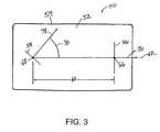
- FIG. 3is a schematic diagram illustrating an exemplary embodiment of an electromagnetic transmitter or receiver coil arrangement for an electromagnetic tracking system
- FIG. 4is a schematic diagram illustrating an exemplary embodiment of an electromagnetic transmitter or receiver coil arrangement for an electromagnetic tracking system.
- FIG. 1is a block diagram illustrating an exemplary embodiment of an electromagnetic tracking system 10 .
- the electromagnetic tracking system 10comprises at least one electromagnetic transmitter assembly 12 with one or more transmitter coils and at least one electromagnetic receiver assembly 14 with one or more receiver coils.
- the transmitter or receiver coilsare arranged to maximize the tracking accuracy and measure six degrees of freedom of the position and orientation of a medical device, implant or instrument.
- the electromagnetic tracking system 10further comprises a tracker workstation 20 coupled to and receiving data from the at least one electromagnetic transmitter assembly 12 and the at least one electromagnetic receiver assembly 14 , a user interface 30 coupled to the tracker workstation 20 , and a display 40 for visualizing imaging and tracking data.
- the tracker workstation 20includes a tracking system computer 22 and a tracker module 26 .
- the tracking system computer 22includes at least one processor 23 , a system controller 24 and memory 25 .
- the one or more coils of the electromagnetic transmitter and receiver assemblies 12 , 14may be built with various coil architectures.
- the one or more coils of the electromagnetic transmitter assembly 12may be single coils, a pair of single coils, industry-standard-coil-architecture (ISCA) type coils, a pair of ISCA type coils, multiple coils, or an array of coils.
- the one or more coils of the electromagnetic receiver assembly 14may be single coils, a pair of single coils, ISCA type coils, a pair of ISCA type coils, multiple coils, or an array of coils.
- ISCA type coilsare defined as three approximately collocated, approximately orthogonal, and approximately dipole coils. Therefore, ISCA electromagnetic transmitter and receiver coils would include three approximately collocated, approximately orthogonal, and approximately dipole coils for the transmitter assembly and three approximately collocated, approximately orthogonal, and approximately dipole coils for the receiver assembly. In other words, an ISCA configuration for the electromagnetic transmitter and receiver assemblies would include a three-axis dipole coil transmitter and a three-axis dipole coil receiver. In the ISCA configuration, the transmitter coils and the receiver coils are configured such that the three coils (i.e., coil trios) exhibit the same effective area, are oriented orthogonally to one another, and are centered at the same point.
- the three coilsi.e., coil trios
- the one or more coils of the at least one electromagnetic transmitter assembly 12may be characterized as single dipole coils and emit magnetic fields when a current is passed through the coils.
- multiple electromagnetic field generating coilsmay be used in coordination to generate multiple magnetic fields.
- the one or more coils of the at least one electromagnetic receiver assembly 14may be characterized as single dipole coils and detect the magnetic fields emitted by the at least one electromagnetic transmitter assembly 12 .
- the magnetic fields generated by the coilsmay induce a voltage into each coil of the at least one electromagnetic receiver assembly 14 .
- the induced voltageis indicative of the mutual inductance between the one or more coils of the at least one electromagnetic transmitter assembly 12 .
- the induced voltage across each coil of the at least one electromagnetic receiver assembly 14is detected and processed to determine the mutual inductance between each coil of the at least one electromagnetic transmitter assembly 12 and each coil of the at least one electromagnetic receiver assembly 14 .
- the magnetic field measurementsmay be used to calculate the position and orientation of the at least one electromagnetic transmitter assembly 12 with respect to the at least one electromagnetic receiver assembly 14 , or vice versa according to any suitable method or system.
- the detected magnetic field measurementsare digitized by electronics that may be included with the at least one electromagnetic receiver assembly 14 or the tracker module 26 .
- the magnetic field measurements or digitized signalsmay be transmitted from the at least one electromagnetic receiver assembly 14 to the tracking system computer 22 using wired or wireless communication protocols and interfaces.
- the digitized signals received by the tracking system computer 22represent magnetic field information detected by the at least one electromagnetic receiver assembly 14 .
- the digitized signalsare used to calculate position and orientation information of the at least one electromagnetic transmitter assembly 12 or the at least one electromagnetic receiver assembly 14 .
- the position and orientation informationis used to register the location of the at least one electromagnetic receiver assembly 14 or the at least one electromagnetic transmitter assembly 12 to acquired imaging data from an imaging system.
- the position and orientation datais visualized on the display 40 , showing in real-time the location of the at least one electromagnetic transmitter assembly 12 or the at least one electromagnetic receiver assembly 14 on pre-acquired or real-time images from the imaging system.
- the acquired imaging datamay be from a computed tomography (CT) imaging system, a magnetic resonance (MR) imaging system, a positron emission tomography (PET) imaging system, an ultrasound imaging system, an X-ray imaging system, or any suitable combination thereof. All six degrees of freedom (three of position (x, y, z) and three of orientation (roll, pitch, yaw)) of the at least one electromagnetic receiver assembly 14 or the at least one electromagnetic transmitter assembly 12 may be determined and tracked.
- the one or more coils of the electromagnetic transmitter and receiver assemblies 12 , 14are either precisely manufactured or precisely characterized during manufacture to obtain mathematical models of the one or more coils in the electromagnetic transmitter and receiver assemblies 12 , 14 . From the magnetic field measurements and mathematical models of the one or more coils, the position and orientation of the at least one electromagnetic receiver assembly 14 with respect to the at least one electromagnetic transmitter assembly 12 may be determined. Alternatively, the position and orientation of the at least one electromagnetic transmitter assembly 12 with respect to the at least one electromagnetic receiver assembly 14 may be determined.
- the at least one electromagnetic transmitter assembly 12may be a battery-powered wireless transmitter assembly, a passive transmitter assembly, or a wired transmitter assembly.
- the at least one electromagnetic receiver assembly 14may be a battery-powered wireless receiver assembly, a passive receiver assembly, or a wired receiver assembly.
- the tracker module 26may include drive circuitry configured to provide a drive current to each coil of the at least one electromagnetic transmitter assembly 12 .
- a drive currentmay be supplied by the drive circuitry to energize a coil of the at least one electromagnetic transmitter assembly 12 , and thereby generate an electromagnetic field that is detected by a coil of the at least one electromagnetic receiver assembly 14 .
- the drive currentmay be comprised of a periodic waveform with a given frequency (e.g., a sine wave, cosine wave or other periodic signal). The drive current supplied to a coil will generate an electromagnetic field at the same frequency as the drive current.
- the electromagnetic field generated by a coil of the at least one electromagnetic transmitter assembly 12induces a voltage indicative of the mutual inductance in a coil of the at least one electromagnetic receiver assembly 14 .
- the tracker module 26may include receiver data acquisition circuitry for receiving voltage and mutual inductance data from the at least one electromagnetic receiver assembly 14 .
- the tracking system computer 22may include at least one processor 23 , such as a digital signal processor, a CPU, or the like.
- the processor 23may process measured voltage and mutual inductance data from the at least one electromagnetic receiver assembly 14 to track the position and orientation of the at least one electromagnetic transmitter assembly 12 or the at least one electromagnetic receiver assembly 14 .
- the at least one processor 23may implement any suitable algorithm(s) to use the measured voltage signal indicative of the mutual inductance to calculate the position and orientation of the at least one electromagnetic receiver assembly 14 relative to the at least one electromagnetic transmitter assembly 12 , or the at least one electromagnetic transmitter assembly 12 relative to the at least one electromagnetic receiver assembly 14 .
- the at least one processor 23may use ratios of mutual inductance between each coil of the at least one electromagnetic receiver assembly 14 and each coil of the at least one electromagnetic transmitter assembly 12 to triangulate the relative positions of the coils. The at least one processor 23 may then use these relative positions to calculate the position and orientation of the at least one electromagnetic transmitter assembly 12 or the at least one electromagnetic receiver assembly 14 .
- the tracking system computer 22may include a system controller 24 .
- the system controller 24may control operations of the electromagnetic tracking system 10 .
- the tracking system computer 22may include memory 25 , which may be any processor-readable media that is accessible by the components of the tracker workstation 20 .
- the memory 25may be either volatile or non-volatile media.
- the memory 25may be either removable or non-removable media.
- Examples of processor-readable mediamay include (by way of example and not limitation): RAM (Random Access Memory), ROM (Read Only Memory), registers, cache, flash memory, storage devices, memory sticks, floppy disks, hard drives, CD-ROM, DVD-ROM, network storage, and the like.
- the user interface 30may include devices to facilitate the exchange of data and workflow between the system and the user.
- the user interface 30may include a keyboard, a mouse, a joystick, buttons, a touch screen display, or other devices providing user-selectable options, for example.
- the user interface 30may also include a printer or other peripheral devices.
- the display 40may be used for visualizing the position and orientation of a tracked object with respect to a processed image from an imaging system.
- the at least one electromagnetic receiver assembly 14may be attached to a medical device, implant or instrument 16 to be tracked and the at least one electromagnetic transmitter assembly 12 may generate at least one electromagnetic field to be received by the at least one electromagnetic receiver assembly 14 .
- the electromagnetic tracking system 10may track the position and orientation of the medical device, implant or instrument 16 during a medical procedure.
- the at least one electromagnetic transmitter assembly 12may be attached to a medical device, implant or instrument 16 to be tracked and the at least one electromagnetic receiver assembly 14 may be positioned within at least one electromagnetic field generated by the at least one electromagnetic transmitter assembly 12 .
- the electromagnetic tracking system 10enables a medical professional to continually track the position and orientation of the medical device, implant or instrument 16 during a medical procedure.
- the at least one electromagnetic transmitter and receiver assemblies 12 , 14may be wireless, with the coils being driven self-contained circuitry, data acquisitions being performed by self-contained circuitry, and power being provided by a self-contained power source.
- FIG. 2is a diagram illustrating an exemplary embodiment of an electromagnetic tracking system 100 .
- the electromagnetic tracking system 100comprises at least one electromagnetic transmitter assembly 112 with one or more coils positioned proximate to a patient 116 in a surgical field of interest and at least one electromagnetic receiver assembly 114 with two coils attachable to a trackable medical device, implant or instrument 118 to be tracked.
- the electromagnetic tracking system 100enables a medical professional to continually track the position and orientation of the medical device, implant or instrument 118 during a medical procedure.
- the two coils of the at least one electromagnetic receiver assembly 114may be attachable to a proximal end of the medical device, implant or instrument 118 , to track the position and orientation of the tip or distal end of the medical device, implant or instrument 118 .
- the two coilsinclude a first large coil with its axis aligned with the tip or distal end of the medical device, implant or instrument 118 and a second small coil positioned asymmetrically with respect to the first large coil.
- the first large coilprovides good medical device, implant or instrument 118 axis resolution.
- the electromagnetic tracking system 100further comprises a tracker workstation 120 coupled to and receiving data from the at least one electromagnetic transmitter assembly 112 and the at least one electromagnetic receiver assembly 114 , a user interface 130 coupled to the tracker workstation 120 , and a display 140 for visualizing imaging and tracking data.
- the tracker workstation 120includes a tracking system computer 122 and a tracker module 126 .
- the tracking system computer 122includes at least one processor 123 , a system controller 124 and memory 125 .
- the one or more coils of the at least one electromagnetic transmitter assembly 112may be characterized as single dipole coils and generate one or more magnetic fields when a current is applied to the one or more coils.
- the two coils of the at least one electromagnetic receiver assembly 114may also be characterized as single dipole coils and detect the one or more magnetic fields generated by the at least one electromagnetic transmitter assembly 112 .
- the one or more magnetic fields generated by the one or more coils of the at least one electromagnetic transmitter assembly 112may induce a voltage into each coil of the at least one electromagnetic receiver assembly 114 .
- the induced voltageis indicative of the mutual inductance between the one or more coils of the at least one electromagnetic transmitter assembly 112 .
- the induced voltage across each coil of the at least one electromagnetic receiver assembly 114is detected and processed to determine the mutual inductance between each coil of the at least one electromagnetic transmitter assembly 112 and each coil of the at least one electromagnetic receiver assembly 114 .
- the magnetic field measurementscan be used to calculate the position and orientation of the medical device, implant or instrument 118 according to any suitable method or system.
- the detected magnetic field measurementsare digitized by electronics that may be included with the at least one electromagnetic receiver assembly 114 or the tracker module 126 .
- the magnetic field measurements or digitized signalsmay be transmitted from the at least one electromagnetic receiver assembly 114 to the tracking system computer 122 using wired or wireless communication protocols and interfaces.
- the digitized signals received by the tracking system computer 122represent magnetic field information detected by the at least one electromagnetic receiver assembly 114 .
- the digitized signalsare used to calculate position and orientation information of the at least one electromagnetic transmitter assembly 112 or the at least one electromagnetic receiver assembly 114 .
- the position and orientation informationis used to register the location of the medical device, implant or instrument 118 to acquired imaging data from an imaging system.
- the position and orientation datais visualized on the display 140 , showing in real-time the location of the medical device, implant or instrument 118 on pre-acquired or real-time images from the imaging system.
- the display 140may be configured to show the real-time position and orientation of the medical device, implant or instrument 118 on a registered image of the patient's 116 anatomy.
- the acquired imaging datamay be from a CT imaging system, a MR imaging system, a PET imaging system, an ultrasound imaging system, an X-ray imaging system, or any suitable combination thereof. All six degrees of freedom (three of position (x, y, z) and three of orientation (roll, pitch, yaw)) of the medical device, implant or instrument 118 may be determined and tracked.
- the electromagnetic tracking system 100enables a medical professional to continually track the position and orientation of the medical device, implant or instrument 118 during a medical procedure.
- the at least one electromagnetic transmitter assembly 112may be a battery-powered wireless transmitter assembly, a passive transmitter assembly, or a wired transmitter assembly.
- the at least one electromagnetic receiver assembly 114may be a battery-powered wireless receiver assembly, a passive receiver assembly, or a wired receiver assembly.
- the at least one electromagnetic transmitter and receiver assemblies 112 , 114may be wireless, with the coils being driven by self-contained circuitry, data acquisitions being performed by self-contained circuitry, and power being provided by a self-contained power source.
- the electromagnetic tracking system 100is illustrated conceptually and may be implemented using any combination of dedicated hardware boards, digital signal processors, field programmable gate arrays, and processors.
- the tracker workstation 120may be implemented using an off-the-shelf computer with a single processor or multiple processors, with the functional operations distributed between processors.
- FIG. 3is a schematic diagram illustrating an exemplary embodiment of an electromagnetic transmitter or receiver coil arrangement 50 for an electromagnetic tracking system.
- the electromagnetic transmitter or receiver coil arrangement 50includes an asymmetrical two coil array 52 enclosed within a housing 54 .
- the two coil array 52includes a first large coil 56 and a second small coil 58 that are spaced apart from each other by a separation distance 60 .
- the second small coil 58is positioned asymmetrically with respect to the first large coil 56 .
- the housing 54provides for rigidly mounting the second small coil 58 with respect to the first large coil 56 .
- the housing 54may take the form of an enclosure coupled to the body of a medical device, implant or instrument.
- the first large coil 56 and the second small coil 58are configured in a distinctive geometric arrangement relative to each other to provide maximum accuracy and allow for all six degrees of freedom (x. y, z, roll, pitch, yaw) to be tracked.
- the first large coil 56 and the second small coil 58are angled at different orientations relative to a longitudinal axis 62 running from the center 66 of the first large coil 56 to the center 68 of the second small coil 58 .
- the second small coil 58may be angled at an angle 70 from the longitudinal axis 62
- the first large coil 56may be in-line with the longitudinal axis 62 .
- the second small coil's center 68is approximately on the large coil's axis 76 .
- the small coil's axis 78is angled, neither perpendicular to nor parallel with the large coil's axis 76 .
- the axes 76 , 78 of the two coils 56 , 58are pointed in different directions.
- the first large coil 56provides a large signal-to-noise ratio, and thus good accuracy of five degrees of freedom of the position and orientation of a medical device, implant or instrument being tracked, excluding roll about the first large coil's axis 76 .
- the second small coil 58provides determination of the first large coil's roll with low accuracy. The low accuracy is enough because the roll component of the first large coil's tip-offset vector is small.
- the phases of the coils' signal wavesare tracked and are subjected to a 180-degree ambiguity. This has the effect that each tracked orientation vector may or may not be multiplied by ⁇ 1. In other words, the sign of the magnetic moment or gain of the coils are not known.
- the mechanical asymmetry of the arrangement of the two coilspermits determination of the sign of the magnetic moment or gain of the coils.
- the second small coilallows determining the sign of the magnetic moment or gain of the first large coil.
- the tracked positions and the known mechanical relationship between the two coilsmay be used to calculate expected orientation vectors of the two coils. These two estimated orientation vectors will individually be approximately the same as or approximately the opposite-direction to the tracked orientation vectors. Reversing the direction of the tracked orientations vectors is needed to make the tracked orientation vectors agree with the expected orientation vectors.
- FIG. 4is a schematic diagram illustrating an exemplary embodiment of an electromagnetic transmitter or receiver coil arrangement 80 for an electromagnetic tracking system.
- the electromagnetic transmitter or receiver coil arrangement 80includes an asymmetrical two coil array 82 enclosed within a housing 84 .
- the two coil array 82includes a first large coil 86 and a second small coil 88 that are spaced apart from each other with the second small coil 88 positioned asymmetrically with respect to the first large coil 86 .
- the housing 84provides for rigidly mounting the second small coil 88 with respect to the first large coil 86 .
- the housing 84may take the form of an enclosure coupled to the body of a medical device, implant or instrument.
- the first large coil 86 and the second small coil 88are arranged asymmetrically to each other to provide maximum accuracy and allow for all six degrees of freedom (x. y, z, roll, pitch, yaw) of position and orientation of a medical device, implant or instrument to be tracked.
- the first large coil 86 and the second small coil 88are angled at different orientations.
- the angle of the second small coil 88 with respect to a longitudinal axis 92 extending through the centers of the coils 86 , 88is neither perpendicular to nor parallel with the angle of the first large coil 86 with respect to the longitudinal axis 92 .
- the two coils 86 , 88may be ISCA type coils, each with three approximately collocated, approximately orthogonal, and approximately dipole coils (i.e., coil trios).
- the coil triosexhibit the same effective area, are oriented orthogonally to one another, and are centered at the same point.
- a method of maximizing the tracking accuracy of an electromagnetic tracking systemcomprises attaching a first large coil and a second small coil to an object to be tracked, and determining the position and orientation of the object to be tracked.
- the second small coilmay be positioned asymmetrically with respect to the first large coil.
- the step of determining the position and orientation of the object to be trackedmay include applying a drive current to at least one coil of a transmitter assembly, measuring the magnetic field generated by the at least one coil of the transmitter assembly and received by at least one coil of a receiver assembly, and using the magnetic field measurements to calculate the position and orientation of the object to be tracked.
- the object to be trackedmay be a medical device, implant or instrument.
- Logical connectionsmay include a local area network (LAN) and a wide area network (WAN) that are presented here by way of example and not limitation.
- LANlocal area network
- WANwide area network
- Such networking environmentsare commonplace in office-wide or enterprise-wide computer networks, intranets and the Internet and may use a wide variety of different communication protocols.
- Those skilled in the artwill appreciate that such network computing environments will typically encompass many types of computer system configurations, including personal computers, hand-held devices, multi-processor systems, microprocessor-based or programmable consumer electronics, network PCs, minicomputers, mainframe computers, and the like.
- Embodiments of the inventionmay also be practiced in distributed computing environments where tasks are performed by local and remote processing devices that are linked (either by hardwired links, wireless links, or by a combination of hardwired or wireless links) through a communications network.
- program modulesmay be located in both local and remote memory storage devices.
- An exemplary system for implementing the overall system or portions of the systemmight include a general purpose computing device in the form of a computer, including a processing unit, a system memory, and a system bus that couples various system components including the system memory to the processing unit.
- the system memorymay include read only memory (ROM) and random access memory (RAM).
- the computermay also include a magnetic hard disk drive for reading from and writing to a magnetic hard disk, a magnetic disk drive for reading from or writing to a removable magnetic disk, and an optical disk drive for reading from or writing to a removable optical disk such as a CD ROM or other optical media.
- the drives and their associated machine-readable mediaprovide nonvolatile storage of machine-executable instructions, data structures, program modules and other data for the computer.
Landscapes
- Health & Medical Sciences (AREA)
- Life Sciences & Earth Sciences (AREA)
- Engineering & Computer Science (AREA)
- Physics & Mathematics (AREA)
- Surgery (AREA)
- Medical Informatics (AREA)
- Biomedical Technology (AREA)
- Heart & Thoracic Surgery (AREA)
- Robotics (AREA)
- Molecular Biology (AREA)
- Animal Behavior & Ethology (AREA)
- General Health & Medical Sciences (AREA)
- Public Health (AREA)
- Veterinary Medicine (AREA)
- Nuclear Medicine, Radiotherapy & Molecular Imaging (AREA)
- Condensed Matter Physics & Semiconductors (AREA)
- General Physics & Mathematics (AREA)
- Measurement Of Length, Angles, Or The Like Using Electric Or Magnetic Means (AREA)
Abstract
Description
Claims (24)
Priority Applications (1)
| Application Number | Priority Date | Filing Date | Title |
|---|---|---|---|
| US11/870,854US8391952B2 (en) | 2007-10-11 | 2007-10-11 | Coil arrangement for an electromagnetic tracking system |
Applications Claiming Priority (1)
| Application Number | Priority Date | Filing Date | Title |
|---|---|---|---|
| US11/870,854US8391952B2 (en) | 2007-10-11 | 2007-10-11 | Coil arrangement for an electromagnetic tracking system |
Publications (2)
| Publication Number | Publication Date |
|---|---|
| US20090096443A1 US20090096443A1 (en) | 2009-04-16 |
| US8391952B2true US8391952B2 (en) | 2013-03-05 |
Family
ID=40533556
Family Applications (1)
| Application Number | Title | Priority Date | Filing Date |
|---|---|---|---|
| US11/870,854Expired - Fee RelatedUS8391952B2 (en) | 2007-10-11 | 2007-10-11 | Coil arrangement for an electromagnetic tracking system |
Country Status (1)
| Country | Link |
|---|---|
| US (1) | US8391952B2 (en) |
Cited By (19)
| Publication number | Priority date | Publication date | Assignee | Title |
|---|---|---|---|---|
| US20140002069A1 (en)* | 2012-06-27 | 2014-01-02 | Kenneth Stoddard | Eddy current probe |
| US20140275981A1 (en)* | 2013-03-13 | 2014-09-18 | Sean P. Selover | Methods, systems, and devices for guiding surgical instruments using radio frequency technology |
| US9530219B2 (en) | 2014-07-02 | 2016-12-27 | Covidien Lp | System and method for detecting trachea |
| US9603668B2 (en) | 2014-07-02 | 2017-03-28 | Covidien Lp | Dynamic 3D lung map view for tool navigation inside the lung |
| US20170202611A1 (en)* | 2014-05-28 | 2017-07-20 | Taewoong Medical Co., Ltd. | Device and method for detecting position of electrode inserted into human body |
| US9754367B2 (en) | 2014-07-02 | 2017-09-05 | Covidien Lp | Trachea marking |
| US9770216B2 (en) | 2014-07-02 | 2017-09-26 | Covidien Lp | System and method for navigating within the lung |
| US9836848B2 (en) | 2014-07-02 | 2017-12-05 | Covidien Lp | System and method for segmentation of lung |
| US10285760B2 (en) | 2015-02-04 | 2019-05-14 | Queen's University At Kingston | Methods and apparatus for improved electromagnetic tracking and localization |
| US10709352B2 (en) | 2015-10-27 | 2020-07-14 | Covidien Lp | Method of using lung airway carina locations to improve ENB registration |
| US10765483B2 (en) | 2017-04-20 | 2020-09-08 | Medtronic Navigation, Inc. | Navigation system and method |
| US10772532B2 (en) | 2014-07-02 | 2020-09-15 | Covidien Lp | Real-time automatic registration feedback |
| US10782114B2 (en) | 2016-12-20 | 2020-09-22 | Boston Scientific Scimed Inc. | Hybrid navigation sensor |
| US10835151B2 (en) | 2017-02-06 | 2020-11-17 | Boston Scientific Scimed Inc. | Sensor assemblies for electromagnetic navigation systems |
| USD916749S1 (en) | 2014-07-02 | 2021-04-20 | Covidien Lp | Display screen or portion thereof with graphical user interface |
| US10986990B2 (en) | 2015-09-24 | 2021-04-27 | Covidien Lp | Marker placement |
| US11058321B2 (en) | 2016-12-20 | 2021-07-13 | Boston Scientific Scimed Inc. | Current driven sensor for magnetic navigation |
| US11224392B2 (en) | 2018-02-01 | 2022-01-18 | Covidien Lp | Mapping disease spread |
| US12089902B2 (en) | 2019-07-30 | 2024-09-17 | Coviden Lp | Cone beam and 3D fluoroscope lung navigation |
Families Citing this family (16)
| Publication number | Priority date | Publication date | Assignee | Title |
|---|---|---|---|---|
| US8450997B2 (en) | 2009-04-28 | 2013-05-28 | Brown University | Electromagnetic position and orientation sensing system |
| WO2012134246A2 (en) | 2011-04-01 | 2012-10-04 | 엘지전자 주식회사 | Entropy decoding method, and decoding apparatus using same |
| US10238837B2 (en) | 2011-10-14 | 2019-03-26 | Intuitive Surgical Operations, Inc. | Catheters with control modes for interchangeable probes |
| US9452276B2 (en) | 2011-10-14 | 2016-09-27 | Intuitive Surgical Operations, Inc. | Catheter with removable vision probe |
| US9387048B2 (en)* | 2011-10-14 | 2016-07-12 | Intuitive Surgical Operations, Inc. | Catheter sensor systems |
| US20130303944A1 (en) | 2012-05-14 | 2013-11-14 | Intuitive Surgical Operations, Inc. | Off-axis electromagnetic sensor |
| DE102012017387A1 (en) | 2012-09-01 | 2014-03-06 | Volkswagen Aktiengesellschaft | A method for determining a position of a receiver and location system for a receiver |
| JP2014151102A (en)* | 2013-02-13 | 2014-08-25 | Olympus Corp | Relative position detection system for tubular device and endoscope apparatus |
| AU2016228986B2 (en)* | 2015-03-10 | 2021-02-04 | Stent Tek Limited | Surgical system, device and methods of use thereof for the percutaneous creation of an arteriovenous fistula (AVF) |
| WO2016182559A1 (en)* | 2015-05-12 | 2016-11-17 | Purdue Research Foundation | Wireless position sensing using magnetic field of single transmitter |
| US10196927B2 (en)* | 2015-12-09 | 2019-02-05 | General Electric Company | System and method for locating a probe within a gas turbine engine |
| US10196922B2 (en)* | 2015-12-09 | 2019-02-05 | General Electric Company | System and method for locating a probe within a gas turbine engine |
| US10489896B2 (en) | 2017-11-14 | 2019-11-26 | General Electric Company | High dynamic range video capture using variable lighting |
| US10488349B2 (en) | 2017-11-14 | 2019-11-26 | General Electric Company | Automated borescope insertion system |
| US10775315B2 (en) | 2018-03-07 | 2020-09-15 | General Electric Company | Probe insertion system |
| CN112601500B (en) | 2018-04-20 | 2025-08-15 | 斯滕特泰克有限公司 | Apparatus and method for directional display and alignment in a percutaneous device |
Citations (135)
| Publication number | Priority date | Publication date | Assignee | Title |
|---|---|---|---|---|
| US3121228A (en) | 1961-05-01 | 1964-02-11 | Henry P Kalmus | Direction indicator |
| US3392390A (en) | 1965-03-15 | 1968-07-09 | Marconi Co Ltd | Aircraft radio landing aids for determining the position of an aircraft in space relative to a predetermined glidepath |
| US3529682A (en) | 1968-10-03 | 1970-09-22 | Bell Telephone Labor Inc | Location detection and guidance systems for burrowing device |
| US3828867A (en) | 1972-05-15 | 1974-08-13 | A Elwood | Low frequency drill bit apparatus and method of locating the position of the drill head below the surface of the earth |
| US3868565A (en) | 1973-07-30 | 1975-02-25 | Jack Kuipers | Object tracking and orientation determination means, system and process |
| US3983474A (en) | 1975-02-21 | 1976-09-28 | Polhemus Navigation Sciences, Inc. | Tracking and determining orientation of object using coordinate transformation means, system and process |
| US4054881A (en) | 1976-04-26 | 1977-10-18 | The Austin Company | Remote object position locater |
| US4314251A (en) | 1979-07-30 | 1982-02-02 | The Austin Company | Remote object position and orientation locater |
| US4613866A (en) | 1983-05-13 | 1986-09-23 | Mcdonnell Douglas Corporation | Three dimensional digitizer with electromagnetic coupling |
| US4618822A (en) | 1984-04-18 | 1986-10-21 | Position Orientation Systems, Ltd. | Displacement sensing device utilizing adjustable tuned circuit |
| US4622644A (en) | 1984-05-10 | 1986-11-11 | Position Orientation Systems, Ltd. | Magnetic position and orientation measurement system |
| US4642786A (en) | 1984-05-25 | 1987-02-10 | Position Orientation Systems, Ltd. | Method and apparatus for position and orientation measurement using a magnetic field and retransmission |
| US4710708A (en) | 1981-04-27 | 1987-12-01 | Develco | Method and apparatus employing received independent magnetic field components of a transmitted alternating magnetic field for determining location |
| US4737794A (en) | 1985-12-09 | 1988-04-12 | Mcdonnell Douglas Corporation | Method and apparatus for determining remote object orientation and position |
| US4742356A (en) | 1985-12-09 | 1988-05-03 | Mcdonnell Douglas Corporation | Method and apparatus for determining remote object orientation and position |
| US4812812A (en) | 1986-10-23 | 1989-03-14 | Gas Research Institute, Inc. | Apparatus and method for determining the position and orientation of a remote object |
| US4849692A (en) | 1986-10-09 | 1989-07-18 | Ascension Technology Corporation | Device for quantitatively measuring the relative position and orientation of two bodies in the presence of metals utilizing direct current magnetic fields |
| US4945305A (en) | 1986-10-09 | 1990-07-31 | Ascension Technology Corporation | Device for quantitatively measuring the relative position and orientation of two bodies in the presence of metals utilizing direct current magnetic fields |
| US5099845A (en) | 1989-05-24 | 1992-03-31 | Micronix Pty Ltd. | Medical instrument location means |
| US5172056A (en) | 1990-08-03 | 1992-12-15 | Sextant Avionique | Magnetic field transmitter and receive using helmholtz coils for detecting object position and orientation |
| US5211165A (en) | 1991-09-03 | 1993-05-18 | General Electric Company | Tracking system to follow the position and orientation of a device with radiofrequency field gradients |
| US5245307A (en) | 1989-04-18 | 1993-09-14 | Institut Dr. Friedrich Forster Pruferatebau Gmbh & Co. Kg | Search coil assembly for electrically conductive object detection |
| US5251635A (en) | 1991-09-03 | 1993-10-12 | General Electric Company | Stereoscopic X-ray fluoroscopy system using radiofrequency fields |
| US5255680A (en) | 1991-09-03 | 1993-10-26 | General Electric Company | Automatic gantry positioning for imaging systems |
| US5265610A (en) | 1991-09-03 | 1993-11-30 | General Electric Company | Multi-planar X-ray fluoroscopy system using radiofrequency fields |
| US5307072A (en) | 1992-07-09 | 1994-04-26 | Polhemus Incorporated | Non-concentricity compensation in position and orientation measurement systems |
| US5307808A (en) | 1992-04-01 | 1994-05-03 | General Electric Company | Tracking system and pulse sequences to monitor the position of a device using magnetic resonance |
| US5377678A (en) | 1991-09-03 | 1995-01-03 | General Electric Company | Tracking system to follow the position and orientation of a device with radiofrequency fields |
| US5437277A (en) | 1991-11-18 | 1995-08-01 | General Electric Company | Inductively coupled RF tracking system for use in invasive imaging of a living body |
| US5443066A (en) | 1991-11-18 | 1995-08-22 | General Electric Company | Invasive system employing a radiofrequency tracking system |
| US5453686A (en) | 1993-04-08 | 1995-09-26 | Polhemus Incorporated | Pulsed-DC position and orientation measurement system |
| US5558091A (en) | 1993-10-06 | 1996-09-24 | Biosense, Inc. | Magnetic determination of position and orientation |
| US5592939A (en) | 1995-06-14 | 1997-01-14 | Martinelli; Michael A. | Method and system for navigating a catheter probe |
| US5600330A (en) | 1994-07-12 | 1997-02-04 | Ascension Technology Corporation | Device for measuring position and orientation using non-dipole magnet IC fields |
| US5640170A (en) | 1995-06-05 | 1997-06-17 | Polhemus Incorporated | Position and orientation measuring system having anti-distortion source configuration |
| US5676673A (en) | 1994-09-15 | 1997-10-14 | Visualization Technology, Inc. | Position tracking and imaging system with error detection for use in medical applications |
| US5747996A (en) | 1994-03-09 | 1998-05-05 | U.S. Philips Corporation | Device for determining the spatial position of a sensor element which is displacement relative to a reference element |
| US5767669A (en) | 1996-06-14 | 1998-06-16 | Ascension Technology Corporation | Magnetic field position and orientation measurement system with dynamic eddy current rejection |
| US5782765A (en) | 1996-04-25 | 1998-07-21 | Medtronic, Inc. | Medical positioning system |
| US5829444A (en) | 1994-09-15 | 1998-11-03 | Visualization Technology, Inc. | Position tracking and imaging system for use in medical applications |
| US5847976A (en) | 1995-06-01 | 1998-12-08 | Sextant Avionique | Method to determine the position and orientation of a mobile system, especially the line of sight in a helmet visor |
| US5913820A (en) | 1992-08-14 | 1999-06-22 | British Telecommunications Public Limited Company | Position location system |
| US5953683A (en) | 1997-10-09 | 1999-09-14 | Ascension Technology Corporation | Sourceless orientation sensor |
| US6052610A (en) | 1998-01-09 | 2000-04-18 | International Business Machines Corporation | Magnetic catheter tracker and method therefor |
| US6073043A (en) | 1997-12-22 | 2000-06-06 | Cormedica Corporation | Measuring position and orientation using magnetic fields |
| US6129668A (en) | 1997-05-08 | 2000-10-10 | Lucent Medical Systems, Inc. | System and method to determine the location and orientation of an indwelling medical device |
| US6129667A (en) | 1998-02-02 | 2000-10-10 | General Electric Company | Luminal diagnostics employing spectral analysis |
| US6161032A (en) | 1998-03-30 | 2000-12-12 | Biosense, Inc. | Three-axis coil sensor |
| US6172499B1 (en) | 1999-10-29 | 2001-01-09 | Ascension Technology Corporation | Eddy current error-reduced AC magnetic position measurement system |
| US6177792B1 (en) | 1996-03-26 | 2001-01-23 | Bisense, Inc. | Mutual induction correction for radiator coils of an objects tracking system |
| US6188355B1 (en) | 1997-12-12 | 2001-02-13 | Super Dimension Ltd. | Wireless six-degree-of-freedom locator |
| US6201387B1 (en)* | 1997-10-07 | 2001-03-13 | Biosense, Inc. | Miniaturized position sensor having photolithographic coils for tracking a medical probe |
| US6201987B1 (en) | 1998-05-26 | 2001-03-13 | General Electric Company | Error compensation for device tracking systems employing electromagnetic fields |
| US6203493B1 (en) | 1996-02-15 | 2001-03-20 | Biosense, Inc. | Attachment with one or more sensors for precise position determination of endoscopes |
| US6211666B1 (en) | 1996-02-27 | 2001-04-03 | Biosense, Inc. | Object location system and method using field actuation sequences having different field strengths |
| US6226547B1 (en) | 1997-11-15 | 2001-05-01 | Roke Manor Research Limited | Catheter tracking system |
| US6230038B1 (en) | 1999-02-01 | 2001-05-08 | International Business Machines Corporation | Imaging of internal structures of living bodies by sensing implanted magnetic devices |
| US6233476B1 (en) | 1999-05-18 | 2001-05-15 | Mediguide Ltd. | Medical positioning system |
| US6246231B1 (en) | 1999-07-29 | 2001-06-12 | Ascension Technology Corporation | Magnetic field permeable barrier for magnetic position measurement system |
| US6266552B1 (en)* | 1996-06-28 | 2001-07-24 | Siemens-Elema Ab | Method and arrangement for locating a measurement and/or treatment catheter in a vessel or organ of a patient |
| US6285902B1 (en) | 1999-02-10 | 2001-09-04 | Surgical Insights, Inc. | Computer assisted targeting device for use in orthopaedic surgery |
| US20010045826A1 (en) | 2000-03-16 | 2001-11-29 | Schneider Mark R. | Distortion immune magnetic field generator for magnetic tracking systems and method of generating magnetic fields |
| US20010047133A1 (en) | 1998-08-02 | 2001-11-29 | Super Dimension Ltd. | Imaging device with magnetically permeable compensator |
| US6366799B1 (en) | 1996-02-15 | 2002-04-02 | Biosense, Inc. | Movable transmit or receive coils for location system |
| US6369564B1 (en) | 1999-11-01 | 2002-04-09 | Polhemus, Inc. | Electromagnetic position and orientation tracking system with distortion compensation employing wireless sensors |
| US20020045812A1 (en) | 1996-02-01 | 2002-04-18 | Shlomo Ben-Haim | Implantable sensor for determining position coordinates |
| US6377041B1 (en) | 1998-12-17 | 2002-04-23 | Polhemus Inc. | Method and apparatus for determining electromagnetic field characteristics within a volume |
| US6400139B1 (en) | 1999-11-01 | 2002-06-04 | Polhemus Inc. | Methods and apparatus for electromagnetic position and orientation tracking with distortion compensation |
| US6427079B1 (en) | 1999-08-09 | 2002-07-30 | Cormedica Corporation | Position and orientation measuring with magnetic fields |
| US6472975B1 (en) | 1994-06-20 | 2002-10-29 | Avid Marketing, Inc. | Electronic identification system with improved sensitivity |
| US6474341B1 (en) | 1999-10-28 | 2002-11-05 | Surgical Navigation Technologies, Inc. | Surgical communication and power system |
| US6478802B2 (en) | 2000-06-09 | 2002-11-12 | Ge Medical Systems Global Technology Company, Llc | Method and apparatus for display of an image guided drill bit |
| US6484049B1 (en) | 2000-04-28 | 2002-11-19 | Ge Medical Systems Global Technology Company, Llc | Fluoroscopic tracking and visualization system |
| US6493573B1 (en) | 1999-10-28 | 2002-12-10 | Winchester Development Associates | Method and system for navigating a catheter probe in the presence of field-influencing objects |
| US6516213B1 (en) | 1999-09-03 | 2003-02-04 | Robin Medical, Inc. | Method and apparatus to estimate location and orientation of objects during magnetic resonance imaging |
| US6528991B2 (en) | 2001-07-03 | 2003-03-04 | Ascension Technology Corporation | Magnetic position measurement system with field containment means |
| US6534982B1 (en) | 1998-12-23 | 2003-03-18 | Peter D. Jakab | Magnetic resonance scanner with electromagnetic position and orientation tracking device |
| US6553326B1 (en) | 2000-04-07 | 2003-04-22 | Northern Digital Inc. | Errors in systems using magnetic fields to locate objects |
| US6584301B1 (en) | 2000-05-25 | 2003-06-24 | Motorola, Inc. | Inductive reader device and method with integrated antenna and signal coupler |
| US6624626B2 (en) | 1999-11-01 | 2003-09-23 | Polhemus Inc. | Method and apparatus for electromagnetic position and orientation tracking with distortion compensation employing modulated signal |
| US6625563B2 (en) | 2001-06-26 | 2003-09-23 | Northern Digital Inc. | Gain factor and position determination system |
| US6636757B1 (en) | 2001-06-04 | 2003-10-21 | Surgical Navigation Technologies, Inc. | Method and apparatus for electromagnetic navigation of a surgical probe near a metal object |
| US6656135B2 (en) | 2000-05-01 | 2003-12-02 | Southwest Research Institute | Passive and wireless displacement measuring device |
| US6667612B2 (en) | 2000-07-31 | 2003-12-23 | Commissariat A L'energie Atomique | Short-distance locating system |
| US20040011365A1 (en) | 2002-07-18 | 2004-01-22 | Assaf Govari | Medical sensor having power coil, sensing coil and control chip |
| US6701179B1 (en) | 1999-10-28 | 2004-03-02 | Michael A. Martinelli | Coil structures and methods for generating magnetic fields |
| US6711429B1 (en) | 1998-09-24 | 2004-03-23 | Super Dimension Ltd. | System and method for determining the location of a catheter during an intra-body medical procedure |
| US20040068178A1 (en) | 2002-09-17 | 2004-04-08 | Assaf Govari | High-gradient recursive locating system |
| US20040073228A1 (en) | 2002-10-11 | 2004-04-15 | Kienzle Thomas C. | Adjustable instruments for use with an electromagnetic localizer |
| US20040077940A1 (en) | 2002-10-11 | 2004-04-22 | Kienzle Thomas C. | Instrument guide for use with a tracking system |
| US20040102696A1 (en) | 2002-11-22 | 2004-05-27 | Assaf Govari | Dynamic metal immunity |
| US6754596B2 (en) | 2002-11-01 | 2004-06-22 | Ascension Technology Corporation | Method of measuring position and orientation with improved signal to noise ratio |
| US6774624B2 (en) | 2002-03-27 | 2004-08-10 | Ge Medical Systems Global Technology Company, Llc | Magnetic tracking system |
| US6783536B2 (en) | 2001-12-14 | 2004-08-31 | Brainlab Ag | Magnetic catheter navigation |
| US6784660B2 (en) | 2002-03-18 | 2004-08-31 | Ascension Technology Corporation | Magnetic position and orientation measurement system with magnetic field permeable attenuator |
| US6803757B2 (en) | 2001-10-02 | 2004-10-12 | Bentley Nevada, Llc | Multi-coil eddy current proximity probe system |
| US20040207389A1 (en) | 2003-04-17 | 2004-10-21 | Nieminen John M. | Eddy current detection and compensation |
| US6812842B2 (en) | 2001-12-20 | 2004-11-02 | Calypso Medical Technologies, Inc. | System for excitation of a leadless miniature marker |
| US6836745B2 (en) | 2000-07-26 | 2004-12-28 | Northern Digital Inc. | Method for determining the position of a sensor element |
| US6838873B2 (en) | 2001-10-30 | 2005-01-04 | Scientific Generics Ltd. | Position sensor |
| US20050012597A1 (en) | 2003-07-02 | 2005-01-20 | Anderson Peter Traneus | Wireless electromagnetic tracking system using a nonlinear passive transponder |
| US6856826B2 (en) | 2000-04-28 | 2005-02-15 | Ge Medical Systems Global Technology Company, Llc | Fluoroscopic tracking and visualization system |
| US6856827B2 (en) | 2000-04-28 | 2005-02-15 | Ge Medical Systems Global Technology Company, Llc | Fluoroscopic tracking and visualization system |
| US6856823B2 (en) | 2002-06-18 | 2005-02-15 | Ascension Technology Corporation | Spiral magnetic transmitter for position measurement system |
| US20050049485A1 (en) | 2003-08-27 | 2005-03-03 | Harmon Kim R. | Multiple configuration array for a surgical navigation system |
| US20050059883A1 (en) | 2003-09-12 | 2005-03-17 | Peterson Thomas Herbert | System and method for determining the position of a flexible instrument used in a tracking system |
| US20050065433A1 (en) | 2003-09-24 | 2005-03-24 | Anderson Peter Traneus | System and method for software configurable electromagnetic tracking |
| US20050062469A1 (en)* | 2003-09-23 | 2005-03-24 | Anderson Peter Traneus | System and method for hemisphere disambiguation in electromagnetic tracking systems |
| US6887245B2 (en) | 2001-06-11 | 2005-05-03 | Ge Medical Systems Global Technology Company, Llc | Surgical drill for use with a computer assisted surgery system |
| US20050104776A1 (en) | 2003-11-14 | 2005-05-19 | Anderson Peter T. | Electromagnetic tracking system and method using a three-coil wireless transmitter |
| US20050107687A1 (en) | 2003-11-14 | 2005-05-19 | Anderson Peter T. | System and method for distortion reduction in an electromagnetic tracker |
| US20050222793A1 (en) | 2004-04-02 | 2005-10-06 | Lloyd Charles F | Method and system for calibrating deformed instruments |
| US20050228270A1 (en) | 2004-04-02 | 2005-10-13 | Lloyd Charles F | Method and system for geometric distortion free tracking of 3-dimensional objects from 2-dimensional measurements |
| US20050245821A1 (en) | 2004-03-05 | 2005-11-03 | Assaf Govari | Position sensing system for orthopedic applications |
| US6968846B2 (en) | 2002-03-07 | 2005-11-29 | Stereotaxis, Inc. | Method and apparatus for refinably accurate localization of devices and instruments in scattering environments |
| US20050288574A1 (en) | 2004-06-23 | 2005-12-29 | Thornton Thomas M | Wireless (disposable) fiducial based registration and EM distoration based surface registration |
| US20060020915A1 (en) | 2004-07-22 | 2006-01-26 | General Electric Company | System and method for improved surgical workflow development |
| US20060025668A1 (en) | 2004-08-02 | 2006-02-02 | Peterson Thomas H | Operating table with embedded tracking technology |
| US20060030771A1 (en) | 2004-08-03 | 2006-02-09 | Lewis Levine | System and method for sensor integration |
| US20060055712A1 (en) | 2004-08-24 | 2006-03-16 | Anderson Peter T | Method and system for field mapping using integral methodology |
| US20060058604A1 (en) | 2004-08-25 | 2006-03-16 | General Electric Company | System and method for hybrid tracking in surgical navigation |
| US20060079756A1 (en) | 2004-10-07 | 2006-04-13 | Lloyd Charles F | Method and system for positioning a tracking sensor for optimal accuracy |
| US20060115054A1 (en) | 2004-11-12 | 2006-06-01 | General Electric Company | System and method for integration of a calibration target into a C-arm |
| US20060121849A1 (en) | 2003-07-01 | 2006-06-08 | Peter Traneus Anderson | Electromagnetic coil array integrated into flat-panel detector |
| US7097357B2 (en) | 2004-06-02 | 2006-08-29 | General Electric Company | Method and system for improved correction of registration error in a fluoroscopic image |
| US7139601B2 (en) | 1993-04-26 | 2006-11-21 | Surgical Navigation Technologies, Inc. | Surgical navigation systems including reference and localization frames |
| US20060262029A1 (en) | 2005-05-19 | 2006-11-23 | General Electric Company | Method for fabricating an antenna |
| US7153308B2 (en) | 2003-05-14 | 2006-12-26 | Ge Medical Systems Global Technology Company, Llc | Universal attachment mechanism for attaching a surgical tracking device to an instrument |
| US7153297B2 (en) | 2003-11-03 | 2006-12-26 | Ge Medical Systems Global Technolgoy Company, Llc | Universal attachment mechanism for attaching a tracking device to an instrument |
| US20070129629A1 (en) | 2005-11-23 | 2007-06-07 | Beauregard Gerald L | System and method for surgical navigation |
| US20070164895A1 (en) | 2005-11-30 | 2007-07-19 | General Electric Company | System and method for disambiguating the phase of a field received from a transmitter in an electromagnetic tracking system |
| US20070167744A1 (en) | 2005-11-23 | 2007-07-19 | General Electric Company | System and method for surgical navigation cross-reference to related applications |
| US20070211927A1 (en) | 2006-03-09 | 2007-09-13 | General Electric Company | Methods and systems for registration of surgical navigation data and image data |
| US20070238980A1 (en) | 2006-03-29 | 2007-10-11 | General Electric Company | Conformal Coil Array for a Medical Tracking System |
| US7809421B1 (en)* | 2000-07-20 | 2010-10-05 | Biosense, Inc. | Medical system calibration with static metal compensation |
- 2007
- 2007-10-11USUS11/870,854patent/US8391952B2/ennot_activeExpired - Fee Related
Patent Citations (162)
| Publication number | Priority date | Publication date | Assignee | Title |
|---|---|---|---|---|
| US3121228A (en) | 1961-05-01 | 1964-02-11 | Henry P Kalmus | Direction indicator |
| US3392390A (en) | 1965-03-15 | 1968-07-09 | Marconi Co Ltd | Aircraft radio landing aids for determining the position of an aircraft in space relative to a predetermined glidepath |
| US3529682A (en) | 1968-10-03 | 1970-09-22 | Bell Telephone Labor Inc | Location detection and guidance systems for burrowing device |
| US3828867A (en) | 1972-05-15 | 1974-08-13 | A Elwood | Low frequency drill bit apparatus and method of locating the position of the drill head below the surface of the earth |
| US3868565A (en) | 1973-07-30 | 1975-02-25 | Jack Kuipers | Object tracking and orientation determination means, system and process |
| US3983474A (en) | 1975-02-21 | 1976-09-28 | Polhemus Navigation Sciences, Inc. | Tracking and determining orientation of object using coordinate transformation means, system and process |
| US4054881A (en) | 1976-04-26 | 1977-10-18 | The Austin Company | Remote object position locater |
| US4314251A (en) | 1979-07-30 | 1982-02-02 | The Austin Company | Remote object position and orientation locater |
| US4710708A (en) | 1981-04-27 | 1987-12-01 | Develco | Method and apparatus employing received independent magnetic field components of a transmitted alternating magnetic field for determining location |
| US4613866A (en) | 1983-05-13 | 1986-09-23 | Mcdonnell Douglas Corporation | Three dimensional digitizer with electromagnetic coupling |
| US4618822A (en) | 1984-04-18 | 1986-10-21 | Position Orientation Systems, Ltd. | Displacement sensing device utilizing adjustable tuned circuit |
| US4622644A (en) | 1984-05-10 | 1986-11-11 | Position Orientation Systems, Ltd. | Magnetic position and orientation measurement system |
| US4642786A (en) | 1984-05-25 | 1987-02-10 | Position Orientation Systems, Ltd. | Method and apparatus for position and orientation measurement using a magnetic field and retransmission |
| US4742356A (en) | 1985-12-09 | 1988-05-03 | Mcdonnell Douglas Corporation | Method and apparatus for determining remote object orientation and position |
| US4737794A (en) | 1985-12-09 | 1988-04-12 | Mcdonnell Douglas Corporation | Method and apparatus for determining remote object orientation and position |
| US4849692A (en) | 1986-10-09 | 1989-07-18 | Ascension Technology Corporation | Device for quantitatively measuring the relative position and orientation of two bodies in the presence of metals utilizing direct current magnetic fields |
| US4945305A (en) | 1986-10-09 | 1990-07-31 | Ascension Technology Corporation | Device for quantitatively measuring the relative position and orientation of two bodies in the presence of metals utilizing direct current magnetic fields |
| US4812812A (en) | 1986-10-23 | 1989-03-14 | Gas Research Institute, Inc. | Apparatus and method for determining the position and orientation of a remote object |
| US5245307A (en) | 1989-04-18 | 1993-09-14 | Institut Dr. Friedrich Forster Pruferatebau Gmbh & Co. Kg | Search coil assembly for electrically conductive object detection |
| US5099845A (en) | 1989-05-24 | 1992-03-31 | Micronix Pty Ltd. | Medical instrument location means |
| US5172056A (en) | 1990-08-03 | 1992-12-15 | Sextant Avionique | Magnetic field transmitter and receive using helmholtz coils for detecting object position and orientation |
| US5211165A (en) | 1991-09-03 | 1993-05-18 | General Electric Company | Tracking system to follow the position and orientation of a device with radiofrequency field gradients |
| US5251635A (en) | 1991-09-03 | 1993-10-12 | General Electric Company | Stereoscopic X-ray fluoroscopy system using radiofrequency fields |
| US5255680A (en) | 1991-09-03 | 1993-10-26 | General Electric Company | Automatic gantry positioning for imaging systems |
| US5265610A (en) | 1991-09-03 | 1993-11-30 | General Electric Company | Multi-planar X-ray fluoroscopy system using radiofrequency fields |
| US5377678A (en) | 1991-09-03 | 1995-01-03 | General Electric Company | Tracking system to follow the position and orientation of a device with radiofrequency fields |
| US5443066A (en) | 1991-11-18 | 1995-08-22 | General Electric Company | Invasive system employing a radiofrequency tracking system |
| US5445150A (en) | 1991-11-18 | 1995-08-29 | General Electric Company | Invasive system employing a radiofrequency tracking system |
| US5437277A (en) | 1991-11-18 | 1995-08-01 | General Electric Company | Inductively coupled RF tracking system for use in invasive imaging of a living body |
| US5307808A (en) | 1992-04-01 | 1994-05-03 | General Electric Company | Tracking system and pulse sequences to monitor the position of a device using magnetic resonance |
| US5307072A (en) | 1992-07-09 | 1994-04-26 | Polhemus Incorporated | Non-concentricity compensation in position and orientation measurement systems |
| US5913820A (en) | 1992-08-14 | 1999-06-22 | British Telecommunications Public Limited Company | Position location system |
| US6374134B1 (en)* | 1992-08-14 | 2002-04-16 | British Telecommunications Public Limited Company | Simultaneous display during surgical navigation |
| US5453686A (en) | 1993-04-08 | 1995-09-26 | Polhemus Incorporated | Pulsed-DC position and orientation measurement system |
| US7139601B2 (en) | 1993-04-26 | 2006-11-21 | Surgical Navigation Technologies, Inc. | Surgical navigation systems including reference and localization frames |
| US5558091A (en) | 1993-10-06 | 1996-09-24 | Biosense, Inc. | Magnetic determination of position and orientation |
| US5747996A (en) | 1994-03-09 | 1998-05-05 | U.S. Philips Corporation | Device for determining the spatial position of a sensor element which is displacement relative to a reference element |
| US6472975B1 (en) | 1994-06-20 | 2002-10-29 | Avid Marketing, Inc. | Electronic identification system with improved sensitivity |
| US5600330A (en) | 1994-07-12 | 1997-02-04 | Ascension Technology Corporation | Device for measuring position and orientation using non-dipole magnet IC fields |
| US5676673A (en) | 1994-09-15 | 1997-10-14 | Visualization Technology, Inc. | Position tracking and imaging system with error detection for use in medical applications |
| US6687531B1 (en) | 1994-09-15 | 2004-02-03 | Ge Medical Systems Global Technology Company, Llc | Position tracking and imaging system for use in medical applications |
| US5803089A (en) | 1994-09-15 | 1998-09-08 | Visualization Technology, Inc. | Position tracking and imaging system for use in medical applications |
| US5829444A (en) | 1994-09-15 | 1998-11-03 | Visualization Technology, Inc. | Position tracking and imaging system for use in medical applications |
| US5800352A (en) | 1994-09-15 | 1998-09-01 | Visualization Technology, Inc. | Registration system for use with position tracking and imaging system for use in medical applications |
| US5873822A (en) | 1994-09-15 | 1999-02-23 | Visualization Technology, Inc. | Automatic registration system for use with position tracking and imaging system for use in medical applications |
| US6934575B2 (en) | 1994-09-15 | 2005-08-23 | Ge Medical Systems Global Technology Company, Llc | Position tracking and imaging system for use in medical applications |
| US6738656B1 (en) | 1994-09-15 | 2004-05-18 | Ge Medical Systems Global Technology Company, Llc | Automatic registration system for use with position tracking an imaging system for use in medical applications |
| US5967980A (en) | 1994-09-15 | 1999-10-19 | Visualization Technology, Inc. | Position tracking and imaging system for use in medical applications |
| US6175756B1 (en) | 1994-09-15 | 2001-01-16 | Visualization Technology Inc. | Position tracking and imaging system for use in medical applications |
| US6341231B1 (en) | 1994-09-15 | 2002-01-22 | Visualization Technology, Inc. | Position tracking and imaging system for use in medical applications |
| US6445943B1 (en) | 1994-09-15 | 2002-09-03 | Visualization Technology, Inc. | Position tracking and imaging system for use in medical applications |
| US5847976A (en) | 1995-06-01 | 1998-12-08 | Sextant Avionique | Method to determine the position and orientation of a mobile system, especially the line of sight in a helmet visor |
| US5640170A (en) | 1995-06-05 | 1997-06-17 | Polhemus Incorporated | Position and orientation measuring system having anti-distortion source configuration |
| US5592939A (en) | 1995-06-14 | 1997-01-14 | Martinelli; Michael A. | Method and system for navigating a catheter probe |
| US20020045812A1 (en) | 1996-02-01 | 2002-04-18 | Shlomo Ben-Haim | Implantable sensor for determining position coordinates |
| US6203493B1 (en) | 1996-02-15 | 2001-03-20 | Biosense, Inc. | Attachment with one or more sensors for precise position determination of endoscopes |
| US6366799B1 (en) | 1996-02-15 | 2002-04-02 | Biosense, Inc. | Movable transmit or receive coils for location system |
| US6211666B1 (en) | 1996-02-27 | 2001-04-03 | Biosense, Inc. | Object location system and method using field actuation sequences having different field strengths |
| US6177792B1 (en) | 1996-03-26 | 2001-01-23 | Bisense, Inc. | Mutual induction correction for radiator coils of an objects tracking system |
| US5782765A (en) | 1996-04-25 | 1998-07-21 | Medtronic, Inc. | Medical positioning system |
| US5767669A (en) | 1996-06-14 | 1998-06-16 | Ascension Technology Corporation | Magnetic field position and orientation measurement system with dynamic eddy current rejection |
| US6266552B1 (en)* | 1996-06-28 | 2001-07-24 | Siemens-Elema Ab | Method and arrangement for locating a measurement and/or treatment catheter in a vessel or organ of a patient |
| US6129668A (en) | 1997-05-08 | 2000-10-10 | Lucent Medical Systems, Inc. | System and method to determine the location and orientation of an indwelling medical device |
| US6201387B1 (en)* | 1997-10-07 | 2001-03-13 | Biosense, Inc. | Miniaturized position sensor having photolithographic coils for tracking a medical probe |
| US5953683A (en) | 1997-10-09 | 1999-09-14 | Ascension Technology Corporation | Sourceless orientation sensor |
| US6226547B1 (en) | 1997-11-15 | 2001-05-01 | Roke Manor Research Limited | Catheter tracking system |
| US6188355B1 (en) | 1997-12-12 | 2001-02-13 | Super Dimension Ltd. | Wireless six-degree-of-freedom locator |
| US6073043A (en) | 1997-12-22 | 2000-06-06 | Cormedica Corporation | Measuring position and orientation using magnetic fields |
| US6052610A (en) | 1998-01-09 | 2000-04-18 | International Business Machines Corporation | Magnetic catheter tracker and method therefor |
| US6129667A (en) | 1998-02-02 | 2000-10-10 | General Electric Company | Luminal diagnostics employing spectral analysis |
| US6161032A (en) | 1998-03-30 | 2000-12-12 | Biosense, Inc. | Three-axis coil sensor |
| US6201987B1 (en) | 1998-05-26 | 2001-03-13 | General Electric Company | Error compensation for device tracking systems employing electromagnetic fields |
| US6833814B2 (en) | 1998-08-02 | 2004-12-21 | Super Dimension Ltd. | Intrabody navigation system for medical applications |
| US20010047133A1 (en) | 1998-08-02 | 2001-11-29 | Super Dimension Ltd. | Imaging device with magnetically permeable compensator |
| US6593884B1 (en) | 1998-08-02 | 2003-07-15 | Super Dimension Ltd. | Intrabody navigation system for medical applications |
| US6711429B1 (en) | 1998-09-24 | 2004-03-23 | Super Dimension Ltd. | System and method for determining the location of a catheter during an intra-body medical procedure |
| US6377041B1 (en) | 1998-12-17 | 2002-04-23 | Polhemus Inc. | Method and apparatus for determining electromagnetic field characteristics within a volume |
| US6534982B1 (en) | 1998-12-23 | 2003-03-18 | Peter D. Jakab | Magnetic resonance scanner with electromagnetic position and orientation tracking device |
| US6230038B1 (en) | 1999-02-01 | 2001-05-08 | International Business Machines Corporation | Imaging of internal structures of living bodies by sensing implanted magnetic devices |
| US6697664B2 (en) | 1999-02-10 | 2004-02-24 | Ge Medical Systems Global Technology Company, Llc | Computer assisted targeting device for use in orthopaedic surgery |
| US6285902B1 (en) | 1999-02-10 | 2001-09-04 | Surgical Insights, Inc. | Computer assisted targeting device for use in orthopaedic surgery |
| US6233476B1 (en) | 1999-05-18 | 2001-05-15 | Mediguide Ltd. | Medical positioning system |
| US6246231B1 (en) | 1999-07-29 | 2001-06-12 | Ascension Technology Corporation | Magnetic field permeable barrier for magnetic position measurement system |
| US6427079B1 (en) | 1999-08-09 | 2002-07-30 | Cormedica Corporation | Position and orientation measuring with magnetic fields |
| US6516213B1 (en) | 1999-09-03 | 2003-02-04 | Robin Medical, Inc. | Method and apparatus to estimate location and orientation of objects during magnetic resonance imaging |
| US6493573B1 (en) | 1999-10-28 | 2002-12-10 | Winchester Development Associates | Method and system for navigating a catheter probe in the presence of field-influencing objects |
| US6474341B1 (en) | 1999-10-28 | 2002-11-05 | Surgical Navigation Technologies, Inc. | Surgical communication and power system |
| US6701179B1 (en) | 1999-10-28 | 2004-03-02 | Michael A. Martinelli | Coil structures and methods for generating magnetic fields |
| US6172499B1 (en) | 1999-10-29 | 2001-01-09 | Ascension Technology Corporation | Eddy current error-reduced AC magnetic position measurement system |
| US6369564B1 (en) | 1999-11-01 | 2002-04-09 | Polhemus, Inc. | Electromagnetic position and orientation tracking system with distortion compensation employing wireless sensors |
| US6762600B2 (en) | 1999-11-01 | 2004-07-13 | Polhemus, Inc. | Method and apparatus for electromagnetic position and orientation tracking with distortion compensation employing a modulated signal |
| US6624626B2 (en) | 1999-11-01 | 2003-09-23 | Polhemus Inc. | Method and apparatus for electromagnetic position and orientation tracking with distortion compensation employing modulated signal |
| US20030201767A1 (en) | 1999-11-01 | 2003-10-30 | Igor Khalfin | Method and apparatus for electromagnetic position and orientation tracking with distortion compensation employing a modulated signal |
| US6400139B1 (en) | 1999-11-01 | 2002-06-04 | Polhemus Inc. | Methods and apparatus for electromagnetic position and orientation tracking with distortion compensation |
| US20010045826A1 (en) | 2000-03-16 | 2001-11-29 | Schneider Mark R. | Distortion immune magnetic field generator for magnetic tracking systems and method of generating magnetic fields |
| US6553326B1 (en) | 2000-04-07 | 2003-04-22 | Northern Digital Inc. | Errors in systems using magnetic fields to locate objects |
| US6484049B1 (en) | 2000-04-28 | 2002-11-19 | Ge Medical Systems Global Technology Company, Llc | Fluoroscopic tracking and visualization system |
| US6856827B2 (en) | 2000-04-28 | 2005-02-15 | Ge Medical Systems Global Technology Company, Llc | Fluoroscopic tracking and visualization system |
| US6856826B2 (en) | 2000-04-28 | 2005-02-15 | Ge Medical Systems Global Technology Company, Llc | Fluoroscopic tracking and visualization system |
| US6490475B1 (en) | 2000-04-28 | 2002-12-03 | Ge Medical Systems Global Technology Company, Llc | Fluoroscopic tracking and visualization system |
| US6656135B2 (en) | 2000-05-01 | 2003-12-02 | Southwest Research Institute | Passive and wireless displacement measuring device |
| US6584301B1 (en) | 2000-05-25 | 2003-06-24 | Motorola, Inc. | Inductive reader device and method with integrated antenna and signal coupler |
| US6478802B2 (en) | 2000-06-09 | 2002-11-12 | Ge Medical Systems Global Technology Company, Llc | Method and apparatus for display of an image guided drill bit |
| US7809421B1 (en)* | 2000-07-20 | 2010-10-05 | Biosense, Inc. | Medical system calibration with static metal compensation |
| US6836745B2 (en) | 2000-07-26 | 2004-12-28 | Northern Digital Inc. | Method for determining the position of a sensor element |
| US6667612B2 (en) | 2000-07-31 | 2003-12-23 | Commissariat A L'energie Atomique | Short-distance locating system |
| US6636757B1 (en) | 2001-06-04 | 2003-10-21 | Surgical Navigation Technologies, Inc. | Method and apparatus for electromagnetic navigation of a surgical probe near a metal object |
| US6887245B2 (en) | 2001-06-11 | 2005-05-03 | Ge Medical Systems Global Technology Company, Llc | Surgical drill for use with a computer assisted surgery system |
| US6625563B2 (en) | 2001-06-26 | 2003-09-23 | Northern Digital Inc. | Gain factor and position determination system |
| US6528991B2 (en) | 2001-07-03 | 2003-03-04 | Ascension Technology Corporation | Magnetic position measurement system with field containment means |
| US6803757B2 (en) | 2001-10-02 | 2004-10-12 | Bentley Nevada, Llc | Multi-coil eddy current proximity probe system |
| US6838873B2 (en) | 2001-10-30 | 2005-01-04 | Scientific Generics Ltd. | Position sensor |
| US6783536B2 (en) | 2001-12-14 | 2004-08-31 | Brainlab Ag | Magnetic catheter navigation |
| US6812842B2 (en) | 2001-12-20 | 2004-11-02 | Calypso Medical Technologies, Inc. | System for excitation of a leadless miniature marker |
| US6968846B2 (en) | 2002-03-07 | 2005-11-29 | Stereotaxis, Inc. | Method and apparatus for refinably accurate localization of devices and instruments in scattering environments |
| US6784660B2 (en) | 2002-03-18 | 2004-08-31 | Ascension Technology Corporation | Magnetic position and orientation measurement system with magnetic field permeable attenuator |
| US20070055125A1 (en) | 2002-03-27 | 2007-03-08 | Anderson Peter T | Magnetic tracking system |
| US6774624B2 (en) | 2002-03-27 | 2004-08-10 | Ge Medical Systems Global Technology Company, Llc | Magnetic tracking system |
| US7096148B2 (en) | 2002-03-27 | 2006-08-22 | Ge Medical Systems Global Technology Company, Llc | Magnetic tracking system |
| US6980921B2 (en) | 2002-03-27 | 2005-12-27 | Ge Medical Systems Global Technology Company, Llc | Magnetic tracking system |
| US6856823B2 (en) | 2002-06-18 | 2005-02-15 | Ascension Technology Corporation | Spiral magnetic transmitter for position measurement system |
| US20040011365A1 (en) | 2002-07-18 | 2004-01-22 | Assaf Govari | Medical sensor having power coil, sensing coil and control chip |
| US20040068178A1 (en) | 2002-09-17 | 2004-04-08 | Assaf Govari | High-gradient recursive locating system |
| US20040077940A1 (en) | 2002-10-11 | 2004-04-22 | Kienzle Thomas C. | Instrument guide for use with a tracking system |
| US20040073228A1 (en) | 2002-10-11 | 2004-04-15 | Kienzle Thomas C. | Adjustable instruments for use with an electromagnetic localizer |
| US6754596B2 (en) | 2002-11-01 | 2004-06-22 | Ascension Technology Corporation | Method of measuring position and orientation with improved signal to noise ratio |
| US20040102696A1 (en) | 2002-11-22 | 2004-05-27 | Assaf Govari | Dynamic metal immunity |
| US20040207389A1 (en) | 2003-04-17 | 2004-10-21 | Nieminen John M. | Eddy current detection and compensation |
| US7153308B2 (en) | 2003-05-14 | 2006-12-26 | Ge Medical Systems Global Technology Company, Llc | Universal attachment mechanism for attaching a surgical tracking device to an instrument |
| US20060121849A1 (en) | 2003-07-01 | 2006-06-08 | Peter Traneus Anderson | Electromagnetic coil array integrated into flat-panel detector |
| US20060154604A1 (en) | 2003-07-01 | 2006-07-13 | General Electric Company | Electromagnetic coil array integrated into antiscatter grid |
| US7158754B2 (en) | 2003-07-01 | 2007-01-02 | Ge Medical Systems Global Technology Company, Llc | Electromagnetic tracking system and method using a single-coil transmitter |
| US20060267759A1 (en) | 2003-07-01 | 2006-11-30 | General Electric Company | Position and Orientation Tracking of Transponder |
| US20060247511A1 (en) | 2003-07-01 | 2006-11-02 | General Electric Company | Ultra-low frequency electromagnetic tracking system |
| US20050012597A1 (en) | 2003-07-02 | 2005-01-20 | Anderson Peter Traneus | Wireless electromagnetic tracking system using a nonlinear passive transponder |
| US20050049485A1 (en) | 2003-08-27 | 2005-03-03 | Harmon Kim R. | Multiple configuration array for a surgical navigation system |
| US20050059883A1 (en) | 2003-09-12 | 2005-03-17 | Peterson Thomas Herbert | System and method for determining the position of a flexible instrument used in a tracking system |
| US20050062469A1 (en)* | 2003-09-23 | 2005-03-24 | Anderson Peter Traneus | System and method for hemisphere disambiguation in electromagnetic tracking systems |
| US20060106292A1 (en) | 2003-09-24 | 2006-05-18 | General Electric Company | System and method for employing multiple coil architectures simultaneously in one electromagnetic tracking system |
| US20050065433A1 (en) | 2003-09-24 | 2005-03-24 | Anderson Peter Traneus | System and method for software configurable electromagnetic tracking |
| US7153297B2 (en) | 2003-11-03 | 2006-12-26 | Ge Medical Systems Global Technolgoy Company, Llc | Universal attachment mechanism for attaching a tracking device to an instrument |
| US20050107687A1 (en) | 2003-11-14 | 2005-05-19 | Anderson Peter T. | System and method for distortion reduction in an electromagnetic tracker |
| US7015859B2 (en) | 2003-11-14 | 2006-03-21 | General Electric Company | Electromagnetic tracking system and method using a three-coil wireless transmitter |
| US20050104776A1 (en) | 2003-11-14 | 2005-05-19 | Anderson Peter T. | Electromagnetic tracking system and method using a three-coil wireless transmitter |
| US20050245821A1 (en) | 2004-03-05 | 2005-11-03 | Assaf Govari | Position sensing system for orthopedic applications |
| US20050228270A1 (en) | 2004-04-02 | 2005-10-13 | Lloyd Charles F | Method and system for geometric distortion free tracking of 3-dimensional objects from 2-dimensional measurements |
| US20050222793A1 (en) | 2004-04-02 | 2005-10-06 | Lloyd Charles F | Method and system for calibrating deformed instruments |
| US7097357B2 (en) | 2004-06-02 | 2006-08-29 | General Electric Company | Method and system for improved correction of registration error in a fluoroscopic image |
| US20050288574A1 (en) | 2004-06-23 | 2005-12-29 | Thornton Thomas M | Wireless (disposable) fiducial based registration and EM distoration based surface registration |
| US20060020915A1 (en) | 2004-07-22 | 2006-01-26 | General Electric Company | System and method for improved surgical workflow development |
| US20060025668A1 (en) | 2004-08-02 | 2006-02-02 | Peterson Thomas H | Operating table with embedded tracking technology |
| US20060030771A1 (en) | 2004-08-03 | 2006-02-09 | Lewis Levine | System and method for sensor integration |
| US20060055712A1 (en) | 2004-08-24 | 2006-03-16 | Anderson Peter T | Method and system for field mapping using integral methodology |
| US20060058604A1 (en) | 2004-08-25 | 2006-03-16 | General Electric Company | System and method for hybrid tracking in surgical navigation |
| US20060079756A1 (en) | 2004-10-07 | 2006-04-13 | Lloyd Charles F | Method and system for positioning a tracking sensor for optimal accuracy |
| US20060115054A1 (en) | 2004-11-12 | 2006-06-01 | General Electric Company | System and method for integration of a calibration target into a C-arm |
| US20060262029A1 (en) | 2005-05-19 | 2006-11-23 | General Electric Company | Method for fabricating an antenna |
| US20070167744A1 (en) | 2005-11-23 | 2007-07-19 | General Electric Company | System and method for surgical navigation cross-reference to related applications |
| US20070129629A1 (en) | 2005-11-23 | 2007-06-07 | Beauregard Gerald L | System and method for surgical navigation |
| US20070164895A1 (en) | 2005-11-30 | 2007-07-19 | General Electric Company | System and method for disambiguating the phase of a field received from a transmitter in an electromagnetic tracking system |
| US20070211927A1 (en) | 2006-03-09 | 2007-09-13 | General Electric Company | Methods and systems for registration of surgical navigation data and image data |
| US20070238980A1 (en) | 2006-03-29 | 2007-10-11 | General Electric Company | Conformal Coil Array for a Medical Tracking System |
Non-Patent Citations (1)
| Title |
|---|
| F. H. Raab, E. B. Blood, T. O. Steiner, and H. R. Jones, "Magnetic Position and Orientation Tracking System," IEEE Transactions on Aerospace and Electronic Systems, vol. AES-15, No. 5, pp. 709-718, Sep. 1979. |
Cited By (52)
| Publication number | Priority date | Publication date | Assignee | Title |
|---|---|---|---|---|
| US20140002069A1 (en)* | 2012-06-27 | 2014-01-02 | Kenneth Stoddard | Eddy current probe |
| US9675272B2 (en)* | 2013-03-13 | 2017-06-13 | DePuy Synthes Products, Inc. | Methods, systems, and devices for guiding surgical instruments using radio frequency technology |
| US20140275981A1 (en)* | 2013-03-13 | 2014-09-18 | Sean P. Selover | Methods, systems, and devices for guiding surgical instruments using radio frequency technology |
| US11399734B2 (en) | 2013-03-13 | 2022-08-02 | DePuy Synthes Products, Inc. | Methods, systems, and devices for guiding surgical instruments using radio frequency technology |
| US20170202611A1 (en)* | 2014-05-28 | 2017-07-20 | Taewoong Medical Co., Ltd. | Device and method for detecting position of electrode inserted into human body |
| US11529192B2 (en) | 2014-07-02 | 2022-12-20 | Covidien Lp | Dynamic 3D lung map view for tool navigation inside the lung |
| US10460441B2 (en) | 2014-07-02 | 2019-10-29 | Covidien Lp | Trachea marking |
| US9741115B2 (en) | 2014-07-02 | 2017-08-22 | Covidien Lp | System and method for detecting trachea |
| US9754367B2 (en) | 2014-07-02 | 2017-09-05 | Covidien Lp | Trachea marking |
| US9770216B2 (en) | 2014-07-02 | 2017-09-26 | Covidien Lp | System and method for navigating within the lung |
| US9836848B2 (en) | 2014-07-02 | 2017-12-05 | Covidien Lp | System and method for segmentation of lung |
| US9848953B2 (en) | 2014-07-02 | 2017-12-26 | Covidien Lp | Dynamic 3D lung map view for tool navigation inside the lung |
| US9990721B2 (en) | 2014-07-02 | 2018-06-05 | Covidien Lp | System and method for detecting trachea |
| US10062166B2 (en) | 2014-07-02 | 2018-08-28 | Covidien Lp | Trachea marking |
| US10074185B2 (en) | 2014-07-02 | 2018-09-11 | Covidien Lp | System and method for segmentation of lung |
| US10105185B2 (en) | 2014-07-02 | 2018-10-23 | Covidien Lp | Dynamic 3D lung map view for tool navigation |
| US11877804B2 (en) | 2014-07-02 | 2024-01-23 | Covidien Lp | Methods for navigation of catheters inside lungs |
| US10878573B2 (en) | 2014-07-02 | 2020-12-29 | Covidien Lp | System and method for segmentation of lung |
| US10646277B2 (en) | 2014-07-02 | 2020-05-12 | Covidien Lp | Methods of providing a map view of a lung or luminal network using a 3D model |
| US10653485B2 (en) | 2014-07-02 | 2020-05-19 | Covidien Lp | System and method of intraluminal navigation using a 3D model |
| US10660708B2 (en) | 2014-07-02 | 2020-05-26 | Covidien Lp | Dynamic 3D lung map view for tool navigation inside the lung |
| US11823431B2 (en) | 2014-07-02 | 2023-11-21 | Covidien Lp | System and method for detecting trachea |
| US11607276B2 (en) | 2014-07-02 | 2023-03-21 | Covidien Lp | Dynamic 3D lung map view for tool navigation inside the lung |
| US10776914B2 (en) | 2014-07-02 | 2020-09-15 | Covidien Lp | System and method for detecting trachea |
| US10772532B2 (en) | 2014-07-02 | 2020-09-15 | Covidien Lp | Real-time automatic registration feedback |
| US11583205B2 (en) | 2014-07-02 | 2023-02-21 | Covidien Lp | Real-time automatic registration feedback |
| US10799297B2 (en) | 2014-07-02 | 2020-10-13 | Covidien Lp | Dynamic 3D lung map view for tool navigation inside the lung |
| US9607395B2 (en) | 2014-07-02 | 2017-03-28 | Covidien Lp | System and method for detecting trachea |
| US11576556B2 (en) | 2014-07-02 | 2023-02-14 | Covidien Lp | System and method for navigating within the lung |
| US11361439B2 (en) | 2014-07-02 | 2022-06-14 | Covidien Lp | System and method for detecting trachea |
| USD916750S1 (en) | 2014-07-02 | 2021-04-20 | Covidien Lp | Display screen or portion thereof with graphical user interface |
| US11547485B2 (en) | 2014-07-02 | 2023-01-10 | Covidien Lp | Dynamic 3D lung map view for tool navigation inside the lung |
| US11026644B2 (en) | 2014-07-02 | 2021-06-08 | Covidien Lp | System and method for navigating within the lung |
| US9530219B2 (en) | 2014-07-02 | 2016-12-27 | Covidien Lp | System and method for detecting trachea |
| US11172989B2 (en) | 2014-07-02 | 2021-11-16 | Covidien Lp | Dynamic 3D lung map view for tool navigation inside the lung |
| US9603668B2 (en) | 2014-07-02 | 2017-03-28 | Covidien Lp | Dynamic 3D lung map view for tool navigation inside the lung |
| USD916749S1 (en) | 2014-07-02 | 2021-04-20 | Covidien Lp | Display screen or portion thereof with graphical user interface |
| US11389247B2 (en) | 2014-07-02 | 2022-07-19 | Covidien Lp | Methods for navigation of a probe inside a lung |
| US10285760B2 (en) | 2015-02-04 | 2019-05-14 | Queen's University At Kingston | Methods and apparatus for improved electromagnetic tracking and localization |
| US11672415B2 (en) | 2015-09-24 | 2023-06-13 | Covidien Lp | Marker placement |
| US10986990B2 (en) | 2015-09-24 | 2021-04-27 | Covidien Lp | Marker placement |
| US10709352B2 (en) | 2015-10-27 | 2020-07-14 | Covidien Lp | Method of using lung airway carina locations to improve ENB registration |
| US11576588B2 (en) | 2015-10-27 | 2023-02-14 | Covidien Lp | Method of using lung airway carina locations to improve ENB registration |
| US10782114B2 (en) | 2016-12-20 | 2020-09-22 | Boston Scientific Scimed Inc. | Hybrid navigation sensor |
| US11058321B2 (en) | 2016-12-20 | 2021-07-13 | Boston Scientific Scimed Inc. | Current driven sensor for magnetic navigation |
| US10835151B2 (en) | 2017-02-06 | 2020-11-17 | Boston Scientific Scimed Inc. | Sensor assemblies for electromagnetic navigation systems |
| US11660146B2 (en) | 2017-04-20 | 2023-05-30 | Medtronic Navigation, Inc. | Navigation system and method |
| US10765483B2 (en) | 2017-04-20 | 2020-09-08 | Medtronic Navigation, Inc. | Navigation system and method |
| US11564747B2 (en) | 2017-04-20 | 2023-01-31 | Medtronic Navigation, Inc. | Navigation system and method |
| US12268453B2 (en) | 2017-04-20 | 2025-04-08 | Medtronic Navigation, Inc. | Navigation system and method |
| US11224392B2 (en) | 2018-02-01 | 2022-01-18 | Covidien Lp | Mapping disease spread |
| US12089902B2 (en) | 2019-07-30 | 2024-09-17 | Coviden Lp | Cone beam and 3D fluoroscope lung navigation |
Also Published As
| Publication number | Publication date |
|---|---|
| US20090096443A1 (en) | 2009-04-16 |
Similar Documents
| Publication | Publication Date | Title |
|---|---|---|
| US8391952B2 (en) | Coil arrangement for an electromagnetic tracking system | |
| US20090115406A1 (en) | System and method for minimizing mutual inductance coupling between coils in an electromagnetic tracking system | |
| US8249689B2 (en) | Coil arrangement for electromagnetic tracking method and system | |
| US11786318B2 (en) | Intelligent real-time tool and anatomy visualization in 3D imaging workflows for interventional procedures | |
| US20090184825A1 (en) | RFID Transponder Used for Instrument Identification in an Electromagnetic Tracking System | |
| US7573258B2 (en) | Coil arrangement for electromagnetic tracker method and system | |
| US8354837B2 (en) | System and method for electromagnetic tracking operable with multiple coil architectures | |
| US6442417B1 (en) | Method and apparatus for transforming view orientations in image-guided surgery | |
| USRE43750E1 (en) | Method for navigating a catheter probe | |
| US8131342B2 (en) | Method and system for field mapping using integral methodology | |
| US7912662B2 (en) | System and method for improving the distortion tolerance of an electromagnetic tracking system | |
| JP2653210B2 (en) | Stereotactic brain surgery support device | |
| US8213693B1 (en) | System and method to track and navigate a tool through an imaged subject | |
| US8527032B2 (en) | Imaging system and method of delivery of an instrument to an imaged subject | |
| US7834621B2 (en) | Electromagnetic tracking employing scalar-magnetometer | |
| US11147532B2 (en) | Three-dimensional needle localization with a two-dimensional imaging probe | |
| US20120323111A1 (en) | Method and system for characterizing and visualizing electromagnetic tracking errors | |
| US20100249571A1 (en) | Surgical navigation system with wireless magnetoresistance tracking sensors | |
| US20080287783A1 (en) | System and method of tracking delivery of an imaging probe | |
| US20080300478A1 (en) | System and method for displaying real-time state of imaged anatomy during a surgical procedure | |
| US20140257080A1 (en) | System for ultrasound image guided procedure | |
| JP2010125326A (en) | System for tracking object | |
| US20090085807A1 (en) | Coil array for an electromagnetic tracking system | |
| EP1112025B1 (en) | Method and apparatus to estimate location and orientation of objects during magnetic resonance imaging | |
| US8000890B2 (en) | Image-guided navigation employing navigated point computation method and system |
Legal Events
| Date | Code | Title | Description |
|---|---|---|---|
| AS | Assignment | Owner name:GENERAL ELECTRIC COMPANY, NEW YORK Free format text:ASSIGNMENT OF ASSIGNORS INTEREST;ASSIGNOR:ANDERSON, PETER TRANEUS;REEL/FRAME:019950/0129 Effective date:20071011 | |
| FEPP | Fee payment procedure | Free format text:PAYOR NUMBER ASSIGNED (ORIGINAL EVENT CODE: ASPN); ENTITY STATUS OF PATENT OWNER: LARGE ENTITY | |
| STCF | Information on status: patent grant | Free format text:PATENTED CASE | |
| CC | Certificate of correction | ||
| FPAY | Fee payment | Year of fee payment:4 | |
| AS | Assignment | Owner name:STRYKER EUROPEAN HOLDINGS I, LLC, MICHIGAN Free format text:ASSIGNMENT OF ASSIGNORS INTEREST;ASSIGNOR:GENERAL ELECTRIC COMPANY;REEL/FRAME:046020/0621 Effective date:20171206 | |
| MAFP | Maintenance fee payment | Free format text:PAYMENT OF MAINTENANCE FEE, 8TH YEAR, LARGE ENTITY (ORIGINAL EVENT CODE: M1552); ENTITY STATUS OF PATENT OWNER: LARGE ENTITY Year of fee payment:8 | |
| AS | Assignment | Owner name:STRYKER EUROPEAN HOLDINGS III, LLC, DELAWARE Free format text:NUNC PRO TUNC ASSIGNMENT;ASSIGNOR:STRYKER EUROPEAN HOLDINGS I, LLC;REEL/FRAME:056969/0771 Effective date:20210219 Owner name:STRYKER EUROPEAN OPERATIONS HOLDINGS LLC, MICHIGAN Free format text:CHANGE OF NAME;ASSIGNOR:STRYKER EUROPEAN HOLDINGS III, LLC;REEL/FRAME:056969/0893 Effective date:20190226 | |
| FEPP | Fee payment procedure | Free format text:MAINTENANCE FEE REMINDER MAILED (ORIGINAL EVENT CODE: REM.); ENTITY STATUS OF PATENT OWNER: LARGE ENTITY | |
| LAPS | Lapse for failure to pay maintenance fees | Free format text:PATENT EXPIRED FOR FAILURE TO PAY MAINTENANCE FEES (ORIGINAL EVENT CODE: EXP.); ENTITY STATUS OF PATENT OWNER: LARGE ENTITY | |
| STCH | Information on status: patent discontinuation | Free format text:PATENT EXPIRED DUE TO NONPAYMENT OF MAINTENANCE FEES UNDER 37 CFR 1.362 | |
| FP | Lapsed due to failure to pay maintenance fee | Effective date:20250305 |