US8391810B2 - Method and system for measuring and optimizing integrated antenna performance - Google Patents
Method and system for measuring and optimizing integrated antenna performanceDownload PDFInfo
- Publication number
- US8391810B2 US8391810B2US12/837,102US83710210AUS8391810B2US 8391810 B2US8391810 B2US 8391810B2US 83710210 AUS83710210 AUS 83710210AUS 8391810 B2US8391810 B2US 8391810B2
- Authority
- US
- United States
- Prior art keywords
- radio
- frequency
- transmitter
- receiver
- wireless device
- Prior art date
- Legal status (The legal status is an assumption and is not a legal conclusion. Google has not performed a legal analysis and makes no representation as to the accuracy of the status listed.)
- Expired - Fee Related, expires
Links
- 238000000034methodMethods0.000titleclaimsabstractdescription29
- 238000004891communicationMethods0.000claimsabstractdescription25
- 230000001939inductive effectEffects0.000claimsabstractdescription5
- 230000005540biological transmissionEffects0.000description30
- 238000012545processingMethods0.000description28
- 238000012360testing methodMethods0.000description27
- 239000002184metalSubstances0.000description19
- 238000010586diagramMethods0.000description18
- 230000001413cellular effectEffects0.000description10
- 230000008569processEffects0.000description7
- 238000004590computer programMethods0.000description5
- 230000006870functionEffects0.000description5
- 238000005516engineering processMethods0.000description4
- 230000008878couplingEffects0.000description3
- 238000010168coupling processMethods0.000description3
- 238000005859coupling reactionMethods0.000description3
- 238000013461designMethods0.000description3
- 230000001965increasing effectEffects0.000description3
- 238000005457optimizationMethods0.000description3
- 230000008901benefitEffects0.000description2
- 230000000694effectsEffects0.000description2
- 230000010354integrationEffects0.000description2
- 239000000463materialSubstances0.000description2
- 238000010408sweepingMethods0.000description2
- 238000013459approachMethods0.000description1
- 230000003139buffering effectEffects0.000description1
- 239000003990capacitorSubstances0.000description1
- 230000010267cellular communicationEffects0.000description1
- 230000008859changeEffects0.000description1
- 238000006243chemical reactionMethods0.000description1
- 238000011161developmentMethods0.000description1
- 238000001914filtrationMethods0.000description1
- 238000010348incorporationMethods0.000description1
- 230000010365information processingEffects0.000description1
- 238000012986modificationMethods0.000description1
- 230000004048modificationEffects0.000description1
- 230000002093peripheral effectEffects0.000description1
- 238000011160researchMethods0.000description1
- 230000035945sensitivityEffects0.000description1
- 230000005236sound signalEffects0.000description1
- 238000001228spectrumMethods0.000description1
- 238000012546transferMethods0.000description1
Images


Classifications
- H—ELECTRICITY
- H03—ELECTRONIC CIRCUITRY
- H03L—AUTOMATIC CONTROL, STARTING, SYNCHRONISATION OR STABILISATION OF GENERATORS OF ELECTRONIC OSCILLATIONS OR PULSES
- H03L7/00—Automatic control of frequency or phase; Synchronisation
- H03L7/06—Automatic control of frequency or phase; Synchronisation using a reference signal applied to a frequency- or phase-locked loop
- H03L7/08—Details of the phase-locked loop
- H03L7/085—Details of the phase-locked loop concerning mainly the frequency- or phase-detection arrangement including the filtering or amplification of its output signal
- H—ELECTRICITY
- H03—ELECTRONIC CIRCUITRY
- H03L—AUTOMATIC CONTROL, STARTING, SYNCHRONISATION OR STABILISATION OF GENERATORS OF ELECTRONIC OSCILLATIONS OR PULSES
- H03L7/00—Automatic control of frequency or phase; Synchronisation
- H03L7/06—Automatic control of frequency or phase; Synchronisation using a reference signal applied to a frequency- or phase-locked loop
- H03L7/16—Indirect frequency synthesis, i.e. generating a desired one of a number of predetermined frequencies using a frequency- or phase-locked loop
- H03L7/18—Indirect frequency synthesis, i.e. generating a desired one of a number of predetermined frequencies using a frequency- or phase-locked loop using a frequency divider or counter in the loop
- H03L7/181—Indirect frequency synthesis, i.e. generating a desired one of a number of predetermined frequencies using a frequency- or phase-locked loop using a frequency divider or counter in the loop a numerical count result being used for locking the loop, the counter counting during fixed time intervals
Definitions
- Certain embodiments of the inventionrelate to wireless communication. More specifically, certain embodiments of the invention relate to a method and system for measuring and optimizing integrated antenna performance.
- incorporating multiple wireless communication technologies into devicesmay pose problems in terms of cost and complexity.
- combining a plurality of wireless technologies into a portable electronic devicemay require separate processing hardware and/or separate processing software.
- coordinating the reception and/or transmission of data to and/or from the portable electronic devicemay require significant processing overhead that may impose certain operation restrictions and/or design challenges.
- Bluetooth and Wireless LANmay pose certain coexistence problems caused by the close proximity of the Bluetooth and WLAN transceivers.
- FIG. 1Ais a block diagram of an exemplary system that enables multi-protocol communication, in accordance with an embodiment of the invention.
- FIG. 1Bis a block diagram of an exemplary FM transmitter that communicates with handheld devices that utilize a single chip with an integrated multi-wireless protocol transmitter and receiver, in accordance with an embodiment of the invention.
- FIG. 1Cis a block diagram of an exemplary FM receiver that communicates with handheld devices that utilize a single chip with an integrated multi-wireless protocol transmitter and receiver in accordance with an embodiment of the invention.
- FIG. 1Dis a block diagram of an exemplary single chip with integrated Bluetooth and FM Tx and FM Rx that supports FM processing and an external device that supports Bluetooth processing, in accordance with an embodiment of the invention.
- FIG. 1Eis a block diagram of an exemplary single chip with integrated Bluetooth and FM radios and an external device that supports Bluetooth and FM processing, in accordance with an embodiment of the invention.
- FIG. 1Fis a block diagram of an exemplary single chip with multiple integrated radios that supports radio data processing, in accordance with an embodiment of the invention.
- FIG. 2is a block diagram of an exemplary system for FM transmission and reception, in accordance with an embodiment of the invention.
- FIG. 3is a block diagram illustrating an exemplary wireless device antenna calibration system, in accordance with an embodiment of the invention.
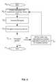
- FIG. 4is a flow diagram illustrating an exemplary wireless device calibration process, in accordance with an embodiment of the invention.
- Certain aspects of the inventionmay be found in a method and system for measuring and optimizing integrated antenna performance.
- Exemplary aspects of the inventionmay comprise transmitting FM radio signals over a range of frequencies utilizing one or more antenna configurations.
- the FM radio transmittermay be calibrated based on a signal received by the wireless device via one of the plurality of receivers that utilizes the other wireless protocols.
- the wireless devicemay include one or more other corresponding transmitters that utilize other wireless protocols.
- the transmitted FM radio signalsmay be received by a test set comprising an FM radio receiver and one or more other corresponding transmitters that utilize other wireless protocols.
- the signal received at the wireless device via one of the one or more receiversis generated at the test set via the one or more corresponding transmitters that utilize other wireless protocols.
- the frequency of the transmitted FM radio signalsmay be varied over at least a portion of the range of frequencies utilizing a tunable oscillator, and the one or more antenna configurations may be varied, based on the variation of the frequency of the transmitted FM radio signals.
- the antenna configurationsmay be impedance matched to the FM radio transmitter over the range of frequency of the transmitted FM radio signals by adjusting a capacitive and/or inductive load.
- the FM radio transmitter, FM radio receiver and the tunable oscillatormay be integrated within a single chip.
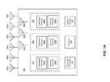
- FIG. 1Ais a block diagram of an exemplary system that enables multi-protocol communication, in accordance with an embodiment of the invention.
- a mobile terminal 150comprising a plurality of transceivers 151 , 152 , and 153 , a baseband processor 154 , a processor 156 , external antennas 160 a - f , internal antennas 162 a - c and system memory 158 .
- the transceivers 151 , 152 , and 153may each comprise a transmitter front end 151 a , 152 a , 153 a , respectively, and a receiver front end 151 b , 152 b , 153 b , respectively.
- the transmitter front ends 151 a , 152 a , and 153 amay comprise suitable circuitry, logic, and/or code that may be adapted to process and transmit RF signals.
- the transmitter and receiver front ends for each wireless protocolmay be integrated on a single chip.
- each of the transceiversmay be integrated on a single chip.
- the external antennas 160 a - f and the internal antennas 162 a - cmay comprise antennas that may be used for different wireless protocols, such as Bluetooth, NFC, WLAN and FM, for example.
- the internal antennas 162 a - cmay each comprise any metal component within the wireless communication device that may act as an antenna.
- One or more of the antennasmay be selected to transmit and/or receive wireless signals.
- a plurality of combinations of selected antennasmay be switched on, and received signals may be measured and compared to assess the optimum antenna configuration at a particular frequency.
- the transmitter front ends 151 a , 152 a , and 153 amay receive baseband signals communicated by a baseband processor, such as, for example, the baseband processor 154 .
- the signalsmay then be, for example, filtered, amplified, upconverted, and/or modulated for transmission.
- the baseband signalmay be analog or digital depending on the functionality of the transmitter front end 151 a , 152 a , or 153 a and the baseband processor 154 .
- the receiver front ends 151 b , 152 b , and 153 bmay comprise suitable circuitry, logic, and/or code that may be adapted to receive and process RF signals.
- the receiver front ends 151 b , 152 b , and 153 bmay amplify, filter, down-convert, and/or demodulate the received signals to generate a baseband signal.
- the baseband signalmay be analog or digital depending on the functionality of the receiver front end 151 b , 152 b , or 153 b and the baseband processor 154 .
- the baseband processor 154is depicted as a single block for the sake of simplicity, however, the invention need not be so limited.
- other embodiments of the inventionmay comprise a plurality of baseband processors for processing signals to and/or from the transceivers 151 , 152 , and 153 .
- the baseband processor 154may comprise suitable circuitry, logic, and/or code that may be adapted to process received baseband signals from the receiver front ends 151 b , 152 b , and 153 b .
- the baseband processor 154also may comprise suitable logic, circuitry, and/or code that may be adapted to process a baseband signal for communication to the transmitter front ends 151 a , 152 a , and 153 a.
- the processor 156may comprise suitable logic, circuitry, and/or code that may be adapted to control the operations of the transceivers 151 , 152 , and 153 and/or the baseband processor 154 .
- the processor 156may be utilized to update and/or modify programmable parameters and/or values in a plurality of components, devices, and/or processing elements in the transceivers 151 , 152 , and 153 and/or the baseband processor 154 .
- Control and/or data informationmay also be transferred to and/or from another controller and/or processor in the mobile terminal 150 to the processor 156 .
- the processor 156may transfer control and/or data information to another controller and/or processor in the mobile terminal 150 .
- the processor 156may utilize the received control and/or data information to determine a mode of operation for the transceivers 151 , 152 , and/or 153 .
- the processor 156may control each of the receiver front ends 151 b , 152 b , and 153 b to receive RF signals at a specific frequency.
- the processor 156may control each of the transmitter front ends 151 a , 152 a , and 153 a to transmit RF signals at a specific frequency.
- the processor 156may also adjust a specific gain for a variable gain amplifier, and/or adjust filtering characteristics for a filter.
- a specific frequency selected and/or parameters needed to calculate the specific frequency, and/or the specific gain value and/or the parameters needed to calculate the specific gainmay be stored in the system memory 158 via the processor 156 .
- This information stored in system memory 158may be transferred to the receiver front end 152 from the system memory 158 via the processor 156 .
- the system memory 158may comprise suitable circuitry, logic, and/or code that may be adapted to store a plurality of control and/or data information, including parameters needed to calculate frequencies and/or gain, and/or the frequency value and/or gain value.
- the wireless protocols transmitted and received by the mobile terminal 150may comprise FM, WLAN, Bluetooth and near field communication (NFC), for example.
- the size of a systemsuch as a cellular phone with multi-protocol capability, may be greatly reduced if the radio functions for these protocols may be integrated onto a single chip.
- integrating a transmitter and a receiver for a particular wireless protocol on a single chipmay enable configuration, calibration and performance optimization of a transceiver.
- the calibration of FM antennasmay be difficult, due to loading effects. Any device that may be coupled to an FM transmitter may effect the tuning characteristics of the device.
- FIG. 1Bis a block diagram of an exemplary FM transmitter that communicates with handheld devices that utilize a single chip with an integrated multi-wireless protocol transmitter and receiver, in accordance with an embodiment of the invention.
- an FM transmitter 102there is shown an FM transmitter 102 , a cellular phone 104 a , a smart phone 104 b , a computer 104 c , and an exemplary multi-wireless protocol equipped device 104 d .
- the FM transmitter 102may be implemented as part of a radio station or other broadcasting device, for example.
- Each of the cellular phone 104 a , the smart phone 104 b , the computer 104 c , and the exemplary multi-wireless protocol equipped device 104 dmay comprise a single chip 106 a , 106 b , 106 c and 106 d with multi-protocol transmitters and receivers.
- the single chip 106may comprise FM and Bluetooth (BT) transmitters and receivers, although the invention is not so limited. Accordingly, any number of wireless protocol transmitters and receivers may be integrated on-chip, depending on system requirements and/or size of the chip die.
- the FM transmitter 102may enable communication of FM audio data to the devices shown in FIG.
- Each of the devices in FIG. 1Bmay comprise and/or may be communicatively coupled to a listening device 108 such as a speaker, a headset, or an earphone, for example.
- a listening device 108such as a speaker, a headset, or an earphone, for example.
- the cellular phone 104 amay be enabled to receive an FM transmission signal from the FM transmitter 102 . The user of the cellular phone 104 a may then listen to the transmission via the listening device 108 .
- the cellular phone 104 amay comprise a “one-touch” programming feature that enables pulling up specifically desired broadcasts, like weather, sports, stock quotes, or news, for example.
- the smart phone 104 bmay be enabled to receive an FM transmission signal from the FM transmitter 102 . The user of the smart phone 104 b may then listen to the transmission via the listening device 108 .
- the computer 104 cmay be a desktop, laptop, notebook, tablet, and/or a PDA, for example.
- the computer 104 cmay be enabled to receive an FM transmission signal from the FM transmitter 102 .
- the user of the computer 104 cmay then listen to the transmission via the listening device 108 .
- the computer 104 cmay comprise software menus that configure listening options and enable quick access to favorite options, for example.
- the computer 104 cmay utilize an atomic clock FM signal for precise timing applications, such as scientific applications, for example. While a cellular phone, a smart phone, computing devices, and other devices are shown in FIG. 1B , the single chip 106 may be utilized in a plurality of other devices and/or systems that receive and use multiple wireless protocols such as Bluetooth, NFC, WLAN, RFID and FM signals, for example.
- FIG. 1Cis a block diagram of an exemplary FM receiver that communicates with handheld devices that utilize a single chip with an integrated multi-wireless protocol transmitter and receiver in accordance with an embodiment of the invention.
- an FM receiver 110there is shown an FM receiver 110 , the cellular phone 104 a , the smart phone 104 b , the computer 104 c , and the exemplary multi-wireless protocol equipped device 104 d .
- the FM receiver 110may comprise and/or may be communicatively coupled to a listening device 108 .
- a device equipped with the an integrated FM transmitter and FM receiversuch as the single chip 106 a , 106 b , 106 c or 106 d , may be able to transmit or broadcast its respective signal to a “deadband” of an FM receiver for use by the associated audio system.
- a cellphone or a smart phonesuch as the cellular phone 104 a and the smart phone 104 b , may transmit a telephone call for listening over the audio system of an automobile, which may comprise the FM receiver 110 and the speakers 108 , via usage of a deadband area of the car's FM stereo system. This may provide a universal capability to use this feature with all automobiles equipped simply with an FM radio with few, if any, other external FM transmission devices or connections being required.
- a computersuch as the computer 104 c
- the music on the computer 104 cmay then be listened to on a standard FM receiver, such as the FM receiver 110 , with few, if any, other external FM transmission devices or connections.
- a cellular phone 104 a , a smart phone 104 b , and computing device 106 care shown, a single chip that combines an FM transmitter and an FM receiver may be utilized in a plurality of other devices and/or systems that receive and use an FM signal.
- the antennas for the FM transmitter and receivermay require calibration for optimum signal strength and accurate channel selection. Due to the high sensitivity of FM antennas to coupled electronics and/or wiring, or even proximity to metal equipment, it is desirable to incorporate calibration capability within the wireless device. In addition, due to the wide variation in wireless device size and component layout within the device, an FM transmitter/receiver may be configured to be configurable for a wide array of antennas.
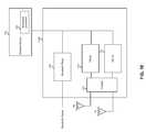
- FIG. 1Dis a block diagram of an exemplary single chip with integrated Bluetooth and FM Tx and FM Rx that supports FM processing and an external device that supports Bluetooth processing, in accordance with an embodiment of the invention.
- a single chip 112 athat supports Bluetooth and FM Tx and Fm Rx operations and an external device 114 .
- the single chip 112 amay comprise an integrated Bluetooth radio 116 , an integrated FM Rx 118 , an integrated processor 120 , a coupler 123 and an FM transmitter (Tx) 121 .
- the Bluetooth radio 116may comprise suitable logic, circuitry, and/or code that enable Bluetooth signal communication via the single chip 112 a .
- the Bluetooth radio 116may support processing, playback and communication of audio signals.
- the FM radiomay comprise suitable logic, circuitry, and/or code that enable FM signal communication via the single chip 112 a.
- the integrated processor 120may comprise suitable logic, circuitry, and/or code that may enable processing of the FM data received by the FM Rx 118 . Moreover, the integrated processor 120 may enable processing of FM data to be transmitted by the FM Rx 118 when the FM Rx 118 comprises transmission capabilities.
- the external device 114may comprise a baseband processor 122 .
- the baseband processor 122may comprise suitable logic, circuitry, and/or code that may enable processing of Bluetooth data received by the Bluetooth radio 116 .
- the baseband processor 122may enable processing of Bluetooth data to be transmitted by the Bluetooth radio 116 .
- the Bluetooth radio 116may communicate with the baseband processor 122 via the external device 114 .
- the Bluetooth radio 116may communicate with the integrated processor 120 .
- the FM transmitter 121may comprise suitable logic, circuitry, and/or that may enable transmission of FM signals via appropriate broadcast channels, for example.
- the coupler 123may comprise suitable circuitry, logic and/or code for coupling the Rx and Tx antennas to the FM Rx 118 and the FM Tx 121 . In this manner, each, or both antennae may be utilized to transmit and/or receive FM signals. An externally measured maximum transmit signal swept over the desired frequency of operation may be utilized to determine an optimum antenna configuration.
- FIG. 1Eis a block diagram of an exemplary single chip with integrated Bluetooth and FM radios and an external device that supports Bluetooth and FM processing, in accordance with an embodiment of the invention.
- a single chip 112 bthat supports Bluetooth and FM radio operations and an external device 114 .
- the single chip 112 bmay comprise the Bluetooth radio 116 , an FM Rx 118 , a couple 123 and an FM Tx 121 .
- the Bluetooth radio 116 and/or the FM Rx 118 and FM Tx 121may be integrated into the single chip 112 b .
- the external device 114may comprise a baseband processor 122 .
- the baseband processor 122may comprise suitable logic, circuitry, and/or code that may enable processing of Bluetooth data received by the Bluetooth radio 116 and/or processing of Bluetooth data to be transmitted by the Bluetooth radio 116 .
- the Bluetooth radio 116may communicate with the baseband processor 122 via the external device 114 .
- the baseband processor 122may comprise suitable logic, circuitry, and/or code that may enable processing of the FM data received by the FM Rx 118 .
- the baseband processor 122may enable processing FM data to be transmitted by the FM Tx 121 .
- the FM Rx 118 and FM Tx 121may communicate with the baseband processor 122 via the external device 114 .
- the couplermay be substantially similar to the coupler 123 described with respect to FIG.
- An optimum configurationmay be determined by measuring a maximum transmit signal strength and receiving a feedback via another wireless protocol, such as Bluetooth, for example, to tune and calibrate the FM Tx 121 .
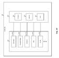
- FIG. 1Fis a block diagram of an exemplary single chip with multiple integrated radios that supports radio data processing, in accordance with an embodiment of the invention.
- a single chip 130may comprise a radio portion 132 and a processing portion 134 .
- the radio portion 132may comprise a plurality of integrated radios.
- the radio portion 132may comprise a cell radio 140 a that supports cellular communications, a Bluetooth radio 140 b that supports Bluetooth communications, an FM receive and transmit (Rx/Tx) radio 140 c that supports FM communications, a global positioning system (GPS) 140 d that supports GPS communications, and/or a wireless local area network (WLAN) 140 e that supports communications based on the IEEE 802.11 standards.
- GPSglobal positioning system
- WLANwireless local area network
- the processing portion 134may comprise at least one processor 136 , a memory 138 , and a peripheral transport unit (PTU) 140 .
- the processor 136may comprise suitable logic, circuitry, and/or code that enable processing of data received from the radio portion 132 .
- each of the integrated radiosmay communicate with the processing portion 134 .
- the integrated radiosmay communicate with the processing portion 134 via a common bus, for example.
- the memory 138may comprise suitable logic, circuitry, and/or code that enable storage of data that may be utilized by the processor 136 .
- the memory 138may store at least a portion of the data received by at least one of the integrated radios in the radio portion 132 .
- the memory 138may store at least a portion of the data that may be transmitted by at least one of the integrated radios in the radio portion 132 .
- the PTU 140may comprise suitable logic, circuitry, and/or code that may enable interfacing data in the single chip 130 with other devices that may be communicatively coupled to the single chip 130 .
- the PTU 140may support analog and/or digital interfaces.
- an optimum antenna configurationmay be determined by sweeping the frequency of a transmission signal utilizing a plurality of antenna configurations, measuring the transmitted signal utilizing an external test set, and feeding back a signal via a different wireless protocol that may enable calibration and/or tuning of the FM Rx/Tx 140 c.
- FIG. 2is a block diagram of an exemplary system for FM transmission and reception, in accordance with an embodiment of the invention.
- the radio 200may comprise two frequency synthesizers 224 a and 224 b , an FM receive (Rx) block 226 , a memory 228 , a processor 230 , a switch network/coupler 234 , an antenna block 236 and an FM transmit (Tx) block 232 .
- RxFM receive
- TxFM transmit
- the frequency synthesizers 224 a and 224 bmay comprise suitable circuitry, logic, and/or code that may enable generation of fixed or variable frequency signals.
- the frequency synthesizers 224 a and 224 bmay each comprise one or more direct digital frequency synthesizers, along with a clock source, such as a Bluetooth or RFID phase-locked loop (PLL) clock generator.
- a clock sourcesuch as a Bluetooth or RFID phase-locked loop (PLL) clock generator.
- the memory 228may comprise suitable circuitry, logic, and/or code that may enable storing information.
- the memory 228may, for example, enable storing information utilized for controlling and/or configuring the frequency synthesizers 224 a and 224 b .
- the memory 228may store the value of state variables that may be utilized to control the frequency output by each of the frequency synthesizers 224 a and 224 b .
- the memory 228may enable storing information that may be utilized to configure the FM Rx block 226 and the FM Tx block 232 .
- the FM Rx block 226 and/or the FM Tx block 232may comprise circuitry, logic, and/or code such as a filter, for example, that may be configured based on the desired frequency of operation.
- the processor 230may comprise suitable circuitry, logic, and/or code that may enable interfacing to the memory 228 , the frequency synthesizers 224 a and 224 b , the FM Rx block 226 and/or the FM Tx block 232 .
- the processor 230may be enabled to execute one or more instructions that enable reading and/or writing to/from the memory 228 .
- the processor 230may be enabled to execute one or more instructions that enable providing one or more control signals to the frequency synthesizer 224 , the FM Rx block 226 , and/or the FM Tx block 232 .
- the FM Rx block 226may comprise suitable circuitry, logic, and/or code that may enable reception of FM signals.
- the FM Rx block 226may be enabled to tune to a desired channel, amplify received signals, down-convert received signals, and/or demodulate received signals to, for example, output data and/or audio information comprising the channel.
- the FM Rx block 226may utilize in-phase and quadrature local oscillator signals generated by the frequency synthesizer 224 a to down-convert received FM signals.
- the FM Rx block 226may, for example, be enabled to operate over the “FM broadcast band”, or approximately 76 MHz to 108 Mhz. Signal processing performed by the FM Rx block 226 may be performed in the analog domain or the digital domain.
- the FM Rx block 226may comprise one or more analog to digital converters (ADCs) and/or digital to analog converters (DACs) which may enable processing in the analog and/or digital domain.
- ADCsanalog to digital converters
- the FM Tx block 232may comprise suitable circuitry, logic, and/or code that may enable transmission of FM signals.
- the FM Tx block 232may enable frequency modulation of a carrier signal with audio/data information.
- the carrier frequencymay be generated by the clock frequency synthesizer 224 b .
- the FM Tx block 232may also enable up-converting a modulated signal to a frequency, for example, in the “FM broadcast band”, or approximately 76 MHz to 108 Mhz. Additionally, the FM Tx block 232 may enable buffering and/or amplifying a FM signal such that the signal may be transmitted via an antenna.
- the frequency synthesizer 224 amay comprise a DDFS that may be capable of providing FM modulation for the signal to be transmitted.
- the switch network/coupler 234may comprise suitable circuitry, logic and or code that may enable coupling the FM Tx block 232 and the FM Rx block 226 to the antenna block 236 for the transmission and reception of wireless signals.
- the antenna block 236may comprise a plurality of antennas.
- the switch network/coupler 234may couple the FM Tx block 232 and the FM Rx block 226 to the plurality of antennas.
- the plurality of antennasmay comprise internal and externally coupled antennas, or even various metal components within the housing which may contain the radio 200 or even metal components of the housing itself.
- one or more signals provided by the processor 230may configure the system 200 to transmit and/or receive FM signals.
- the processor 230may provide one or more control signals to frequency synthesizers 224 a and 224 b in order to generate appropriate LO frequencies based on the reference signal f ref .
- the processormay interface to the memory 228 in order to determine the appropriate state of any control signals provided to the frequency synthesizers 224 a and 224 b .
- the transmit frequency and receive frequencymay be determined independently. Accordingly, utilizing a transmit frequency different from the receive frequency may enable simultaneous transmission and reception of FM signals.
- the FM Tx block 232may be calibrated by sweeping the output frequency of the frequency synthesizer 224 b over the entire range, and measuring the output signal via an external test system described further with respect to FIG. 4 .
- the configuration of the FM Tx block 232may be adjusted, such as through impedance matching, for example, also described further with respect to FIG. 4 . In this manner, the FM Tx block 232 may be calibrated without coupling test equipment or circuitry to the FM Tx block 232 , which may affect the performance of the device, skewing the calibration results.
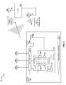
- FIG. 3is a block diagram illustrating an exemplary wireless device antenna calibration system, in accordance with an embodiment of the invention.
- a wireless antenna configuration system 300comprising a wireless device 301 and a test set 325 .
- the wireless device 301may comprise external antennas 303 A, 303 B and 303 C, internal antennas 305 A and 305 B, a switch network 307 , a transmit/receive (Tx/Rx) chip 309 , a T/R switch 313 and an internal metal component 311 .
- Tx/Rxtransmit/receive
- the Tx/Rx chip 309may comprise on-chip impedance matching blocks 315 A and 315 B, an FM transmit (Tx) block 317 , a voltage-controlled oscillator (VCO) 321 , a Bluetooth (BT) Tx/Rx block 323 and an FM receive (Rx) block 319 .
- the test set 325may comprise an FM antenna 327 A and a Bluetooth (BT) antenna 327 B.
- the external antennas 303 A, 303 B and 303 Cmay comprise externally coupled antennas that each may be enabled for transmitting and receiving a signal conforming to a particular wireless protocol, such as Bluetooth, WLAN, RFID, and/or FM, for example.
- the internal antennas 305 A and 305 Bmay similarly be enabled for transmitting and receiving a signal conforming to a particular wireless protocol, and may be located internal to the case enclosing the wireless device 301 .
- the internal metal component 311may comprise a metal component located within and/or part of the wireless device enclosure, which when coupled to one or more of the antennas may alter the transmit/receive characteristics, such as transmitted and/or received power, for example, of the coupled one or more antennas.
- the number of antennas or internal metal componentsmay not be limited to the number shown in FIG. 3 . Accordingly, the wireless device 301 may comprise any number of antennas as well as any internal metal components that may affect the Tx/Rx characteristics of the system.
- the internal metal component 311 or componentsmay be utilized in instances where the transmit/receive characteristics may be improved, such as in the transmission and/or reception of FM signals where the increased size of the antenna may increase signal strength.
- the switch network 307may comprise suitable circuitry, logic and/or code that may enable selection of one or more of the antennas and metal components that may be utilized to transmit and receive FM signals.
- the switch networkmay be controlled by a processor, such as the processor 230 , described with respect to FIG. 2 .
- the switch network 307may couple one or more of the antennas comprising the external antennas 303 A, 303 B, 303 C, and/or one or more of the internal antennas 305 A and 305 B, as well as one or more metal components, such as the internal metal component 311 to the T/R switch 313 and/or to the BT Tx/Rx block 323 .
- the internal and external antennas and internal metal component or componentsmay be connected in series or parallel to obtain multiple antenna configurations.
- the Tx/Rx chip 309may comprise suitable circuitry, logic and/or code that may enable transmission and reception of multiple wireless protocol signals.
- the Tx/Rx chip 309may comprise FM and BT transmitters and receivers, although the invention need not be so limited. Accordingly, any number of wireless protocol transmitters and receivers may be integrated on-chip, depending on system requirements and/or size of the chip die.
- the FM Tx block 317may comprise suitable circuitry, logic and/or code that may enable transmission of FM signals via the T/R switch 313 , the switch network 307 and selected one or more of the external antennas 303 A, 303 B, 303 C, and/or one or more of the internal antennas 305 A and 305 B.
- the FM Rx block 319may comprise suitable circuitry, logic and/or code that may enable reception of FM signals over the same selected antennas.
- the switch network 307may be configured to couple the BT Tx/Rx block 323 to one or more appropriate antennas for transmission and/or reception of Bluetooth signals.
- the T/R switch 313may comprise suitable circuitry, logic and/or code that may enable switching of the selected antenna configuration to be coupled with the FM Tx block 317 and/or the FM Rx block 319 .
- the T/R switchmay be enabled to couple both the FM Tx block 317 and the FM Rx block 319 to the selected antenna configuration.
- the VCO 321may comprise suitable circuitry, logic and/or code that may enable generation of a variable frequency output signal that may be utilized by the FM Tx block 317 and the FM Rx block 319 for transmission and reception of FM signals, respectively.
- the frequency of the output signalmay be a function of an input voltage, and may be controlled via a processor, such as the processor 230 , described with respect to FIG. 2 .
- the VCO 321may be utilized to clock one or more direct digital frequency synthesizers (DDFSs).
- DDFSsdirect digital frequency synthes
- the test set 325may comprise suitable circuitry, logic and/or code that may be enabled for reception of wireless signals to measure various characteristics of the transmission, such as frequency, signal strength and bandwidth, for example.
- the test set 325may be a calibrated system capable of determining FM radio frequency channels according to appropriate standards applicable to the wireless device 301 .
- the test set 325may comprise the antenna 327 A, which may be enabled to receive the FM signals transmitted by a wireless device, such as the wireless device 301 .
- the test set 325may also comprise the antenna 327 B, which may be enabled to transmit and/or receive Bluetooth signals that may be utilized by the wireless device 301 for configuration of the Tx/Rx chip 309 and/or the switch network 307 .
- the configurationmay comprise calibration of the VCO 321 , adjustment of the impedance matching, or selection of optimum antenna configuration, for example.
- the FM Tx block 317may be coupled to selected antennas via the T/R switch 313 and the switch network 307 .
- the VCO 321may be enabled to sweep the frequency of FM transmission via the selected antenna or antennas.
- the transmitted signalmay be received by the test set 325 via the antenna 327 A.
- the test set 325may be utilized to calibrate the frequency of the FM channels transmitted by the FM Tx block 317 .
- the FM Tx block 317may be enabled to generate an FM signal to be transmitted by the internal and/or external antennas selected by the switch network 307 .
- the on-chip impedance matching block 315 Amay be enabled to match the output impedance of the FM Tx 317 to the antennas selected by the switch network 307 .
- the T/R switch 313may be configured for transmit mode operation, and an impedance within the T/R switch 313 in conjunction with the on-chip impedance match block 315 A may also provide impedance match to the antennas selected by the switch network 307 .
- the output frequency of the VCO 321may be swept across the entire FM frequency range, 70-120 MHz, for example.
- the test set 325may be enabled to receive the transmitted FM signal, and to determine characteristics of the signal that may be utilized to optimize the performance of the Tx/Rx chip 309 .
- the test set 325may also be enabled to transmit data utilizing a different wireless protocol, such as Bluetooth, for example, via the antenna 327 B.
- the test set 325may determine the frequency of the FM signal transmitted by the wireless device 301 and may transmit data to the wireless device that may indicate that the VCO 321 frequency may need adjustment, or the impedance matching of the FM Tx 317 to the selected antennas may need to be adjusted.
- the wireless protocol over which the wireless device 301 may receive adjustment parametersmay not be limited to Bluetooth. Accordingly, any wireless protocol integrated in the wireless device 301 , such as WLAN, RFID and/or near field communication (NFC), for example, may be utilized.
- the signal strength of the FM signal transmitted by the wireless device 301may be increased by appropriate selection of antennas, such as the external antennas 303 A-C, the internal antennas 305 A and 305 B, or internal metal components, such as the internal metal component 311 .
- the calibrated transmitter antenna configurationmay also define the calibrated receiver antenna configuration for the FM Rx block 319 .
- the optimum antenna configurationmay change with variations in wireless device 301 design, for example, the integration of the calibration capability may be performed within the Tx/Rx chip 309 , as opposed to using externally coupled test fixtures.
- the plurality of antennasmay be utilized to tune the antenna characteristics to a particular frequency range. For example, if two antennas are optimized for 108 MHz and when they may be coupled together, they may be optimized for 76 MHz. They may form a duo band antenna, and by the combination of the two, the range of the antenna may be extended. Since the FM band may comprise a large range, nearly an octave, an antenna may be tuned for the highest frequencies, and then combined with the other antenna to result in another size antenna for a different frequency range.
- the wireless protocols integrated in the Tx/Rx chip 309 utilized for impedance matching, antenna configuration, and frequency calibrationare not limited to FM.
- any wireless protocol transmitter and receiver integrated in the Tx/Rx chip 309may be utilized to transmit signals to and receive signals from the test set 325 .
- FIG. 4is a flow diagram illustrating an exemplary wireless device calibration process, in accordance with an embodiment of the invention.
- the antenna or antennas of the wireless device 301may be coupled to the FM Tx 317 block 317 via the switch network 307 , the T/R switch 313 and the on-chip impedance matching block 315 A.
- the frequency of the VCO 321may be swept across the frequency range of interest, 70-120 MHz, for example, for the FM broadcast spectrum.
- the FM signal generated by the FM Tx block 317may be transmitted by one or more of the antennas 303 A-C, 305 A, 305 B, and one or more internal metal components such as the internal metal component 311 .
- the test set 325may receive the transmitted FM signal via the antenna 327 A.
- the test set 325may determine signal characteristics of the received signal, such as frequency, bandwidth and/or signal strength, for example. If the test set 325 may determine that the calibration and/or optimization of the FM transmission may not be complete, the test set 325 may transmit adjustment parameters utilizing the Bluetooth wireless protocol to the wireless device 301 in step 411 , and jump back to step 403 to again sweep the VCO 321 frequency. If the test set 325 may determine that the calibration and/or optimization may be complete, the process may step to end step 413 .
- a method and systemfor measuring and optimizing integrated antenna performance and may comprise enabling one or more antennas 303 A-C, 305 A, 305 B and 311 and impedance matching circuits 315 A, 315 B and 313 , varying a frequency of an FM transmitter 317 on a chip 309 while transmitting to an external test set 325 utilizing an oscillator 321 integrated on the chip 309 .
- the FM transmitter 317may be adjusted via a signal received from the external test set 325 via a different wireless protocol.
- the adjustingmay comprise selecting and/or deselecting one or more of the antennas 303 A-C, 305 A, 305 B and 311 or reconfiguring the impedance matching circuits 315 A, 315 B and 313 .
- the reconfiguringmay comprise selecting one or more capacitors or inductors.
- the antennasmay be internal or external to the wireless device 301 , and may be designed for multiple wireless protocols.
- the antennasmay also comprise metal components 311 within and/or part of an enclosure of the wireless device 301 .
- the tunable oscillator 321may comprise a voltage controlled oscillator or a direct digital frequency synthesizer.
- a method and systemare disclosed for transmitting FM radio signals over a range of frequencies utilizing one or more antenna configurations.
- the FM radio transmitter 317may be calibrated based on a signal received by the wireless device 301 via one of the plurality of receivers that utilizes the other wireless protocols.
- the other wireless protocolsmay comprise Bluetooth, WiFi, near-field communication (NFC) and RFID, for example.
- the wireless device 301may include one or more other corresponding transmitters 323 that utilize other wireless protocols.
- the transmitted FM radio signalsmay be received by a test set comprising an FM radio receiver 319 and one or more other corresponding transmitters 323 that utilize other wireless protocols.
- the signal received at the wireless device 301 via one of the one or more other receivers 323is generated at the test set 325 via the one or more corresponding transmitters that utilize other wireless protocols.
- the frequency of the transmitted FM radio signalsmay be varied over at least a portion of the range of frequencies utilizing a tunable oscillator 321 , and the one or more antenna configurations may be varied, based on the variation of the frequency of the transmitted FM radio signals.
- the antenna configurationsmay be impedance matched to the FM radio transmitter 317 over the range of frequency of the transmitted FM radio signals by adjusting a capacitive and/or inductive load.
- the FM radio transmitter 317 , FM radio receiver 319 and the tunable oscillator 321may be integrated within a single chip 309 .
- Certain embodiments of the inventionmay comprise a machine-readable storage having stored thereon, a computer program having at least one code section for communicating information within a network, the at least one code section being executable by a machine for causing the machine to perform one or more of the steps described herein.
- aspects of the inventionmay be realized in hardware, software, firmware or a combination thereof.
- the inventionmay be realized in a centralized fashion in at least one computer system or in a distributed fashion where different elements are spread across several interconnected computer systems. Any kind of computer system or other apparatus adapted for carrying out the methods described herein is suited.
- a typical combination of hardware, software and firmwaremay be a general-purpose computer system with a computer program that, when being loaded and executed, controls the computer system such that it carries out the methods described herein.
- One embodiment of the present inventionmay be implemented as a board level product, as a single chip, application specific integrated circuit (ASIC), or with varying levels integrated on a single chip with other portions of the system as separate components.
- the degree of integration of the systemwill primarily be determined by speed and cost considerations. Because of the sophisticated nature of modern processors, it is possible to utilize a commercially available processor, which may be implemented external to an ASIC implementation of the present system. Alternatively, if the processor is available as an ASIC core or logic block, then the commercially available processor may be implemented as part of an ASIC device with various functions implemented as firmware.
- the present inventionmay also be embedded in a computer program product, which comprises all the features enabling the implementation of the methods described herein, and which when loaded in a computer system is able to carry out these methods.
- Computer program in the present contextmay mean, for example, any expression, in any language, code or notation, of a set of instructions intended to cause a system having an information processing capability to perform a particular function either directly or after either or both of the following: a) conversion to another language, code or notation; b) reproduction in a different material form.
- other meanings of computer programwithin the understanding of those skilled in the art are also contemplated by the present invention.
Landscapes
- Transmitters (AREA)
- Transceivers (AREA)
- Stabilization Of Oscillater, Synchronisation, Frequency Synthesizers (AREA)
Abstract
Description
- U.S. patent application Ser. No. 11/832,598 filed on even date herewith;
- U.S. patent application Ser. No. 11/832,590 filed on even date herewith;
- U.S. patent application Ser. No. 11/832,468 filed on even date herewith; and
- U.S. patent application Ser. No. 11/832,488 filed on even date herewith.
Claims (23)
Priority Applications (1)
| Application Number | Priority Date | Filing Date | Title |
|---|---|---|---|
| US12/837,102US8391810B2 (en) | 2007-03-19 | 2010-07-15 | Method and system for measuring and optimizing integrated antenna performance |
Applications Claiming Priority (3)
| Application Number | Priority Date | Filing Date | Title |
|---|---|---|---|
| US89566507P | 2007-03-19 | 2007-03-19 | |
| US11/832,609US7792502B2 (en) | 2007-03-19 | 2007-08-01 | Method and system for measuring and optimizing integrated antenna performance |
| US12/837,102US8391810B2 (en) | 2007-03-19 | 2010-07-15 | Method and system for measuring and optimizing integrated antenna performance |
Related Parent Applications (1)
| Application Number | Title | Priority Date | Filing Date |
|---|---|---|---|
| US11/832,609ContinuationUS7792502B2 (en) | 2007-03-19 | 2007-08-01 | Method and system for measuring and optimizing integrated antenna performance |
Publications (2)
| Publication Number | Publication Date |
|---|---|
| US20100279633A1 US20100279633A1 (en) | 2010-11-04 |
| US8391810B2true US8391810B2 (en) | 2013-03-05 |
Family
ID=39774089
Family Applications (19)
| Application Number | Title | Priority Date | Filing Date |
|---|---|---|---|
| US11/781,787AbandonedUS20080233869A1 (en) | 2007-03-19 | 2007-07-23 | Method and system for a single-chip fm tuning system for transmit and receive antennas |
| US11/831,399Expired - Fee RelatedUS7586378B2 (en) | 2007-03-19 | 2007-07-31 | Method and system for using a frequency locked loop logen in oscillator systems |
| US11/832,598Expired - Fee RelatedUS7917115B2 (en) | 2007-03-19 | 2007-08-01 | Method and system for auto detecting and auto switching antennas in a multi-antenna FM transmit/receive system |
| US11/832,488AbandonedUS20080233911A1 (en) | 2007-03-19 | 2007-08-01 | Method and system for utilizing a power source as an fm antenna for an integrated fm radio |
| US11/832,498AbandonedUS20080232447A1 (en) | 2007-03-19 | 2007-08-01 | Method and system for calibration in an fm transceiver system |
| US11/832,468Expired - Fee RelatedUS7925220B2 (en) | 2007-03-19 | 2007-08-01 | Method and system for matching an integrated FM system to an antenna utilizing on-chip measurement of reflected signals |
| US11/832,590Active2029-09-20US8208886B2 (en) | 2007-03-19 | 2007-08-01 | Method and system for optimizing an FM transmitter and FM receiver in a single chip FM transmitter and FM receiver system |
| US11/832,609Expired - Fee RelatedUS7792502B2 (en) | 2007-03-19 | 2007-08-01 | Method and system for measuring and optimizing integrated antenna performance |
| US11/832,858AbandonedUS20080233954A1 (en) | 2007-03-19 | 2007-08-02 | Method And System For Processing Results Derived From Detecting Channels Suitable For FM Transmission In An Integrated FM Transmit/Receive System |
| US11/832,844Expired - Fee RelatedUS8027641B2 (en) | 2007-03-19 | 2007-08-02 | Method and system for detecting channels suitable for FM transmission in an integrated FM transmit/receive system |
| US11/839,345AbandonedUS20080233900A1 (en) | 2007-03-19 | 2007-08-15 | Method and system for calibration in an fm transceiver system with off-chip control |
| US11/846,989AbandonedUS20080233907A1 (en) | 2007-03-19 | 2007-08-29 | Method And System For Determining Channel Spacing And Configuring An FM Transmitter |
| US11/853,705AbandonedUS20080232523A1 (en) | 2007-03-19 | 2007-09-11 | Method And System For Mixing A Plurality Of Audio Sources In An FM Transmitter |
| US11/855,217Active2029-12-09US7974590B2 (en) | 2007-03-19 | 2007-09-14 | Method and system for simultaneous signal transmission on multiple selected frequencies |
| US11/936,156Active2030-05-02US7983617B2 (en) | 2007-03-19 | 2007-11-07 | Method and system for transmitting multiple channels on FM bands |
| US12/837,102Expired - Fee RelatedUS8391810B2 (en) | 2007-03-19 | 2010-07-15 | Method and system for measuring and optimizing integrated antenna performance |
| US13/071,651AbandonedUS20110171916A1 (en) | 2007-03-19 | 2011-03-25 | Auto Detecting and Auto Switching Antennas in a Mutli-Antenna FM Transmit/Receive System |
| US13/080,316Expired - Fee RelatedUS8270907B2 (en) | 2007-03-19 | 2011-04-05 | Method and system for matching an integrated FM system to an antenna utilizing on-chip measurement of reflected signals |
| US13/176,664Expired - Fee RelatedUS8467745B2 (en) | 2007-03-19 | 2011-07-05 | Method and system for simultaneous signal transmission on multiple selected frequencies |
Family Applications Before (15)
| Application Number | Title | Priority Date | Filing Date |
|---|---|---|---|
| US11/781,787AbandonedUS20080233869A1 (en) | 2007-03-19 | 2007-07-23 | Method and system for a single-chip fm tuning system for transmit and receive antennas |
| US11/831,399Expired - Fee RelatedUS7586378B2 (en) | 2007-03-19 | 2007-07-31 | Method and system for using a frequency locked loop logen in oscillator systems |
| US11/832,598Expired - Fee RelatedUS7917115B2 (en) | 2007-03-19 | 2007-08-01 | Method and system for auto detecting and auto switching antennas in a multi-antenna FM transmit/receive system |
| US11/832,488AbandonedUS20080233911A1 (en) | 2007-03-19 | 2007-08-01 | Method and system for utilizing a power source as an fm antenna for an integrated fm radio |
| US11/832,498AbandonedUS20080232447A1 (en) | 2007-03-19 | 2007-08-01 | Method and system for calibration in an fm transceiver system |
| US11/832,468Expired - Fee RelatedUS7925220B2 (en) | 2007-03-19 | 2007-08-01 | Method and system for matching an integrated FM system to an antenna utilizing on-chip measurement of reflected signals |
| US11/832,590Active2029-09-20US8208886B2 (en) | 2007-03-19 | 2007-08-01 | Method and system for optimizing an FM transmitter and FM receiver in a single chip FM transmitter and FM receiver system |
| US11/832,609Expired - Fee RelatedUS7792502B2 (en) | 2007-03-19 | 2007-08-01 | Method and system for measuring and optimizing integrated antenna performance |
| US11/832,858AbandonedUS20080233954A1 (en) | 2007-03-19 | 2007-08-02 | Method And System For Processing Results Derived From Detecting Channels Suitable For FM Transmission In An Integrated FM Transmit/Receive System |
| US11/832,844Expired - Fee RelatedUS8027641B2 (en) | 2007-03-19 | 2007-08-02 | Method and system for detecting channels suitable for FM transmission in an integrated FM transmit/receive system |
| US11/839,345AbandonedUS20080233900A1 (en) | 2007-03-19 | 2007-08-15 | Method and system for calibration in an fm transceiver system with off-chip control |
| US11/846,989AbandonedUS20080233907A1 (en) | 2007-03-19 | 2007-08-29 | Method And System For Determining Channel Spacing And Configuring An FM Transmitter |
| US11/853,705AbandonedUS20080232523A1 (en) | 2007-03-19 | 2007-09-11 | Method And System For Mixing A Plurality Of Audio Sources In An FM Transmitter |
| US11/855,217Active2029-12-09US7974590B2 (en) | 2007-03-19 | 2007-09-14 | Method and system for simultaneous signal transmission on multiple selected frequencies |
| US11/936,156Active2030-05-02US7983617B2 (en) | 2007-03-19 | 2007-11-07 | Method and system for transmitting multiple channels on FM bands |
Family Applications After (3)
| Application Number | Title | Priority Date | Filing Date |
|---|---|---|---|
| US13/071,651AbandonedUS20110171916A1 (en) | 2007-03-19 | 2011-03-25 | Auto Detecting and Auto Switching Antennas in a Mutli-Antenna FM Transmit/Receive System |
| US13/080,316Expired - Fee RelatedUS8270907B2 (en) | 2007-03-19 | 2011-04-05 | Method and system for matching an integrated FM system to an antenna utilizing on-chip measurement of reflected signals |
| US13/176,664Expired - Fee RelatedUS8467745B2 (en) | 2007-03-19 | 2011-07-05 | Method and system for simultaneous signal transmission on multiple selected frequencies |
Country Status (1)
| Country | Link |
|---|---|
| US (19) | US20080233869A1 (en) |
Cited By (2)
| Publication number | Priority date | Publication date | Assignee | Title |
|---|---|---|---|---|
| US20140141728A1 (en)* | 2012-11-19 | 2014-05-22 | Ixia | Methods, systems, and computer readable media for detecting antenna port misconfigurations |
| US10316998B2 (en) | 2004-04-22 | 2019-06-11 | Swagelok Company | Conduit fitting subassembly and retaining tool |
Families Citing this family (276)
| Publication number | Priority date | Publication date | Assignee | Title |
|---|---|---|---|---|
| US8744384B2 (en) | 2000-07-20 | 2014-06-03 | Blackberry Limited | Tunable microwave devices with auto-adjusting matching circuit |
| US7750685B1 (en)* | 2005-03-17 | 2010-07-06 | Rf Micro Devices, Inc. | Frequency measurement based frequency locked loop synthesizer |
| US7932784B1 (en) | 2005-03-17 | 2011-04-26 | Rf Micro Devices, Inc. | Frequency and phase locked loop synthesizer |
| US9406444B2 (en) | 2005-11-14 | 2016-08-02 | Blackberry Limited | Thin film capacitors |
| US7711337B2 (en) | 2006-01-14 | 2010-05-04 | Paratek Microwave, Inc. | Adaptive impedance matching module (AIMM) control architectures |
| TWI292257B (en)* | 2006-03-09 | 2008-01-01 | Wistron Corp | Wireless communication module capable of switching an internal antenna module and an external antenna module |
| US7574187B2 (en)* | 2006-05-30 | 2009-08-11 | Sony Ericsson Mobile Communications Ab | Battery charger antenna, method and device incorporating the same |
| US7714676B2 (en) | 2006-11-08 | 2010-05-11 | Paratek Microwave, Inc. | Adaptive impedance matching apparatus, system and method |
| US7535312B2 (en) | 2006-11-08 | 2009-05-19 | Paratek Microwave, Inc. | Adaptive impedance matching apparatus, system and method with improved dynamic range |
| US8036308B2 (en)* | 2007-02-28 | 2011-10-11 | Broadcom Corporation | Method and system for a wideband polar transmitter |
| US20080233869A1 (en)* | 2007-03-19 | 2008-09-25 | Thomas Baker | Method and system for a single-chip fm tuning system for transmit and receive antennas |
| US7683851B2 (en)* | 2007-03-19 | 2010-03-23 | Broadcom Corporation | Method and system for using a single transformer for FM transmit and FM receive functions |
| US7917104B2 (en) | 2007-04-23 | 2011-03-29 | Paratek Microwave, Inc. | Techniques for improved adaptive impedance matching |
| US8213886B2 (en) | 2007-05-07 | 2012-07-03 | Paratek Microwave, Inc. | Hybrid techniques for antenna retuning utilizing transmit and receive power information |
| WO2008155595A1 (en)* | 2007-06-18 | 2008-12-24 | Nokia Corporation | Method and device for continuation of multimedia playback |
| US20100054746A1 (en) | 2007-07-24 | 2010-03-04 | Eric Raymond Logan | Multi-port accumulator for radio-over-fiber (RoF) wireless picocellular systems |
| US8942645B2 (en)* | 2010-09-30 | 2015-01-27 | Broadcom Corporation | Method and system for communication via subbands in a 60 GHZ distributed communication system |
| US8942647B2 (en)* | 2010-09-30 | 2015-01-27 | Broadcom Corporation | Method and system for antenna switching for 60 GHz distributed communication |
| JP5363490B2 (en)* | 2007-10-02 | 2013-12-11 | オープンピーク インコーポレイテッド | System and method for interprocessor communication |
| US8175459B2 (en) | 2007-10-12 | 2012-05-08 | Corning Cable Systems Llc | Hybrid wireless/wired RoF transponder and hybrid RoF communication system using same |
| US20090117857A1 (en)* | 2007-11-02 | 2009-05-07 | Broadcom Corporation | FM radio devices determining preferred inactive FM radio channel for communication |
| US20090122749A1 (en)* | 2007-11-13 | 2009-05-14 | Joonbum Byun | Method and apparatus for localizing AM/FM/XM radio advertisement |
| US7991363B2 (en) | 2007-11-14 | 2011-08-02 | Paratek Microwave, Inc. | Tuning matching circuits for transmitter and receiver bands as a function of transmitter metrics |
| US7941194B2 (en)* | 2007-11-16 | 2011-05-10 | Silicon Laboratories Inc. | Antenna co-location in portable devices for simultaneous receive and transmit |
| US8718561B2 (en) | 2007-11-20 | 2014-05-06 | Aruba Networks, Inc. | Method and apparatus for detecting and avoiding interference in a communications network |
| KR101397035B1 (en)* | 2007-11-30 | 2014-05-20 | 엘지전자 주식회사 | Terminal and method of supporting broadcasting technology therein |
| US20090238158A1 (en)* | 2008-03-20 | 2009-09-24 | Infineon Technologies Ag | Packet Fragment Adaptation for Improved Coexistence |
| US20090247101A1 (en)* | 2008-03-28 | 2009-10-01 | Ligang Zhang | Auto-detection of broadcast channel spacing |
| US8478218B2 (en)* | 2008-06-11 | 2013-07-02 | Quintic Holdings | Frequency modulation (FM) clear channel scanning system and method of using same |
| US20100009631A1 (en)* | 2008-06-12 | 2010-01-14 | Griffin Jr Paul P | Transmitting accessory utilizing power system transmission |
| US8315578B2 (en)* | 2008-07-15 | 2012-11-20 | Research In Motion Limited | Mobile wireless communications device with separate in-phase and quadrature power amplification |
| US8072285B2 (en) | 2008-09-24 | 2011-12-06 | Paratek Microwave, Inc. | Methods for tuning an adaptive impedance matching network with a look-up table |
| US20100105340A1 (en)* | 2008-10-29 | 2010-04-29 | Qualcomm Incorporated | Interface for wireless communication devices |
| US8285233B2 (en)* | 2008-12-18 | 2012-10-09 | Nokia Corporation | Method for displaying other stations now playing list |
| US8682261B2 (en)* | 2009-02-13 | 2014-03-25 | Qualcomm Incorporated | Antenna sharing for wirelessly powered devices |
| US8422588B2 (en)* | 2009-04-01 | 2013-04-16 | Intel Mobile Communications GmbH | Variable-size mixer for high gain range transmitter |
| US8270921B2 (en)* | 2009-04-27 | 2012-09-18 | Csr Technology Inc. | Systems and methods for tuning an antenna for a frequency modulation transceiver |
| US8326233B2 (en)* | 2009-05-11 | 2012-12-04 | Broadcom Corporation | Method and system for a configurable tuned MOS capacitor |
| US8295788B2 (en)* | 2009-06-09 | 2012-10-23 | Broadcom Corporation | Method and system for an N-phase transmitter utilizing a leaky wave antenna |
| DE102009033673B4 (en)* | 2009-07-17 | 2015-12-24 | Qualcomm Technologies, Inc. (N.D.Ges.D. Staates Delaware) | Adaptively tuned matching network with improved linear behavior |
| KR101086569B1 (en)* | 2009-08-13 | 2011-11-23 | 엘지이노텍 주식회사 | Impedance regulator of adaptive tuning antenna circuit |
| US8472888B2 (en)* | 2009-08-25 | 2013-06-25 | Research In Motion Rf, Inc. | Method and apparatus for calibrating a communication device |
| US9503017B1 (en) | 2009-09-29 | 2016-11-22 | Qorvo Us, Inc. | Infrastructure-grade integrated voltage controlled oscillator (VCO) with linear tuning characteristics and low phase noise |
| US9026062B2 (en) | 2009-10-10 | 2015-05-05 | Blackberry Limited | Method and apparatus for managing operations of a communication device |
| US8774743B2 (en)* | 2009-10-14 | 2014-07-08 | Blackberry Limited | Dynamic real-time calibration for antenna matching in a radio frequency receiver system |
| US8208884B2 (en)* | 2009-10-28 | 2012-06-26 | Silicon Laboratories Inc. | Method and system for FM tuner ground isolation when using ground signal line as FM antenna |
| CN102612813A (en)* | 2009-11-16 | 2012-07-25 | 诺基亚公司 | A processor, apparatus and associated methods |
| US8559383B2 (en)* | 2009-11-20 | 2013-10-15 | Nokia Corporation | Multiradio control |
| US8825037B2 (en) | 2009-12-22 | 2014-09-02 | Starkey Laboratories, Inc. | FM radio system for digital and analog communications for hearing assistance devices |
| US8421408B2 (en)* | 2010-01-23 | 2013-04-16 | Sotoudeh Hamedi-Hagh | Extended range wireless charging and powering system |
| US20110181408A1 (en)* | 2010-01-28 | 2011-07-28 | Paul Gailey Greenis | Public Tactical Message System |
| US8718576B2 (en)* | 2010-02-11 | 2014-05-06 | Mediatek Inc. | Radio frequency modulator and method thereof |
| US8954011B2 (en)* | 2010-02-19 | 2015-02-10 | Broadcom Corporation | Method and system for a wireless integrated test and measurement device |
| US8803631B2 (en) | 2010-03-22 | 2014-08-12 | Blackberry Limited | Method and apparatus for adapting a variable impedance network |
| US8442577B2 (en)* | 2010-03-30 | 2013-05-14 | Mediatek Inc. | Wireless communication apparatus with an antenna shared between a plurality of communication circuits |
| KR101637211B1 (en)* | 2010-04-12 | 2016-07-08 | 삼성전자 주식회사 | Portable terminal and method for operating of mimo antenna thereof |
| JP5901612B2 (en) | 2010-04-20 | 2016-04-13 | ブラックベリー リミテッド | Method and apparatus for managing interference in a communication device |
| US8238924B2 (en) | 2010-04-30 | 2012-08-07 | The United States Of America As Represented By The Secretary Of The Navy | Real-time optimization of allocation of resources |
| TWI504063B (en)* | 2010-06-02 | 2015-10-11 | Chiun Mai Comm Systems Inc | System and method for antenna switching |
| US8548408B2 (en) | 2010-06-11 | 2013-10-01 | Panasonic Automotive Systems Company Of America, Division Of Panasonic Corporation Of North America | Method and apparatus for utilizing modulation based audio correlation technique for maintaining dynamic FM station list in single tuner variant and assisting alternate frequency switching methodology in single tuner and dual tuner variants |
| CN103296367B (en) | 2010-07-29 | 2016-02-10 | 天工方案公司 | Electricity container is made to reduce coupling coefficient change |
| CN101924834B (en)* | 2010-08-17 | 2013-07-03 | 惠州Tcl移动通信有限公司 | Method for using handle rope of fixed wireless phone as FM antenna and fixed wireless phone |
| US8572304B2 (en)* | 2010-09-28 | 2013-10-29 | Wellala, Inc. | Systems and methods for configuring mobile devices for printing to wireless printers |
| DE102010043031A1 (en)* | 2010-10-28 | 2012-05-03 | Endress + Hauser Flowtec Ag | Field device e.g. sensor for e.g. level measuring device, has antenna that is connected to conductor attachment structure, so that radio signal corresponding to electromagnetic signal is received over conductor attachment structure |
| US9379454B2 (en) | 2010-11-08 | 2016-06-28 | Blackberry Limited | Method and apparatus for tuning antennas in a communication device |
| US8686736B2 (en) | 2010-11-23 | 2014-04-01 | Infineon Technologies Ag | System and method for testing a radio frequency integrated circuit |
| US8712340B2 (en) | 2011-02-18 | 2014-04-29 | Blackberry Limited | Method and apparatus for radio antenna frequency tuning |
| US8655286B2 (en) | 2011-02-25 | 2014-02-18 | Blackberry Limited | Method and apparatus for tuning a communication device |
| CN102118838B (en)* | 2011-03-21 | 2013-11-06 | 惠州Tcl移动通信有限公司 | Frequency modulation (FM) channel-searching method of mobile phone and mobile phone |
| US8515416B2 (en)* | 2011-04-29 | 2013-08-20 | Silicon Laboratories Inc | Performing testing in a radio device |
| US8811906B2 (en) | 2011-05-13 | 2014-08-19 | Sierra Wireless, Inc. | Apparatus and method for multi-signal interference-avoiding data transmission |
| WO2012156988A2 (en)* | 2011-05-13 | 2012-11-22 | Indian Institute Of Technology, Bombay | Low power analog fm transceiver for bio-telemetry applications |
| US8626083B2 (en) | 2011-05-16 | 2014-01-07 | Blackberry Limited | Method and apparatus for tuning a communication device |
| US8594584B2 (en) | 2011-05-16 | 2013-11-26 | Blackberry Limited | Method and apparatus for tuning a communication device |
| KR101828302B1 (en)* | 2011-06-24 | 2018-03-22 | 삼성전자 주식회사 | Providing Method For Radio Channel List And Portable Device supporting the same |
| EP2740221B1 (en) | 2011-08-05 | 2019-06-26 | BlackBerry Limited | Method and apparatus for band tuning in a communication device |
| US8676116B2 (en) | 2011-10-07 | 2014-03-18 | Blackberry Limited | Electronic device with NFC antenna adjacent display and related methods |
| US8660612B2 (en) | 2011-10-07 | 2014-02-25 | Blackberry Limited | Electronic device having an NFC antenna in a speaker compartment and related methods |
| US9197467B2 (en) | 2011-10-21 | 2015-11-24 | Itron, Inc. | Multiple protocol receiver |
| US20130099938A1 (en)* | 2011-10-21 | 2013-04-25 | Itron, Inc. | Software-defined communication unit |
| US8837640B2 (en) | 2011-10-21 | 2014-09-16 | Itron, Inc. | Multiple protocol receiver |
| US9292782B2 (en)* | 2011-10-26 | 2016-03-22 | Qualcomm Incorporated | Adaptive NFC transceivers |
| US9331723B2 (en) | 2011-11-14 | 2016-05-03 | Blackberry Limited | Perturbation-based dynamic measurement of antenna impedance in real-time |
| US8412167B1 (en) | 2011-12-08 | 2013-04-02 | Sprint Communications Company L.P. | Wireless communication system that selects and broadcasts FM media streams on a per-base station basis |
| US8627162B2 (en)* | 2011-12-12 | 2014-01-07 | International Business Machines Corporation | Iimplementing enhanced aperture function calibration for logic built in self test (LBIST) |
| TWI514675B (en)* | 2012-01-19 | 2015-12-21 | Wistron Neweb Corp | Antenna apparatus and antenna switch circuit |
| US20130257667A1 (en)* | 2012-03-30 | 2013-10-03 | Broadcom Corporation | Antenna Tuning |
| WO2013170226A1 (en)* | 2012-05-10 | 2013-11-14 | Eden Rock Communications, Llc | Method and system for auditing and correcting cellular antenna coverage patterns |
| US8648634B2 (en) | 2012-05-10 | 2014-02-11 | International Business Machines Corporation | Input jitter filter for a phase-locked loop (PLL) |
| US8948889B2 (en) | 2012-06-01 | 2015-02-03 | Blackberry Limited | Methods and apparatus for tuning circuit components of a communication device |
| US9859797B1 (en) | 2014-05-07 | 2018-01-02 | Energous Corporation | Synchronous rectifier design for wireless power receiver |
| US10148097B1 (en) | 2013-11-08 | 2018-12-04 | Energous Corporation | Systems and methods for using a predetermined number of communication channels of a wireless power transmitter to communicate with different wireless power receivers |
| US10230266B1 (en) | 2014-02-06 | 2019-03-12 | Energous Corporation | Wireless power receivers that communicate status data indicating wireless power transmission effectiveness with a transmitter using a built-in communications component of a mobile device, and methods of use thereof |
| US10211680B2 (en) | 2013-07-19 | 2019-02-19 | Energous Corporation | Method for 3 dimensional pocket-forming |
| US10186913B2 (en) | 2012-07-06 | 2019-01-22 | Energous Corporation | System and methods for pocket-forming based on constructive and destructive interferences to power one or more wireless power receivers using a wireless power transmitter including a plurality of antennas |
| US10211682B2 (en) | 2014-05-07 | 2019-02-19 | Energous Corporation | Systems and methods for controlling operation of a transmitter of a wireless power network based on user instructions received from an authenticated computing device powered or charged by a receiver of the wireless power network |
| US10270261B2 (en) | 2015-09-16 | 2019-04-23 | Energous Corporation | Systems and methods of object detection in wireless power charging systems |
| US10124754B1 (en) | 2013-07-19 | 2018-11-13 | Energous Corporation | Wireless charging and powering of electronic sensors in a vehicle |
| US10063106B2 (en) | 2014-05-23 | 2018-08-28 | Energous Corporation | System and method for a self-system analysis in a wireless power transmission network |
| US10206185B2 (en) | 2013-05-10 | 2019-02-12 | Energous Corporation | System and methods for wireless power transmission to an electronic device in accordance with user-defined restrictions |
| US9124125B2 (en) | 2013-05-10 | 2015-09-01 | Energous Corporation | Wireless power transmission with selective range |
| US9438045B1 (en) | 2013-05-10 | 2016-09-06 | Energous Corporation | Methods and systems for maximum power point transfer in receivers |
| US10038337B1 (en) | 2013-09-16 | 2018-07-31 | Energous Corporation | Wireless power supply for rescue devices |
| US9853458B1 (en) | 2014-05-07 | 2017-12-26 | Energous Corporation | Systems and methods for device and power receiver pairing |
| US10141768B2 (en) | 2013-06-03 | 2018-11-27 | Energous Corporation | Systems and methods for maximizing wireless power transfer efficiency by instructing a user to change a receiver device's position |
| US10224758B2 (en) | 2013-05-10 | 2019-03-05 | Energous Corporation | Wireless powering of electronic devices with selective delivery range |
| US9853363B2 (en) | 2012-07-06 | 2017-12-26 | Blackberry Limited | Methods and apparatus to control mutual coupling between antennas |
| US10103582B2 (en) | 2012-07-06 | 2018-10-16 | Energous Corporation | Transmitters for wireless power transmission |
| US10312715B2 (en) | 2015-09-16 | 2019-06-04 | Energous Corporation | Systems and methods for wireless power charging |
| US9843201B1 (en) | 2012-07-06 | 2017-12-12 | Energous Corporation | Wireless power transmitter that selects antenna sets for transmitting wireless power to a receiver based on location of the receiver, and methods of use thereof |
| US10291066B1 (en) | 2014-05-07 | 2019-05-14 | Energous Corporation | Power transmission control systems and methods |
| US9887584B1 (en) | 2014-08-21 | 2018-02-06 | Energous Corporation | Systems and methods for a configuration web service to provide configuration of a wireless power transmitter within a wireless power transmission system |
| US9871398B1 (en) | 2013-07-01 | 2018-01-16 | Energous Corporation | Hybrid charging method for wireless power transmission based on pocket-forming |
| US20150326070A1 (en) | 2014-05-07 | 2015-11-12 | Energous Corporation | Methods and Systems for Maximum Power Point Transfer in Receivers |
| US10141791B2 (en) | 2014-05-07 | 2018-11-27 | Energous Corporation | Systems and methods for controlling communications during wireless transmission of power using application programming interfaces |
| US10263432B1 (en) | 2013-06-25 | 2019-04-16 | Energous Corporation | Multi-mode transmitter with an antenna array for delivering wireless power and providing Wi-Fi access |
| US10063064B1 (en) | 2014-05-23 | 2018-08-28 | Energous Corporation | System and method for generating a power receiver identifier in a wireless power network |
| US10205239B1 (en) | 2014-05-07 | 2019-02-12 | Energous Corporation | Compact PIFA antenna |
| US10008889B2 (en) | 2014-08-21 | 2018-06-26 | Energous Corporation | Method for automatically testing the operational status of a wireless power receiver in a wireless power transmission system |
| US10965164B2 (en) | 2012-07-06 | 2021-03-30 | Energous Corporation | Systems and methods of wirelessly delivering power to a receiver device |
| US10199849B1 (en) | 2014-08-21 | 2019-02-05 | Energous Corporation | Method for automatically testing the operational status of a wireless power receiver in a wireless power transmission system |
| US11502551B2 (en) | 2012-07-06 | 2022-11-15 | Energous Corporation | Wirelessly charging multiple wireless-power receivers using different subsets of an antenna array to focus energy at different locations |
| US10992187B2 (en) | 2012-07-06 | 2021-04-27 | Energous Corporation | System and methods of using electromagnetic waves to wirelessly deliver power to electronic devices |
| US10256657B2 (en) | 2015-12-24 | 2019-04-09 | Energous Corporation | Antenna having coaxial structure for near field wireless power charging |
| US10128693B2 (en) | 2014-07-14 | 2018-11-13 | Energous Corporation | System and method for providing health safety in a wireless power transmission system |
| US10291055B1 (en) | 2014-12-29 | 2019-05-14 | Energous Corporation | Systems and methods for controlling far-field wireless power transmission based on battery power levels of a receiving device |
| US10211674B1 (en) | 2013-06-12 | 2019-02-19 | Energous Corporation | Wireless charging using selected reflectors |
| US10223717B1 (en) | 2014-05-23 | 2019-03-05 | Energous Corporation | Systems and methods for payment-based authorization of wireless power transmission service |
| US10193396B1 (en) | 2014-05-07 | 2019-01-29 | Energous Corporation | Cluster management of transmitters in a wireless power transmission system |
| US10090886B1 (en) | 2014-07-14 | 2018-10-02 | Energous Corporation | System and method for enabling automatic charging schedules in a wireless power network to one or more devices |
| US10218227B2 (en) | 2014-05-07 | 2019-02-26 | Energous Corporation | Compact PIFA antenna |
| US10090699B1 (en) | 2013-11-01 | 2018-10-02 | Energous Corporation | Wireless powered house |
| US9787103B1 (en) | 2013-08-06 | 2017-10-10 | Energous Corporation | Systems and methods for wirelessly delivering power to electronic devices that are unable to communicate with a transmitter |
| US10992185B2 (en) | 2012-07-06 | 2021-04-27 | Energous Corporation | Systems and methods of using electromagnetic waves to wirelessly deliver power to game controllers |
| US9812890B1 (en) | 2013-07-11 | 2017-11-07 | Energous Corporation | Portable wireless charging pad |
| US9825674B1 (en) | 2014-05-23 | 2017-11-21 | Energous Corporation | Enhanced transmitter that selects configurations of antenna elements for performing wireless power transmission and receiving functions |
| US12057715B2 (en) | 2012-07-06 | 2024-08-06 | Energous Corporation | Systems and methods of wirelessly delivering power to a wireless-power receiver device in response to a change of orientation of the wireless-power receiver device |
| US10381880B2 (en) | 2014-07-21 | 2019-08-13 | Energous Corporation | Integrated antenna structure arrays for wireless power transmission |
| US10243414B1 (en) | 2014-05-07 | 2019-03-26 | Energous Corporation | Wearable device with wireless power and payload receiver |
| US10199835B2 (en) | 2015-12-29 | 2019-02-05 | Energous Corporation | Radar motion detection using stepped frequency in wireless power transmission system |
| US10063105B2 (en) | 2013-07-11 | 2018-08-28 | Energous Corporation | Proximity transmitters for wireless power charging systems |
| US10439448B2 (en) | 2014-08-21 | 2019-10-08 | Energous Corporation | Systems and methods for automatically testing the communication between wireless power transmitter and wireless power receiver |
| US9867062B1 (en) | 2014-07-21 | 2018-01-09 | Energous Corporation | System and methods for using a remote server to authorize a receiving device that has requested wireless power and to determine whether another receiving device should request wireless power in a wireless power transmission system |
| US9876394B1 (en) | 2014-05-07 | 2018-01-23 | Energous Corporation | Boost-charger-boost system for enhanced power delivery |
| US10128699B2 (en) | 2014-07-14 | 2018-11-13 | Energous Corporation | Systems and methods of providing wireless power using receiver device sensor inputs |
| US9246223B2 (en) | 2012-07-17 | 2016-01-26 | Blackberry Limited | Antenna tuning for multiband operation |
| US9413066B2 (en) | 2012-07-19 | 2016-08-09 | Blackberry Limited | Method and apparatus for beam forming and antenna tuning in a communication device |
| US9350405B2 (en) | 2012-07-19 | 2016-05-24 | Blackberry Limited | Method and apparatus for antenna tuning and power consumption management in a communication device |
| US9362891B2 (en) | 2012-07-26 | 2016-06-07 | Blackberry Limited | Methods and apparatus for tuning a communication device |
| US9077426B2 (en) | 2012-10-31 | 2015-07-07 | Blackberry Limited | Adaptive antenna matching via a transceiver-based perturbation technique |
| US9148796B2 (en)* | 2012-12-13 | 2015-09-29 | Ninve Jr. Inc. | Resilient antenna disturbance detector |
| US10404295B2 (en) | 2012-12-21 | 2019-09-03 | Blackberry Limited | Method and apparatus for adjusting the timing of radio antenna tuning |
| US9374113B2 (en) | 2012-12-21 | 2016-06-21 | Blackberry Limited | Method and apparatus for adjusting the timing of radio antenna tuning |
| US9077487B2 (en) | 2013-02-25 | 2015-07-07 | Itron, Inc. | Radio to support channel plans of arbitrary width and/or spacing |
| US9014307B2 (en) | 2013-02-25 | 2015-04-21 | Itron, Inc. | Radio to analog-to-digital sample rate decoupled from digital subsystem |
| US9426680B2 (en)* | 2013-02-25 | 2016-08-23 | Itron, Inc. | Real-time radio spectrum assessment engine |
| US9252998B2 (en) | 2013-02-25 | 2016-02-02 | Itron, Inc. | Radio to detect and compensate for frequency misalignment |
| US8885788B1 (en)* | 2013-05-15 | 2014-11-11 | Intel IP Corporation | Reducing settling time in phase-locked loops |
| TWI524705B (en)* | 2013-05-15 | 2016-03-01 | 瑞昱半導體股份有限公司 | Calibration method and calibration apparatus for communication system |
| US9379436B1 (en)* | 2013-05-24 | 2016-06-28 | The Boeing Company | Compensating for bit toggle error in phase shifters |
| US10103552B1 (en) | 2013-06-03 | 2018-10-16 | Energous Corporation | Protocols for authenticated wireless power transmission |
| US20140375515A1 (en)* | 2013-06-20 | 2014-12-25 | Blackberry Limited | Frequency tunable antenna |
| US10021523B2 (en) | 2013-07-11 | 2018-07-10 | Energous Corporation | Proximity transmitters for wireless power charging systems |
| US9504017B2 (en)* | 2013-09-27 | 2016-11-22 | Motorola Solutions, Inc. | Method and apparatus to increase service capacity in radio communication systems using idle working channels as flexible control channels |
| US10075017B2 (en) | 2014-02-06 | 2018-09-11 | Energous Corporation | External or internal wireless power receiver with spaced-apart antenna elements for charging or powering mobile devices using wirelessly delivered power |
| US10158257B2 (en) | 2014-05-01 | 2018-12-18 | Energous Corporation | System and methods for using sound waves to wirelessly deliver power to electronic devices |
| US10153653B1 (en) | 2014-05-07 | 2018-12-11 | Energous Corporation | Systems and methods for using application programming interfaces to control communications between a transmitter and a receiver |
| US10153645B1 (en) | 2014-05-07 | 2018-12-11 | Energous Corporation | Systems and methods for designating a master power transmitter in a cluster of wireless power transmitters |
| US10170917B1 (en) | 2014-05-07 | 2019-01-01 | Energous Corporation | Systems and methods for managing and controlling a wireless power network by establishing time intervals during which receivers communicate with a transmitter |
| US10566843B2 (en)* | 2014-07-15 | 2020-02-18 | Qorvo Us, Inc. | Wireless charging circuit |
| US10116143B1 (en) | 2014-07-21 | 2018-10-30 | Energous Corporation | Integrated antenna arrays for wireless power transmission |
| US10068703B1 (en) | 2014-07-21 | 2018-09-04 | Energous Corporation | Integrated miniature PIFA with artificial magnetic conductor metamaterials |
| US10559970B2 (en)* | 2014-09-16 | 2020-02-11 | Qorvo Us, Inc. | Method for wireless charging power control |
| KR20160055541A (en)* | 2014-11-10 | 2016-05-18 | 삼성전기주식회사 | Communication apparatus using multiple antennas |
| US9831960B2 (en) | 2014-12-05 | 2017-11-28 | Qualcomm Incorporated | Systems and methods for reducing transmission interference |
| US9438319B2 (en) | 2014-12-16 | 2016-09-06 | Blackberry Limited | Method and apparatus for antenna selection |
| US10122415B2 (en) | 2014-12-27 | 2018-11-06 | Energous Corporation | Systems and methods for assigning a set of antennas of a wireless power transmitter to a wireless power receiver based on a location of the wireless power receiver |
| US9531428B2 (en)* | 2015-03-03 | 2016-12-27 | Mediatek Inc. | Wireless communication calibration system and associated method |
| US9647706B2 (en)* | 2015-03-11 | 2017-05-09 | Nxp B.V. | Antenna tuning circuit |
| US9651582B2 (en) | 2015-03-11 | 2017-05-16 | Nxp B.V. | Integrated circuit device for impedance measurement |
| CN106033969B (en)* | 2015-03-12 | 2019-06-25 | 神讯电脑(昆山)有限公司 | Circuit for detecting and its method for detecting |
| US9954749B2 (en)* | 2015-03-17 | 2018-04-24 | Getac Technology Corporation | Detection circuit and detecting method thereof |
| EP3272141B1 (en)* | 2015-03-17 | 2018-12-26 | Telefonaktiebolaget LM Ericsson (PUBL) | Rssi measurement during lbt |
| CN104702698B (en)* | 2015-03-25 | 2019-01-25 | 杰克缝纫机股份有限公司 | Network terminal, sewing machine, and radio frequency-based multi-machine communication method and system |
| US9866336B2 (en) | 2015-06-17 | 2018-01-09 | Google Llc | Phased array antenna self-calibration |
| US10523033B2 (en) | 2015-09-15 | 2019-12-31 | Energous Corporation | Receiver devices configured to determine location within a transmission field |
| US12283828B2 (en) | 2015-09-15 | 2025-04-22 | Energous Corporation | Receiver devices configured to determine location within a transmission field |
| US10211685B2 (en) | 2015-09-16 | 2019-02-19 | Energous Corporation | Systems and methods for real or near real time wireless communications between a wireless power transmitter and a wireless power receiver |
| US10008875B1 (en) | 2015-09-16 | 2018-06-26 | Energous Corporation | Wireless power transmitter configured to transmit power waves to a predicted location of a moving wireless power receiver |
| US10778041B2 (en) | 2015-09-16 | 2020-09-15 | Energous Corporation | Systems and methods for generating power waves in a wireless power transmission system |
| US10199850B2 (en) | 2015-09-16 | 2019-02-05 | Energous Corporation | Systems and methods for wirelessly transmitting power from a transmitter to a receiver by determining refined locations of the receiver in a segmented transmission field associated with the transmitter |
| US10158259B1 (en) | 2015-09-16 | 2018-12-18 | Energous Corporation | Systems and methods for identifying receivers in a transmission field by transmitting exploratory power waves towards different segments of a transmission field |
| US11710321B2 (en) | 2015-09-16 | 2023-07-25 | Energous Corporation | Systems and methods of object detection in wireless power charging systems |
| US10186893B2 (en) | 2015-09-16 | 2019-01-22 | Energous Corporation | Systems and methods for real time or near real time wireless communications between a wireless power transmitter and a wireless power receiver |
| US9871387B1 (en) | 2015-09-16 | 2018-01-16 | Energous Corporation | Systems and methods of object detection using one or more video cameras in wireless power charging systems |
| US10135295B2 (en) | 2015-09-22 | 2018-11-20 | Energous Corporation | Systems and methods for nullifying energy levels for wireless power transmission waves |
| US10153660B1 (en) | 2015-09-22 | 2018-12-11 | Energous Corporation | Systems and methods for preconfiguring sensor data for wireless charging systems |
| US10050470B1 (en) | 2015-09-22 | 2018-08-14 | Energous Corporation | Wireless power transmission device having antennas oriented in three dimensions |
| US10128686B1 (en) | 2015-09-22 | 2018-11-13 | Energous Corporation | Systems and methods for identifying receiver locations using sensor technologies |
| US10020678B1 (en) | 2015-09-22 | 2018-07-10 | Energous Corporation | Systems and methods for selecting antennas to generate and transmit power transmission waves |
| US10033222B1 (en) | 2015-09-22 | 2018-07-24 | Energous Corporation | Systems and methods for determining and generating a waveform for wireless power transmission waves |
| US10135294B1 (en) | 2015-09-22 | 2018-11-20 | Energous Corporation | Systems and methods for preconfiguring transmission devices for power wave transmissions based on location data of one or more receivers |
| US10027168B2 (en) | 2015-09-22 | 2018-07-17 | Energous Corporation | Systems and methods for generating and transmitting wireless power transmission waves using antennas having a spacing that is selected by the transmitter |
| US9992124B2 (en) | 2015-10-09 | 2018-06-05 | Itron, Inc. | Multi-channel decoder architecture |
| US10333332B1 (en) | 2015-10-13 | 2019-06-25 | Energous Corporation | Cross-polarized dipole antenna |
| US10734717B2 (en) | 2015-10-13 | 2020-08-04 | Energous Corporation | 3D ceramic mold antenna |
| US9853485B2 (en) | 2015-10-28 | 2017-12-26 | Energous Corporation | Antenna for wireless charging systems |
| US10027180B1 (en) | 2015-11-02 | 2018-07-17 | Energous Corporation | 3D triple linear antenna that acts as heat sink |
| US10135112B1 (en) | 2015-11-02 | 2018-11-20 | Energous Corporation | 3D antenna mount |
| US10063108B1 (en) | 2015-11-02 | 2018-08-28 | Energous Corporation | Stamped three-dimensional antenna |
| US10027159B2 (en) | 2015-12-24 | 2018-07-17 | Energous Corporation | Antenna for transmitting wireless power signals |
| US10079515B2 (en) | 2016-12-12 | 2018-09-18 | Energous Corporation | Near-field RF charging pad with multi-band antenna element with adaptive loading to efficiently charge an electronic device at any position on the pad |
| US11863001B2 (en) | 2015-12-24 | 2024-01-02 | Energous Corporation | Near-field antenna for wireless power transmission with antenna elements that follow meandering patterns |
| US10038332B1 (en) | 2015-12-24 | 2018-07-31 | Energous Corporation | Systems and methods of wireless power charging through multiple receiving devices |
| US10320446B2 (en) | 2015-12-24 | 2019-06-11 | Energous Corporation | Miniaturized highly-efficient designs for near-field power transfer system |
| US10116162B2 (en) | 2015-12-24 | 2018-10-30 | Energous Corporation | Near field transmitters with harmonic filters for wireless power charging |
| US10256677B2 (en) | 2016-12-12 | 2019-04-09 | Energous Corporation | Near-field RF charging pad with adaptive loading to efficiently charge an electronic device at any position on the pad |
| US10008886B2 (en)* | 2015-12-29 | 2018-06-26 | Energous Corporation | Modular antennas with heat sinks in wireless power transmission systems |
| US9929760B2 (en)* | 2016-04-14 | 2018-03-27 | Taiwan Semiconductor Manufacturing Co., Ltd. | Ultra-low-power RF receiver frontend with tunable matching networks |
| US10923954B2 (en) | 2016-11-03 | 2021-02-16 | Energous Corporation | Wireless power receiver with a synchronous rectifier |
| KR102185600B1 (en) | 2016-12-12 | 2020-12-03 | 에너저스 코포레이션 | A method of selectively activating antenna zones of a near field charging pad to maximize transmitted wireless power |
| US10439442B2 (en) | 2017-01-24 | 2019-10-08 | Energous Corporation | Microstrip antennas for wireless power transmitters |
| US10389161B2 (en) | 2017-03-15 | 2019-08-20 | Energous Corporation | Surface mount dielectric antennas for wireless power transmitters |
| US10680319B2 (en) | 2017-01-06 | 2020-06-09 | Energous Corporation | Devices and methods for reducing mutual coupling effects in wireless power transmission systems |
| US10251196B2 (en)* | 2017-01-27 | 2019-04-02 | The Boeing Company | Hybrid mac protocol, based on contention and reservation, for mobile ad hoc networks with multiple transceivers |
| US10971866B2 (en) | 2017-03-10 | 2021-04-06 | Roku, Inc. | Connector device with antenna connection |
| EP3896868A1 (en)* | 2017-03-28 | 2021-10-20 | QUALCOMM Incorporated | Range-based transmission parameter adjustment |
| US11011942B2 (en) | 2017-03-30 | 2021-05-18 | Energous Corporation | Flat antennas having two or more resonant frequencies for use in wireless power transmission systems |
| CN106980045A (en)* | 2017-05-12 | 2017-07-25 | 北京航空航天大学 | A kind of high-frequency electromagnetic signal time-frequency characteristic measuring system and method |
| US10511097B2 (en) | 2017-05-12 | 2019-12-17 | Energous Corporation | Near-field antennas for accumulating energy at a near-field distance with minimal far-field gain |
| US10986220B2 (en)* | 2017-05-16 | 2021-04-20 | II John Thomas Walker | Device for radio communications and method for establishing and maintaining communications between device and fixed location radio communication facilities |
| US12074452B2 (en) | 2017-05-16 | 2024-08-27 | Wireless Electrical Grid Lan, Wigl Inc. | Networked wireless charging system |
| US11462949B2 (en) | 2017-05-16 | 2022-10-04 | Wireless electrical Grid LAN, WiGL Inc | Wireless charging method and system |
| US12074460B2 (en) | 2017-05-16 | 2024-08-27 | Wireless Electrical Grid Lan, Wigl Inc. | Rechargeable wireless power bank and method of using |
| US10848853B2 (en) | 2017-06-23 | 2020-11-24 | Energous Corporation | Systems, methods, and devices for utilizing a wire of a sound-producing device as an antenna for receipt of wirelessly delivered power |
| CN107171759A (en)* | 2017-07-12 | 2017-09-15 | 惠州Tcl移动通信有限公司 | A kind of method for finding and search FM channels, mobile terminal and storage device |
| JP6977419B2 (en)* | 2017-09-12 | 2021-12-08 | セイコーエプソン株式会社 | Electronic devices, programs and wireless communication methods |
| US10122219B1 (en) | 2017-10-10 | 2018-11-06 | Energous Corporation | Systems, methods, and devices for using a battery as a antenna for receiving wirelessly delivered power from radio frequency power waves |
| US11342798B2 (en) | 2017-10-30 | 2022-05-24 | Energous Corporation | Systems and methods for managing coexistence of wireless-power signals and data signals operating in a same frequency band |
| EP3489711A1 (en)* | 2017-11-22 | 2019-05-29 | Sivers Ima AB | Fll for a frequency modulated continuous wave radar |
| US10615647B2 (en) | 2018-02-02 | 2020-04-07 | Energous Corporation | Systems and methods for detecting wireless power receivers and other objects at a near-field charging pad |
| US11159057B2 (en) | 2018-03-14 | 2021-10-26 | Energous Corporation | Loop antennas with selectively-activated feeds to control propagation patterns of wireless power signals |
| US10305611B1 (en) | 2018-03-28 | 2019-05-28 | Qualcomm Incorporated | Proximity detection using a hybrid transceiver |
| KR102441958B1 (en)* | 2018-05-23 | 2022-09-08 | 삼성전자 주식회사 | Electronic device and method for test and calibration of rf signal transmission performance |
| US11515732B2 (en) | 2018-06-25 | 2022-11-29 | Energous Corporation | Power wave transmission techniques to focus wirelessly delivered power at a receiving device |
| US11196449B2 (en)* | 2018-08-08 | 2021-12-07 | Avx Antenna, Inc. | Methods for configuring a multi-mode antenna system for multi-channel communication systems |
| US10276923B1 (en) | 2018-08-17 | 2019-04-30 | Harris Global Communications, Inc. | Wireless communications device with antenna element ID and related devices and methods |
| CN109474299B (en)* | 2018-10-18 | 2020-07-14 | 维沃移动通信有限公司 | A kind of antenna determination method and mobile terminal |
| US11437735B2 (en) | 2018-11-14 | 2022-09-06 | Energous Corporation | Systems for receiving electromagnetic energy using antennas that are minimally affected by the presence of the human body |
| US11539243B2 (en) | 2019-01-28 | 2022-12-27 | Energous Corporation | Systems and methods for miniaturized antenna for wireless power transmissions |
| EP3921945A1 (en) | 2019-02-06 | 2021-12-15 | Energous Corporation | Systems and methods of estimating optimal phases to use for individual antennas in an antenna array |
| US11177843B2 (en)* | 2019-03-23 | 2021-11-16 | International Business Machines Corporation | Efficiency antenna impedance matching |
| CA3076973C (en)* | 2019-03-29 | 2023-10-31 | Neptune Technology Group Inc. | Antenna detection using antenna return loss |
| US12155231B2 (en) | 2019-04-09 | 2024-11-26 | Energous Corporation | Asymmetric spiral antennas for wireless power transmission and reception |
| CN111970761B (en)* | 2019-05-20 | 2025-05-13 | 华为技术有限公司 | Resource allocation indication method and device |
| US11057079B2 (en)* | 2019-06-27 | 2021-07-06 | Qualcomm Incorporated | Dynamic thresholds for antenna switching diversity |
| WO2021055898A1 (en) | 2019-09-20 | 2021-03-25 | Energous Corporation | Systems and methods for machine learning based foreign object detection for wireless power transmission |
| WO2021055901A1 (en) | 2019-09-20 | 2021-03-25 | Energous Corporation | Asymmetric spiral antennas with parasitic elements for wireless power transmission |
| WO2021055899A1 (en) | 2019-09-20 | 2021-03-25 | Energous Corporation | Systems and methods of protecting wireless power receivers using multiple rectifiers and establishing in-band communications using multiple rectifiers |
| US11381118B2 (en) | 2019-09-20 | 2022-07-05 | Energous Corporation | Systems and methods for machine learning based foreign object detection for wireless power transmission |
| CN114731061A (en) | 2019-09-20 | 2022-07-08 | 艾诺格思公司 | Classifying and detecting foreign objects using a power amplifier controller integrated circuit in a wireless power transmission system |
| US11355966B2 (en) | 2019-12-13 | 2022-06-07 | Energous Corporation | Charging pad with guiding contours to align an electronic device on the charging pad and efficiently transfer near-field radio-frequency energy to the electronic device |
| CN111049537B (en)* | 2019-12-26 | 2022-04-29 | 北京中科晶上科技股份有限公司 | Satellite communication terminal antenna impedance matching method and device |
| US10985617B1 (en) | 2019-12-31 | 2021-04-20 | Energous Corporation | System for wirelessly transmitting energy at a near-field distance without using beam-forming control |
| JP7301766B2 (en)* | 2020-03-04 | 2023-07-03 | 株式会社東芝 | PHASE CORRECTOR, RANGING DEVICE AND PHASE VARIATION DETECTION DEVICE |
| JP7301771B2 (en)* | 2020-03-19 | 2023-07-03 | 株式会社東芝 | PHASE CORRECTOR, RANGING DEVICE AND PHASE VARIATION DETECTION DEVICE |
| US11799324B2 (en) | 2020-04-13 | 2023-10-24 | Energous Corporation | Wireless-power transmitting device for creating a uniform near-field charging area |
| US11700027B2 (en) | 2020-05-05 | 2023-07-11 | Mobix Labs, Inc. | Multi-mode WiFi bluetooth RF front-ends |
| US11469629B2 (en) | 2020-08-12 | 2022-10-11 | Energous Corporation | Systems and methods for secure wireless transmission of power using unidirectional communication signals from a wireless-power-receiving device |
| TWI763068B (en)* | 2020-10-05 | 2022-05-01 | 瑞昱半導體股份有限公司 | Method and circuit for calibrating wireless transceiver |
| CN114374404B (en)* | 2020-10-14 | 2024-01-02 | 瑞昱半导体股份有限公司 | Correction method and correction circuit for wireless transceiver |
| US12306285B2 (en) | 2020-12-01 | 2025-05-20 | Energous Corporation | Systems and methods for using one or more sensors to detect and classify objects in a keep-out zone of a wireless-power transmission field, and antennas with integrated sensor arrangements |
| CN113075450B (en)* | 2021-02-22 | 2023-04-25 | 中国电子科技集团公司第二十九研究所 | Method for analyzing radio frequency and intermediate frequency of broadband frequency compressed signal based on sampling rate |
| FR3129787B1 (en)* | 2021-12-01 | 2025-02-21 | Commissariat Energie Atomique | Controlled Radiation Antenna System |
| US11916398B2 (en) | 2021-12-29 | 2024-02-27 | Energous Corporation | Small form-factor devices with integrated and modular harvesting receivers, and shelving-mounted wireless-power transmitters for use therewith |
| US12142939B2 (en) | 2022-05-13 | 2024-11-12 | Energous Corporation | Integrated wireless-power-transmission platform designed to operate in multiple bands, and multi-band antennas for use therewith |
Citations (2)
| Publication number | Priority date | Publication date | Assignee | Title |
|---|---|---|---|---|
| US20060068719A1 (en)* | 2004-09-28 | 2006-03-30 | Armond Hairapetian | System and method for optimizing a directional communication link |
| US7792502B2 (en)* | 2007-03-19 | 2010-09-07 | Broadcom Corporation | Method and system for measuring and optimizing integrated antenna performance |
Family Cites Families (77)
| Publication number | Priority date | Publication date | Assignee | Title |
|---|---|---|---|---|
| US3789323A (en)* | 1972-05-19 | 1974-01-29 | Sigmatek Inc | Multiple input signal modulator and method therefor |
| US3944747A (en)* | 1972-08-24 | 1976-03-16 | Zenith Radio Corporation | Multiple channel FM stereo system |
| US4027107A (en)* | 1973-09-28 | 1977-05-31 | Zenith Radio Corporation | Multiple channel FM stereo system |
| US4138646A (en)* | 1977-06-28 | 1979-02-06 | Cutler-Hammer, Inc. | Wideband absolute calibration system |
| US4712250A (en)* | 1985-08-12 | 1987-12-08 | Sound Sender, Inc. | Tape player adapter for car radio |
| US5125105A (en)* | 1989-11-30 | 1992-06-23 | Ford Motor Company | High-quality reception indicating circuit for fm receivers |
| US5179593A (en)* | 1990-10-08 | 1993-01-12 | Clarion Co., Ltd. | Fm stereo receiving device |
| JP3086512B2 (en)* | 1990-11-14 | 2000-09-11 | エリクソン−ジーイー モービル コミュニケーションズ ホールディング インコーポレイテッド | Transmitter and its power amplifier circuit |
| JP2794987B2 (en)* | 1991-05-31 | 1998-09-10 | 日本電気株式会社 | Portable wireless devices |
| US5280636A (en)* | 1991-06-13 | 1994-01-18 | Hughes Aircraft Company | Multi-band digital receiving apparatus and method with bandwidth reduction |
| US5703795A (en)* | 1992-06-22 | 1997-12-30 | Mankovitz; Roy J. | Apparatus and methods for accessing information relating to radio and television programs |
| US5457424A (en)* | 1994-10-06 | 1995-10-10 | Motorola, Inc. | Quadrature demodulator operable over different IF frequencies |
| US5594950A (en)* | 1994-11-23 | 1997-01-14 | Advanced Techcom, Inc. | Radio communication system |
| US5647008A (en)* | 1995-02-22 | 1997-07-08 | Aztech Systems Ltd. | Method and apparatus for digital mixing of audio signals in multimedia platforms |
| JPH08321745A (en)* | 1995-03-20 | 1996-12-03 | Fujitsu Ltd | Audio data processor |
| US5745503A (en)* | 1995-04-11 | 1998-04-28 | Nokia Mobile Phones Ltd. | Error correction decoder that operates in either ARDS system or a RBDS system |
| JPH09186729A (en)* | 1996-01-08 | 1997-07-15 | Hitachi Denshi Ltd | Amplitude error control method for quadrature modulator and quadrature demodulator |
| US5960364A (en)* | 1996-11-08 | 1999-09-28 | Ericsson Inc. | Satellite/cellular phone using different channel spacings on forward and return links |
| JPH11177646A (en)* | 1997-12-12 | 1999-07-02 | Matsushita Electric Ind Co Ltd | Demodulator |
| US6240142B1 (en)* | 1998-01-07 | 2001-05-29 | Qualcomm Incorporated | Quadrature modulator and demodulator |
| JP3575992B2 (en)* | 1998-07-17 | 2004-10-13 | 富士通株式会社 | Digital modulator |
| US6778817B1 (en)* | 1998-12-01 | 2004-08-17 | Phonex Corporation | Method and system for combining wireless phone jack and RF wireless communications |
| US6590944B1 (en)* | 1999-02-24 | 2003-07-08 | Ibiquity Digital Corporation | Audio blend method and apparatus for AM and FM in band on channel digital audio broadcasting |
| FI112561B (en)* | 1999-06-10 | 2003-12-15 | Nokia Corp | Transmitter / receiver for transmitting and receiving an RF signal in at least two frequency ranges |
| JP2001077719A (en)* | 1999-09-07 | 2001-03-23 | Nec Saitama Ltd | Portable telephone set capable of having antenna impedance variation compensation |
| US7082293B1 (en)* | 1999-10-21 | 2006-07-25 | Broadcom Corporation | Adaptive radio transceiver with CMOS offset PLL |
| JP3559743B2 (en)* | 1999-12-17 | 2004-09-02 | 日本オプネクスト株式会社 | Phase frequency synchronization circuit and optical receiver circuit |
| US6748217B1 (en)* | 1999-12-30 | 2004-06-08 | Denso Corporation | Rapid acquisition and system selection of mobile wireless devices using a system map |
| US6658267B1 (en)* | 2000-02-25 | 2003-12-02 | Sony Corporation | Interoperable am/fm headset wireless telephone device |
| US6529746B1 (en)* | 2000-10-02 | 2003-03-04 | Motorola, Inc. | Wireless device cradle with spatial antenna diversity capability |
| US6961368B2 (en)* | 2001-01-26 | 2005-11-01 | Ericsson Inc. | Adaptive antenna optimization network |
| US6674999B2 (en)* | 2001-03-16 | 2004-01-06 | Skyworks Solutions, Inc | Dynamically varying linearity system for an RF front-end of a communication device |
| JP2002353865A (en)* | 2001-05-23 | 2002-12-06 | Nec Corp | Array antenna transmitting / receiving apparatus and its calibration method |
| US7233629B2 (en)* | 2001-06-29 | 2007-06-19 | Nokia Corporation | Adjusting a receiver |
| US7035341B2 (en)* | 2001-08-10 | 2006-04-25 | Maxim Integrated Products, Inc. | Quadrature gain and phase imbalance correction in a receiver |
| US7512380B2 (en)* | 2001-08-17 | 2009-03-31 | Intel Corporation | Apparatus and methods for finding and using available transmission frequencies |
| US7200162B2 (en)* | 2001-08-31 | 2007-04-03 | Qualcomm, Incorporated | Interpolation of channel search results |
| US7075946B2 (en)* | 2001-10-02 | 2006-07-11 | Xm Satellite Radio, Inc. | Method and apparatus for audio output combining |
| US7020221B2 (en)* | 2001-11-20 | 2006-03-28 | Agere Systems, Inc. | System and method for an IF-sampling transceiver |
| US6853197B1 (en)* | 2001-12-03 | 2005-02-08 | Atheros Communications, Inc. | Method and apparatus for insuring integrity of a connectorized antenna |
| JP2003283411A (en)* | 2002-03-22 | 2003-10-03 | Sanyo Electric Co Ltd | Radio equipment, transmission reception directivity control method, and transmission reception directivity control program |
| GB2390495A (en)* | 2002-07-05 | 2004-01-07 | Motorola Inc | Calibration of a transmitter or receiver in a transceiver wherein transmitter signals may be detected via the receiver or a separate detection arrangement |
| US6993297B2 (en)* | 2002-07-12 | 2006-01-31 | Sony Ericsson Mobile Communications Ab | Apparatus and methods for tuning antenna impedance using transmitter and receiver parameters |
| DE10233123A1 (en)* | 2002-07-20 | 2004-02-05 | Philips Intellectual Property & Standards Gmbh | Device for dynamically adjusting the impedance between a power amplifier and an antenna |
| US20040022210A1 (en)* | 2002-08-01 | 2004-02-05 | Frank Edward H. | Cooperative transceiving between wireless interface devices of a host device |
| US7031669B2 (en)* | 2002-09-10 | 2006-04-18 | Cognio, Inc. | Techniques for correcting for phase and amplitude offsets in a MIMO radio device |
| US7242917B2 (en)* | 2002-11-05 | 2007-07-10 | Motorola Inc. | Apparatus and method for antenna attachment |
| US7209719B2 (en)* | 2003-01-28 | 2007-04-24 | Gateway Inc. | Home power line network connected phone |
| US7146146B2 (en)* | 2003-01-31 | 2006-12-05 | Ditrans Ip, Inc. | Systems and methods for coherent adaptive calibration in a receiver |
| US6944427B2 (en)* | 2003-01-31 | 2005-09-13 | Motorola, Inc. | Reduced crossmodulation operation of a multimode communication device |
| US7236758B1 (en)* | 2003-02-07 | 2007-06-26 | Femto Devices, Inc. | Integrated wireless multimedia integrated circuit |
| KR100539874B1 (en)* | 2003-04-02 | 2005-12-28 | 한국과학기술원 | Method and apparatus for self-calibrating in a mobile transceiver |
| KR20060007445A (en)* | 2003-05-27 | 2006-01-24 | 인터디지탈 테크날러지 코포레이션 | Multi-mode Radios with Interference Cancellation Circuits |
| TWI220817B (en)* | 2003-08-22 | 2004-09-01 | Benq Corp | Antenna matching device and method thereof |
| US7023389B2 (en)* | 2003-08-26 | 2006-04-04 | Motorola, Inc. | Detachable antenna module |
| JP4271550B2 (en)* | 2003-10-27 | 2009-06-03 | アルパイン株式会社 | Audio system, audio apparatus, and audio signal output processing method |
| GB2408860B (en)* | 2003-12-04 | 2006-12-20 | Motorola Inc | Wireless communication unit, linearised transmitter circuit and method of linearising therein |
| US8036609B2 (en)* | 2003-12-05 | 2011-10-11 | Monster Cable Products, Inc. | FM transmitter for an MP player |
| KR100594267B1 (en)* | 2004-03-29 | 2006-06-30 | 삼성전자주식회사 | A sampling rate converting method, a sampling rate converting device, and an audio reproduction system comprising the device |
| US7929637B2 (en)* | 2004-06-04 | 2011-04-19 | Texas Instruments Incorporated | Method and apparatus for digital amplitude and phase modulation |
| EP1659813B1 (en)* | 2004-11-19 | 2009-04-29 | Sony Deutschland GmbH | Communication system and method |
| US7493152B1 (en)* | 2004-12-01 | 2009-02-17 | Broadcom Corporation | Integrated circuit incorporating antennas |
| JP2006197391A (en)* | 2005-01-14 | 2006-07-27 | Toshiba Corp | Audio mixing processing apparatus and audio mixing processing method |
| US20060188102A1 (en)* | 2005-02-18 | 2006-08-24 | Luciano Zoso | BTSC encoding method with digital FM modulation |
| US7386275B2 (en)* | 2005-03-11 | 2008-06-10 | Dell Products Llp | Systems and methods for managing out-of-band device connection |
| US8467827B2 (en)* | 2005-03-31 | 2013-06-18 | Black Sand Technologies, Inc. | Techniques for partitioning radios in wireless communication systems |
| WO2006122190A2 (en)* | 2005-05-10 | 2006-11-16 | Texas Instruments Incorporated | Hopping frequency synthesizer using a digital phase-locked loop |
| US7447488B2 (en)* | 2005-07-07 | 2008-11-04 | Bose Corporation | Broadcast signal reception enhancing |
| US7715782B2 (en)* | 2005-07-08 | 2010-05-11 | Dell Products L.P. | Channel mapping for mobile media content transmission |
| US20070142055A1 (en)* | 2005-12-21 | 2007-06-21 | Nokia Corporation | Method, mobile device and computer program product for automatically fetching local area radio channels |
| US20070179702A1 (en)* | 2006-01-27 | 2007-08-02 | Garmin Ltd., A Cayman Islands Corporation | Combined receiver and power adapter |
| US7570965B2 (en)* | 2006-09-29 | 2009-08-04 | Broadcom Corporation | Method and system for compensating for using a transmitter to calibrate a receiver for channel equalization |
| US20080086756A1 (en)* | 2006-10-05 | 2008-04-10 | Microsoft Corporation | Media selection triggered through broadcast data |
| US20080096484A1 (en)* | 2006-10-20 | 2008-04-24 | Silicon Laboratories, Inc. | Short range wireless communications using FM band communication links and related systems |
| US7680459B2 (en)* | 2006-12-13 | 2010-03-16 | Sony Ericsson Mobile Communications Ab | FM transmission system and method |
| US7792498B2 (en)* | 2006-12-28 | 2010-09-07 | Texas Instruments Incorporated | Apparatus for and method of automatic radio link establishment |
| US20080214238A1 (en)* | 2007-03-01 | 2008-09-04 | Motorola, Inc. | Devices and methods for facilitating hands-free mode with fm transmitter |
- 2007
- 2007-07-23USUS11/781,787patent/US20080233869A1/ennot_activeAbandoned
- 2007-07-31USUS11/831,399patent/US7586378B2/ennot_activeExpired - Fee Related
- 2007-08-01USUS11/832,598patent/US7917115B2/ennot_activeExpired - Fee Related
- 2007-08-01USUS11/832,488patent/US20080233911A1/ennot_activeAbandoned
- 2007-08-01USUS11/832,498patent/US20080232447A1/ennot_activeAbandoned
- 2007-08-01USUS11/832,468patent/US7925220B2/ennot_activeExpired - Fee Related
- 2007-08-01USUS11/832,590patent/US8208886B2/enactiveActive
- 2007-08-01USUS11/832,609patent/US7792502B2/ennot_activeExpired - Fee Related
- 2007-08-02USUS11/832,858patent/US20080233954A1/ennot_activeAbandoned
- 2007-08-02USUS11/832,844patent/US8027641B2/ennot_activeExpired - Fee Related
- 2007-08-15USUS11/839,345patent/US20080233900A1/ennot_activeAbandoned
- 2007-08-29USUS11/846,989patent/US20080233907A1/ennot_activeAbandoned
- 2007-09-11USUS11/853,705patent/US20080232523A1/ennot_activeAbandoned
- 2007-09-14USUS11/855,217patent/US7974590B2/enactiveActive
- 2007-11-07USUS11/936,156patent/US7983617B2/enactiveActive
- 2010
- 2010-07-15USUS12/837,102patent/US8391810B2/ennot_activeExpired - Fee Related
- 2011
- 2011-03-25USUS13/071,651patent/US20110171916A1/ennot_activeAbandoned
- 2011-04-05USUS13/080,316patent/US8270907B2/ennot_activeExpired - Fee Related
- 2011-07-05USUS13/176,664patent/US8467745B2/ennot_activeExpired - Fee Related
Patent Citations (2)
| Publication number | Priority date | Publication date | Assignee | Title |
|---|---|---|---|---|
| US20060068719A1 (en)* | 2004-09-28 | 2006-03-30 | Armond Hairapetian | System and method for optimizing a directional communication link |
| US7792502B2 (en)* | 2007-03-19 | 2010-09-07 | Broadcom Corporation | Method and system for measuring and optimizing integrated antenna performance |
Cited By (3)
| Publication number | Priority date | Publication date | Assignee | Title |
|---|---|---|---|---|
| US10316998B2 (en) | 2004-04-22 | 2019-06-11 | Swagelok Company | Conduit fitting subassembly and retaining tool |
| US20140141728A1 (en)* | 2012-11-19 | 2014-05-22 | Ixia | Methods, systems, and computer readable media for detecting antenna port misconfigurations |
| US8913965B2 (en)* | 2012-11-19 | 2014-12-16 | Ixia | Methods, systems, and computer readable media for detecting antenna port misconfigurations |
Also Published As
| Publication number | Publication date |
|---|---|
| US7983617B2 (en) | 2011-07-19 |
| US20080231375A1 (en) | 2008-09-25 |
| US20080233882A1 (en) | 2008-09-25 |
| US20080233881A1 (en) | 2008-09-25 |
| US7917115B2 (en) | 2011-03-29 |
| US20110171916A1 (en) | 2011-07-14 |
| US20080233907A1 (en) | 2008-09-25 |
| US8467745B2 (en) | 2013-06-18 |
| US20100279633A1 (en) | 2010-11-04 |
| US20080233954A1 (en) | 2008-09-25 |
| US20080233911A1 (en) | 2008-09-25 |
| US20120021706A1 (en) | 2012-01-26 |
| US7925220B2 (en) | 2011-04-12 |
| US7586378B2 (en) | 2009-09-08 |
| US8208886B2 (en) | 2012-06-26 |
| US8027641B2 (en) | 2011-09-27 |
| US20080232523A1 (en) | 2008-09-25 |
| US20080233869A1 (en) | 2008-09-25 |
| US20080232446A1 (en) | 2008-09-25 |
| US20080232447A1 (en) | 2008-09-25 |
| US8270907B2 (en) | 2012-09-18 |
| US20080233890A1 (en) | 2008-09-25 |
| US20080233897A1 (en) | 2008-09-25 |
| US20080233900A1 (en) | 2008-09-25 |
| US20080232448A1 (en) | 2008-09-25 |
| US20080233883A1 (en) | 2008-09-25 |
| US7792502B2 (en) | 2010-09-07 |
| US20110183628A1 (en) | 2011-07-28 |
| US7974590B2 (en) | 2011-07-05 |
Similar Documents
| Publication | Publication Date | Title |
|---|---|---|
| US8391810B2 (en) | Method and system for measuring and optimizing integrated antenna performance | |
| US8005436B2 (en) | Method and system for integrated bluetooth transceiver, FM transmitter and FM receiver | |
| US8928536B2 (en) | Impedance tuning of transmitting and receiving antennas | |
| US20080204338A1 (en) | Method and system for software defined antenna control | |
| US8405568B2 (en) | Wireless communication device antenna with tuning elements | |
| US8081940B2 (en) | Method and system for dynamically tuning and calibrating an antenna using an on-chip digitally controlled array of capacitors | |
| US8145169B2 (en) | Method and system for LNA adjustment to compensate for dynamic impedance matching | |
| US20080090533A1 (en) | Method and system for compensating for using a transmitter to calibrate a receiver for channel equalization | |
| US20080232279A1 (en) | Method and system for sharing filters between transmit and receive paths in an integrated fm radio |
Legal Events
| Date | Code | Title | Description |
|---|---|---|---|
| AS | Assignment | Owner name:BROADCOM CORPORATION, CALIFORNIA Free format text:ASSIGNMENT OF ASSIGNORS INTEREST;ASSIGNOR:BAKER, THOMAS;REEL/FRAME:029620/0222 Effective date:20070725 | |
| STCF | Information on status: patent grant | Free format text:PATENTED CASE | |
| AS | Assignment | Owner name:BANK OF AMERICA, N.A., AS COLLATERAL AGENT, NORTH CAROLINA Free format text:PATENT SECURITY AGREEMENT;ASSIGNOR:BROADCOM CORPORATION;REEL/FRAME:037806/0001 Effective date:20160201 Owner name:BANK OF AMERICA, N.A., AS COLLATERAL AGENT, NORTH Free format text:PATENT SECURITY AGREEMENT;ASSIGNOR:BROADCOM CORPORATION;REEL/FRAME:037806/0001 Effective date:20160201 | |
| FPAY | Fee payment | Year of fee payment:4 | |
| AS | Assignment | Owner name:AVAGO TECHNOLOGIES GENERAL IP (SINGAPORE) PTE. LTD., SINGAPORE Free format text:ASSIGNMENT OF ASSIGNORS INTEREST;ASSIGNOR:BROADCOM CORPORATION;REEL/FRAME:041706/0001 Effective date:20170120 Owner name:AVAGO TECHNOLOGIES GENERAL IP (SINGAPORE) PTE. LTD Free format text:ASSIGNMENT OF ASSIGNORS INTEREST;ASSIGNOR:BROADCOM CORPORATION;REEL/FRAME:041706/0001 Effective date:20170120 | |
| AS | Assignment | Owner name:BROADCOM CORPORATION, CALIFORNIA Free format text:TERMINATION AND RELEASE OF SECURITY INTEREST IN PATENTS;ASSIGNOR:BANK OF AMERICA, N.A., AS COLLATERAL AGENT;REEL/FRAME:041712/0001 Effective date:20170119 | |
| AS | Assignment | Owner name:AVAGO TECHNOLOGIES INTERNATIONAL SALES PTE. LIMITE Free format text:MERGER;ASSIGNOR:AVAGO TECHNOLOGIES GENERAL IP (SINGAPORE) PTE. LTD.;REEL/FRAME:047230/0133 Effective date:20180509 | |
| AS | Assignment | Owner name:AVAGO TECHNOLOGIES INTERNATIONAL SALES PTE. LIMITE Free format text:CORRECTIVE ASSIGNMENT TO CORRECT THE EFFECTIVE DATE OF MERGER TO 09/05/2018 PREVIOUSLY RECORDED AT REEL: 047230 FRAME: 0133. ASSIGNOR(S) HEREBY CONFIRMS THE MERGER;ASSIGNOR:AVAGO TECHNOLOGIES GENERAL IP (SINGAPORE) PTE. LTD.;REEL/FRAME:047630/0456 Effective date:20180905 | |
| FEPP | Fee payment procedure | Free format text:MAINTENANCE FEE REMINDER MAILED (ORIGINAL EVENT CODE: REM.); ENTITY STATUS OF PATENT OWNER: LARGE ENTITY | |
| LAPS | Lapse for failure to pay maintenance fees | Free format text:PATENT EXPIRED FOR FAILURE TO PAY MAINTENANCE FEES (ORIGINAL EVENT CODE: EXP.); ENTITY STATUS OF PATENT OWNER: LARGE ENTITY | |
| STCH | Information on status: patent discontinuation | Free format text:PATENT EXPIRED DUE TO NONPAYMENT OF MAINTENANCE FEES UNDER 37 CFR 1.362 | |
| FP | Lapsed due to failure to pay maintenance fee | Effective date:20210305 |