US8391695B2 - Vehicle surfaces cleaning and de-icing system and method - Google Patents
Vehicle surfaces cleaning and de-icing system and methodDownload PDFInfo
- Publication number
- US8391695B2 US8391695B2US12/374,105US37410507AUS8391695B2US 8391695 B2US8391695 B2US 8391695B2US 37410507 AUS37410507 AUS 37410507AUS 8391695 B2US8391695 B2US 8391695B2
- Authority
- US
- United States
- Prior art keywords
- liquid
- vehicle
- heating
- heat dissipation
- operative
- Prior art date
- Legal status (The legal status is an assumption and is not a legal conclusion. Google has not performed a legal analysis and makes no representation as to the accuracy of the status listed.)
- Expired - Fee Related, expires
Links
Images


Classifications
- B—PERFORMING OPERATIONS; TRANSPORTING
- B60—VEHICLES IN GENERAL
- B60S—SERVICING, CLEANING, REPAIRING, SUPPORTING, LIFTING, OR MANOEUVRING OF VEHICLES, NOT OTHERWISE PROVIDED FOR
- B60S1/00—Cleaning of vehicles
- B60S1/02—Cleaning windscreens, windows or optical devices
- B60S1/46—Cleaning windscreens, windows or optical devices using liquid; Windscreen washers
- B60S1/48—Liquid supply therefor
- B60S1/50—Arrangement of reservoir
- B—PERFORMING OPERATIONS; TRANSPORTING
- B08—CLEANING
- B08B—CLEANING IN GENERAL; PREVENTION OF FOULING IN GENERAL
- B08B13/00—Accessories or details of general applicability for machines or apparatus for cleaning
- B—PERFORMING OPERATIONS; TRANSPORTING
- B08—CLEANING
- B08B—CLEANING IN GENERAL; PREVENTION OF FOULING IN GENERAL
- B08B3/00—Cleaning by methods involving the use or presence of liquid or steam
- B08B3/04—Cleaning involving contact with liquid
- B08B3/10—Cleaning involving contact with liquid with additional treatment of the liquid or of the object being cleaned, e.g. by heat, by electricity or by vibration
- B—PERFORMING OPERATIONS; TRANSPORTING
- B60—VEHICLES IN GENERAL
- B60S—SERVICING, CLEANING, REPAIRING, SUPPORTING, LIFTING, OR MANOEUVRING OF VEHICLES, NOT OTHERWISE PROVIDED FOR
- B60S1/00—Cleaning of vehicles
- B60S1/02—Cleaning windscreens, windows or optical devices
- B60S1/46—Cleaning windscreens, windows or optical devices using liquid; Windscreen washers
- B60S1/48—Liquid supply therefor
- B60S1/487—Liquid supply therefor the liquid being heated
- B60S1/488—Liquid supply therefor the liquid being heated electrically
Definitions
- the present inventionrelates generally to apparatus and methods for heating liquid for use in cleaning or de-icing vehicle elements.
- the present inventionseeks to provide improved apparatus and methods for heating liquid for use in cleaning or de-icing vehicle surfaces.
- a liquid heating unitfor use in a vehicle surface cleaning and deicing system, the liquid heating unit including a liquid heating assembly, having an inlet through which a washing fluid is received from a reservoir and an outlet through which the fluid is discharged for cleaning at least one vehicle surface, at least one heating element for heating fluid in the liquid heating assembly and a freeze protection element located in the liquid heating assembly, the freeze protection element including a deformable container being deformable in at least two generally perpendicular axial directions.
- the containerdefines an interior volume and the container is inwardly deformable into the interior volume.
- the containerincludes a generally cylindrical container.
- the freeze protection elementalso includes a sealing element.
- the freeze protection elementis formed of a flexible material. Additionally or alternatively, the freeze protection element is formed of a resilient material.
- the freeze protection elementis operative to generally prevent fluid from passing therethrough.
- the containeris deformable in three generally perpendicular axial directions.
- a vehicle surface cleaning and deicing systemincluding at least one vehicle surface sprayer, a reservoir, a liquid heating assembly, having an inlet through which a washing fluid is received from the reservoir and an outlet through which the fluid is supplied to the at least one vehicle surface sprayer for spraying onto at least one vehicle surface, at least one heating element for heating fluid in the liquid heating assembly and a manifold in fluid communication with the at least one vehicle surface sprayer, the reservoir and the liquid heating assembly, the manifold including an input conduit along a first fluid flow path connecting the reservoir and the liquid heating assembly, an output conduit along a second fluid flow path connecting the liquid heating assembly and the at least one vehicle surface sprayer, a connecting conduit connecting the input conduit and the output conduit, a first one-way valve located along the first flow path operative to allow fluid flow from the reservoir to the liquid heating assembly and a second one-way valve located along the connecting conduit operative to permit flow from the output conduit to the input conduit.
- the manifoldalso includes an additional connecting conduit connecting the input conduit and the output conduit and a third one-way valve located along the additional connecting conduit operative to permit flow from the input conduit to the output conduit.
- the first one-way valveis a pressure operated one-way valve.
- the second one-way valveis a pressure operated one-way valve.
- the vehicle surface cleaning and deicing systemalso includes at least one additional one-way valve located along the second fluid flow path upstream of the manifold and downstream of the at least one vehicle surface sprayer.
- the manifoldis suitable for use both in vehicles that include at least one additional one-way valve, located along the second fluid flow path upstream of the manifold and downstream of the at least one vehicle surface sprayer, and vehicles that do not include the at least one additional one-way valve.
- a liquid heaterincluding a housing defining an liquid inlet and a liquid outlet and at least one heating element disposed in the housing, the housing and the at least one heating element defining at least one liquid flow path between the inlet and the outlet, the at least one heating element operative to heat liquid flowing through the housing along the at least one liquid flow path, the at least one heating element including a circuit board substrate, at least one electrical circuit formed on the circuit board substrate and at least one heating trace formed over at least a portion of the at least one electrical circuit.
- the at least one heating trace and the at least one electrical circuitare formed of the same material.
- the at least one heating trace and the at least one electrical circuitare formed of different materials.
- the at least one heating traceis formed of a composite material.
- the at least one heating traceincludes at least one serpentine heating trace.
- a method for supplying liquid for use in cleaning at least one of a plurality of vehicle surfacesincluding receiving at least one input relating to at least one vehicle operating parameter selected from the group consisting of a gear selection, an engine on/off indication, an engine speed above or below idling speed indication, a vehicle speed and direction of vehicle movement indicator, an engine torque and an engine power level, selecting at least one vehicle surface of the plurality of vehicle surfaces based at least partially on the at least one input relating to the at least one vehicle operating parameter and discharging the liquid through an outlet onto the at least one vehicle surface selected.
- the selecting at least one vehicle surfaceincludes selecting multiple vehicle surfaces and selecting a sequential order for discharging the liquid onto the multiple vehicle surfaces and the discharging includes discharging the liquid onto the multiple vehicle surfaces in the sequential order. Additionally, the discharging the liquid onto the multiple vehicle surfaces in the sequential order includes initiating at least one discharge in the sequential order prior to the completion of the previous discharge in the sequential order.
- the selecting at least one vehicle surfaceincludes selecting multiple vehicle surfaces and the discharging includes discharging the liquid onto the multiple vehicle surfaces at least partially simultaneously.
- the methodalso includes at least one additional iteration of the receiving, the selecting and the discharging.
- the methodalso includes heating the liquid prior to the discharging. Additionally or alternatively, the method also includes selecting a liquid source for the liquid prior to the discharging.
- the selectingalso includes receiving at least one sensor input from at least one sensor and selecting the at least one vehicle surface based at least partially on the at least one sensor input.
- the at least one sensorincludes at least one sensor selected from the group consisting of a dirt sensor, a temperature sensor, a liquid level sensor, a wind speed sensor and a rain sensor.
- a system for supplying liquid for use in cleaning at least one of a plurality of vehicle surfacesincluding a liquid reservoir, at least one liquid outlet in fluid communication with the liquid reservoir, a pump, and a controller operative to receive at least one input relating to at least one vehicle operating parameter, to select at least one vehicle surface of the plurality of vehicle surfaces based at least partially on the at least one input relating to at least one vehicle operating parameter and to provide an input to the pump to provide a discharge of the liquid through the liquid outlet onto the at least one vehicle surface selected, the at least one vehicle operating parameter being selected from the group consisting of a gear selection, an engine on/off indication, an engine speed above or below idling speed indication, a vehicle speed and direction of vehicle movement indicator, an engine torque and an engine power level.
- a method for supplying liquid for use in cleaning multiple vehicle surfaces of a plurality of vehicle surfacescomprising receiving at least one input relating to at least one vehicle operating parameter, selecting said multiple vehicle surfaces based at least partially on said at least one input relating to said at least one vehicle operating parameter and selecting a sequential order for discharging said liquid onto said multiple vehicle surfaces and discharging said liquid through an outlet onto said multiple vehicle surfaces in said sequential order.
- FIG. 1Ais a simplified pictorial illustration of a vehicle surface cleaning and de-icing system, constructed and operative in accordance with a preferred embodiment of the present invention, installed in a vehicle;
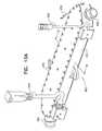
- FIG. 1Bis a simplified exploded view pictorial illustration of the liquid heating unit forming part of the vehicle surface cleaning and de-icing system of FIG. 1A ;
- FIGS. 2A and 2Bare simplified sectional illustrations of the liquid heating unit of FIGS. 1A and 1B , taken along lines IIA-IIA and IIB-IIB of FIG. 1A , respectively;
- FIG. 3is a simplified pictorial illustration of a freeze protection element for use in the liquid heating unit of FIGS. 1A-2B ;
- FIGS. 4A and 4Bare simplified sectional illustrations of the freeze protection element of FIG. 3 , taken along lines IVA-IVA and IVB-IVB of FIG. 3 , respectively;
- FIG. 5is a simplified pictorial illustration of a freeze protection element of FIG. 3 in a deformed state
- FIGS. 6A and 6Bare simplified sectional illustrations of the freeze protection element of FIG. 5 , taken along lines VIA-VIA and VIB-VIB of FIG. 5 , respectively;
- FIG. 7is a simplified exploded view pictorial illustration of the manifold of FIGS. 1A-2B ;
- FIGS. 8A and 8Bare simplified sectional illustrations of the manifold of FIGS. 1A-2B and 7 , taken along lines VIII-VIII of FIG. 1B ;
- FIG. 9is a simplified sectional illustration of a manifold for use with the liquid heating unit of FIGS. 1A-2B , in accordance with another preferred embodiment of the present invention.
- FIG. 10Ais a simplified pictorial illustration of a liquid heater for use in the system of FIGS. 1A-2B , in accordance with another preferred embodiment of the present invention.
- FIG. 10Bis a simplified exploded view pictorial illustration of the liquid heater of FIG. 10A ;
- FIG. 11is a simplified sectional illustration of the liquid heater of FIGS. 10A and 10B , taken along lines XI-XI of FIG. 10A ;
- FIG. 12is a simplified sectional illustration of a liquid heater, similar to the liquid heater of FIGS. 10A-11 , constructed and operative in accordance with another embodiment of the present invention.
- FIG. 13is a simplified sectional illustration of another liquid heater, constructed and operative in accordance with another embodiment of the present invention.
- FIG. 14is a simplified schematic illustration of a system for heating liquid for use by a vehicle fuel cell, constructed and operative in accordance with another preferred embodiment of the present invention.
- FIGS. 15A and 15Bare simplified schematic illustrations of a vehicle surface cleaning and de-icing system including vehicle surface selection functionality, constructed and operative in accordance with another preferred embodiment of the present invention.
- FIG. 16is a simplified flow chart of a preferred mode of operation of a vehicle surface cleaning and de-icing system of FIGS. 15A and 15B .
- vehicleas used in the context of the present patent application and in the claims can refer to any type of wheeled vehicle having windows or any other interior or exterior surface requiring cleaning and/or de-icing, such as an automobile or a truck, as well as a boat or an airplane.
- the systems and methods of the present inventioncan be utilized to clean and/or de-ice any interior or exterior vehicle surface including, for example, front and/or rear windshields, mirrors, windows, headlights, tail lights, radar, radome. It is further appreciated that the cleaning and de-icing system of the present invention may also be used to clean and/or de-ice any vehicle surface that transmits or receives energy, such as, but not limited to, visible light, infrared light, RF energy and UV energy.
- cleaningand “de-icing” as used in the context of the present patent application and in the claims are used interchangeably to refer to apparatus, systems and methods for removing ice, snow and/or any other foreign matter from vehicle interior or exterior surfaces requiring cleaning and/or de-icing.
- non heat conductive materialand “heat conductive material” as used in the context of the present patent application and in the claims, refers to materials which are known in the art to be relatively poor heat conductors and relatively good heat conductors, respectively.
- non electrically conductive materialand “electrically conductive material” as used in the context of the present patent application and in the claims, refers to materials which are known in the art to be relatively poor conductors of electricity and relatively good conductors of electricity, respectively.
- controllermay refer to a controller which forms part of the vehicle surface cleaning and de-icing system of the present invention, or to a vehicle computer or computers or to any combination thereof.
- the controllermay be in communication with a vehicle computer or computers and one or more sensors, as described further hereinbelow.
- FIG. 1Ais a simplified pictorial illustration of a vehicle surface cleaning and de-icing system, constructed and operative in accordance with a preferred embodiment of the present invention, installed in a vehicle
- FIG. 1Bwhich is a simplified exploded view pictorial illustration of a liquid heating unit forming part of the vehicle surface cleaning and de-icing system of FIG. 1A
- FIGS. 2A and 2Bwhich are simplified sectional illustrations of the liquid heating unit of FIGS. 1A and 1B .
- an otherwise conventional vehicle 100is seen to incorporate a vehicle surface cleaning and de-icing system 120 for cleaning and/or de-icing a vehicle surface, such as a windshield 124 .
- the vehicle surface cleaning and de-icing system 120preferably includes a liquid heating unit 126 , including a liquid heating assembly 128 , for heating liquid received from a reservoir 130 , which provides heated liquid, such as water or windshield cleaning liquid, to at least one sprayer 132 for spraying onto windshield 124 .
- Liquid heating unit 126has an inlet 134 , which receives liquid from reservoir 130 , and an outlet 136 through which heated liquid is discharged to at least one sprayer 132 .
- the liquidis driven by a pump 140 , which is generally already present in vehicle 100 for spraying unheated liquid to clean windshield 124 .
- a battery 142provides power to vehicle surface cleaning and de-icing system 120 , and wipers 144 clean melted ice and dirt from the windshield 124 , as is known in the art.
- a controller 146regulates the operation of vehicle surface cleaning and de-icing system 120 , and optionally also controls wipers 144 in conjunction with operation of vehicle surface cleaning and de-icing system 120 .
- One or more temperature sensorsare preferably provided to measure the temperature of the liquid in liquid heating assembly 128 and may also measure the temperature of the at least one sprayer 132 . Additionally, one or more temperature sensors, preferably in communication with controller 146 , may be provided to measure the temperature external to liquid heating assembly 128 , such as a windshield temperature sensor (not shown), a vehicle exterior temperature sensor (not shown) and a vehicle interior temperature sensor (not shown).
- At least one sprayer 132which is located on a wiper arm in the illustrated embodiment, may be located in any other suitable location, such as adjacent windshield 124 or on wipers 144 .
- Controller 146may also be operative to receive additional inputs concerning vehicle operational parameters and/or external conditions from a vehicle computer and/or from existing vehicle sensors.
- liquid heating unit 126comprises a housing 150 including a main housing portion 154 , a removable cover housing portion 156 , a first cap portion 158 and a second cap portion 160 .
- Main housing portion 154preferably defines a first manifold engagement surface 170 defining a liquid inlet aperture 174 and a second manifold engagement surface 176 defining a liquid outlet aperture 178 .
- Main housing portion 154also preferably defines an interior volume in which is disposed liquid heating assembly 128 . At least one heating element 182 is disposed within liquid heating assembly 128 for heating liquid therein. As seen particularly in FIG. 2B , liquid inlet aperture 174 and liquid outlet aperture 178 are both in fluid communication with liquid heating assembly 128 and a manifold 200 .
- liquid heating assembly 128may be any liquid heating assembly suitable for use in a vehicle, including but not limited to those described in applicants'/assignee's U.S. Pat. Nos. 6,164,564; 6,615,438; 6,669,109; 6,892,417; 7,108,754 and 7,171,716, applicants'/assignee's U.S. patent application Ser. Nos. 11/610,287; 10/700,141; 10/477,486; 10/588,165 and 10/531,979 and applicants'/assignee's PCT Application Serial No. PCT/IL2006/001209, the disclosures of which are hereby incorporated by reference.
- Manifold 200is preferably configured, at one end thereof, to engage first manifold engagement surface 170 and second manifold engagement surface 176 via connectors 202 and 204 , respectively.
- an inflow connector 206for connecting to inlet 134 , providing liquid from reservoir 130
- an outflow connector 208for connecting to an outlet 136 providing liquid to at least one sprayer 132 .
- Liquidis preferably supplied to liquid heating assembly 128 from reservoir 130 via inlet 134 , manifold 200 and liquid inlet aperture 174 .
- Liquidis preferably provided from liquid heating assembly 128 to at least one sprayer 132 via liquid outlet aperture 178 , manifold 200 and outlet 136 .
- Liquid heating unit 126also preferably includes a freeze protection element 250 to prevent damage to housing 150 and liquid heating assembly 128 in the event of freezing of liquid within liquid heating unit 126 .
- Freeze protection element 250is preferably formed of a flexible, resilient material, such as silicon or rubber. In the event of expansion of the liquid in liquid heating assembly 128 due to freezing, freeze protection element 250 is operative to deform inwardly, as described further hereinbelow in reference to FIGS. 5-6B , and thereby prevent damage to liquid heating unit 126 .
- Freeze protection element 250preferably comprises a generally cylindrical container portion 252 defining an interior volume 254 . Freeze protection element 250 also preferably includes a generally annular sealing element 256 configured to engage an upper surface 260 of main housing portion 154 .
- freeze protection element 250is preferably inserted into a volume 270 defined in main housing portion 154 above liquid heating assembly 128 .
- Freeze protection element 250is preferably in sealing engagement with an interior surface 275 of main housing portion 154 to prevent liquid passage from liquid heating assembly 128 into interior volume 254 .
- First cap portion 158preferably engages main housing portion 154 and is operative to prevent sealing element 256 from disengaging with upper surface 260 of main housing portion 154 .
- FIG. 3is a simplified pictorial illustration
- FIGS. 4A and 4Bare simplified sectional illustrations, of a preferred embodiment of freeze protection element 250 of FIGS. 1A-2B .
- freeze protection element 250preferably comprises an integrally formed, generally cylindrical wall portion 280 , a generally circular bottom portion 282 and generally annular sealing element 256 .
- Freeze protection element 250is preferably formed of a flexible, resilient material and is configured to be inwardly deformable when pressure is applied to circular floor portion 282 from below.
- annular sealing element 256is preferably formed with an overhang 284 configured to engage upper surface 260 of main housing portion 154 . Sealing element 256 is operative to generally maintain freeze protection element 250 in proper orientation within volume 270 .
- FIG. 5is a simplified pictorial illustration
- FIGS. 6A and 6Bare simplified sectional illustrations, of the freeze protection element 250 of FIGS. 1A-4B in a deformed state.
- freeze protection element 250when pressure is applied to an outer surface of generally circular bottom portion 282 of freeze protection element 250 from outside freeze protection element 250 , such as may be caused by freezing of liquid in liquid heating assembly 128 , as indicated by arrow 290 , freeze protection element 250 is operative to deform inwardly into interior volume 254 .
- Freeze protection element 250is preferably operative to deform inwardly in at least two perpendicular axial directions, and may be deformable is all three axial directions.
- cylindrical wall portion 280 of freeze protection element 250may deform inwardly along both an X axis, as seen in FIG. 6A , and along a Y axis, as seen in FIG. 6B .
- Circular bottom portion 282may also deform inwardly along a Z axis. It is appreciated that the flexible and resilient properties of freeze protection element 250 enable freeze protection element 250 to simultaneously deform along multiple axes. It is also appreciated that the provision of interior volume 254 of freeze protection element 250 enables freeze protection element 250 to deform inwardly generally without any outward deformation.
- FIG. 7is a simplified exploded view pictorial illustration of manifold 200 of FIGS. 1A-2B
- FIGS. 8A and 8Bare simplified sectional illustrations of manifold 200 in two different sprayer configurations.
- manifold 200preferably includes an input conduit 300 , forming part of a first fluid flow path from reservoir 130 to liquid heating assembly 128 , as indicated by arrows 305 , and an output conduit 310 , forming part of a second fluid flow path from liquid heating assembly 128 to at least one sprayer 132 , as indicated by arrows 315 .
- Input conduit 300is preferably connected at inflow connector 206 to inlet 134 ( FIG. 1A ) and output conduit 310 is preferably connected at outflow connector 208 to outlet 136 .
- Manifold 200also includes a connecting conduit 320 connecting input conduit 300 and output conduit 310 .
- Input conduit 300includes a first one-way valve 330 and connecting conduit 320 includes a second one-way valve 340 .
- First one-way valve 330is a normally closed valve, which prevents fluid flow from liquid heating assembly 128 to reservoir 130 , and is opened when pump 140 ( FIG. 1A ) is operative to provide liquid under pressure from reservoir 130 to liquid heating assembly 128 .
- Second one-way valve 340is a normally open valve, when pump 140 is closed, which allows fluid to flow from output conduit 310 to input conduit 300 , and is closed when pump 140 is operative to provide liquid under pressure from reservoir 130 to liquid heating assembly 128 .
- FIG. 8Aillustrates the fluid flows provided by manifold 200 when used with a vehicle surface cleaning and de-icing system 120 including at least one additional one-way valve 350 , along the second fluid flow path from liquid heating assembly 128 to sprayers 132 , upstream of manifold 200 and downstream of sprayers 132 .
- Additional one-way valve 350is a normally closed valve, when pump 140 is closed, which is is opened by pressure from liquid flowing to sprayers 132 from liquid heating assembly 128 when pump 140 is operative.
- Additional one-way valve 350is generally provided in a vehicle to allow liquid to remain in outlet 136 when pump 140 is closed and thereby provides a shorter time interval, between the actuation of pump 140 and provision of liquid to sprayers 132 , than when additional one-way valve 350 is not provided, as described hereinbelow with reference to FIG. 8B .
- the combination of second one-way valve 340 and additional one-way valve 350is also operative to prevent liquid in outlet 136 from exiting through sprayers 132 when pump 140 is closed.
- manifold 200is operative to provide the following fluid flows during operation of liquid heating unit 126 .
- pump 140is operative, in response to an input from controller 146 , to provide liquid to liquid heating assembly 128 , liquid under pressure is provided through inlet 134 to input conduit 300 .
- the liquidis operative to open first one-way valve 330 to allow liquid to flow in the direction of arrows 305 , and to close second one-way valve 340 so that liquid from liquid heating assembly 128 flows through output conduit 310 , in the direction of arrows 315 , through outlet 136 and additional one-way valve 350 to sprayers 132 .
- first one-way valve 330closes and prevents liquid flow from liquid heating assembly 128 to reservoir 130 .
- second one-way valve 340is open so that excess liquid and vapor, located upstream of first one-way valve 330 and downstream of additional one-way valve 350 , including liquid and vapor in liquid heating assembly 128 , output conduit 310 , or outlet 136 , will flow through connecting conduit 320 , in the direction of arrows 360 , through input conduit 300 to reservoir 130 .
- the provision of second one-way valve 340prevents this excess liquid and vapor from dripping through sprayers 132 onto windshield 124 , or other vehicle surfaces located adjacent sprayers 132 .
- each of multiple sprayers 132must be located upstream of at least one additional valve 350 .
- FIG. 8Billustrates the fluid flows provided by manifold 200 when used with a vehicle surface cleaning and de-icing system 120 not including additional one-way valve 350 of FIG. 8A along the second fluid flow path from liquid heating assembly 128 to sprayers 132 upstream of manifold 200 and downstream of sprayers 132 .
- manifold 200is operative to provide the following fluid flows during operation of liquid heating unit 126 .
- pump 140is operative, in response to an input from controller 146 , to provide liquid to liquid heating assembly 128 , liquid under pressure is provided through inlet 134 to input conduit 300 .
- the liquidis operative to open first one-way valve 330 to allow liquid to flow in the direction of arrows 305 , and to close second one-way valve 340 so that liquid from liquid heating assembly 128 flows through output conduit 310 , in the direction of arrows 315 , through outlet 136 to sprayers 132 .
- first one-way valve 330closes and prevents liquid flow from liquid heating assembly 128 to reservoir 130 .
- second one-way valve 340opens so that excess liquid remaining upstream of valve 340 , including liquid in outlet 136 and output conduit 310 , will flow through connecting conduit 320 , in the direction of arrows 360 , through input conduit 300 to reservoir 130 .
- second one-way valve 340 in manifold 200thus provides for the draining of fluid remaining in the fluid flow path upstream of second one-way valve 340 to reservoir 130 upon the conclusion of spraying.
- manifold 200thus provides multiple fluid flow paths and is suitable for use both in vehicles that include additional one-way valve 350 and vehicles that do not include additional one-way valve 350 .
- FIG. 9is a simplified sectional illustration of a manifold for use with the liquid heating unit of FIGS. 1-2B , in accordance with another preferred embodiment of the present invention.
- a manifold 400preferably includes an input conduit 402 , forming part of a first fluid flow path from reservoir 130 to liquid heating assembly 128 , as indicated by arrows 405 , and an output conduit 410 , forming part of a second fluid flow path from liquid heating assembly 128 to sprayers 132 , as indicated by arrows 415 .
- Input conduit 402is preferably connected at inflow connector 416 to inlet 134 ( FIG. 1A ) and output conduit 410 is preferably connected at outflow connector 418 to outlet 136 ( FIG. 1A ).
- Manifold 400also includes a first connecting conduit 420 and a second connecting conduit 422 connecting input conduit 402 and output conduit 410 .
- Input conduit 402includes a first one-way valve 430
- first connecting conduit 420includes a second one-way valve 440
- second connecting conduit 422includes a bypass valve 450 .
- First one-way valve 430is a normally closed valve, which prevents fluid flow from liquid heating assembly 128 to reservoir 130 and is opened when pump 140 ( FIG. 1A ) is operative to provide liquid under pressure from reservoir 130 to liquid heating assembly 128 .
- Second one-way valve 440is a normally open valve, when pump 140 is closed, which allows fluid to flow from output conduit 410 to input conduit 402 and is closed when pump 140 is operative to provide liquid under pressure from reservoir 130 to liquid heating assembly 128 .
- Bypass valve 450is a spring loaded one-way valve which permits liquid to bypass liquid heating assembly 128 and flow directly from input conduit 402 through output conduit 410 and outlet 136 to sprayers 132 , when the pressure differential thereacross reaches a predetermined threshold, typically 0.3-0.5 bar, which indicates the existence of a blockage in the fluid flow path through valve 430 and the liquid heating assembly 128 .
- a predetermined thresholdtypically 0.3-0.5 bar
- Manifold 400provides fluid flows similar to the fluid flows provided by manifold 200 , as described hereinabove with reference to FIGS. 8A and 8B . Manifold 400 is thus also suitable for use both in vehicles that include additional one-way valve 350 , as described hereinabove with reference to FIG. 8A , and vehicles that do not include additional one-way valve 350 , as described hereinabove with reference to FIG. 8B .
- FIGS. 10A , 10 B and 11are, respectively, a simplified assembled pictorial illustration, a simplified exploded view pictorial illustration and a simplified sectional illustration of a liquid heater for use in the system of FIGS. 1A-2B .
- a liquid heater 600comprises a housing element 610 including an inlet 612 and an outlet 614 .
- Housing element 610is preferably formed of plastic, but may also be made of any suitable material, such as aluminum.
- Disposed within housing element 610is at least one heat dissipation element 616 , preferably a pair of heat dissipation elements 616 , having formed, on an inward facing surface 618 thereof, protruding elements, such as ridges or protrusions 620 .
- Ridges or protrusions 620 of heat dissipation element 616define at least one liquid flow path, such as flow channels 622 , preferably providing a large contact surface area for maximizing heat transfer to a liquid flowing therethrough.
- Flow channels 622are preferably in fluid communication with inlet 612 and outlet 614 .
- An outward facing surface of heat dissipation element 616preferably engages an electronically insulative, thermal conductive pad 626 .
- An outward facing surface of thermal conductive pad 626preferably engages a heating element 630 .
- Electronically insulative, thermal conductive pad 626is preferably formed of a non-electrically conductive, heat conductive material and provides electrical insulation between the heat dissipation element 616 and heating element 630 while providing good thermal conductivity.
- Heating element 630preferably comprises a substrate, such as a printed circuit board (PCB) 634 , including at least one electrical circuit having formed on at least a portion thereof at least one heating trace 640 , which preferably comprises copper, nickel or nickel-chrome. It is appreciated that heating trace 640 may comprise a different material than the material of the electrical circuit upon which it is formed or may comprise the same material as the electrical circuit upon which it is formed.
- PCBprinted circuit board
- Heating trace 640is preferably arranged in a generally serpentine arrangement to maximize the surface area of PCB 634 covered thereby and to maximize the heat provision therefrom.
- heating element 630includes two heating traces 640 , each arranged in a generally serpentine arrangement.
- PCB 634may have mounted thereon sensors and other control circuitry elements, as described hereinbelow with reference to FIG. 12 .
- heating trace 640is preferably formed of a material, such as copper, nickel or nickel-chrome, having increased resistance as it is heated, thus generating less current, less power and less heat energy as the temperature increases. It is appreciated that by measuring the current through heating trace 640 and the voltage thereon, the resistance thereof may be calculated and correlated to the temperature thereof. This temperature generally provides an average temperature along heating trace 640 , rather than a single location temperature that would be provided by a temperature sensor, and is preferably provided as an input for use in controlling heating element 630 .
- Liquid heater 600may also include a power disconnect, such as a thermal fuse (not shown), as a protection mechanism against overheating. As described further hereinbelow, liquid heater 600 may also include at least one sensor and/or control circuitry integrated with PCB 634 to provide low cost, robust design and ease of assembly thereof.
- a power disconnectsuch as a thermal fuse (not shown)
- thermal fusenot shown
- liquid heater 600may also include at least one sensor and/or control circuitry integrated with PCB 634 to provide low cost, robust design and ease of assembly thereof.
- An outward facing surface of heating element 630preferably engages a thermal insulative pad 644 .
- An outward facing surface of thermal insulative pad 644preferably engages a pressure plate 650 .
- Pressure plate 650preferably is operative to ensure that heating element 630 is generally evenly pressed against, heat dissipation element 616 .
- Liquid heater 600also preferably includes a sealing frame 660 between dissipation element 616 and housing element 610 .
- housing element 610 , dissipation element 616 , pad 644 , sealing frame 660 and pressure plate 650are provided with a plurality of apertures 670 therearound, operative to accommodate screws or other connecting elements.
- Pressure plate 650is preferably connected to housing element 610 by connecting elements such as screws, which preferably extend through apertures 670 in pressure plate 650 , pad 644 , dissipation element 616 and sealing frame 660 into apertures 670 in housing element 610 .
- a liquidpreferably enters the system through inlet 612 , and flows through flow channels 622 in thermal contact with ridges or protrusions 620 of heat dissipation elements 616 and is heated thereby. It is appreciated that the provision of electronically insulative, thermal conductive pads 626 provide electrical insulation between heat dissipation elements 616 and heating elements 630 while providing thermal conductivity to provide efficient heat transfer to liquid flowing through flow channels 622 .
- liquid heater 600is particularly suitable for heating of liquids used in a vehicle, such as a fluid for cleaning or de-icing a vehicle surface. As described further hereinbelow, liquid heater 600 is also suitable for heating liquid fuel cell coolant, where the temperature of the fuel cell coolant must be maintained at a temperature greater than a minimum threshold temperature in order for the fuel cell to function properly.
- liquid heater 600is suitable for heating high liquid flows, typically from 5-160 liters per minute (lpm).
- Liquid heater 600preferably includes two operating modes, an idle mode, during which heating elements 630 are not energized and do not generate heat, and an operational mode, where heating elements 630 are energized and generate heat. Liquid heater 600 thus operates with little or no thermal hysteresis, since heat is generated only when heating elements 630 are energized and heat is not generated when power is removed from heating elements 630 .
- the operational mode of liquid heater 600may also include setting a power level for the operation of heating elements 630 .
- the power levelmay be based on sensing a temperature of the liquid at any suitable point along the flow thereof, such as within liquid heater 600 or upstream or downstream therefrom, and comparing the liquid temperature to a threshold temperature, or any other suitable method.
- Liquid heater 600may include at least one temperature sensor to monitor the temperature of the liquid to prevent overheating of the liquid. Additionally, liquid heater 600 may also include at least one temperature sensor to monitor the temperature of liquid heater 600 and to prevent excessive heating thereof. Additional temperature sensors may also be provided, such as a temperature sensor to measure a temperature within a vehicle external to liquid heater 600 or a temperature external to the vehicle.
- Liquid heater 600is also designed to minimize pressure drop at all flow rates.
- Heat dissipation elements 616include a large surface area to maximize contact with the fluid and a flow channel designed to maximize the transfer of heat to the fluid.
- Liquid heater 600also preferably includes electrical connectors 676 and 678 , and temperature sensor connector 680 .
- An inlet connector 682is attached to liquid heater 600 at inlet 612 is and an outlet connector 684 is attached to liquid heater 600 at outlet 614 .
- a liquid heater 700comprises a housing element 710 including an inlet 712 and an outlet 714 .
- Housing element 710is preferably formed of plastic, but may also be made of any suitable material, such as aluminum.
- Disposed within housing element 710is at least one heat dissipation element 716 , preferably a pair of heat dissipation elements 716 , having formed, on an inward facing surface thereof, protruding elements, such as ridges or protrusions.
- Ridges or protrusions of heat dissipation element 716preferably define flow channels 722 providing a large contact surface area for maximizing heat transfer to a liquid flowing therethrough.
- Flow channels 722are preferably in fluid communication with inlet 712 and outlet 714 .
- An outward facing surface of heat dissipation element 716preferably engages an electronically insulative, thermal conductive pad 726 .
- An outward facing surface of thermal conductive pad 726preferably engages a heating element 730 .
- Electronically insulative, thermal conductive pad 726is preferably formed of a non-electrically conductive, heat conductive material and provides electrical insulation between the heat dissipation element 716 and heating element 730 while providing good thermal conductivity.
- Heating element 730preferably comprises a substrate, such as a printed circuit board (PCB) 734 , including at least one electrical circuit having formed on at least a portion thereof at least one heating trace 740 , preferably comprises copper, nickel or nickel-chrome. It is appreciated that heating trace 740 may comprise a different material than the material of the electrical circuit upon which it is formed or may comprise the same material as the electrical circuit upon which it is formed.
- PCBprinted circuit board
- Heating trace 740is preferably arranged in a generally serpentine arrangement to maximize the surface area of PCB 734 covered thereby and to maximize the heat provision therefrom.
- heating element 730includes two heating traces 740 , each arranged in a generally serpentine arrangement.
- the PCB 734may have mounted thereon sensors and other control circuitry elements 742 .
- heating trace 740is preferably formed of a material, such as copper, nickel or nickel-chrome, having increased resistance as it is heated, thus generating less current, less power and less heat energy as the temperature increases. It is appreciated that by measuring the current through heating trace 740 and the voltage thereon, the resistance thereof may be calculated and correlated to the temperature thereof. This temperature generally provides an average temperature along heating trace 740 , rather than a single location temperature that would be provided by a temperature sensor, and is preferably provided as an input for use in controlling heating element 730 .
- Liquid heater 700may also include a power disconnect, such as a thermal fuse (not shown), as a protection mechanism against overheating.
- a power disconnectsuch as a thermal fuse (not shown), as a protection mechanism against overheating.
- heating element 730preferably engages a thermal insulative pad 744 .
- An outward facing surface of thermal insulative pad 744preferably engages a pressure plate 750 .
- Pressure plate 750preferably is operative to ensure that heating element 730 is generally evenly pressed against the heat dissipation element 716 .
- Liquid heater 700also preferably includes a sealing frame (not shown) between dissipation element 716 and housing element 710 .
- housing element 710 , dissipation element 716 , pad 744 , sealing frame and pressure plate 750are provided with a plurality of apertures therearound, operative to accommodate screws or other connecting elements.
- Pressure plate 750is preferably connected to housing element 710 by connecting elements such as screws, which preferably extend through apertures in pressure plate 750 , pad 744 , dissipation element 716 and sealing frame into apertures formed in housing element 710 .
- a liquidpreferably enters the system through inlet 712 , and flows through flow channels 722 in thermal contact with ridges or protrusions of heat dissipation elements 716 and is heated thereby. It is appreciated that the provision of electronically insulative, thermal conductive pads 726 provide electrical insulation between heat dissipation elements 716 and heating elements 730 while providing thermal conductivity to provide efficient heat transfer to liquid flowing through flow channels 722 .
- liquid heater 700is particularly suitable for heating of liquids used in a vehicle, such as a fluid for cleaning or de-icing a vehicle surface. As described further hereinbelow, liquid heater 700 is also suitable for heating liquid fuel cell coolant, where the temperature of the fuel cell coolant must be maintained at a temperature greater than a minimum threshold temperature in order for the fuel cell to function properly.
- liquid heater 700is suitable for heating high liquid flows, typically from 5-160 liters per minute (lpm).
- Liquid heater 700preferably includes two operating modes, an idle mode, during which heating elements 730 are not energized and do not generate heat, and an operational mode, where heating elements 730 are energized and generate heat. Liquid heater 700 thus operates with little or no thermal hysteresis, since heat is generated only when heating elements 730 are energized and heat is not generated when power is removed from heating elements 730 .
- the operational mode of liquid heater 700may also include setting a power level for the operation of heating elements 730 .
- the power levelmay be based on sensing a temperature of the liquid at any suitable point along the flow thereof, such as within liquid heater 700 or upstream or downstream therefrom, and comparing the liquid temperature to a threshold temperature, or any other suitable method.
- Liquid heater 700may include at least one temperature sensor to monitor the temperature of the liquid to prevent overheating of the liquid. Additionally, liquid heater 700 may also include at least one temperature sensor to monitor the temperature of liquid heater 700 and to prevent excessive heating thereof. Additional temperature sensors may also be provided, such as a temperature sensor to measure a temperature within a vehicle external to liquid heater 700 or a temperature external to the vehicle.
- Liquid heater 700is also designed to minimize pressure drop at all flow rates.
- Heat dissipation elements 716include a large surface area to maximize contact with the fluid and a flow channel designed to maximize the transfer of heat to the fluid.
- a liquid heater 800comprises a housing element 810 including an inlet 812 and an outlet 814 .
- Housing element 810is preferably formed of plastic, but may also be made of any suitable material, such as aluminum.
- Heat transfer element 816Disposed within housing element 810 is at least one heat transfer element 816 , preferably a pair of heat transfer elements 816 , having formed, on an inward facing surface thereof, protruding elements, such as ridges or protrusions.
- Heat transfer element 816preferably comprises a substrate, such as a metal-backed circuit board, such as a Thermal Clad substrate commercially available from The Bergquist Company, 18930 West 78 th Street, Chanhassen, Minn. 55317, U.S.A., with a resistive heating element 818 formed on an outer surface thereof.
- Ridges or protrusions of heat transfer elements 816preferably define flow channels 822 providing a large contact surface area for maximizing heat transfer to a liquid flowing therethrough.
- Flow channels 822are preferably in fluid communication with inlet 812 and outlet 814 .
- Resistive heating element 818preferably comprises at least one heating trace, which preferably includes copper, nickel or nickel-chrome, formed on at least a portion of an electrical circuit formed on the substrate. It is appreciated that the heating trace of heating element 818 may be formed of a different material than the material of the electrical circuit upon which it is formed or may comprise the same material as the electrical circuit upon which it is formed.
- the heating trace of resistive heating element 818is preferably arranged in a generally serpentine arrangement to maximize the surface area of outer surface of heat transfer element 816 covered thereby and to maximize the heat provision therefrom.
- resistive heating element 818includes two heating traces, each arranged in a generally serpentine arrangement.
- the substrate of heat transfer element 816may have mounted thereon sensors and other control circuitry elements 842 .
- resistive heating elements 818are preferably formed of a material, such as copper, nickel or nickel-chrome, having increased resistance as it is heated, thus generating less current, less power and less heat energy as the temperature increases. It is appreciated that by measuring the current through resistive heating elements 818 and the voltage thereon, the resistance thereof may be calculated and correlated to the temperature thereof. This temperature generally provides an average temperature along resistive heating elements 818 , rather than a single location temperature that would be provided by a temperature sensor, and is preferably provided as an input for use in controlling heating elements 818 .
- Liquid heater 800may also include a power disconnect, such as a thermal fuse (not shown), as a protection mechanism against overheating.
- a power disconnectsuch as a thermal fuse (not shown), as a protection mechanism against overheating.
- Liquid heater 800preferably also includes a cover element 850 and a sealing frame (not shown) between heat transfer elements 816 and housing element 810 .
- housing element 810 , heat transfer elements 816 , sealing frame and cover element 850are provided with a plurality of apertures therearound, operative to accommodate screws or other connecting elements.
- Cover elements 850are preferably connected to housing element 810 by connecting elements such as screws, which preferably extend through apertures in cover elements 850 , heat transfer elements 816 and sealing frame into apertures formed in housing element 810 .
- a liquidpreferably enters the system through inlet 812 , and flows through flow channels 822 in thermal contact with ridges or protrusions of heat transfer elements 816 and is heated thereby.
- liquid heater 800is particularly suitable for heating of liquids used in a vehicle, such as a fluid for cleaning or de-icing a vehicle surface. As described further hereinbelow, liquid heater 800 is also suitable for heating liquid fuel cell coolant, where the temperature of the fuel cell coolant must be maintained at a temperature greater than a minimum threshold temperature, in order for the fuel cell to function properly.
- liquid heater 800is suitable for heating high liquid flows, typically from 5-160 liters per minute (lpm).
- Liquid heater 800preferably includes two operating modes, an idle mode, during which heating elements 818 are not energized and do not generate heat, and an operational mode, where heating elements 818 are energized and generate heat.
- Liquid heater 800thus operates with little or no thermal hysteresis, since heat is generated only when heating elements 818 are energized and heat is not generated when power is removed from heating elements 818 .
- the operational mode of liquid heater 800may also include setting a power level for the operation of heating elements 818 .
- the power levelmay be based on sensing a temperature of the liquid at any suitable point along the flow thereof, such as within liquid heater 800 or upstream or downstream therefrom, and comparing the liquid temperature to a threshold temperature, or any other suitable method.
- Liquid heater 800may include at least one temperature sensor to monitor the temperature of the liquid to prevent overheating of the liquid. Additionally, liquid heater 800 may also include at least one temperature sensor to monitor the temperature of liquid heater 800 and to prevent excessive heating thereof. Additional temperature sensors may also be provided, such as a temperature sensor to measure a temperature within a vehicle external to liquid heater 800 or a temperature external to the vehicle.
- Liquid heater 800is also designed to minimize pressure drop at all flow rates.
- Heat transfer elements 816include a large surface area to maximize contact with the fluid and a flow channel designed to maximize the transfer of heat to the fluid.
- FIG. 14is a simplified schematic illustration of a system for heating liquid for use by a vehicle fuel cell, constructed and operative in accordance with another preferred embodiment of the present invention.
- the system 900 of the present inventionincludes a closed loop liquid circulation subsystem 904 controlled by a controller 908 .
- Closed loop liquid circulation subsystem 904includes a liquid heater 912 , such as liquid heater 600 of FIGS. 10A-11 , liquid heater 700 of FIG. 12 , liquid heater 800 of FIG. 13 or any other suitable liquid heater.
- Liquid heater 912is preferably located in a vehicle upstream of a pump 916 supplying liquid to a fuel cell 920 .
- a valve 924 and a radiator 928are located downstream from fuel cell 920 .
- a flow path directly from fuel cell 920 to liquid heater 912 , bypassing radiator 928 , via a bypass valve 932is also provided.
- closed loop liquid circulation subsystem 904includes a first liquid conduit 936 between fuel cell 920 and valves 924 and 932 and a second liquid conduit 940 between radiator 928 and liquid heater 912 .
- closed loop circulation subsystem 904defines a first liquid flow path, from liquid heater 912 via pump 916 to fuel cell 920 and back to liquid heater 912 through bypass valve 932 , and a second liquid flow path, from liquid heater 912 via pump 916 to fuel cell 920 , to radiator 928 through valve 924 and back to liquid heater 912 .
- Controller 908is preferably in electrical communication with liquid heater 912 , pump 916 , fuel cell 920 , valve 924 , bypass valve 932 and radiator 928 . Controller 908 is preferably operative to control the flow of liquid provided to fuel cell 920 to insure that the liquid is within an allowable temperature range suitable for operation of fuel cell 920 .
- Controller 908is preferably operative to receive inputs from at least one temperature sensor, such as a temperature sensor (not shown) measuring the temperature of the liquid within liquid heater 912 , a temperature sensor (not shown) measuring the temperature of the liquid within pump 916 , a temperature sensor (not shown) measuring the temperature of the liquid within fuel cell 920 and/or a temperature sensor (not shown) measuring the temperature of the liquid within radiator 928 .
- At least one additional temperature sensor (not shown) in communication with controller 908may also be provided to measure the temperature of the liquid at points along the first and second liquid flow paths of closed loop circulation subsystem 904 , such as along first liquid conduit 936 and second liquid conduit 940 .
- Additional temperature sensors in communication with controller 908may be provided, such as one or more temperature sensors 950 to measure a temperature outside of the vehicle and/or a temperature within the vehicle external to the engine compartment.
- Controller 908is operative to monitor the temperature of the liquid within closed loop circulation subsystem 904 and control the operation of liquid heater 912 to ensure that the operating temperature of fuel cell 920 is maintained within a predetermined range, typically between 60° C. and 95° C.
- controller 908is preferably operative to set a power level of liquid heater 912 to a maximum heating level.
- controller 908may be operative to set a power level of liquid heater 912 to less than the maximum.
- any suitable control methodsuch as on/off, PID, or other control method, may be used by controller 908 to control the operation of liquid heater 912 .
- controller 908When the temperature of the liquid in fuel cell 920 exceeds a second threshold, typically the upper extent of the predetermined range, controller 908 is operative to turn off the power to liquid heater 912 .
- Controller 908may also be operative to control a flow rate of pump 916 based on the liquid temperature sensed and other available information to provide a suitable flow rate of liquid to fuel cell 920 . It is appreciated that at least one flow sensor (not shown) in communication with controller 908 may be provided, such as a flow sensor located along first liquid conduit 936 , second liquid conduit 940 , in pump 916 or any other suitable location along common portions of the first and second flow paths.
- Controller 908is also operative to monitor the temperature of the liquid within closed loop circulation subsystem 904 to control liquid flow through valve 924 and bypass valve 932 .
- controller 908is preferably operative to close valve 924 and open bypass valve 932 so that liquid flows along the first liquid flow path from fuel cell 920 to liquid heater 912 through bypass valve 932 .
- controller 908is preferably operative to open valve 924 and close bypass valve 932 so that liquid flows along the second liquid flow path from fuel cell 920 to radiator 928 through valve 924 and then to liquid heater 912 .
- radiator 928 of closed loop liquid circulation subsystem 904is provided to reduce the temperature of the liquid flowing through closed loop liquid circulation subsystem 904 in the event the temperature of the liquid exceeds the second predetermined threshold.
- controller 908may receive additional inputs relating to the vehicle operating parameters, such as vehicle velocity, vehicle engine operating parameters, and other information provided by a vehicle computer, and may be operative to receive an actuation input, which may be a manually generated input signal or an automatically generated input signal, and a de-actuation input, which may be a manually generated input signal or an automatically generated input signal. Controller 908 is preferably in communication with a vehicle computer (not shown) to provide operating information relating to system 900 to the vehicle computer.
- Fuel cell 920is a conventional fuel cell. To provide the energy requirements for the operation of a vehicle, fuel cell 920 must achieve a desired current density level without degradation of fuel cell components. To provide optimal operation, the normal operating temperature of fuel cell 920 needs to be maintained within a predetermined range, typically between 60° C. and 95° C. Additionally, at operating temperatures of less than 25° C. fuel cell 920 operates inefficiently. It is appreciated that fuel cell 920 may be operative to reach the optimal temperature range with or without the operation of system 900 and system 900 may be operative to maintain the temperature of fuel cell 920 within the required range.
- System 900may be operative to provide heated liquid to fuel cell 920 to reduce the time period needed by fuel cell 920 to reach the optimal operating temperature range and thereby increase the efficiency of fuel cell 920 during freezing and cold ambient conditions.
- system 900may be utilized with any other system utilizing a fuel cell. It is also appreciated that controller 908 and the functionality thereof may be part of liquid heater 912 , pump 916 , fuel cell 920 or radiator 928 or may be incorporated into a vehicle computer or any combination thereof.
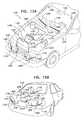
- FIGS. 15A and 15Bare simplified schematic illustrations of a vehicle surface cleaning and deicing system including vehicle surface selection functionality, constructed and operative in accordance with another preferred embodiment of the present invention.
- a vehicle 1100includes a vehicle surface cleaning and de-icing system 1102 .
- Vehicle surface cleaning and de-icing system 1102preferably includes at least one liquid reservoir, such as a liquid reservoir 1106 , which contains liquid, such as water or windshield cleaning liquid.
- at least one pumpsuch as a pump 1108 , supplies the liquid to at least one liquid heating unit 1110 through at least one liquid inflow conduit 1112 .
- Liquid from at least one liquid heating unit 1110is preferably discharged via at least one liquid outflow conduit 1116 and a plurality of liquid spray supply conduits 1118 which supply liquid to a plurality of sprayers 1120 located adjacent to a plurality of vehicle surfaces 1122 , such as headlights, windshield, rear window and tail lights.
- a plurality of wipers 1126are located in front of vehicle surfaces 1122 to wipe liquid and clean or de-ice vehicle surfaces 1122 .
- At least one of vehicle surfaces 1122is equipped with a dirt sensor 1128 , preferably in communication with a vehicle surface cleaning and de-icing system controller 1150 and/or the existing vehicle computer. Dirt sensors 1128 are preferably operative to send individually recognizable signals to the vehicle surface cleaning and de-icing system controller 1150 .
- Additional sensorssuch as a liquid level sensor (not shown) associated with reservoir 1106 , a rain sensor (not shown), at least one temperature sensor, such as a temperature sensor 1152 located on an external vehicle surface, a temperature sensor (not shown) associated with reservoir 1106 , a temperature sensor (not shown) associated with liquid heating unit 1110 , a temperature sensor (not shown) located internal to vehicle 1100 , and other sensors, which provide input to vehicle surface cleaning and de-icing system controller 1150 and/or the vehicle computer, may also be provided.
- a temperature sensor 1152located on an external vehicle surface
- a temperature sensorassociated with reservoir 1106
- a temperature sensorassociated with liquid heating unit 1110
- a temperature sensorlocated internal to vehicle 1100
- other sensorswhich provide input to vehicle surface cleaning and de-icing system controller 1150 and/or the vehicle computer, may also be provided.
- liquid heating unit 1110 and pump 1108are preferably in electrical communication with the vehicle surface cleaning and de-icing system controller 1150 and/or the vehicle computer. It is also appreciated that the vehicle surface cleaning and de-icing system controller 1150 is preferably in electrical communication with the vehicle computer. Alternatively, the functionality of the vehicle surface cleaning and de-icing system controller 1150 may be included in the vehicle computer and the vehicle surface cleaning and de-icing system controller 1150 may be obviated.
- Liquid heating unit 1110is connected via electric cables 1154 to a vehicle battery 1156 .
- Liquid heating unit 1110may be any liquid heating device suitable for use in a vehicle, including but not limited to those described in applicants'/assignee's U.S. Pat. Nos. 6,164,564; 6,615,438; 6,6,669,105; 6,892,4171; 7,108,754 and 7,171,716, applicants'/assignee's U.S. patent application Ser. Nos. 11/610,287; 10/700,141; 10/477,486; 10/531,979 and 10/588,165 and applicants'/assignee's PCT Application Serial No. PCT/IL2006/001209, the disclosures of which are hereby incorporated by reference.
- vehicle surface cleaning and de-icing system 1102may utilize an existing vehicle reservoir (not shown) to provide liquid to liquid heating unit 1110 .
- An actuator panel 1160is typically located on the vehicle dashboard and includes an actuator (not shown) in communication with a vehicle surface cleaning and de-icing system controller 1150 .
- the actuator panel 1160preferably includes at least three operator actuator buttons, a first actuator button for actuating operation in an automatic spray mode, a second actuator button for actuating operation in an immediate spray mode and a third actuator button for actuating operation in an override mode.
- these functionalitiesmay be included in a single operator actuator button having multiple actuation functionalities.
- buttonsmay be provided for actuation of additional functionalities, such as a skip functionality or a discontinue functionality as described further hereinbelow.
- Actuator panel 1160may communicate with vehicle surface cleaning and de-icing system controller 1150 and/or the vehicle computer via RF communication, preferably wireless RF communication, or via a wired communication link. Additionally or alternatively, a portable actuator (not shown) in wireless communication with vehicle surface cleaning and de-icing system controller 1150 and/or the vehicle computer may be provided. Actuator panel 1160 or portable actuator may also include one or more LED indicators to provide system status information.
- system of the present inventionmay either be installed as part of the window washing system in a new automobile, or it may be retrofitted into an existing washing system.
- the vehicle surface cleaning and de-icing system controller 1150 and/or the vehicle computeris operative to receive at least one input relating to at least one vehicle operating parameter, to select at least one of the plurality of vehicle surfaces 1122 to be cleaned, based at least partially on the at least one input relating to the at least one vehicle operating parameter, and to provide a liquid discharge onto the selected at least one vehicle surface 1122 .
- the at least one input relating to at least one vehicle operating parametermay be an input selected from one of the following: a current gear selection, such as park, neutral, reverse, drive, hi gear, low gear; an engine on/off indication; an engine speed above or below idling speed indication; a vehicle speed and direction of vehicle movement indicator, such as forward, backward or not moving; a vehicle load, such as an engine output torque or an engine power level, or any other suitable vehicle operating parameter available in the vehicle computer.
- a current gear selectionsuch as park, neutral, reverse, drive, hi gear, low gear
- an engine on/off indicationsuch as an engine speed above or below idling speed indication
- a vehicle speed and direction of vehicle movement indicatorsuch as forward, backward or not moving
- a vehicle loadsuch as an engine output torque or an engine power level, or any other suitable vehicle operating parameter available in the vehicle computer.
- Vehicle surface cleaning and de-icing system controller 1150 and/or the vehicle computermay utilize one or more additional inputs, such as a sensor input, as described further hereinbelow, to select the at least one vehicle surface 1122 to be cleaned. It is appreciated that once the at least one vehicle surface 1122 has been selected the liquid discharge may be initiated immediately or may be initiated subsequently, based on an input from controller 1150 .
- the vehicle surface cleaning and de-icing system controller 1150is preferably operative to activate a specific liquid heating unit 1110 and/or pump 1108 corresponding to at least one vehicle surface 1122 selected.
- a specific liquid heating unit 1110 and/or pump 1108may be activated.
- selection of the at least one vehicle surface 1122 to be cleanedmay also include defining a specific liquid path for providing the liquid discharge onto the selected vehicle surface 1122 .
- vehicle surface cleaning and de-icing system controller 1150may be operative to provide multiple iterations of receiving at least one input relating to at least one vehicle operating parameter, selecting at least one vehicle surface 1122 to be cleaned, based at least partially on the at least one input relating to the at least one vehicle operating parameter, and providing a liquid discharge onto the selected at least one vehicle surface 1122 .
- Vehicle surface cleaning and de-icing system controller 1150 and/or the vehicle computermay additionally utilize one or more inputs to select the at least one vehicle surface 1122 to be cleaned. It is appreciated that once the at least one vehicle surface 1122 has been selected the liquid discharge may be initiated immediately or may be initiated subsequently, based on an input from controller 1150 .
- vehicle surface cleaning and de-icing system controller 1150may be operative to monitor the at least one vehicle operating parameter, and to select the at least one vehicle surface 1122 to be cleaned only when the at least one vehicle operating parameter changes.
- vehicle surface cleaning and de-icing system controller 1150may be operative to select multiple vehicle surfaces 1122 to be cleaned in a sequential order, based at least partially on the at least one input relating to the at least one vehicle operating parameter.
- Vehicle surface cleaning and de-icing system controller 1150 and/or the vehicle computermay utilize one or more additional inputs, such as a sensor input, as described further hereinbelow, to select the multiple vehicle surfaces 1122 and to provide the sequential order in which the multiple vehicle surface 1122 may be cleaned.
- the first liquid discharge in the sequential ordermay be initiated immediately or may be initiated subsequently, based on an input from vehicle surface cleaning and de-icing system controller 1150 . It is also appreciated that while vehicle surface cleaning and de-icing system controller 1150 may provide each subsequent liquid discharge in the sequential order only after the conclusion of the previous discharge, each subsequent liquid discharge in the sequential order may be initiated at any time following the initiation of the previous liquid discharge in the sequence and need not wait until the conclusion thereof. Thus, vehicle surface cleaning and de-icing system controller 1150 may be operative to provide multiple liquid discharges simultaneously.
- vehicle surface cleaning and de-icing system controller 1150typically provides liquid discharges by providing an input to pump 1108 . Additionally, vehicle surface cleaning and de-icing system controller 1150 may be in communication with one or more valves to provide liquid discharges to selected vehicle surfaces 1122 .
- vehicle surface cleaning and de-icing system controller 1150may be operative to provide the following sequence of vehicle surfaces 1122 to be cleaned: windshield, right headlight, left headlight, rear window, right tail light and left tail light.
- vehicle surface cleaning and de-icing system controller 1150may be operative to provide the following sequence of vehicle surfaces 1122 to be cleaned: right headlight, windshield, left headlight, rear window, right tail light and left tail light.
- vehicle surface cleaning and de-icing system controller 1150may be operative to provide the following sequence of vehicle surfaces 1122 to be cleaned: rear window, right tail light, left tail light, windshield, right headlight and left headlight.
- vehicle surface cleaning and de-icing system controller 1150may be operative to provide a sequence of vehicle surfaces 1122 to be cleaned that includes all of the plurality of vehicle surfaces 1122 or any subset thereof.
- a slip inputmay also be provided, such as by a vehicle operator, to vehicle surface cleaning and de-icing system controller 1150 , so that vehicle surface cleaning and de-icing system controller 1150 will skip the next vehicle surface 1122 in the sequential order.
- a discontinue inputmay also be provided, such as by a vehicle operator, to vehicle surface cleaning and de-icing system controller 1150 , so that vehicle surface cleaning and de-icing system controller 1150 will immediately discontinue liquid discharge onto the current vehicle surface 1122 .
- a switch front/rear functionality inputmay be provided to vehicle surface cleaning and de-icing system controller 1150 to be operative to switch the sequential order to provide liquid discharges on front vehicle surfaces 1122 prior to rear vehicle surfaces or vice versa.
- vehicle surface cleaning and de-icing system controller 1150 and/or the vehicle computermay also receive additional inputs from one or more sensors, such as a liquid level input from a liquid level sensor associated with reservoir 1106 , a rain indication from a rain sensor, a dirt level input from dirt sensor 1128 , a temperature sensed by temperature sensor 1152 , a temperature sensed by the temperature sensor associated with reservoir 1106 , a temperature sensed by the temperature sensor associated with liquid heating unit 1110 , a temperature sensed by the temperature sensor located internal to vehicle 1100 , or any other suitable sensor input.
- sensorssuch as a liquid level input from a liquid level sensor associated with reservoir 1106 , a rain indication from a rain sensor, a dirt level input from dirt sensor 1128 , a temperature sensed by temperature sensor 1152 , a temperature sensed by the temperature sensor associated with reservoir 1106 , a temperature sensed by the temperature sensor associated with liquid heating unit 1110 , a temperature sensed by the temperature sensor located internal to vehicle 1100 , or any other suitable
- vehicle surface cleaning and de-icing system controller 1150may be operative in an automatic mode of operation to select a vehicle surface 1122 to be cleaned or to provide a sequence of vehicle surfaces 1122 to be cleaned.
- vehicle surface cleaning and de-icing system controller 1150is operative, upon vehicle start up or vehicle surface cleaning and de-icing system 1102 actuation by a user, in an automatic mode, to receive at least one input relating to at least one vehicle operating parameter, for example, a current gear selection, such as park, and/or a direction of vehicle movement indicator, such as not moving. Vehicle surface cleaning and de-icing system controller 1150 may then be operative to receive at least one sensor input, such as an input from a liquid level sensor.
- vehicle operating parameterfor example, a current gear selection, such as park, and/or a direction of vehicle movement indicator, such as not moving.
- Vehicle surface cleaning and de-icing system controller 1150may then be operative to receive at least one sensor input, such as an input from a liquid level sensor.
- vehicle surface cleaning and de-icing system controller 1150is then operative to select at least one first vehicle surface 1122 to be cleaned and to provide a liquid discharge onto the at least one first vehicle surface 1122 . It is appreciated that once the at least one vehicle surface 1122 has been selected the liquid discharge may be initiated immediately or may be initiated subsequently, based on an input from controller 1150 .
- vehicle surface cleaning and de-icing system controller 1150may also be operative to select one or more additional vehicle surfaces 1122 to be cleaned in a sequential order, based at least partially on the input relating to at least one vehicle operating parameter. It is appreciated that vehicle surface cleaning and de-icing system controller 1150 may be operative to select one or more additional vehicle surfaces 1122 to be cleaned in a sequential order before providing the liquid discharge onto the first selected vehicle surface 1122 or after providing the liquid discharge onto the first selected vehicle surface 1122 .
- vehicle surface cleaning and de-icing system controller 1150may be operative to repeat the selection and discharge process.
- vehicle surface cleaning and de-icing system controller 1150may be operative to receive at least one input relating to at least one vehicle operating parameter, to select a vehicle surface 1122 to be cleaned, based at least partially on the input relating to at least one vehicle operating parameter, and to provide a liquid discharge onto the selected vehicle surface 1122 .
- vehicle surface cleaning and de-icing system controller 1150may also may be operative to receive at least one sensor input, as described above, and may also be operative to save a history of vehicle surfaces 1122 that have been cleaned as an input to the selection process.
- actuator 1160preferably also includes an override mode actuator button for operation of vehicle surface cleaning and de-icing system 1102 in an override mode.
- override modethe automatic operation of vehicle surface cleaning and de-icing system 1102 is disabled and all liquid discharges are provided only upon manual user actuation.
- actuator 1160preferably also includes an immediate mode actuator button for operation of vehicle surface cleaning and de-icing system 1102 in an immediate spray mode.
- immediate spray modethe automatic operation of vehicle surface cleaning and de-icing system 1102 is temporarily disabled so that an immediate liquid discharge on the windshield can be provided, following which vehicle surface cleaning and de-icing system controller 1150 resumes operation in automatic mode.
- the automatic mode of the vehicle surface cleaning and de-icing system 1102may be actuated automatically upon vehicle start up or may be actuated by user actuation. It is appreciated that the automatic mode of operation of vehicle surface cleaning and de-icing system 1102 may be operative whenever vehicle 1100 is operative or may be controlled by user actuation and user de-actuation.
Landscapes
- Engineering & Computer Science (AREA)
- Water Supply & Treatment (AREA)
- Mechanical Engineering (AREA)
- Cleaning By Liquid Or Steam (AREA)
- Air-Conditioning For Vehicles (AREA)
- Cleaning In General (AREA)
Abstract
Description
Claims (10)
Priority Applications (1)
| Application Number | Priority Date | Filing Date | Title |
|---|---|---|---|
| US12/374,105US8391695B2 (en) | 2006-07-24 | 2007-07-18 | Vehicle surfaces cleaning and de-icing system and method |
Applications Claiming Priority (8)
| Application Number | Priority Date | Filing Date | Title |
|---|---|---|---|
| US83305606P | 2006-07-24 | 2006-07-24 | |
| US83311506P | 2006-07-24 | 2006-07-24 | |
| US60/833056 | 2006-07-24 | ||
| US60/833115 | 2006-07-24 | ||
| US83673406P | 2006-08-09 | 2006-08-09 | |
| US60/836734 | 2006-08-09 | ||
| PCT/IL2007/000910WO2008012801A2 (en) | 2006-07-24 | 2007-07-18 | Vehicle surfaces cleaning and de-icing system and method |
| US12/374,105US8391695B2 (en) | 2006-07-24 | 2007-07-18 | Vehicle surfaces cleaning and de-icing system and method |
Publications (2)
| Publication Number | Publication Date |
|---|---|
| US20090283605A1 US20090283605A1 (en) | 2009-11-19 |
| US8391695B2true US8391695B2 (en) | 2013-03-05 |
Family
ID=38981873
Family Applications (1)
| Application Number | Title | Priority Date | Filing Date |
|---|---|---|---|
| US12/374,105Expired - Fee RelatedUS8391695B2 (en) | 2006-07-24 | 2007-07-18 | Vehicle surfaces cleaning and de-icing system and method |
Country Status (6)
| Country | Link |
|---|---|
| US (1) | US8391695B2 (en) |
| EP (1) | EP2054173A4 (en) |
| JP (1) | JP5059858B2 (en) |
| KR (1) | KR20090035002A (en) |
| CA (1) | CA2657976C (en) |
| WO (1) | WO2008012801A2 (en) |
Cited By (7)
| Publication number | Priority date | Publication date | Assignee | Title |
|---|---|---|---|---|
| US20120193339A1 (en)* | 2010-04-14 | 2012-08-02 | Mitsubishi Heavy Industries, Ltd. | Heating-medium heating unit and vehicle air conditioner using the same |
| US10442410B1 (en)* | 2018-01-09 | 2019-10-15 | Jesus Guzman Santillan | Vehicle traction deicing system |
| US10587218B2 (en) | 2015-09-07 | 2020-03-10 | Steam Tech, Llc | Panel maintenance system |
| US20210107435A1 (en)* | 2018-05-24 | 2021-04-15 | Valeo Systemes D'essuyage | Liquid recovery system for a motor vehicle |
| US10994703B2 (en) | 2010-04-23 | 2021-05-04 | Steam Tech, Llc | Surface wiper system |
| US11142167B2 (en) | 2019-01-07 | 2021-10-12 | Steam Tech, Llc | Wiper blade with directionally differentiated motion |
| US11638939B2 (en) | 2018-11-27 | 2023-05-02 | Steam Tech, Llc | Mobile panel cleaner |
Families Citing this family (20)
| Publication number | Priority date | Publication date | Assignee | Title |
|---|---|---|---|---|
| JP5243604B2 (en)* | 2008-08-04 | 2013-07-24 | 建中 王 | Air blower for automobile back glass |
| CA2742886A1 (en)* | 2008-12-19 | 2010-06-24 | Hsuan Yao Huang | Vehicular fluid heater |
| WO2010069355A1 (en)* | 2008-12-19 | 2010-06-24 | Kautex Textron Cvs Limited | Vehicular fluid heater |
| US9381812B2 (en)* | 2012-02-29 | 2016-07-05 | Toyota Motor Engineering & Manufacturing North America, Inc. | Method to graphically display a vehicle condition |
| CN103639146A (en)* | 2013-11-25 | 2014-03-19 | 银川博聚工业产品设计有限公司 | Self-control heating high-pressure cleaning machine |
| KR101601457B1 (en)* | 2014-07-29 | 2016-03-09 | 현대자동차주식회사 | Washer liquid heating apparatus integrated into washer reservoir |
| KR101601456B1 (en)* | 2014-07-29 | 2016-03-09 | 현대자동차주식회사 | Washer liquid heating apparatus integrated into washer reservoir |
| WO2016063099A1 (en)* | 2014-10-22 | 2016-04-28 | Umm Al-Qura University | Liquid dispensing apparatus |
| KR101646006B1 (en) | 2015-01-08 | 2016-08-08 | 강귀동 | An Apparatus for Clearing with a Structure of Pressure Vessel |
| FR3039487B1 (en)* | 2015-07-29 | 2017-08-18 | Valeo Systemes Dessuyage | HEATING DEVICE OF A WINDSCREEN DISPENSING SYSTEM FOR MOTOR VEHICLE WIPER BLADES AND METHOD OF ASSEMBLING THE SAME |
| CN105196975B (en)* | 2015-10-23 | 2017-07-11 | 北汽福田汽车股份有限公司 | Front windshield deicing system and the vehicle with it |
| US11130475B2 (en)* | 2017-05-10 | 2021-09-28 | Volvo Truck Corporation | Vehicle comprising at least one camera and one corresponding washing system for cleaning the camera |
| CN111201166B (en)* | 2017-10-10 | 2023-10-20 | 株式会社电装 | Vehicle cleaning system |
| KR102474521B1 (en)* | 2018-06-27 | 2022-12-05 | 현대자동차주식회사 | Washer Liquid Heating apparatus |
| DE102018220582A1 (en)* | 2018-11-29 | 2020-06-04 | Continental Automotive Gmbh | Cleaning device with a reciprocating piston |
| WO2020115969A1 (en)* | 2018-12-07 | 2020-06-11 | パナソニック インテレクチュアル プロパティ コーポレーション オブ アメリカ | Information processing method, information processing device, and program |
| JP2021075178A (en)* | 2019-11-11 | 2021-05-20 | 京セラ株式会社 | On-vehicle cleaning fluid heater |
| EP3885208A1 (en)* | 2020-03-26 | 2021-09-29 | ZKW Group GmbH | Cleaning device for a headlamp, in particular a vehicle headlamp |
| CN114455082A (en)* | 2022-01-10 | 2022-05-10 | 山东大学 | Deicing structure and aircraft based on shape memory |
| EP4588790A1 (en)* | 2024-01-16 | 2025-07-23 | Leonardo S.p.a. | Aircraft and method for removing ice from the relative windshield or for preventing the formation of ice on the windshield itself |
Citations (153)
| Publication number | Priority date | Publication date | Assignee | Title |
|---|---|---|---|---|
| US653629A (en) | 1899-10-17 | 1900-07-10 | Levin H Burkhardt | Device for cutting off the flow of water through flexible pipes. |
| CH101971A (en) | 1923-06-06 | 1923-11-01 | Jost Emil | Electric heating apparatus for liquids. |
| US1523156A (en) | 1923-07-05 | 1925-01-13 | Leslie M Adams | Electrically-energized faucet heater |
| US1636190A (en) | 1925-07-30 | 1927-07-19 | Frank D Mahoney | Apparatus for washing vehicles |
| GB370687A (en) | 1931-05-05 | 1932-04-14 | Harry William Darby | Improvements in or relating to electric water heating devices |
| US2607944A (en) | 1947-08-15 | 1952-08-26 | Turner William | Combination windshield wiper |
| US3202447A (en) | 1962-10-29 | 1965-08-24 | Robert E Whaley | Can holding device |
| US3203447A (en) | 1963-10-09 | 1965-08-31 | Skinner Prec Ind Inc | Magnetically operated valve |
| US3319891A (en) | 1965-07-06 | 1967-05-16 | Virginia K Campbell | Electrically heated windshield washing nozzle in time delay circuit |
| US3332045A (en) | 1966-03-11 | 1967-07-18 | Parker Hannifin Corp | Permanent magnet and electromagnetic actuator |
| US3418676A (en) | 1967-02-17 | 1968-12-31 | Young Spring & Wire Corp | Windshield wiper and washer system |
| US3427675A (en) | 1967-07-03 | 1969-02-18 | James W Tibbet | Windshield wiper and washer assembly |
| US3446942A (en) | 1967-01-10 | 1969-05-27 | Us Navy | Window de-icing controller circuit |
| US3475588A (en) | 1968-08-20 | 1969-10-28 | Permaglass | Defrosting and deicing window assembly |
| US3524044A (en) | 1966-06-27 | 1970-08-11 | Vincent L Liardi | Deicing apparatus |
| US3537900A (en) | 1966-09-16 | 1970-11-03 | Kilfrost Ltd | Deicing aircraft windscreens |
| US3632042A (en) | 1969-10-20 | 1972-01-04 | Gen Motors Corp | Heated windshield washer system |
| US3643193A (en) | 1970-10-19 | 1972-02-15 | Essex International Inc | Time-delay solenoid |
| US3711679A (en) | 1971-02-11 | 1973-01-16 | Sterling Prod Co Inc | Windshield de-icer |
| US3716886A (en) | 1971-03-29 | 1973-02-20 | Gen Motors Corp | Windshield cleaner system |
| US3747500A (en) | 1972-04-28 | 1973-07-24 | Gen Motors Corp | Windshield and windshield wiper de-icer |
| US3888412A (en) | 1973-04-17 | 1975-06-10 | Kenilworth Research & Dev Corp | Apparatus for heating the fluid in a windshield washer system |
| US3977436A (en) | 1972-11-02 | 1976-08-31 | Fluid Devices Limited | Bi-stable valve apparatus |
| US3979068A (en) | 1975-07-14 | 1976-09-07 | Lawrence Peska Associates, Inc. | Spray nozzle assembly for a windshield of an automobile |
| GB1451666A (en) | 1973-08-31 | 1976-10-06 | Ass Eng Ltd | Windscreen washing system |
| US4088269A (en) | 1975-11-06 | 1978-05-09 | Vdo Adolf Schindling Ag | Electrically heated windshield washer spray nozzle assembly |
| US4090668A (en) | 1976-12-06 | 1978-05-23 | Kochenour Paul R | Windshield washer and deicer |
| US4106508A (en) | 1976-08-31 | 1978-08-15 | Richard Barnard Berlin | Clamp device |
| US4159026A (en) | 1976-12-27 | 1979-06-26 | Detroit Coil Company | Solenoid operated pilot valve |
| US4212425A (en) | 1978-02-27 | 1980-07-15 | Vdo Adolf Schindling Ag. | Electrically heated windshield washer spray nozzle assembly |
| US4253493A (en) | 1977-06-18 | 1981-03-03 | English Francis G S | Actuators |
| US4275477A (en) | 1979-12-04 | 1981-06-30 | Nissan Motor Company, Limited | Vehicle window glass washing system |
| US4295111A (en) | 1979-11-29 | 1981-10-13 | Nasa | Low temperature latching solenoid |
| US4306589A (en) | 1980-01-09 | 1981-12-22 | The Aro Corporation | Low power solenoid-operated air valve with magnetic latching |
| US4403756A (en) | 1980-12-22 | 1983-09-13 | The Boeing Company | Bifurcated feel simulator for aircraft |
| US4431954A (en) | 1982-11-26 | 1984-02-14 | General Motors Corporation | Motor vehicle windshield wiper apparatus with storm pattern |
| US4489863A (en) | 1982-02-11 | 1984-12-25 | International Business Machines Corporation | Precision fluid dispense valve |
| US4508957A (en) | 1982-09-24 | 1985-04-02 | Onofrio Rocchitelli | Thermostatically controlled electric heating device for motor vehicle glass washing fluid |
| US4524797A (en) | 1982-02-25 | 1985-06-25 | Robert Bosch Gmbh | Solenoid valve |
| US4534539A (en) | 1982-08-20 | 1985-08-13 | Burkert Gmbh | Pulsed magnetic valve assembly |
| US4561632A (en) | 1983-09-21 | 1985-12-31 | J. Lorch Gesellschaft & Co. Kg | Solenoid valve |
| US4574841A (en) | 1983-09-21 | 1986-03-11 | J. Lorch Gesellschaft & Co. Kg | Rocker lever solenoid valve |
| US4585980A (en) | 1982-12-24 | 1986-04-29 | Itt Industries, Inc. | Windshield wiper control |
| US4616780A (en) | 1983-05-24 | 1986-10-14 | Abbott Eion A | Pop-up sprinkler |
| US4638525A (en) | 1984-07-30 | 1987-01-27 | Toyoda Goseki Co., Ltd. | Wiper blade rubber |
| US4670695A (en) | 1986-09-05 | 1987-06-02 | General Motors Corporation | Control for windshield wipers with overlapping pattern and park |
| DE3324634C2 (en) | 1983-07-08 | 1987-07-23 | Swf Auto-Electric Gmbh, 7120 Bietigheim-Bissingen, De | |
| US4687907A (en)* | 1985-06-07 | 1987-08-18 | Pace, Incorporated | Heater device |
| US4690371A (en) | 1985-10-22 | 1987-09-01 | Innovus | Electromagnetic valve with permanent magnet armature |
| DE3634404C1 (en) | 1986-10-09 | 1987-11-26 | Daimler Benz Ag | Windscreen wiping installation for motor vehicles |
| US4815662A (en) | 1987-11-23 | 1989-03-28 | Hunter Edwin J | Stream propelled rotary stream sprinkler unit with damping means |
| US4832262A (en) | 1986-12-12 | 1989-05-23 | Robertson Harry J | Automobile window washing apparatus and heat exchanger therefor |
| US4834289A (en) | 1987-05-15 | 1989-05-30 | Hunter Edwin J | Pop-up sprinkler unit |
| US4866359A (en) | 1986-11-06 | 1989-09-12 | Swf Auto-Electric Gmbh | Apparatus to provide temperature controlled windshield wiper positions for motor vehicles |
| US4866357A (en) | 1988-12-19 | 1989-09-12 | Ford Motor Company | Windshield wiper and control system |
| US4877186A (en) | 1986-11-07 | 1989-10-31 | Itt Swf Auto-Electric Gmbh | Windshield washing system, especially for motor vehicles |
| US4922570A (en) | 1987-07-08 | 1990-05-08 | Nissan Motor Co., Ltd. | Vehicular windshield washer system |
| US4946009A (en) | 1989-04-12 | 1990-08-07 | Applied Power, Inc. | Electromagnetic valve utilizing a permanent magnet |
| US5012977A (en) | 1989-09-18 | 1991-05-07 | General Motors Corporation | Vehicle window washer with washer fluid temperature responsive pressure control |
| US5034714A (en) | 1989-11-03 | 1991-07-23 | Westinghouse Electric Corp. | Universal relay |
| EP0456934A1 (en) | 1990-05-17 | 1991-11-21 | Tadashi Abe | Apparatus for washing the window glass of a vehicle |
| US5134266A (en) | 1990-10-26 | 1992-07-28 | Peppard Dennis L | Mobile deicing apparatus |
| US5141157A (en) | 1991-08-01 | 1992-08-25 | Anthony Mfg. Corp., Industrial Div. | Vandal resistant locking device for pop-up sprinkler nozzle housings |
| US5141160A (en) | 1990-05-07 | 1992-08-25 | Waters Jimmy D | Windshield deicing apparatus |
| US5173586A (en) | 1990-10-05 | 1992-12-22 | Gold Peter N | Electric heating attachment for deicing the wiper rest zone of a vehicle windshield |
| US5177418A (en) | 1989-12-04 | 1993-01-05 | Valeo Systemes D'essuyage | Sweep control apparatus for windshield wipers |
| US5195813A (en) | 1991-09-03 | 1993-03-23 | Kc Hilites, Inc. | Wireless control for auxiliary lighting |
| US5203049A (en) | 1991-05-20 | 1993-04-20 | Jidosha Denki Kogyo Kabushiki Kaisha | Wiper apparatus with mechanism for switching spraying direction of washing fluid |
| US5254083A (en) | 1992-02-10 | 1993-10-19 | Conmed Corporation | Suction and irrigation apparatus |
| US5271120A (en) | 1990-02-22 | 1993-12-21 | Valeo Systems D'essuyage | Windshield wiper and washing liquid reservoir assembly |
| US5274316A (en) | 1991-05-06 | 1993-12-28 | Eastman Kodak Company | Stepper motor ramp generation |
| US5280806A (en) | 1991-08-06 | 1994-01-25 | Gaslow International Limited | Excess flow valve |
| US5318071A (en) | 1990-11-30 | 1994-06-07 | Matrix S.R.L. | High-speed three-way solenoid valve for pressurized fluid, such as compressed air circuits |
| US5334819A (en) | 1993-11-08 | 1994-08-02 | Lin Hsiao Chih | Instant heating type water heaters |
| US5345968A (en) | 1993-03-24 | 1994-09-13 | General Electric Company | Rotary magnetic valve for low noise low wear operation |
| US5351934A (en) | 1992-12-15 | 1994-10-04 | Alliedsignal, Inc. | Proportional solenoid valve |
| US5354965A (en) | 1990-08-21 | 1994-10-11 | Gensonic, Inc. | Window cleaning fluid heating system having timer-controlled heater and differential input circuit |
| US5383247A (en) | 1991-04-12 | 1995-01-24 | Citadel Inventments Limited | Washing installation for windshields or motor vehicles, aircraft, locomotives or the like |
| US5423486A (en) | 1994-04-11 | 1995-06-13 | Hunter Industries, Inc. | Pop-up sprinkler unit with floating sleeve |
| US5467522A (en) | 1994-08-25 | 1995-11-21 | Gold; Peter | Windshield wiper deicing windshield and method of constructing same |
| US5500691A (en) | 1995-01-04 | 1996-03-19 | Sony Corporation | Remote control identifier setup in a video system having both IR and RF transmitters |
| US5509606A (en) | 1993-10-04 | 1996-04-23 | Koltech, Inc. | Instant hot wash device |
| US5553094A (en) | 1990-02-15 | 1996-09-03 | Iris Systems, Inc. | Radio communication network for remote data generating stations |
| US5561882A (en) | 1992-09-15 | 1996-10-08 | Valeo Systemes D'essuyage | Washing and wiping apparatus for a vehicle windshield |
| EP0745523A1 (en) | 1995-05-29 | 1996-12-04 | Cooper Industries Italia S.p.A. | A device for heating the washing liquid to be sprayed onto a vehicle windscreen |
| US5636407A (en) | 1995-12-11 | 1997-06-10 | Len; Adolf | Wiper deicing device for vehicles and methods of constructing and utilizing same |
| US5650080A (en) | 1995-03-24 | 1997-07-22 | Koneke; Walter | Electric heating attachment for deicing the rest zone of a windshield wiper |
| US5673360A (en) | 1995-09-11 | 1997-09-30 | Scripps; J. Sebastian | Travel Humidifier |
| US5711486A (en) | 1996-01-31 | 1998-01-27 | Hunter Industries, Inc. | Pop-up sprinkler unit with pressure responsive extendable and retractable seal |
| US5711487A (en) | 1994-07-13 | 1998-01-27 | Valeo Systemes D'essuyage | Motor vehicle screen washing apparatus for screen washing liquid delivery |
| US5727118A (en) | 1993-11-25 | 1998-03-10 | Vicarb | Electric boiler for heat-transfer liquid circulating in an open or closed circuit |
| US5727769A (en) | 1995-05-22 | 1998-03-17 | Mks Japan, Inc. | Solenoid valve for flow rate control |
| US5762278A (en) | 1994-09-21 | 1998-06-09 | Daiwa Seiko, Inc. | Handle for fishing reel |
| US5784751A (en) | 1997-03-04 | 1998-07-28 | Tippets; Clyde A. | Heat absorbing windshield wiper |
| US5820026A (en) | 1996-12-20 | 1998-10-13 | Bowles Fluidics Corporation | High-speed windshield washer nozzle system |
| US5823439A (en) | 1996-08-16 | 1998-10-20 | Hunter Industries Incorporated | Pop-up sprinkler with shock absorbing riser spring |
| US5857624A (en) | 1996-10-18 | 1999-01-12 | Hyundai Motor Company | Windshield washer nozzle with drain port |
| US5881428A (en) | 1996-02-22 | 1999-03-16 | Simmons; David L. | Windshield and windshield wiper heating apparatus assembly |
| US5903953A (en) | 1994-06-30 | 1999-05-18 | Valeo Systems D'essuyage | Screen wiper arm having a spray device for spraying the glass to be wiped |
| US5944910A (en) | 1995-09-19 | 1999-08-31 | Fujii; Mitsuo | Method of washing a glass surface of a vehicle |
| US5947348A (en) | 1997-10-07 | 1999-09-07 | Briski; Richard J. | Beverage tapper shut-off mechanism |
| US5957384A (en) | 1997-08-26 | 1999-09-28 | Lansinger; Jere Rask | Windshield heated wiping system |
| US5965950A (en) | 1996-12-12 | 1999-10-12 | Hyundai Motor Company | Device for controlling the injection location of washer solution |
| US5979796A (en) | 1996-12-18 | 1999-11-09 | Valeo, Inc. | Heated windshield wiper washer nozzle system and method |
| US5988523A (en) | 1998-02-26 | 1999-11-23 | Hunter Industries, Inc. | Pop-up sprinkler unit with split containment ring |
| US5988529A (en) | 1996-09-19 | 1999-11-23 | Volkswagen Ag | Liquid spraying arrangement for windows |
| US6008474A (en) | 1999-03-02 | 1999-12-28 | Dumas; Thomas L. | Heated windshield wiper system |
| US6024803A (en) | 1995-06-07 | 2000-02-15 | Valeo Electrical Systems, Inc. | Replenishment of vehicle windshield washer solvent using rainwater |
| US6029908A (en) | 1997-04-12 | 2000-02-29 | Mannesmann Vdo Ag | Device for the heating of washing liquid of a windshield wiper system |
| US6042023A (en) | 1997-02-13 | 2000-03-28 | Odin Systems International, Inc. | Automatic deicing unit |
| US6050503A (en) | 1996-10-09 | 2000-04-18 | Volkswagen Ag | Spray arrangement for applying liquid to a vehicle window |
| US6077361A (en) | 1998-06-30 | 2000-06-20 | Glenn; Kenneth R. | Method and apparatus to remove at least one substance from a surface using a pressurized fluid |
| JP2000177538A (en) | 1998-12-16 | 2000-06-27 | Asmo Co Ltd | Wiper device for vehicle |
| US6082632A (en) | 1998-08-31 | 2000-07-04 | Hunter Industries, Inc. | Co-molded split containment ring for riser retraction spring of a pop-up sprinkler |
| US6111563A (en) | 1997-10-27 | 2000-08-29 | Hines; Stephen P. | Cordless retroreflective optical computer mouse |
| US6113006A (en) | 1998-10-22 | 2000-09-05 | Itt Manufacturing Enterprises, Inc. | Snap together window washer nozzle |
| US6133546A (en) | 1996-06-04 | 2000-10-17 | Mannesmann Vdo Ag | Process and device for heating windscreen washer liquid |
| US6152384A (en) | 1996-06-18 | 2000-11-28 | Fico Transpar, S.A. | Spraying device for jets of windscreen washers in motor vehicles |
| US6155493A (en) | 1998-08-02 | 2000-12-05 | Virtual Rain, Inc. | Closed-case impact sprinklers |
| US6164564A (en) | 1998-11-06 | 2000-12-26 | Micro-Heat, Inc. | Apparatus for cleaning or de-icing a vehicle window |
| US6175688B1 (en)* | 1998-07-10 | 2001-01-16 | Belmont Instrument Corporation | Wearable intravenous fluid heater |
| US6186156B1 (en) | 1998-05-09 | 2001-02-13 | Mannesmann Vdo Ag | Cleaning device |
| US6199587B1 (en) | 1998-07-21 | 2001-03-13 | Franco Shlomi | Solenoid valve with permanent magnet |
| US6220524B1 (en) | 1997-05-23 | 2001-04-24 | Inderflex | Device for heating a spray nozzle |
| US6223951B1 (en) | 1999-08-17 | 2001-05-01 | Calmar Inc. | Anti-clog pump sprayer |
| US6236019B1 (en) | 1999-09-16 | 2001-05-22 | Salvatore R. Piccione | Heated windshield wiper assembly |
| US6237861B1 (en) | 1999-06-10 | 2001-05-29 | Thomas M. Northrop | Window deicer and anti-icer |
| US6257500B1 (en) | 1998-12-05 | 2001-07-10 | Mannesmann Vdo Ag | Window and lens glass cleaning system for a motor vehicle |
| US6265829B1 (en) | 1999-01-19 | 2001-07-24 | The Louis Berkman Company | Multiplex light harness |
| US6267297B1 (en) | 1999-10-12 | 2001-07-31 | Waterbury Companies, Inc. | Programmable dispenser |
| US6281649B1 (en) | 1997-01-03 | 2001-08-28 | Mccord Winn Textron Inc. | Windshield wiper system |
| US6286174B1 (en) | 1997-12-02 | 2001-09-11 | Robert Bosch Gmbh | Nozzle system and windscreen wiper arm for receiving said nozzle system |
| US6330497B1 (en) | 1997-01-28 | 2001-12-11 | American Calcar Inc. | Multimedia technique for operating devices in a vehicle |
| US20020026999A1 (en) | 1999-02-05 | 2002-03-07 | Wu Alan K. | Self-enclosing heat exchanger with crimped turbulizer |
| US20020137455A1 (en) | 1998-11-06 | 2002-09-26 | Vyshislav Ivanov | Apparatus for cleaning or de-icing a vehicle window |
| US6463621B1 (en) | 1999-02-15 | 2002-10-15 | Robert Bosch Gmbh | Windscreen wiper with spray nozzle |
| USD466072S1 (en) | 2001-04-04 | 2002-11-26 | Aurora Konrad G Schulz Gmbh & Co. | Vehicle nozzle |
| US6615438B1 (en) | 1997-06-24 | 2003-09-09 | Micro-Heat Inc. | Windshield de-icing |
| US6626377B1 (en) | 1999-12-02 | 2003-09-30 | Mannesmann Vdo Ag | Window/lens cleaning device |
| EP1022936B1 (en) | 1997-10-14 | 2004-06-16 | Hydroplan Engineering Ltd. | An improved irrigation emitter unit |
| US20040170410A1 (en)* | 2003-02-28 | 2004-09-02 | Gamboa Claudia V. | Conduits integrated in circuit board and method of manufacture |
| US6788885B2 (en)* | 2000-09-01 | 2004-09-07 | Michael Mitsunaga | System for heating instillation or transfusion liquids |
| US6795645B2 (en)* | 2002-01-29 | 2004-09-21 | Dekko Technologies, Inc. | Heated fluid dispenser |
| US20050086758A1 (en) | 2001-05-14 | 2005-04-28 | Uri Arkashevski | System and method for cleaning or de-icing a windshield |
| US6902118B2 (en) | 2002-10-02 | 2005-06-07 | Sbr Investments Company Llc | Vehicle windshield cleaning system |
| US6912357B2 (en)* | 2002-01-29 | 2005-06-28 | Valeo Electrical Systems, Inc. | Fluid heater |
| US6944908B2 (en) | 2000-03-11 | 2005-09-20 | Robert Bosch Gmbh | Device for keeping optical elements clean, in particular covers for sensors or cameras, in motor vehicles |
| US6955306B2 (en) | 2003-03-07 | 2005-10-18 | Honda Giken Kogyo Kabushiki Kaisha | Pivotally adjustable nozzle assembly |
| US20060102744A1 (en) | 2002-10-21 | 2006-05-18 | Uri Arkasjevski | Apparatus and method for cleaning or de-icing vehicle elements |
| US20060124761A1 (en) | 2003-09-03 | 2006-06-15 | Nartron Corporation | Vehicle windshield cleaning system |
| US7190893B2 (en)* | 2003-06-27 | 2007-03-13 | Valeo Electrical Systems, Inc. | Fluid heater with low porosity thermal mass |
| US20080203188A1 (en) | 2004-02-12 | 2008-08-28 | Uri Arkashevski | Apparatus and Method for Cleaning and De-Icing |
| US7977606B2 (en)* | 2006-08-30 | 2011-07-12 | Mitsubishi Heavy Industries, Ltd. | Heat-transer-medium heating apparatus and vehicular air-conditioning apparatus using the same |
Family Cites Families (1)
| Publication number | Priority date | Publication date | Assignee | Title |
|---|---|---|---|---|
| US6782196B1 (en)* | 2003-02-28 | 2004-08-24 | Valeo Electrical Systems, Inc. | Fluid heater with freeze protection |
- 2007
- 2007-07-18WOPCT/IL2007/000910patent/WO2008012801A2/enactiveApplication Filing
- 2007-07-18KRKR1020097003801Apatent/KR20090035002A/ennot_activeWithdrawn
- 2007-07-18JPJP2009521411Apatent/JP5059858B2/ennot_activeExpired - Fee Related
- 2007-07-18EPEP07789965Apatent/EP2054173A4/ennot_activeWithdrawn
- 2007-07-18CACA2657976Apatent/CA2657976C/ennot_activeExpired - Fee Related
- 2007-07-18USUS12/374,105patent/US8391695B2/ennot_activeExpired - Fee Related
Patent Citations (166)
| Publication number | Priority date | Publication date | Assignee | Title |
|---|---|---|---|---|
| US653629A (en) | 1899-10-17 | 1900-07-10 | Levin H Burkhardt | Device for cutting off the flow of water through flexible pipes. |
| CH101971A (en) | 1923-06-06 | 1923-11-01 | Jost Emil | Electric heating apparatus for liquids. |
| US1523156A (en) | 1923-07-05 | 1925-01-13 | Leslie M Adams | Electrically-energized faucet heater |
| US1636190A (en) | 1925-07-30 | 1927-07-19 | Frank D Mahoney | Apparatus for washing vehicles |
| GB370687A (en) | 1931-05-05 | 1932-04-14 | Harry William Darby | Improvements in or relating to electric water heating devices |
| US2607944A (en) | 1947-08-15 | 1952-08-26 | Turner William | Combination windshield wiper |
| US3202447A (en) | 1962-10-29 | 1965-08-24 | Robert E Whaley | Can holding device |
| US3203447A (en) | 1963-10-09 | 1965-08-31 | Skinner Prec Ind Inc | Magnetically operated valve |
| US3319891A (en) | 1965-07-06 | 1967-05-16 | Virginia K Campbell | Electrically heated windshield washing nozzle in time delay circuit |
| US3332045A (en) | 1966-03-11 | 1967-07-18 | Parker Hannifin Corp | Permanent magnet and electromagnetic actuator |
| US3524044A (en) | 1966-06-27 | 1970-08-11 | Vincent L Liardi | Deicing apparatus |
| US3537900A (en) | 1966-09-16 | 1970-11-03 | Kilfrost Ltd | Deicing aircraft windscreens |
| US3446942A (en) | 1967-01-10 | 1969-05-27 | Us Navy | Window de-icing controller circuit |
| US3418676A (en) | 1967-02-17 | 1968-12-31 | Young Spring & Wire Corp | Windshield wiper and washer system |
| US3427675A (en) | 1967-07-03 | 1969-02-18 | James W Tibbet | Windshield wiper and washer assembly |
| US3475588A (en) | 1968-08-20 | 1969-10-28 | Permaglass | Defrosting and deicing window assembly |
| US3632042A (en) | 1969-10-20 | 1972-01-04 | Gen Motors Corp | Heated windshield washer system |
| US3643193A (en) | 1970-10-19 | 1972-02-15 | Essex International Inc | Time-delay solenoid |
| US3711679A (en) | 1971-02-11 | 1973-01-16 | Sterling Prod Co Inc | Windshield de-icer |
| US3716886A (en) | 1971-03-29 | 1973-02-20 | Gen Motors Corp | Windshield cleaner system |
| US3747500A (en) | 1972-04-28 | 1973-07-24 | Gen Motors Corp | Windshield and windshield wiper de-icer |
| US3977436A (en) | 1972-11-02 | 1976-08-31 | Fluid Devices Limited | Bi-stable valve apparatus |
| US3888412A (en) | 1973-04-17 | 1975-06-10 | Kenilworth Research & Dev Corp | Apparatus for heating the fluid in a windshield washer system |
| GB1451666A (en) | 1973-08-31 | 1976-10-06 | Ass Eng Ltd | Windscreen washing system |
| US3979068A (en) | 1975-07-14 | 1976-09-07 | Lawrence Peska Associates, Inc. | Spray nozzle assembly for a windshield of an automobile |
| US4088269A (en) | 1975-11-06 | 1978-05-09 | Vdo Adolf Schindling Ag | Electrically heated windshield washer spray nozzle assembly |
| US4106508A (en) | 1976-08-31 | 1978-08-15 | Richard Barnard Berlin | Clamp device |
| US4090668A (en) | 1976-12-06 | 1978-05-23 | Kochenour Paul R | Windshield washer and deicer |
| US4159026A (en) | 1976-12-27 | 1979-06-26 | Detroit Coil Company | Solenoid operated pilot valve |
| US4253493A (en) | 1977-06-18 | 1981-03-03 | English Francis G S | Actuators |
| US4212425A (en) | 1978-02-27 | 1980-07-15 | Vdo Adolf Schindling Ag. | Electrically heated windshield washer spray nozzle assembly |
| US4295111A (en) | 1979-11-29 | 1981-10-13 | Nasa | Low temperature latching solenoid |
| US4275477A (en) | 1979-12-04 | 1981-06-30 | Nissan Motor Company, Limited | Vehicle window glass washing system |
| US4306589A (en) | 1980-01-09 | 1981-12-22 | The Aro Corporation | Low power solenoid-operated air valve with magnetic latching |
| US4403756A (en) | 1980-12-22 | 1983-09-13 | The Boeing Company | Bifurcated feel simulator for aircraft |
| US4489863A (en) | 1982-02-11 | 1984-12-25 | International Business Machines Corporation | Precision fluid dispense valve |
| US4524797A (en) | 1982-02-25 | 1985-06-25 | Robert Bosch Gmbh | Solenoid valve |
| US4534539A (en) | 1982-08-20 | 1985-08-13 | Burkert Gmbh | Pulsed magnetic valve assembly |
| US4508957A (en) | 1982-09-24 | 1985-04-02 | Onofrio Rocchitelli | Thermostatically controlled electric heating device for motor vehicle glass washing fluid |
| EP0104673B1 (en) | 1982-09-24 | 1987-11-19 | Onofrio Rocchitelli | Heating device for the glass washing fluid of motor vehicles and the like |
| US4431954A (en) | 1982-11-26 | 1984-02-14 | General Motors Corporation | Motor vehicle windshield wiper apparatus with storm pattern |
| US4585980A (en) | 1982-12-24 | 1986-04-29 | Itt Industries, Inc. | Windshield wiper control |
| US4616780A (en) | 1983-05-24 | 1986-10-14 | Abbott Eion A | Pop-up sprinkler |
| DE3324634C2 (en) | 1983-07-08 | 1987-07-23 | Swf Auto-Electric Gmbh, 7120 Bietigheim-Bissingen, De | |
| US4574841A (en) | 1983-09-21 | 1986-03-11 | J. Lorch Gesellschaft & Co. Kg | Rocker lever solenoid valve |
| US4561632A (en) | 1983-09-21 | 1985-12-31 | J. Lorch Gesellschaft & Co. Kg | Solenoid valve |
| US4638525A (en) | 1984-07-30 | 1987-01-27 | Toyoda Goseki Co., Ltd. | Wiper blade rubber |
| US4687907A (en)* | 1985-06-07 | 1987-08-18 | Pace, Incorporated | Heater device |
| US4690371A (en) | 1985-10-22 | 1987-09-01 | Innovus | Electromagnetic valve with permanent magnet armature |
| US4670695A (en) | 1986-09-05 | 1987-06-02 | General Motors Corporation | Control for windshield wipers with overlapping pattern and park |
| DE3634404C1 (en) | 1986-10-09 | 1987-11-26 | Daimler Benz Ag | Windscreen wiping installation for motor vehicles |
| US4866359A (en) | 1986-11-06 | 1989-09-12 | Swf Auto-Electric Gmbh | Apparatus to provide temperature controlled windshield wiper positions for motor vehicles |
| US4877186A (en) | 1986-11-07 | 1989-10-31 | Itt Swf Auto-Electric Gmbh | Windshield washing system, especially for motor vehicles |
| US4832262A (en) | 1986-12-12 | 1989-05-23 | Robertson Harry J | Automobile window washing apparatus and heat exchanger therefor |
| US4834289A (en) | 1987-05-15 | 1989-05-30 | Hunter Edwin J | Pop-up sprinkler unit |
| US4922570A (en) | 1987-07-08 | 1990-05-08 | Nissan Motor Co., Ltd. | Vehicular windshield washer system |
| US4815662A (en) | 1987-11-23 | 1989-03-28 | Hunter Edwin J | Stream propelled rotary stream sprinkler unit with damping means |
| US4866357A (en) | 1988-12-19 | 1989-09-12 | Ford Motor Company | Windshield wiper and control system |
| US4946009A (en) | 1989-04-12 | 1990-08-07 | Applied Power, Inc. | Electromagnetic valve utilizing a permanent magnet |
| US5012977A (en) | 1989-09-18 | 1991-05-07 | General Motors Corporation | Vehicle window washer with washer fluid temperature responsive pressure control |
| US5034714A (en) | 1989-11-03 | 1991-07-23 | Westinghouse Electric Corp. | Universal relay |
| US5177418A (en) | 1989-12-04 | 1993-01-05 | Valeo Systemes D'essuyage | Sweep control apparatus for windshield wipers |
| US5553094A (en) | 1990-02-15 | 1996-09-03 | Iris Systems, Inc. | Radio communication network for remote data generating stations |
| US5271120A (en) | 1990-02-22 | 1993-12-21 | Valeo Systems D'essuyage | Windshield wiper and washing liquid reservoir assembly |
| US5141160A (en) | 1990-05-07 | 1992-08-25 | Waters Jimmy D | Windshield deicing apparatus |
| US5118040A (en) | 1990-05-15 | 1992-06-02 | Tadashi Abe | Apparatus for washing the window glass of a vehicle |
| EP0456934A1 (en) | 1990-05-17 | 1991-11-21 | Tadashi Abe | Apparatus for washing the window glass of a vehicle |
| US5354965A (en) | 1990-08-21 | 1994-10-11 | Gensonic, Inc. | Window cleaning fluid heating system having timer-controlled heater and differential input circuit |
| US5173586A (en) | 1990-10-05 | 1992-12-22 | Gold Peter N | Electric heating attachment for deicing the wiper rest zone of a vehicle windshield |
| US5134266A (en) | 1990-10-26 | 1992-07-28 | Peppard Dennis L | Mobile deicing apparatus |
| US5318071A (en) | 1990-11-30 | 1994-06-07 | Matrix S.R.L. | High-speed three-way solenoid valve for pressurized fluid, such as compressed air circuits |
| US5383247A (en) | 1991-04-12 | 1995-01-24 | Citadel Inventments Limited | Washing installation for windshields or motor vehicles, aircraft, locomotives or the like |
| US5274316A (en) | 1991-05-06 | 1993-12-28 | Eastman Kodak Company | Stepper motor ramp generation |
| US5203049A (en) | 1991-05-20 | 1993-04-20 | Jidosha Denki Kogyo Kabushiki Kaisha | Wiper apparatus with mechanism for switching spraying direction of washing fluid |
| US5141157A (en) | 1991-08-01 | 1992-08-25 | Anthony Mfg. Corp., Industrial Div. | Vandal resistant locking device for pop-up sprinkler nozzle housings |
| US5280806A (en) | 1991-08-06 | 1994-01-25 | Gaslow International Limited | Excess flow valve |
| US5195813A (en) | 1991-09-03 | 1993-03-23 | Kc Hilites, Inc. | Wireless control for auxiliary lighting |
| US5254083A (en) | 1992-02-10 | 1993-10-19 | Conmed Corporation | Suction and irrigation apparatus |
| US5561882A (en) | 1992-09-15 | 1996-10-08 | Valeo Systemes D'essuyage | Washing and wiping apparatus for a vehicle windshield |
| US5351934A (en) | 1992-12-15 | 1994-10-04 | Alliedsignal, Inc. | Proportional solenoid valve |
| US5345968A (en) | 1993-03-24 | 1994-09-13 | General Electric Company | Rotary magnetic valve for low noise low wear operation |
| US5509606A (en) | 1993-10-04 | 1996-04-23 | Koltech, Inc. | Instant hot wash device |
| US5334819A (en) | 1993-11-08 | 1994-08-02 | Lin Hsiao Chih | Instant heating type water heaters |
| US5727118A (en) | 1993-11-25 | 1998-03-10 | Vicarb | Electric boiler for heat-transfer liquid circulating in an open or closed circuit |
| US5423486A (en) | 1994-04-11 | 1995-06-13 | Hunter Industries, Inc. | Pop-up sprinkler unit with floating sleeve |
| US5903953A (en) | 1994-06-30 | 1999-05-18 | Valeo Systems D'essuyage | Screen wiper arm having a spray device for spraying the glass to be wiped |
| US5711487A (en) | 1994-07-13 | 1998-01-27 | Valeo Systemes D'essuyage | Motor vehicle screen washing apparatus for screen washing liquid delivery |
| US5467522A (en) | 1994-08-25 | 1995-11-21 | Gold; Peter | Windshield wiper deicing windshield and method of constructing same |
| US5762278A (en) | 1994-09-21 | 1998-06-09 | Daiwa Seiko, Inc. | Handle for fishing reel |
| US5500691A (en) | 1995-01-04 | 1996-03-19 | Sony Corporation | Remote control identifier setup in a video system having both IR and RF transmitters |
| US5650080A (en) | 1995-03-24 | 1997-07-22 | Koneke; Walter | Electric heating attachment for deicing the rest zone of a windshield wiper |
| US5727769A (en) | 1995-05-22 | 1998-03-17 | Mks Japan, Inc. | Solenoid valve for flow rate control |
| EP0745523A1 (en) | 1995-05-29 | 1996-12-04 | Cooper Industries Italia S.p.A. | A device for heating the washing liquid to be sprayed onto a vehicle windscreen |
| US5927608A (en) | 1995-05-29 | 1999-07-27 | Cooper Automotive Products, Inc. | Washing liquid heating |
| US6024803A (en) | 1995-06-07 | 2000-02-15 | Valeo Electrical Systems, Inc. | Replenishment of vehicle windshield washer solvent using rainwater |
| US5673360A (en) | 1995-09-11 | 1997-09-30 | Scripps; J. Sebastian | Travel Humidifier |
| US5944910A (en) | 1995-09-19 | 1999-08-31 | Fujii; Mitsuo | Method of washing a glass surface of a vehicle |
| US5636407A (en) | 1995-12-11 | 1997-06-10 | Len; Adolf | Wiper deicing device for vehicles and methods of constructing and utilizing same |
| US5711486A (en) | 1996-01-31 | 1998-01-27 | Hunter Industries, Inc. | Pop-up sprinkler unit with pressure responsive extendable and retractable seal |
| US5881428A (en) | 1996-02-22 | 1999-03-16 | Simmons; David L. | Windshield and windshield wiper heating apparatus assembly |
| US6133546A (en) | 1996-06-04 | 2000-10-17 | Mannesmann Vdo Ag | Process and device for heating windscreen washer liquid |
| US6152384A (en) | 1996-06-18 | 2000-11-28 | Fico Transpar, S.A. | Spraying device for jets of windscreen washers in motor vehicles |
| US5823439A (en) | 1996-08-16 | 1998-10-20 | Hunter Industries Incorporated | Pop-up sprinkler with shock absorbing riser spring |
| US5988529A (en) | 1996-09-19 | 1999-11-23 | Volkswagen Ag | Liquid spraying arrangement for windows |
| US6050503A (en) | 1996-10-09 | 2000-04-18 | Volkswagen Ag | Spray arrangement for applying liquid to a vehicle window |
| US5857624A (en) | 1996-10-18 | 1999-01-12 | Hyundai Motor Company | Windshield washer nozzle with drain port |
| US5965950A (en) | 1996-12-12 | 1999-10-12 | Hyundai Motor Company | Device for controlling the injection location of washer solution |
| US5979796A (en) | 1996-12-18 | 1999-11-09 | Valeo, Inc. | Heated windshield wiper washer nozzle system and method |
| US5820026A (en) | 1996-12-20 | 1998-10-13 | Bowles Fluidics Corporation | High-speed windshield washer nozzle system |
| US6281649B1 (en) | 1997-01-03 | 2001-08-28 | Mccord Winn Textron Inc. | Windshield wiper system |
| US6330497B1 (en) | 1997-01-28 | 2001-12-11 | American Calcar Inc. | Multimedia technique for operating devices in a vehicle |
| US6042023A (en) | 1997-02-13 | 2000-03-28 | Odin Systems International, Inc. | Automatic deicing unit |
| US5784751A (en) | 1997-03-04 | 1998-07-28 | Tippets; Clyde A. | Heat absorbing windshield wiper |
| US6029908A (en) | 1997-04-12 | 2000-02-29 | Mannesmann Vdo Ag | Device for the heating of washing liquid of a windshield wiper system |
| US6220524B1 (en) | 1997-05-23 | 2001-04-24 | Inderflex | Device for heating a spray nozzle |
| US20050177969A1 (en) | 1997-06-24 | 2005-08-18 | Micro-Heat, Inc. | Windshield de-icing |
| US20090014035A1 (en) | 1997-06-24 | 2009-01-15 | Shlomi Franco | Windshield de-icing |
| US6892417B2 (en) | 1997-06-24 | 2005-05-17 | Micro-Heat, Inc. | Windshield de-icing |
| EP0989937B1 (en) | 1997-06-24 | 2004-10-20 | Micro-Heat, Inc. | Windshield de-icing |
| US7171716B2 (en) | 1997-06-24 | 2007-02-06 | Micro-Heat, Inc. | Windshield de-icing |
| US20040045587A1 (en) | 1997-06-24 | 2004-03-11 | Shlomi Franco | Windshield de-icing |
| US6615438B1 (en) | 1997-06-24 | 2003-09-09 | Micro-Heat Inc. | Windshield de-icing |
| US7445165B2 (en) | 1997-06-24 | 2008-11-04 | Micro-Heat, Inc. | Apparatus and method for windshield cleaning and de-icing |
| US5957384A (en) | 1997-08-26 | 1999-09-28 | Lansinger; Jere Rask | Windshield heated wiping system |
| US6032324A (en) | 1997-08-26 | 2000-03-07 | Lansinger; Jere Rask | Windshield heated wiping system |
| US5947348A (en) | 1997-10-07 | 1999-09-07 | Briski; Richard J. | Beverage tapper shut-off mechanism |
| EP1022936B1 (en) | 1997-10-14 | 2004-06-16 | Hydroplan Engineering Ltd. | An improved irrigation emitter unit |
| US6111563A (en) | 1997-10-27 | 2000-08-29 | Hines; Stephen P. | Cordless retroreflective optical computer mouse |
| US6286174B1 (en) | 1997-12-02 | 2001-09-11 | Robert Bosch Gmbh | Nozzle system and windscreen wiper arm for receiving said nozzle system |
| US5988523A (en) | 1998-02-26 | 1999-11-23 | Hunter Industries, Inc. | Pop-up sprinkler unit with split containment ring |
| US6186156B1 (en) | 1998-05-09 | 2001-02-13 | Mannesmann Vdo Ag | Cleaning device |
| US6077361A (en) | 1998-06-30 | 2000-06-20 | Glenn; Kenneth R. | Method and apparatus to remove at least one substance from a surface using a pressurized fluid |
| US6175688B1 (en)* | 1998-07-10 | 2001-01-16 | Belmont Instrument Corporation | Wearable intravenous fluid heater |
| US6199587B1 (en) | 1998-07-21 | 2001-03-13 | Franco Shlomi | Solenoid valve with permanent magnet |
| US6155493A (en) | 1998-08-02 | 2000-12-05 | Virtual Rain, Inc. | Closed-case impact sprinklers |
| US6082632A (en) | 1998-08-31 | 2000-07-04 | Hunter Industries, Inc. | Co-molded split containment ring for riser retraction spring of a pop-up sprinkler |
| US6113006A (en) | 1998-10-22 | 2000-09-05 | Itt Manufacturing Enterprises, Inc. | Snap together window washer nozzle |
| US6669109B2 (en) | 1998-11-06 | 2003-12-30 | Micro-Heat Inc | Apparatus for cleaning or de-icing a vehicle window |
| US20020137455A1 (en) | 1998-11-06 | 2002-09-26 | Vyshislav Ivanov | Apparatus for cleaning or de-icing a vehicle window |
| US20040112981A1 (en) | 1998-11-06 | 2004-06-17 | Vyshislav Ivanov | Apparatus for cleaning or de-icing a vehicle window |
| US6164564A (en) | 1998-11-06 | 2000-12-26 | Micro-Heat, Inc. | Apparatus for cleaning or de-icing a vehicle window |
| US6257500B1 (en) | 1998-12-05 | 2001-07-10 | Mannesmann Vdo Ag | Window and lens glass cleaning system for a motor vehicle |
| JP2000177538A (en) | 1998-12-16 | 2000-06-27 | Asmo Co Ltd | Wiper device for vehicle |
| US6265829B1 (en) | 1999-01-19 | 2001-07-24 | The Louis Berkman Company | Multiplex light harness |
| US20020026999A1 (en) | 1999-02-05 | 2002-03-07 | Wu Alan K. | Self-enclosing heat exchanger with crimped turbulizer |
| US6463621B1 (en) | 1999-02-15 | 2002-10-15 | Robert Bosch Gmbh | Windscreen wiper with spray nozzle |
| US6008474A (en) | 1999-03-02 | 1999-12-28 | Dumas; Thomas L. | Heated windshield wiper system |
| US6237861B1 (en) | 1999-06-10 | 2001-05-29 | Thomas M. Northrop | Window deicer and anti-icer |
| US6223951B1 (en) | 1999-08-17 | 2001-05-01 | Calmar Inc. | Anti-clog pump sprayer |
| US6236019B1 (en) | 1999-09-16 | 2001-05-22 | Salvatore R. Piccione | Heated windshield wiper assembly |
| US6267297B1 (en) | 1999-10-12 | 2001-07-31 | Waterbury Companies, Inc. | Programmable dispenser |
| US6626377B1 (en) | 1999-12-02 | 2003-09-30 | Mannesmann Vdo Ag | Window/lens cleaning device |
| US6944908B2 (en) | 2000-03-11 | 2005-09-20 | Robert Bosch Gmbh | Device for keeping optical elements clean, in particular covers for sensors or cameras, in motor vehicles |
| US6788885B2 (en)* | 2000-09-01 | 2004-09-07 | Michael Mitsunaga | System for heating instillation or transfusion liquids |
| USD466072S1 (en) | 2001-04-04 | 2002-11-26 | Aurora Konrad G Schulz Gmbh & Co. | Vehicle nozzle |
| US20050086758A1 (en) | 2001-05-14 | 2005-04-28 | Uri Arkashevski | System and method for cleaning or de-icing a windshield |
| US6912357B2 (en)* | 2002-01-29 | 2005-06-28 | Valeo Electrical Systems, Inc. | Fluid heater |
| US6795645B2 (en)* | 2002-01-29 | 2004-09-21 | Dekko Technologies, Inc. | Heated fluid dispenser |
| US6902118B2 (en) | 2002-10-02 | 2005-06-07 | Sbr Investments Company Llc | Vehicle windshield cleaning system |
| US20060102744A1 (en) | 2002-10-21 | 2006-05-18 | Uri Arkasjevski | Apparatus and method for cleaning or de-icing vehicle elements |
| US20040170410A1 (en)* | 2003-02-28 | 2004-09-02 | Gamboa Claudia V. | Conduits integrated in circuit board and method of manufacture |
| US6955306B2 (en) | 2003-03-07 | 2005-10-18 | Honda Giken Kogyo Kabushiki Kaisha | Pivotally adjustable nozzle assembly |
| US7190893B2 (en)* | 2003-06-27 | 2007-03-13 | Valeo Electrical Systems, Inc. | Fluid heater with low porosity thermal mass |
| US20060124761A1 (en) | 2003-09-03 | 2006-06-15 | Nartron Corporation | Vehicle windshield cleaning system |
| US20080203188A1 (en) | 2004-02-12 | 2008-08-28 | Uri Arkashevski | Apparatus and Method for Cleaning and De-Icing |
| US7977606B2 (en)* | 2006-08-30 | 2011-07-12 | Mitsubishi Heavy Industries, Ltd. | Heat-transer-medium heating apparatus and vehicular air-conditioning apparatus using the same |
Non-Patent Citations (5)
| Title |
|---|
| Japanese Patent Laid-Open No. 142262/1997. Abstract. |
| Japanese Utility Model Publication No. 44217/1993. |
| Microfilm of Japanese Utility Model Application No. 11507/1971 (Japanese Utility Model Laid-Open No. 9123/1972). |
| Microfilm of Japanese Utility Model Application No. 133987/1973 (Japanese Utility Model Laid-Open No. 77934/1975). |
| Microfilm of Japanese Utility Model Application No. 136431/1986 (Japanese Utility Model Laid-Open No. 43861/1988). |
Cited By (15)
| Publication number | Priority date | Publication date | Assignee | Title |
|---|---|---|---|---|
| US10024575B2 (en)* | 2010-04-14 | 2018-07-17 | Mitsubishi Heavy Industries, Ltd. | Heating-medium heating unit and vehicle air conditioner using the same |
| US20120193339A1 (en)* | 2010-04-14 | 2012-08-02 | Mitsubishi Heavy Industries, Ltd. | Heating-medium heating unit and vehicle air conditioner using the same |
| US10994703B2 (en) | 2010-04-23 | 2021-05-04 | Steam Tech, Llc | Surface wiper system |
| US12269435B2 (en) | 2010-04-23 | 2025-04-08 | Steam Tech, Llc | Surface wiper system |
| US11866012B2 (en) | 2010-04-23 | 2024-01-09 | Steam Tech, Llc | Surface wiper system |
| US11560125B2 (en) | 2010-04-23 | 2023-01-24 | Steam Tech, Llc | Surface wiper system |
| US10587218B2 (en) | 2015-09-07 | 2020-03-10 | Steam Tech, Llc | Panel maintenance system |
| US10998851B2 (en) | 2015-09-07 | 2021-05-04 | Steam Tech, Llc | Panel maintenance system |
| US10442410B1 (en)* | 2018-01-09 | 2019-10-15 | Jesus Guzman Santillan | Vehicle traction deicing system |
| US20210107435A1 (en)* | 2018-05-24 | 2021-04-15 | Valeo Systemes D'essuyage | Liquid recovery system for a motor vehicle |
| US11904816B2 (en)* | 2018-05-24 | 2024-02-20 | Valeo Systemes D'essuyage | Liquid recovery system for a motor vehicle |
| US11638939B2 (en) | 2018-11-27 | 2023-05-02 | Steam Tech, Llc | Mobile panel cleaner |
| US12059715B2 (en) | 2018-11-27 | 2024-08-13 | Steam Tech, Llc | Mobile panel cleaner |
| US11142167B2 (en) | 2019-01-07 | 2021-10-12 | Steam Tech, Llc | Wiper blade with directionally differentiated motion |
| US11702038B2 (en) | 2019-01-07 | 2023-07-18 | Steam Tech, Llc | Wiper blade with directionally differentiated motion |
Also Published As
| Publication number | Publication date |
|---|---|
| EP2054173A4 (en) | 2012-01-18 |
| US20090283605A1 (en) | 2009-11-19 |
| WO2008012801A3 (en) | 2009-04-16 |
| EP2054173A2 (en) | 2009-05-06 |
| CA2657976A1 (en) | 2008-01-31 |
| KR20090035002A (en) | 2009-04-08 |
| JP2009544525A (en) | 2009-12-17 |
| WO2008012801A2 (en) | 2008-01-31 |
| CA2657976C (en) | 2014-08-26 |
| JP5059858B2 (en) | 2012-10-31 |
Similar Documents
| Publication | Publication Date | Title |
|---|---|---|
| US8391695B2 (en) | Vehicle surfaces cleaning and de-icing system and method | |
| US6615438B1 (en) | Windshield de-icing | |
| EP1667800B1 (en) | Vehicle windshield cleaning system | |
| US7857238B2 (en) | Vehicle windshield cleaning system | |
| EP2368076A1 (en) | Vehicular fluid heater | |
| EP1941409A2 (en) | Vehicle surface cleaning d de-icing | |
| EP1750982B1 (en) | Apparatus and method for cleaning and de-icing | |
| EP1857338B1 (en) | Windshield de-icing | |
| CN101516525A (en) | Vehicle surface cleaning and de-icing | |
| LT4741B (en) | Windshield de-icing | |
| EP1498330A2 (en) | Windshield de-icing |
Legal Events
| Date | Code | Title | Description |
|---|---|---|---|
| AS | Assignment | Owner name:MICRO-HEAT, INC., MICHIGAN Free format text:ASSIGNMENT OF ASSIGNORS INTEREST;ASSIGNORS:ARKASHEVSKI, URI;IVANOV, VYCHISLAV;ROGOZINSKI, JOSEPH;REEL/FRAME:022862/0887;SIGNING DATES FROM 20090225 TO 20090403 Owner name:MICRO-HEAT, INC., MICHIGAN Free format text:ASSIGNMENT OF ASSIGNORS INTEREST;ASSIGNORS:ARKASHEVSKI, URI;IVANOV, VYCHISLAV;ROGOZINSKI, JOSEPH;SIGNING DATES FROM 20090225 TO 20090403;REEL/FRAME:022862/0887 | |
| AS | Assignment | Owner name:M-HEAT INVESTORS, LLC, IOWA Free format text:ASSIGNMENT OF ASSIGNORS INTEREST;ASSIGNOR:BASIL SIMON CHAPTER 7 TRUSTEE FOR THE ESTATE OF MICRO-HEAT, INC.;REEL/FRAME:023016/0040 Effective date:20090603 Owner name:M-HEAT INVESTORS, LLC,IOWA Free format text:ASSIGNMENT OF ASSIGNORS INTEREST;ASSIGNOR:BASIL SIMON CHAPTER 7 TRUSTEE FOR THE ESTATE OF MICRO-HEAT, INC.;REEL/FRAME:023016/0040 Effective date:20090603 | |
| STCF | Information on status: patent grant | Free format text:PATENTED CASE | |
| CC | Certificate of correction | ||
| FPAY | Fee payment | Year of fee payment:4 | |
| MAFP | Maintenance fee payment | Free format text:PAYMENT OF MAINTENANCE FEE, 8TH YEAR, LARGE ENTITY (ORIGINAL EVENT CODE: M1552); ENTITY STATUS OF PATENT OWNER: LARGE ENTITY Year of fee payment:8 | |
| FEPP | Fee payment procedure | Free format text:MAINTENANCE FEE REMINDER MAILED (ORIGINAL EVENT CODE: REM.); ENTITY STATUS OF PATENT OWNER: LARGE ENTITY | |
| LAPS | Lapse for failure to pay maintenance fees | Free format text:PATENT EXPIRED FOR FAILURE TO PAY MAINTENANCE FEES (ORIGINAL EVENT CODE: EXP.); ENTITY STATUS OF PATENT OWNER: LARGE ENTITY | |
| STCH | Information on status: patent discontinuation | Free format text:PATENT EXPIRED DUE TO NONPAYMENT OF MAINTENANCE FEES UNDER 37 CFR 1.362 | |
| FP | Lapsed due to failure to pay maintenance fee | Effective date:20250305 |