US8391652B2 - Systems and methods for minimally-invasive optical-acoustic imaging - Google Patents
Systems and methods for minimally-invasive optical-acoustic imagingDownload PDFInfo
- Publication number
- US8391652B2 US8391652B2US13/285,551US201113285551AUS8391652B2US 8391652 B2US8391652 B2US 8391652B2US 201113285551 AUS201113285551 AUS 201113285551AUS 8391652 B2US8391652 B2US 8391652B2
- Authority
- US
- United States
- Prior art keywords
- optical
- acoustic
- guidewire
- imaging
- transducer
- Prior art date
- Legal status (The legal status is an assumption and is not a legal conclusion. Google has not performed a legal analysis and makes no representation as to the accuracy of the status listed.)
- Expired - Fee Related
Links
Images


Classifications
- A—HUMAN NECESSITIES
- A61—MEDICAL OR VETERINARY SCIENCE; HYGIENE
- A61B—DIAGNOSIS; SURGERY; IDENTIFICATION
- A61B5/00—Measuring for diagnostic purposes; Identification of persons
- A61B5/0093—Detecting, measuring or recording by applying one single type of energy and measuring its conversion into another type of energy
- A61B5/0095—Detecting, measuring or recording by applying one single type of energy and measuring its conversion into another type of energy by applying light and detecting acoustic waves, i.e. photoacoustic measurements
- A—HUMAN NECESSITIES
- A61—MEDICAL OR VETERINARY SCIENCE; HYGIENE
- A61B—DIAGNOSIS; SURGERY; IDENTIFICATION
- A61B1/00—Instruments for performing medical examinations of the interior of cavities or tubes of the body by visual or photographical inspection, e.g. endoscopes; Illuminating arrangements therefor
- A61B1/00112—Connection or coupling means
- A61B1/00117—Optical cables in or with an endoscope
- A—HUMAN NECESSITIES
- A61—MEDICAL OR VETERINARY SCIENCE; HYGIENE
- A61B—DIAGNOSIS; SURGERY; IDENTIFICATION
- A61B1/00—Instruments for performing medical examinations of the interior of cavities or tubes of the body by visual or photographical inspection, e.g. endoscopes; Illuminating arrangements therefor
- A61B1/00163—Optical arrangements
- A61B1/00165—Optical arrangements with light-conductive means, e.g. fibre optics
- A—HUMAN NECESSITIES
- A61—MEDICAL OR VETERINARY SCIENCE; HYGIENE
- A61B—DIAGNOSIS; SURGERY; IDENTIFICATION
- A61B5/00—Measuring for diagnostic purposes; Identification of persons
- A61B5/0093—Detecting, measuring or recording by applying one single type of energy and measuring its conversion into another type of energy
- A61B5/0097—Detecting, measuring or recording by applying one single type of energy and measuring its conversion into another type of energy by applying acoustic waves and detecting light, i.e. acousto-optic measurements
- A—HUMAN NECESSITIES
- A61—MEDICAL OR VETERINARY SCIENCE; HYGIENE
- A61B—DIAGNOSIS; SURGERY; IDENTIFICATION
- A61B5/00—Measuring for diagnostic purposes; Identification of persons
- A61B5/02—Detecting, measuring or recording for evaluating the cardiovascular system, e.g. pulse, heart rate, blood pressure or blood flow
- A61B5/02007—Evaluating blood vessel condition, e.g. elasticity, compliance
- A—HUMAN NECESSITIES
- A61—MEDICAL OR VETERINARY SCIENCE; HYGIENE
- A61B—DIAGNOSIS; SURGERY; IDENTIFICATION
- A61B5/00—Measuring for diagnostic purposes; Identification of persons
- A61B5/68—Arrangements of detecting, measuring or recording means, e.g. sensors, in relation to patient
- A61B5/6846—Arrangements of detecting, measuring or recording means, e.g. sensors, in relation to patient specially adapted to be brought in contact with an internal body part, i.e. invasive
- A61B5/6847—Arrangements of detecting, measuring or recording means, e.g. sensors, in relation to patient specially adapted to be brought in contact with an internal body part, i.e. invasive mounted on an invasive device
- A61B5/6851—Guide wires
- A—HUMAN NECESSITIES
- A61—MEDICAL OR VETERINARY SCIENCE; HYGIENE
- A61B—DIAGNOSIS; SURGERY; IDENTIFICATION
- A61B5/00—Measuring for diagnostic purposes; Identification of persons
- A61B5/68—Arrangements of detecting, measuring or recording means, e.g. sensors, in relation to patient
- A61B5/6846—Arrangements of detecting, measuring or recording means, e.g. sensors, in relation to patient specially adapted to be brought in contact with an internal body part, i.e. invasive
- A61B5/6867—Arrangements of detecting, measuring or recording means, e.g. sensors, in relation to patient specially adapted to be brought in contact with an internal body part, i.e. invasive specially adapted to be attached or implanted in a specific body part
- A61B5/6876—Blood vessel
- A—HUMAN NECESSITIES
- A61—MEDICAL OR VETERINARY SCIENCE; HYGIENE
- A61B—DIAGNOSIS; SURGERY; IDENTIFICATION
- A61B5/00—Measuring for diagnostic purposes; Identification of persons
- A61B5/74—Details of notification to user or communication with user or patient; User input means
- A61B5/742—Details of notification to user or communication with user or patient; User input means using visual displays
- A—HUMAN NECESSITIES
- A61—MEDICAL OR VETERINARY SCIENCE; HYGIENE
- A61B—DIAGNOSIS; SURGERY; IDENTIFICATION
- A61B8/00—Diagnosis using ultrasonic, sonic or infrasonic waves
- A61B8/12—Diagnosis using ultrasonic, sonic or infrasonic waves in body cavities or body tracts, e.g. by using catheters
- G—PHYSICS
- G01—MEASURING; TESTING
- G01H—MEASUREMENT OF MECHANICAL VIBRATIONS OR ULTRASONIC, SONIC OR INFRASONIC WAVES
- G01H9/00—Measuring mechanical vibrations or ultrasonic, sonic or infrasonic waves by using radiation-sensitive means, e.g. optical means
- G01H9/004—Measuring mechanical vibrations or ultrasonic, sonic or infrasonic waves by using radiation-sensitive means, e.g. optical means using fibre optic sensors
- G—PHYSICS
- G01—MEASURING; TESTING
- G01N—INVESTIGATING OR ANALYSING MATERIALS BY DETERMINING THEIR CHEMICAL OR PHYSICAL PROPERTIES
- G01N29/00—Investigating or analysing materials by the use of ultrasonic, sonic or infrasonic waves; Visualisation of the interior of objects by transmitting ultrasonic or sonic waves through the object
- G01N29/22—Details, e.g. general constructional or apparatus details
- G01N29/24—Probes
- G—PHYSICS
- G02—OPTICS
- G02B—OPTICAL ELEMENTS, SYSTEMS OR APPARATUS
- G02B6/00—Light guides; Structural details of arrangements comprising light guides and other optical elements, e.g. couplings
- G02B6/10—Light guides; Structural details of arrangements comprising light guides and other optical elements, e.g. couplings of the optical waveguide type
- A—HUMAN NECESSITIES
- A61—MEDICAL OR VETERINARY SCIENCE; HYGIENE
- A61B—DIAGNOSIS; SURGERY; IDENTIFICATION
- A61B8/00—Diagnosis using ultrasonic, sonic or infrasonic waves
- A61B8/08—Clinical applications
- A61B8/0833—Clinical applications involving detecting or locating foreign bodies or organic structures
Definitions
- This documentrelates generally to imaging, and particularly, but not by way of limitation, to systems and methods for minimally-invasive optical-acoustic imaging.
- an elongated imaging guidewireincludes an elongated optical fiber driven by light from a laser.
- a distal end of the guidewireincludes a polyvinyldiene fluoride (PVDF) film piezoelectric ultrasound transducer.
- PVDFpolyvinyldiene fluoride
- the received ultrasound energydeforms a Fiber Bragg Grating (FBG or “Bragg grating”) at the distal end of the guide wire, which, in turn, modulates the optical signal through the optical fiber.
- Imaging information about the region of interestis then obtained at the proximal end of the guidewire from the modulated optical signal.
- FBGFiber Bragg Grating
- the present applicanthas recognized that a piezoelectric ultrasound transducer may be difficult to integrate with a minimally-invasive guidewire because of electrical signal losses in ultrafine electrical conductors extending longitudinally through the guidewire assembly.
- the present applicanthas recognized that the field of view of the Vardi et al. device may be limited by the size of aperatures around the PVDF ultrasound transducers and/or the spacing between FBGs.
- the present applicanthas recognized that the sensitivity of the Vardi et al. device may limit its usefulness in an imaging application. For these and other reasons, the present applicant has recognized that there is an unmet need in the art for improved systems and methods for performing optical-acoustic imaging.
- FIG. 1is a cross-sectional side view illustrating generally, by way of example, but not by way of limitation, one example of an FBG strain sensor in an optical fiber.
- FIG. 2is a cross-sectional side view illustrating generally, by way of example, but not by way of limitation, an example of an FBG grating interferometer sensor.
- FIG. 3Ais a cross-sectional schematic diagram illustrating generally one example of a distal portion of an imaging guidewire that combines an acousto-optic FBG sensor with an photoacoustic transducer.
- FIG. 3Bis a cross-sectional schematic diagram illustrating generally one example of a distal portion of an imaging guidewire that combines an acousto-optic FBG sensor with an photoacoustic transducer.
- FIG. 4is a cross-sectional schematic diagram illustrating generally one example of the operation of a blazed grating FBG photoacoustic transducer.
- FIG. 5is a schematic diagram comparing an expected angular sensitivity pattern of an exemplary blazed FBG optical-to-acoustic and acoustic-to-optical combined device to that of a piezoelectric sensor.
- FIG. 6is a schematic diagram illustrating generally one technique of generating an image by rotating the blazed FBG optical-to-acoustic and acoustic-to-optical combined transducer and displaying the resultant series of radial image lines to create a radial image.
- FIG. 7is a schematic diagram that illustrates generally one such phased array example, in which the signal to/from each array transducer is combined with the signals from the other transducers to synthesize a radial image line.
- FIG. 8is a schematic diagram that illustrates generally an example of a side view of a distal portion of a guidewire.
- FIG. 9is a schematic diagram that illustrates generally one example of a cross-sectional side view of a distal portion of a guidewire.
- FIG. 10is a schematic diagram that illustrates generally one example of a cross-sectional end view of a proximal portion of a guidewire.
- FIG. 11is a schematic diagram that illustrates generally one example of a cross-sectional end view of a distal portion of a guidewire.
- FIG. 12is a schematic diagram that illustrates generally one example of a cross-sectional side view of a distal portion of a guidewire.
- FIG. 13Ais a cross-sectional schematic diagram illustrating generally one example of a proximal portion of a guidewire, which is communicatively coupled to an instrumentation/control interface via an optical coupler.
- FIG. 13Bis a cross-sectional schematic diagram illustrating generally a further example of a proximal portion of a guidewire that is communicatively coupled to an instrumentation/control interface using an optical coupler.
- FIG. 14Ais a block diagram illustrating generally one example of the imaging guidewire and associated interface components.
- FIG. 14Bis a block diagram illustrating generally another example of the imaging guidewire and associated interface components, including tissue characterization and image enhancement modules.
- FIG. 15is a cross-sectional schematic diagram illustrating generally one example of an alternate acoustic-to-optical transducer.
- FIG. 16is a cross-sectional schematic diagram illustrating generally one example of operation of the acoustic-to-optical transducer of FIG. 15 .
- the terms “a” or “an”are used, as is common in patent documents, to include one or more than one. Furthermore, all publications, patents, and patent documents referred to in this document are incorporated by reference herein in their entirety, as though individually incorporated by reference. In the event of inconsistent usages between this documents and those documents so incorporated by reference, the usage in the incorporated reference(s) should be considered supplementary to that of this document; for irreconcilable inconsistencies, the usage in this document controls.
- minimally-invasiverefers to techniques that are less invasive than conventional surgery; the term “minimally-invasive” is not intended to be restricted to the least-invasive technique possible.
- FIG. 1is a cross-sectional side view illustrating generally, by way of example, but not by way of limitation, one example of a strain-detecting FBG sensor 100 in an optical fiber 105 .
- FBG sensor 100senses acoustic energy received from a nearby area to be imaged, and transduces the received acoustic energy into an optical signal within optical fiber 105 .
- FBG sensor 100includes Bragg gratings 110 A-B in an optical fiber core 115 surrounded by an optical fiber cladding 120 .
- Bragg gratings 110 A-Bare separated by a strain sensing region 125 , which, in one example, is about a millimeter in length. This example senses strain by detecting an “optical displacement” between these gratings 110 A-B.
- a fiber Bragg gratingcan be conceptualized as a periodic change in the optical index (which is inversely proportional to the speed of light in the material) of a portion of the optical fiber core 115 .
- Light of a specific wavelength traveling down such a portion of core 115will be reflected; the period (distance) 130 of the change in the optical index determines the particular wavelength of light that will be reflected.
- the degree of index change and the length 135 of the gratingdetermine the ratio of light reflected to that transmitted through the grating.
- FIG. 2is a cross-sectional side view illustrating generally, by way of example, but not by way of limitation, an operative example of an interferometric FBG sensor 100 .
- the example of FIG. 2includes two FBGs 110 A-B.
- FBG 110 Ais partially reflective at a specific wavelength of light passing through fiber core 115 .
- FBG 110 Bis substantially fully reflective of such light.
- This interferometric arrangement of FBGs 110 A-Bis capable of discerning the “optical distance” between FBGs 110 A-B with extreme sensitivity.
- the “optical distance”is a function of the velocity of light in the material of fiber core 115 as well as the length 125 between FBGs 110 A-B.
- a change in the velocity of lightcan induce a change in optical distance even though the physical distance 125 between FBGs 110 A-B has not changed.
- An interferometersuch as FBG sensor 100 can be conceptualized as a device that measures the interference between two paths taken by an optical beam.
- a partially reflecting FBG 110 A(or a partially reflecting mirror) is used to split the incident beam of light into two parts.
- one part of the beamtravels along a path that is kept constant (i.e., a control path) and the other part travels a path where some change is to be monitored (i.e., a test path).
- Using partially reflecting FBG 110 A(or a partially reflecting mirror, either of which may alternatively be in addition to FBG 110 A), the two parts of the beam are combined. If the two paths are identical, the parts combine to form the original beam. If the two paths are different, the two parts will add or subtract from each other.
- a complete subtractionis called a null and occurs at a precise wavelength of light for a given difference in paths. Measuring the wavelength where this null occurs yields an indication of the difference in optical paths between the two beams.
- an interferometersuch as FBG sensor 100 senses small changes in distance, such as a change in the optical distance 125 between FBGs 110 A-B resulting from received ultrasound or other received acoustic energy.
- the interferometric FBG sensor 100causes the interference between that portion of the optical beam that is reflected off the first (partially reflective) FBG 110 A with that reflected from the second (substantially fully reflective) FBG 110 B.
- the wavelength of light where an interferometric null will occuris very sensitive to the “optical distance” 125 between the two FBGs 110 A-B.
- This interferometric FBG sensor 100 of FIG. 2has another very practical advantage.
- the two optical paths along the fiber core 115are the same, except for the sensing region between FBGs 110 A-B. This shared path ensures that any optical changes in the shared portion of optical fiber 105 will have substantially no effect upon the interferometric signal; only the change in the sensing region between FBGs 125 is sensed.
- an FBG sensor 100senses strain generated by ultrasound or other acoustic energy received from a nearby imaging region to be visualized and, in response, modulates an optical signal in an optical fiber.
- Increasing the sensitivity of the FBG sensor 100provides improved imaging.
- a first example of increasing sensitivityis to increase the amount of strain induced in the FBG sensor 100 for a given dynamic pressure provided by the acoustic energy.
- a second exampleis to increase the modulation of the optical signal for a given change in strain of the FBG sensor 100 .
- One technique of increasing the strain induced in the FBG sensor 100is to design the physical attributes of the FBG sensor 100 to increase the degree of strain for a given externally applied acoustic field.
- increased strainis obtained by using material that has a high degree of strain for a given stress.
- Calculationsindicate that over two orders of magnitude increase in strain vs. stress (also referred to as “compliance”) is obtained by using an optical grade plastic, rather than glass, in the fiber core 115 of the FBG sensor 100 .
- One example of a suitable optical grade plastic used in fiber core 115is poly-methyl-methacrylate (PMMA).
- FIG. 3Ais a cross-sectional schematic diagram illustrating one such example in which the FBG sensor 100 is shaped such that it mechanically resonates at the frequency of the acoustic energy received from the nearby imaging region, thereby resulting in increased strain.
- all or a portion of the strain sensing region between FBGs 110 A-Bis selected to provide a resonant thickness 300 that promotes mechanical resonance of the received acoustic energy, thereby increasing the resulting strain sensed by FBG sensor 100 .
- FIG. 3Ais a cross-sectional schematic diagram illustrating one such example in which the FBG sensor 100 is shaped such that it mechanically resonates at the frequency of the acoustic energy received from the nearby imaging region, thereby resulting in increased strain.
- mechanical resonanceis obtained by making the resonant thickness 300 of the strain sensing region substantially the same thickness as 1 ⁇ 2 the acoustic wavelength (or an odd integer multiple thereof) in the material(s) of FBG sensor 100 at the acoustic center frequency of the desired acoustic frequency band received from the imaging region.
- the resonant thickness 300is selected to match a different proportion of the acoustic wavelength that obtains the desired mechanical resonance for that material. Calculations indicate that obtaining such mechanical resonance will increase the strain sensitivity by about an order of magnitude over that of a sensor that is not constructed to obtain such mechanical resonance.
- a special coating 305is applied to the FBG sensor 100 to increase the acoustic pressure as seen by the FBG sensor 100 over a band of acoustic frequencies, thereby improving its sensitivity over that band.
- the difference between the mechanical characteristics of water (or tissue and/or blood, which is mostly comprised of water) and glass material of the optical fiber 105 carrying the FBG sensor 100is typically so significant that only a small amount of acoustic energy “enters” the FBG sensor 100 and thereby causes strain; the remaining energy is reflected back into the biological or other material being imaged.
- one or more coatings 305 of specific thickness 310 and/or mechanical properties (e.g., the particular mechanical impedance) of the coating materialcan dramatically reduce such attenuation due to the different mechanical characteristics.
- One exampleuses quarter wave matching, providing a coating 305 of a thickness 310 that is approximately equal to one quarter of the acoustic signal wavelength received from the region being imaged. Using such matching, the sensitivity of the FBG sensor 100 , over a given band of acoustic frequencies of interest, is expected to increase by about an order of magnitude.
- the sensitivity of the FBG sensor 100approaches that of a piezoelectric transducer. Additionally using optical grade plastic for fiber core 115 , in conjunction with one or the other of these techniques, will further increase the sensitivity of the FBG sensor 100 .
- the optical sensitivity of the FBG sensor 100 to strainis increased, thereby increasing the sensitivity of the FBG sensor 100 to an acoustic field.
- thisis accomplished by improved techniques of optical wavelength discrimination, such as by using a fiber-based Mach-Zehnder interferometer or by construction of improved optical fiber geometries that increase the optical sensitivity of the FBG sensor 100 to strain.
- the present applicanthas recognized that while it may be possible to implement an imaging guidewire that transmits ultrasound using a piezoelectric transducer, such a design may involve a trade-off. If the piezoelectric transducer radiates the ultrasonic energy in a broad radial pattern, imaging quality may be degraded. Conversely, using smaller piezoelectric transducers to transmit ultrasound may require significant electrical voltages in a guidewire in order to achieve needed acoustic transmit energy. This is because a smaller transducer has a higher electrical impedance, needing a higher voltage to achieve the same acoustic power. Such a guidewire must also use materials of sufficient dielectric properties to ensure patient safety. Moreover, adding electrically conducting wires to a guidewire assembly complicates its manufacture.
- optical energycan be converted to acoustic energy.
- optical-to-acoustic transmitterwhich, in one example, is integrated with an acoustic-to-optical receiver such as FBG sensor 100 .
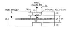
- FIG. 3Bis a cross-sectional schematic diagram illustrating generally one example of a distal portion of an imaging guidewire that combines an acousto-optic FBG sensor 100 with an photoacoustic transducer 325 .
- photoacoustic transducer 325includes a blazed Bragg grating 330 .
- blazed Bragg grating 330is implemented in the strain sensitive region of the FBG sensor 100 , between FBGs 110 A-B, however, this is not a requirement.
- the blazed Bragg grating 330includes obliquely impressed index changes that are at a nonperpendicular angle to the longitudinal axis of the optical fiber 105 .
- a standard unblazed FBGpartially or substantially fully reflects optical energy of a specific wavelength traveling down the axis of the fiber core 115 of optical fiber 105 back up the same axis.
- Blazed FBG 330reflects this optical energy away from the longitudinal axis of the optical fiber 105 .
- the optical energywill leave blazed FBG 330 substantially normal (i.e., perpendicular) to the longitudinal axis of the optical fiber 105 .
- an optically absorptive photoacoustic material 335also referred to as a “photoacoustic” material is placed on the surface of optical fiber 105 .
- the optically absorptive photoacoustic material 335is positioned, with respect to the blazed grating 330 , so as to receive the optical energy leaving the blazed grating. The received optical energy is converted in the optically absorptive material 335 to heat that expands the optically absorptive photoacoustic material 335 .
- the optically absorptive photoacoustic material 335is selected to expand and contract quickly enough to create and transmit an ultrasound or other acoustic wave that is used for acoustic imaging of the region of interest about the distal tip (or other desired portion) of the imaging guidewire.
- the optically absorptive photoacoustic material 335is the same material as the acoustic matching material 305 discussed above.
- FIG. 4is a cross-sectional schematic diagram illustrating generally one example of the operation of photoacoustic transducer 325 using a blazed Bragg grating 330 .
- Optical energy of a specific wavelength, ⁇ 1travels down the fiber core 115 of optical fiber 105 and is reflected out of the optical fiber 105 by blazed grating 330 .
- the outwardly reflected optical energyimpinges on the photoacoustic material 335 .
- the photoacoustic material 335then generates a responsive acoustic impulse that radiates away from the photoacoustic material 335 toward nearby biological or other material to be imaged.
- Acoustic energy of a specific frequencyis generated by optically irradiating the photoacoustic material 335 at a pulse rate equal to the desired acoustic frequency.
- the photoacoustic material 335has a thickness 340 (in the direction in which optical energy is received from blazed Bragg grating 330 ) that is selected to increase the efficiency of emission of acoustic energy.
- thickness 340is selected to be about 1 ⁇ 4 the acoustic wavelength of the material at the desired acoustic transmission/reception frequency. This improves the generation of acoustic energy by the photoacoustic material.
- the photoacoustic materialis of a thickness 300 that is about 1 ⁇ 4 the acoustic wavelength of the material at the desired acoustic transmission/reception frequency
- the corresponding glass-based optical fiber sensing region resonant thickness 300is about 1 ⁇ 2 the acoustic wavelength of that material at the desired acoustic transmission/reception frequency. This further improves the generation of acoustic energy by the photoacoustic material and reception of the acoustic energy by the optical fiber sensing region.
- light reflected from the blazed gratingexcites the photoacoustic material in such a way that the optical energy is efficiently converted to substantially the same acoustic frequency for which the FBG sensor is designed.
- the blazed FBG and photoacoustic material, in conjunction with the aforementioned FBG sensor,provide both a transmit transducer and a receive sensor, which are harmonized to create an efficient unified optical-to-acoustic-to-optical transmit/receive device.
- the optical wavelength for sensingis different from that used for transmission.
- the optical transmit/receive frequenciesare sufficiently different that the reception is not adversely affected by the transmission, and vice-versa.
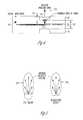
- FIG. 5is a schematic diagram comparing an expected angular sensitivity pattern of an exemplary blazed FBG optical-to-acoustic and acoustic-to-optical combined device 500 to that of a piezoelectric transducer 505 .
- the optical-to-acoustic-to-optical sensor assembly 500is expected to be capable of operating over a specific angular range that is substantially similar to that of the piezoelectric transducer 505 of similar dimensions. Therefore, in one example, the blazed FBG optical-to-acoustic and acoustic-to-optical combined device 500 is capable of using conventional intravascular ultrasound (“IVUS”) techniques.
- IVUSintravascular ultrasound
- FIG. 6is a schematic diagram illustrating generally one technique of generating an image of a vessel wall 600 by rotating the blazed FBG optical-to-acoustic and acoustic-to-optical combined transducer 500 and displaying the resultant series of radial image lines to create a radial image.
- phased array magesare created using a substantially stationary (i.e., non-rotating) set of multiple FBG sensors, such as FBG sensors 500 A-J.
- FIG. 7is a schematic diagram that illustrates generally one such phased array example, in which the signal to/from each array transducer 500 A-J is combined with the signals from one or more other transducers 500 A-J to synthesize a radial image line.
- other image linesare similarly synthesized from the array signals, such as by using specific changes in the signal processing used to combine these signals.
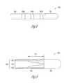
- FIG. 8is a schematic diagram that illustrates generally an example of a side view of a distal portion 800 of an imaging guidewire 805 or other elongate catheter (in one example, the guidewire 805 is capable of being used for introducing and/or guiding a catheter or other medical instrument, e.g., over the guidewire 805 ).
- the distal portion 800 of the imaging guidewire 805includes one or more imaging windows 810 A, 810 B, . . . , 810 N located slightly or considerably proximal to a distal tip 815 of the guidewire 805 .
- Each imaging window 810includes one or more optical-to-acoustic transducers 325 and a corresponding one or more separate or integrated acoustic-to-optical FBG sensors 100 .
- each imaging window 810includes an array of blazed FBG optical-to-acoustic and acoustic-to-optical combined transducers 500 (such as illustrated in FIG. 7 ) located slightly proximal to distal tip 815 of guidewire 805 having mechanical properties that allow the guidewire 805 to be guided through a vascular or other lumen.
- the different imaging windows 810 A, 810 B, . . . , 810 Nare designed for different optical wavelengths, such that individual windows can be easily addressed by changing the optical wavelength being communicated through fiber core 115 .
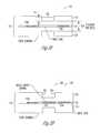
- FIG. 9is a schematic diagram that illustrates generally one example of a cross-sectional side view of a distal portion 900 of another guidewire 905 .
- the guide-wire 905includes a solid metal or other core 910 that tapers down in diameter (e.g., from an outer diameter of about 0.011 inches) at a suitable distance 915 (e.g., about 50 cm) from the distal tip 920 , to which the tapered core 910 is attached.
- optical fibers 925are distributed around the outer circumference of the guidewire core 910 , and attached to the distal tip 920 .
- the optical fibers 925are at least partially embedded in a polymer matrix or other binder material that bonds the optical fibers 925 to the guidewire core 910 and/or the distal tip 920 .
- the binder materialmay also contribute to the torsion response of the resulting guidewire assembly 905 .
- the optical fibers 925 and binder materialis overcoated with a polymer or other coating 930 , such as for providing abrasion resistance, optical fiber protection, and/or friction control.
- the composite structure of the distal region 900 of the guidewire 905provides, among other things, flexibility and rotational stiffness, thereby allowing the guidewire 905 to be maneuvered to an imaging region of interest within a vascular or any other lumen.
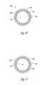
- FIG. 10is a schematic diagram that illustrates generally one example of a cross-sectional end view of a proximal portion 1000 of guidewire 905 , which includes guidewire core 910 , optical fibers 925 , binder material 1005 , and outer coating 930 .
- the diameter of the core 910is about 11/1000 inch
- the diameter of the optical fibers 925is about (1.25)/1000 inch
- the optional outer coating 930is about (0.25)/1000 inch thick.
- FIG. 11is a schematic diagram that illustrates generally one example of a cross-sectional end view of distal portion 900 of guidewire 905 , e.g., adjacent to distal tip 920 .
- the diameter of core 910has tapered down to about (1.5)/1000 inch, circumferentially surrounded by a void 1100 of about the same diameter (e.g., about 11/1000 inch) as the core 910 near the proximal end 100 of the guidewire 905 .
- the optical fibers 925are circumferentially disposed in the binder material 1005 around the void 1100 . Binder material 1005 provides structural support.
- Optical fibers 925are optionally overlaid with the outer coating 930 .
- FIG. 12is a schematic diagram that illustrates generally one example of a cross-sectional side view of a distal portion 900 of a guidewire 905 .
- at least one metallic or other bulkhead 1200is provided along the tapered portion of the guidewire core 910 .
- the optical fibers 925 and binder 1005are attached to a proximal side of the bulkhead 1200 near its circumferential perimeter.
- a distal side of the bulkhead 1200is attached, near its circumferential perimeter, to a coil winding 1205 that extends further, in the distal direction, to a ball or other distal tip 920 of the guidewire 905 .
- the guidewire 905is assembled, such as by binding the optical fibers 925 to the core 910 and distal tip 920 or bulkhead 1200 , and optionally coating the guidewire 905 .
- the optoacoustic transducer(s)are then integrated into the guidewire assembly 905 , such as by grinding one or more grooves in the guidewire at the locations of the optoacoustic transducer windows 810 .
- the depth of these groove(s) in the optical fiber(s) 925defines the resonant structure(s) of the optoacoustic transducer(s).
- the FBGsadded to one or more portions of the optical fiber 925 within such windows 810 .
- the FBGsare created using an optical process in which the portion of the optical fiber 925 is exposed to a carefully controlled pattern of UV radiation that defines the Bragg gratings.
- a photoacoustic materialis deposited or otherwise added in the transducer windows 810 over respective Bragg gratings.
- a suitable photoacoustic materialis pigmented polydimethylsiloxane (PDMS), such as a mixture of PDMS, carbon black, and toluene.
- PDMSpolydimethylsiloxane
- the FBGsare advantageously constructed after the major elements of the guidewire are mechanically assembled into the guidewire assembly 905 .
- the guidewire 905allows for over-the-guidewire or other insertion of a catheter at the proximal end of the guidewire. Therefore, in such an example, the guidewire 905 (including any proximal end interface) has an outer diameter that is less than or equal to the inner diameter (e.g., 0.014 inches) of a catheter to allow the catheter with a similarly-sized inner diameter to travel over the guidewire 905 .
- FIGS. 13A and 13Bprovide illustrative examples of an optical coupler that easily engages and disengages guidewire 905 . Among other things, this facilitates over-the-guidewire catheter insertion, and viewing an imaging region either before, during, or after such a catheter is inserted over-the-guidewire.
- FIG. 13Ais a cross-sectional schematic diagram illustrating generally one example of a proximal portion 1300 of guidewire 905 , which is communicatively coupled to an instrumentation/control interface via an optical coupler 1305 .
- proximal portion 1300 of guidewire 905is received within a receptacle 1310 portion of optical coupler 1305 , and includes one or more blazed FBGs 1315 to couple light into and/or out of one or more respective optical fibers 925 of guidewire 905 .
- Optical coupler 1305includes one or more corresponding blazed FBGs 1320 to couple light into and/or out of one or more respective optical fibers 1325 of optical coupler 1305 .
- FIG. 13Ais a cross-sectional schematic diagram illustrating generally one example of a proximal portion 1300 of guidewire 905 , which is communicatively coupled to an instrumentation/control interface via an optical coupler 1305 .
- proximal portion 1300 of guidewire 905
- the FBGs 1320 of optical coupler 1305are located substantially adjacent to corresponding FBGs 1315 of guidewire 905 when guidewire 905 is engaged within receptacle 1310 of optical coupler 1305 .
- FIG. 13Aillustrates a multiple-fiber embodiment of guidewire 905
- the illustrated techniques for coupling to an instrumentation/control interfaceare also applicable to a guidewire that includes a single optical fiber.
- FIG. 13Bis a cross-sectional schematic diagram illustrating generally a further example of a proximal portion 1300 of guidewire 905 that is communicatively coupled to an instrumentation/control interface using an optical coupler 1305 .
- at least one optical fiber 925transmits light at a different wavelength from that at which it receives light. Therefore, such an optical fiber 925 includes two separate blazed FBGs that couple light into and out of each such optical fiber 925 .
- optical fiber 925 Aincludes a first blazed FBG 1315 A operating at the transmit wavelength, and a second blazed FBG 1330 A operating at the receive wavelength.
- Optical coupler 1305includes a corresponding first blazed FBG 1320 A operating at the transmit wavelength and a second blazed FBG 1335 A operating at the receive wavelength.
- blazed FBGs 1320 A and 1315 Aare located substantially adjacent to each other
- blazed FBGs 1335 A and 1330 Aare located substantially adjacent to each other.
- optical fiber 925 B and optical coupler 1305respectively include substantially adjacent transmit FBGs 1315 B and 1320 B and substantially adjacent receive FBGs 1330 B and 1335 B.
- optical coupler 1305For additional optoacoustic transducer windows 810 at or near the distal portion 900 or elsewhere along guidewire 905 , corresponding additional blazed FBGs may similarly be included on optical coupler 1305 at the appropriate wavelength for transmitting and/or receiving optical energy with respect to such additional optoacoustic transducer windows 810 .
- optical coupler 1305need not be located exactly at the proximal end of the guidewire 905 , but may instead be located anywhere near the proximal portion 1300 of the guidewire 905 or even further toward the distal portion 900 of the guidewire 905 .
- alignment of the optical coupler 1305 to guidewire 905need not be limited to butting guidewire 905 into receptacle 1310 of optical coupler 1305 ; any other alignment mechanism and/or technique is also included.
- FIG. 14Ais a block diagram illustrating generally one example of the imaging guidewire 905 and associated interface components.
- the block diagram of FIG. 14Aincludes the imaging guidewire 905 , which is coupled by optical coupler 1305 to an optoelectronics module 1400 .
- the optoelectronics module 1400is coupled to an image processing module 1405 and a user interface 1410 that includes a display providing a viewable still and/or video image of the imaging region near one or more acoustic-to-optical transducers using the acoustically-modulated optical signal received therefrom.
- the system 1415 illustrated in the block diagram of FIG. 14Auses an image processing module 1405 and a user interface 1410 that are substantially similar to existing acoustic imaging systems.
- FIG. 14Bis a block diagram illustrating generally another example of the imaging guidewire 905 and associated interface components.
- the associated interface componentsinclude a tissue (and plaque) characterization module 1420 and an image enhancement module 1425 .
- an input of tissue characterization module 1420is coupled to an output from optoelectronics module 1400 .
- An output of tissue characterization module 1420is coupled to at least one of user interface 1410 or an input of image enhancement module 1425 .
- An output of image enhancement module 1425is coupled to user interface 1410 , such as through image processing module 1405 .
- tissue characterization module 1420processes a signal output from optoelectronics module 1400 .
- signal processingassists in distinguishing plaque from nearby vascular tissue.
- plaquecan be conceptualized as including, among other things, cholesterol, thrombus, and loose connective tissue that build up within a blood vessel wall.
- Calcified plaquetypically reflects ultrasound better than the nearby vascular tissue, which results in high amplitude echoes.
- Soft plaquesproduce weaker and more texturally homogeneous echoes.
- tissue characterization signal processingmay include performing a spectral analysis that examines the energy of the returned ultrasound signal at various frequencies.
- a plaque depositwill typically have a different spectral signature than nearby vascular tissue without such plaque, allowing discrimination therebetween.
- Such signal processingmay additionally or alternatively include statistical processing (e.g., averaging, filtering, or the like) of the returned ultrasound signal in the time domain.
- Other signal processing techniques known in the art of tissue characterizationmay also be applied.
- the spatial distribution of the processed returned ultrasound signalis provided to image enhancement module 1425 , which provides resulting image enhancement information to image processing module 1405 .
- image enhancement module 1425provides information to user interface 1410 that results in a displaying plaque deposits in a visually different manner (e.g., by assigning plaque deposits a discernable color on the image) than other portions of the image.
- Other image enhancement techniques known in the art of imagingmay also be applied.
- similar techniquesare used for discriminating between vulnerable plaque and other plaque, and enhancing the displayed image provide a visual indicator assisting the user in discriminating between vulnerable and other plaque.
- the opto-electronics module 1400may include one or more lasers and fiber optic elements.
- a first laseris used for providing light to the guidewire 905 for the transmitted ultrasound
- a separate second laseris used for providing light to the guidewire 905 for being modulated by the received ultrasound.
- a fiber optic multiplexercouples each channel (associated with a particular one of the guidewire's optical fibers 925 ) to the transmit and receive lasers and associated optics. This reduces system complexity and costs.
- the sharing of transmit and receive components by multiple guidewire channelsis possible at least in part because the acoustic image is acquired over a relatively short distance (e.g., millimeters).
- the speed of ultrasound in a human or animal bodyis slow enough to allow for a large number of transmit/receive cycles to be performed during the time period of one image frame. For example, at an image depth (range) of about 2 cm, it will take ultrasonic energy approximately 26 microseconds to travel from the sensor to the range limit, and back. In one such example, therefore, an about 30 microseconds transmit/receive (T/R) cycle is used. In the approximately 30 milliseconds allotted to a single image frame, up to 1,000 T/R cycles can be carried out.
- T/Rtransmit/receive
- such a large number of T/R cycles per frameallows the system to operate as a phased array even though each sensor is accessed in sequence.
- Such sequential access of the photoacoustic sensors in the guidewirepermits (but does not require) the use of one set of T/R opto-electronics in conjunction with a sequentially operated optical multiplexer.
- the systemis operated to provide a 3-D visual image that permits the viewing of a desired volume of the patient's anatomy or other imaging region of interest. This allows the physician to quickly see the detailed spatial arrangement of structures, such as lesions, with respect to other anatomy.
- such an embodimentallows substantially simultaneous images to be obtained from all 10 transducer windows at of each optical fiber at video rates (e.g., at about 30 frames per second for each transducer window).
- Thisallows real-time volumetric data acquisition, which offers a distinct advantage over other imaging techniques.
- real-time volumetric data acquisitionallows real-time 3-D vascular imaging, including visualization of the topology of a blood vessel wall, the extent and precise location of plaque deposits, and, therefore, the ability to identify vulnerable plaque.
- FIG. 15is a cross-sectional schematic diagram illustrating generally one example of an alternate acoustic-to-optical transducer 1500 , which in this example is integrated into an optical fiber 105 , including fiber core 105 and fiber cladding 120 and covered by coating 930 .
- transducer 1500includes a blazed FBG 330 in core 115 , a translucent deformable (or empty) region 1505 in cladding 120 , and an acoustically-deformable light-reflective surface region 1510 overlaying at least a portion of translucent region 1505 .
- acoustic-to-optical transducer 1500is fabricated in a window 810 of an imaging guidewire 805 along with an optical-to-acoustic transducer 325 , which generates acoustic energy in a nearby imaging region of interest to be received by acoustic-to-optical transducer 1500 .
- FIG. 16is a cross-sectional schematic diagram illustrating generally one example of acoustic-to-optical transducer 1500 in operation.
- FBG 330receives light from a proximal end of fiber core 105 , and directs the received light outward through translucent region 1505 such that the light impinges upon, and is reflected by, reflective region 1510 . At least some of the reflected light is received at FBG 330 and directed back toward the proximal end of fiber core 105 .
- reflective region 1510deflects in response to acoustic energy received from the nearby imaging region of interest as a result of insonification by a nearby optical-to-acoustic transducer 325 .
- the deflection of reflective region 1510modulates the distance that the light travels between FBG 330 and reflective region 1510 .
- the resulting change in wavelength or intensityis monitored by interface optoelectronics coupled to a proximal end of optical fiber 105 , such as using the above-described components and techniques.
- acoustic-to-optical transducer 1500need only include a single FBG (e.g., blazed FBG 330 ). Moreover, acoustic-to-optical transducer 1500 need not rely on the Poisson effect in which received acoustic energy “squeezes” in a first direction, thereby modulating an interferometric strain-sensing distance in a second direction that is normal to the first direction. An acoustic-to-optical transducer using the Poisson effect typically suffers from some attenuation in translating the mechanical force from the first direction to the orthogonal second direction. As illustrated in FIG.
- the acoustic-to-optical transducer 1500detects a modulating distance that is in the substantially the same direction as the received acoustic energy. Moreover, because region 1510 is reflective, a given deflection results in a modulation of twice the number of wavelengths of light in that deflection distance. This further increases the sensitivity of acoustic-to-optical transducer 1500 .
- region 1505is filled with a transparent polymer to allow optical energy to pass through.
- region 1505has a thickness 1515 that is 1 ⁇ 4-wave resonant with the received acoustic pressure wave.
- the resonance of the polymer-filled region 1505serves to increase the motion of the reflective region 1510 over that which would occur if region 1505 were formed of glass.
- the polymer-filled region 1505includes an acoustic impedance that is close to that of water and, therefore, human or animal tissue.
- intravascular imaginge.g., for viewing and/or identifying vulnerable plaque
- the present systems, devices, and methodsare also applicable to imaging any other body part.
- guidewire or other elongate body as discussed abovecould be inserted into a biopsy needle, laparoscopic device, or any other lumen or cavity for performing imaging.
- imagingneed not involve insertion of an elongate body into a lumen, for example, an imaging apparatus could alternatively be wrapped around a portion of a region to be imaged.
- this technologycan be used to process the Doppler shift in acoustic frequency to image blood flow.
- the operationwould be similar to that described above, however, this would increase the length of the transmitted acoustic signal, and would use known Doppler signal processing in the image processing portion of the control electronics.
- the transmitted acoustic signalcan be lengthened by repeatedly pulsing the transmit optical energy at the same rate as the desired acoustic frequency.
Landscapes
- Health & Medical Sciences (AREA)
- Life Sciences & Earth Sciences (AREA)
- Physics & Mathematics (AREA)
- General Health & Medical Sciences (AREA)
- Surgery (AREA)
- Pathology (AREA)
- Engineering & Computer Science (AREA)
- Biomedical Technology (AREA)
- Heart & Thoracic Surgery (AREA)
- Medical Informatics (AREA)
- Molecular Biology (AREA)
- Animal Behavior & Ethology (AREA)
- Biophysics (AREA)
- Public Health (AREA)
- Veterinary Medicine (AREA)
- General Physics & Mathematics (AREA)
- Acoustics & Sound (AREA)
- Vascular Medicine (AREA)
- Nuclear Medicine, Radiotherapy & Molecular Imaging (AREA)
- Radiology & Medical Imaging (AREA)
- Optics & Photonics (AREA)
- Analytical Chemistry (AREA)
- Biochemistry (AREA)
- Immunology (AREA)
- Chemical & Material Sciences (AREA)
- Cardiology (AREA)
- Physiology (AREA)
- Ultra Sonic Daignosis Equipment (AREA)
- Investigating Or Analysing Materials By Optical Means (AREA)
Abstract
Description
Claims (27)
Priority Applications (4)
| Application Number | Priority Date | Filing Date | Title |
|---|---|---|---|
| US13/285,551US8391652B2 (en) | 2002-10-07 | 2011-10-31 | Systems and methods for minimally-invasive optical-acoustic imaging |
| US13/779,985US8731340B2 (en) | 2002-10-07 | 2013-02-28 | Systems and methods for minimally-invasive optical-acoustic imaging |
| US14/280,327US9192307B2 (en) | 2002-10-07 | 2014-05-16 | Systems and methods for minimally-invasive optical-acoustic imaging |
| US14/836,705US9339192B2 (en) | 2002-10-07 | 2015-08-26 | Systems and methods for minimally-invasive optical-acoustic imaging |
Applications Claiming Priority (5)
| Application Number | Priority Date | Filing Date | Title |
|---|---|---|---|
| US10/266,082US7245789B2 (en) | 2002-10-07 | 2002-10-07 | Systems and methods for minimally-invasive optical-acoustic imaging |
| US11/674,568US7447388B2 (en) | 2002-10-07 | 2007-02-13 | Systems and methods for minimally-invasive optical-acoustic imaging |
| US12/263,978US7660492B2 (en) | 2002-10-07 | 2008-11-03 | Systems and methods for minimally-invasive optical-acoustic imaging |
| US12/701,228US8059923B2 (en) | 2002-10-07 | 2010-02-05 | Systems and methods for minimally-invasive optical-acoustic imaging |
| US13/285,551US8391652B2 (en) | 2002-10-07 | 2011-10-31 | Systems and methods for minimally-invasive optical-acoustic imaging |
Related Parent Applications (1)
| Application Number | Title | Priority Date | Filing Date |
|---|---|---|---|
| US12/701,228ContinuationUS8059923B2 (en) | 2002-10-07 | 2010-02-05 | Systems and methods for minimally-invasive optical-acoustic imaging |
Related Child Applications (1)
| Application Number | Title | Priority Date | Filing Date |
|---|---|---|---|
| US13/779,985ContinuationUS8731340B2 (en) | 2002-10-07 | 2013-02-28 | Systems and methods for minimally-invasive optical-acoustic imaging |
Publications (2)
| Publication Number | Publication Date |
|---|---|
| US20120108943A1 US20120108943A1 (en) | 2012-05-03 |
| US8391652B2true US8391652B2 (en) | 2013-03-05 |
Family
ID=32042596
Family Applications (8)
| Application Number | Title | Priority Date | Filing Date |
|---|---|---|---|
| US10/266,082Expired - LifetimeUS7245789B2 (en) | 2002-10-07 | 2002-10-07 | Systems and methods for minimally-invasive optical-acoustic imaging |
| US11/674,568Expired - LifetimeUS7447388B2 (en) | 2002-10-07 | 2007-02-13 | Systems and methods for minimally-invasive optical-acoustic imaging |
| US12/263,978Expired - Fee RelatedUS7660492B2 (en) | 2002-10-07 | 2008-11-03 | Systems and methods for minimally-invasive optical-acoustic imaging |
| US12/701,228Expired - Fee RelatedUS8059923B2 (en) | 2002-10-07 | 2010-02-05 | Systems and methods for minimally-invasive optical-acoustic imaging |
| US13/285,551Expired - Fee RelatedUS8391652B2 (en) | 2002-10-07 | 2011-10-31 | Systems and methods for minimally-invasive optical-acoustic imaging |
| US13/779,985Expired - LifetimeUS8731340B2 (en) | 2002-10-07 | 2013-02-28 | Systems and methods for minimally-invasive optical-acoustic imaging |
| US14/280,327Expired - Fee RelatedUS9192307B2 (en) | 2002-10-07 | 2014-05-16 | Systems and methods for minimally-invasive optical-acoustic imaging |
| US14/836,705Expired - Fee RelatedUS9339192B2 (en) | 2002-10-07 | 2015-08-26 | Systems and methods for minimally-invasive optical-acoustic imaging |
Family Applications Before (4)
| Application Number | Title | Priority Date | Filing Date |
|---|---|---|---|
| US10/266,082Expired - LifetimeUS7245789B2 (en) | 2002-10-07 | 2002-10-07 | Systems and methods for minimally-invasive optical-acoustic imaging |
| US11/674,568Expired - LifetimeUS7447388B2 (en) | 2002-10-07 | 2007-02-13 | Systems and methods for minimally-invasive optical-acoustic imaging |
| US12/263,978Expired - Fee RelatedUS7660492B2 (en) | 2002-10-07 | 2008-11-03 | Systems and methods for minimally-invasive optical-acoustic imaging |
| US12/701,228Expired - Fee RelatedUS8059923B2 (en) | 2002-10-07 | 2010-02-05 | Systems and methods for minimally-invasive optical-acoustic imaging |
Family Applications After (3)
| Application Number | Title | Priority Date | Filing Date |
|---|---|---|---|
| US13/779,985Expired - LifetimeUS8731340B2 (en) | 2002-10-07 | 2013-02-28 | Systems and methods for minimally-invasive optical-acoustic imaging |
| US14/280,327Expired - Fee RelatedUS9192307B2 (en) | 2002-10-07 | 2014-05-16 | Systems and methods for minimally-invasive optical-acoustic imaging |
| US14/836,705Expired - Fee RelatedUS9339192B2 (en) | 2002-10-07 | 2015-08-26 | Systems and methods for minimally-invasive optical-acoustic imaging |
Country Status (6)
| Country | Link |
|---|---|
| US (8) | US7245789B2 (en) |
| EP (1) | EP1555942B8 (en) |
| JP (2) | JP4733982B2 (en) |
| AU (1) | AU2003299911A1 (en) |
| CA (1) | CA2501048A1 (en) |
| WO (1) | WO2004032746A2 (en) |
Cited By (6)
| Publication number | Priority date | Publication date | Assignee | Title |
|---|---|---|---|---|
| US20080119739A1 (en)* | 1998-03-05 | 2008-05-22 | Vascular Imaging Corporation | Optical-acoustic imaging device |
| US20100087732A1 (en)* | 2008-10-02 | 2010-04-08 | Vascular Imaging Corporation | Optical ultrasound receiver |
| US8701494B1 (en)* | 2008-07-17 | 2014-04-22 | Optech Ventures, Llc | Apparatus and method for damage location and identification in structures |
| US8731340B2 (en) | 2002-10-07 | 2014-05-20 | Vascular Imaging Corporation | Systems and methods for minimally-invasive optical-acoustic imaging |
| US8861908B2 (en) | 2005-11-22 | 2014-10-14 | Vascular Imaging Corporation | Optical imaging probe |
| US10548489B2 (en) | 2014-10-31 | 2020-02-04 | Lake Region Medical, Inc. | Fiber Bragg grating multi-point pressure sensing guidewire with birefringent component |
Families Citing this family (240)
| Publication number | Priority date | Publication date | Assignee | Title |
|---|---|---|---|---|
| US20080154257A1 (en)* | 2006-12-22 | 2008-06-26 | Shiva Sharareh | Real-time optoacoustic monitoring with electophysiologic catheters |
| US20080207197A1 (en)* | 1997-07-30 | 2008-08-28 | Steven Tischer | Apparatus, method, and computer-readable medium for interfacing devices with communications networks |
| US7068867B2 (en)* | 2003-01-02 | 2006-06-27 | Glucon Medical Ltd | Ultrasonic position indicator |
| US8282561B2 (en)* | 2003-05-23 | 2012-10-09 | Arizona Board Of Regents | Piezo micro-markers for ultrasound medical diagnostics |
| US7397987B2 (en)* | 2004-05-06 | 2008-07-08 | California Institute Of Technology | Resonantly enhanced grating coupler |
| WO2006001071A1 (en)* | 2004-06-25 | 2006-01-05 | Neubrex Co., Ltd. | Distributed optical fiber sensor |
| US20080114254A1 (en)* | 2004-09-19 | 2008-05-15 | Bioscan Ltd. | Intravascular Ultrasound Imaging Device |
| US8048080B2 (en) | 2004-10-15 | 2011-11-01 | Baxano, Inc. | Flexible tissue rasp |
| US7738969B2 (en) | 2004-10-15 | 2010-06-15 | Baxano, Inc. | Devices and methods for selective surgical removal of tissue |
| US7887538B2 (en) | 2005-10-15 | 2011-02-15 | Baxano, Inc. | Methods and apparatus for tissue modification |
| US7959577B2 (en)* | 2007-09-06 | 2011-06-14 | Baxano, Inc. | Method, system, and apparatus for neural localization |
| US8613745B2 (en) | 2004-10-15 | 2013-12-24 | Baxano Surgical, Inc. | Methods, systems and devices for carpal tunnel release |
| US20070213734A1 (en)* | 2006-03-13 | 2007-09-13 | Bleich Jeffery L | Tissue modification barrier devices and methods |
| US20110190772A1 (en) | 2004-10-15 | 2011-08-04 | Vahid Saadat | Powered tissue modification devices and methods |
| US7938830B2 (en) | 2004-10-15 | 2011-05-10 | Baxano, Inc. | Powered tissue modification devices and methods |
| US20100331883A1 (en) | 2004-10-15 | 2010-12-30 | Schmitz Gregory P | Access and tissue modification systems and methods |
| US20080103504A1 (en)* | 2006-10-30 | 2008-05-01 | Schmitz Gregory P | Percutaneous spinal stenosis treatment |
| JP5243034B2 (en) | 2004-10-15 | 2013-07-24 | バクサノ,インク. | Tissue removal device |
| US7578819B2 (en) | 2005-05-16 | 2009-08-25 | Baxano, Inc. | Spinal access and neural localization |
| US8257356B2 (en) | 2004-10-15 | 2012-09-04 | Baxano, Inc. | Guidewire exchange systems to treat spinal stenosis |
| US8430881B2 (en)* | 2004-10-15 | 2013-04-30 | Baxano, Inc. | Mechanical tissue modification devices and methods |
| US7963915B2 (en) | 2004-10-15 | 2011-06-21 | Baxano, Inc. | Devices and methods for tissue access |
| US9247952B2 (en) | 2004-10-15 | 2016-02-02 | Amendia, Inc. | Devices and methods for tissue access |
| US9101386B2 (en) | 2004-10-15 | 2015-08-11 | Amendia, Inc. | Devices and methods for treating tissue |
| US8221397B2 (en) | 2004-10-15 | 2012-07-17 | Baxano, Inc. | Devices and methods for tissue modification |
| US8062300B2 (en) | 2006-05-04 | 2011-11-22 | Baxano, Inc. | Tissue removal with at least partially flexible devices |
| US7857813B2 (en) | 2006-08-29 | 2010-12-28 | Baxano, Inc. | Tissue access guidewire system and method |
| US7417740B2 (en)* | 2004-11-12 | 2008-08-26 | Medeikon Corporation | Single trace multi-channel low coherence interferometric sensor |
| WO2006061829A1 (en)* | 2004-12-06 | 2006-06-15 | Glucon Inc. | Photoacoustic intravascular probe |
| US20080051812A1 (en)* | 2006-08-01 | 2008-02-28 | Baxano, Inc. | Multi-Wire Tissue Cutter |
| US8366712B2 (en) | 2005-10-15 | 2013-02-05 | Baxano, Inc. | Multiple pathways for spinal nerve root decompression from a single access point |
| US8092456B2 (en) | 2005-10-15 | 2012-01-10 | Baxano, Inc. | Multiple pathways for spinal nerve root decompression from a single access point |
| US8062298B2 (en) | 2005-10-15 | 2011-11-22 | Baxano, Inc. | Flexible tissue removal devices and methods |
| US20070129625A1 (en)* | 2005-11-21 | 2007-06-07 | Boston Scientific Scimed Systems, Inc. | Systems and methods for detecting the presence of abnormalities in a medical image |
| US7717618B2 (en)* | 2005-12-30 | 2010-05-18 | Optech Ventures, Llc | Apparatus and method for high resolution temperature measurement and for hyperthermia therapy |
| US7750536B2 (en) | 2006-03-02 | 2010-07-06 | Visualsonics Inc. | High frequency ultrasonic transducer and matching layer comprising cyanoacrylate |
| US20070291275A1 (en)* | 2006-06-16 | 2007-12-20 | Prescient Medical, Inc. | Side-viewing optical acoustic sensors and their use in intravascular diagnostic probes |
| US20080013909A1 (en)* | 2006-07-14 | 2008-01-17 | Tenvera, Inc. | Modular Optical Fiber Network Interface |
| US20080013956A1 (en)* | 2006-07-14 | 2008-01-17 | Tenvera, Inc. | Provisioning of Services Via an Optical Fiber Network |
| US20080013957A1 (en)* | 2006-07-14 | 2008-01-17 | Tenvera, Inc. | Service Aggregation Gateway |
| US20080013907A1 (en)* | 2006-07-14 | 2008-01-17 | Tenvera, Inc. | Optical Fiber Blowing Device and Method |
| US20080011990A1 (en)* | 2006-07-14 | 2008-01-17 | Tenvera, Inc. | Installation of Fiber Optic Cables |
| US20080011514A1 (en)* | 2006-07-14 | 2008-01-17 | Tenvera, Inc. | Optical Fiber Distribution Apparatus and Method |
| JP2008036153A (en)* | 2006-08-07 | 2008-02-21 | Hamamatsu Photonics Kk | Light irradiation apparatus |
| US9867530B2 (en) | 2006-08-14 | 2018-01-16 | Volcano Corporation | Telescopic side port catheter device with imaging system and method for accessing side branch occlusions |
| US8554024B2 (en) | 2006-10-25 | 2013-10-08 | Lxdata Inc. | Tilted grating sensor |
| BRPI0719142A8 (en)* | 2006-11-21 | 2015-10-13 | Koninklijke Philips Electronics Nv | SYSTEM AND METHOD FOR IMAGE FORMATION OF PROSTATE TISSUE IN AN ANATOMICAL STRUCTURE |
| EP2241274B1 (en)* | 2006-12-07 | 2012-02-01 | Baxano, Inc. | Tissue removal devices |
| ATE526882T1 (en)* | 2006-12-19 | 2011-10-15 | Koninkl Philips Electronics Nv | COMBINED PHOTOACOUSTIC AND ULTRASONIC DISPLAY SYSTEM |
| JP4345825B2 (en)* | 2007-02-23 | 2009-10-14 | 株式会社デンソー | In-vehicle emergency call device |
| JP5134277B2 (en)* | 2007-03-30 | 2013-01-30 | 三菱重工業株式会社 | Ultrasonic inspection equipment |
| US8347738B2 (en)* | 2007-05-09 | 2013-01-08 | The Board Of Trustees Of The Leland Stanford Junior University | Sensors and control for an interventional catheter |
| WO2009009802A1 (en) | 2007-07-12 | 2009-01-15 | Volcano Corporation | Oct-ivus catheter for concurrent luminal imaging |
| US9596993B2 (en) | 2007-07-12 | 2017-03-21 | Volcano Corporation | Automatic calibration systems and methods of use |
| EP2178442B1 (en) | 2007-07-12 | 2017-09-06 | Volcano Corporation | Catheter for in vivo imaging |
| US7812960B2 (en) | 2007-10-16 | 2010-10-12 | Judd Gardner | Optical ultrasound device |
| EP3229010A3 (en) | 2007-10-25 | 2018-01-10 | Washington University in St. Louis | Confocal photoacoustic microscopy with optical lateral resolution |
| US8192436B2 (en) | 2007-12-07 | 2012-06-05 | Baxano, Inc. | Tissue modification devices |
| FR2929000B1 (en)* | 2008-03-18 | 2010-04-09 | Thales Sa | SELF-REFERENCE OPTICAL FIBER SENSOR AND ASSOCIATED SENSOR ARRAY |
| WO2009132188A1 (en)* | 2008-04-24 | 2009-10-29 | Boston Scientific Scimed, Inc. | Methods, systems, and devices for tissue characterization by spectral similarity of intravascular ultrasound signals |
| US9549713B2 (en) | 2008-04-24 | 2017-01-24 | Boston Scientific Scimed, Inc. | Methods, systems, and devices for tissue characterization and quantification using intravascular ultrasound signals |
| US8398641B2 (en) | 2008-07-01 | 2013-03-19 | Baxano, Inc. | Tissue modification devices and methods |
| US8409206B2 (en) | 2008-07-01 | 2013-04-02 | Baxano, Inc. | Tissue modification devices and methods |
| US9314253B2 (en) | 2008-07-01 | 2016-04-19 | Amendia, Inc. | Tissue modification devices and methods |
| AU2009271047B2 (en) | 2008-07-14 | 2014-04-17 | Baxano Surgical, Inc. | Tissue modification devices |
| WO2010009747A1 (en) | 2008-07-25 | 2010-01-28 | Helmholtz Zentrum München Deutsches Forschungszentrum Für Gesundheit Und Umwelt (Gmbh) | Quantitative multi-spectral opto-acoustic tomography (msot) of tissue biomarkers |
| US8583218B2 (en)* | 2008-10-31 | 2013-11-12 | Vascular Imaging Corporation | Optical imaging probe connector |
| WO2010080991A2 (en) | 2009-01-09 | 2010-07-15 | Washington University In St. Louis | Miniaturized photoacoustic imaging apparatus including a rotatable reflector |
| US9366938B1 (en) | 2009-02-17 | 2016-06-14 | Vescent Photonics, Inc. | Electro-optic beam deflector device |
| EP2405823A4 (en) | 2009-03-13 | 2012-07-04 | Baxano Inc | Flexible neural localization devices and methods |
| US8649847B1 (en)* | 2009-05-04 | 2014-02-11 | Intelligent Fiber Optic Systems, Inc. | Steerable shape sensing biopsy needle and catheter |
| US8385692B2 (en)* | 2009-05-27 | 2013-02-26 | Baker Hughes Incorporated | On-line fiber Bragg grating dithering |
| US8394102B2 (en) | 2009-06-25 | 2013-03-12 | Baxano, Inc. | Surgical tools for treatment of spinal stenosis |
| US9271654B2 (en) | 2009-06-29 | 2016-03-01 | Helmholtz Zentrum Munchen Deutsches Forschungszentrum Fur Gesundheit Und Umwelt (Gmbh) | Thermoacoustic imaging with quantitative extraction of absorption map |
| WO2011008559A1 (en) | 2009-06-29 | 2011-01-20 | University Of Massachusetts Lowell | Optical fiber pressure sensor with uniform diaphragm and method of fabricating same |
| EP2459987A1 (en)* | 2009-07-27 | 2012-06-06 | Helmholtz Zentrum München Deutsches Forschungszentrum für Gesundheit und Umwelt (GmbH) | Imaging device and method for optoacoustic imaging of small animals |
| US10238370B2 (en)* | 2009-09-18 | 2019-03-26 | Intelligent Fiber Optic Systems, Inc. | Steerable shape sensing biopsy needle |
| US8798704B2 (en) | 2009-09-24 | 2014-08-05 | Covidien Lp | Photoacoustic spectroscopy method and system to discern sepsis from shock |
| US8376955B2 (en) | 2009-09-29 | 2013-02-19 | Covidien Lp | Spectroscopic method and system for assessing tissue temperature |
| US20110144502A1 (en)* | 2009-12-15 | 2011-06-16 | Tea Time Partners, L.P. | Imaging guidewire |
| AU2011213036B2 (en)* | 2010-02-02 | 2013-11-14 | Covidien Lp | Continuous light emission photoacoustic spectroscopy |
| JP5771597B2 (en)* | 2010-03-16 | 2015-09-02 | テルモ株式会社 | Guidewire and catheter assembly |
| US9086365B2 (en) | 2010-04-09 | 2015-07-21 | Lihong Wang | Quantification of optical absorption coefficients using acoustic spectra in photoacoustic tomography |
| JP5389749B2 (en)* | 2010-06-24 | 2014-01-15 | 富士フイルム株式会社 | Biological information imaging apparatus and method |
| US20120203101A1 (en)* | 2010-07-09 | 2012-08-09 | Board Of Regents, The University Of Texas System | Methods for optoacoustic guidance and confirmation of placement of novel indwelling medical apparatus |
| US8930145B2 (en) | 2010-07-28 | 2015-01-06 | Covidien Lp | Light focusing continuous wave photoacoustic spectroscopy and its applications to patient monitoring |
| US9704473B2 (en)* | 2010-12-10 | 2017-07-11 | Palo Alto Research Center Incorporated | Variable acoustic grating based on changing acoustic impedances |
| US11141063B2 (en) | 2010-12-23 | 2021-10-12 | Philips Image Guided Therapy Corporation | Integrated system architectures and methods of use |
| US11040140B2 (en) | 2010-12-31 | 2021-06-22 | Philips Image Guided Therapy Corporation | Deep vein thrombosis therapeutic methods |
| US8997572B2 (en) | 2011-02-11 | 2015-04-07 | Washington University | Multi-focus optical-resolution photoacoustic microscopy with ultrasonic array detection |
| US9587976B2 (en) | 2011-02-17 | 2017-03-07 | University Of Massachusetts | Photoacoustic probe |
| JP5685214B2 (en)* | 2011-03-16 | 2015-03-18 | 富士フイルム株式会社 | Photoacoustic image generation apparatus and method |
| KR101782352B1 (en) | 2011-04-25 | 2017-09-29 | 한국기술교육대학교 산학협력단 | Apparatus For Measuring Operating Cable Force which applied to the Robot Manipulator Using Fiber Bragg Grating Sensor And Romote Operating Apparatus for Robot Mnipulator thereof |
| WO2012149519A1 (en) | 2011-04-29 | 2012-11-01 | Board Of Regents The University Of Texas System | Methods and apparatus for optoacoustic guidance and confirmation of placement of indwelling medical apparatus |
| US8608657B2 (en) | 2011-05-31 | 2013-12-17 | Covidien Lp | Clinical acceptance tool |
| CN103959043B (en) | 2011-05-31 | 2016-11-02 | 光学实验室成像公司 | Multimodal imaging systems, devices and methods |
| US9405078B2 (en) | 2011-08-30 | 2016-08-02 | Opsens Inc. | Method for disposable guidewire optical connection |
| US8936401B2 (en) | 2011-08-30 | 2015-01-20 | Claude Belleville | Method for disposable guidewire optical connection |
| US9360630B2 (en) | 2011-08-31 | 2016-06-07 | Volcano Corporation | Optical-electrical rotary joint and methods of use |
| AU2013212213B2 (en)* | 2012-01-23 | 2018-06-28 | Tomowave Laboratories, Inc. | Laser optoacoustic ultrasonic imaging system (LOUIS) and methods of use |
| KR101974580B1 (en)* | 2012-05-03 | 2019-05-02 | 삼성전자주식회사 | The laser-induced ultrasonic wave apparatus and the method of generating a image using the same |
| WO2013177577A2 (en) | 2012-05-25 | 2013-11-28 | Eberle Michael J | Optical fiber pressure sensor |
| US9936881B2 (en) | 2012-10-04 | 2018-04-10 | Vascular Imaging Corporation | Polarization scrambling for intra-body fiber optic sensor |
| US9292918B2 (en) | 2012-10-05 | 2016-03-22 | Volcano Corporation | Methods and systems for transforming luminal images |
| US9324141B2 (en) | 2012-10-05 | 2016-04-26 | Volcano Corporation | Removal of A-scan streaking artifact |
| US9858668B2 (en) | 2012-10-05 | 2018-01-02 | Volcano Corporation | Guidewire artifact removal in images |
| US9307926B2 (en) | 2012-10-05 | 2016-04-12 | Volcano Corporation | Automatic stent detection |
| US10568586B2 (en) | 2012-10-05 | 2020-02-25 | Volcano Corporation | Systems for indicating parameters in an imaging data set and methods of use |
| US9286673B2 (en) | 2012-10-05 | 2016-03-15 | Volcano Corporation | Systems for correcting distortions in a medical image and methods of use thereof |
| CA2887421A1 (en) | 2012-10-05 | 2014-04-10 | David Welford | Systems and methods for amplifying light |
| US9367965B2 (en) | 2012-10-05 | 2016-06-14 | Volcano Corporation | Systems and methods for generating images of tissue |
| US10070827B2 (en) | 2012-10-05 | 2018-09-11 | Volcano Corporation | Automatic image playback |
| US11272845B2 (en) | 2012-10-05 | 2022-03-15 | Philips Image Guided Therapy Corporation | System and method for instant and automatic border detection |
| US20140100454A1 (en) | 2012-10-05 | 2014-04-10 | Volcano Corporation | Methods and systems for establishing parameters for three-dimensional imaging |
| WO2014063005A1 (en) | 2012-10-18 | 2014-04-24 | Washington University | Transcranialphotoacoustic/thermoacoustic tomography brain imaging informed by adjunct image data |
| US9840734B2 (en) | 2012-10-22 | 2017-12-12 | Raindance Technologies, Inc. | Methods for analyzing DNA |
| EP2742854B1 (en) | 2012-12-11 | 2021-03-10 | iThera Medical GmbH | Handheld device and method for tomographic optoacoustic imaging of an object |
| EP2931132B1 (en) | 2012-12-13 | 2023-07-05 | Philips Image Guided Therapy Corporation | System for targeted cannulation |
| EP2941182A1 (en)* | 2012-12-14 | 2015-11-11 | Vascular Imaging Corporation | Noise subtraction for intra-body fiber optic sensor |
| EP2934310A4 (en) | 2012-12-20 | 2016-10-12 | Nathaniel J Kemp | Optical coherence tomography system that is reconfigurable between different imaging modes |
| US10942022B2 (en) | 2012-12-20 | 2021-03-09 | Philips Image Guided Therapy Corporation | Manual calibration of imaging system |
| US11406498B2 (en) | 2012-12-20 | 2022-08-09 | Philips Image Guided Therapy Corporation | Implant delivery system and implants |
| US10939826B2 (en)* | 2012-12-20 | 2021-03-09 | Philips Image Guided Therapy Corporation | Aspirating and removing biological material |
| EP2934311B1 (en) | 2012-12-20 | 2020-04-15 | Volcano Corporation | Smooth transition catheters |
| US20140180030A1 (en)* | 2012-12-20 | 2014-06-26 | Volcano Corporation | Intravascular blood pressure and velocity wire |
| WO2014113188A2 (en) | 2012-12-20 | 2014-07-24 | Jeremy Stigall | Locating intravascular images |
| US20140180069A1 (en)* | 2012-12-21 | 2014-06-26 | Volcano Corporation | Intraluminal imaging system |
| WO2014100207A1 (en)* | 2012-12-21 | 2014-06-26 | Paul Hoseit | Imaging guidewire with photoactivation capabilities |
| US20140180168A1 (en)* | 2012-12-21 | 2014-06-26 | Volcano Corporation | Guidewire with touch sensor |
| US10332228B2 (en) | 2012-12-21 | 2019-06-25 | Volcano Corporation | System and method for graphical processing of medical data |
| US20140200438A1 (en)* | 2012-12-21 | 2014-07-17 | Volcano Corporation | Intraluminal imaging system |
| EP2934323A4 (en) | 2012-12-21 | 2016-08-17 | Andrew Hancock | SYSTEM AND METHOD FOR MULTIPLE PROCESSING OF IMAGE SIGNALS |
| JP2016506270A (en)* | 2012-12-21 | 2016-03-03 | デイビッド アンダーソン, | Multi-sensor device |
| US9612105B2 (en) | 2012-12-21 | 2017-04-04 | Volcano Corporation | Polarization sensitive optical coherence tomography system |
| US20140180316A1 (en)* | 2012-12-21 | 2014-06-26 | Volcano Corporation | Imaging and removing biological material |
| JP2016507892A (en) | 2012-12-21 | 2016-03-10 | デイビッド ウェルフォード, | System and method for narrowing the wavelength emission of light |
| JP2016501625A (en) | 2012-12-21 | 2016-01-21 | ジェローム マイ, | Ultrasound imaging with variable line density |
| CA2895769A1 (en) | 2012-12-21 | 2014-06-26 | Douglas Meyer | Rotational ultrasound imaging catheter with extended catheter body telescope |
| US20140194704A1 (en)* | 2012-12-21 | 2014-07-10 | Volcano Corporation | Intraluminal imaging system |
| EP2936241B1 (en) | 2012-12-21 | 2020-10-21 | Nathaniel J. Kemp | Power-efficient optical buffering using a polarisation-maintaining active optical switch |
| CA2895790A1 (en)* | 2012-12-21 | 2014-06-26 | Paul Hoseit | Imaging catheter for imaging from within balloon |
| US10058284B2 (en) | 2012-12-21 | 2018-08-28 | Volcano Corporation | Simultaneous imaging, monitoring, and therapy |
| US9486143B2 (en) | 2012-12-21 | 2016-11-08 | Volcano Corporation | Intravascular forward imaging device |
| US20140180070A1 (en)* | 2012-12-21 | 2014-06-26 | Volcano Corporation | Intraluminal imaging system |
| US10413317B2 (en) | 2012-12-21 | 2019-09-17 | Volcano Corporation | System and method for catheter steering and operation |
| JP6456299B2 (en) | 2012-12-21 | 2019-01-23 | ボルケーノ コーポレイション | Introducer with flow sensor |
| US20140188103A1 (en)* | 2012-12-31 | 2014-07-03 | Volcano Corporation | Methods and Apparatus for Neuromodulation Utilizing Optical-Acoustic Sensors |
| JP5819387B2 (en) | 2013-01-09 | 2015-11-24 | 富士フイルム株式会社 | Photoacoustic image generating apparatus and insert |
| EP2754388B1 (en) | 2013-01-15 | 2020-09-09 | Helmholtz Zentrum München Deutsches Forschungszentrum für Gesundheit und Umwelt GmbH | System and method for quality-enhanced high-rate optoacoustic imaging of an object |
| CN103487129B (en)* | 2013-01-18 | 2016-04-27 | 上海大学 | Point contact type optical fiber ultrasonic sensor |
| US9116098B2 (en) | 2013-02-12 | 2015-08-25 | General Electric Company | Ultrasonic detection method and system |
| US10226597B2 (en) | 2013-03-07 | 2019-03-12 | Volcano Corporation | Guidewire with centering mechanism |
| WO2014138555A1 (en) | 2013-03-07 | 2014-09-12 | Bernhard Sturm | Multimodal segmentation in intravascular images |
| US20140257077A1 (en)* | 2013-03-08 | 2014-09-11 | Volcano Corporation | Imaging devices and methods of use thereof |
| US20140257095A1 (en)* | 2013-03-11 | 2014-09-11 | Volcano Corporation | Shape sensing interventional catheters and methods of use |
| EP2967391A4 (en) | 2013-03-12 | 2016-11-02 | Donna Collins | SYSTEMS AND METHODS FOR DIAGNOSING CORONARY MICROVASCULAR DISEASE |
| US20140276923A1 (en) | 2013-03-12 | 2014-09-18 | Volcano Corporation | Vibrating catheter and methods of use |
| WO2014159819A1 (en) | 2013-03-13 | 2014-10-02 | Jinhyoung Park | System and methods for producing an image from a rotational intravascular ultrasound device |
| US11026591B2 (en) | 2013-03-13 | 2021-06-08 | Philips Image Guided Therapy Corporation | Intravascular pressure sensor calibration |
| US9301687B2 (en) | 2013-03-13 | 2016-04-05 | Volcano Corporation | System and method for OCT depth calibration |
| US12343198B2 (en) | 2013-03-14 | 2025-07-01 | Philips Image Guided Therapy Corporation | Delivery catheter having imaging capabilities |
| US10219887B2 (en) | 2013-03-14 | 2019-03-05 | Volcano Corporation | Filters with echogenic characteristics |
| US20160030151A1 (en) | 2013-03-14 | 2016-02-04 | Volcano Corporation | Filters with echogenic characteristics |
| US10292677B2 (en) | 2013-03-14 | 2019-05-21 | Volcano Corporation | Endoluminal filter having enhanced echogenic properties |
| WO2014159702A2 (en) | 2013-03-14 | 2014-10-02 | Vascular Imaging Corporation | Optical fiber ribbon imaging guidewire and methods |
| US9380981B2 (en) | 2013-03-15 | 2016-07-05 | Covidien Lp | Photoacoustic monitoring technique with noise reduction |
| US9482645B2 (en) | 2013-05-17 | 2016-11-01 | General Electric Company | Ultrasonic detection method and ultrasonic analysis method |
| US20160175564A1 (en) | 2013-08-05 | 2016-06-23 | Vascular Imaging Corporation | Guidewire torque handle |
| WO2015051003A1 (en)* | 2013-10-04 | 2015-04-09 | Vascular Imaging Corporation | Imaging techniques using an imaging guidewire |
| DE102013111817A1 (en) | 2013-10-25 | 2015-04-30 | Raoul Hecker | Pressure measuring device |
| US10130269B2 (en) | 2013-11-14 | 2018-11-20 | Medtronic Vascular, Inc | Dual lumen catheter for providing a vascular pressure measurement |
| US9877660B2 (en) | 2013-11-14 | 2018-01-30 | Medtronic Vascular Galway | Systems and methods for determining fractional flow reserve without adenosine or other pharmalogical agent |
| WO2015074036A2 (en) | 2013-11-18 | 2015-05-21 | Jeremy Stigall | Methods and devices for thrombus dispersal |
| JP6517832B2 (en) | 2013-11-18 | 2019-05-22 | コーニンクレッカ フィリップス エヌ ヴェKoninklijke Philips N.V. | Guided thrombus dispersion catheter |
| WO2015077355A1 (en) | 2013-11-19 | 2015-05-28 | Washington University | Systems and methods of grueneisen-relaxation photoacoustic microscopy and photoacoustic wavefront shaping |
| US10537255B2 (en) | 2013-11-21 | 2020-01-21 | Phyzhon Health Inc. | Optical fiber pressure sensor |
| JP2017509366A (en) | 2014-01-14 | 2017-04-06 | ボルケーノ コーポレイション | Catheter assembly for vascular access site creation |
| US11260160B2 (en) | 2014-01-14 | 2022-03-01 | Philips Image Guided Therapy Corporation | Systems and methods for improving an AV access site |
| EP3094241B1 (en) | 2014-01-14 | 2018-07-04 | Volcano Corporation | Systems and methods for evaluating hemodialysis arteriovenous fistula maturation |
| WO2015108941A1 (en) | 2014-01-14 | 2015-07-23 | Volcano Corporation | Devices and methods for forming vascular access |
| US20150297097A1 (en) | 2014-01-14 | 2015-10-22 | Volcano Corporation | Vascular access evaluation and treatment |
| US10874409B2 (en) | 2014-01-14 | 2020-12-29 | Philips Image Guided Therapy Corporation | Methods and systems for clearing thrombus from a vascular access site |
| US9913585B2 (en) | 2014-01-15 | 2018-03-13 | Medtronic Vascular, Inc. | Catheter for providing vascular pressure measurements |
| JP2017507736A (en) | 2014-03-12 | 2017-03-23 | フジフィルム ソノサイト インコーポレイテッド | High frequency ultrasonic transducer with ultrasonic lens with integrated center matching layer |
| NL1040788B1 (en)* | 2014-05-01 | 2016-07-13 | Fugro Tech Bv | Optical fiber sensor assembly. |
| US10973418B2 (en) | 2014-06-16 | 2021-04-13 | Medtronic Vascular, Inc. | Microcatheter sensor design for minimizing profile and impact of wire strain on sensor |
| US10201284B2 (en) | 2014-06-16 | 2019-02-12 | Medtronic Vascular Inc. | Pressure measuring catheter having reduced error from bending stresses |
| US11330989B2 (en) | 2014-06-16 | 2022-05-17 | Medtronic Vascular, Inc. | Microcatheter sensor design for mounting sensor to minimize induced strain |
| EP3157406B1 (en)* | 2014-06-18 | 2019-12-11 | Koninklijke Philips N.V. | Elongated interventional device with variable stiffness |
| US9506779B2 (en) | 2014-06-27 | 2016-11-29 | Raytheon Bbn Technologies Corp. | Optical waveguide system for interrogating a plurality of sensor nodes wherein a location of the received input signal is determined |
| US10080872B2 (en) | 2014-11-04 | 2018-09-25 | Abbott Cardiovascular Systems Inc. | System and method for FFR guidewire recovery |
| US10258240B1 (en) | 2014-11-24 | 2019-04-16 | Vascular Imaging Corporation | Optical fiber pressure sensor |
| US10194812B2 (en) | 2014-12-12 | 2019-02-05 | Medtronic Vascular, Inc. | System and method of integrating a fractional flow reserve device with a conventional hemodynamic monitoring system |
| JP6408136B2 (en)* | 2015-03-30 | 2018-10-17 | 富士フイルム株式会社 | Biopsy needle and photoacoustic measurement device |
| US9757018B2 (en)* | 2015-03-31 | 2017-09-12 | Acclarent, Inc. | Medical guidewire with integral light transmission |
| CN104792401B (en)* | 2015-04-14 | 2017-08-04 | 中国计量学院 | Preparation method of fiber grating hydrophone for measuring near-field sound pressure distribution of high-frequency transducer |
| US10466207B2 (en)* | 2015-05-01 | 2019-11-05 | The University Of Massachusetts | Distributed fiber sensor |
| JP6475363B2 (en) | 2015-05-05 | 2019-02-27 | ボストン サイエンティフィック サイムド,インコーポレイテッドBoston Scientific Scimed,Inc. | System and method comprising a swellable material disposed on a transducer of an ultrasound imaging system |
| CN105004414B (en)* | 2015-07-20 | 2017-12-29 | 武汉理工光科股份有限公司 | Sound transducer based on fiber grating |
| US20180199914A1 (en)* | 2015-07-22 | 2018-07-19 | Koninklijke Philips N.V. | Fiber-optic realshape sensor for enhanced dopper measurement display |
| US11633113B2 (en) | 2015-10-09 | 2023-04-25 | Phyzhon Health Inc. | Optical sensor assemblies and methods |
| CN106443065B (en)* | 2016-07-01 | 2019-03-01 | 中国科学院上海微系统与信息技术研究所 | High-accuracy wavelength shape acceleration transducer and preparation method thereof |
| FR3054677B1 (en)* | 2016-08-01 | 2019-05-31 | Commissariat A L'energie Atomique Et Aux Energies Alternatives | MULTI-SPECTRAL OPTICAL COUPLER WITH LOW LOSSES IN RECEPTION |
| US11272850B2 (en) | 2016-08-09 | 2022-03-15 | Medtronic Vascular, Inc. | Catheter and method for calculating fractional flow reserve |
| US10093787B2 (en)* | 2016-08-18 | 2018-10-09 | The Hong Kong Polytechnic University | Polymeric waveguide with single dopant |
| JP6749000B2 (en)* | 2016-12-13 | 2020-09-02 | 三井化学株式会社 | Detection member |
| US11330994B2 (en) | 2017-03-08 | 2022-05-17 | Medtronic Vascular, Inc. | Reduced profile FFR catheter |
| US10646122B2 (en) | 2017-04-28 | 2020-05-12 | Medtronic Vascular, Inc. | FFR catheter with covered distal pressure sensor and method of manufacture |
| US11672426B2 (en) | 2017-05-10 | 2023-06-13 | California Institute Of Technology | Snapshot photoacoustic photography using an ergodic relay |
| KR102040884B1 (en)* | 2017-06-12 | 2019-11-06 | 주식회사 크림슨스타 | Infection-resistant catheters |
| US11235124B2 (en) | 2017-08-09 | 2022-02-01 | Medtronic Vascular, Inc. | Collapsible catheter and method for calculating fractional flow reserve |
| US11219741B2 (en) | 2017-08-09 | 2022-01-11 | Medtronic Vascular, Inc. | Collapsible catheter and method for calculating fractional flow reserve |
| WO2019044075A1 (en)* | 2017-08-31 | 2019-03-07 | 富士フイルム株式会社 | Image generation device and operation method |
| CN107679343B (en)* | 2017-10-31 | 2020-09-01 | 吉林大学 | Optimization method of continuous fiber reinforced thermoset composite seat frame |
| GB2574665A (en)* | 2018-06-15 | 2019-12-18 | Ucl Business Ltd | Ultrasound imaging probe |
| US11185244B2 (en) | 2018-08-13 | 2021-11-30 | Medtronic Vascular, Inc. | FFR catheter with suspended pressure sensor |
| EP3836831A4 (en) | 2018-08-14 | 2022-05-18 | California Institute of Technology | MULTIFOCAL PHOTOACOUSTIC MICROSCOPY THROUGH AN ERGODIC RELAY |
| CN109143468B (en)* | 2018-08-23 | 2020-06-16 | 哈尔滨工程大学 | On-line tunable optical fiber internal integrated ultrasonic grating |
| WO2020051246A1 (en) | 2018-09-04 | 2020-03-12 | California Institute Of Technology | Enhanced-resolution infrared photoacoustic microscopy and spectroscopy |
| CN109363636B (en)* | 2018-10-29 | 2021-08-06 | 中国科学院上海技术物理研究所 | A detection method based on coaxial time-domain resolved photoacoustic imaging |
| CN109374113B (en)* | 2018-11-20 | 2020-07-14 | 浙江大学 | Micro-nano fiber grating two-dimensional vibration sensor with integrated micro-bubble at the end and its fabrication method |
| US11369280B2 (en) | 2019-03-01 | 2022-06-28 | California Institute Of Technology | Velocity-matched ultrasonic tagging in photoacoustic flowgraphy |
| CN110313904A (en)* | 2019-05-09 | 2019-10-11 | 香港理工大学 | Measure the device and its measurement method of blood flow reserve score |
| CN110132398A (en)* | 2019-05-30 | 2019-08-16 | 上海大学 | Integrated interferometric micro-vibration optical fiber sensor and its calibration device and calibration method |
| WO2021092250A1 (en) | 2019-11-05 | 2021-05-14 | California Institute Of Technology | Spatiotemporal antialiasing in photoacoustic computed tomography |
| CN110806258B (en)* | 2019-11-12 | 2022-06-28 | 山东省科学院激光研究所 | Three-component fiber grating vibration sensor |
| CN110859601B (en)* | 2019-12-20 | 2023-05-05 | 暨南大学 | A photoacoustic imaging probe and photoacoustic imaging system |
| CN111239438A (en)* | 2020-02-24 | 2020-06-05 | 山东省科学院激光研究所 | Optical fiber grating acceleration sensor |
| CN111397723B (en)* | 2020-04-27 | 2022-06-28 | 山东省科学院激光研究所 | Three-component optical fiber laser micro-vibration sensor with combined structure and application thereof |
| EP3971548A1 (en) | 2020-09-22 | 2022-03-23 | Nederlandse Organisatie voor toegepast- natuurwetenschappelijk Onderzoek TNO | Sensor system for detecting at least one physical quantity |
| CN112525696B (en)* | 2020-12-09 | 2024-04-23 | 深圳新海讯光电有限公司 | Optical fiber and connector tensile capacity testing device and testing method thereof |
| CN113080870A (en)* | 2021-04-12 | 2021-07-09 | 北京航空航天大学 | Imaging system |
| WO2022258561A1 (en)* | 2021-06-07 | 2022-12-15 | Koninklijke Philips N.V. | Sensor assembly with set acoustic matching layer thickness for intraluminal sensing device |
| CN113854949A (en)* | 2021-11-10 | 2021-12-31 | 福建师范大学 | Hysteroscopy-based photoacoustic imaging system and its working method |
| EP4498908A4 (en)* | 2022-03-24 | 2025-09-03 | Organic Robotics Corp | FLEXIBLE TRANSDUCERS FOR CAPTURING BIOMETRIC DATA |
| EP4339566A1 (en)* | 2022-09-15 | 2024-03-20 | Nederlandse Organisatie voor toegepast-natuurwetenschappelijk Onderzoek TNO | An optical fiber device for photo-acoustic transmission |
| WO2024058671A1 (en)* | 2022-09-15 | 2024-03-21 | Nederlandse Organisatie Voor Toegepast-Natuurwetenschappelijk Onderzoek Tno | Opto-acoustic interrogator system |
| EP4339606A1 (en)* | 2022-09-15 | 2024-03-20 | Nederlandse Organisatie voor toegepast-natuurwetenschappelijk Onderzoek TNO | Inspection of a solid structure by means of directional acoustic signals |
| CN115919359A (en)* | 2022-12-30 | 2023-04-07 | 北京航空航天大学 | Ultrasound Imaging System |
| US20240423481A1 (en)* | 2023-06-23 | 2024-12-26 | Deepsight Technology, Inc. | Fiber-optical sensor array for sensing and imaging |
Citations (109)
| Publication number | Priority date | Publication date | Assignee | Title |
|---|---|---|---|---|
| DE2363984A1 (en) | 1973-12-21 | 1975-06-26 | Siemens Ag | Plug type connector for optical fibres - with self alignment of fibre bundles in suitable cross sectional shapes |
| US4068191A (en) | 1975-08-22 | 1978-01-10 | Gte Laboratories Incorporated | Acoustooptic modulator for optical fiber waveguides |
| US4076379A (en) | 1976-07-26 | 1978-02-28 | United Technologies Corporation | Fiber optic connector |
| US4115753A (en) | 1977-07-18 | 1978-09-19 | The United States Of America As Represented By The Secretary Of The Navy | Fiber optic acoustic array |
| US4327738A (en) | 1979-10-19 | 1982-05-04 | Green Philip S | Endoscopic method & apparatus including ultrasonic B-scan imaging |
| US4473065A (en) | 1980-11-03 | 1984-09-25 | Bates Kenneth N | Solar collector device |
| US4522193A (en) | 1982-04-06 | 1985-06-11 | Bates Kenneth N | Solar collector device |
| US4587972A (en) | 1984-07-16 | 1986-05-13 | Morantte Jr Bernardo D | Device for diagnostic and therapeutic intravascular intervention |
| US4887605A (en) | 1988-02-18 | 1989-12-19 | Angelsen Bjorn A J | Laser catheter delivery system for controlled atheroma ablation combining laser angioplasty and intra-arterial ultrasonic imagining |
| US4900921A (en) | 1988-09-19 | 1990-02-13 | Simmonds Precision Products, Inc. | System and method for opto-acoustic liquid quantity measurement and transducer therefor |
| US4917097A (en) | 1987-10-27 | 1990-04-17 | Endosonics Corporation | Apparatus and method for imaging small cavities |
| US4946238A (en) | 1984-01-27 | 1990-08-07 | University Of Pittsburgh | Fiber optic coupler |
| US5007705A (en) | 1989-12-26 | 1991-04-16 | United Technologies Corporation | Variable optical fiber Bragg filter arrangement |
| US5070882A (en) | 1988-03-28 | 1991-12-10 | Telectronics Pacing Systems, Inc. | Probe tip ultrasonic transducers and method of manufacture |
| US5095911A (en) | 1990-05-18 | 1992-03-17 | Cardiovascular Imaging Systems, Inc. | Guidewire with imaging capability |
| US5099090A (en) | 1988-05-11 | 1992-03-24 | Ariel Electronics, Inc. | Circuit writer |
| EP0478410A1 (en) | 1990-09-24 | 1992-04-01 | THE DOW CHEMICAL COMPANY (a Delaware corporation) | Probe for photoacoustic analysis |
| US5109463A (en) | 1990-06-25 | 1992-04-28 | Lee Ho Shang | Fiber optic lamp |
| US5135295A (en) | 1990-02-27 | 1992-08-04 | Queen's University At Kingston | Fiber-optic piezoelectric devices |
| US5135486A (en) | 1990-08-31 | 1992-08-04 | Endosonics Corporation | Self-venting balloon dilitation catheter |
| US5156772A (en) | 1988-05-11 | 1992-10-20 | Ariel Electronics, Inc. | Circuit writer materials |
| US5167233A (en) | 1991-01-07 | 1992-12-01 | Endosonics Corporation | Dilating and imaging apparatus |
| US5183048A (en) | 1991-06-24 | 1993-02-02 | Endosonics Corporation | Method and apparatus for removing artifacts from an ultrasonically generated image of a small cavity |
| US5186177A (en) | 1991-12-05 | 1993-02-16 | General Electric Company | Method and apparatus for applying synthetic aperture focusing techniques to a catheter based system for high frequency ultrasound imaging of small vessels |
| US5226847A (en) | 1989-12-15 | 1993-07-13 | General Electric Company | Apparatus and method for acquiring imaging signals with reduced number of interconnect wires |
| US5240004A (en) | 1989-04-28 | 1993-08-31 | Thomas Jefferson University | Intravascular, ultrasonic imaging catheters and methods for making same |
| US5254112A (en) | 1990-10-29 | 1993-10-19 | C. R. Bard, Inc. | Device for use in laser angioplasty |
| US5290275A (en) | 1985-03-22 | 1994-03-01 | Massachusetts Institute Of Technology | Catheter for laser angiosurgery |
| GB2270159A (en) | 1992-03-13 | 1994-03-02 | Scient Generics Ltd | Optically controlled ultrasound array |
| US5305758A (en) | 1991-04-12 | 1994-04-26 | Tetrad Corporation | Ultrasonic apparatus for use in obtaining blood flow information |
| US5353262A (en) | 1993-03-12 | 1994-10-04 | General Electric Company | Optical transducer and method of use |
| US5368037A (en) | 1993-02-01 | 1994-11-29 | Endosonics Corporation | Ultrasound catheter |
| US5383467A (en) | 1992-11-18 | 1995-01-24 | Spectrascience, Inc. | Guidewire catheter and apparatus for diagnostic imaging |
| US5400788A (en) | 1989-05-16 | 1995-03-28 | Hewlett-Packard | Apparatus that generates acoustic signals at discrete multiple frequencies and that couples acoustic signals into a cladded-core acoustic waveguide |
| US5427107A (en) | 1993-12-07 | 1995-06-27 | Devices For Vascular Intervention, Inc. | Optical encoder for catheter device |
| US5439000A (en) | 1992-11-18 | 1995-08-08 | Spectrascience, Inc. | Method of diagnosing tissue with guidewire |
| US5453575A (en) | 1993-02-01 | 1995-09-26 | Endosonics Corporation | Apparatus and method for detecting blood flow in intravascular ultrasonic imaging |
| US5486170A (en) | 1992-10-26 | 1996-01-23 | Ultrasonic Sensing And Monitoring Systems | Medical catheter using optical fibers that transmit both laser energy and ultrasonic imaging signals |
| US5558669A (en) | 1993-09-24 | 1996-09-24 | Reynard; Michael | Fiber optic sleeve for surgical instruments |
| US5582171A (en) | 1994-07-08 | 1996-12-10 | Insight Medical Systems, Inc. | Apparatus for doppler interferometric imaging and imaging guidewire |
| US5615675A (en) | 1996-04-19 | 1997-04-01 | Regents Of The University Of Michigan | Method and system for 3-D acoustic microscopy using short pulse excitation and 3-D acoustic microscope for use therein |
| US5660180A (en) | 1990-07-13 | 1997-08-26 | Coraje, Inc. | Intravascular ultrasound imaging guidewire |
| US5675674A (en) | 1995-08-24 | 1997-10-07 | Rockbit International | Optical fiber modulation and demodulation system |
| US5680489A (en) | 1996-06-28 | 1997-10-21 | The United States Of America As Represented By The Secretary Of The Navy | Optical sensor system utilizing bragg grating sensors |
| US5682897A (en) | 1990-05-18 | 1997-11-04 | Cardiovascular Imaging Systems, Inc. | Guidewire with imaging capability |
| US5684297A (en) | 1994-11-17 | 1997-11-04 | Alcatel Cable | Method of detecting and/or measuring physical magnitudes using a distributed sensor |
| US5704361A (en) | 1991-11-08 | 1998-01-06 | Mayo Foundation For Medical Education And Research | Volumetric image ultrasound transducer underfluid catheter system |
| US5718226A (en) | 1996-08-06 | 1998-02-17 | University Of Central Florida | Photonically controlled ultrasonic probes |
| US5732046A (en) | 1996-04-19 | 1998-03-24 | O'donnell; Matthew | Active fiber-optic opto-acoustic detector |
| US5748564A (en) | 1997-04-09 | 1998-05-05 | General Electric Company | Amplified acousto-optical vibration sensor and ultrasonic transducer array |
| US5779643A (en) | 1996-11-26 | 1998-07-14 | Hewlett-Packard Company | Imaging guidewire with back and forth sweeping ultrasonic source |
| US5830145A (en) | 1996-09-20 | 1998-11-03 | Cardiovascular Imaging Systems, Inc. | Enhanced accuracy of three-dimensional intraluminal ultrasound (ILUS) image reconstruction |
| US5852233A (en) | 1993-07-26 | 1998-12-22 | Fraunhofer-Gesellschaft Zur Forderung Der Angewandten Forschung E.V. | Acoustic microscope with a control and data capturing device |
| US5857974A (en) | 1997-01-08 | 1999-01-12 | Endosonics Corporation | High resolution intravascular ultrasound transducer assembly having a flexible substrate |
| US5865178A (en) | 1986-02-28 | 1999-02-02 | Cardiovascular Imaging System, Inc. | Method and apparatus for intravascular ultrasonography |
| US5872879A (en) | 1996-11-25 | 1999-02-16 | Boston Scientific Corporation | Rotatable connecting optical fibers |
| US5876344A (en) | 1997-12-09 | 1999-03-02 | Endosonics Corporation | Modular imaging/treatment catheter assembly and method |
| US5894531A (en) | 1997-03-11 | 1999-04-13 | Karta Technology, Inc. | Method and apparatus for detection of ultrasound using a fiber-optic interferometer |
| US5921931A (en) | 1997-04-08 | 1999-07-13 | Endosonics Corporation | Method and apparatus for creating a color blood flow image based upon ultrasonic echo signals received by an intravascular ultrasound imaging probe |
| US5944687A (en) | 1996-04-24 | 1999-08-31 | The Regents Of The University Of California | Opto-acoustic transducer for medical applications |
| US5980117A (en) | 1996-07-26 | 1999-11-09 | Lucent Technologies, Inc. | Methods and arrangements for duplex fiber handling |
| US6039701A (en) | 1996-09-05 | 2000-03-21 | Ob Inovations, Inc. | Method and apparatus for monitoring cervical diameter |
| US6057927A (en) | 1998-02-25 | 2000-05-02 | American Iron And Steel Institute | Laser-ultrasound spectroscopy apparatus and method with detection of shear resonances for measuring anisotropy, thickness, and other properties |
| US6078831A (en) | 1997-09-29 | 2000-06-20 | Scimed Life Systems, Inc. | Intravascular imaging guidewire |
| US6100969A (en) | 1998-12-02 | 2000-08-08 | The United States Of America As Represented By The Secretary Of The Navy | Distributed fiber optic laser ultrasonic system |
| US6111645A (en) | 1991-04-29 | 2000-08-29 | Massachusetts Institute Of Technology | Grating based phase control optical delay line |
| US6134003A (en) | 1991-04-29 | 2000-10-17 | Massachusetts Institute Of Technology | Method and apparatus for performing optical measurements using a fiber optic imaging guidewire, catheter or endoscope |
| US6210339B1 (en) | 1999-03-03 | 2001-04-03 | Endosonics Corporation | Flexible elongate member having one or more electrical contacts |
| US6222970B1 (en) | 1995-11-20 | 2001-04-24 | Cirrex Corp. | Methods and apparatus for filtering an optical fiber |
| US6228078B1 (en) | 1995-11-22 | 2001-05-08 | Arthrocare Corporation | Methods for electrosurgical dermatological treatment |
| US6238347B1 (en) | 1994-03-11 | 2001-05-29 | Intravascular Research Limited | Ultrasonic transducer array and method of manufacturing the same |
| US6248076B1 (en) | 1997-09-29 | 2001-06-19 | Boston Scientific Corporation | Ultrasound imaging guidewire with static central core and tip |
| US6261246B1 (en) | 1997-09-29 | 2001-07-17 | Scimed Life Systems, Inc. | Intravascular imaging guidewire |
| US20010021843A1 (en) | 2000-03-13 | 2001-09-13 | Siemens Aktiengesellschaft | Medical instrument for insertion into an examination subject, and medical examination/treatment device employing same |
| US6292610B1 (en) | 1996-07-08 | 2001-09-18 | Equitech Int'l Corporation | Fiber optic probe and coupler assembly |
| US6306096B1 (en) | 1991-11-08 | 2001-10-23 | Mayo Foundation For Medical Education And Research | Volumetric image ultrasound transducer underfluid catheter system |
| EP1152240A2 (en) | 2000-05-02 | 2001-11-07 | Fuji Photo Film Co., Ltd. | Ultrasonic probe and ultrasonic diagnosis apparatus using the same |
| US6315732B1 (en) | 1999-07-20 | 2001-11-13 | Scimed Life Systems, Inc. | Imaging catheter and methods of use for ultrasound-guided ablation |
| US6330383B1 (en) | 1998-02-20 | 2001-12-11 | University Of Southern California | Disperson compensation by using tunable nonlinearly-chirped gratings |
| US20020039463A1 (en) | 2000-06-28 | 2002-04-04 | Degertekin Fahrettin Levent | Optical displacement sensor |
| US20020041735A1 (en) | 1999-10-28 | 2002-04-11 | Yongming Cai | Multiple grating optical waveguide monitor |
| US6416234B1 (en) | 1995-11-20 | 2002-07-09 | Cirrex, Corp. | Couplers for optical fibers |
| US6494836B2 (en) | 2000-05-15 | 2002-12-17 | Fuji Photo Film Co., Ltd. | Method of generating image data and ultrasonic diagnostic apparatus using the same |
| US20030026546A1 (en) | 2001-05-17 | 2003-02-06 | Optronx, Inc. | Optical filter apparatus and associated method |
| US6575965B1 (en) | 1997-03-06 | 2003-06-10 | The Regents Of The University Of California | Medical devices utilizing optical fibers for simultaneous power, communications and control |
| US6585660B2 (en) | 2001-05-18 | 2003-07-01 | Jomed Inc. | Signal conditioning device for interfacing intravascular sensors having varying operational characteristics to a physiology monitor |
| CA2472877A1 (en) | 2002-01-08 | 2003-07-17 | Abraham Aharoni | Ultrasonic transducer probe |
| US6611633B1 (en) | 2000-03-24 | 2003-08-26 | The United States Of America As Represented By The Secretary Of The Navy | Coated fiber pressure sensors utilizing pressure release coating material |
| US20030187369A1 (en) | 2002-03-28 | 2003-10-02 | Lewis Stephen B. | Optical pullback sensor for measuring linear displacement of a catheter or other elongate member |
| US6659957B1 (en) | 1998-03-05 | 2003-12-09 | Gil M. Vardi | Optical-acoustic imaging device |
| US20040067000A1 (en) | 2002-10-07 | 2004-04-08 | Bates Kenneth N. | Systems and methods for minimally-invasive optical-acoustic imaging |
| US20040116800A1 (en) | 2002-02-19 | 2004-06-17 | Helfer Jeffrey L. | Magnetic resonance imaging capable catheter assembly |
| WO2004067000A1 (en) | 2003-01-30 | 2004-08-12 | Cyclacel Limited | Benzthiazole-3 oxides useful for the treatment of proliferative disorders |
| US6783494B2 (en) | 2001-09-27 | 2004-08-31 | Fuji Photo Film Co., Ltd. | Ultrasonic probe and ultrasonic diagnosing apparatus using the same |
| US20040182315A1 (en) | 2003-03-17 | 2004-09-23 | Tokyo Electron Limited | Reduced maintenance chemical oxide removal (COR) processing system |
| US6907163B2 (en) | 2001-08-27 | 2005-06-14 | Jds Uniphase Corporation | Multi-port optical coupling system |
| US6948859B2 (en) | 2002-01-24 | 2005-09-27 | Tektronix, Inc. | Fiber-pigtailed assembly |
| US20050238292A1 (en) | 2004-03-24 | 2005-10-27 | Barnes Brandon A | Field installable optical fiber connector having plastic splice holder and metal ferrule holder |
| US20060067616A1 (en) | 2002-08-22 | 2006-03-30 | Shishido Kanji | Pseudo slant fiber bragg grating, multiple series fiber bragg grating, optical fiber type coupler and optical connector |
| US7082238B2 (en) | 2002-03-19 | 2006-07-25 | Avago Technologies | Self-aligning optical interconnect utilizing conformal materials |
| US7184148B2 (en) | 2004-05-14 | 2007-02-27 | Medeikon Corporation | Low coherence interferometry utilizing phase |
| US7190464B2 (en) | 2004-05-14 | 2007-03-13 | Medeikon Corporation | Low coherence interferometry for detecting and characterizing plaques |
| US20070116408A1 (en) | 2005-11-22 | 2007-05-24 | Eberle Michael J | Optical imaging probe connector |
| US7242832B2 (en) | 2004-07-27 | 2007-07-10 | Medeikon Corporation | Device for tissue characterization |
| US7242480B2 (en) | 2004-05-14 | 2007-07-10 | Medeikon Corporation | Low coherence interferometry for detecting and characterizing plaques |
| US20080077225A1 (en) | 2006-09-22 | 2008-03-27 | Carlin Donald B | Accuracy lumen sizing and stent expansion |
| US20080114254A1 (en) | 2004-09-19 | 2008-05-15 | Bioscan Ltd. | Intravascular Ultrasound Imaging Device |
| US7417740B2 (en) | 2004-11-12 | 2008-08-26 | Medeikon Corporation | Single trace multi-channel low coherence interferometric sensor |
| US20100087732A1 (en) | 2008-10-02 | 2010-04-08 | Vascular Imaging Corporation | Optical ultrasound receiver |
Family Cites Families (65)
| Publication number | Priority date | Publication date | Assignee | Title |
|---|---|---|---|---|
| US3995623A (en) | 1974-12-23 | 1976-12-07 | American Hospital Supply Corporation | Multipurpose flow-directed catheter |
| JPS59158699A (en) | 1983-02-28 | 1984-09-08 | Shimadzu Corp | ultrasonic probe |
| US5178153A (en) | 1984-03-08 | 1993-01-12 | Einzig Robert E | Fluid flow sensing apparatus for in vivo and industrial applications employing novel differential optical fiber pressure sensors |
| US5693043A (en) | 1985-03-22 | 1997-12-02 | Massachusetts Institute Of Technology | Catheter for laser angiosurgery |
| JPS6354151A (en)* | 1986-08-25 | 1988-03-08 | 株式会社東芝 | Ultrasound diagnostic equipment |
| JPS63102421A (en) | 1986-10-17 | 1988-05-07 | Toshiba Corp | Optical transmitter with optical bypass mechanism |
| US4841977A (en) | 1987-05-26 | 1989-06-27 | Inter Therapy, Inc. | Ultra-thin acoustic transducer and balloon catheter using same in imaging array subassembly |
| US4899757A (en) | 1988-02-22 | 1990-02-13 | Intertherapy, Inc. | Ultrasound imaging probe with zero dead space |
| US5210015A (en)* | 1990-08-06 | 1993-05-11 | Hoffman-La Roche Inc. | Homogeneous assay system using the nuclease activity of a nucleic acid polymerase |
| AU645851B2 (en) | 1991-02-04 | 1994-01-27 | Citation Medical Corporation | Portable arthroscope with disposable probe |
| JP2750966B2 (en) | 1991-07-29 | 1998-05-18 | 日本電信電話株式会社 | Optical fiber multi-core connector |
| JP2976591B2 (en) | 1991-05-31 | 1999-11-10 | 日本電気株式会社 | Line monitor |
| JP3300419B2 (en) | 1991-08-21 | 2002-07-08 | 株式会社東芝 | Thrombolysis treatment device |
| US5283467A (en)* | 1992-06-05 | 1994-02-01 | Eaton Corporation | Heat sink mounting system for semiconductor devices |
| JPH063550A (en) | 1992-06-24 | 1994-01-14 | Tokai Rubber Ind Ltd | Juncture of optical fibers and its production |
| US5873835A (en) | 1993-04-29 | 1999-02-23 | Scimed Life Systems, Inc. | Intravascular pressure and flow sensor |
| US5573493A (en) | 1993-10-08 | 1996-11-12 | United States Surgical Corporation | Endoscope attachment for changing angle of view |
| JPH07178176A (en) | 1993-12-24 | 1995-07-18 | Terumo Corp | Catheter |
| EP0665119B1 (en) | 1993-12-24 | 1997-12-03 | The Pilot Ink Co., Ltd. | Thermochromic colour-memory composition |
| DE69534748T2 (en) | 1994-09-02 | 2006-11-02 | Volcano Corp. (n.d, Ges.d.Staates Delaware), Rancho Cordova | ULTRAMINIATUR PRESSURE SENSOR AND GUIDE WIRE THEREFORE |
| US5691999A (en) | 1994-09-30 | 1997-11-25 | United Technologies Corporation | Compression-tuned fiber laser |
| US5469520A (en) | 1994-09-30 | 1995-11-21 | United Technologies Corporation | Compression-tuned fiber grating |
| JPH08112289A (en)* | 1994-10-14 | 1996-05-07 | Inter Noba Kk | High-frequency therapeutic apparatus for medical care |
| DE69507635T2 (en) | 1994-11-29 | 1999-06-17 | United Technologies Corp., Hartford, Conn. | PROTECTIVE LAYER REMOVAL DETECTION FOR OPTICAL FIBERS WITH BRAGG GRID |
| US5493113A (en) | 1994-11-29 | 1996-02-20 | United Technologies Corporation | Highly sensitive optical fiber cavity coating removal detection |
| JP3514876B2 (en)* | 1995-06-30 | 2004-03-31 | テルモ株式会社 | Ultrasound catheter |
| JPH09187513A (en) | 1996-01-11 | 1997-07-22 | Mitsubishi Cable Ind Ltd | Catheter tube and its production |
| SE9600334D0 (en) | 1996-01-30 | 1996-01-30 | Radi Medical Systems | Combined flow, pressure and temperature sensor |
| US5774610A (en) | 1996-07-08 | 1998-06-30 | Equitech Int'l Corporation | Fiber optic probe |
| US6218661B1 (en) | 1996-09-09 | 2001-04-17 | Schlumberger Technology Corporation | Methods and apparatus for mechanically enhancing the sensitivity of transversely loaded fiber optic sensors |
| US5805332A (en) | 1997-02-18 | 1998-09-08 | Regents Of The University Of Minnesota | Optical fiber amplifier |
| US5865478A (en) | 1997-05-22 | 1999-02-02 | Lin; Hung Da | Coupling device for duct |
| US6801686B2 (en) | 1997-06-06 | 2004-10-05 | Novera Optics, Inc. | Methods and apparatus for measuring the power spectrum of optical signals |
| JPH11194280A (en) | 1997-12-26 | 1999-07-21 | Furukawa Electric Co Ltd:The | Optical element and optical filter |
| US6432047B1 (en) | 1999-02-25 | 2002-08-13 | Micro Medical Devices, Inc. | Endoscopic surgical procedures and endoscopic apparatus comprising segmented fiber optic cables |
| GB9915082D0 (en) | 1999-06-28 | 1999-08-25 | Univ London | Optical fibre probe |
| US6689156B1 (en) | 1999-09-23 | 2004-02-10 | Advanced Stent Technologies, Inc. | Stent range transducers and methods of use |
| JP2001091785A (en) | 1999-09-27 | 2001-04-06 | Tohoku Electric Power Co Inc | Optical coupling / branching device using optical fiber |
| SE0001213D0 (en) | 2000-04-04 | 2000-04-04 | Patrik Melvaas | Sensing device |
| JP2001330754A (en)* | 2000-05-22 | 2001-11-30 | Nec Corp | Fiber type optical coupler, method of manufacturing the same, and optical parts, transmitter and receiver, and device using this coupler |
| US6538807B2 (en)* | 2000-09-07 | 2003-03-25 | Sumitomo Electric Industries, Ltd. | Amplification optical fiber, fiber optic amplifier, optical transmitter, and optical communication system |
| GB0021976D0 (en) | 2000-09-07 | 2000-10-25 | Optomed As | Multi-parameter fiber optic probes |
| CA2433797A1 (en) | 2001-01-11 | 2002-07-18 | The Johns Hopkins University | Assessment of tooth structure using laser based ultrasonics |
| CA2444843C (en) | 2001-03-16 | 2013-05-07 | Cidra Corporation | D-shaped waveguide and optical coupler using the waveguide |
| JP3957276B2 (en) | 2001-05-14 | 2007-08-15 | 富士フイルム株式会社 | Ultrasonic receiver |
| US6819845B2 (en) | 2001-08-02 | 2004-11-16 | Ultradots, Inc. | Optical devices with engineered nonlinear nanocomposite materials |
| US6768839B2 (en) | 2001-09-14 | 2004-07-27 | E. I. Du Pont De Nemours And Company | Tunable, polymeric core, fiber Bragg gratings |
| JP4266548B2 (en) | 2001-09-27 | 2009-05-20 | 富士フイルム株式会社 | Ultrasonic receiver and ultrasonic diagnostic apparatus using the same |
| EP1347279A3 (en) | 2002-03-19 | 2005-05-25 | Fuji Photo Film Co., Ltd. | Ultrasonic receiving apparatus and ultrasonic imaging apparatus |
| IL150748A0 (en) | 2002-07-16 | 2003-02-12 | Bioscan Technologies Ltd | System and method for determining properties of a tubular cavity |
| JP2004085756A (en) | 2002-08-26 | 2004-03-18 | Matsushita Electric Ind Co Ltd | Optical transceiver module |
| IL151954A (en) | 2002-09-26 | 2008-11-26 | Ilan Greenberg | Fibre optic coupler |
| JP2004177549A (en) | 2002-11-26 | 2004-06-24 | Matsushita Electric Ind Co Ltd | Bidirectional optical module and optical transmission device |
| IL154680A (en) | 2003-02-27 | 2010-05-17 | Avram Matcovitch | System for recovering input polarization state of optical beam at proportional intensity |
| CA2522083A1 (en) | 2003-04-09 | 2004-10-21 | Bioscan Ltd. | Ultrasonic probing device with distributed sensing elements |
| US7448995B2 (en) | 2003-06-23 | 2008-11-11 | Microvision, Inc. | Scanning endoscope |
| JP2005079177A (en) | 2003-08-28 | 2005-03-24 | Toshiba Corp | Fiber laser device, video display device |
| WO2005046443A2 (en) | 2003-11-07 | 2005-05-26 | Georgia Tech Research Corporation | Combination catheter devices, methods, and systems |
| DE102005045373A1 (en) | 2005-09-22 | 2007-04-05 | Siemens Ag | catheter device |
| US8792978B2 (en) | 2010-05-28 | 2014-07-29 | Lockheed Martin Corporation | Laser-based nerve stimulators for, E.G., hearing restoration in cochlear prostheses and method |
| US20070291275A1 (en) | 2006-06-16 | 2007-12-20 | Prescient Medical, Inc. | Side-viewing optical acoustic sensors and their use in intravascular diagnostic probes |
| US8218927B2 (en) | 2010-04-19 | 2012-07-10 | National Research Council Of Canada | Optical catheter with rotary optical cap |
| US20140200438A1 (en) | 2012-12-21 | 2014-07-17 | Volcano Corporation | Intraluminal imaging system |
| JP2016506270A (en) | 2012-12-21 | 2016-03-03 | デイビッド アンダーソン, | Multi-sensor device |
| US10058284B2 (en) | 2012-12-21 | 2018-08-28 | Volcano Corporation | Simultaneous imaging, monitoring, and therapy |
- 2002
- 2002-10-07USUS10/266,082patent/US7245789B2/ennot_activeExpired - Lifetime
- 2003
- 2003-10-01EPEP20030756904patent/EP1555942B8/ennot_activeExpired - Lifetime
- 2003-10-01CACA002501048Apatent/CA2501048A1/ennot_activeAbandoned
- 2003-10-01JPJP2004543092Apatent/JP4733982B2/ennot_activeExpired - Fee Related
- 2003-10-01WOPCT/US2003/031280patent/WO2004032746A2/enactiveApplication Filing
- 2003-10-01AUAU2003299911Apatent/AU2003299911A1/ennot_activeAbandoned
- 2007
- 2007-02-13USUS11/674,568patent/US7447388B2/ennot_activeExpired - Lifetime
- 2008
- 2008-11-03USUS12/263,978patent/US7660492B2/ennot_activeExpired - Fee Related
- 2010
- 2010-02-05USUS12/701,228patent/US8059923B2/ennot_activeExpired - Fee Related
- 2010-05-17JPJP2010113577Apatent/JP5278831B2/ennot_activeExpired - Fee Related
- 2011
- 2011-10-31USUS13/285,551patent/US8391652B2/ennot_activeExpired - Fee Related
- 2013
- 2013-02-28USUS13/779,985patent/US8731340B2/ennot_activeExpired - Lifetime
- 2014
- 2014-05-16USUS14/280,327patent/US9192307B2/ennot_activeExpired - Fee Related
- 2015
- 2015-08-26USUS14/836,705patent/US9339192B2/ennot_activeExpired - Fee Related
Patent Citations (141)
| Publication number | Priority date | Publication date | Assignee | Title |
|---|---|---|---|---|
| DE2363984A1 (en) | 1973-12-21 | 1975-06-26 | Siemens Ag | Plug type connector for optical fibres - with self alignment of fibre bundles in suitable cross sectional shapes |
| US4068191A (en) | 1975-08-22 | 1978-01-10 | Gte Laboratories Incorporated | Acoustooptic modulator for optical fiber waveguides |
| US4076379A (en) | 1976-07-26 | 1978-02-28 | United Technologies Corporation | Fiber optic connector |
| US4115753A (en) | 1977-07-18 | 1978-09-19 | The United States Of America As Represented By The Secretary Of The Navy | Fiber optic acoustic array |
| US4327738A (en) | 1979-10-19 | 1982-05-04 | Green Philip S | Endoscopic method & apparatus including ultrasonic B-scan imaging |
| US4473065A (en) | 1980-11-03 | 1984-09-25 | Bates Kenneth N | Solar collector device |
| US4522193A (en) | 1982-04-06 | 1985-06-11 | Bates Kenneth N | Solar collector device |
| US4946238A (en) | 1984-01-27 | 1990-08-07 | University Of Pittsburgh | Fiber optic coupler |
| US4587972A (en) | 1984-07-16 | 1986-05-13 | Morantte Jr Bernardo D | Device for diagnostic and therapeutic intravascular intervention |
| US5290275A (en) | 1985-03-22 | 1994-03-01 | Massachusetts Institute Of Technology | Catheter for laser angiosurgery |
| US5865178A (en) | 1986-02-28 | 1999-02-02 | Cardiovascular Imaging System, Inc. | Method and apparatus for intravascular ultrasonography |
| US4917097A (en) | 1987-10-27 | 1990-04-17 | Endosonics Corporation | Apparatus and method for imaging small cavities |
| US4887605A (en) | 1988-02-18 | 1989-12-19 | Angelsen Bjorn A J | Laser catheter delivery system for controlled atheroma ablation combining laser angioplasty and intra-arterial ultrasonic imagining |
| US5070882A (en) | 1988-03-28 | 1991-12-10 | Telectronics Pacing Systems, Inc. | Probe tip ultrasonic transducers and method of manufacture |
| US5156772A (en) | 1988-05-11 | 1992-10-20 | Ariel Electronics, Inc. | Circuit writer materials |
| US5099090A (en) | 1988-05-11 | 1992-03-24 | Ariel Electronics, Inc. | Circuit writer |
| US4900921A (en) | 1988-09-19 | 1990-02-13 | Simmonds Precision Products, Inc. | System and method for opto-acoustic liquid quantity measurement and transducer therefor |
| US5240004A (en) | 1989-04-28 | 1993-08-31 | Thomas Jefferson University | Intravascular, ultrasonic imaging catheters and methods for making same |
| US5400788A (en) | 1989-05-16 | 1995-03-28 | Hewlett-Packard | Apparatus that generates acoustic signals at discrete multiple frequencies and that couples acoustic signals into a cladded-core acoustic waveguide |
| US5226847A (en) | 1989-12-15 | 1993-07-13 | General Electric Company | Apparatus and method for acquiring imaging signals with reduced number of interconnect wires |
| US5007705A (en) | 1989-12-26 | 1991-04-16 | United Technologies Corporation | Variable optical fiber Bragg filter arrangement |
| US5135295A (en) | 1990-02-27 | 1992-08-04 | Queen's University At Kingston | Fiber-optic piezoelectric devices |
| US5682897A (en) | 1990-05-18 | 1997-11-04 | Cardiovascular Imaging Systems, Inc. | Guidewire with imaging capability |
| US5095911A (en) | 1990-05-18 | 1992-03-17 | Cardiovascular Imaging Systems, Inc. | Guidewire with imaging capability |
| US5938609A (en) | 1990-05-18 | 1999-08-17 | Cardiovascular Imaging Systems, Inc. | Guidewire with imaging capability |
| US5109463A (en) | 1990-06-25 | 1992-04-28 | Lee Ho Shang | Fiber optic lamp |
| US5660180A (en) | 1990-07-13 | 1997-08-26 | Coraje, Inc. | Intravascular ultrasound imaging guidewire |
| US5135486A (en) | 1990-08-31 | 1992-08-04 | Endosonics Corporation | Self-venting balloon dilitation catheter |
| EP0478410A1 (en) | 1990-09-24 | 1992-04-01 | THE DOW CHEMICAL COMPANY (a Delaware corporation) | Probe for photoacoustic analysis |
| US5254112A (en) | 1990-10-29 | 1993-10-19 | C. R. Bard, Inc. | Device for use in laser angioplasty |
| US5167233A (en) | 1991-01-07 | 1992-12-01 | Endosonics Corporation | Dilating and imaging apparatus |
| US5305758A (en) | 1991-04-12 | 1994-04-26 | Tetrad Corporation | Ultrasonic apparatus for use in obtaining blood flow information |
| US6134003A (en) | 1991-04-29 | 2000-10-17 | Massachusetts Institute Of Technology | Method and apparatus for performing optical measurements using a fiber optic imaging guidewire, catheter or endoscope |
| US6111645A (en) | 1991-04-29 | 2000-08-29 | Massachusetts Institute Of Technology | Grating based phase control optical delay line |
| US6421164B2 (en) | 1991-04-29 | 2002-07-16 | Massachusetts Institute Of Technology | Interferometeric imaging with a grating based phase control optical delay line |
| US6282011B1 (en) | 1991-04-29 | 2001-08-28 | Massachusetts Institute Of Technology | Grating based phase control optical delay line |
| US5183048A (en) | 1991-06-24 | 1993-02-02 | Endosonics Corporation | Method and apparatus for removing artifacts from an ultrasonically generated image of a small cavity |
| US6306096B1 (en) | 1991-11-08 | 2001-10-23 | Mayo Foundation For Medical Education And Research | Volumetric image ultrasound transducer underfluid catheter system |
| US5704361A (en) | 1991-11-08 | 1998-01-06 | Mayo Foundation For Medical Education And Research | Volumetric image ultrasound transducer underfluid catheter system |
| US5186177A (en) | 1991-12-05 | 1993-02-16 | General Electric Company | Method and apparatus for applying synthetic aperture focusing techniques to a catheter based system for high frequency ultrasound imaging of small vessels |
| GB2270159A (en) | 1992-03-13 | 1994-03-02 | Scient Generics Ltd | Optically controlled ultrasound array |
| US5486170A (en) | 1992-10-26 | 1996-01-23 | Ultrasonic Sensing And Monitoring Systems | Medical catheter using optical fibers that transmit both laser energy and ultrasonic imaging signals |
| US5383467A (en) | 1992-11-18 | 1995-01-24 | Spectrascience, Inc. | Guidewire catheter and apparatus for diagnostic imaging |
| US5439000A (en) | 1992-11-18 | 1995-08-08 | Spectrascience, Inc. | Method of diagnosing tissue with guidewire |
| US5601087A (en) | 1992-11-18 | 1997-02-11 | Spectrascience, Inc. | System for diagnosing tissue with guidewire |
| US5603327A (en) | 1993-02-01 | 1997-02-18 | Endosonics Corporation | Ultrasound catheter probe |
| US5938615A (en) | 1993-02-01 | 1999-08-17 | Endosonics Corporation | Ultrasound catheter probe |
| US6283920B1 (en) | 1993-02-01 | 2001-09-04 | Endosonics Corporation | Ultrasound transducer assembly |
| US5368037A (en) | 1993-02-01 | 1994-11-29 | Endosonics Corporation | Ultrasound catheter |
| US6123673A (en) | 1993-02-01 | 2000-09-26 | Endosonics Corporation | Method of making an ultrasound transducer assembly |
| US5453575A (en) | 1993-02-01 | 1995-09-26 | Endosonics Corporation | Apparatus and method for detecting blood flow in intravascular ultrasonic imaging |
| US5779644A (en) | 1993-02-01 | 1998-07-14 | Endosonics Coporation | Ultrasound catheter probe |
| US5353262A (en) | 1993-03-12 | 1994-10-04 | General Electric Company | Optical transducer and method of use |
| US5852233A (en) | 1993-07-26 | 1998-12-22 | Fraunhofer-Gesellschaft Zur Forderung Der Angewandten Forschung E.V. | Acoustic microscope with a control and data capturing device |
| US5558669A (en) | 1993-09-24 | 1996-09-24 | Reynard; Michael | Fiber optic sleeve for surgical instruments |
| US5427107A (en) | 1993-12-07 | 1995-06-27 | Devices For Vascular Intervention, Inc. | Optical encoder for catheter device |
| US6238347B1 (en) | 1994-03-11 | 2001-05-29 | Intravascular Research Limited | Ultrasonic transducer array and method of manufacturing the same |
| US5582171A (en) | 1994-07-08 | 1996-12-10 | Insight Medical Systems, Inc. | Apparatus for doppler interferometric imaging and imaging guidewire |
| US5684297A (en) | 1994-11-17 | 1997-11-04 | Alcatel Cable | Method of detecting and/or measuring physical magnitudes using a distributed sensor |
| US5675674A (en) | 1995-08-24 | 1997-10-07 | Rockbit International | Optical fiber modulation and demodulation system |
| US6222970B1 (en) | 1995-11-20 | 2001-04-24 | Cirrex Corp. | Methods and apparatus for filtering an optical fiber |
| US6416234B1 (en) | 1995-11-20 | 2002-07-09 | Cirrex, Corp. | Couplers for optical fibers |
| US6228078B1 (en) | 1995-11-22 | 2001-05-08 | Arthrocare Corporation | Methods for electrosurgical dermatological treatment |
| US5615675A (en) | 1996-04-19 | 1997-04-01 | Regents Of The University Of Michigan | Method and system for 3-D acoustic microscopy using short pulse excitation and 3-D acoustic microscope for use therein |
| US5732046A (en) | 1996-04-19 | 1998-03-24 | O'donnell; Matthew | Active fiber-optic opto-acoustic detector |
| US6379325B1 (en) | 1996-04-24 | 2002-04-30 | The Regents Of The University Of California | Opto-acoustic transducer for medical applications |
| US5944687A (en) | 1996-04-24 | 1999-08-31 | The Regents Of The University Of California | Opto-acoustic transducer for medical applications |
| US5680489A (en) | 1996-06-28 | 1997-10-21 | The United States Of America As Represented By The Secretary Of The Navy | Optical sensor system utilizing bragg grating sensors |
| US6292610B1 (en) | 1996-07-08 | 2001-09-18 | Equitech Int'l Corporation | Fiber optic probe and coupler assembly |
| US5980117A (en) | 1996-07-26 | 1999-11-09 | Lucent Technologies, Inc. | Methods and arrangements for duplex fiber handling |
| US5718226A (en) | 1996-08-06 | 1998-02-17 | University Of Central Florida | Photonically controlled ultrasonic probes |
| US6039701A (en) | 1996-09-05 | 2000-03-21 | Ob Inovations, Inc. | Method and apparatus for monitoring cervical diameter |
| US5830145A (en) | 1996-09-20 | 1998-11-03 | Cardiovascular Imaging Systems, Inc. | Enhanced accuracy of three-dimensional intraluminal ultrasound (ILUS) image reconstruction |
| US5872879A (en) | 1996-11-25 | 1999-02-16 | Boston Scientific Corporation | Rotatable connecting optical fibers |
| US5779643A (en) | 1996-11-26 | 1998-07-14 | Hewlett-Packard Company | Imaging guidewire with back and forth sweeping ultrasonic source |
| US6049958A (en) | 1997-01-08 | 2000-04-18 | Endosonics Corporation | High resolution intravascular ultrasound transducer assembly having a flexible substrate and method for manufacture thereof |
| US6618916B1 (en) | 1997-01-08 | 2003-09-16 | Jomed Inc. | Method for manufacturing a high resolution intravascular ultrasound transducer assembly having a flexible substrate |
| US5857974A (en) | 1997-01-08 | 1999-01-12 | Endosonics Corporation | High resolution intravascular ultrasound transducer assembly having a flexible substrate |
| US6575965B1 (en) | 1997-03-06 | 2003-06-10 | The Regents Of The University Of California | Medical devices utilizing optical fibers for simultaneous power, communications and control |
| US5894531A (en) | 1997-03-11 | 1999-04-13 | Karta Technology, Inc. | Method and apparatus for detection of ultrasound using a fiber-optic interferometer |
| US5921931A (en) | 1997-04-08 | 1999-07-13 | Endosonics Corporation | Method and apparatus for creating a color blood flow image based upon ultrasonic echo signals received by an intravascular ultrasound imaging probe |
| US5748564A (en) | 1997-04-09 | 1998-05-05 | General Electric Company | Amplified acousto-optical vibration sensor and ultrasonic transducer array |
| US6248076B1 (en) | 1997-09-29 | 2001-06-19 | Boston Scientific Corporation | Ultrasound imaging guidewire with static central core and tip |
| US6261246B1 (en) | 1997-09-29 | 2001-07-17 | Scimed Life Systems, Inc. | Intravascular imaging guidewire |
| US6078831A (en) | 1997-09-29 | 2000-06-20 | Scimed Life Systems, Inc. | Intravascular imaging guidewire |
| US6080109A (en) | 1997-12-09 | 2000-06-27 | Endosonics Corporation | Modular imaging/treatment catheter assembly |
| US5876344A (en) | 1997-12-09 | 1999-03-02 | Endosonics Corporation | Modular imaging/treatment catheter assembly and method |
| US6330383B1 (en) | 1998-02-20 | 2001-12-11 | University Of Southern California | Disperson compensation by using tunable nonlinearly-chirped gratings |
| US6057927A (en) | 1998-02-25 | 2000-05-02 | American Iron And Steel Institute | Laser-ultrasound spectroscopy apparatus and method with detection of shear resonances for measuring anisotropy, thickness, and other properties |
| US7527594B2 (en) | 1998-03-05 | 2009-05-05 | Vascular Imaging Corporation | Optical-acoustic imaging device |
| US20080119739A1 (en) | 1998-03-05 | 2008-05-22 | Vascular Imaging Corporation | Optical-acoustic imaging device |
| US6659957B1 (en) | 1998-03-05 | 2003-12-09 | Gil M. Vardi | Optical-acoustic imaging device |
| US6100969A (en) | 1998-12-02 | 2000-08-08 | The United States Of America As Represented By The Secretary Of The Navy | Distributed fiber optic laser ultrasonic system |
| US6210339B1 (en) | 1999-03-03 | 2001-04-03 | Endosonics Corporation | Flexible elongate member having one or more electrical contacts |
| US6779257B2 (en) | 1999-03-03 | 2004-08-24 | Volcano Therapeutics, Inc. | Method of making a flexible elongate member |
| US6315732B1 (en) | 1999-07-20 | 2001-11-13 | Scimed Life Systems, Inc. | Imaging catheter and methods of use for ultrasound-guided ablation |
| US20020041735A1 (en) | 1999-10-28 | 2002-04-11 | Yongming Cai | Multiple grating optical waveguide monitor |
| US20010021843A1 (en) | 2000-03-13 | 2001-09-13 | Siemens Aktiengesellschaft | Medical instrument for insertion into an examination subject, and medical examination/treatment device employing same |
| US6611633B1 (en) | 2000-03-24 | 2003-08-26 | The United States Of America As Represented By The Secretary Of The Navy | Coated fiber pressure sensors utilizing pressure release coating material |
| EP1152240A2 (en) | 2000-05-02 | 2001-11-07 | Fuji Photo Film Co., Ltd. | Ultrasonic probe and ultrasonic diagnosis apparatus using the same |
| US6494836B2 (en) | 2000-05-15 | 2002-12-17 | Fuji Photo Film Co., Ltd. | Method of generating image data and ultrasonic diagnostic apparatus using the same |
| US20020039463A1 (en) | 2000-06-28 | 2002-04-04 | Degertekin Fahrettin Levent | Optical displacement sensor |
| US20030026546A1 (en) | 2001-05-17 | 2003-02-06 | Optronx, Inc. | Optical filter apparatus and associated method |
| US6585660B2 (en) | 2001-05-18 | 2003-07-01 | Jomed Inc. | Signal conditioning device for interfacing intravascular sensors having varying operational characteristics to a physiology monitor |
| US6907163B2 (en) | 2001-08-27 | 2005-06-14 | Jds Uniphase Corporation | Multi-port optical coupling system |
| US6783494B2 (en) | 2001-09-27 | 2004-08-31 | Fuji Photo Film Co., Ltd. | Ultrasonic probe and ultrasonic diagnosing apparatus using the same |
| CA2472877A1 (en) | 2002-01-08 | 2003-07-17 | Abraham Aharoni | Ultrasonic transducer probe |
| US20050131289A1 (en) | 2002-01-08 | 2005-06-16 | Bio Scan Ltd | Ultrasonic transducer probe |
| US6948859B2 (en) | 2002-01-24 | 2005-09-27 | Tektronix, Inc. | Fiber-pigtailed assembly |
| US20040116800A1 (en) | 2002-02-19 | 2004-06-17 | Helfer Jeffrey L. | Magnetic resonance imaging capable catheter assembly |
| US7082238B2 (en) | 2002-03-19 | 2006-07-25 | Avago Technologies | Self-aligning optical interconnect utilizing conformal materials |
| US20030187369A1 (en) | 2002-03-28 | 2003-10-02 | Lewis Stephen B. | Optical pullback sensor for measuring linear displacement of a catheter or other elongate member |
| US20060067616A1 (en) | 2002-08-22 | 2006-03-30 | Shishido Kanji | Pseudo slant fiber bragg grating, multiple series fiber bragg grating, optical fiber type coupler and optical connector |
| US20100135111A1 (en) | 2002-10-07 | 2010-06-03 | Vascular Imaging Corporation | Systems and methods for minimally-invasive optical-acoustic imaging |
| WO2004032746A2 (en) | 2002-10-07 | 2004-04-22 | Vascular Technologies, Inc. | Systems and methods for minimally-invasive optical-acoustic imaging |
| US20040067000A1 (en) | 2002-10-07 | 2004-04-08 | Bates Kenneth N. | Systems and methods for minimally-invasive optical-acoustic imaging |
| US7447388B2 (en) | 2002-10-07 | 2008-11-04 | Vascular Imaging Corporation | Systems and methods for minimally-invasive optical-acoustic imaging |
| US8059923B2 (en) | 2002-10-07 | 2011-11-15 | Vascular Imaging Corporation | Systems and methods for minimally-invasive optical-acoustic imaging |
| US20070133925A1 (en) | 2002-10-07 | 2007-06-14 | Vascular Imaging Corporation. | Systems and methods for minimally-invasive optical-acoustic imaging |
| US7660492B2 (en) | 2002-10-07 | 2010-02-09 | Vascular Imaging Corporation | Systems and methods for minimally-invasive optical-acoustic imaging |
| US20090059727A1 (en) | 2002-10-07 | 2009-03-05 | Vascular Imaging Corporation | Systems and methods for minimally-invasive optical-acoustic imaging |
| US7245789B2 (en) | 2002-10-07 | 2007-07-17 | Vascular Imaging Corporation | Systems and methods for minimally-invasive optical-acoustic imaging |
| WO2004067000A1 (en) | 2003-01-30 | 2004-08-12 | Cyclacel Limited | Benzthiazole-3 oxides useful for the treatment of proliferative disorders |
| US20040182315A1 (en) | 2003-03-17 | 2004-09-23 | Tokyo Electron Limited | Reduced maintenance chemical oxide removal (COR) processing system |
| US20050238292A1 (en) | 2004-03-24 | 2005-10-27 | Barnes Brandon A | Field installable optical fiber connector having plastic splice holder and metal ferrule holder |
| US7190464B2 (en) | 2004-05-14 | 2007-03-13 | Medeikon Corporation | Low coherence interferometry for detecting and characterizing plaques |
| US7242480B2 (en) | 2004-05-14 | 2007-07-10 | Medeikon Corporation | Low coherence interferometry for detecting and characterizing plaques |
| US7184148B2 (en) | 2004-05-14 | 2007-02-27 | Medeikon Corporation | Low coherence interferometry utilizing phase |
| US7242832B2 (en) | 2004-07-27 | 2007-07-10 | Medeikon Corporation | Device for tissue characterization |
| US20080114254A1 (en) | 2004-09-19 | 2008-05-15 | Bioscan Ltd. | Intravascular Ultrasound Imaging Device |
| US7417740B2 (en) | 2004-11-12 | 2008-08-26 | Medeikon Corporation | Single trace multi-channel low coherence interferometric sensor |
| US20100014810A1 (en) | 2005-11-22 | 2010-01-21 | Vascular Imaging Corporation | Optical imaging probe connector |
| US7599588B2 (en) | 2005-11-22 | 2009-10-06 | Vascular Imaging Corporation | Optical imaging probe connector |
| WO2007062050A3 (en) | 2005-11-22 | 2007-07-05 | Vascular Imaging Corp | Optical imaging probe connector |
| WO2007062050A2 (en) | 2005-11-22 | 2007-05-31 | Vascular Imaging Corporation | Optical imaging probe connector |
| US7881573B2 (en) | 2005-11-22 | 2011-02-01 | Vascular Imaging Corporation | Optical imaging probe connector |
| US20110123154A1 (en) | 2005-11-22 | 2011-05-26 | Vascular Imaging Corporation | Optical imaging probe connector |
| US20070116408A1 (en) | 2005-11-22 | 2007-05-24 | Eberle Michael J | Optical imaging probe connector |
| US20080077225A1 (en) | 2006-09-22 | 2008-03-27 | Carlin Donald B | Accuracy lumen sizing and stent expansion |
| US20100087732A1 (en) | 2008-10-02 | 2010-04-08 | Vascular Imaging Corporation | Optical ultrasound receiver |
| WO2010039950A1 (en) | 2008-10-02 | 2010-04-08 | Eberle Michael J | Optical ultrasound receiver |
Non-Patent Citations (133)
Cited By (16)
| Publication number | Priority date | Publication date | Assignee | Title |
|---|---|---|---|---|
| US8926519B2 (en) | 1998-03-05 | 2015-01-06 | Vascular Imaging Corporation | Opitcal-acoustic imaging device |
| US9532766B2 (en) | 1998-03-05 | 2017-01-03 | Vascular Imaging Corporation | Optical-acoustic imaging device |
| US20080119739A1 (en)* | 1998-03-05 | 2008-05-22 | Vascular Imaging Corporation | Optical-acoustic imaging device |
| US9192307B2 (en) | 2002-10-07 | 2015-11-24 | Vascular Imaging Corporation | Systems and methods for minimally-invasive optical-acoustic imaging |
| US8731340B2 (en) | 2002-10-07 | 2014-05-20 | Vascular Imaging Corporation | Systems and methods for minimally-invasive optical-acoustic imaging |
| US9339192B2 (en) | 2002-10-07 | 2016-05-17 | Vascular Imaging Corporation | Systems and methods for minimally-invasive optical-acoustic imaging |
| US8861908B2 (en) | 2005-11-22 | 2014-10-14 | Vascular Imaging Corporation | Optical imaging probe |
| US9198581B2 (en) | 2005-11-22 | 2015-12-01 | Vascular Imaging Corporation | Optical imaging probe |
| US9557490B2 (en) | 2005-11-22 | 2017-01-31 | Vascular Imaging Corporation | Optical imaging probe |
| US8701494B1 (en)* | 2008-07-17 | 2014-04-22 | Optech Ventures, Llc | Apparatus and method for damage location and identification in structures |
| US9078561B2 (en) | 2008-10-02 | 2015-07-14 | Vascular Imaging Corporation | Optical ultrasound receiver |
| US8560048B2 (en) | 2008-10-02 | 2013-10-15 | Vascular Imaging Corporation | Optical ultrasound receiver |
| US20100087732A1 (en)* | 2008-10-02 | 2010-04-08 | Vascular Imaging Corporation | Optical ultrasound receiver |
| US9579026B2 (en) | 2008-10-02 | 2017-02-28 | Vascular Imaging Corporation | Optical ultrasound receiver |
| US10548489B2 (en) | 2014-10-31 | 2020-02-04 | Lake Region Medical, Inc. | Fiber Bragg grating multi-point pressure sensing guidewire with birefringent component |
| US11291376B2 (en) | 2014-10-31 | 2022-04-05 | Lake Region Manufacturing, Inc. | Fiber bragg grating multi-point pressure sensing guidewire with birefringent component |
Also Published As
| Publication number | Publication date |
|---|---|
| AU2003299911A8 (en) | 2004-05-04 |
| US8731340B2 (en) | 2014-05-20 |
| EP1555942B1 (en) | 2015-02-25 |
| AU2003299911A1 (en) | 2004-05-04 |
| US7245789B2 (en) | 2007-07-17 |
| JP4733982B2 (en) | 2011-07-27 |
| WO2004032746A3 (en) | 2004-09-23 |
| US20090059727A1 (en) | 2009-03-05 |
| US20040067000A1 (en) | 2004-04-08 |
| EP1555942A2 (en) | 2005-07-27 |
| US20120108943A1 (en) | 2012-05-03 |
| EP1555942B8 (en) | 2015-04-22 |
| WO2004032746A2 (en) | 2004-04-22 |
| US20100135111A1 (en) | 2010-06-03 |
| US7660492B2 (en) | 2010-02-09 |
| US20130178729A1 (en) | 2013-07-11 |
| US20140254975A1 (en) | 2014-09-11 |
| US8059923B2 (en) | 2011-11-15 |
| JP2010221048A (en) | 2010-10-07 |
| US7447388B2 (en) | 2008-11-04 |
| CA2501048A1 (en) | 2004-04-22 |
| JP5278831B2 (en) | 2013-09-04 |
| US9339192B2 (en) | 2016-05-17 |
| JP2006501930A (en) | 2006-01-19 |
| US9192307B2 (en) | 2015-11-24 |
| US20070133925A1 (en) | 2007-06-14 |
| US20160007860A1 (en) | 2016-01-14 |
Similar Documents
| Publication | Publication Date | Title |
|---|---|---|
| US9339192B2 (en) | Systems and methods for minimally-invasive optical-acoustic imaging | |
| US9486143B2 (en) | Intravascular forward imaging device | |
| US11647957B2 (en) | Ultrasound probe | |
| EP1667576B1 (en) | Devices for vulnerable plaque detection | |
| EP1471848B1 (en) | Ultrasonic transducer probe | |
| US20210251605A1 (en) | Ultrasound imaging probe | |
| US6542245B2 (en) | Dynamic change detecting method, dynamic change detecting apparatus and ultrasonic diagnostic apparatus | |
| Ma et al. | Optical ultrasound sensing for biomedical imaging | |
| US12025489B1 (en) | Fiber-optical sensor system for ultrasound sensing and imaging | |
| US20240426651A1 (en) | Fiber-optical sensor system for ultrasound sensing and imaging | |
| US20240423481A1 (en) | Fiber-optical sensor array for sensing and imaging | |
| CN119405352B (en) | An all-optical side-transmitting and receiving integrated fiber-optic ultrasound endoscope probe | |
| US20140257077A1 (en) | Imaging devices and methods of use thereof | |
| US20250130322A1 (en) | Compact mixed array imaging probe |
Legal Events
| Date | Code | Title | Description |
|---|---|---|---|
| FEPP | Fee payment procedure | Free format text:PAYOR NUMBER ASSIGNED (ORIGINAL EVENT CODE: ASPN); ENTITY STATUS OF PATENT OWNER: SMALL ENTITY | |
| STCF | Information on status: patent grant | Free format text:PATENTED CASE | |
| REMI | Maintenance fee reminder mailed | ||
| FPAY | Fee payment | Year of fee payment:4 | |
| SULP | Surcharge for late payment | ||
| AS | Assignment | Owner name:TREBON, LAWRENCE A, MR, WISCONSIN Free format text:SECURITY INTEREST;ASSIGNOR:VASCULAR IMAGING CORPORATION;REEL/FRAME:042688/0575 Effective date:20170612 | |
| AS | Assignment | Owner name:TREBON, LAWRENCE A, MR., WISCONSIN Free format text:CORRECTIVE ASSIGNMENT TO CORRECT THE ASSIGNEE'S ADDRESS PREVIOUSLY RECORDED ON REEL 042688 FRAME 0575. ASSIGNOR(S) HEREBY CONFIRMS THE SECURITY INTEREST;ASSIGNOR:VASCULAR IMAGING CORPORATION;REEL/FRAME:042808/0532 Effective date:20170612 | |
| AS | Assignment | Owner name:SCHWEGMAN, LUNDBERG & WOESSNER, P.A., MINNESOTA Free format text:LIEN;ASSIGNOR:VASCULAR IMAGING CORPORATION;REEL/FRAME:042953/0221 Effective date:20170707 | |
| AS | Assignment | Owner name:VASCULAR IMAGING CORPORATION, CALIFORNIA Free format text:RELEASE BY SECURED PARTY;ASSIGNOR:SCHWEGMAN, LUNDBERG & WOESSNER, P.A.;REEL/FRAME:048278/0789 Effective date:20190205 Owner name:VASCULAR IMAGING CORPORATION, CALIFORNIA Free format text:RELEASE BY SECURED PARTY;ASSIGNOR:TREBON, LAWRENCE A;REEL/FRAME:048279/0458 Effective date:20190204 | |
| AS | Assignment | Owner name:PHYZHON HEALTH INC., CALIFORNIA Free format text:CHANGE OF NAME;ASSIGNOR:VASCULAR IMAGING CORPORATION;REEL/FRAME:050017/0583 Effective date:20190802 | |
| FEPP | Fee payment procedure | Free format text:MAINTENANCE FEE REMINDER MAILED (ORIGINAL EVENT CODE: REM.); ENTITY STATUS OF PATENT OWNER: SMALL ENTITY | |
| FEPP | Fee payment procedure | Free format text:7.5 YR SURCHARGE - LATE PMT W/IN 6 MO, SMALL ENTITY (ORIGINAL EVENT CODE: M2555); ENTITY STATUS OF PATENT OWNER: SMALL ENTITY | |
| MAFP | Maintenance fee payment | Free format text:PAYMENT OF MAINTENANCE FEE, 8TH YR, SMALL ENTITY (ORIGINAL EVENT CODE: M2552); ENTITY STATUS OF PATENT OWNER: SMALL ENTITY Year of fee payment:8 | |
| FEPP | Fee payment procedure | Free format text:MAINTENANCE FEE REMINDER MAILED (ORIGINAL EVENT CODE: REM.); ENTITY STATUS OF PATENT OWNER: SMALL ENTITY | |
| LAPS | Lapse for failure to pay maintenance fees | Free format text:PATENT EXPIRED FOR FAILURE TO PAY MAINTENANCE FEES (ORIGINAL EVENT CODE: EXP.); ENTITY STATUS OF PATENT OWNER: SMALL ENTITY | |
| STCH | Information on status: patent discontinuation | Free format text:PATENT EXPIRED DUE TO NONPAYMENT OF MAINTENANCE FEES UNDER 37 CFR 1.362 | |
| FP | Lapsed due to failure to pay maintenance fee | Effective date:20250305 |