US8390255B1 - Battery case for mobile device - Google Patents
Battery case for mobile deviceDownload PDFInfo
- Publication number
- US8390255B1 US8390255B1US13/489,325US201213489325AUS8390255B1US 8390255 B1US8390255 B1US 8390255B1US 201213489325 AUS201213489325 AUS 201213489325AUS 8390255 B1US8390255 B1US 8390255B1
- Authority
- US
- United States
- Prior art keywords
- case
- mobile device
- rechargeable battery
- battery
- charger
- Prior art date
- Legal status (The legal status is an assumption and is not a legal conclusion. Google has not performed a legal analysis and makes no representation as to the accuracy of the status listed.)
- Expired - Fee Related
Links
Images


Classifications
- H—ELECTRICITY
- H02—GENERATION; CONVERSION OR DISTRIBUTION OF ELECTRIC POWER
- H02J—CIRCUIT ARRANGEMENTS OR SYSTEMS FOR SUPPLYING OR DISTRIBUTING ELECTRIC POWER; SYSTEMS FOR STORING ELECTRIC ENERGY
- H02J7/00—Circuit arrangements for charging or depolarising batteries or for supplying loads from batteries
- G—PHYSICS
- G06—COMPUTING OR CALCULATING; COUNTING
- G06F—ELECTRIC DIGITAL DATA PROCESSING
- G06F1/00—Details not covered by groups G06F3/00 - G06F13/00 and G06F21/00
- G06F1/16—Constructional details or arrangements
- G06F1/1613—Constructional details or arrangements for portable computers
- G06F1/1628—Enclosures for carrying portable computers with peripheral devices, e.g. cases for a laptop and a printer
- G—PHYSICS
- G06—COMPUTING OR CALCULATING; COUNTING
- G06F—ELECTRIC DIGITAL DATA PROCESSING
- G06F1/00—Details not covered by groups G06F3/00 - G06F13/00 and G06F21/00
- G06F1/16—Constructional details or arrangements
- G06F1/1613—Constructional details or arrangements for portable computers
- G06F1/1632—External expansion units, e.g. docking stations
- H—ELECTRICITY
- H02—GENERATION; CONVERSION OR DISTRIBUTION OF ELECTRIC POWER
- H02J—CIRCUIT ARRANGEMENTS OR SYSTEMS FOR SUPPLYING OR DISTRIBUTING ELECTRIC POWER; SYSTEMS FOR STORING ELECTRIC ENERGY
- H02J7/00—Circuit arrangements for charging or depolarising batteries or for supplying loads from batteries
- H02J7/0042—Circuit arrangements for charging or depolarising batteries or for supplying loads from batteries characterised by the mechanical construction
- H02J7/0044—Circuit arrangements for charging or depolarising batteries or for supplying loads from batteries characterised by the mechanical construction specially adapted for holding portable devices containing batteries
- H—ELECTRICITY
- H02—GENERATION; CONVERSION OR DISTRIBUTION OF ELECTRIC POWER
- H02J—CIRCUIT ARRANGEMENTS OR SYSTEMS FOR SUPPLYING OR DISTRIBUTING ELECTRIC POWER; SYSTEMS FOR STORING ELECTRIC ENERGY
- H02J7/00—Circuit arrangements for charging or depolarising batteries or for supplying loads from batteries
- H02J7/0042—Circuit arrangements for charging or depolarising batteries or for supplying loads from batteries characterised by the mechanical construction
- H02J7/0045—Circuit arrangements for charging or depolarising batteries or for supplying loads from batteries characterised by the mechanical construction concerning the insertion or the connection of the batteries
- H—ELECTRICITY
- H04—ELECTRIC COMMUNICATION TECHNIQUE
- H04M—TELEPHONIC COMMUNICATION
- H04M1/00—Substation equipment, e.g. for use by subscribers
- H04M1/02—Constructional features of telephone sets
- H04M1/0202—Portable telephone sets, e.g. cordless phones, mobile phones or bar type handsets
- H04M1/026—Details of the structure or mounting of specific components
- H04M1/0274—Details of the structure or mounting of specific components for an electrical connector module
- H—ELECTRICITY
- H04—ELECTRIC COMMUNICATION TECHNIQUE
- H04M—TELEPHONIC COMMUNICATION
- H04M1/00—Substation equipment, e.g. for use by subscribers
- H04M1/72—Mobile telephones; Cordless telephones, i.e. devices for establishing wireless links to base stations without route selection
- H04M1/724—User interfaces specially adapted for cordless or mobile telephones
- H04M1/72403—User interfaces specially adapted for cordless or mobile telephones with means for local support of applications that increase the functionality
- H04M1/72409—User interfaces specially adapted for cordless or mobile telephones with means for local support of applications that increase the functionality by interfacing with external accessories
- H04M1/724092—Interfacing with an external cover providing additional functionalities
- H—ELECTRICITY
- H04—ELECTRIC COMMUNICATION TECHNIQUE
- H04M—TELEPHONIC COMMUNICATION
- H04M1/00—Substation equipment, e.g. for use by subscribers
- H04M1/02—Constructional features of telephone sets
- H04M1/18—Telephone sets specially adapted for use in ships, mines, or other places exposed to adverse environment
- H04M1/185—Improving the shock resistance of the housing, e.g. by increasing the rigidity
- H—ELECTRICITY
- H04—ELECTRIC COMMUNICATION TECHNIQUE
- H04M—TELEPHONIC COMMUNICATION
- H04M1/00—Substation equipment, e.g. for use by subscribers
- H04M1/60—Substation equipment, e.g. for use by subscribers including speech amplifiers
- H04M1/6033—Substation equipment, e.g. for use by subscribers including speech amplifiers for providing handsfree use or a loudspeaker mode in telephone sets
- H04M1/6041—Portable telephones adapted for handsfree use
- H04M1/6058—Portable telephones adapted for handsfree use involving the use of a headset accessory device connected to the portable telephone
Definitions
- This applicationrelates to improved battery cases and chargers for use with a mobile device.
- Mobile devicesare known to come with an internal battery, used to power the mobile device.
- internal batteriesare known to have a limited life.
- external battery cases for the mobile devicehave been provided, such as those disclosed in US Patent Application No. 2011-0159324 that could provide additional battery life to the mobile device.
- Battery cases like the ones disclosed in the aforementioned applicationare designed with a non-removable battery stored inside of the case that can be charged through connection of the case containing the battery to a power source such as a computer or power outlet.
- a power sourcesuch as a computer or power outlet.
- kitsmay comprise a case comprising at least one side protector, electrical components, a port, and an aperture sized to removably contain at least one rechargeable battery, the case configured to protect a mobile device.
- the kitmay also comprise at least one rechargeable battery, a rechargeable battery charger comprising a surface for receiving at least one rechargeable battery, and the case may further include a single continuous piece or multiple pieces, defining a perimeter of the case. The charger may fit within the perimeter of the case.
- a protective casemay comprise electrical components, at least one port, and an aperture sized to contain at least one rechargeable battery, a base portion containing the electrical components and an aperture sized to contain at least one rechargeable battery, and a bumper comprising a single piece or multiple pieces, the bumper configured to fit on top of the base portion, and a nested portion, located between the bumper and the base portion.
- the bumpermay be configured such that if a mobile device is being protected within the case, if dropped, the bumper positioned on top of the base portion and around the mobile device stays in place on the base portion in a single piece, thus protecting the case.
- This single piece bumpermay also be interchangeable with bumpers of other colors or materials, thus allowing for personalization of the case.
- an assemblymay comprise a case comprising at least one side protector, electrical components, a port, and an aperture sized to contain at least one rechargeable battery, the case being configured to protect a mobile device.
- the systemmay also include a rechargeable battery charger, the rechargeable battery charger being configured to recharge at least one rechargeable battery and discharge power to an outside source.
- the systemmay also include at least one charging cable configured to connect the charger with a power source, at least one connector configured to connect the charger with the case, and at least one rechargeable battery.
- FIG. 1is a front side perspective view of an assembly, including a battery case and a rechargeable battery according to one embodiment
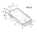
- FIG. 1Ais a front side perspective view of the case of FIG. 1 containing a mobile device
- FIG. 2is a top plan view of the case of FIG. 1 ;
- FIG. 3is a rear plan view of the case of FIG. 1 ;
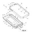
- FIG. 4is a front side perspective exploded view of a battery case according to the case of FIG. 1 ;
- FIG. 4Ais a right side plan magnified view of the interior of a bumper portion of the case of FIG. 1 ;
- FIG. 4Bis a top plan magnified view of a base portion of the case of FIG. 1 ;
- FIG. 4Cis a right side plan magnified view of a base portion of the case of FIG. 1 ;
- FIG. 5is a top schematic layout view illustrating the electrical components for the base portion of the case of FIG. 1 ;
- FIG. 6Ais a front side perspective view of a base portion of a case according to the case of FIG. 1 ;
- FIG. 6Bis a front side perspective view of a mobile device being secured on the base portion of a case according to the case of FIG. 1 ;
- FIG. 6Cis a front side perspective view of a mobile device being further secured in a case according to the case of FIG. 1 ;
- FIG. 6Dis a front plan view of a base portion of a mobile device in a case according to the case of FIG. 1 .
- FIG. 7is a front side perspective view of a charger according to another embodiment.
- FIG. 8is a rear plan view of the charger of FIG. 7 .
- FIG. 9is a front side perspective view of a kit according to yet another embodiment.
- FIG. 10is a left side plan view of the kit of FIG. 9 .
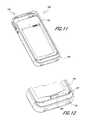
- FIG. 11is a front side perspective view of a system according to yet another embodiment.
- FIG. 12is a front side perspective magnified, cutaway view of a bottom portion of the system of FIG. 11 .
- An improved battery case for a mobile device and kitcomprising the improved battery case, rechargeable batteries, and a battery charger is disclosed herein.
- the embodiments disclosed hereinare described in the context of a battery case for a cell phone and associated kit for use with the cell phone because the embodiments disclosed herein have particular utility in this context.
- the embodiments and inventions hereincan also be applied to other types of electronic devices, including, but not limited to tablets, PDAs, e-readers, mp3 players (such as an iPod®), laptops, etc.
- an improved battery case for a mobile devicecan comprise a case 10 .
- the case 10generally comprises a base portion 20 and a side protector or bumper portion 12 .
- the case 10can be generally shaped to contain and protect a mobile device (e.g. an iPhone®).
- a mobile devicee.g. an iPhone®
- the mobile deviceFIGS. 6C and 6D
- the mobile devicedesirably fits snugly, although the user desirably still has access to the buttons and/or touch screen of the mobile device either directly through apertures in the case 10 or indirectly through button features included on the bumper portion 12 or base portion 20 .
- the bumper portion 12 and the base portion 20are attached together permanently or semi-permanently to comprise a single integral unit.
- the bumper portion 12 and the base portion 20comprise a case 10 that comprises two pieces that are releaseably attached together to contain a mobile device, as illustrated in the embodiment of FIG. 4 .
- the bumper portion 12can comprise a single piece, forming a perimeter of the case 10 .
- the bumper portion 12may comprise a first side or end 81 and a second side or end 82 opposite the first end 81 .
- the bumper portion 12may also have a third side 83 opposite a fourth side 84 .
- the bumpermay also have an inner surface 85 and an outer surface 86 .
- the bumper portion 12may also have a front edge 87 .
- the front edge 87is flush or substantially flush with the screen or display of a mobile device when the mobile device is within the case.
- the front edge 87extends over or overhangs at least a portion of the mobile device screen when a mobile device is inserted in case 10 .
- the bumpercomprises a single side protector which is configured to protect each of the four sides of a mobile device received within the case 10 .
- the casecould have one or more separate side protector corresponding to each individual side of the mobile device, or have one or more separate side protectors which wrap around the corner of the mobile device and therefore protect at least a portion of two or more sides of the mobile device.
- the continuous bumper portion 12may comprise two or more pieces that connect together to form a perimeter of the case 10 .
- the two or more piecesmay interlock together to protect the sides of a mobile device.
- the bumpermay comprise two or more pieces that may be integral with two or more pieces of the base portion of the case.
- the two or more pieces of the caseeach comprising a piece of a bumper portion and a piece of the base portion may connect to one another around a mobile device, via an appropriate mechanism such as a slide-and-lock mechanism.
- the bumper portionmay include feature apertures 14 corresponding to features on the mobile device, for example, the headphone inlet and the vibrate switch (illustrated). Other feature apertures may be incorporated into the bumper portion 12 to allow for access to the on/off button, speakers, volume controls, Bluetooth® switch, and other such features present on the mobile device.
- the bumper portion 12may also include button features 16 corresponding to other features on the mobile device such as volume controls and sleep or on/off switches (illustrated).
- the button features 16may also be formed into the bumper portion to correspond to other features of the mobile device.
- the button features 16may be raised and/or molded into the bumper portion 12 , as thus made of the same material of the bumper portion 12 . However, in some embodiments the button features 16 may be made of a different material than the bumper portion 12 , or they may comprise an additional material, such as rubber, coated on the button features 16 to improve tactility and use of the button features 16 .
- the bumper portion 12may be made of a plastic or polymeric material.
- the bumper portion 12is molded in a single piece, and is made of a suitable material such as polycarbonate, polypropylene, polyvinyl chloride, and the like.
- the bumper portion 12may be made by a suitable process such as injection molding.
- the bumper portion 12is made of a material that is suitably flexible to allow a mobile device to fit snugly within the bumper portion 12 and to allow the button features 16 to flex and contact the corresponding buttons on a mobile device without fracture.
- the materialmay be impact resistant enough to resist fracture when the case 10 containing a mobile device is dropped from a user's hand, a table, a desk and similar heights onto a variety of surfaces including concrete, asphalt, carpet, and the like.
- a heightmay include heights such as six feet, five feet, four feet, three feet, and the like.
- the bumper portion 12may be made of a plastic or polymer material that can be made in a variety of hues. By providing a bumper portion 12 that can be made in a variety of colors, a user can personalize the battery case 10 , without having to purchase a new base portion 20 , which may include components that are much more expensive and/or difficult to manufacture than bumper portion 12 .
- the bumper portion 12may be made of a plastic or polymeric material that is red, blue, orange, yellow, green, purple, pink, white, black, or a mixture of any of the above.
- the bumper portion 12in certain embodiments, may also be made of a variety of materials, thus allowing for further personalization of the case 10 .
- base portion 20forms the base of the case and is configured to support the mobile device and provide a base to which the bumper portion 12 can attach.
- the base portion 20may include a thin substantially rectangular body defining a back panel 29 adapted to form an outer surface of the case 10 and an inside panel 25 adapted to support and be positioned adjacent to a mobile device.
- the case and, desirably, the inside panel 25define a plane corresponding to the position of the back surface of the mobile device when it is positioned within the case 10 .
- the base portion 20may further include a nested portion 26 extending from the inside panel 25 opposite the back panel 29 .
- electrical contactsmay be present on the base portion of the case 20 .
- the electrical contactsmay be located near or on the bottom end of the base portion 20 . In other embodiments, the electrical contacts may be located elsewhere along the back panel 29 .
- the electrical contactsmay be configured to connect to a charging device.
- a data or charging devicemay comprise any device that may transfer power from a power source to the case 10 and/or charger 50 .
- the charging devicemay be a charging and/or data cable such as charging cable 1010 .
- the charging devicemay include a charging cradle 1090 in addition to or instead of a charging cable 1010 .
- a charging cradlemay include a base 1091 that may include a concave surface 1092 shaped to fit a case 10 .
- the concave surface 1092may also assist in holding a case alone or a case containing a mobile device upright.
- the charging cradlein some embodiments, may also be able to charge the charger 50 .
- the basemay be relatively planar, and the case may be laid flat upon the base.
- the charging cradle 1090may also include one or more leads 1093 that may transmit power to corresponding contacts on the case 10 or charger 50 when the contacts are touching the leads 1093 .
- the basemay also include a plug or port or means to provide power to the base.
- the base 1091may also include a plug or port or means to provide power to the base 1091 .
- the charging cradle 1090may include a port configured to plug into the case 10 to provide power to charge the case with or without a mobile device contained therein.
- a charging cradle 1090may be configured to charge the case with or without a rechargeable battery contained therein and with or without a mobile device.
- the charging cradle 1090may be able to charge any piece of the mobile device assembly inductively or conductively.
- the base portionmay further comprise a feature opening or window 21 , shaped to allow a view of a feature located on the rear of the mobile device, such as a camera lens (illustrated).
- a camera lens insert 21 Amay be inserted into the feature opening 21 .
- Such insertmay protect the case 10 from scratching the surface of a mobile device contained within the case.
- the base portionalso may define a battery aperture 22 , shaped to contain a rechargeable battery 40 . Electrical components (not illustrated) may also be contained within the base portion 20 .
- the nested portion 26may extend above the inside panel 25 so as to be flush or substantially flush with the outer edge of the bumper portion 12 .
- “substantially flush”may mean that the nested portion 26 extends above or below the bumper portion 12 , a distance of about 1 mm, 2 mm, 3 mm and the like.
- the nested portion 26may comprise a plug 28 and controls 27 .
- the inside panel 25 and bumper portion 12when the case is assembled, may form an inner portion containing the nested portion 26 , inside panel 25 of the base portion 20 , and the inner side of the bumper portion 12 .
- the inside panel 25may be attached to the back panel 29 by a suitable adhesive such as an epoxy or acrylic.
- Electrical componentswhich may be contained within the nested portion 26 , may comprise such components as wires, printed circuit boards, capacitors, resistors, and the like.
- the electrical componentsmay transfer the charge from the battery 40 , when placed in the battery aperture 22 to a mobile device connected to the plug 28 .
- the controls 27may also operate the electrical components.
- the electrical componentsmay also allow the battery 40 to be charged when placed in the battery aperture 22 in the case 10 when a charging cable 1010 is inserted into the inlet 31 and connected to a power source such as a computer or a power outlet.
- the charging and/or data cable 1010may have a male connector 1012 , at one end configured to be inserted into the case 10 , another male connector 1014 at the other end shaped to connect to a power source, and a wire 1013 joining the connectors 1012 , 1014 .
- the charging and/or data cable 1010may be capable of transferring power and/or data between a power source and/or computer and a case.
- the charging cable 1010may be any type of cable having any number of wires that can electronically connect the case 10 to a computer or power source.
- the cableis a USB cable (e.g., a USB 2.0 cable) where male connector 1012 is a USB mini-A plug and male connector 1014 is a USB type-B plug.
- the charging cable 1010may allow rechargeable battery 40 , an internal battery of a mobile device, or both to be charged by a computer and/or power source.
- the charging cable 1010when the charging cable 1010 connects the case 10 to a computer, the mobile device and the computer may be synchronized or synched.
- the cable 1010may be configured to transfer data from the mobile device contained within the case to a computer and/or from a computer to the mobile device contained within the case.
- the cable 1010may be able to charge an internal battery within the case, a rechargeable battery positioned within the case, or a mobile device placed inside of the case.
- the charging cablemay be able to charge a mobile device within a case, even though no rechargeable battery is present in the case.
- a headphone adapter 1080may be provided in the kit described above.
- the headphone adapter 1080may be generally configured to connect a headphone jack that is too large (e.g., has too large of a circumference) to fit through the opening in the case to properly connect within the headphone inlet of a mobile device, to a headphone jack inlet on a mobile device when the mobile device is within the case 10 .
- the headphone adapter 1080may have a female end 1081 connected to a male end 1082 by a connecting wire 1083 . In use, a user may plug a headphone jack (not pictured) into the female end 1081 , then the user may plug the male end 1082 into the mobile device.
- the usermay plug a distal end 1084 of the male end 1082 through the headphone aperture 1085 , and into a device within the case, as illustrated in FIG. 1A .
- the headphone adapter 1080can transmit sound from the mobile device through the adapter 1080 to the headphones.
- no external wiresuch as connecting wire 1083 , connects the male and female ends.
- the female end and male endare externally directly connected to one another.
- FIG. 5illustrates a schematic view of the case 10 illustrating the electrical components.
- PCBsprinted circuit boards
- the main PCB 1 1001is the main PCB, which may contain such items as a controller, firmware, an authentication chip, a battery charging circuit, and LEDs.
- PCB 2may contain a case connector, such as a 30 pin connector.
- PCB 3 1003may contain the USB connector.
- Main PCB 1 1001connects to PCB 2 1002 through a cable 1005 .
- Main PCB 1 1001also connects to PCB 3 1003 through a cable 1006 .
- Main PCB 1may also be electrically connected to the prongs 24 to transfer electrical charge to and from the rechargeable battery 40 .
- the battery aperture 22may be shaped to contain a rechargeable battery 40 and located on the inside panel 25 of the base portion 20 .
- the battery aperture 22may comprise a detent 23 shaped in a semi hemispherical fashion to allow a user to easily remove a battery 40 from the battery aperture 22 .
- the battery aperture 22may also comprise conductors, such as leads or prongs 24 to allow a battery 40 , when placed in the case, to transfer electrical charge to the electrical components within the base portion 22 (not illustrated).
- the prongs 24may also provide additional pressure to the battery 40 , when placed in the battery aperture 22 , to assist in keeping the battery 40 in place in the base portion 20 .
- the battery 40may be shaped generally rectangularly to fit in the battery aperture 22 .
- the battery 40may have a top end 42 , a bottom end 44 , a left side 46 , and a right side 48 .
- Electrical connectors 45may be disposed on the bottom end 44 and be located on the bottom end to correspond with the prongs 24 in the battery aperture 22 . This may allow for an electrical charge to transmit between the battery 40 and the electrical components.
- the battery 40may have a thickness t.
- the thickness tmay be roughly the same as the height of the battery aperture. Hence, when the battery 40 is in place in the battery aperture 22 , a mobile device, when placed in the case 10 lies flat. In some embodiments, the thickness t may be slightly less than the height of the battery aperture, hence still allowing the mobile device when placed in the case to lie flat.
- the thickness t of the battery 40is in the range of between 2 mm (or about 2 mm) and 12 mm (or about 12 mm) thick. According to other embodiments, the thickness t is in the range of between 3 mm (or about 3 mm) and 10 mm (or about 10 mm), between 3 mm (or about 3 mm) and 7 mm (or about 7 mm), between 6 mm (or about 6 mm) and 9 mm (or about 9 mm), or between 7 mm (or about 7 mm) and 8 mm (or about 8 mm).
- the thickness t of the battery 40is less than 13 mm (or about 13 mm), less than 10 mm (or about 10 mm), less than 8 mm (or about 8 mm), less than 7 mm (or about 7 mm), less than 6 mm (or about 6 mm), or less than 5 mm (or about 5 mm).
- the battery 40may comprise any suitable (preferably rechargeable) battery.
- the batterymay be able to hold 3.7 V or 1700 mAh of charge, 1600 mAh of charge, and the like.
- Such batteriesmay include a lithium ion battery.
- the batterymay be a nickel cadmium, nickel metal hydride, lithium-ion polymer, lithium polymer, lead acid, or any other type of rechargeable battery.
- the batterymay be disposable.
- the batterymay be advantageously shaped to fit within the battery aperture 22 .
- the batterymay comprise one or more batteries, for example two batteries, three batteries, ten batteries, or however many a user may possess.
- the battery aperture 22located roughly in the center of the inside panel 25 of the base portion 20
- the battery aperturemay be located on any portion of the inside panel 25 of the base portion 22 , e.g. near the top, bottom, left hand side, right hand side, and the like.
- the battery aperturemay be located on the back panel 29 of the base portion 20 .
- the battery aperturemay be covered by a door that may be opened by a user by pressure, or by pressing a button located on the base portion 20 .
- the plug 28may extend from the nested portion 26 and be adapted to be inserted into the port jack of a mobile device.
- the plug 28may be able to communicate electronically with a mobile device and deliver charge to a mobile device from the case 10 containing a battery 40 containing at least a partial charge.
- the plug 28may also be configured to send data to and receive data from a mobile device.
- the controls 27 of the nested portion 26may allow a user to turn the battery case on or off and/or check the charge level of the rechargeable battery 40 when inside of the case 10 .
- the charge levelmay be indicated by lights such as LED lights 2030 located inside and visible on the surface of the nested portion 26 .
- the controls 27may also comprise a light that illuminates when the case is on and is providing charge to a mobile device or if the charge level is being tested. The light corresponding to the controls 27 may turn off when the case 10 is not being used to provide charge to a mobile device such as when the user presses the control to turn the power off or when the case runs out of battery energy or if there is no battery 40 within the battery aperture 22 .
- the nested portion 26may also comprise an inlet 31 .
- the inlet 31may correspond to or receive a charging cable 1010 that may be used to charge the battery 40 when contained in the battery aperture 22 without removing the battery 40 from the case 10 .
- the charging cablemay be configured to plug into a power source, for example, a computer or laptop device, a car outlet, a power outlet and the like.
- the nested portionmay comprise a speaker aperture 32 that may correspond to the speaker of a mobile device.
- the speaker aperturemay allow access to the speaker of the mobile device so that the user may listen to music or audio from a mobile device without the case 10 obstructing the sound.
- the base portion 20may comprise more than one speaker aperture in different locations, corresponding to the speaker location on the mobile device.
- the back panel 29is made of a lighter plastic or polymeric material than the inside panel 25 that reduces the total weight of the case 10 .
- the materialmay be impact resistant enough to resist fracture when the case 10 containing a mobile device is dropped from a user's hand, a table, a desk and similar heights onto a variety of surfaces including concrete, asphalt, carpet, and the like. Such a height may include heights such as six feet, five feet, four feet, three feet, and the like.
- the materialmay also exhibit beneficial properties such as scratch resistance, modulus, and the like.
- the inside panel 25may extend above the back panel 29 , forming a peripheral flange 1050 .
- the peripheral flange 1050may include one or more tabs 33 and recesses 34 , corresponding to tabs 18 and recesses 19 on the bumper portion 12 .
- the base portion 20 and the bumper portion 12 of the case 10then may be attached to one another by aligning the bumper portion 12 with the base portion 20 and applying pressure to force the corresponding tabs and recesses on the bumper portion 12 and base portion 20 to interlock with one another and snap into place.
- a usermay flex the bumper portion 12 so that one or more of the corresponding recesses and tabs detach from one another, allowing the bumper portion 12 to release from the base portion 20 .
- the bumper portion 12 or the base portion 20may comprise tabs or recesses.
- the bumper portionmay comprise a single, uniform tab extending inwardly around the perimeter of the inner surface 85
- the base portioncomprises a uniform recess extending inwardly around the perimeter of the peripheral flange that receives the uniform tab of the bumper portion.
- the bumper portion and the base portionmay be designed with a system of tabs and inlets or indents that securely fit the two pieces together in place to prevent separation of the bumper portion from the base portion when the assembled case is dropped from a user's hand, a table, a desk and similar heights onto a variety of surfaces including concrete, asphalt, carpet, and the like.
- a heightmay include heights such as six feet, five feet, four feet, three feet, and the like. According to some embodiments, this configuration allows the bumper portion and the base portion to stay attached to one another both when a mobile device is contained within the assembled case and when a mobile device is not contained within the assembled case.
- a usermay insert a rechargeable battery and mobile device into the case 10 to provide extra electrical charge to the mobile device to charge an internal battery in a mobile device.
- a rechargeable battery 40holding at least a partial charge, is inserted into the battery aperture 22 in the base portion 20 .
- the usermay attach a mobile device 1060 to the base portion 20 by connecting a mobile device 1060 to the plug 28 .
- FIG. 6Afirst a rechargeable battery 40 , holding at least a partial charge, is inserted into the battery aperture 22 in the base portion 20 .
- the usermay attach a mobile device 1060 to the base portion 20 by connecting a mobile device 1060 to the plug 28 .
- the usermay attach the bumper portion 12 to the base portion 20 by aligning the bumper portion 12 with the base portion 20 and applying pressure to force the corresponding tabs and recesses on the bumper portion 12 and base portion 20 to interlock with one another and snap into place, thus securing a mobile device 1060 within the case 10 .
- the mobile devicemay display an indicator 1062 on its screen 1061 to confirm that an electrical charge is being provided to the mobile device 1060 through the case.
- the bumper portion 12may extend around the sides of a mobile device.
- the inner side of the bumper portion 12may contact a mobile device.
- the nested portion 26may contact a bottom edge of a mobile device.
- the inside panel 25 of the base portion 20may contact or partially contact a back side of a mobile device.
- a portion of the bumper portion 12may extend partially over a front side of a mobile device to help secure a mobile device in the case 10 .
- the front of a mobile device 1060may comprise the display of a mobile device, a keyboard, a rollerball, a control pad, a touch screen (for example, 1061 in FIG. 6D ), and the like.
- the bumper portiondesirably surrounds each of the sides of the four corners of the mobile device. Desirably, the bumper portion surrounds each of the ends and sides of the mobile device. Desirably, the bumper portion substantially covers each of the sides of the four corners of the mobile device. Desirably, the bumper portion substantially covers each of the ends and sides of the mobile device.
- FIG. 7illustrates a charger 50 according to an embodiment.
- the charger 50may have a top end 91 , a bottom end 92 , a left side 93 , and a right side 94 .
- the charger 50may also have a front side defining a front face 95 of the charger and a rear side defining a rear face 96 of the case.
- the charger 50also comprises a side edge 1070 that defines the side perimeter and thickness of the charger, and connects the front face 95 and the rear face 96 .
- the charger 50is generally provided to charge a rechargeable battery 40 , as described previously.
- the chargermay be shaped in a generally rectangular fashion. However, in other, non-illustrated embodiments, the charger may be generally circular, triangular, or any other suitable geometric shape.
- the charger 50may define a battery aperture 52 , shaped to contain a rechargeable battery 40 .
- the battery aperture 52may comprise a detent 54 shaped in a semi hemispherical fashion to allow a user to easily remove a battery 40 from the battery aperture 52 .
- the charger 50may also comprise an inlet 55 .
- the inlet 55may correspond to a charging device (such as cable 1010 in FIG. 1 ) that may be used to charge the battery 40 when the battery 40 is placed in the battery aperture 52 .
- LED light 51located on the front face 95 of the case, may become illuminated when the charger is connected to a power source by the charging cable.
- the charging cablemay be configured to plug into a power source, for example, a computer or laptop device, a car outlet, a power outlet and the like.
- the charging cablemay be of the same type disclosed above.
- the charger 50comprises a mount instead of an aperture shaped like the battery 40 .
- the mountmay comprise metal prongs to transfer power from a charger to the battery attached to the mount.
- a mountmay support the battery in the charger, but without surrounding the battery on all four sides as the embodiment illustrated in FIG. 7 .
- the charger 50may also comprise conductors, such as leads or prongs 58 .
- the prongs 58may extend from an end wall defining the battery aperture and allow an electrical charge to be transferred to a battery 40 when placed in the charger 50 when a charging cable is connected to the inlet 55 and a power source.
- the prongs 58may also provide additional pressure to the battery 40 , when placed in the battery aperture 52 , to assist in keeping the battery 40 in place in the charger 50 .
- the prongs 58may also transfer electrical charge from the battery 40 in the charger when the charger 50 is unplugged from a power source.
- FIG. 8illustrates another view of an embodiment of the charger 50 .
- the back side of the charger 50may comprise a layer 56 of material.
- the layer 56may comprise a polymeric material such as rubber.
- the layer 56may be tacky.
- the layer 56may exhibit a coefficient of fraction in the range of 0.75-4.5.
- the layer 56may prevent the charger 50 from sliding when subjected to a shearing or linear force when on a hard, flat or relatively surface such as a table, desk, car dashboard, airplane or train tray table, and the like.
- the layer 56may prevent the charger from sliding or otherwise coming displaced when placed inside of the case 10 .
- the layer 56may prevent the charger from sliding when placed on top of the inside panel 25 of the base portion 20 .
- the chargermay comprise an additional port that may be used to transfer power from a battery in the charger, when the battery contains a charge, to another power receiving entity.
- the portmay comprise an USB port.
- the chargermay also transfer power from a battery within the charger containing a charge to charge a laptop, tablet, PDA, e-reader, mp3 player (such as an iPod®), or any other suitable electronic device.
- the chargermay also comprise an aperture shaped to form a negative impression of a data port.
- a charger 50may be able to discharge power from a rechargeable battery contained within, to the case 10 when a port on the charger is inserted into the inlet 31 .
- the chargermay have an insert configured to receive either a micro-usb end or a USB end or any end of a charging cable.
- one charging cablemay be used to connect the charger to a power source, and a different charging cable inserted in the insert may be connected to the inlet of a case.
- This configurationmay allow for a rechargeable battery contained within the charger, the case, and/or a mobile device contained within the case, and/or a rechargeable battery contained within the case to all be charged at the same time.
- the power sourcecharges the charger, which in turn charges the case, which in turn charges a rechargeable battery contained within the case and/or a mobile device contained within the case.
- FIG. 9illustrates an embodiment of a kit 70 comprising a case 110 , a charger 150 , and at least one rechargeable battery 140 .
- the case 110 , charger 150 , and/or at least one rechargeable battery 140encompass the features discussed in the embodiments of cases, chargers, and rechargeable batteries discussed above.
- the charger 150fits within the perimeter of the case 110 .
- the charger 150may contact the inner surface 125 of the case 110 .
- the charger 150is contained within the case by the bumper portion 112 .
- the bumper portionmay define at least one sidewall which extends transverse to the plane which corresponds to the rear surface of the mobile device when the mobile device is received by the case.
- the inside panel 25 and the planeare positioned horizontally and, accordingly, the sidewall extends transversely or, preferably vertically.
- the charger 150is flush or substantially flush with the top edge of the bumper portion 112 .
- the bumper portion 112has a depth d. The depth of the charger 150 may be equal to or less than d.
- the charger 150when the charger 150 is positioned inside of the case 110 , the charger 150 does not extend above at least one, and preferably above any vertically extending side of the case. This may mean that the charger 150 is flush with the bumper portion 112 , or that, when placed against the inner surface 125 of the case 120 , the charger 150 does not extend as high vertically as the bumper portion.
- a battery 140may also be stored in the battery aperture 152 of the charger 150 when it is placed in the case 110 .
- a rechargeable battery 140may be placed in a battery aperture of the case 110 (not illustrated) when the charger 150 is placed in the case.
- a rechargeable batterymay be placed in the battery aperture 152 of the charger 150 and a different rechargeable battery may be placed in the battery aperture of the case 110 .
- a kit according to an embodimentmay be able to store up to at least two rechargeable batteries and the charger in the space of the case 110 itself.
- the charger's compact design and ability to fit within the caseallows for the kit described in aforementioned embodiments to travel easily.
- the compact kitmay be able to fit into backpacks, luggage, purses, pockets, and the like for easy travel. Also, the ability for the pieces of the kit to fit within one another lessens the likelihood that the pieces of the kit will become separated from one another in a large bag or purse.
- the chargerhas a polymeric coating on the back of the charger that prevents the charger from slipping when placed in the case. This coating, in some embodiments, may also help adhere the charger to the case when a user is traveling, so that the components of the kit are more likely to stay together.
- the kitalso has the ability to provide a continuous stream of power to a mobile device over an extended period of time.
- a usermay charge a rechargeable battery using the charger while a mobile device is inserted into the case where an already-charged rechargeable battery has already been inserted into the case.
- the usermay use the controls to transfer power to the mobile device when needed (e.g., when the mobile device runs out of its own internal battery).
- a usermay remove the mobile device, remove the drained battery, replace the drained battery in the battery aperture of the case with the rechargeable battery containing at least a partial charge, replace the mobile device in the case, then use the controls when necessary to provide additional charge to the mobile device.
- the drained batterymay be inserted into the charger, which may be then connected to a power source to restore charge to the rechargeable battery.
- a power sourceto restore charge to the rechargeable battery.
- several pre-charged rechargeable batteriesmay be carried by the user, so that a recharging step is unnecessary.
- a userBy cycling draining and charging rechargeable batteries within the case and charger, respectively, a user can keep their mobile device on and/or functioning for extending periods of time without having to plug either the phone or the case into a power source. This is beneficial for circumstances where a user may have limited or no access to a power supply, e.g. on a long flight or train ride, at an airport or train station, on a long car ride, when travelling in the wilderness, and the like.
- a system 200may comprise a case 210 and a charger 250 configured to attach to the interior of the case 210 .
- the systemmay also include one or more rechargeable batteries 240 .
- the case 210 , charger 250 , and/or at least one rechargeable battery 240encompass the features discussed in the embodiments of cases, chargers, and rechargeable batteries discussed in embodiments above.
- the embodiment of FIG. 11shows the charger 250 attached to the case 210 .
- the charger 250may have a recess defining a negative relief image of a protrusion in the case 210 .
- the recessmay be shaped to receive a data port protrusion.
- the recessmay be shaped to receive a protrusion that has been pre-formed into the base portion 210 or the bumper portion 212 of the case.
- FIG. 12illustrates a magnified view of the bottom portion of the embodiment of FIG. 11 , with a cutaway view of the port 228 inside of the charger recess 257 .
- the charger 250is securely connected to the nested portion 226 of the base portion 220 of the case 210 via the port 228 .
- the charger 250desirably should not separate from the case 210 due to common forces that an object may experience when in a purse, backpack, luggage and the like. This can ensure that the pieces of the system 200 do not come separated from one another in travel and are thus easy for a user to find as well as compact.
- the chargerfurther comprises a mechanism such as a latch in the recess to further guarantee that the charger will not come separated from the case when they are connected to one another during travel.
- the chargercomprises a button connected to the latch that the user can press to release the latch and the charger from the case after the charger has been connected to the case.
Landscapes
- Engineering & Computer Science (AREA)
- Theoretical Computer Science (AREA)
- Human Computer Interaction (AREA)
- Power Engineering (AREA)
- Computer Hardware Design (AREA)
- Physics & Mathematics (AREA)
- General Engineering & Computer Science (AREA)
- General Physics & Mathematics (AREA)
- Signal Processing (AREA)
- Computer Networks & Wireless Communication (AREA)
- Charge And Discharge Circuits For Batteries Or The Like (AREA)
Abstract
Description
Claims (15)
Priority Applications (5)
| Application Number | Priority Date | Filing Date | Title |
|---|---|---|---|
| US13/489,325US8390255B1 (en) | 2012-05-25 | 2012-06-05 | Battery case for mobile device |
| US13/783,129US9071060B2 (en) | 2012-05-25 | 2013-03-01 | Battery case for mobile device |
| US14/586,760US9997751B2 (en) | 2012-05-25 | 2014-12-30 | Battery case for mobile device |
| US14/749,228US9461493B2 (en) | 2012-05-25 | 2015-06-24 | Battery case for mobile device |
| US15/284,503US20170025873A1 (en) | 2012-05-25 | 2016-10-03 | Battery case for mobile device |
Applications Claiming Priority (2)
| Application Number | Priority Date | Filing Date | Title |
|---|---|---|---|
| US201261651981P | 2012-05-25 | 2012-05-25 | |
| US13/489,325US8390255B1 (en) | 2012-05-25 | 2012-06-05 | Battery case for mobile device |
Related Child Applications (1)
| Application Number | Title | Priority Date | Filing Date |
|---|---|---|---|
| US13/783,129ContinuationUS9071060B2 (en) | 2012-05-25 | 2013-03-01 | Battery case for mobile device |
Publications (1)
| Publication Number | Publication Date |
|---|---|
| US8390255B1true US8390255B1 (en) | 2013-03-05 |
Family
ID=47748990
Family Applications (4)
| Application Number | Title | Priority Date | Filing Date |
|---|---|---|---|
| US13/489,325Expired - Fee RelatedUS8390255B1 (en) | 2012-05-25 | 2012-06-05 | Battery case for mobile device |
| US13/783,129Expired - Fee RelatedUS9071060B2 (en) | 2012-05-25 | 2013-03-01 | Battery case for mobile device |
| US14/749,228Expired - Fee RelatedUS9461493B2 (en) | 2012-05-25 | 2015-06-24 | Battery case for mobile device |
| US15/284,503AbandonedUS20170025873A1 (en) | 2012-05-25 | 2016-10-03 | Battery case for mobile device |
Family Applications After (3)
| Application Number | Title | Priority Date | Filing Date |
|---|---|---|---|
| US13/783,129Expired - Fee RelatedUS9071060B2 (en) | 2012-05-25 | 2013-03-01 | Battery case for mobile device |
| US14/749,228Expired - Fee RelatedUS9461493B2 (en) | 2012-05-25 | 2015-06-24 | Battery case for mobile device |
| US15/284,503AbandonedUS20170025873A1 (en) | 2012-05-25 | 2016-10-03 | Battery case for mobile device |
Country Status (1)
| Country | Link |
|---|---|
| US (4) | US8390255B1 (en) |
Cited By (101)
| Publication number | Priority date | Publication date | Assignee | Title |
|---|---|---|---|---|
| US20120282977A1 (en)* | 2011-05-05 | 2012-11-08 | Robert Haleluk | Case for mobile communication device with flash and camera controls |
| US20130191575A1 (en)* | 2011-12-21 | 2013-07-25 | Hendricks Investment Holdings, Llc | Methods and systems for providing alternative storage resources |
| US20130193756A1 (en)* | 2012-02-01 | 2013-08-01 | Canon Kabushiki Kaisha | Power supply device, electronic device, control method, and recording medium |
| USD688234S1 (en)* | 2012-12-20 | 2013-08-20 | Premier Accessory Group LLC | Mobile device case |
| USD699717S1 (en)* | 2012-09-11 | 2014-02-18 | Apple Inc. | Housing for an electronic device |
| US20140092564A1 (en)* | 2012-09-28 | 2014-04-03 | Htc Corporation | Electronic apparatus and method for assembling the same |
| US20140192493A1 (en)* | 2013-01-09 | 2014-07-10 | Freeway Design End Development Ltd. | Supplementary elements for a handheld device and methods of manufacturing thereof |
| US20140239916A1 (en)* | 2013-02-25 | 2014-08-28 | Mophie, Inc. | Protective case with switch cover |
| US20140302896A1 (en)* | 2013-04-04 | 2014-10-09 | Ye Xu | Portable Charging System for a Smartphone |
| US20140321048A1 (en)* | 2013-04-30 | 2014-10-30 | Victor Kupferstein | Mobile device case and peripheral system |
| US8955678B2 (en) | 2013-03-14 | 2015-02-17 | Pelican Products, Inc. | Protective cases for mobile electronic communication devices |
| USD729299S1 (en) | 2012-11-09 | 2015-05-12 | I.Am.Symbolic, Llc | Mobile device camera enclosure with keyboard |
| US20150133204A1 (en)* | 2013-12-03 | 2015-05-14 | Vladimir Ivanovski | Modular mobile device case |
| USD732598S1 (en) | 2012-11-09 | 2015-06-23 | I.Am.Symbolic, Llc | Mobile device camera enclosure |
| US9071060B2 (en) | 2012-05-25 | 2015-06-30 | Incipio Technologies, Inc. | Battery case for mobile device |
| US20150205331A1 (en)* | 2014-01-21 | 2015-07-23 | Dell Products L.P. | Convertible Information Handling System Input Device Surface and Support |
| USD739452S1 (en) | 2012-11-09 | 2015-09-22 | I.Am.Symbolic, Llc | Mobile device camera accessory |
| CN105144590A (en)* | 2013-03-15 | 2015-12-09 | 摩飞公司 | Protective case for mobile device |
| US20150364875A1 (en)* | 2014-06-13 | 2015-12-17 | Ezra J. Ginsberg | Mobile device case with retractable cable |
| US20150364943A1 (en)* | 2014-06-16 | 2015-12-17 | Wistron Corporation | Wirelessly charging a mobile device and utilizing the mobile device as a power source |
| US9282668B2 (en) | 2012-09-28 | 2016-03-08 | Htc Corporation | Electronic apparatus and method for assembling the same |
| US20160087469A1 (en)* | 2014-09-23 | 2016-03-24 | Deborah A. Armstrong | Portable Electronic Storage and Charging Apparatus |
| US9319501B2 (en) | 2010-05-19 | 2016-04-19 | Mophie, Inc. | External processing accessory for mobile device |
| US9332329B2 (en) | 2012-09-28 | 2016-05-03 | Htc Corporation | Electronic apparatus |
| USD756910S1 (en)* | 2014-12-19 | 2016-05-24 | Sumeet Kumar Gupta | Combination battery and case for electronic equipment |
| USD756911S1 (en)* | 2014-12-19 | 2016-05-24 | Sumeet Kumar Gupta | Combination battery and case for electronic equipment |
| USD756909S1 (en)* | 2014-12-19 | 2016-05-24 | Sumeet Kumar Gupta | Combination battery and case for electronic equipment |
| US9356267B1 (en) | 2014-12-17 | 2016-05-31 | Mophie, Inc. | Protective battery case to partially enclose a mobile electronic device |
| US9406913B2 (en) | 2008-01-18 | 2016-08-02 | Mophie, Inc. | Battery case for mobile devices |
| US9402452B2 (en) | 2008-11-17 | 2016-08-02 | Mophie, Inc. | Method of making a smartphone case with a battery |
| USD763187S1 (en)* | 2014-06-20 | 2016-08-09 | Appcessory Pte Ltd | Smartphone battery |
| US20160269512A1 (en)* | 2013-10-17 | 2016-09-15 | Zte Corporation | Terminal cover body and terminal |
| USD766819S1 (en) | 2015-04-06 | 2016-09-20 | Mophie, Inc. | Protective battery case |
| EP3072412A1 (en)* | 2015-03-25 | 2016-09-28 | Tech 21 Licensing Limited | A case for a mobile electronic device |
| US9464796B2 (en) | 2012-02-03 | 2016-10-11 | Lumee, Llc | Illumination device |
| US9495375B2 (en) | 2013-11-27 | 2016-11-15 | Mophie, Inc. | Battery pack with supplemental memory |
| US9509358B1 (en) | 2015-09-04 | 2016-11-29 | Alpha Audiotronics, Inc. | Behavior adaptive battery control system for mobile device case |
| US9520912B1 (en)* | 2015-07-16 | 2016-12-13 | Cretronix, Inc. | Shock absorbing phone case with hidden compartment |
| WO2016200561A1 (en)* | 2015-06-10 | 2016-12-15 | Lumee, Llc | Illumination device |
| US9577695B2 (en) | 2008-01-18 | 2017-02-21 | Mophie, Inc. | Wireless communication accessory for a mobile device |
| US9593842B2 (en) | 2012-02-03 | 2017-03-14 | Lumee Llc | Illumination device |
| US9635736B2 (en) | 2015-04-23 | 2017-04-25 | Boogli, Inc. | System and method for providing device accessory illumination based on device-related information |
| US9635157B2 (en) | 2014-01-07 | 2017-04-25 | Boogli, Inc. | System and method for augmenting a second item with a presentation of features at a first item |
| US9647474B2 (en) | 2014-01-06 | 2017-05-09 | Incipio, Llc | Protective case for mobile device with auxiliary battery and power control |
| US9654606B1 (en) | 2015-05-05 | 2017-05-16 | Boomerang Innovations, Inc. | Multifunctional mobile device case |
| US20170194997A1 (en)* | 2016-01-04 | 2017-07-06 | Incipio, Llc | Molded mobile device case with storage compartment having hinged access |
| US20170227987A1 (en)* | 2014-02-24 | 2017-08-10 | National Products, Inc. | Docking sleeve with electrical adapter |
| USD797093S1 (en) | 2014-12-03 | 2017-09-12 | Mophie, Inc. | Case for a mobile electronic device |
| USD797091S1 (en) | 2014-11-25 | 2017-09-12 | Mophie, Inc. | Case for a mobile electronic device |
| USD797092S1 (en) | 2014-11-25 | 2017-09-12 | Mophie, Inc. | Case for a mobile electronic device |
| US9807483B1 (en) | 2016-12-07 | 2017-10-31 | BassCase LLC | Mobile device case with foldable speaker system |
| US9831905B1 (en) | 2016-10-12 | 2017-11-28 | Pelican Products, Inc. | Control feature of a protective case for engaging a switch of an electronic device |
| US20170371378A1 (en)* | 2014-10-06 | 2017-12-28 | Fasetto, Llc | Portable storage device with modular power and housing system |
| US9906851B2 (en) | 2016-05-20 | 2018-02-27 | Evolved Audio LLC | Wireless earbud charging and communication systems and methods |
| CN107810461A (en)* | 2015-06-29 | 2018-03-16 | 国家产品股份有限公司 | Head containing electrical interconnecting to female connector |
| US20180131227A1 (en)* | 2016-11-08 | 2018-05-10 | Lenovo (Singapore) Pte. Ltd. | Supplemental batteries for electronic devices |
| US9997933B2 (en) | 2014-09-03 | 2018-06-12 | Mophie, Inc. | Systems and methods for battery charging and management |
| US9997751B2 (en) | 2012-05-25 | 2018-06-12 | Incipio, Llc | Battery case for mobile device |
| TWI629582B (en)* | 2015-06-29 | 2018-07-11 | 全國產品公司 | Butt sleeve with electrical adapter |
| US10050658B2 (en)* | 2014-02-24 | 2018-08-14 | National Products, Inc. | Docking sleeve with electrical adapter |
| US10070022B2 (en) | 2016-01-20 | 2018-09-04 | Boogli, Inc. | Elongated flexible child monitor |
| US10075502B2 (en) | 2015-03-11 | 2018-09-11 | Fasetto, Inc. | Systems and methods for web API communication |
| US10084688B2 (en) | 2014-01-27 | 2018-09-25 | Fasetto, Inc. | Systems and methods for peer-to-peer communication |
| US10095873B2 (en) | 2013-09-30 | 2018-10-09 | Fasetto, Inc. | Paperless application |
| US10103557B1 (en)* | 2014-12-03 | 2018-10-16 | Tyler Rhys Waylett | Rechargeable battery system |
| US10123153B2 (en) | 2014-10-06 | 2018-11-06 | Fasetto, Inc. | Systems and methods for portable storage devices |
| USD836646S1 (en)* | 2016-07-14 | 2018-12-25 | Clarion Technologies, Inc. | Device mount for scanner |
| USD855601S1 (en) | 2015-09-14 | 2019-08-06 | Mophie Inc. | Case for a mobile electronic device |
| US10404088B2 (en)* | 2015-06-06 | 2019-09-03 | Apple Inc. | Power distribution using bidirectional power connector |
| USD860179S1 (en) | 2016-03-03 | 2019-09-17 | Mophie Inc. | Case for a mobile electronic device |
| USD861653S1 (en) | 2015-05-27 | 2019-10-01 | Mophie Inc. | Protective battery case for mobile communications device |
| USD861654S1 (en) | 2016-03-03 | 2019-10-01 | Mophie Inc. | Case for a mobile electronic device |
| US10495946B2 (en) | 2012-02-03 | 2019-12-03 | Case-Mate, Inc. | Illumination device |
| US10516431B2 (en) | 2017-11-21 | 2019-12-24 | Mophie Inc. | Mobile device case for receiving wireless signals |
| US10533714B2 (en) | 2014-05-10 | 2020-01-14 | VisionQuest Imaging, Inc. | External lighting cases for mobile digital camera devices |
| US10712898B2 (en) | 2013-03-05 | 2020-07-14 | Fasetto, Inc. | System and method for cubic graphical user interfaces |
| WO2020172347A1 (en)* | 2019-02-20 | 2020-08-27 | Acouva, Inc. | Multi function charger case |
| US10763630B2 (en) | 2017-10-19 | 2020-09-01 | Fasetto, Inc. | Portable electronic device connection systems |
| US10812643B1 (en) | 2020-05-04 | 2020-10-20 | National Products, Inc. | Cases for mobile devices incorporating a light within the case and methods of making and using |
| US10892625B1 (en) | 2017-02-17 | 2021-01-12 | Apple Inc. | Cases and folios for carrying and charging accessories |
| US10904717B2 (en) | 2014-07-10 | 2021-01-26 | Fasetto, Inc. | Systems and methods for message editing |
| US10929071B2 (en) | 2015-12-03 | 2021-02-23 | Fasetto, Inc. | Systems and methods for memory card emulation |
| US10956589B2 (en) | 2016-11-23 | 2021-03-23 | Fasetto, Inc. | Systems and methods for streaming media |
| US10979466B2 (en) | 2018-04-17 | 2021-04-13 | Fasetto, Inc. | Device presentation with real-time feedback |
| US11029731B1 (en) | 2020-04-20 | 2021-06-08 | National Products, Inc. | Cradles and cases for mobile devices incorporating guide elements or modular components and methods of making and using |
| US11076032B1 (en) | 2020-05-26 | 2021-07-27 | National Products, Inc. | Cradles for mobile devices with a plunger lock and methods of making and using |
| USD940647S1 (en) | 2019-01-07 | 2022-01-11 | Mophie Inc. | Battery pack |
| US11233411B2 (en)* | 2016-09-26 | 2022-01-25 | Snap Inc. | Multifunctional case for electronics-enabled eyewear |
| US11277506B2 (en) | 2020-05-26 | 2022-03-15 | National Products, Inc. | Cradles for mobile devices with one or more biasing tabs and methods of making and using |
| US11289864B2 (en) | 2020-04-20 | 2022-03-29 | National Products, Inc. | Cases for mobile devices with a flexible covering and rigid frame or with two different connector arrangements and methods of making and using |
| USD950538S1 (en)* | 2016-03-03 | 2022-05-03 | Mophie Inc. | Case for a mobile electronic device |
| US11489350B2 (en) | 2019-12-23 | 2022-11-01 | National Products, Inc. | Cradle for mobile devices with resilient guides and methods of making and using |
| US11652326B2 (en) | 2021-04-30 | 2023-05-16 | National Products, Inc. | Dock with flexible locator pins and methods of making and using |
| US11708051B2 (en) | 2017-02-03 | 2023-07-25 | Fasetto, Inc. | Systems and methods for data storage in keyed devices |
| US11728846B1 (en) | 2022-10-13 | 2023-08-15 | National Products, Inc. | Remote repeater device for mobile device dock and methods of making and using |
| US11985244B2 (en) | 2017-12-01 | 2024-05-14 | Fasetto, Inc. | Systems and methods for improved data encryption |
| US12126199B2 (en) | 2021-08-09 | 2024-10-22 | National Products, Inc. | Cradles for a mobile device including a cavity for a wireless device and methods of making and using |
| US12158776B2 (en) | 2022-04-25 | 2024-12-03 | National Products, Inc. | Docks for mobile devices with simultaneous data transfer and charging and systems and methods using the docks |
| US12298809B2 (en) | 2023-07-05 | 2025-05-13 | National Products, Inc. | Heating module for electronic device dock and methods of making and using |
| US20250224768A1 (en)* | 2024-01-04 | 2025-07-10 | National Products, Inc. | Case with removable endpiece for portable electronic device and methods of using |
| US12362527B2 (en) | 2020-06-10 | 2025-07-15 | National Products, Inc. | Cases for mobile devices incorporating a cord extending from the case and methods of making and using |
Families Citing this family (26)
| Publication number | Priority date | Publication date | Assignee | Title |
|---|---|---|---|---|
| US9092300B2 (en)* | 2013-04-18 | 2015-07-28 | Ottr Products, Llc | Peripheral device and method for updating firmware thereof |
| GB2516295A (en)* | 2013-07-18 | 2015-01-21 | Marcus Lewis | Keypad |
| CN203813456U (en)* | 2013-12-11 | 2014-09-03 | 深圳市万拓电子技术有限公司 | Cell phone standby power supply |
| US11356543B2 (en)* | 2013-12-20 | 2022-06-07 | Cognex Corporation | Image module including mounting and decoder for mobile devices |
| US10229303B2 (en) | 2013-12-20 | 2019-03-12 | Cognex Corporation | Image module including mounting and decoder for mobile devices |
| KR102192148B1 (en)* | 2013-12-27 | 2020-12-16 | 삼성전자주식회사 | Protective cover and electronic device having it |
| EP3111291A1 (en)* | 2014-02-24 | 2017-01-04 | National Products, Inc. | Docking sleeve with electrical adapter |
| US9680977B2 (en)* | 2014-06-26 | 2017-06-13 | Anatoliy Babayev | Voice only phone and method of operation |
| US9634709B2 (en) | 2014-09-04 | 2017-04-25 | Apple Inc. | Removable electronic device case with supplemental antenna element |
| TWI519935B (en)* | 2014-11-24 | 2016-02-01 | 緯創資通股份有限公司 | Electronic device having thermoelectric conversion module |
| WO2016100331A1 (en)* | 2014-12-17 | 2016-06-23 | Mophie, Inc. | Protective battery case |
| KR102296909B1 (en)* | 2015-01-09 | 2021-09-01 | 삼성전자주식회사 | Portable device comprising auxiliary battery and auxiliary battery charging method thereof |
| USD767485S1 (en)* | 2015-04-07 | 2016-09-27 | Mophie, Inc. | Battery case |
| US9654164B2 (en)* | 2015-04-14 | 2017-05-16 | Apple Inc. | Removable electronic device case with supplemental wireless circuitry |
| US9991926B2 (en)* | 2015-09-04 | 2018-06-05 | Asterisk, Inc. | Cover set |
| US9857837B1 (en)* | 2017-01-20 | 2018-01-02 | Nathan VanKirk | Portable electronic device case |
| US10341473B2 (en)* | 2017-07-03 | 2019-07-02 | Essential Products, Inc. | Modular electronic device case with accessories |
| KR101868289B1 (en)* | 2017-08-04 | 2018-06-15 | 신승민 | Protective case for a mobile terminal |
| US10462345B2 (en) | 2017-08-11 | 2019-10-29 | Essential Products, Inc. | Deformable structure that compensates for displacement of a camera module of a camera accessory |
| US10897680B2 (en)* | 2017-10-04 | 2021-01-19 | Google Llc | Orientation-based device interface |
| CN110663173B (en) | 2017-10-04 | 2023-09-19 | 谷歌有限责任公司 | Method and system for automatically equalizing audio output based on room characteristics |
| US11558495B2 (en)* | 2018-05-07 | 2023-01-17 | STAR CO Scientific Technologies Advanced Research Co | Systems and methods for charging a mobile phone and a mobile phone cover |
| US20190341956A1 (en)* | 2018-05-07 | 2019-11-07 | Star Co Scientific Technologies Advanced Research Co, Llc D/B/A Star Co | Systems and methods for charging a mobile phone and a mobile phone cover |
| EP4025541B1 (en)* | 2019-09-06 | 2024-11-13 | Mobile Advanced Technologies, LLC | Glass separating and cutting system for electronic mobile device repair |
| US11029728B1 (en)* | 2021-03-15 | 2021-06-08 | Pioneer Square Brands, Inc. | Case for portable electronic computing device |
| WO2024254201A2 (en)* | 2023-06-05 | 2024-12-12 | Urban Armor Gear, Llc | Protective charging case system for electronic devices |
Citations (17)
| Publication number | Priority date | Publication date | Assignee | Title |
|---|---|---|---|---|
| JP2001093586A (en) | 1999-09-24 | 2001-04-06 | Atsushi Fukunaga | Charging case for mobile phone |
| US20030218445A1 (en) | 2002-05-21 | 2003-11-27 | Behar Brad M. | Portable electronic device carrier and charger |
| US7199554B2 (en)* | 2003-03-06 | 2007-04-03 | Samsung Electronics Co., Ltd. | Desktop charger for bar-type portable wireless terminal |
| US20070152633A1 (en)* | 2006-01-04 | 2007-07-05 | Samsung Electronics Co., Ltd. | Cradle for use with a portable electronic appliance and a portable electronic appliance set including the cradle |
| USD556681S1 (en) | 2007-03-07 | 2007-12-04 | Jwin Electronics Corp. | Battery pack with case for multimedia phone |
| USD561092S1 (en) | 2007-03-07 | 2008-02-05 | Jwin Electronics Corp. | Combined battery pack and silicone case for multimedia phone |
| US7375967B2 (en)* | 2005-04-15 | 2008-05-20 | High Tech Computer, Corp. | Portable electronic device and heat-dissipation method and battery charger thereof |
| US7479759B2 (en)* | 2004-02-26 | 2009-01-20 | Research In Motion Limited | Electronic device including handheld electronic device with dual battery configuration, and associated method |
| US7612997B1 (en) | 2008-11-17 | 2009-11-03 | Incase Designs Corp. | Portable electronic device case with battery |
| US7638969B2 (en) | 2007-12-14 | 2009-12-29 | Steven Woud | Case battery with storage device |
| US7782610B2 (en)* | 2008-11-17 | 2010-08-24 | Incase Designs Corp. | Portable electronic device case with battery |
| KR20110040622A (en) | 2009-10-14 | 2011-04-20 | 주식회사 뉴빛 | Rechargeable phone case |
| US20110159324A1 (en) | 2008-01-18 | 2011-06-30 | Mophie, Inc. | Battery pack, holster, and extendible processing and interface platform for mobile devices |
| US20110199041A1 (en)* | 2010-02-17 | 2011-08-18 | Jerry Yang | Rechargeable battery product |
| US8013572B2 (en) | 2006-04-11 | 2011-09-06 | Andrew Rodgers | Recharging device for use with portable electronic devices |
| US20110234152A1 (en)* | 2010-03-26 | 2011-09-29 | Nokia Corporation | Method and Apparatus for Determining Interaction Mode |
| US8183825B2 (en)* | 2008-10-29 | 2012-05-22 | Sa Shuang | Docking charger for charging a hand held electronic device with or without a protective cover case fitted thereon |
Family Cites Families (2)
| Publication number | Priority date | Publication date | Assignee | Title |
|---|---|---|---|---|
| CN201946653U (en) | 2011-02-01 | 2011-08-24 | 褚艳秋 | Core-exchangeable handset mobile supply |
| US8390255B1 (en) | 2012-05-25 | 2013-03-05 | Incipio Technologies, Inc. | Battery case for mobile device |
- 2012
- 2012-06-05USUS13/489,325patent/US8390255B1/ennot_activeExpired - Fee Related
- 2013
- 2013-03-01USUS13/783,129patent/US9071060B2/ennot_activeExpired - Fee Related
- 2015
- 2015-06-24USUS14/749,228patent/US9461493B2/ennot_activeExpired - Fee Related
- 2016
- 2016-10-03USUS15/284,503patent/US20170025873A1/ennot_activeAbandoned
Patent Citations (18)
| Publication number | Priority date | Publication date | Assignee | Title |
|---|---|---|---|---|
| JP2001093586A (en) | 1999-09-24 | 2001-04-06 | Atsushi Fukunaga | Charging case for mobile phone |
| US20030218445A1 (en) | 2002-05-21 | 2003-11-27 | Behar Brad M. | Portable electronic device carrier and charger |
| US7199554B2 (en)* | 2003-03-06 | 2007-04-03 | Samsung Electronics Co., Ltd. | Desktop charger for bar-type portable wireless terminal |
| US7479759B2 (en)* | 2004-02-26 | 2009-01-20 | Research In Motion Limited | Electronic device including handheld electronic device with dual battery configuration, and associated method |
| US7375967B2 (en)* | 2005-04-15 | 2008-05-20 | High Tech Computer, Corp. | Portable electronic device and heat-dissipation method and battery charger thereof |
| US20070152633A1 (en)* | 2006-01-04 | 2007-07-05 | Samsung Electronics Co., Ltd. | Cradle for use with a portable electronic appliance and a portable electronic appliance set including the cradle |
| US8013572B2 (en) | 2006-04-11 | 2011-09-06 | Andrew Rodgers | Recharging device for use with portable electronic devices |
| USD556681S1 (en) | 2007-03-07 | 2007-12-04 | Jwin Electronics Corp. | Battery pack with case for multimedia phone |
| USD561092S1 (en) | 2007-03-07 | 2008-02-05 | Jwin Electronics Corp. | Combined battery pack and silicone case for multimedia phone |
| US7638969B2 (en) | 2007-12-14 | 2009-12-29 | Steven Woud | Case battery with storage device |
| US20110159324A1 (en) | 2008-01-18 | 2011-06-30 | Mophie, Inc. | Battery pack, holster, and extendible processing and interface platform for mobile devices |
| US8183825B2 (en)* | 2008-10-29 | 2012-05-22 | Sa Shuang | Docking charger for charging a hand held electronic device with or without a protective cover case fitted thereon |
| US7612997B1 (en) | 2008-11-17 | 2009-11-03 | Incase Designs Corp. | Portable electronic device case with battery |
| US7889498B2 (en) | 2008-11-17 | 2011-02-15 | Incase Designs Corp. | Portable electronic device case with battery |
| US7782610B2 (en)* | 2008-11-17 | 2010-08-24 | Incase Designs Corp. | Portable electronic device case with battery |
| KR20110040622A (en) | 2009-10-14 | 2011-04-20 | 주식회사 뉴빛 | Rechargeable phone case |
| US20110199041A1 (en)* | 2010-02-17 | 2011-08-18 | Jerry Yang | Rechargeable battery product |
| US20110234152A1 (en)* | 2010-03-26 | 2011-09-29 | Nokia Corporation | Method and Apparatus for Determining Interaction Mode |
Cited By (156)
| Publication number | Priority date | Publication date | Assignee | Title |
|---|---|---|---|---|
| US9577695B2 (en) | 2008-01-18 | 2017-02-21 | Mophie, Inc. | Wireless communication accessory for a mobile device |
| US10559788B2 (en) | 2008-01-18 | 2020-02-11 | Mophie Inc. | Battery pack for mobile devices |
| US9748535B2 (en) | 2008-01-18 | 2017-08-29 | Mophie, Inc. | Battery pack and holster for mobile devices |
| US9406913B2 (en) | 2008-01-18 | 2016-08-02 | Mophie, Inc. | Battery case for mobile devices |
| US10170738B2 (en) | 2008-01-18 | 2019-01-01 | Mophie Inc. | Battery pack for mobile devices |
| US9402452B2 (en) | 2008-11-17 | 2016-08-02 | Mophie, Inc. | Method of making a smartphone case with a battery |
| US9319501B2 (en) | 2010-05-19 | 2016-04-19 | Mophie, Inc. | External processing accessory for mobile device |
| US9197273B2 (en)* | 2011-05-05 | 2015-11-24 | Robert Haleluk | Case for mobile communication device with flash and camera controls |
| US20120282977A1 (en)* | 2011-05-05 | 2012-11-08 | Robert Haleluk | Case for mobile communication device with flash and camera controls |
| US20130191575A1 (en)* | 2011-12-21 | 2013-07-25 | Hendricks Investment Holdings, Llc | Methods and systems for providing alternative storage resources |
| US9825466B2 (en)* | 2012-02-01 | 2017-11-21 | Canon Kabushiki Kaisha | Power supply device, electronic device, control method, and recording medium |
| US20130193756A1 (en)* | 2012-02-01 | 2013-08-01 | Canon Kabushiki Kaisha | Power supply device, electronic device, control method, and recording medium |
| US10495946B2 (en) | 2012-02-03 | 2019-12-03 | Case-Mate, Inc. | Illumination device |
| US9464796B2 (en) | 2012-02-03 | 2016-10-11 | Lumee, Llc | Illumination device |
| US9593842B2 (en) | 2012-02-03 | 2017-03-14 | Lumee Llc | Illumination device |
| US9997751B2 (en) | 2012-05-25 | 2018-06-12 | Incipio, Llc | Battery case for mobile device |
| US9071060B2 (en) | 2012-05-25 | 2015-06-30 | Incipio Technologies, Inc. | Battery case for mobile device |
| USD856993S1 (en) | 2012-09-11 | 2019-08-20 | Apple Inc. | Housing for an electronic device |
| USD699717S1 (en)* | 2012-09-11 | 2014-02-18 | Apple Inc. | Housing for an electronic device |
| US9332329B2 (en) | 2012-09-28 | 2016-05-03 | Htc Corporation | Electronic apparatus |
| US9282668B2 (en) | 2012-09-28 | 2016-03-08 | Htc Corporation | Electronic apparatus and method for assembling the same |
| US20140092564A1 (en)* | 2012-09-28 | 2014-04-03 | Htc Corporation | Electronic apparatus and method for assembling the same |
| US9137918B2 (en)* | 2012-09-28 | 2015-09-15 | Htc Corporation | Electronic apparatus and method for assembling the same |
| USD739452S1 (en) | 2012-11-09 | 2015-09-22 | I.Am.Symbolic, Llc | Mobile device camera accessory |
| USD729299S1 (en) | 2012-11-09 | 2015-05-12 | I.Am.Symbolic, Llc | Mobile device camera enclosure with keyboard |
| USD732598S1 (en) | 2012-11-09 | 2015-06-23 | I.Am.Symbolic, Llc | Mobile device camera enclosure |
| USD688234S1 (en)* | 2012-12-20 | 2013-08-20 | Premier Accessory Group LLC | Mobile device case |
| US9204568B2 (en)* | 2013-01-09 | 2015-12-01 | Freeway Design End Development Ltd. | Supplementary elements for a handheld device and methods of manufacturing thereof |
| US20140192493A1 (en)* | 2013-01-09 | 2014-07-10 | Freeway Design End Development Ltd. | Supplementary elements for a handheld device and methods of manufacturing thereof |
| US20140239916A1 (en)* | 2013-02-25 | 2014-08-28 | Mophie, Inc. | Protective case with switch cover |
| US9755444B2 (en)* | 2013-02-25 | 2017-09-05 | Mophie, Inc. | Protective case with switch cover |
| US10712898B2 (en) | 2013-03-05 | 2020-07-14 | Fasetto, Inc. | System and method for cubic graphical user interfaces |
| US9559739B2 (en) | 2013-03-14 | 2017-01-31 | Pelican Products, Inc. | Protective cases for mobile electronic communication devices |
| US8955678B2 (en) | 2013-03-14 | 2015-02-17 | Pelican Products, Inc. | Protective cases for mobile electronic communication devices |
| CN105144590A (en)* | 2013-03-15 | 2015-12-09 | 摩飞公司 | Protective case for mobile device |
| US9876522B2 (en)* | 2013-03-15 | 2018-01-23 | Mophie, Inc. | Protective case for mobile device |
| EP2974044A4 (en)* | 2013-03-15 | 2016-11-09 | Mophie Inc | Protective case for mobile device |
| US20140302896A1 (en)* | 2013-04-04 | 2014-10-09 | Ye Xu | Portable Charging System for a Smartphone |
| US9678537B2 (en)* | 2013-04-30 | 2017-06-13 | Victor Kupferstein | Mobile device case and peripheral system |
| US20170344065A1 (en)* | 2013-04-30 | 2017-11-30 | Victor Kupferstein | Mobile device case and peripheral system |
| US20140321048A1 (en)* | 2013-04-30 | 2014-10-30 | Victor Kupferstein | Mobile device case and peripheral system |
| US10614234B2 (en) | 2013-09-30 | 2020-04-07 | Fasetto, Inc. | Paperless application |
| US10095873B2 (en) | 2013-09-30 | 2018-10-09 | Fasetto, Inc. | Paperless application |
| US20160269512A1 (en)* | 2013-10-17 | 2016-09-15 | Zte Corporation | Terminal cover body and terminal |
| US9794381B2 (en)* | 2013-10-17 | 2017-10-17 | Xi'an Zhongxing New Software Co. Ltd. | Terminal cover body and terminal |
| US9495375B2 (en) | 2013-11-27 | 2016-11-15 | Mophie, Inc. | Battery pack with supplemental memory |
| US9288295B2 (en)* | 2013-12-03 | 2016-03-15 | Vladimir Ivanovski | Modular mobile device case |
| US20150133204A1 (en)* | 2013-12-03 | 2015-05-14 | Vladimir Ivanovski | Modular mobile device case |
| US9647474B2 (en) | 2014-01-06 | 2017-05-09 | Incipio, Llc | Protective case for mobile device with auxiliary battery and power control |
| US9635157B2 (en) | 2014-01-07 | 2017-04-25 | Boogli, Inc. | System and method for augmenting a second item with a presentation of features at a first item |
| US20150205331A1 (en)* | 2014-01-21 | 2015-07-23 | Dell Products L.P. | Convertible Information Handling System Input Device Surface and Support |
| US9658652B2 (en)* | 2014-01-21 | 2017-05-23 | Dell Products L.P. | Convertible information handling system input device surface and support |
| US10812375B2 (en) | 2014-01-27 | 2020-10-20 | Fasetto, Inc. | Systems and methods for peer-to-peer communication |
| US10084688B2 (en) | 2014-01-27 | 2018-09-25 | Fasetto, Inc. | Systems and methods for peer-to-peer communication |
| US12107757B2 (en) | 2014-01-27 | 2024-10-01 | Fasetto, Inc. | Systems and methods for peer-to-peer communication |
| US10054984B2 (en)* | 2014-02-24 | 2018-08-21 | National Products, Inc. | Docking sleeve with electrical adapter |
| US10778275B2 (en)* | 2014-02-24 | 2020-09-15 | National Products, Inc. | Docking sleeve with electrical adapter |
| US12341550B2 (en) | 2014-02-24 | 2025-06-24 | National Products, Inc. | Docking sleeve with electrical adapter |
| US20170227987A1 (en)* | 2014-02-24 | 2017-08-10 | National Products, Inc. | Docking sleeve with electrical adapter |
| US12143141B2 (en) | 2014-02-24 | 2024-11-12 | National Products, Inc. | Docking sleeve with electrical adapter |
| US12143140B2 (en) | 2014-02-24 | 2024-11-12 | National Products, Inc. | Docking sleeve with electrical adapter |
| US10454515B2 (en) | 2014-02-24 | 2019-10-22 | National Products, Inc. | Docking sleeve with electrical adapter |
| US11476884B2 (en) | 2014-02-24 | 2022-10-18 | National Products, Inc. | Docking sleeve with electrical adapter |
| US10389399B2 (en) | 2014-02-24 | 2019-08-20 | National Products, Inc. | Docking sleeve with electrical adapter |
| US11165458B2 (en) | 2014-02-24 | 2021-11-02 | National Products, Inc. | Docking sleeve with electrical adapter |
| US12143142B2 (en) | 2014-02-24 | 2024-11-12 | National Products, Inc. | Docking sleeve with electrical adapter |
| US10050658B2 (en)* | 2014-02-24 | 2018-08-14 | National Products, Inc. | Docking sleeve with electrical adapter |
| US12132511B2 (en) | 2014-02-24 | 2024-10-29 | National Products, Inc. | Docking sleeve with electrical adapter |
| US10666309B2 (en) | 2014-02-24 | 2020-05-26 | National Products, Inc. | Docking sleeve with electrical adapter |
| US10630334B2 (en) | 2014-02-24 | 2020-04-21 | National Products, Inc. | Docking sleeve with electrical adapter |
| US20200252097A1 (en)* | 2014-02-24 | 2020-08-06 | National Products, Inc. | Docking sleeve with electrical adapter |
| US10533714B2 (en) | 2014-05-10 | 2020-01-14 | VisionQuest Imaging, Inc. | External lighting cases for mobile digital camera devices |
| US20150364875A1 (en)* | 2014-06-13 | 2015-12-17 | Ezra J. Ginsberg | Mobile device case with retractable cable |
| US9472909B2 (en)* | 2014-06-13 | 2016-10-18 | Ezra J. Ginsberg | Mobile device case with retractable cable |
| US9548622B2 (en)* | 2014-06-16 | 2017-01-17 | Wistron Corporation | Wirelessly charging a mobile device and utilizing the mobile device as a power source |
| US20150364943A1 (en)* | 2014-06-16 | 2015-12-17 | Wistron Corporation | Wirelessly charging a mobile device and utilizing the mobile device as a power source |
| USD763187S1 (en)* | 2014-06-20 | 2016-08-09 | Appcessory Pte Ltd | Smartphone battery |
| US12120583B2 (en) | 2014-07-10 | 2024-10-15 | Fasetto, Inc. | Systems and methods for message editing |
| US10904717B2 (en) | 2014-07-10 | 2021-01-26 | Fasetto, Inc. | Systems and methods for message editing |
| US9997933B2 (en) | 2014-09-03 | 2018-06-12 | Mophie, Inc. | Systems and methods for battery charging and management |
| US10033204B2 (en)* | 2014-09-03 | 2018-07-24 | Mophie, Inc. | Systems and methods for battery charging and management |
| US10079496B2 (en) | 2014-09-03 | 2018-09-18 | Mophie Inc. | Systems for managing charging devices based on battery health information |
| US20160087469A1 (en)* | 2014-09-23 | 2016-03-24 | Deborah A. Armstrong | Portable Electronic Storage and Charging Apparatus |
| US9559535B2 (en)* | 2014-09-23 | 2017-01-31 | Deborah A. Armstrong | Portable electronic storage and charging apparatus |
| US10983565B2 (en) | 2014-10-06 | 2021-04-20 | Fasetto, Inc. | Portable storage device with modular power and housing system |
| US11089460B2 (en) | 2014-10-06 | 2021-08-10 | Fasetto, Inc. | Systems and methods for portable storage devices |
| US10123153B2 (en) | 2014-10-06 | 2018-11-06 | Fasetto, Inc. | Systems and methods for portable storage devices |
| US10437288B2 (en)* | 2014-10-06 | 2019-10-08 | Fasetto, Inc. | Portable storage device with modular power and housing system |
| US20170371378A1 (en)* | 2014-10-06 | 2017-12-28 | Fasetto, Llc | Portable storage device with modular power and housing system |
| USD797092S1 (en) | 2014-11-25 | 2017-09-12 | Mophie, Inc. | Case for a mobile electronic device |
| USD797091S1 (en) | 2014-11-25 | 2017-09-12 | Mophie, Inc. | Case for a mobile electronic device |
| US20190044354A1 (en)* | 2014-12-03 | 2019-02-07 | Tyler Rhys Waylett | Rechargeable battery system |
| US11056897B2 (en)* | 2014-12-03 | 2021-07-06 | Tyler Rhys Waylett | Rechargeable battery system |
| US10103557B1 (en)* | 2014-12-03 | 2018-10-16 | Tyler Rhys Waylett | Rechargeable battery system |
| USD797093S1 (en) | 2014-12-03 | 2017-09-12 | Mophie, Inc. | Case for a mobile electronic device |
| US9356267B1 (en) | 2014-12-17 | 2016-05-31 | Mophie, Inc. | Protective battery case to partially enclose a mobile electronic device |
| USD756910S1 (en)* | 2014-12-19 | 2016-05-24 | Sumeet Kumar Gupta | Combination battery and case for electronic equipment |
| USD756911S1 (en)* | 2014-12-19 | 2016-05-24 | Sumeet Kumar Gupta | Combination battery and case for electronic equipment |
| USD756909S1 (en)* | 2014-12-19 | 2016-05-24 | Sumeet Kumar Gupta | Combination battery and case for electronic equipment |
| US10075502B2 (en) | 2015-03-11 | 2018-09-11 | Fasetto, Inc. | Systems and methods for web API communication |
| US10848542B2 (en) | 2015-03-11 | 2020-11-24 | Fasetto, Inc. | Systems and methods for web API communication |
| EP3072412A1 (en)* | 2015-03-25 | 2016-09-28 | Tech 21 Licensing Limited | A case for a mobile electronic device |
| USD766819S1 (en) | 2015-04-06 | 2016-09-20 | Mophie, Inc. | Protective battery case |
| US9635736B2 (en) | 2015-04-23 | 2017-04-25 | Boogli, Inc. | System and method for providing device accessory illumination based on device-related information |
| US9654606B1 (en) | 2015-05-05 | 2017-05-16 | Boomerang Innovations, Inc. | Multifunctional mobile device case |
| USD861653S1 (en) | 2015-05-27 | 2019-10-01 | Mophie Inc. | Protective battery case for mobile communications device |
| US10404088B2 (en)* | 2015-06-06 | 2019-09-03 | Apple Inc. | Power distribution using bidirectional power connector |
| WO2016200561A1 (en)* | 2015-06-10 | 2016-12-15 | Lumee, Llc | Illumination device |
| AU2016203825B2 (en)* | 2015-06-10 | 2017-06-22 | Lumee, Llc | Illumination Device |
| TWI629582B (en)* | 2015-06-29 | 2018-07-11 | 全國產品公司 | Butt sleeve with electrical adapter |
| CN107810461A (en)* | 2015-06-29 | 2018-03-16 | 国家产品股份有限公司 | Head containing electrical interconnecting to female connector |
| US9520912B1 (en)* | 2015-07-16 | 2016-12-13 | Cretronix, Inc. | Shock absorbing phone case with hidden compartment |
| US9509358B1 (en) | 2015-09-04 | 2016-11-29 | Alpha Audiotronics, Inc. | Behavior adaptive battery control system for mobile device case |
| USD855601S1 (en) | 2015-09-14 | 2019-08-06 | Mophie Inc. | Case for a mobile electronic device |
| US10929071B2 (en) | 2015-12-03 | 2021-02-23 | Fasetto, Inc. | Systems and methods for memory card emulation |
| US10236928B2 (en)* | 2016-01-04 | 2019-03-19 | Incipio, Llc | Molded mobile device case with storage compartment having hinged access |
| US20190215026A1 (en)* | 2016-01-04 | 2019-07-11 | Incipio, Llc | Molded mobile device case with storage compartment having hinged access |
| US20170194997A1 (en)* | 2016-01-04 | 2017-07-06 | Incipio, Llc | Molded mobile device case with storage compartment having hinged access |
| US10070022B2 (en) | 2016-01-20 | 2018-09-04 | Boogli, Inc. | Elongated flexible child monitor |
| USD861654S1 (en) | 2016-03-03 | 2019-10-01 | Mophie Inc. | Case for a mobile electronic device |
| USD860179S1 (en) | 2016-03-03 | 2019-09-17 | Mophie Inc. | Case for a mobile electronic device |
| USD950538S1 (en)* | 2016-03-03 | 2022-05-03 | Mophie Inc. | Case for a mobile electronic device |
| US9906851B2 (en) | 2016-05-20 | 2018-02-27 | Evolved Audio LLC | Wireless earbud charging and communication systems and methods |
| US11039238B2 (en) | 2016-05-20 | 2021-06-15 | Royal Isle Design Llc | Wireless earbud charging and communication systems and methods |
| USD836646S1 (en)* | 2016-07-14 | 2018-12-25 | Clarion Technologies, Inc. | Device mount for scanner |
| US11857045B2 (en) | 2016-09-26 | 2024-01-02 | Snap Inc. | Multifunctional case for electronics-enabled eyewear |
| US11233411B2 (en)* | 2016-09-26 | 2022-01-25 | Snap Inc. | Multifunctional case for electronics-enabled eyewear |
| US12213569B2 (en) | 2016-09-26 | 2025-02-04 | Snap Inc. | Multifunctional case for electronics-enabled eyewear |
| US9831905B1 (en) | 2016-10-12 | 2017-11-28 | Pelican Products, Inc. | Control feature of a protective case for engaging a switch of an electronic device |
| US20180131227A1 (en)* | 2016-11-08 | 2018-05-10 | Lenovo (Singapore) Pte. Ltd. | Supplemental batteries for electronic devices |
| US11063453B2 (en)* | 2016-11-08 | 2021-07-13 | Lenovo (Singapore) Pte. Ltd. | Supplemental batteries for electronic devices |
| US10956589B2 (en) | 2016-11-23 | 2021-03-23 | Fasetto, Inc. | Systems and methods for streaming media |
| US9807483B1 (en) | 2016-12-07 | 2017-10-31 | BassCase LLC | Mobile device case with foldable speaker system |
| US11708051B2 (en) | 2017-02-03 | 2023-07-25 | Fasetto, Inc. | Systems and methods for data storage in keyed devices |
| US10892625B1 (en) | 2017-02-17 | 2021-01-12 | Apple Inc. | Cases and folios for carrying and charging accessories |
| US10763630B2 (en) | 2017-10-19 | 2020-09-01 | Fasetto, Inc. | Portable electronic device connection systems |
| US10516431B2 (en) | 2017-11-21 | 2019-12-24 | Mophie Inc. | Mobile device case for receiving wireless signals |
| US11985244B2 (en) | 2017-12-01 | 2024-05-14 | Fasetto, Inc. | Systems and methods for improved data encryption |
| US10979466B2 (en) | 2018-04-17 | 2021-04-13 | Fasetto, Inc. | Device presentation with real-time feedback |
| US11388207B2 (en) | 2018-04-17 | 2022-07-12 | Fasetto, Inc. | Device presentation with real-time feedback |
| USD956686S1 (en) | 2019-01-07 | 2022-07-05 | Mophie Inc. | Battery pack |
| USD940647S1 (en) | 2019-01-07 | 2022-01-11 | Mophie Inc. | Battery pack |
| WO2020172347A1 (en)* | 2019-02-20 | 2020-08-27 | Acouva, Inc. | Multi function charger case |
| US11489350B2 (en) | 2019-12-23 | 2022-11-01 | National Products, Inc. | Cradle for mobile devices with resilient guides and methods of making and using |
| US11029731B1 (en) | 2020-04-20 | 2021-06-08 | National Products, Inc. | Cradles and cases for mobile devices incorporating guide elements or modular components and methods of making and using |
| US11289864B2 (en) | 2020-04-20 | 2022-03-29 | National Products, Inc. | Cases for mobile devices with a flexible covering and rigid frame or with two different connector arrangements and methods of making and using |
| US10812643B1 (en) | 2020-05-04 | 2020-10-20 | National Products, Inc. | Cases for mobile devices incorporating a light within the case and methods of making and using |
| US11076032B1 (en) | 2020-05-26 | 2021-07-27 | National Products, Inc. | Cradles for mobile devices with a plunger lock and methods of making and using |
| US11277506B2 (en) | 2020-05-26 | 2022-03-15 | National Products, Inc. | Cradles for mobile devices with one or more biasing tabs and methods of making and using |
| US12362527B2 (en) | 2020-06-10 | 2025-07-15 | National Products, Inc. | Cases for mobile devices incorporating a cord extending from the case and methods of making and using |
| US11652326B2 (en) | 2021-04-30 | 2023-05-16 | National Products, Inc. | Dock with flexible locator pins and methods of making and using |
| US12126199B2 (en) | 2021-08-09 | 2024-10-22 | National Products, Inc. | Cradles for a mobile device including a cavity for a wireless device and methods of making and using |
| US12158776B2 (en) | 2022-04-25 | 2024-12-03 | National Products, Inc. | Docks for mobile devices with simultaneous data transfer and charging and systems and methods using the docks |
| US11728846B1 (en) | 2022-10-13 | 2023-08-15 | National Products, Inc. | Remote repeater device for mobile device dock and methods of making and using |
| US12298809B2 (en) | 2023-07-05 | 2025-05-13 | National Products, Inc. | Heating module for electronic device dock and methods of making and using |
| US20250224768A1 (en)* | 2024-01-04 | 2025-07-10 | National Products, Inc. | Case with removable endpiece for portable electronic device and methods of using |
Also Published As
| Publication number | Publication date |
|---|---|
| US20150295446A1 (en) | 2015-10-15 |
| US9461493B2 (en) | 2016-10-04 |
| US20170025873A1 (en) | 2017-01-26 |
| US9071060B2 (en) | 2015-06-30 |
| US20130314030A1 (en) | 2013-11-28 |
Similar Documents
| Publication | Publication Date | Title |
|---|---|---|
| US9461493B2 (en) | Battery case for mobile device | |
| US10276845B2 (en) | Battery case for mobile device | |
| US10355503B2 (en) | Charging system for mobile device | |
| US11271427B2 (en) | Portable power charger adapted for attachment to an electronic device for charging | |
| US8183825B2 (en) | Docking charger for charging a hand held electronic device with or without a protective cover case fitted thereon | |
| US10892625B1 (en) | Cases and folios for carrying and charging accessories | |
| US20220224156A1 (en) | Portable power charger with means for attachment to an electronic device | |
| CN201937287U (en) | Docking station, equipment adapter for docking station and accessory package | |
| USD618614S1 (en) | Apparatus for holding and recharging personal electronic devices and mobile phones | |
| US20170302099A1 (en) | Bag with wireless charging apparatus | |
| US20160134142A1 (en) | Portable device case having integrated wireless charging station | |
| US20160261133A1 (en) | Cell phone protector having wireless charging and discharging function | |
| US20130106353A1 (en) | Mobile communication device housing | |
| US20120262117A1 (en) | Charging system | |
| US20140035511A1 (en) | Battery Case for a Mobile Device | |
| US20120043937A1 (en) | Charger for electronic devices having a rechargeable battery | |
| EP3523868A1 (en) | Universal phone battery chargers for mobile cellphones and like devices | |
| CN209218329U (en) | A kind of multi-functional charging box | |
| CN102530399A (en) | Efficiently compartmentalized box for multiple functions | |
| WO2014135874A1 (en) | Portable battery pack for a rechargeable electronic device | |
| CN209994527U (en) | Wireless bluetooth headset charging cabin | |
| CA2754579A1 (en) | Charger for an electronic device | |
| CN204334043U (en) | The Portable power source of electricity can be shown | |
| CN215185975U (en) | Primary and secondary that conveniently accomodate and use and support filling soon removes treasured that charges | |
| CN216069350U (en) | A multifunctional business notebook |
Legal Events
| Date | Code | Title | Description |
|---|---|---|---|
| STCF | Information on status: patent grant | Free format text:PATENTED CASE | |
| AS | Assignment | Owner name:U.S. BANK NATIONAL ASSOCIATION, AS ADMINISTRATIVE Free format text:SECURITY AGREEMENT;ASSIGNORS:INCIPIO TECHNOLOGIES, INC., AS GRANTOR;ORION DISTRIBUTION CORP., AS GRANTOR;BRAVEN LC, AS GRANTOR;REEL/FRAME:031039/0710 Effective date:20130816 | |
| AS | Assignment | Owner name:BRAVEN LC, UTAH Free format text:RELEASE BY SECURED PARTY;ASSIGNOR:U.S. BANK NATIONAL ASSOCIATION;REEL/FRAME:034706/0779 Effective date:20141226 Owner name:INCIPIO TECHNOLOGIES, INC., CALIFORNIA Free format text:RELEASE BY SECURED PARTY;ASSIGNOR:U.S. BANK NATIONAL ASSOCIATION;REEL/FRAME:034706/0779 Effective date:20141226 Owner name:ORION DISTRIBUTION CORP., CALIFORNIA Free format text:RELEASE BY SECURED PARTY;ASSIGNOR:U.S. BANK NATIONAL ASSOCIATION;REEL/FRAME:034706/0779 Effective date:20141226 | |
| AS | Assignment | Owner name:MONROE CAPITAL MANAGEMENT ADVISORS, LLC, ILLINOIS Free format text:SECURITY INTEREST;ASSIGNOR:INCIPIO TECHNOLOGIES, INC.;REEL/FRAME:034720/0765 Effective date:20141226 | |
| AS | Assignment | Owner name:INCIPIO TECHNOLOGIES, INC., CALIFORNIA Free format text:ASSIGNMENT OF ASSIGNORS INTEREST;ASSIGNOR:FATHOLLAHI, ANDY;REEL/FRAME:037309/0132 Effective date:20150924 | |
| AS | Assignment | Owner name:INCIPIO, LLC, CALIFORNIA Free format text:ASSIGNMENT OF ASSIGNORS INTEREST;ASSIGNOR:INCIPIO TECHNOLOGIES, INC.;REEL/FRAME:037408/0421 Effective date:20151231 | |
| AS | Assignment | Owner name:GOODE INCIPIO HOLDCO LLC, NEW YORK Free format text:SECURITY INTEREST;ASSIGNOR:INCIPIO LLC;REEL/FRAME:037515/0671 Effective date:20151231 | |
| AS | Assignment | Owner name:MONROE CAPITAL MANAGEMENT ADVISORS, LLC, ILLINOIS Free format text:SECURITY INTEREST;ASSIGNOR:INCIPIO, LLC;REEL/FRAME:037571/0787 Effective date:20151231 | |
| FPAY | Fee payment | Year of fee payment:4 | |
| AS | Assignment | Owner name:WELLS FARGO BANK, NATIONAL ASSOCIATION, AS ADMINISTRATIVE AGENT, CALIFORNIA Free format text:SECURITY INTEREST;ASSIGNOR:INCIPIO, LLC;REEL/FRAME:047247/0963 Effective date:20180706 Owner name:WELLS FARGO BANK, NATIONAL ASSOCIATION, AS ADMINIS Free format text:SECURITY INTEREST;ASSIGNOR:INCIPIO, LLC;REEL/FRAME:047247/0963 Effective date:20180706 | |
| AS | Assignment | Owner name:MIDCAP FUNDING IV TRUST, MARYLAND Free format text:SECURITY INTEREST;ASSIGNORS:INCIPIO, LLC;INCASE DESIGNS CORP.;GRIFFIN TECHNOLOGY, LLC;AND OTHERS;REEL/FRAME:050129/0814 Effective date:20190521 | |
| AS | Assignment | Owner name:INCIPIO, LLC, CALIFORNIA Free format text:RELEASE OF SECURITY INTEREST IN PATENTS AT REEL/FRAME NO. 47247/0963;ASSIGNOR:WELLS FARGO BANK, NATIONAL ASSOCIATION, AS ADMINISTRATIVE AGENT;REEL/FRAME:050341/0001 Effective date:20190521 | |
| FEPP | Fee payment procedure | Free format text:MAINTENANCE FEE REMINDER MAILED (ORIGINAL EVENT CODE: REM.); ENTITY STATUS OF PATENT OWNER: SMALL ENTITY | |
| LAPS | Lapse for failure to pay maintenance fees | Free format text:PATENT EXPIRED FOR FAILURE TO PAY MAINTENANCE FEES (ORIGINAL EVENT CODE: EXP.); ENTITY STATUS OF PATENT OWNER: SMALL ENTITY | |
| STCH | Information on status: patent discontinuation | Free format text:PATENT EXPIRED DUE TO NONPAYMENT OF MAINTENANCE FEES UNDER 37 CFR 1.362 | |
| FP | Lapsed due to failure to pay maintenance fee | Effective date:20210305 | |
| AS | Assignment | Owner name:SIENA LENDING GROUP LLC, CONNECTICUT Free format text:SECURITY INTEREST;ASSIGNOR:ARMOR ACQUISITION LLC;REEL/FRAME:057112/0057 Effective date:20210806 | |
| AS | Assignment | Owner name:ARMOR ACQUISITION LLC, CALIFORNIA Free format text:ASSIGNMENT OF ASSIGNORS INTEREST;ASSIGNOR:INCIPIO, LLC;REEL/FRAME:058177/0077 Effective date:20210806 | |
| AS | Assignment | Owner name:VINCI BRANDS LLC, CALIFORNIA Free format text:CHANGE OF NAME;ASSIGNOR:ARMOR ACQUISITION LLC;REEL/FRAME:058252/0226 Effective date:20210824 | |
| AS | Assignment | Owner name:VEVEY LLC, NEW YORK Free format text:ASSIGNMENT OF ASSIGNORS INTEREST;ASSIGNOR:ACS GROUP ACQUISITION LLC;REEL/FRAME:070610/0873 Effective date:20231201 Owner name:ACS GROUP ACQUISITION LLC, NEW YORK Free format text:ASSIGNMENT OF ASSIGNORS INTEREST;ASSIGNOR:VINCI BRANDS LLC;REEL/FRAME:070610/0783 Effective date:20231201 |