US8388905B2 - Method and apparatus for coding diagnostic meters - Google Patents
Method and apparatus for coding diagnostic metersDownload PDFInfo
- Publication number
- US8388905B2 US8388905B2US11/373,284US37328406AUS8388905B2US 8388905 B2US8388905 B2US 8388905B2US 37328406 AUS37328406 AUS 37328406AUS 8388905 B2US8388905 B2US 8388905B2
- Authority
- US
- United States
- Prior art keywords
- container
- meter
- test
- diagnostic
- testing
- Prior art date
- Legal status (The legal status is an assumption and is not a legal conclusion. Google has not performed a legal analysis and makes no representation as to the accuracy of the status listed.)
- Active, expires
Links
Images


Classifications
- G—PHYSICS
- G01—MEASURING; TESTING
- G01N—INVESTIGATING OR ANALYSING MATERIALS BY DETERMINING THEIR CHEMICAL OR PHYSICAL PROPERTIES
- G01N33/00—Investigating or analysing materials by specific methods not covered by groups G01N1/00 - G01N31/00
- G01N33/48—Biological material, e.g. blood, urine; Haemocytometers
- G01N33/483—Physical analysis of biological material
- G01N33/487—Physical analysis of biological material of liquid biological material
- G01N33/4875—Details of handling test elements, e.g. dispensing or storage, not specific to a particular test method
- G01N33/48757—Test elements dispensed from a stack
- G—PHYSICS
- G01—MEASURING; TESTING
- G01N—INVESTIGATING OR ANALYSING MATERIALS BY DETERMINING THEIR CHEMICAL OR PHYSICAL PROPERTIES
- G01N33/00—Investigating or analysing materials by specific methods not covered by groups G01N1/00 - G01N31/00
- G01N33/48—Biological material, e.g. blood, urine; Haemocytometers
- G01N33/483—Physical analysis of biological material
- G01N33/487—Physical analysis of biological material of liquid biological material
- G01N33/4875—Details of handling test elements, e.g. dispensing or storage, not specific to a particular test method
- G01N33/48771—Coding of information, e.g. calibration data, lot number
Definitions
- the present inventionrelates to the field of diagnostic testing and, more particularly, to diagnostic testing systems using electronic meters.
- the diagnostic testmay be a qualitative or quantitative test to determine the presence, concentration or amount of one or more analytes in a sample.
- the analytemay be a medically significant analyte—e.g., glucose, ketones, cholesterol, triglycerides, human choriogonadotropin (HCG), hemoglobin A1C, fructosamine, carbohydrates, tumor markers, lead, anti-epilepsy drugs, bilirubin, liver function markers, toxins or their metabolites, controlled substances, blood coagulation factors (PT, ATPP), etc.—contained in a biological sample—e.g., blood, urine, tissue, saliva, etc.
- diagnostic test meterscan be used to monitor analytes or chemical parameters in non-medical samples such as water, soil, sewage, sand, air, or any other suitable sample.
- Such diagnostic testing systemsmay include a test media (e.g., a test strip, tab, disc, etc.) configured to react to the presence of the analyte in a sample, and a separate electronic meter configured to interface with the test media in order to conduct the diagnostic test and indicate the results of the diagnostic test to the user.
- a test mediae.g., a test strip, tab, disc, etc.
- a separate electronic meterconfigured to interface with the test media in order to conduct the diagnostic test and indicate the results of the diagnostic test to the user.
- a userIn order to conduct the diagnostic test, a user must first obtain a sample test media, e.g., a test strip, from a container, then obtain a sample using a sampling device (e.g., by drawing blood using a lancet), and then apply the sample to the test media (either before or after inserting the test media into the meter interface). The meter then performs the diagnostic test on the sample and indicates the result to the user, e.g., using a numerical display.
- a sample test mediae.g., a test strip
- Prior art diagnostic metersare sometimes bulky because the housings contain the display, electronics, and test media.
- the user of a blood testing diagnostic systemmust manage and carry not only the meter, but also a test media container and a sampling device. These three components must be manipulated in a certain order, and require a substantial amount of attention and manipulation to conduct a successful test. Not only are the steps cumbersome to some users, there exists the possibility that the test media container, sampling device and meter could be separated from each other, so that the user may find themselves without one or more of the components necessary to conduct the diagnostic test.
- test media from different manufacturers or media from different manufacturing lotsmay respond differently to the presence or concentration of analyte in the sample.
- the electronic metermay be calibrated with respect to a given test strip from a brand or lot of test strips by providing it with one or more brand- or lot-specific calibration parameters that correlate the signal response from a particular brand or lot of test media to a standardized reference. By such calibration, the results reported by the meter more accurately represent the amount of analyte in a sample.
- the meterBefore running a diagnostic test, the meter needs to be properly calibrated.
- the usermay be required to provide the meter with the appropriate calibration parameters in a separate “coding” step.
- the test media containermay bear a code number which is entered into the meter, and from which the meter can access the appropriate calibration information stored in the meter's memory.
- the code numbercan be entered manually (e.g., using buttons or other user input devices on the meter) so as to provide the calibration data to the meter.
- the calibration datamay be downloaded, e.g., from a manufacturer's website.
- the test media containermay be provided with an associated code chip, e.g. a ROM, in which the calibration data is stored electronically. The user may provide the calibration data to the meter by inserting the code chip into a corresponding port on the meter.
- a meterOnce a meter is calibrated for a given lot of test media, the use of that meter with test media from another lot may lead to erroneous results that could have serious consequences for the user. For instance, where the test is a self-test of blood glucose level, an erroneous result could lead the user to act, or fail to act, in a manner detrimental to his or her health.
- Universal coding schemesuse strip lots that are controlled and sorted to a narrow acceptance criteria, i.e. all strips are conformed to a single set of calibration parameters, thus eliminating the needs for multiple sets of parameters to be stored in the meter 130 .
- Universal codingsaves the cost of replacing the meter 130 by allowing it to be used with many different test strip containers 110 .
- universally coded media 120needs to be tightly controlled such that manufactured strip lots have the same behavior, and hence code, in order to fit the meter's fixed calibration data. This method is not technique dependent and helps prevent errors due to mixed strip lots.
- universal codingalways has the correct code such that there is no miss-match between the meter 130 and the strip lot code.
- the narrow limits imposed by this methoddo not conform well to large-scale manufacturing processes, which include inherent variances. It is nearly impossible using high-throughput, batch-oriented manufacturing techniques to ensure that test media will exhibit perfectly consistent behavior, thus the universal coding scheme invariably results in non-conforming lots of media. This media will be unusable, adding to cost and undesirable waste.
- a diagnostic testing systemincluding a meter for performing a diagnostic test on a sample applied to a test media, the meter having a housing and an interface for receiving a signal representing coding information, and a container configured to contain test media compatible with the meter, the container having a coding element associated therewith, wherein transferring the meter from an associated test container to a new container includes using one of several coding methods that transfer lot specific code information from the new container of media to the meter.
- a metermay include a closure portion for selectively closing the opening of the container.
- a sampling devicesuch as a lancet, may be operably connected to the container such that a user may use the sampling device to obtain a sample without disconnecting the sampling device from the container.
- the illustrative embodiments described hereinfurther provide an on-container coding method that allows a larger range of code numbers to be encoded due to large space available on the top, bottom, and sides of the container. This method is not dependent on the technique of the user, and is largely user-transparent, eliminating common coding errors associated with forgetting to change a code chip or manual entry technologies.
- the illustrative embodimentsfurther provide a meter housing with a receptacle that can receive a test strip container. Additionally, the meter housing may also receive devices such as media players, terrestrial or satellite radios, travel alarm clocks, test alarms, memo voice recorders, PDAs, cell phones, or other add-on functionality, such that a code, similar to one placed on the test strip container, can be read in order for the device to be used in conjunction with the meter.
- devicessuch as media players, terrestrial or satellite radios, travel alarm clocks, test alarms, memo voice recorders, PDAs, cell phones, or other add-on functionality, such that a code, similar to one placed on the test strip container, can be read in order for the device to be used in conjunction with the meter.
- Illustrative embodiments of the present inventioncan also provide a refillable test strip container with an integrated meter.
- a separate foil pouch of test strips, and optionally desiccant,can be placed into the container as a refill.
- This integrated systemis advantageous in that both the meter and the container can always be reused, allowing for more efficient marketing and packaging, and also more variety in container shapes and designs.
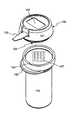
- FIG. 1is a perspective view of a first embodiment of an integrated system consistent with the present invention.
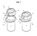
- FIG. 2is a perspective view of a second embodiment of an integrated system consistent with the present invention.
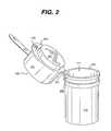
- FIG. 3is a perspective view of a third embodiment of an integrated system consistent with the present invention.
- FIG. 4is a cross-sectional view of a fourth embodiment of an integrated system consistent with the present invention.
- FIG. 5is a perspective view of a fifth embodiment of an integrated system consistent with the present invention.
- FIG. 6is a perspective view of a sixth embodiment of an integrated system consistent with the present invention.
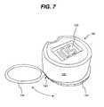
- FIG. 7is a perspective view of a meter housing comprising a holder configured to receive one or more devices used for diagnostic testing.
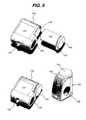
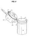
- FIG. 8is a perspective view of a container with a light emitting diode located on the container.
- FIG. 9is a perspective view of a container with a light emitting diode located on the meter.
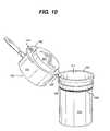
- FIG. 10is a perspective view of a container with a light emitting diode positioned additionally to illuminate an exterior portion of the container.
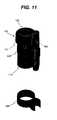
- FIG. 11is a perspective view of a holder in the form of a clip placed around a container.
- FIG. 12is a perspective view of a holder in the form of holes used to contain a container and a lancing device.
- FIG. 13is a cross-sectional view of a seventh embodiment of an integrated system consistent with the present invention.
- FIG. 14is a perspective view of a conductive coding pattern attached to a test strip container with a removable meter.
- FIG. 15is a perspective view of a conductive coding pattern attached to a test strip container inserted into a meter receptacle.
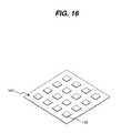
- FIG. 16is a perspective view of a substrate with several coded contact pads.
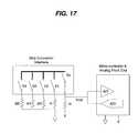
- FIG. 17is a perspective view of an analog code interface with a negative level trigger wake-up.
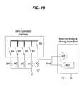
- FIG. 18is a perspective view of an analog code interface with a positive level trigger wake-up.
- FIG. 19is a perspective view of a digital code contact pad meter interface.
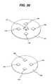
- FIG. 20is a top and bottom view of a memory chip on a printed circuit board with contact pads.
- FIG. 21is a perspective view of a memory chip on a printed circuit board with contact pads and a removable meter attached to a bottom portion of a test strip container.
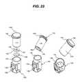
- FIG. 22is a perspective view of a memory chip on a printed circuit board with contact pads and a removable meter attached to a top portion of a test strip container.
- FIG. 23is a perspective view of a memory chip on a printed circuit board with contact pads attached to a bottom portion of a test strip container inserted into a meter receptacle.
- FIG. 24is a perspective view of a radio frequency identification tag in close proximity to a removable meter and attached to a top portion of a test strip container.
- FIG. 25is a perspective view of a radio frequency identification tag in close proximity to a removable meter and attached to a bottom portion of a test strip container.
- FIG. 26is a perspective view of a radio frequency identification tag in close proximity to a meter and attached to a bottom portion of a test strip container inserted into a meter receptacle.
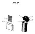
- FIG. 27is a perspective view of a foil pouch with a desiccant pill used to refill a refillable test strip container.
- FIG. 28is a perspective view of a coding element attached to a side portion of a container.
- FIG. 29is a perspective view of the meter keyed to align with the container with alignment features.
- FIG. 1is an integrated system 100 for conducting a diagnostic test in accordance with an exemplary embodiment of the present invention.
- Exemplary integrated system 100includes a container 110 for containing test media, such as test strips 120 , and a meter 130 for performing a diagnostic test using the test strips 120 contained in container 110 .
- the diagnostic testis the determination of the amount of glucose in a sample of whole blood applied to a sample chamber 121 of test strip 120 , as depicted in FIG. 3 .
- meter 130may employ any of a variety of techniques.
- the diagnostic testemploys an electrochemical technique (e.g., coulometry, amperometry, potentiometry, etc.). Exemplary electrochemical systems are described in prior U.S. Pat. No. 6,743,635, issued Jun. 1, 2004, and U.S. Pat. No. 6,946,299, issued Sep.
- meter 130may employ a photometric technique (e.g., reflection, transmission, scattering, absorption, fluorescence, electro-chemiluminescence, etc.) to determine the amount of glucose in the sample.
- a photometric techniquee.g., reflection, transmission, scattering, absorption, fluorescence, electro-chemiluminescence, etc.
- Exemplary photometric systemsare described in U.S. Pat. Nos. 6,201,607, 6,284,550 and 6,541,266, each commonly-assigned with the instant application, which are incorporated by reference herein in their entirety.
- electrochemical techniquesare currently preferred because, among other reasons, they require a smaller blood sample (on the order of 1 ⁇ L or less) than the photometric techniques (on the order of 1 ⁇ L or greater). Further, the instrumentation for the electrochemical techniques typically requires less power and can typically be made more compactly than the instrumentation for the photometric techniques.
- Integrated system 100will be illustrated with reference to a diagnostic test to determine the concentration of blood glucose using an electrochemical technique, with the understanding that the principles of the present invention are equally applicable to other types of diagnostic tests and techniques, such as those mentioned above.
- the present inventionhas been illustrated as utilizing test media in the form of test strips 120 , exemplary embodiments of the present invention are not limited to a particular type of media and those of skill in the art will recognize that the principles of the present invention are equally applicable to diagnostic testing systems which employ test media in other forms, e.g., tabs, discs, etc.
- Meter 130may be contained within a housing 131 .
- the meter housing 131is attached to or otherwise includes a closure portion 140 (bottom of meter 130 in FIG. 1 ) which engages container 110 in order to selectively close an opening 111 of the container.
- attachedmay be used to signify affiliated with, associated with, affixed with/to, connected with/to, coupled with/to, fastened with/to, fixed with/to, secured with/to, etc.
- a bottom portion of container 110may be attached to meter housing 131 by means of a retainer clip, screw thread, snap, or other retaining methods (not shown) or may be inserted into receptacle 145 of meter housing 131 in a keyed locating position, wherein the meter 130 is keyed to align with the container 110 with alignment features 152 and 154 such that it lines up with the code placement in order for the container to be read accurately ( FIGS. 5 and 29 ).
- the coding element and the meterare inherently aligned in a predetermined orientation with respect to each other.
- meter housing 131 with receptacle 145can additionally receive coded devices such as media players, terrestrial or satellite radios, travel alarm clocks, test alarms, PDAs, cell phones, memo voice recorders or other add-on functionality, such that a code, similar to the one placed on container 110 , can be read in order for the device to be used in conjunction with meter 130 .
- coded devicessuch as media players, terrestrial or satellite radios, travel alarm clocks, test alarms, PDAs, cell phones, memo voice recorders or other add-on functionality, such that a code, similar to the one placed on container 110 , can be read in order for the device to be used in conjunction with meter 130 .
- meter housing 131may include one or more buttons 132 implemented by a user control function to turn on meter 130 or eject container 110 after use. As illustrated in FIG. 5 , button 132 may be comfortably pressed with the right thumb or index finger while the integrated system 100 is held in the right hand, with display 133 in an upright position. However, button 132 may be positioned elsewhere on meter 130 . For example, button 132 may be placed on a right hand side of the meter housing 131 in order to be more convenient for left handed users ( FIG. 27 ) or on a top portion of the meter 130 .
- Meter housing 131may additionally include a holder 144 that is configured to receive one or more containers 110 , as illustrated in FIG. 7 .
- Holder 144is configured to be stored underneath closure 140 when not in use and is slidably movable (as illustrated by the position arrow) to a side position of the container 110 in order to receive and hold additional containers 110 .
- meter housing 131has one side (e.g., the bottom of meter housing 131 in FIG. 1 ) which is shaped to conform to the closure 140 and is affixed to the closure 140 , e.g., by a mechanical attachment (clips, etc.), bonding, gluing, welding, etc.
- closure portion 140may be formed integrally with the meter housing 131 . The meter 130 and closure 140 together thus form a cap or lid for the container 110 .
- the closure 140may be configured to engage the container in a number of ways. In the closed position (see FIGS. 3 and 4 ), closure 140 closes opening 111 sufficiently to prevent loss or removal of the test media from container 110 . Accordingly, closure 140 is configured to engage container 110 so as to prevent test strips 120 from passing through opening 111 when closure 140 is in the closed position. Container 110 and closure 140 may also be configured to prevent the infiltration of light, liquid, vapor, and/or air into the container 110 so as to prevent contamination or degradation of the test media. Where the test media is configured such that it is toxic or may present a choking hazard, closure 140 may optionally be configured to be child-resistant in order to prevent children from opening container 110 and accessing the test media. For example, closure 140 and container 110 may be configured in a manner similar to well known child-resistant containers for pharmaceuticals or household chemicals.
- Closure 140may be configured as a twist-off cap, e.g., by providing inter-engaging threads (not shown) on the closure 140 and the container 110 .
- closure 140may be configured to slide over the opening, e.g., within grooves (not shown) beside the opening.
- closure 140may be provided with a catch (not shown), such as a detent, that engages container 110 (or vice versa). The catch may be released by a button.
- the closure 140is configured to form a press-fit seal with the container so as to seal the opening against the infiltration of light, liquid and vapor. For example, in FIG.
- closure 140is configured with a recess (not shown) to press-fit to the outside of the opening 111 , so that the rim of the opening 111 fits within the closure portion 140 .
- closure 140may be configured with a projection 241 shaped to engage the inside of the opening 111 , as shown in FIG. 2 .
- the present inventionis not limited to any particular configuration of the container and closure and that other configurations may be employed consistent with the principles of the present invention.
- opening 111may be made in the same shape as the container 110 .
- the housing 131 of meter 130will also have an exterior shape similar to that of the container 110 so that the integrated system 100 may be more comfortably held and carried, e.g., in a user's pocket.
- the container 110 , meter 130 and opening 111need not be of the same exterior shape, and the container 110 and meter 130 may be configured in different shapes without departing from the scope of the present invention.
- the container 110is generally a right circular cylinder and opening 111 has a circular shape as shown in FIGS. 1 and 2 .
- a circular shapeis one possible configuration for the opening because it allows a uniformly tight seal to be formed with a press-fit between the closure portion 140 and the container 110 .
- meter 130may also be generally circular and cylindrical and have a width similar to the width of the container so that the integrated system 100 has an overall generally circular-cylindrical shape that is comfortable to hold and to carry, e.g., in a user's pocket.
- the container 110 , meter 130 and opening 111may be made in any of a number of other shapes.
- the containermay formed as a right oval, elliptical or rectangular cylinder in order to better conform to a user's shirt pocket.
- Custom shapesare also possible, and the container can be customized with graphical designs appealing to individual users, or the corporate logos of co-branding partners, etc.
- container 110 and closure 140may also be provided with corresponding flanges 112 and 242 , respectively, that fit flush against each other when the closure portion is in the closed position in order to further prevent the infiltration of liquid and vapor.
- Closure 140is also illustratively provided with a protrusion 143 which extends beyond the side of container 110 sufficiently aid to the user in opening and closing the container 110 , e.g., by pushing upward with the thumb against the protrusion 143 .
- Protrusion 143may be an extension of the flange 242 .
- protrusion 143may be formed directly on meter housing 131 , as shown in FIG. 3 .
- container 110may be opened by completely removing meter 130 and closure portion 140 from the container 110 .
- meter 130 and/or closure 140may be connected to container 110 in order to prevent the meter 130 from becoming separated from the container 110 ( FIG. 2 ).
- Container 110 and meter 130may be connected by, e.g., a hinge, lanyard or other flexible connector, such as a flexible plastic band or wire, etc. (not shown).
- a hinge 251connects the container 110 and the meter housing 131 and/or closure 140 . Hinge 251 is positioned such that projection 241 fits within opening 111 in the closed position.
- the connectormay have one end connected to the container 110 and the other end connected to the closure 140 and/or meter housing 131 .
- container 110 and closure 140may be integrally connected by a hinge, as is known in the art.
- one end of the connectore.g., hinge 251
- Ring 252may be configured to loosely and frictionally engage container 110 .
- ring 252may be affixed to the container 110 , e.g., by welding, gluing, etc.
- container 110may include a light emitting diode (LED) 253 that automatically or selectively illuminates the contents of the container 110 when it is opened.
- the LED 253may positioned on the container 110 , on the meter housing 131 , or positioned additionally to illuminate an exterior portion of the container 110 , as illustrated in FIGS. 8-10 .
- container 110 and closure 140are formed of polypropylene using an injection molding process.
- other materials and processesmay be used without departing from the scope of the present invention.
- Integrated system 100may further include a sampling device which the user may use to obtain a sample for testing.
- the sampling devicemay be adapted to obtain a biological sample.
- the sampling devicemay include a lancing device that the user can use to draw blood, e.g., for a diagnostic test of blood glucose level.
- Exemplary lancing device 360includes a rearward body 312 , a finger cover 314 , an exterior nozzle 318 , an interior nozzle 322 and a trigger 324 .
- Exemplary lancing device 360further includes an internal spring (not shown) that is used to propel lancet 320 beyond contact surface 321 and through the skin to a depth selected by the user.
- the exemplary lancing device 360is connected to container 110 .
- Lancing device 360may be permanently connected to the container, for instance, by forming, e.g., rearward body 312 , finger cover 314 , exterior nozzle 318 or interior nozzle 322 integrally with the container 110 , or by bonding one of these components to the container 110 , e.g., by a mechanical attachment (clips, brackets, tabs, slots), bonding, gluing, and welding.
- lancing device 360may be releasably connected to the container 110 by providing corresponding releasable connectors on lancing device 360 and container 110 .
- lancing device 360may be provided with one or more slots, holes, cavities, enclosures, or clips that engage corresponding structures on container 110 , or vice versa.
- a holder clip 608can be stretched over container 110 for a snug fit.
- Holder clip 608includes a clip that can releasably engage lancing device 360 in place.
- FIG. 12embodies holder holes 610 designed to engage the container 110 and the lancing device 360 together on one attachment.
- holderscan be used to receive one or more devices used for diagnostic testing, such as brackets, magnets, bayonet locks, slots, tabs, hook and loop fasteners, etc.
- lancing device 360may be connected to housing 131 of meter 130 , or to closure portion 140 .
- lancing device 360may be adjusted and used without disconnecting it from the container 110 .
- the usermay first select a desired depth of penetration of lancet 320 by rotating exterior nozzle 318 so that the desired depth indicator 326 on exterior nozzle 318 is aligned with arrow 328 on interior nozzle 322 .
- the userloads the internal spring by pulling interior nozzle 322 away from rearward body 312 and places contact surface 321 against the surface to be lanced.
- the usermay then actuate trigger 324 to release the internal spring, which propels lancet 320 beyond contact surface 321 to the indicated depth, and thus into the skin.
- a blood samplecan then be applied to the sample chamber 121 of test strip 120 .
- exemplary lancing device 360Further details of exemplary lancing device 360 are shown in prior application Ser. No. 10/757,776, entitled “LANCING DEVICE,” filed Jan. 15, 2004, commonly-assigned with the instant application, which is incorporated by reference herein in its entirety.
- the present inventionis not limited to any particular sampling device, and one of skill in the art will recognize that other sampling devices can be incorporated in a manner similar to the exemplary lancing device described above.
- Meter 130may be calibrated for use with a particular brand or manufacturer's lot of test media by customizing the diagnostic test performed by meter 130 with respect to the particular brand or lot using one or more calibration parameters.
- These calibration parametersmay include environmental corrections (e.g., temperature corrections), timing period corrections (e.g., with respect to incubation time), voltage corrections (e.g., for use in electrochemical tests), color variations (e.g., for use in photometric tests), etc., that customize the diagnostic test function of a controller (not shown) to the particular brand or lot of test media. See, e.g., U.S. Pat. Nos. 6,743,635 and 6,946,299, incorporated by reference above.
- integrated system 100includes one or more containers 110 or magazines 510 of test strips 120 packaged together with a meter 130 ( FIG. 13 ).
- the test strips 120 in the packageare from the same manufacturing lot or otherwise have the same characteristic reaction to blood glucose so that meter 130 may be calibrated once and thereafter used with any of the test strips 120 in the package without recalibration.
- Magazine 510may have an interior shape similar to that of the test media in order to maintain the alignment of the stack. For example, for the test strips 120 depicted in FIG. 1 , the interior of magazine 510 may be generally rectangular in cross-section.
- Dispensing mechanism 460in conjunction with detector 412 , dispenses the top test strip 125 in the stack using a linear and/or rotational mechanical action.
- the mechanical actionmay be executed manually (e.g., by the user pulling a slide or rotating a wheel) or by a motor (e.g., a stepper motor) actuated by a user control function.
- the top test strip 125is slid from the stack and through slot 520 .
- the test media used with this embodimentmay be modified by application of a non-friction coating or film, such as PTFE, to one or both sides in order to ensure smooth ejection.
- the diagnostic test function of the packaged meter 130may be precalibrated by the manufacturer or distributor, e.g., by providing instructions and/or data customized to the associated test media.
- meter 130may be calibrated at the user level by requiring the user to calibrate the meter with respect to a particular brand or lot of test media prior to using the meter to conduct diagnostic tests.
- the usermay utilize user control or input/output functions to enter or download calibration data or a code from which a controller (not shown) may derive calibration data.
- each test media container 110(or a co-packaged group of containers from the same lot) may be provided with a data storage device that stores the calibration data electronically. See, e.g., U.S. Pat. Nos. 6,743,635 and 6,946,299, incorporated by reference above.
- the present inventionallows the meter 130 to be removed from the test strip container 110 and transferred to another container by using several different coding techniques that prevent erroneous results that could have serious consequences for the user if the meter 130 is incorrectly calibrated. As long as the meter is properly associated with a coding container for strips of a matched lot, the user does not need to take further action to program the meter.
- the different coding techniques and coding elementsmay be used to provide a variety of diagnostic tests, with each diagnostic test testing a distinctive analyte in a sample.
- on-container coding techniquesallow a larger range of code numbers to be encoded due to large space available on the top, bottom, and side portions of container 110 .
- the meter 130is keyed to align with the container 110 with alignment features 152 and 154 such that it lines up with the code placement in order for the container 110 to be read accurately.
- the coding element and the meterare inherently aligned in a predetermined orientation with respect to each other.
- the containercan also be pre-read prior to insertion in the meter. This method is non-technique dependent or evident to the user, eliminating common coding errors associated with forgetting to change the code chip or button code on older technologies. Strips are unlikely to be mixed among different containers due to container strip lot code association.
- the metercan be programmed not to perform a test unless a code is properly accessed by the meter beforehand.
- the on-container coding methodincludes an electrically conductive coding pattern placed on a substrate 147 and directly printed on the test strip container 110 or attached to the container 110 with an adhesive label, such that the meter 130 makes contact with the coding pattern when attached.
- the meter 130then reads selected electrical properties, e.g., resistance values, of the coding pattern.
- the electrical valuesare associated with a proper code group stored in the meter 130 for that particular test strip lot.
- the integrated system 100is designed such that container 110 can be used with a removable meter 130 or container 110 may be inserted into receptacle 145 of meter housing 131 in a keyed locating position, as described above in FIGS. 5 and 6 .
- the on-container coding methodis advantageous in that it can be applied to the test container 110 after manufacturing has fully packaged the test strips 120 in the containers 110 .
- One having ordinary skill in the artwill understand that other information can also be encoded on container 110 such as product type, test type, etc.
- the information that is stored on the container 110can be as complex as an entire set of parameters for lot calibration or as simple as a lot code index that is correlated to a lot calibration pre-programmed in the meter 130 .
- a substrate 147includes a coding pattern with sixteen contact pads 149 or coding bits, giving the possibility of selecting 2 ⁇ 10 16 (65535) coding numbers or sixteen bits of information.
- the code conductormay either be exposed or removed from substrate 147 , or a printed electrical insulation pattern can cover the conductive substrate to produce opened, closed, or resistive encoding.
- the interface to the coded contact pads 149can either be resistive and read in an analog style or digital and read as on or off switch closures.
- analog resistive on-container codingwhen the container 110 comes in contact with meter 130 , the meter 130 reads the resistance value patterns to select the proper code group in the meter 130 for that particular test strip lot.
- the analog methodrequires a preset resistive ladder (R, 2 R, 4 R, 8 R), as illustrated in FIGS. 17 and 18 , to be interconnected to the contact pads 149 such that permutations of printed non-conductive ink can be correlated to distinct lot code information using a voltage drop, resistance or current measurement. Resistors can also be printed in different values and read in a similar arrangement.
- the analog methodalso can be simultaneously used as the auto-on feature so long as each code has at least one contact pad 149 free of non-conductive ink, which can make a low impedance connection to wake-up meter 130 .
- FIGS. 17 and 18illustrate an analog code interface with a negative and positive level trigger wake-up, respectively.
- the analog voltage, resistance or current levelmay also be used to identify the test type, simulate a test, check the test strips 120 , or check the manufacturing tests being employed.
- a binary coded numberis encoded using the patterned conducts as switches to open or close a switch to represent a 1 or 0 value in the lot code. Similar to analog resistive coding, in digital conductive coding the coding pattern can be preprinted and attached to the container 110 or printed on the container 110 directly.
- a code contact pad meter interfaceincludes a microcontroller and analog front end with interrupts (Int) and an A/D converter, a plurality of resistors (R), and a strip connector interface with a plurality of switches (S 1 , S 2 , S 3 , S 4 , and S 5 ). When the container 110 is placed in contact with the meter 130 , meter 130 is turned-on via the plurality of interrupts, having at least one contact switch closed.
- each contact pad 149must be read as individual inputs, unlike the single input required by the analog method.
- the inputsneed to be wired together or connected to the interrupts of the microcontroller.
- Each codemust have at least one contact pad 149 free of non-conductive ink such that a low impedance connection can be made to wake-up the microcontroller.
- one contact pad 149can be dedicated solely to wake-up the meter 130 and indicate whether the test strip 120 or code print is in the correct position.
- a test strip 120is inserted into meter 130 , one contact switch is closed and the meter 130 wakes up by pulling the microcontroller's interrupt either high or low.
- the meter 130checks the voltage out (V out ) to determine the test type and reads the code bits to determine the code value.
- a code number or code statusis displayed on the liquid crystal display (LCD) 133 of the meter 130 for a moment before the meter goes back to sleep.
- the code value selected by the meter 130is associated to a stored set of coefficients in the meter's memory for use in test configuration.
- This codecan also be associated with other types of strip parameter information, i.e. code integrity, meter type, correct alignment position of the test strip container 110 with meter 130 , manufacturing meter quality control (QC) tests, etc.
- Manufacturing meter QC testscan be identified by insertion of an additional fixed resistor in the code circuit, instead of the normal resistance of the code conductor, to identify a special test.
- the voltage drop across the plurality of resistors (R)may be used to check whether contact resistance is valid or can be used in a resistive coding representation. For example, after the container 110 is placed in contact with meter 130 , meter 130 reads the contact resistance from the resistive contact pads 149 with the A/D converter to encode strip lot code information.
- the on-container coding methodincludes a coded memory chip 151 embedded or attached to the test strip container 110 .
- the coded chipcan be an electrically erasable programmable read-only memory (EEPROM). Embedding the memory chip 151 into container 110 permits storing the largest amount of information possible related to the strip lot coding parameters.
- the memory chip 151can be mounted to a printed circuit board (PCB) 153 , which is attached to the top, bottom, or side portions of the test strip container 110 .
- PCBprinted circuit board
- Coded memory chips 151are monetarily advantageous in that the more expensive meter component 130 may be reused many times, whereas the less expensive coded memory chip 151 can be discarded with the used test strip container 110 after use. Additionally, test strips 120 will not be mixed among different containers due to container strip lot code association.
- the embedded EEPROM memory chip 151can also be disabled when a preset number of tests are completed. One having ordinary skill in the art will understand that many other stored parameters may disable memory chip 151 , i.e. strip specific test parameters, manufacture, test type, etc.
- memory chip 151is mounted on PCB 153 with contact pads 149 for transferring or storing lot code information on each test strip container 110 .
- Removable meter 130 and PCB 153 with the coding informationmay be attached to the top or bottom portions of container 110 ( FIGS. 20-22 ).
- PCB 153can be attached to a bottom portion of the container 110 , which is then inserted into the receptacle 145 of meter housing 131 in a keyed locating position, as described above in FIGS. 5 and 6 and shown in FIG. 23 .
- the on-container coding methodmay include a radio frequency (RF) device 157 , such as a RF identification tag (RF ID tag) code or other near field communication (NFC) device, that contains lot calibration information.
- RF device 157can be embedded into the test strip container 110 itself or be applied as an RF label to the top, bottom, or side portions of container 110 .
- RF ID tag 157is shown in close proximity, approximately 0 to 1 mm, from meter 130 for coding the meter 130 with lot specific information. Removable meter 130 and RF ID tag 157 with the coding information may be attached to the top or bottom portions of container 110 ( FIGS. 24 and 25 ).
- the RF ID tag 157can be attached to the bottom portion of the container 110 , which is then inserted into the receptacle 145 of meter housing 131 in a keyed locating position, as described above in FIGS. 5 and 6 and shown in FIG. 26 .
- the lot calibration informationis wirelessly programmed into the device.
- the RF device 157allows the meter 130 to read the lot information from the container 110 wirelessly, eliminating the need for the user to code the meter 130 . It is important for the RF device 157 to be in close proximity to the meter 130 to reduce the amount of power needed to power the RF ID tag memory device 157 . Accordingly, the reduced power requirement allows the use of small batteries and small portable battery powered metering devices, making it more comfortable for the user to carry the integrated system in his pocket.
- RF ID tag 157When using RF ID tag 157 to code meter 130 with lot specific information, such information can be transferred directly into the meter's memory (not shown) so that the RF tag 157 is read only once on insertion or attachment, thus auto-coding the meter for use. This method is non-technique dependent or evident to the user, eliminating common coding errors associated with forgetting to change the code chip or button code on older technologies. Strips cannot be mixed among different containers due to container strip lot code association.
- the RF tag 157can be programmed quickly after manufacturing information is known. The RF tag 157 can also be disabled when a preset number of tests are completed.
- One having ordinary skill in the artwill understand that many other stored parameters may disable RF tag 157 , i.e. strip specific test parameters, manufacture, test type, etc.
- the integrated diagnostic test system 100further employs additional safeguards to minimize the chance that a user will mistakenly use meter 130 with test media from a brand or lot for which the meter 130 has not been calibrated.
- the integrated diagnostic system 100can include one or more preventive measures that may disable one or more functions of the meter upon the occurrence of certain triggering events.
- the preventive measuremay render meter 130 wholly inoperative after the meter 130 has been used for a certain period of time or quantity of tests, or with a certain quantity of test media. The meter 130 may then be simply disposed of or returned to the manufacturer for remanufacturing.
- the preventive measuremay render only the diagnostic testing function of a controller (not shown) inoperative, or simply prevent the meter from displaying the result of a diagnostic test. The user may then retain meter 130 in order to use its remaining functions.
- a controllernot shown
- One having ordinary skill in the artwill understand that many other safeguards may be employed to minimize and prevent meter calibration errors.
- exemplary integrated diagnostic test system 100includes a container 110 for containing test media, such as test strips 120 , and a meter 130 for performing a diagnostic test using the test strips 120 contained in container 110 .
- Integrated system 100may further include a foil pouch of test strips 159 with a desiccant pill 161 that can be used to refill test strip container 110 , thus saving the cost of replacing container 110 with attached meter 130 .
- the usercan simply purchase a foil pouch of test strips 159 with a desiccant pill 161 to refill container 110 when empty.
- This refill methodcan be used with any on-container coding method described above, including use with coded contact pads 147 , coded memory chips 151 , and RF ID tag devices 157 .
Landscapes
- Health & Medical Sciences (AREA)
- Engineering & Computer Science (AREA)
- Biomedical Technology (AREA)
- Life Sciences & Earth Sciences (AREA)
- Physics & Mathematics (AREA)
- Chemical & Material Sciences (AREA)
- Medicinal Chemistry (AREA)
- General Health & Medical Sciences (AREA)
- Molecular Biology (AREA)
- Urology & Nephrology (AREA)
- Biophysics (AREA)
- Food Science & Technology (AREA)
- Optics & Photonics (AREA)
- Analytical Chemistry (AREA)
- Biochemistry (AREA)
- Hematology (AREA)
- General Physics & Mathematics (AREA)
- Immunology (AREA)
- Pathology (AREA)
- Measurement Of The Respiration, Hearing Ability, Form, And Blood Characteristics Of Living Organisms (AREA)
- Investigating Or Analysing Materials By The Use Of Chemical Reactions (AREA)
- Sampling And Sample Adjustment (AREA)
- Automatic Analysis And Handling Materials Therefor (AREA)
- Investigating Or Analysing Biological Materials (AREA)
Abstract
Description
Claims (33)
Priority Applications (14)
| Application Number | Priority Date | Filing Date | Title |
|---|---|---|---|
| US11/373,284US8388905B2 (en) | 2006-03-13 | 2006-03-13 | Method and apparatus for coding diagnostic meters |
| AU2007227741AAU2007227741A1 (en) | 2006-03-13 | 2007-02-27 | Method and apparatus for coding diagnostic meters |
| BRPI0708627ABRPI0708627A8 (en) | 2006-03-13 | 2007-02-27 | diagnostic testing system and coding method |
| EP07751812.4AEP1996933B1 (en) | 2006-03-13 | 2007-02-27 | Apparatus for coding diagnostic meters |
| MX2008011603AMX2008011603A (en) | 2006-03-13 | 2007-02-27 | Method and apparatus for coding diagnostic meters. |
| TW096106764ATWI453411B (en) | 2006-03-13 | 2007-02-27 | Method and apparatus for coding diagnostic meters |
| JP2009500370AJP5634063B2 (en) | 2006-03-13 | 2007-02-27 | Diagnostic measuring instrument coding method and apparatus |
| PCT/US2007/005079WO2007108900A1 (en) | 2006-03-13 | 2007-02-27 | Method and apparatus for coding diagnostic meters |
| US11/930,862US8388906B2 (en) | 2006-03-13 | 2007-10-31 | Apparatus for dispensing test strips |
| US11/934,004US8940246B2 (en) | 2006-03-13 | 2007-11-01 | Method and apparatus for coding diagnostic meters |
| NO20084215ANO20084215L (en) | 2006-03-13 | 2008-10-08 | Method and apparatus for coding diagnostic painters |
| US14/568,508US9623412B2 (en) | 2006-03-13 | 2014-12-12 | Method and apparatus for coding diagnostic meters |
| US15/475,616US10814325B2 (en) | 2006-03-13 | 2017-03-31 | Method and apparatus for coding diagnostic meters |
| US17/036,875US11559810B2 (en) | 2006-03-13 | 2020-09-29 | Method and apparatus for coding diagnostic meters |
Applications Claiming Priority (1)
| Application Number | Priority Date | Filing Date | Title |
|---|---|---|---|
| US11/373,284US8388905B2 (en) | 2006-03-13 | 2006-03-13 | Method and apparatus for coding diagnostic meters |
Related Child Applications (2)
| Application Number | Title | Priority Date | Filing Date |
|---|---|---|---|
| US11/930,862Continuation-In-PartUS8388906B2 (en) | 2006-03-13 | 2007-10-31 | Apparatus for dispensing test strips |
| US11/934,004Continuation-In-PartUS8940246B2 (en) | 2006-03-13 | 2007-11-01 | Method and apparatus for coding diagnostic meters |
Publications (2)
| Publication Number | Publication Date |
|---|---|
| US20070212258A1 US20070212258A1 (en) | 2007-09-13 |
| US8388905B2true US8388905B2 (en) | 2013-03-05 |
Family
ID=38328835
Family Applications (1)
| Application Number | Title | Priority Date | Filing Date |
|---|---|---|---|
| US11/373,284Active2028-07-22US8388905B2 (en) | 2006-03-13 | 2006-03-13 | Method and apparatus for coding diagnostic meters |
Country Status (9)
| Country | Link |
|---|---|
| US (1) | US8388905B2 (en) |
| EP (1) | EP1996933B1 (en) |
| JP (1) | JP5634063B2 (en) |
| AU (1) | AU2007227741A1 (en) |
| BR (1) | BRPI0708627A8 (en) |
| MX (1) | MX2008011603A (en) |
| NO (1) | NO20084215L (en) |
| TW (1) | TWI453411B (en) |
| WO (1) | WO2007108900A1 (en) |
Cited By (12)
| Publication number | Priority date | Publication date | Assignee | Title |
|---|---|---|---|---|
| US20110247949A1 (en)* | 2008-12-02 | 2011-10-13 | Bayer Healthcare Llc | Analyte Sensor Container Systems With Sensor Elevator and Storage Methods |
| US20140311256A1 (en)* | 2013-04-22 | 2014-10-23 | Pressco Technology Inc. | Cap analysis technique |
| US20140312054A1 (en)* | 2012-12-13 | 2014-10-23 | Lifescan Scotland Limited | Dispenser for electrochemical sensors |
| US20160026911A1 (en)* | 2013-03-08 | 2016-01-28 | Cryogatt Systems Ltd | Rfid caps and lids |
| US9376708B2 (en) | 2013-03-13 | 2016-06-28 | Ascensia Diabetes Care Holdings Ag | Bottled glucose sensor with no handling |
| US9383332B2 (en) | 2013-09-24 | 2016-07-05 | Lifescan Scotland Limited | Analytical test strip with integrated battery |
| US9535030B2 (en) | 2009-09-30 | 2017-01-03 | Ascensia Diabetes Care Holdings Ag | Stackable electrochemical analyte sensors, systems and methods including same |
| US9546997B2 (en) | 2013-03-11 | 2017-01-17 | Ascensia Diabetes Care Holdings Ag | Strip grabber |
| US9623412B2 (en) | 2006-03-13 | 2017-04-18 | Trividia Health, Inc. | Method and apparatus for coding diagnostic meters |
| US11090228B2 (en)* | 2016-08-19 | 2021-08-17 | Becton Dickinson And Company | Adapter assembly for attachment to a bottle |
| US11559810B2 (en) | 2006-03-13 | 2023-01-24 | Trividia Health, Inc. | Method and apparatus for coding diagnostic meters |
| US12420283B2 (en)* | 2020-08-28 | 2025-09-23 | Kao Corporation | Specimen-preserving implement |
Families Citing this family (24)
| Publication number | Priority date | Publication date | Assignee | Title |
|---|---|---|---|---|
| US20060118639A1 (en)* | 2004-12-06 | 2006-06-08 | First Data Corporation | Punchout contactless transaction card |
| US8388905B2 (en) | 2006-03-13 | 2013-03-05 | Nipro Diagnostics, Inc. | Method and apparatus for coding diagnostic meters |
| US8388906B2 (en)* | 2006-03-13 | 2013-03-05 | Nipro Diagnostics, Inc. | Apparatus for dispensing test strips |
| US8029735B2 (en)* | 2006-08-14 | 2011-10-04 | Bayer Healthcare, Llc | System and method for transferring calibration data |
| US7918121B2 (en)* | 2006-08-14 | 2011-04-05 | Bayer Healthcare, Llc | Meter system designed to run singulated test sensors |
| WO2008076212A1 (en)* | 2006-12-13 | 2008-06-26 | Bayer Healthcare Llc | Biosensor with coded information and method for manufacturing the same |
| KR200436314Y1 (en)* | 2007-03-21 | 2007-07-26 | 강은순 | Urine test paper vending machine |
| US20080230554A1 (en)* | 2007-03-23 | 2008-09-25 | Randolph Maryann | Chewing gum dispenser |
| US9029157B2 (en)* | 2007-04-12 | 2015-05-12 | Nipro Diagnostics, Inc. | Error detection and rejection for a diagnostic testing system |
| RU2010108229A (en)* | 2007-08-06 | 2011-09-20 | БАЙЕР ХЕЛТКЭА ЭлЭлСи (US) | SYSTEM AND METHOD FOR AUTOMATIC CALIBRATION |
| US8001825B2 (en)* | 2007-11-30 | 2011-08-23 | Lifescan, Inc. | Auto-calibrating metering system and method of use |
| US20090205399A1 (en)* | 2008-02-15 | 2009-08-20 | Bayer Healthcare, Llc | Auto-calibrating test sensors |
| US20100012490A1 (en)* | 2008-07-15 | 2010-01-21 | Tien-Tsai Hsu | Test strip with optical identification patterns and test instrument using the same |
| US20100015006A1 (en)* | 2008-07-16 | 2010-01-21 | Tien-Tsai Hsu | Test strip with identification openings and test instrument using the same |
| WO2010007532A2 (en)* | 2008-07-17 | 2010-01-21 | Universal Biosensors Pty Ltd. | Automatic information transfer by color encoded fields |
| WO2010095442A1 (en)* | 2009-02-18 | 2010-08-26 | パナソニック株式会社 | Puncture tool, device for measuring biological sample and system for measuring biological sample |
| US20100294660A1 (en)* | 2009-03-13 | 2010-11-25 | Tyson Bioresearch, Inc. | Glucose Testing Device And Strips For Same |
| US9168526B2 (en) | 2009-06-19 | 2015-10-27 | Zbx Corporation | Hinged cap for diagnostic device |
| US20100326824A1 (en)* | 2009-06-24 | 2010-12-30 | Lifescan, Inc. | Analyte test strip with combination electrode contact and meter identification feature |
| WO2011066852A1 (en)* | 2009-12-02 | 2011-06-09 | Widex A/S | Method and apparatus for alerting a person carrying an eeg assembly |
| US9384650B2 (en) | 2011-07-27 | 2016-07-05 | Panasonic Healthcare Holdings Co., Ltd. | Organism sample measurement device and organism sample measurement sensor housing device |
| WO2015195487A1 (en)* | 2014-06-19 | 2015-12-23 | Bayer Healthcare Llc | Sensor clip for stacked sensor dispensing system, and system using the same |
| KR102601322B1 (en)* | 2015-08-11 | 2023-11-10 | 에프. 호프만-라 로슈 아게 | Encoded biosensors and methods of making and using them |
| CN107402310A (en)* | 2016-05-19 | 2017-11-28 | 杭州凯珥医疗科技有限公司 | A kind of detection means and method with identification function for in-vitro diagnosis instrument |
Citations (103)
| Publication number | Priority date | Publication date | Assignee | Title |
|---|---|---|---|---|
| US3582335A (en) | 1967-02-21 | 1971-06-01 | Polaroid Corp | Film unit having sensitive layer and receiving layer with common web for face to face contact |
| US3918910A (en) | 1973-07-31 | 1975-11-11 | Olympus Optical Co | System for detecting the particular chemical constituent of a fluid |
| US4064760A (en) | 1976-12-15 | 1977-12-27 | Ipco Hospital Supply Corporation | Sterile urine collection device |
| US4100559A (en) | 1977-01-03 | 1978-07-11 | Polaroid Corporation | Apparatus for packaging and for using self-developing photographic film |
| US4142863A (en) | 1978-06-05 | 1979-03-06 | Eastman Kodak Company | Article container for dispensing reagent slides |
| US4162736A (en) | 1977-11-16 | 1979-07-31 | Three Sisters Ranch Enterprises | Plastic cap and container construction |
| US4279861A (en) | 1979-05-09 | 1981-07-21 | Eastman Kodak Company | Cartridge discriminator for an automated analysis system |
| EP0059350A1 (en) | 1981-02-23 | 1982-09-08 | Shipley Company Inc. | Waste solution treatment module |
| EP0064691A1 (en) | 1981-05-13 | 1982-11-17 | Miles Laboratories, Inc. | Apparatus comprising a magazine retaining multiple flexible test strips and means for removing a single test strip, and method of dispensing such strips using this apparatus |
| US4834234A (en) | 1987-05-13 | 1989-05-30 | Boehringer Mannheim Gmbh | Container for test strips |
| US4911344A (en) | 1988-03-23 | 1990-03-27 | Tek-Aids Inc. | Strip dispenser box |
| US5102624A (en) | 1986-09-03 | 1992-04-07 | Fuji Photo Film Co., Ltd. | Chemical analysis apparatus |
| EP0255675B1 (en) | 1986-07-30 | 1992-05-13 | Hoechst Aktiengesellschaft | Single test strip delivering system |
| US5119830A (en) | 1991-04-03 | 1992-06-09 | Code Blue Medical Corporation | Analytical specimen cup with testing means |
| US5154889A (en) | 1986-08-07 | 1992-10-13 | Fuji Photo Film Co., Ltd. | Chemical analysis apparatus |
| US5244116A (en) | 1992-04-06 | 1993-09-14 | Leo Daniel W | Cosmetic sample dispenser with replaceable magazines |
| US5281395A (en) | 1990-12-27 | 1994-01-25 | Boehringer Manheim Gmbh | Test carrier analysis system |
| US5298425A (en) | 1992-02-13 | 1994-03-29 | Boehringer Mannheim Gmbh | Device for the positionally correct feeding of test strips to an analysis unit |
| WO1994029703A1 (en) | 1993-06-08 | 1994-12-22 | Boehringer Mannheim Corporation | Biosensing meter with pluggable memory key |
| US5489414A (en) | 1993-04-23 | 1996-02-06 | Boehringer Mannheim, Gmbh | System for analyzing compounds contained in liquid samples |
| US5505308A (en) | 1993-08-27 | 1996-04-09 | Boehringer Mannheim Gmbh | System for the storage of test elements |
| US5510266A (en) | 1995-05-05 | 1996-04-23 | Bayer Corporation | Method and apparatus of handling multiple sensors in a glucose monitoring instrument system |
| EP0732590A2 (en) | 1995-03-14 | 1996-09-18 | Bayer Corporation | Dispensing instrument for fluid monitoring sensors |
| US5575403A (en) | 1995-01-13 | 1996-11-19 | Bayer Corporation | Dispensing instrument for fluid monitoring sensors |
| US5609823A (en) | 1993-08-05 | 1997-03-11 | Boehringer Mannheim Gmbh | System for the analysis of sample liquids |
| EP0779226A1 (en) | 1995-12-14 | 1997-06-18 | Roche Diagnostics GmbH | Storage container for strip-shaped test elements |
| WO1997029847A1 (en) | 1996-02-13 | 1997-08-21 | Selfcare, Inc. | Improved glucose monitor and test strip containers for use in same |
| US5660791A (en) | 1996-06-06 | 1997-08-26 | Bayer Corporation | Fluid testing sensor for use in dispensing instrument |
| US5714123A (en) | 1996-09-30 | 1998-02-03 | Lifescan, Inc. | Protective shield for a blood glucose strip |
| US5797693A (en) | 1995-05-02 | 1998-08-25 | Asulab S.A. | Apparatus intended for dispensing successive zones of a disposable strip |
| US5810199A (en) | 1996-06-10 | 1998-09-22 | Bayer Corporation | Dispensing instrument for fluid monitoring sensor |
| US5856195A (en)* | 1996-10-30 | 1999-01-05 | Bayer Corporation | Method and apparatus for calibrating a sensor element |
| US5872713A (en) | 1996-10-30 | 1999-02-16 | Mercury Diagnostics, Inc. | Synchronized analyte testing system |
| US5989197A (en) | 1996-03-07 | 1999-11-23 | Gallini S.R.L. | Automatic biopsy needle device |
| EP1022565A2 (en) | 1999-01-23 | 2000-07-26 | Roche Diagnostics GmbH | Method and device for withdrawing analytical consumables from a storage container |
| US6168957B1 (en) | 1997-06-25 | 2001-01-02 | Lifescan, Inc. | Diagnostic test strip having on-strip calibration |
| US6176119B1 (en) | 1997-12-13 | 2001-01-23 | Roche Diagnostics Gmbh | Analytical system for sample liquids |
| WO2001023885A1 (en) | 1999-09-27 | 2001-04-05 | Hypoguard Limited | Test device |
| US6283982B1 (en)* | 1999-10-19 | 2001-09-04 | Facet Technologies, Inc. | Lancing device and method of sample collection |
| WO2002008753A2 (en) | 2000-07-20 | 2002-01-31 | Hypoguard Limited | Device for measuring analyte concentration in a fluid |
| US6377894B1 (en) | 1998-11-30 | 2002-04-23 | Abbott Laboratories | Analyte test instrument having improved calibration and communication processes |
| US20020057993A1 (en) | 2000-08-30 | 2002-05-16 | Hypoguard Limited | Test device |
| US6398067B1 (en) | 1999-11-10 | 2002-06-04 | Cv Holdings, Llc | Tamper-proof container cap assembly and related methods |
| US20020076349A1 (en) | 2000-07-20 | 2002-06-20 | Hypoguard Limited | Test device |
| WO2002055008A2 (en) | 2000-12-29 | 2002-07-18 | Capitol Insulated Products, Inc. | Meter strip dispenser assembly |
| US6428664B1 (en) | 2000-06-19 | 2002-08-06 | Roche Diagnostics Corporation | Biosensor |
| WO2002078533A2 (en) | 2001-03-29 | 2002-10-10 | Inverness Medical Limited | Integrated sample testing meter |
| US6472220B1 (en) | 1997-12-04 | 2002-10-29 | Agilent Technologies, Inc. | Method of using cassette of lancet cartridges for sampling blood |
| US6488828B1 (en) | 2000-07-20 | 2002-12-03 | Roche Diagnostics Corporation | Recloseable biosensor |
| US20020188224A1 (en) | 2001-06-08 | 2002-12-12 | Roe Jeffrey N. | Test media cassette for bodily fluid testing device |
| US6508380B1 (en) | 1999-12-23 | 2003-01-21 | Alfred Von Schuckmann | Dispenser for the dispensing elements in strips |
| US20030031591A1 (en) | 2001-08-13 | 2003-02-13 | Whitson Robert C. | Sensor release for a blood glucose sensor dispensing instrument |
| US20030031595A1 (en) | 2001-08-13 | 2003-02-13 | Kirchhevel G. Lamar | Blood glucose sensor dispensing instrument having a modular electronics assembly |
| US20030032190A1 (en) | 2001-08-13 | 2003-02-13 | Brown Michael K. | Mechanical mechanism for a blood glucose sensor dispensing instrument |
| US20030036200A1 (en) | 2001-08-20 | 2003-02-20 | Charlton Steven C. | Packaging system for test sensors |
| EP1286162A2 (en) | 2001-08-13 | 2003-02-26 | Bayer Corporation | Blood glucose sensor dispensing instrument having a pull/push activation mechanism |
| US6534017B1 (en) | 1997-04-11 | 2003-03-18 | Roche Diagnostics Gmbh | Test element storage device |
| US20030059350A1 (en) | 1998-04-24 | 2003-03-27 | Klaus-Dieter Sacherer | Storage container for analytical devices |
| US6558528B1 (en) | 2000-12-20 | 2003-05-06 | Lifescan, Inc. | Electrochemical test strip cards that include an integral dessicant |
| US20030089730A1 (en) | 2001-11-14 | 2003-05-15 | May Stuart R. | Sensor dispensing device |
| WO2003042691A1 (en) | 2001-11-14 | 2003-05-22 | Hypoguard Limited | Sensor dispensing device |
| US20030116583A1 (en) | 2001-12-21 | 2003-06-26 | Pugh Jerry T. | Test device with means for storing and dispensing diagnostic strips |
| US20030129346A1 (en) | 1998-11-13 | 2003-07-10 | 3M Innovative Properties Company | Tape strip pads and dispenser and method of dispensing individual tape strips |
| US20030133847A1 (en)* | 2002-01-16 | 2003-07-17 | Robert Hagen | Test strip dispenser |
| US20030175155A1 (en) | 2002-03-18 | 2003-09-18 | Bayer Healthcare, Llc | Storage cartridge for biosensors |
| US20030178437A1 (en) | 2002-03-22 | 2003-09-25 | 3M Innovative Properties Company | Dispenser for tape strip pads |
| US20030185705A1 (en) | 2002-04-02 | 2003-10-02 | Gary Otake | Analyte concentration determination meters and methods of using the same |
| US20030185708A1 (en) | 2002-04-02 | 2003-10-02 | Gary Otake | Test strip containers and methods of using the same |
| US20030186446A1 (en) | 2002-04-02 | 2003-10-02 | Jerry Pugh | Test strip containers and methods of using the same |
| WO2003082092A1 (en) | 2002-04-02 | 2003-10-09 | Inverness Medical Limited | Test strip vial |
| WO2003082091A2 (en) | 2002-04-02 | 2003-10-09 | Inverness Medical Limited | Integrated sample testing meter |
| US20030203498A1 (en) | 2002-04-25 | 2003-10-30 | Home Diagnostics, Inc. | System and methods for blood glucose sensing |
| US20030212345A1 (en) | 2002-05-09 | 2003-11-13 | Mcallister Devin | Minimal procedure analyte test system |
| US20030212344A1 (en) | 2002-05-09 | 2003-11-13 | Vadim Yuzhakov | Physiological sample collection devices and methods of using the same |
| US20030211619A1 (en) | 2002-05-09 | 2003-11-13 | Lorin Olson | Continuous strip of fluid sampling and testing devices and methods of making, packaging and using the same |
| US20030223906A1 (en) | 2002-06-03 | 2003-12-04 | Mcallister Devin | Test strip container system |
| WO2004011068A1 (en) | 2002-07-25 | 2004-02-05 | Glaxo Group Limited | Medicament dispenser |
| US20040038411A1 (en) | 2002-08-21 | 2004-02-26 | Hayter Paul G. | Diagnostic kit with a memory storing test strip calibration codes and related methods |
| US20040048394A1 (en) | 2001-08-13 | 2004-03-11 | Bayer Corporation | Button layout for a testing instrument |
| US20040057878A1 (en) | 2000-08-11 | 2004-03-25 | Allen House | Strip holder for use in a test strip meter |
| WO2004041082A1 (en) | 2002-11-01 | 2004-05-21 | Pelikan Technologies, Inc. | Method and apparatus for body fluid sampling |
| WO2004041672A2 (en) | 2002-11-02 | 2004-05-21 | Glaxo Group Limited | Blister package for inhalable medicament |
| WO2004044142A2 (en) | 2002-11-05 | 2004-05-27 | The Brigham And Women's Hospital, Inc. | Mesenchymal stem cells and methods of use thereof |
| US20040178216A1 (en) | 2003-01-14 | 2004-09-16 | David Brickwood | Sensor dispensing device |
| US20050019953A1 (en) | 2003-06-20 | 2005-01-27 | Henning Groll | System and method for coding information on a biosensor test strip |
| US20050023137A1 (en)* | 2003-06-20 | 2005-02-03 | Bhullar Raghbir S. | Biosensor with multiple electrical functionalities |
| WO2005040793A1 (en) | 2003-10-15 | 2005-05-06 | Inverness Medical Limited | Meter and test sensor bank incorporating re-writable memory |
| US20050143675A1 (en) | 2003-12-31 | 2005-06-30 | Home Diagnostics, Inc. | Integrated diagnostic test system |
| DE102004062255B3 (en) | 2004-12-23 | 2006-02-16 | Roche Diagnostics Gmbh | Portable process and assembly to determine and record blood sugar level for diabetics has test strip container with hinge flip electronic counter |
| US20060094986A1 (en) | 2003-12-31 | 2006-05-04 | Home Diagnostics, Inc. | Test strip container with integrated meter |
| US7070053B1 (en) | 2000-09-05 | 2006-07-04 | Cv Holdings Llc | System, method, and apparatuses for maintaining, tracking, transporting and identifying the integrity of a disposable specimen container with a re-usable transponder |
| WO2006076721A2 (en) | 2005-01-14 | 2006-07-20 | Bayer Healthcare Llc | Test sensor cartridges and sensor-dispensing instruments |
| US20060189895A1 (en) | 2003-12-31 | 2006-08-24 | Neel Gary T | Test strip container with integrated meter having strip coding capability |
| US20060275890A1 (en) | 2005-06-06 | 2006-12-07 | Home Diagnostics, Inc. | Method of manufacturing a disposable diagnostic meter |
| US7213720B2 (en) | 2002-10-10 | 2007-05-08 | Csp Technologies, Inc. | Resealable moisture tight containers for strips and the like |
| EP1806588A1 (en) | 2004-10-29 | 2007-07-11 | Arkray, Inc. | Analyzer, cartridge, and analysis kit |
| WO2007085438A2 (en) | 2006-01-26 | 2007-08-02 | Roche Diagnostic Gmbh | Stack magazine system |
| WO2007090662A1 (en) | 2006-02-10 | 2007-08-16 | Roche Diagnostics Gmbh | Personal portable blood glucose meter with replaceable cartridge of test strips |
| WO2007108900A1 (en) | 2006-03-13 | 2007-09-27 | Home Diagnostics, Inc. | Method and apparatus for coding diagnostic meters |
| US7276027B2 (en) | 2001-02-06 | 2007-10-02 | Roche Diagnostics Operations, Inc. | System, for monitoring the concentration of analytes in body fluids |
| US20080118400A1 (en) | 2006-03-13 | 2008-05-22 | Neel Gary T | Apparatus For Dispensing Test Strips |
| WO2008063405A1 (en) | 2006-11-20 | 2008-05-29 | Bayer Healthcare Llc | Test-sensor cartridge |
| US20080134810A1 (en) | 2006-03-13 | 2008-06-12 | Home Diagnostics, Inc. | Method and apparatus for coding diagnostic meters |
Family Cites Families (3)
| Publication number | Priority date | Publication date | Assignee | Title |
|---|---|---|---|---|
| US5865195A (en)* | 1997-07-03 | 1999-02-02 | Carter; Theresa | Oral hygiene system |
| US6814844B2 (en)* | 2001-08-29 | 2004-11-09 | Roche Diagnostics Corporation | Biosensor with code pattern |
| US7316929B2 (en)* | 2002-09-10 | 2008-01-08 | Bayer Healthcare Llc | Auto-calibration label and apparatus comprising same |
- 2006
- 2006-03-13USUS11/373,284patent/US8388905B2/enactiveActive
- 2007
- 2007-02-27BRBRPI0708627Apatent/BRPI0708627A8/ennot_activeApplication Discontinuation
- 2007-02-27WOPCT/US2007/005079patent/WO2007108900A1/enactiveApplication Filing
- 2007-02-27AUAU2007227741Apatent/AU2007227741A1/ennot_activeAbandoned
- 2007-02-27TWTW096106764Apatent/TWI453411B/enactive
- 2007-02-27EPEP07751812.4Apatent/EP1996933B1/enactiveActive
- 2007-02-27JPJP2009500370Apatent/JP5634063B2/enactiveActive
- 2007-02-27MXMX2008011603Apatent/MX2008011603A/enactiveIP Right Grant
- 2008
- 2008-10-08NONO20084215Apatent/NO20084215L/enunknown
Patent Citations (129)
| Publication number | Priority date | Publication date | Assignee | Title |
|---|---|---|---|---|
| US3582335A (en) | 1967-02-21 | 1971-06-01 | Polaroid Corp | Film unit having sensitive layer and receiving layer with common web for face to face contact |
| US3918910A (en) | 1973-07-31 | 1975-11-11 | Olympus Optical Co | System for detecting the particular chemical constituent of a fluid |
| US4064760A (en) | 1976-12-15 | 1977-12-27 | Ipco Hospital Supply Corporation | Sterile urine collection device |
| US4100559A (en) | 1977-01-03 | 1978-07-11 | Polaroid Corporation | Apparatus for packaging and for using self-developing photographic film |
| US4162736A (en) | 1977-11-16 | 1979-07-31 | Three Sisters Ranch Enterprises | Plastic cap and container construction |
| US4142863A (en) | 1978-06-05 | 1979-03-06 | Eastman Kodak Company | Article container for dispensing reagent slides |
| US4279861A (en) | 1979-05-09 | 1981-07-21 | Eastman Kodak Company | Cartridge discriminator for an automated analysis system |
| EP0059350A1 (en) | 1981-02-23 | 1982-09-08 | Shipley Company Inc. | Waste solution treatment module |
| EP0064691A1 (en) | 1981-05-13 | 1982-11-17 | Miles Laboratories, Inc. | Apparatus comprising a magazine retaining multiple flexible test strips and means for removing a single test strip, and method of dispensing such strips using this apparatus |
| EP0064691B1 (en) | 1981-05-13 | 1986-03-05 | Miles Laboratories, Inc. | Apparatus comprising a magazine retaining multiple flexible test strips and means for removing a single test strip, and method of dispensing such strips using this apparatus |
| EP0255675B1 (en) | 1986-07-30 | 1992-05-13 | Hoechst Aktiengesellschaft | Single test strip delivering system |
| US5154889A (en) | 1986-08-07 | 1992-10-13 | Fuji Photo Film Co., Ltd. | Chemical analysis apparatus |
| US5102624A (en) | 1986-09-03 | 1992-04-07 | Fuji Photo Film Co., Ltd. | Chemical analysis apparatus |
| US4834234A (en) | 1987-05-13 | 1989-05-30 | Boehringer Mannheim Gmbh | Container for test strips |
| US4911344A (en) | 1988-03-23 | 1990-03-27 | Tek-Aids Inc. | Strip dispenser box |
| US5281395A (en) | 1990-12-27 | 1994-01-25 | Boehringer Manheim Gmbh | Test carrier analysis system |
| US5119830A (en) | 1991-04-03 | 1992-06-09 | Code Blue Medical Corporation | Analytical specimen cup with testing means |
| US5298425A (en) | 1992-02-13 | 1994-03-29 | Boehringer Mannheim Gmbh | Device for the positionally correct feeding of test strips to an analysis unit |
| US5244116A (en) | 1992-04-06 | 1993-09-14 | Leo Daniel W | Cosmetic sample dispenser with replaceable magazines |
| US5489414A (en) | 1993-04-23 | 1996-02-06 | Boehringer Mannheim, Gmbh | System for analyzing compounds contained in liquid samples |
| US5863800A (en) | 1993-04-23 | 1999-01-26 | Boehringer Mannheim Gmbh | Storage system for test elements |
| US5720924A (en) | 1993-04-23 | 1998-02-24 | Boehringer Mannheim Gmbh | Storage system for test elements |
| EP0622119B1 (en) | 1993-04-23 | 1999-11-03 | Roche Diagnostics GmbH | System for storing and dispensing test elements |
| WO1994029703A1 (en) | 1993-06-08 | 1994-12-22 | Boehringer Mannheim Corporation | Biosensing meter with pluggable memory key |
| US5679311A (en) | 1993-08-05 | 1997-10-21 | Boehringer Mannheim Gmbh | System for the analysis of sample liquids |
| US5609823A (en) | 1993-08-05 | 1997-03-11 | Boehringer Mannheim Gmbh | System for the analysis of sample liquids |
| US5505308A (en) | 1993-08-27 | 1996-04-09 | Boehringer Mannheim Gmbh | System for the storage of test elements |
| US5630986A (en) | 1995-01-13 | 1997-05-20 | Bayer Corporation | Dispensing instrument for fluid monitoring sensors |
| US5575403A (en) | 1995-01-13 | 1996-11-19 | Bayer Corporation | Dispensing instrument for fluid monitoring sensors |
| EP0732590A3 (en) | 1995-03-14 | 1997-05-21 | Bayer Ag | Sensor dispenser for liquid analysis |
| US5854074A (en) | 1995-03-14 | 1998-12-29 | Bayer Corporation | Dispensing instrument for fluid monitoring sensors |
| EP0732590A2 (en) | 1995-03-14 | 1996-09-18 | Bayer Corporation | Dispensing instrument for fluid monitoring sensors |
| US5797693A (en) | 1995-05-02 | 1998-08-25 | Asulab S.A. | Apparatus intended for dispensing successive zones of a disposable strip |
| US5510266A (en) | 1995-05-05 | 1996-04-23 | Bayer Corporation | Method and apparatus of handling multiple sensors in a glucose monitoring instrument system |
| EP0779226A1 (en) | 1995-12-14 | 1997-06-18 | Roche Diagnostics GmbH | Storage container for strip-shaped test elements |
| US5989917A (en) | 1996-02-13 | 1999-11-23 | Selfcare, Inc. | Glucose monitor and test strip containers for use in same |
| WO1997029847A1 (en) | 1996-02-13 | 1997-08-21 | Selfcare, Inc. | Improved glucose monitor and test strip containers for use in same |
| EP1225448A2 (en) | 1996-02-13 | 2002-07-24 | Inverness Medical Technology, Inc. | Improved glucose monitor and test strip containers for use in same |
| US5989197A (en) | 1996-03-07 | 1999-11-23 | Gallini S.R.L. | Automatic biopsy needle device |
| US5660791A (en) | 1996-06-06 | 1997-08-26 | Bayer Corporation | Fluid testing sensor for use in dispensing instrument |
| US5810199A (en) | 1996-06-10 | 1998-09-22 | Bayer Corporation | Dispensing instrument for fluid monitoring sensor |
| US5714123A (en) | 1996-09-30 | 1998-02-03 | Lifescan, Inc. | Protective shield for a blood glucose strip |
| US5856195A (en)* | 1996-10-30 | 1999-01-05 | Bayer Corporation | Method and apparatus for calibrating a sensor element |
| US20030219357A1 (en) | 1996-10-30 | 2003-11-27 | Douglas Joel S. | Synchronized analyte testing system |
| US6106780A (en) | 1996-10-30 | 2000-08-22 | Amira Medical | Synchronized analyte testing system |
| US6544475B1 (en) | 1996-10-30 | 2003-04-08 | Amira Medical | Synchronized analyte testing system |
| US5872713A (en) | 1996-10-30 | 1999-02-16 | Mercury Diagnostics, Inc. | Synchronized analyte testing system |
| US6534017B1 (en) | 1997-04-11 | 2003-03-18 | Roche Diagnostics Gmbh | Test element storage device |
| US6682704B2 (en) | 1997-04-11 | 2004-01-27 | Roche Diagnostics Corporation | Magazine for storing test elements |
| US6168957B1 (en) | 1997-06-25 | 2001-01-02 | Lifescan, Inc. | Diagnostic test strip having on-strip calibration |
| US6472220B1 (en) | 1997-12-04 | 2002-10-29 | Agilent Technologies, Inc. | Method of using cassette of lancet cartridges for sampling blood |
| US6176119B1 (en) | 1997-12-13 | 2001-01-23 | Roche Diagnostics Gmbh | Analytical system for sample liquids |
| US20030059350A1 (en) | 1998-04-24 | 2003-03-27 | Klaus-Dieter Sacherer | Storage container for analytical devices |
| US20030129346A1 (en) | 1998-11-13 | 2003-07-10 | 3M Innovative Properties Company | Tape strip pads and dispenser and method of dispensing individual tape strips |
| US6377894B1 (en) | 1998-11-30 | 2002-04-23 | Abbott Laboratories | Analyte test instrument having improved calibration and communication processes |
| EP1022565A2 (en) | 1999-01-23 | 2000-07-26 | Roche Diagnostics GmbH | Method and device for withdrawing analytical consumables from a storage container |
| WO2001023885A1 (en) | 1999-09-27 | 2001-04-05 | Hypoguard Limited | Test device |
| US6283982B1 (en)* | 1999-10-19 | 2001-09-04 | Facet Technologies, Inc. | Lancing device and method of sample collection |
| US6398067B1 (en) | 1999-11-10 | 2002-06-04 | Cv Holdings, Llc | Tamper-proof container cap assembly and related methods |
| US6508380B1 (en) | 1999-12-23 | 2003-01-21 | Alfred Von Schuckmann | Dispenser for the dispensing elements in strips |
| US6428664B1 (en) | 2000-06-19 | 2002-08-06 | Roche Diagnostics Corporation | Biosensor |
| US6488828B1 (en) | 2000-07-20 | 2002-12-03 | Roche Diagnostics Corporation | Recloseable biosensor |
| US20020076349A1 (en) | 2000-07-20 | 2002-06-20 | Hypoguard Limited | Test device |
| WO2002008753A2 (en) | 2000-07-20 | 2002-01-31 | Hypoguard Limited | Device for measuring analyte concentration in a fluid |
| US7138089B2 (en) | 2000-07-20 | 2006-11-21 | Hypoguard Limited | Test device for analyzing blood glucose or other analytes in bodily fluids |
| US20030047451A1 (en) | 2000-07-20 | 2003-03-13 | Bhullar Raghbir Singh | Recloseable biosensor |
| US20040057878A1 (en) | 2000-08-11 | 2004-03-25 | Allen House | Strip holder for use in a test strip meter |
| US20020057993A1 (en) | 2000-08-30 | 2002-05-16 | Hypoguard Limited | Test device |
| US7070053B1 (en) | 2000-09-05 | 2006-07-04 | Cv Holdings Llc | System, method, and apparatuses for maintaining, tracking, transporting and identifying the integrity of a disposable specimen container with a re-usable transponder |
| US6558528B1 (en) | 2000-12-20 | 2003-05-06 | Lifescan, Inc. | Electrochemical test strip cards that include an integral dessicant |
| US7063234B2 (en) | 2000-12-29 | 2006-06-20 | Csp Technologies, Inc. | Meter strip dispenser assembly |
| US20020104849A1 (en) | 2000-12-29 | 2002-08-08 | Jean-Pierre Giruad | Meter strip dispenser assembly |
| WO2002055008A2 (en) | 2000-12-29 | 2002-07-18 | Capitol Insulated Products, Inc. | Meter strip dispenser assembly |
| US7276027B2 (en) | 2001-02-06 | 2007-10-02 | Roche Diagnostics Operations, Inc. | System, for monitoring the concentration of analytes in body fluids |
| WO2002078533A2 (en) | 2001-03-29 | 2002-10-10 | Inverness Medical Limited | Integrated sample testing meter |
| US20030191415A1 (en) | 2001-03-29 | 2003-10-09 | Piet Moerman | Integrated sample testing meter |
| US20020188224A1 (en) | 2001-06-08 | 2002-12-12 | Roe Jeffrey N. | Test media cassette for bodily fluid testing device |
| US20030031595A1 (en) | 2001-08-13 | 2003-02-13 | Kirchhevel G. Lamar | Blood glucose sensor dispensing instrument having a modular electronics assembly |
| US20040048394A1 (en) | 2001-08-13 | 2004-03-11 | Bayer Corporation | Button layout for a testing instrument |
| US20030031591A1 (en) | 2001-08-13 | 2003-02-13 | Whitson Robert C. | Sensor release for a blood glucose sensor dispensing instrument |
| US20030032190A1 (en) | 2001-08-13 | 2003-02-13 | Brown Michael K. | Mechanical mechanism for a blood glucose sensor dispensing instrument |
| EP1286162A2 (en) | 2001-08-13 | 2003-02-26 | Bayer Corporation | Blood glucose sensor dispensing instrument having a pull/push activation mechanism |
| US20030036200A1 (en) | 2001-08-20 | 2003-02-20 | Charlton Steven C. | Packaging system for test sensors |
| EP1285695A2 (en) | 2001-08-20 | 2003-02-26 | Bayer Corporation | Packaging system for test sensors |
| US20030089730A1 (en) | 2001-11-14 | 2003-05-15 | May Stuart R. | Sensor dispensing device |
| WO2003042691A1 (en) | 2001-11-14 | 2003-05-22 | Hypoguard Limited | Sensor dispensing device |
| US20030116583A1 (en) | 2001-12-21 | 2003-06-26 | Pugh Jerry T. | Test device with means for storing and dispensing diagnostic strips |
| EP1329395A1 (en) | 2002-01-16 | 2003-07-23 | Lifescan, Inc. | Test strip dispenser |
| US20030133847A1 (en)* | 2002-01-16 | 2003-07-17 | Robert Hagen | Test strip dispenser |
| US20030175155A1 (en) | 2002-03-18 | 2003-09-18 | Bayer Healthcare, Llc | Storage cartridge for biosensors |
| US20030178437A1 (en) | 2002-03-22 | 2003-09-25 | 3M Innovative Properties Company | Dispenser for tape strip pads |
| WO2003082091A2 (en) | 2002-04-02 | 2003-10-09 | Inverness Medical Limited | Integrated sample testing meter |
| WO2003083469A2 (en) | 2002-04-02 | 2003-10-09 | Inverness Medical Limited | Integrated sample testing meter |
| EP1362801A2 (en) | 2002-04-02 | 2003-11-19 | Lifescan, Inc. | Test strip containers and methods of using the same |
| US20030185705A1 (en) | 2002-04-02 | 2003-10-02 | Gary Otake | Analyte concentration determination meters and methods of using the same |
| US20030185708A1 (en) | 2002-04-02 | 2003-10-02 | Gary Otake | Test strip containers and methods of using the same |
| WO2003082092A1 (en) | 2002-04-02 | 2003-10-09 | Inverness Medical Limited | Test strip vial |
| US20040007585A1 (en)* | 2002-04-02 | 2004-01-15 | Griffith Alun W. | Test strip vial |
| US20030186446A1 (en) | 2002-04-02 | 2003-10-02 | Jerry Pugh | Test strip containers and methods of using the same |
| US20030203498A1 (en) | 2002-04-25 | 2003-10-30 | Home Diagnostics, Inc. | System and methods for blood glucose sensing |
| US20030211619A1 (en) | 2002-05-09 | 2003-11-13 | Lorin Olson | Continuous strip of fluid sampling and testing devices and methods of making, packaging and using the same |
| US20030212344A1 (en) | 2002-05-09 | 2003-11-13 | Vadim Yuzhakov | Physiological sample collection devices and methods of using the same |
| US20030212345A1 (en) | 2002-05-09 | 2003-11-13 | Mcallister Devin | Minimal procedure analyte test system |
| EP1369083A1 (en) | 2002-06-03 | 2003-12-10 | Lifescan, Inc. | Test strip container system |
| US20030223906A1 (en) | 2002-06-03 | 2003-12-04 | Mcallister Devin | Test strip container system |
| WO2004011068A1 (en) | 2002-07-25 | 2004-02-05 | Glaxo Group Limited | Medicament dispenser |
| US20040038411A1 (en) | 2002-08-21 | 2004-02-26 | Hayter Paul G. | Diagnostic kit with a memory storing test strip calibration codes and related methods |
| US7213720B2 (en) | 2002-10-10 | 2007-05-08 | Csp Technologies, Inc. | Resealable moisture tight containers for strips and the like |
| WO2004041082A1 (en) | 2002-11-01 | 2004-05-21 | Pelikan Technologies, Inc. | Method and apparatus for body fluid sampling |
| WO2004041672A2 (en) | 2002-11-02 | 2004-05-21 | Glaxo Group Limited | Blister package for inhalable medicament |
| WO2004044142A2 (en) | 2002-11-05 | 2004-05-27 | The Brigham And Women's Hospital, Inc. | Mesenchymal stem cells and methods of use thereof |
| US20040178216A1 (en) | 2003-01-14 | 2004-09-16 | David Brickwood | Sensor dispensing device |
| US20050019953A1 (en) | 2003-06-20 | 2005-01-27 | Henning Groll | System and method for coding information on a biosensor test strip |
| US20050023137A1 (en)* | 2003-06-20 | 2005-02-03 | Bhullar Raghbir S. | Biosensor with multiple electrical functionalities |
| WO2005040793A1 (en) | 2003-10-15 | 2005-05-06 | Inverness Medical Limited | Meter and test sensor bank incorporating re-writable memory |
| US20060094986A1 (en) | 2003-12-31 | 2006-05-04 | Home Diagnostics, Inc. | Test strip container with integrated meter |
| US20050143675A1 (en) | 2003-12-31 | 2005-06-30 | Home Diagnostics, Inc. | Integrated diagnostic test system |
| US20060189895A1 (en) | 2003-12-31 | 2006-08-24 | Neel Gary T | Test strip container with integrated meter having strip coding capability |
| EP1806588A1 (en) | 2004-10-29 | 2007-07-11 | Arkray, Inc. | Analyzer, cartridge, and analysis kit |
| DE102004062255B3 (en) | 2004-12-23 | 2006-02-16 | Roche Diagnostics Gmbh | Portable process and assembly to determine and record blood sugar level for diabetics has test strip container with hinge flip electronic counter |
| WO2006076721A2 (en) | 2005-01-14 | 2006-07-20 | Bayer Healthcare Llc | Test sensor cartridges and sensor-dispensing instruments |
| US20060275890A1 (en) | 2005-06-06 | 2006-12-07 | Home Diagnostics, Inc. | Method of manufacturing a disposable diagnostic meter |
| WO2007050396A1 (en) | 2005-10-21 | 2007-05-03 | Home Diagnostics, Inc. | Test strip container with integrated meter having strip coding capability |
| WO2007085438A2 (en) | 2006-01-26 | 2007-08-02 | Roche Diagnostic Gmbh | Stack magazine system |
| WO2007090662A1 (en) | 2006-02-10 | 2007-08-16 | Roche Diagnostics Gmbh | Personal portable blood glucose meter with replaceable cartridge of test strips |
| WO2007108900A1 (en) | 2006-03-13 | 2007-09-27 | Home Diagnostics, Inc. | Method and apparatus for coding diagnostic meters |
| US20080118400A1 (en) | 2006-03-13 | 2008-05-22 | Neel Gary T | Apparatus For Dispensing Test Strips |
| US20080134810A1 (en) | 2006-03-13 | 2008-06-12 | Home Diagnostics, Inc. | Method and apparatus for coding diagnostic meters |
| WO2008063405A1 (en) | 2006-11-20 | 2008-05-29 | Bayer Healthcare Llc | Test-sensor cartridge |
Non-Patent Citations (10)
| Title |
|---|
| International Search Report and Written Opinion for PCT/US2008/081691, mailed Jan. 29, 2009. |
| International Search Report and Written Opinion, PCT/US2007/005079, dated Sep. 3, 2007. |
| International Search Report mailed Oct. 8, 2009 from the European Patent Office in corresponding Application No. PCT/US2008/081432. |
| Japanese Patent Office Office Action mailed Feb. 14, 2012, in application 2009-500370, 7 pages. |
| Office Action mailed Apr. 29, 2009, in co-pending U.S. Appl. No. 11/930,862, filed Oct. 31, 2007. |
| Office Action mailed Jan. 26, 2010, in co-pending U.S. Appl. No. 11/930,862, filed Oct. 31, 2007. |
| Office Action mailed Mar. 15, 2010, in co-pending U.S. Appl. No. 11/930,862, filed Oct. 31, 2007. |
| Office Action mailed Nov. 25, 2009, in co-pending U.S. Appl. No. 11/930,862, filed Oct. 31, 2007. |
| Office Action mailed Sep. 14, 2010 in co-pending U.S. Appl. No. 11/934,004, filed Nov. 1, 2007. |
| XP-002397571, "ACCU-CHEK® Compact Plus User's Manual," Roche Diagnostics GmbH, Jan. 2005. |
Cited By (18)
| Publication number | Priority date | Publication date | Assignee | Title |
|---|---|---|---|---|
| US11559810B2 (en) | 2006-03-13 | 2023-01-24 | Trividia Health, Inc. | Method and apparatus for coding diagnostic meters |
| US10814325B2 (en) | 2006-03-13 | 2020-10-27 | Trividia Health, Inc. | Method and apparatus for coding diagnostic meters |
| US9623412B2 (en) | 2006-03-13 | 2017-04-18 | Trividia Health, Inc. | Method and apparatus for coding diagnostic meters |
| US8684172B2 (en)* | 2008-12-02 | 2014-04-01 | Bayer Healthcare Llc | Analyte sensor container systems with sensor elevator and storage methods |
| US20110247949A1 (en)* | 2008-12-02 | 2011-10-13 | Bayer Healthcare Llc | Analyte Sensor Container Systems With Sensor Elevator and Storage Methods |
| US9535030B2 (en) | 2009-09-30 | 2017-01-03 | Ascensia Diabetes Care Holdings Ag | Stackable electrochemical analyte sensors, systems and methods including same |
| US20140312054A1 (en)* | 2012-12-13 | 2014-10-23 | Lifescan Scotland Limited | Dispenser for electrochemical sensors |
| US20160026911A1 (en)* | 2013-03-08 | 2016-01-28 | Cryogatt Systems Ltd | Rfid caps and lids |
| US10748050B2 (en)* | 2013-03-08 | 2020-08-18 | Cryogatt Systems Limited | RFID caps and lids |
| US9546997B2 (en) | 2013-03-11 | 2017-01-17 | Ascensia Diabetes Care Holdings Ag | Strip grabber |
| US10132791B2 (en) | 2013-03-13 | 2018-11-20 | Ascensia Diagnostics Care Holdings AG | Bottled glucose sensor with no handling |
| US9376708B2 (en) | 2013-03-13 | 2016-06-28 | Ascensia Diabetes Care Holdings Ag | Bottled glucose sensor with no handling |
| US10871483B2 (en) | 2013-03-13 | 2020-12-22 | Ascensia Diabetes Care Holdings Ag | Bottled glucose sensor with no handling |
| US9417145B2 (en)* | 2013-04-22 | 2016-08-16 | Pressco Technology Inc. | Cap analysis technique |
| US20140311256A1 (en)* | 2013-04-22 | 2014-10-23 | Pressco Technology Inc. | Cap analysis technique |
| US9383332B2 (en) | 2013-09-24 | 2016-07-05 | Lifescan Scotland Limited | Analytical test strip with integrated battery |
| US11090228B2 (en)* | 2016-08-19 | 2021-08-17 | Becton Dickinson And Company | Adapter assembly for attachment to a bottle |
| US12420283B2 (en)* | 2020-08-28 | 2025-09-23 | Kao Corporation | Specimen-preserving implement |
Also Published As
| Publication number | Publication date |
|---|---|
| JP2009530608A (en) | 2009-08-27 |
| NO20084215L (en) | 2008-12-11 |
| EP1996933B1 (en) | 2019-05-29 |
| TW200745549A (en) | 2007-12-16 |
| BRPI0708627A2 (en) | 2011-06-07 |
| TWI453411B (en) | 2014-09-21 |
| US20070212258A1 (en) | 2007-09-13 |
| BRPI0708627A8 (en) | 2019-01-15 |
| JP5634063B2 (en) | 2014-12-03 |
| EP1996933A1 (en) | 2008-12-03 |
| AU2007227741A1 (en) | 2007-09-27 |
| WO2007108900A1 (en) | 2007-09-27 |
| MX2008011603A (en) | 2008-09-22 |
Similar Documents
| Publication | Publication Date | Title |
|---|---|---|
| US8388905B2 (en) | Method and apparatus for coding diagnostic meters | |
| US8388906B2 (en) | Apparatus for dispensing test strips | |
| US8394328B2 (en) | Test strip container with integrated meter having strip coding capability | |
| US8394337B2 (en) | Test strip container with integrated meter | |
| US10814325B2 (en) | Method and apparatus for coding diagnostic meters | |
| EP1706024B1 (en) | Integrated diagnostic test system | |
| US11559810B2 (en) | Method and apparatus for coding diagnostic meters | |
| BRPI0617361B1 (en) | diagnostic test systems and method of determining the level of a constituent in a fluid |
Legal Events
| Date | Code | Title | Description |
|---|---|---|---|
| AS | Assignment | Owner name:HOME DIAGNOSTICS, INC., FLORIDA Free format text:ASSIGNMENT OF ASSIGNORS INTEREST;ASSIGNORS:NEEL, GARY T.;MODZELEWSKI, BRENT E.;ROUNDS, GEORGE;AND OTHERS;REEL/FRAME:017676/0887;SIGNING DATES FROM 20060306 TO 20060307 Owner name:HOME DIAGNOSTICS, INC., FLORIDA Free format text:ASSIGNMENT OF ASSIGNORS INTEREST;ASSIGNORS:NEEL, GARY T.;MODZELEWSKI, BRENT E.;ROUNDS, GEORGE;AND OTHERS;SIGNING DATES FROM 20060306 TO 20060307;REEL/FRAME:017676/0887 | |
| AS | Assignment | Owner name:NIPRO DIAGNOSTICS, INC., FLORIDA Free format text:CHANGE OF NAME;ASSIGNOR:HOME DIAGNOSTICS, INC.;REEL/FRAME:024678/0455 Effective date:20100607 | |
| AS | Assignment | Owner name:REGIONS BANK, FLORIDA Free format text:SECURITY AGREEMENT;ASSIGNOR:NIPRO DIAGNOSTICS, INC.;REEL/FRAME:028840/0948 Effective date:20120822 | |
| FEPP | Fee payment procedure | Free format text:PAYOR NUMBER ASSIGNED (ORIGINAL EVENT CODE: ASPN); ENTITY STATUS OF PATENT OWNER: LARGE ENTITY | |
| STCF | Information on status: patent grant | Free format text:PATENTED CASE | |
| AS | Assignment | Owner name:NIPRO DIAGNOSTICS, INC., FLORIDA Free format text:RELEASE BY SECURED PARTY;ASSIGNOR:REGIONS BANK;REEL/FRAME:031581/0955 Effective date:20131101 Owner name:WELLS FARGO BANK, NATIONAL ASSOCIATION, AS ADMINIS Free format text:SECURITY AGREEMENT;ASSIGNOR:NIPRO DIAGNOSTICS, INC.;REEL/FRAME:031580/0094 Effective date:20131101 | |
| AS | Assignment | Owner name:TRIVIDIA HEALTH, INC., FLORIDA Free format text:CHANGE OF NAME;ASSIGNOR:NIPRO DIAGNOSTICS, INC.;REEL/FRAME:038002/0867 Effective date:20160107 | |
| FPAY | Fee payment | Year of fee payment:4 | |
| MAFP | Maintenance fee payment | Free format text:PAYMENT OF MAINTENANCE FEE, 8TH YEAR, LARGE ENTITY (ORIGINAL EVENT CODE: M1552); ENTITY STATUS OF PATENT OWNER: LARGE ENTITY Year of fee payment:8 | |
| MAFP | Maintenance fee payment | Free format text:PAYMENT OF MAINTENANCE FEE, 12TH YEAR, LARGE ENTITY (ORIGINAL EVENT CODE: M1553); ENTITY STATUS OF PATENT OWNER: LARGE ENTITY Year of fee payment:12 |