US8388690B2 - Osteotomy system - Google Patents
Osteotomy systemDownload PDFInfo
- Publication number
- US8388690B2 US8388690B2US10/958,036US95803604AUS8388690B2US 8388690 B2US8388690 B2US 8388690B2US 95803604 AUS95803604 AUS 95803604AUS 8388690 B2US8388690 B2US 8388690B2
- Authority
- US
- United States
- Prior art keywords
- spacer
- bone
- osteotomy
- proximal
- distal
- Prior art date
- Legal status (The legal status is an assumption and is not a legal conclusion. Google has not performed a legal analysis and makes no representation as to the accuracy of the status listed.)
- Active, expires
Links
Images


Classifications
- A—HUMAN NECESSITIES
- A61—MEDICAL OR VETERINARY SCIENCE; HYGIENE
- A61B—DIAGNOSIS; SURGERY; IDENTIFICATION
- A61B17/00—Surgical instruments, devices or methods
- A61B17/14—Surgical saws
- A61B17/15—Guides therefor
- A61B17/151—Guides therefor for corrective osteotomy
- A61B17/152—Guides therefor for corrective osteotomy for removing a wedge-shaped piece of bone
- A—HUMAN NECESSITIES
- A61—MEDICAL OR VETERINARY SCIENCE; HYGIENE
- A61B—DIAGNOSIS; SURGERY; IDENTIFICATION
- A61B17/00—Surgical instruments, devices or methods
- A61B17/14—Surgical saws
- A61B17/15—Guides therefor
- A—HUMAN NECESSITIES
- A61—MEDICAL OR VETERINARY SCIENCE; HYGIENE
- A61B—DIAGNOSIS; SURGERY; IDENTIFICATION
- A61B17/00—Surgical instruments, devices or methods
- A61B17/16—Instruments for performing osteoclasis; Drills or chisels for bones; Trepans
- A61B17/17—Guides or aligning means for drills, mills, pins or wires
- A61B17/1728—Guides or aligning means for drills, mills, pins or wires for holes for bone plates or plate screws
- A—HUMAN NECESSITIES
- A61—MEDICAL OR VETERINARY SCIENCE; HYGIENE
- A61B—DIAGNOSIS; SURGERY; IDENTIFICATION
- A61B17/00—Surgical instruments, devices or methods
- A61B17/16—Instruments for performing osteoclasis; Drills or chisels for bones; Trepans
- A61B17/17—Guides or aligning means for drills, mills, pins or wires
- A61B17/1739—Guides or aligning means for drills, mills, pins or wires specially adapted for particular parts of the body
- A61B17/1764—Guides or aligning means for drills, mills, pins or wires specially adapted for particular parts of the body for the knee
- A—HUMAN NECESSITIES
- A61—MEDICAL OR VETERINARY SCIENCE; HYGIENE
- A61B—DIAGNOSIS; SURGERY; IDENTIFICATION
- A61B17/00—Surgical instruments, devices or methods
- A61B17/56—Surgical instruments or methods for treatment of bones or joints; Devices specially adapted therefor
- A61B17/58—Surgical instruments or methods for treatment of bones or joints; Devices specially adapted therefor for osteosynthesis, e.g. bone plates, screws or setting implements
- A61B17/68—Internal fixation devices, including fasteners and spinal fixators, even if a part thereof projects from the skin
- A61B17/80—Cortical plates, i.e. bone plates; Instruments for holding or positioning cortical plates, or for compressing bones attached to cortical plates
- A61B17/8095—Wedge osteotomy devices
- A—HUMAN NECESSITIES
- A61—MEDICAL OR VETERINARY SCIENCE; HYGIENE
- A61B—DIAGNOSIS; SURGERY; IDENTIFICATION
- A61B17/00—Surgical instruments, devices or methods
- A61B17/02—Surgical instruments, devices or methods for holding wounds open, e.g. retractors; Tractors
- A61B17/025—Joint distractors
Definitions
- the inventionrelates to an apparatus and procedure for surgically correcting joint alignment. More particularly, the invention relates to an apparatus and procedure for performing an osteotomy to correct knee alignment.
- a variety of conditionsmay negatively affect the human knee including arthritis, ligament instability, and localized trauma. These conditions may be surgically treated by repairing portions of the knee cartilage, meniscus, or ligaments or by replacing them with natural or artificial replacements. In such procedures, it is often necessary to correct the alignment of the knee to relieve pressure from the damaged portion of the joint and balance the load on the joint. In some instances, correcting the knee alignment alone, without additional repair or replacement of injured or diseased tissue, is sufficient to provide relief and improve function. Often, in a young arthritis patient, correcting the knee alignment may be a first surgical choice to provide years of relief prior to resorting to a more aggressive total knee replacement procedure. Typically, injured or diseased knees will develop a varus deformity in which the medial side of the person's knee joint has become compressed resulting in a bowlegged alignment of the lower limb.
- a frequently used procedure to correct knee alignmentis high tibial osteotomy.
- the knee alignmentis changed by cutting the tibia on one side and then expanding or compressing the cut side to change the angle between the axes of the tibia and femur.
- a wedge of boneis removed from the tibia and then the opposite sides of the cut are brought together to angle the tibia towards the side on which the cut was made.
- a cutis made partway across the tibia and the cut is opened to create a wedge-shaped gap thereby angling the tibia away from the side on which the cut was made.
- a fixturing devicesuch as a bone plate or external fixator, is then applied to the tibia to hold the tibial alignment until the bone heals.
- boneis taken from the patient's pelvis and applied to the gap in the tibia to aid in bone healing.
- An opening high tibial osteotomymay be performed on the medial side of a patient's knee to treat a varus deformity.
- a distal femoral osteotomyAnother procedure used to correct knee alignment is a distal femoral osteotomy. For example, in an opening lateral distal femoral osteotomy, a cut is made partway across the femur from the lateral side and the cut is opened to create a wedge-shaped gap thereby angling the femur away from the lateral side.
- the present inventionprovides a high tibial osteotomy (HTO) system including a wedge implant and an osteotomy guide.
- HTOhigh tibial osteotomy
- a wedge-shaped spacer for insertion into an osteotomyincludes a body having a first surface, a second surface, and an insertion axis.
- the first and second surfacesare angled relative to one another in a first plane containing the insertion axis by a first angle and the first and second surfaces are angled relative to one another in a second plane perpendicular to the insertion axis by a second angle.
- a wedge-shaped spacer for insertion into an osteotomyincludes a body having first and second surfaces and proximal and distal ends. The first and second surfaces are angled relative to one another and from the proximal end toward the distal end.
- the bodyincludes an opening extending through a portion of the body from near the distal end to near the proximal end and lying between the first and second surfaces over a portion of the length of the opening.
- the spacerfurther includes a threaded fastener inserted into the opening and engaging the spacer such that the fastener may be mounted on the bone and threaded into the spacer to translate the spacer distally.
- a wedge-shaped spacer for insertion into an osteotomyincludes a body having first and second converging surfaces and proximal and distal sidewalls.
- the spacerincludes an opening from the first surface to the second surface extending to the proximal sidewall to form a gap in the proximal sidewall such that the gap permits bone growth between the two bone portions at the proximal opening of the osteotomy.
- a wedge-shaped spacer for insertion into an osteotomyincludes a body having a first surface, a second surface, a proximal end, and a distal end. The first and second surfaces converge from the proximal end toward the distal end.
- the spacer bodyincludes a plurality of zones including one or more bioresorbable materials. The zones have different rates of bioresorption.
- a wedge-shaped spacer for insertion into an osteotomyincludes a body having a first surface, a second surface, a proximal end, and a distal end.
- the first and second surfacesare spaced further apart at a position adjacent to the proximal end than at a position adjacent to the distal end.
- At least one fixation plateextends from the proximal end transversely to the first and second surfaces.
- the fixation plateincludes at least one transverse hole configured to receive a bone screw and the fixation plate is formed from a relatively more malleable material than the spacer body.
- a wedge-shaped spacer for insertion into an osteotomy formed in a boneincludes a body having first and second surfaces and proximal and distal ends. The first and second surfaces converge from the proximal end toward the distal end.
- the bodyincludes a portal extending through a portion of the body from near the proximal end to the distal end and lying generally between the first and second surfaces.
- An inserterincludes a shaft having a proximal end and a distal end.
- the inserter shaftincludes an axial bore extending from the proximal end to the distal end.
- the distal end of the inserter shaftis engageable with the proximal end of the spacer in force transmitting relationship.
- a plungerengages the axial bore of the inserter shaft and is operable to expel material from the distal end of the inserter shaft into the portal in the spacer.
- An inserter for inserting a wedge-shaped spacer into an osteotomy formed in a boneincludes a shaft having a proximal end and a distal end. The distal end is engageable with the spacer in force transmitting relationship.
- a drill sleeve guideincludes a body mountable on the shaft and an elongated tab extending outwardly away from the drill sleeve guide body generally parallel to the fixation plate.
- the tabincludes an elongated through hole having a vertically oriented long axis. The vertical dimension of the elongated through hole is greater than the vertical dimension of the fixation plate through hole.
- a drill sleevehas a proximal end, a distal end, and a longitudinal through bore.
- the longitudinal through boreis sized to guide a drill.
- the drill sleeveis extendable through the elongated through hole of the drill sleeve guide such that the distal end of the drill sleeve engages the fixation plate through hole.
- the drill sleeveis then pivotable between a first angular position in which it abuts the top of the elongated through hole of the drill sleeve guide and the drill sleeve bore is normal to the fixation plate and a second angular position in which it abuts the bottom of the elongated through hole of the drill sleeve guide and the drill sleeve is directed at an angle away from the spacer body such that the drill sleeve can be angled to remain normal to the fixation plate if the fixation plate is bent toward the drill sleeve guide.
- the second clamping armopposes the first clamping arm and is mounted to the first clamping arm for relative translation.
- the armsare translatable between a first position in which they are spaced from opposite sides of the bone and a second position in which they abut opposite sides of the bone in clamping arrangement.
- the cutteris mounted to one of the first and second arms such that the cutter guide can guide a cutter to form the osteotomy in the bone at a predetermined orientation relative to the first and second clamping arms.
- an osteotomy guidein another aspect of the invention, includes a base having means for mounting it on the bone, a cutter guide, a drill guide, and a drill.
- the cutter guideis mounted to the base such that the cutter guide can guide a cutter to form the osteotomy in the bone at a predetermined orientation relative to the base.
- the drill guideis mounted to the base and includes a guide bore. The drill is received in the guide bore such that the drill guide can guide the drill to form a hole in the bone at the vertex of the osteotomy.
- a method of correcting the angular alignment of a boneincludes: creating an osteotomy in a bone in which the osteotomy partially divides the bone into two bone portions connected by a bony hinge, the osteotomy having a proximal opening at a cortical surface of the bone and a distal vertex adjacent the bony hinge; determining a required first angular correction in a first plane; determining a required second angular correction in a second plane; providing a wedge-shaped spacer comprising a body having first and second surfaces, the first and second surfaces being angled relative to one another in a third plane containing the insertion axis by a third angle, the first and second surfaces being angled relative to one another in a fourth plane by a fourth angle; and inserting the spacer into the osteotomy to simultaneously correct the bone alignment in the first and second planes.
- a method of correcting the angular alignment of a boneincludes: creating an osteotomy in a bone in which the osteotomy partially divides the bone into two bone portions connected by a bony hinge, the osteotomy having a proximal opening at a cortical surface of the bone and a distal vertex adjacent the bony hinge; determining at least one required angular correction in a first plane; providing a wedge-shaped spacer comprising a body having first and second surfaces, the first and second surfaces being angled relative to one another in a first plane containing the insertion axis by a first angle different from the value of the predetermined angular correction, the first and second surfaces being angled relative to one another in a second plane perpendicular to the insertion axis by a second angle different from the value of the predetermined angular correction; and inserting the spacer into the osteotomy obliquely such that bone alignment is corrected by the predetermined angular correction as a result of the combined effects of the
- a method of correcting the angular alignment of a boneincludes mounting a guide base on the bone; guiding a drill relative to the guide base to create a bone hole at a desired vertex for the angular correction; guiding a cutter relative to the guide base to create an osteotomy in the bone extending from a cortical surface of the bone to the bone hole; and opening the osteotomy to correct the angular alignment of the bone.
- a method of correcting the angular alignment of a boneincludes creating an osteotomy in a bone in which the osteotomy partially divides the bone into two bone portions connected by a bony hinge, the osteotomy having a proximal opening at a cortical surface of the bone and a distal vertex adjacent the bony hinge; engaging a wedge-shaped implant with an insertion tool; inserting the implant into the osteotomy with the insertion tool; and using the insertion tool as a syringe to inject bone growth promoting substances through the implant and into the vertex of the osteotomy.
- a method of correcting the angular alignment of a boneincludes: creating an osteotomy in a bone in which the osteotomy partially divides the bone into two bone portions connected by a bony hinge, the osteotomy having a proximal opening at a cortical surface of the bone and a distal vertex adjacent the bony hinge; inserting a wedge-shaped spacer into the osteotomy, the spacer comprising a body having first and second surfaces and proximal and distal sidewalls, the first and second surfaces being angled relative to one another in a first plane by a first angle, the first and second surfaces converging from the proximal sidewall toward the distal sidewall, the spacer including an opening from the first surface to the second surface and extending to the proximal sidewall forming a gap in the proximal sidewall such that the gap permits bone growth between the two bone portions at the proximal opening of the osteotomy; and permitting bone to grow through the gap in the proximal side
- a method of correcting the angular alignment of a boneincludes: creating an osteotomy in a bone in which the osteotomy partially divides the bone into two bone portions connected by a bony hinge, the osteotomy having a proximal opening in a medial cortical surface of the bone and a distal vertex adjacent the bony hinge near a lateral cortical surface; inserting a wedge implant into the osteotomy through the opening in the medial cortical surface; and inserting a fastener through the lateral cortical surface and into engagement with the implant.
- FIG. 1is a front elevation view of a tibia showing an illustrative high tibial osteotomy.
- FIG. 2 ais a perspective view of an illustrative wedge implant according to the present invention.
- FIG. 2 bis a perspective view of coordinate planes illustrating the relationship between the surfaces of the implant of FIG. 2 a.
- FIG. 3is a top plan view of the implant of FIG. 2 a.
- FIG. 4is a front elevation view of the implant of FIG. 2 a.
- FIG. 5is a side elevation view of the implant of FIG. 2 a.
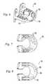
- FIG. 6is a perspective view of the implant of FIG. 2 a showing an alternative arrangement of bone growth promoting holes.
- FIG. 7is a top plan view of the implant of FIG. 6 .
- FIG. 8is a top plan view of the implant of FIG. 2 a showing an alternative arrangement of bone growth promoting holes.
- FIG. 9is a top plan view of the implant of FIG. 2 a showing an alternative arrangement of bone growth promoting holes.
- FIG. 10is a perspective view of the implant of FIG. 2 a showing an alternative arrangement of fixation holes for securing the implant to a bone.
- FIG. 11is a top plan view of the implant of FIG. 10 .
- FIG. 12is a side elevation view of the implant of FIG. 10 .
- FIG. 13is a side elevation view of the implant of FIG. 2 a showing an alternative arrangement of fixation holes for securing the implant to a bone.
- FIG. 14is a perspective view of the implant of FIG. 13 showing a fixation plate in use with the implant.
- FIG. 15is a perspective view of the implant of FIG. 2 a showing an alternative arrangement for a fixation plate for securing the implant to a bone.
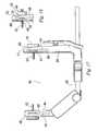
- FIG. 16is an exploded perspective view of an instrument for performing an osteotomy according to the present invention.
- FIG. 17is a top plan view of the instrument of FIG. 16 showing an alternative arrangement for attaching the instrument to a bone.
- FIG. 18is a detail top plan view showing a modification to the instrument of FIG. 17 .
- FIG. 19is a perspective view of the instrument of FIG. 16 shown attached to a bone and showing an alternative adjustment mechanism.
- FIG. 20is a front elevation view of the instrument of FIG. 19 .
- FIG. 21is a perspective view of the instrument of FIG. 19 .
- FIG. 22is another perspective view of the instrument of FIG. 19 .
- FIG. 23is a top plan view of the instrument of FIG. 16 showing an alternative modular component mounting.
- FIG. 24is a top plan view of the instrument of FIG. 23 showing another alternative modular component mounting.
- FIG. 25is a perspective view of the instrument of FIG. 23 showing an alternative means of attaching the instrument to a bone.
- FIG. 26is a top plan view of a dilator according to the present invention.
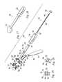
- FIG. 27is an exploded perspective view of an insertion instrument and drill guide according to the present invention.
- FIG. 28is a cross sectional detail view showing the use of the insertion instrument of FIG. 27 with the implant of FIG. 2 a.
- FIG. 29is a cross sectional detail view showing the use of the insertion instrument of FIG. 27 with the implant of FIG. 2 a.
- FIGS. 30-36depict steps in using the instruments of FIGS. 16 and 27 with the implant of FIG. 2 a.
- Examples of an osteotomy systeminclude a wedge implant and an osteotomy guide.
- the wedge implantmay include a wedge-shaped spacer that is inserted into an osteotomy in a bone to provide primary support to the osteotomy in an expanded position.
- the wedge implantmay include superior and inferior planar surfaces that are offset by a first angle in a first plane to provide an angular correction to the bone.
- the wedge implantmay interface at least partially with the bone surfaces of the osteotomy.
- the superior surface of the wedge implantmay be offset from the inferior surface by two angles to provide a dual correction.
- the first angleis as described above whereas the second angle lies in a second plane.
- a change in the posterior tibial slopemay be desired by the surgeon to restore the posterior tibial slope to an anatomically normal angle, to decrease the angle of posterior tibial slope for patients who have instability related to ACL deficiency, or for other surgical purposes.
- the second anglemay be provided to facilitate a less invasive surgical procedure in which the wedge implant is inserted into the osteotomy along a linear drive direction oblique to the osteotomy vertex.
- the wedge implantin a tibial osteotomy, may be inserted approximately normal to the anterior medial tibial cortex at the location of the osteotomy.
- the first and second anglesmay be sized to compensate for this oblique insertion direction such that the two angles cooperate to provide a correction only in the coronal plane.
- the anglesmay also be sized to provide a dual correction such that the two angles cooperate to provide both a coronal alignment correction and a sagittal alignment correction when the wedge implant is inserted obliquely.
- the wedge implantmay be shaped to support the osteotomy by at least partially engaging the cancellous bone within the osteotomy. It may further engage the cortical bone surrounding the osteotomy such as at the anterior medial cortex and/or the posterior cortex in a tibial osteotomy. Cortical engagement can better resist bending moments resulting from compressive loading of the bone.
- the wedge implantmay include a lip, or flange, to engage the cortical bone surface and act as a stop during insertion. This lip may extend onto the cortex, may conform to the cortical surface, and may function as a bone plate by featuring holes to receive bone screws through the cortex. Alternatively, the bone plate may be a separate piece.
- the bone platemay resist valgus loading, which would tend to open a medial tibial osteotomy, flexion-extension moments, rotational forces between the bone sections superior and inferior to the osteotomy, and extrusion of the wedge implant from the osteotomy.
- the bone platemay be made of a different material than the wedge implant.
- the wedge implantmay feature at least one cannulation that is aligned transversely to the vertex of the osteotomy in an axial view of the bone.
- the cannulationmay receive a bone screw that is inserted through the wedge implant, for example from medial to lateral, to engage the cortex opposite the osteotomy opening to prevent the wedge implant from extruding from the osteotomy under loading.
- the cannulationmay be directed such that it does not intersect the vertex of the osteotomy in order to prevent the bone screw from violating the remaining bone at the hinge point for the osteotomy.
- the wedge implantmay be pulled into the osteotomy to expand and support it.
- the wedge implantmay be pulled into place by one or more bone screws, or bolts, anchored to the opposite cortex. Screws may bear directly on the cortex or may abut a plate which bears on the cortex.
- the wedge implantmay have serrated superior and inferior surfaces to purchase into the bone surfaces within the osteotomy to prevent extrusion.
- the serrations alonemay adequately prevent extrusion for smaller amounts of correction, which would subject the wedge implant to generally lower extrusion forces; however, larger amounts of correction may require additional fixation such as the plate or bone screw described above for proper stabilization.
- the wedge implantmay be shaped to provide at least one opening between opposite sides of the osteotomy to allow bone to grow across the osteotomy.
- the openingmay be located adjacent to the osteotomy opening since bone growth at the osteotomy opening would provide the most mechanical leverage for resisting compressive and tensile loads across the osteotomy opening due to its relatively large distance from the osteotomy vertex.
- the opening in the spacermay also be shaped to accommodate a tibial tunnel for other procedures such as ACL or PCL reconstruction in a tibia with no or little removal of wedge implant material during the reconstruction drilling process.
- the wedge implantmay also feature micro- or macro-pores to allow bone in-growth, or through-holes or channels oriented to allow cancellous bone growth across the osteotomy.
- the pores and/or channelsmay contain bone growth promoting substances.
- the wedge implantmay also contain at least one channel oriented to allow injection or insertion of bone cement and/or bone growth promoting substances into the osteotomy after seating the implant.
- the wedge implantmay be made in a variety of sizes, corresponding to different amounts of angular correction determined by the surgeon to correct the misalignment.
- the wedge implantmay be shaped such that it is symmetric. This would enable one range of wedge implant sizes to be used in both left and right cases, and would decrease the amount of inventory required by the manufacturer and the end user.
- the wedge implant and/or the bone screws and/or the platemay be made of a non-resorbable or resorbable polymer, a metal, a ceramic, or a combination thereof.
- the materialmay further be solid, or have micro- or macro-pores, or have through holes or a combination thereof, for allowing in-growth of bone.
- the materialmay also contain bone growth promoting substances such as osteoconductive additives such as autograft bone, allograft bone, bone paste, demineralized bone matrix, beta tricalcium phosphate, hydroxyapatite, and/or other suitable osteoconductive additives and/or osteoinductive additives such as bone morphogenic proteins, growth factors, platelet rich plasma, and/or other suitable osteoinductive additives.
- the materialmay also contain voids or pockets to allow injection of a bone cement to provide fixation after implantation and/or the pockets may be filled with bone growth promoting substances.
- the pocketsmay be in the form of a semi-uniform “honeycomb” or cellular shape to maximize or improve the structural compressive properties of the wedge.
- the instrumentation system for preparing the bone to accept the wedge implantmay include a guide with medial and lateral arms that are temporarily and rigidly clamped onto the bone.
- the medial and lateral armsmay each feature a prong to purchase onto the cortex; the prongs may be cannulated to receive a pin to further secure the guide after positioning.
- the guidemay be used to reference the medial and lateral cortices for sawing, drilling and advancing screws.
- the arms of the guidemay be screw driven to allow for adjustment of guide width and application of a clamping force between the two arms using a manual or powered driver. Alternatively, the arms may be manually sliding and allow locking for positioning.
- At least one of the armsmay accommodate or may be formed by one of several modular attachments, which may include a cutting/sawing guide, a dilator and osteotomy sizer, a temporary implant, drill guides, and an inserter for the implant.
- the wedge implantmay be pushed into the tibial cut to expand the osteotomy using the guide.
- the guidemay feature a drill guide to allow for the placement of a drill hole at the vertex of the osteotomy.
- a vertex holewould decrease the stress concentration at the vertex of the osteotomy during dilation, thereby decreasing the likelihood of propagation of stress fractures across the bone at the hinge point or into the tibial plateau.
- the holemay be positioned and drilled prior to creation of the osteotomy to aid orienting the vertex relative to the coronal plane. Furthermore, the hole may be located at a predetermined distance relative to one of the guide arms to ensure that the proper amount of bone is left as a hinge for the osteotomy.
- the drillmay be left in place after creation of the hole to provide an anchor point to stabilize the guide on the bone.
- the drillmay also be left in place to serve as a positive guard to prevent sawing past the desired osteotomy vertex.
- the guidemay be symmetric about a mid-plane to allow use in both left and right cases.
- the guidemay be secured onto the bone using temporary percutaneous screws/pins.
- the guidemay have alignment marks or attachments to indicate its location and angle relative to one or more anatomical landmarks such as the tibial plateau, long bone axis, or other suitable landmark prior to securing the guide onto the bone.
- the guidemay include a swivel arm which is fixable in two planes and which carries the vertex drill guide and the saw guide, thereby constraining the vertex to lie within the sawing plane.
- the swivel armwould provide movement in two axes should the surgeon require it to correctly orient the vertex drill. Once the desired orientation is found, the arm is fixed in place by means of a knob or other suitable method.
- the modular attachmentsmay attach to the swivel arm.
- the exampleswill be described in terms of an opening high tibial osteotomy directed generally from medial to lateral.
- the examplesare illustrative only and should not be considered as limiting the scope of the invention.
- the osteotomy system of the present inventionmay be used at other locations and from other directions to perform an opening osteotomy.
- a tibia 10includes a tibial plateau 12 , a medial side 14 , a lateral side 16 , and a tibial osteotomy 18 .
- the tibial osteotomy 18 in this examplewas made by making a single cut from the medial side 14 of the tibia toward the lateral side 16 ending at a vertex 20 .
- the osteotomy 18is then opened angularly about the vertex 20 to obtain a desired alignment of the tibial plateau 12 relative to the tibial axis 22 .
- the opened osteotomy 18has opposing side walls 24 and 26 .
- an illustrative wedge implant 110includes a body having a superior planar surface 112 , an inferior planar surface 114 , a proximal end 116 , and a distal end 118 .
- the superior and inferior surfaces 112 , 114are angled relative to one another and diverge from the distal end 118 toward the proximal end 116 to form a wedge.
- the angle between the superior and inferior surfaces 112 , 114may be described in terms of component angles alpha 120 and beta 135 projected into a coordinate system as illustrated in FIGS. 2 a , 2 b , and 3 .
- the wedge implant 110has an insertion axis 139 FIG.
- a first coordinate plane, or midplane, 125corresponds to a plane through the wedge implant 110 spaced evenly between the superior and inferior surfaces 112 , 114 such that it bisects the angle between the surfaces 112 , 114 .
- a second coordinate plane, or insertion axis plane, 127contains the insertion axis 139 and is normal to the midplane 125 .
- a third coordinate plane 129is normal to both the midplane 125 and the insertion axis plane 127 .
- the angle alpha 120is the angle between the superior and inferior surfaces 112 , 114 in the insertion axis plane 127 .
- the angle beta 135is the angle between the superior and inferior surfaces 112 , 114 in the third coordinate plane 129 normal to the insertion axis plane.
- the angular correction of the tibial alignmentmay be described in terms of these two component angles 120 , 135 . For example, if angle beta 135 is zero, the angle between the surfaces 112 , 114 will lie in the insertion plane 127 . If beta 135 is not zero, the angle between the surfaces 112 , 114 will lie between the insertion axis plane 127 and the third plane 129 normal to the insertion axis plane 127 .
- the wedge implant 110is inserted into the osteotomy 18 with the distal end 118 leading such that the superior and inferior planar surfaces 112 , 114 engage the sides 24 , 26 of the osteotomy 18 and provide primary internal support to maintain the osteotomy 18 in the open position.
- the wedge implant 110may be driven into the osteotomy 18 to cause the osteotomy 18 to open or it may be placed after the osteotomy 18 has been opened by another means such as with-a dilator instrument.
- Teeth 122 projecting from the superior and inferior planar surfaces 112 , 114engage the sides 24 , 26 of the osteotomy 18 to prevent extrusion of the wedge implant 110 .
- a lip 124extends above and/or below the superior and inferior surfaces 112 , 114 to provide an insertion stop.
- the lip 124Upon full insertion, the lip 124 will bottom on the cortical surface of the bone adjacent the osteotomy 18 opening to arrest the forward motion of the wedge implant 110 .
- the lip 124extends both superiorly and inferiorly to form a fixation plate 126 having counterbored through holes 128 for receiving bone screws 130 .
- the bone screw heads 132abut the plate 126 and the screws 130 thread into the bone adjacent to the osteotomy 18 .
- the plate 126 and screws 130resist extrusion of the wedge implant 110 , opening of the osteotomy 18 in the superior-inferior direction, flexion-extension moments, and rotational forces on the osteotomy.
- the plate 126 and screws 130resist medial extrusion of the wedge implant 110 and valgus loads that would tend to bend open the medial opening of the osteotomy 18 .
- the component angles alpha and beta 120 , 135are designed to accomplish various surgical goals depending on the surgical approach taken.
- a medial high tibial osteotomy 18is directed from a medial opening toward a lateral vertex 20 . If the angle beta 135 is zero such that the angle between the superior and inferior surfaces 112 , 114 lies within the insertion axis plane 127 and the wedge implant 110 is inserted straight into the osteotomy 18 within the coronal plane, the osteotomy 18 will be opened and supported at the angle alpha 120 in the coronal plane.
- Thisis provided for in the illustrative wedge implant 110 , by making the angle beta 135 nonzero such that the angle between the superior and inferior surfaces 112 , 114 lies between the insertion plane 127 and the third plane 129 such that insertion of the wedge implant in the coronal plane will result in both coronal plane and sagittal plane corrections.
- the wedge implant 110obliquely such as from the anterior medial direction to minimize the incision required and/or to avoid disrupting the medial collateral ligaments. If only the angle alpha 120 is non-zero and the wedge implant 110 is inserted obliquely, the tibial plateau 12 alignment will be changed in both the coronal plane and the sagittal plane.
- the degree of change in alignment in the coronal and sagittal planescan be independently controlled. For example, if it is desired to have only a change in alignment in the coronal plane, the angles may be sized to nullify the out-of-plane effects of an oblique insertion. Alternatively, the angles may be sized to create both a predetermined coronal plane correction and a predetermined sagittal plane correction.
- the illustrative wedge implant 110includes a proximal gap 134 extending from the superior surface 112 to the inferior surface 114 near the proximal end 116 of the implant 110 to permit bone growth between the opposite sides of the osteotomy. Bone growth at the proximal opening of the osteotomy 18 supports the osteotomy 18 and is positioned furthest from the osteotomy vertex 20 to best resist opening forces.
- the illustrative wedge implant 110further includes a central opening 136 extending from the superior surface 112 to the inferior surface 114 and communicating with the proximal gap 134 .
- the central opening 136likewise permits bone growth for long term support of the osteotomy.
- a portal 138extends distally through the implant 110 from the central opening 136 to the distal end 118 to permit bone growth promoting substances to be inserted through the implant 110 into the distal region of the osteotomy 18 near the vertex 20 .
- the illustrative portal 138is angled relative to the insertion axis 139 such as to direct the portal perpendicularly into the vertex 20 when the wedge implant 110 has been inserted obliquely.
- the illustrative wedge implant 110further includes a pair of lugs 140 projecting into the proximal gap 134 for engaging an insertion instrument so that the wedge implant 110 may be oriented and inserted in the direction of the insertion axis 139 .
- the wedge implant 110may be made of metal, plastic, ceramic, glass, bone, and/or other suitable materials.
- the wedge implant 110may include metals including stainless steels, titanium, titanium alloys, cobalt-chromium steels, nickel-titanium alloys, and/or other suitable metals.
- the wedge implant 110may include nonresorbable polymers including polyolefins, polyesters, polyimides, polyamides, polyacrylates, poly(ketones), fluoropolymers, siloxane based polymers, and/or other suitable nonresorbable polymers.
- the wedge implant 110may include resorbable polymers including polyesters (e.g. lactide and glycolide), polyanhydrides, poly(aminoacid) polymers (e.g.
- the wedge implant 110may include other materials including nonresorbable and resorbable ceramics (e.g. hydroxyapitite, calcium sulfate) or biocompatible glasses.
- the wedge implant 110may include bone growth promoting substances such as osteoconductive additives such as autograft bone, allograft bone, bone paste, demineralized bone matrix, beta tricalcium phosphate, hydroxyapatite, and/or other suitable osteoconductive additives and/or osteoinductive additives such as bone morphogenic proteins, growth factors, platelet rich plasma, and/or other suitable osteoinductive additives. These additives may be included in any suitable amounts.
- the wedge implant 110may include a homogenous material structure and/or composite structures. Different portions of the wedge implant 110 may be made of different materials to impart different properties to the different portions.
- the fixation plate 126may be made of a malleable material to permit it to deform or be shaped to the contour of the cortical bone against which it abuts.
- the wedge implant 110 bodymay be made of a rigid material capable of providing primary support to the osteotomy 18 during the healing period.
- the elastic modulus of the wedge implant 110 bodymay be approximately equal to the elastic modulus of the surrounding bone to minimize stress shielding of the bone.
- the wedge implant 110 bodymay be made of homogenous resorbable poly-L-lactic acid (PLLA) polymer and the fixation plate 126 may be made of PLLA polymer in which the polymer chains have been oriented by drawing in one or more directions to align the chains and impart directional strength and malleability.
- the fixation plate 126may be molded onto the wedge implant 110 body, pinned on, solvent welded to, or otherwise joined to the wedge implant 110 body.
- FIGS. 6 and 7depict a modification of the wedge implant 110 of FIGS. 2-5 .
- the modified wedge implant 150includes a plurality of vertical through holes 152 that extend from the superior surface 154 to the inferior surface 156 to facilitate bone growth through the body of the wedge implant 150 .
- FIG. 8shows a similar modification in which a wedge implant 160 includes vertical through channels 162 or elongated holes that extend from the superior surface 164 to the inferior surface and along a path approximately parallel to the outer profile of the wedge implant 160 to facilitate bone growth through it.
- the holes 152 of FIGS. 6-7 and the channels 162 of FIG. 8may be left open or be filled with bone growth promoting substances prior to insertion of the wedge implant 160 .
- FIG. 9depicts a modification to the wedge implant 110 of FIGS. 2-5 .
- the modified wedge implant 170includes an implant body 172 tapering from a proximal end 174 to a distal end 176 .
- the implant body 172includes a porous structure in which the pores 178 extend from the superior surface 180 to the inferior surface 182 .
- the implant body 172may be made from a resorbable material and the pores 178 may be filled with one or more resorbable materials.
- the body 172may be made of a resorbable polymer such as PLLA polymer.
- the pores 178may be filled with a resorbable ceramic that will impart compression strength to the implant 170 sufficient to support the osteotomy 18 .
- the polymeracts as a container to retain the ceramic.
- the wedge implant 170will resorb while bone is growing across the osteotomy.
- the ceramic filler in the pores 178supports the bone growth.
- the wedge implant 170will be substantially resorbed and replaced by bone.
- the pores 178can be selectively filled with a gradient of resorbable materials to tailor the osteoconductivity and support provided to the osteotomy.
- the implant body 172may be divided into multiple zones 184 , 186 , 188 arranged radially from proximal to distal. Since the osteotomy 18 is narrower distally, bone can bridge the distal portion of the osteotomy more quickly than it can proximally.
- a relatively rapidly resorbing fillermay be placed in the distal zone 188 where bone will grow across quickly while the more proximal zones 184 , 186 continue to support the osteotomy.
- the distal zone 188may be filled with a relatively rapidly resorbing ceramic such as calcium sulfate
- the intermediate zone 186may be filled with a less rapidly resorbing ceramic such as beta tricalcium phosphate
- the proximal zone 184may be filled with a less rapidly resorbing ceramic such as hydroxy apatite.
- the resorption ratescan be further tailored by using combinations of these materials or other suitable materials in the zones.
- the pore structure of the implant bodycan be produced in any suitable way.
- large poressuch as the illustrated hexagonal honeycomb structure may be molded or machined directly into the implant.
- smaller poresmay be used such as can be produced by foaming the polymer. In this case, the pores may only extend partway into the implant body.
- FIGS. 10-12depict a modification of the wedge implant 110 of FIGS. 2-5 .
- the modified wedge implant 200includes at least one cannulation 202 that is aligned transversely to the vertex 20 of the osteotomy 18 as shown in the axial view of the tibia in FIG. 11 .
- the cannulation 202may include a counterbore 204 to receive a bone screw 206 that is inserted through the wedge implant 200 from medial to lateral to engage the lateral cortex.
- a pair of cannulationsis provided to accommodate a screw 206 angled upwardly or one angled downwardly.
- the cannulations 202may be directed superiorly and inferiorly as seen in FIG. 12 such that they do not intersect the vertex 20 of the osteotomy 18 . This alignment prevents the bone screw 206 from violating the remaining bone at the vertex 20 forming the hinge point for the osteotomy 18 .
- FIGS. 13-14depict a modification of the wedge implant 110 of FIGS. 2-5 .
- the modified wedge implant 250includes at least one longitudinal bore 252 from the distal end 254 to the proximal end 256 of the implant 250 .
- the bore 252may be threaded or a separate nut 258 may be provided in a counterbore 260 to receive a screw 262 from the opposite cortex 264 .
- two bores 252are provided for two screws 262 directed from the lateral cortex toward the wedge implant 250 .
- the wedge implant 250is pulled into and/or held in the osteotomy by tightening the screws 262 .
- the longitudinal bore 252may be axial as shown or it may be angled superiorly or inferiorly to avoid the vertex 20 of the osteotomy 18 .
- An optional washer 266is shown in FIG. 13 to better distribute the screw forces on the cortex 264 .
- a fixation plate 268 having transverse holes 272 and an additional pair of screws 270may optionally be used to resist opening of the osteotomy and provide additional resistance to extrusion of the wedge implant 250 .
- FIG. 15depicts a modification of the wedge implant 110 of FIGS. 2-5 .
- the modified wedge implant 280includes a modular fixation plate 282 .
- the plate 282includes counterbored holes 284 for receiving bone screws that insert into the bone adjacent to the osteotomy opening.
- the plate 282further includes a pair of tabs 286 that seat in corresponding notches 288 in the proximal side 290 of the wedge implant 280 .
- the tab-to-notch engagementmay be a sliding fit, a press fit, a snap fit, or other suitable engagement.
- the plate 282may be assembled to the wedge implant 280 before or after insertion of the wedge implant 280 into the osteotomy.
- the tab-to-notch engagementaids in centering the plate 282 over the osteotomy opening to provide the same amount of bone superiorly and inferiorly for the bone screws to engage.
- FIG. 16depicts an illustrative osteotomy guide 300 for guiding a saw blade 302 in cutting the osteotomy 18 .
- the guide 300includes medial and lateral arms 304 , 306 that clamp the bone and support a saw guide 308 having a slot 310 for receiving the saw blade 302 and guiding it at the desired osteotomy location.
- the medial arm 304includes a shaft 312 and a head 314 mounted on the shaft 312 and angled transversely to the shaft 312 .
- the lateral arm 306includes a body 316 and a head 318 mounted on the body 316 and angled transversely to the body 316 .
- the bodyincludes a longitudinal through bore 320 for slidingly receiving the shaft 312 of the medial arm 304 .
- the heads 314 , 318 of the medial and lateral arms 304 , 306are oriented perpendicular to the medial arm shaft 312 and lateral arm body 316 so that they are parallel to one another and are compressible to abut the medial and lateral sides of the bone to accommodate a variety of bone sizes.
- a locking lever 322includes a shaft engaging end 324 and an actuator end 326 .
- the shaft engaging end 324includes an opening 328 for receiving the shaft 312 of the medial arm 304 .
- the locking lever 322includes a fulcrum 330 projecting outwardly and including a pivot hole 332 .
- the fulcrum 330is received by the lateral arm 306 in a saddle 334 in pivoting relationship.
- the saddleincludes a pivot hole 336 aligned with the pivot hole 332 of the locking lever 322 .
- a pin 338is pressed into the pivot holes 332 , 336 to retain the locking lever 322 on the lateral arm 306 .
- a spring 340is positioned between the actuator end 326 and the lateral arm 306 to bias the actuator end 326 outwardly away from the lateral arm 306 and consequently to bias the shaft engaging end 324 toward the lateral arm 306 .
- the shaft opening 328aligns with the longitudinal through bore 320 and permits the shaft 312 of the medial arm 304 to slide in the longitudinal bore 320 and the shaft opening 328 .
- the shaft opening 328binds against the shaft 312 of the medial arm 304 locking it in place.
- the locking lever 322may be actuated to permit sliding adjustment of the spacing of the medial and lateral arms 304 , 306 and released to lock them relative to one another.
- the medial and lateral arms 304 , 306include prongs 342 for insertion through skin incisions and for abutting cortical bone.
- the prongs 342include longitudinal bores 344 for receiving elongated pins 346 to affix the guide 300 to the bone.
- Multiple prongs 342are provided at varying radial distances from the shaft 312 to accommodate different sizes of bones. In the illustrative example of FIG. 16 , three prongs 342 are provided on each arm to provide three different radial distances.
- the saw guide 308is offset superiorly or inferiorly from the prongs so that the path of the saw blade 302 will not intersect the fixation pins 346 .
- the saw guide 308may be formed as an integral part of the medial arm 304 or as a separate component.
- the saw guideis a provided as a separate component releasably mountable on opposite superior and inferior sides of the medial arm 304 .
- the medial armincludes a first mounting hole 305 that receives an alignment pin 307 projecting from the saw guide 308 and a second, threaded, mounting hole 309 that receives a bolt 311 passed through a bore 313 in the saw guide 308 . When the bolt 311 is tightened the saw guide is secured in a predetermined alignment relative to the guide 300 .
- the guide 300includes a drill guide 348 for guiding a drill 350 to form a hole defining the vertex 20 of the osteotomy 18 .
- the drill guide 348is formed as an integral part of the lateral arm 306 and is located at a predetermined longitudinal distance from the prongs 342 of the lateral arm 306 such that it will guide the drill 350 to form a vertex hole a predetermined distance from the lateral cortex. This distance determines the width of the lateral hinge of the osteotomy 18 . It has been found that a hinge width between 1 and 2 centimeters is suitable.
- the drill guide 348may be mounted so that the longitudinal distance from the prongs 342 of the lateral arm 306 is adjustable to allow for adjustable hinge widths.
- the drill guide 348includes a drill guide bore 352 that receives and guides the drill 350 .
- a pair of drill guide bores 352is provided. Each of the drill guide bores 352 corresponds to the plane of the saw blade slot 310 when the saw guide 308 is mounted in one of its alternate locations.
- the drill 350includes index marks 358 spaced along its shaft 356 .
- Each index mark 358is positioned to align with the front surface 360 of the drill guide 348 when the tip 362 of the drill 350 is extended to a depth equal to one of the opposing pairs of prongs 342 .
- the usercan determine the approximate position of the drill tip 362 relative to the bone.
- An alignment rod 370may be provided to aid in aligning the guide 300 on the bone.
- the alignment rodincludes a base 372 including a pair of mounting pins 374 projecting outwardly from the base 372 and a boom 376 .
- the mounting pins 374are insertable into the drill guide bores 352 to position the boom 376 at a fixed angle relative to the saw guide slot 310 .
- the boom 376can then be used to position the saw guide slot 310 at the fixed angle relative to an anatomic feature. For example, in the illustrative example of FIG. 16 , the boom 376 is at an angle of 30 degrees relative to the slot 310 .
- the saw guide slot 310By placing the boom 376 parallel to the tibial plateau 12 , the saw guide slot 310 will be positioned at an angle of 30 degrees relative to the tibial plateau 12 .
- An angle of 30 degreeshas been found to position the osteotomy 18 on the bone in a position that reduces the risk of fracturing the bone and that provides sufficient room for fixation screws superior and inferior to the osteotomy 18 .
- FIG. 17depicts a modification of the guide 300 of FIG. 16 .
- the three pairs of opposing prongs 342 of FIG. 16have been replaced by a single pair of opposing adjustable prongs 402 .
- the prongs 402are mounted for sliding in opposing radial slots (not shown) formed in each of the medial and lateral arms 404 , 406 .
- Each arm 404 , 406includes a transverse slot 408 intersecting the radial slots.
- Each prong 402includes a head 410 , a threaded shaft 412 , and a lock nut 414 .
- Each prong 402is mounted in one of the opposing radial slots such that it extends through the slot and opposes the other prong 402 .
- the prongs 402may be adjusted radially inwardly and outwardly by sliding them in the radial slots.
- the lateral prongmay also be made to be axially adjustable to allow for adjusting the distance from the prong to the vertex drill guide. This would permit adjustment of the osteotomy hinge width.
- each prong 402abuts the outside surface 405 of the arm 404 , 406 to prevent the prong 402 from passing inwardly through the radial slot.
- a lock nut 414is threaded onto the shaft 412 of each prong 402 and rides in the transverse slot 408 .
- the lock nut 414abuts the inside surface 416 of the transverse slot 408 to prevent the prong from passing outwardly through the radial slot.
- the lock nut 414can be tightened so that the head 410 and lock nut 414 press tightly against the outside and inside surfaces 405 , 416 respectively of the arms 404 , 406 and slots 408 to lock the prongs 402 at a desired radial position relative to the shaft 420 of the guide 400 .
- the prongs 402may be adjusted to accommodate varying thicknesses of soft tissue in the area where the prongs contact the bone.
- the prongsare separately slidable, they may be differentially adjusted to change the inversion/eversion angle (angle about the long axis of the bone) of the guide 400 .
- Thisallows for the placement of the vertex drill 350 to be fine-tuned after the guide 400 is placed and pinned.
- itmay be used to adjust the drill guide 400 so that the vertex 20 is directed to lie within the sagittal plane.
- the pins 346may be made out of a bendable material such as nitinol and/or the prongs may have an additional degree of freedom of rotation within the plane of the guide.
- an alternative prong 422is shown in FIG. 18 .
- the prong 422includes a shaft 424 having a transverse through hole 426 .
- a cylindrical pivot pin 428is mounted in the hole 426 and rides in the transverse slot 408 .
- the head 430threads onto the shaft 424 and includes a spherical back surface 425 for engaging the outside surface 405 of the arm.
- the prongis permitted to swivel about the axis of the pin 428 to permit fine tuning of the inversion/eversion angle. Tightening the head 430 against the outside surface 405 of the arm locks the prong 422 in place radially and angularly.
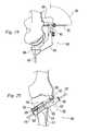
- FIGS. 19-22depict a modification of the guide 300 of FIG. 16 .
- the modified guide 500includes a swivel arm 502 which provides an alternative means of adjusting the vertex drill 350 angle and the sawing plane for the osteotomy 18 .
- the guideincludes medial and lateral arms 504 , 506 .
- the medial arm 504includes a shaft 512 mounted in sliding relationship to the lateral arm 506 .
- a locking knob 514may be loosened to permit sliding adjustment of the spacing of the medial and lateral arms 504 , 506 and tightened to lock them relative to one another.
- the medial and lateral arms 504 , 506include holes 516 for receiving pins 518 to attach the guide 500 to the bone.
- the swivel arm 502is mounted on the guide 500 with two degrees of freedom.
- the swivel arm 502includes a shaft 520 having a shaft axis 522 .
- the shaft 520is mounted on the lateral arm 506 for rotation of the swivel arm 502 about the shaft axis 522 . This rotation adjusts a first angle 524 affecting the direction of the vertex drill similar to the concept of inverting/everting the guide using slidable and swiveling prongs as described relative to FIG. 18 .
- the shaft 520is also mounted for rotation, or hinging, in and out of the plane parallel to the view of FIG.
- a locking screw 527is tightened to lock the swivel arm 502 in place.
- the guide 500includes a drill guide for guiding the drill 350 to form the hole defining the vertex 20 of the osteotomy 18 .
- the drill guideis formed as an integral part of the swivel arm 502 and includes a bore 528 through the swivel arm to receive the drill 350 .
- the guide 500also includes a saw guide 530 having a slot 532 for receiving the saw blade 302 and guiding it at the desired osteotomy location.
- the saw guideis a modular member mounted on the swivel arm and locked in place by a locking screw 534 .
- FIGS. 23 and 24depict a modification of the guide 300 of FIG. 16 .
- the lateral arm 602includes an elongated rail 604 extending medially.
- a medial arm 608is mounted for sliding on the rail 604 .
- a screw 610threads through the medial arm 608 and is mounted to the lateral arm 602 so that it can rotate but not translate. Rotation of the screw 610 causes the medial arm 608 to translate along the rail 604 toward or away from the lateral arm 602 such that a clamping force may be applied between the two arms 602 , 608 by rotating the screw 610 with a manual or powered driver.
- the arms 602 , 608include inwardly directed fixation spikes 605 that grip the bone.
- the medial arm 608may include a plurality of modular attachments, which may include a clamping arm 612 , a cutting/sawing guide 613 like the saw guide 308 of FIG. 16 , a dilator/osteotomy sizer, a temporary implant, drill guides, and an inserter for the implant 614 .
- the implant inserter 614is shown in FIG. 24 attached to the implant 250 of FIGS. 13 and 14 . Turning the screw 610 will cause the inserter 614 to drive the implant 250 into the osteotomy.
- a dilator/osteotomy sizermay be shaped like the implant 250 and driven into and then retracted from the osteotomy as in FIG. 24 to open the osteotomy before insertion of the implant 250 if desired.
- a drill guidemay be attached to the medial arm to guide a drill in forming holes in the bone aligned with the holes 128 of the implant 110 of FIGS. 2-5 , the holes 204 of the implant 200 of FIGS. 10-12 , the holes 252 or 272 of the implant 250 of FIGS. 13 and 14 , or the holes 284 of the implant 280 of FIG. 15 .
- the holesmay be formed from the lateral side by a drill guided by drill guide holes 616 formed in the lateral arm 602 .
- FIG. 25depicts a modification to the guide 600 of FIGS. 22 and 23 .
- the modified guide 650includes an anterior bore 652 through the rail 604 to receive an anterior fixation screw 654 to fix the angle of the guide 650 in the sagittal plane.
- the guide 650further includes a lateral bore 656 through the lateral arm 602 to receive a lateral fixation screw 658 to fix the angle of the guide 650 in the coronal plane.
- FIG. 26depicts a dilator 700 that may be used to dilate the osteotomy prior to inserting the wedge implant 110 .
- the dilator 700may be omitted and the wedge implant 110 may be inserted so that it dilates the osteotomy upon insertion.
- the dilatorincludes a head 702 having the same basic wedge shape as the wedge implant 110 .
- a handle 704is attached to the head 702 to facilitate insertion of the head 702 into the osteotomy 18 .
- the head 702may be inserted by manual pressure on the handle 704 or by impacting the handle 704 .
- a plurality of different sizes of dilators 700may be inserted sequentially to progressively open the osteotomy 18 or a single dilator 700 may be inserted to fully open the osteotomy 18 in one step.
- FIGS. 27-29depict an implant inserter 720 for use with the implant 110 of FIGS. 2-5 .
- the inserter 720includes a shaft 722 having a proximal end 724 and a distal end 726 .
- the proximal end 724is mounted to a handle 728 .
- the distal end 726includes opposing notches 725 (one shown) for engaging the lugs 140 of the implant 110 .
- the lugs 140extend into the notches to constrain the orientation of the wedge implant 110 relative to the inserter 720 along the insertion axis 139 ( FIG. 3 ).
- the lugs 140bottom against a shoulder 727 at the proximal end of the notches 725 to permit an axial insertion force to be imparted from the inserter 720 to the wedge implant 110 along the insertion axis 139 .
- An axial bore 730extends through the handle 728 and through the shaft 722 from the proximal end 724 to the distal end 726 .
- the notches 725are sized so that the distal end of the driver shaft 722 seats adjacent to the portal 138 in the implant 110 with the axial bore 730 directed into the portal 138 .
- a side loading port 732communicates from the outside of the shaft 722 to the axial bore 730 to permit material to be inserted through the port 732 and into the axial bore 730 .
- a plunger 734includes a solid shaft 736 and a knob 738 mounted on the proximal end 740 of the shaft 736 .
- the distal end 742 of the shaft 736is sized for sliding engagement with the axial bore 730 such that the plunger 734 and axial bore 730 form a syringe-like arrangement.
- the distal end 742 of the plunger shaft 736extends distally past the side loading port 732 and closes the port 732 .
- the distal end 742 of the plunger shaft 736extends to the distal end 726 of the inserter shaft 722 .
- the plunger 734may be retracted so that the distal end 742 of the plunger shaft 736 is moved proximal to the port 732 to open the port 732 . Material may then be inserted through the port 732 into the axial bore 730 . Pressing the knob 738 to slide the plunger 734 distally will expel the material from the distal end 726 of the inserter shaft 722 and into the portal 138 of the wedge implant 110 .
- a drill sleeve 750may be provided for guiding a drill to form holes in the cortical bone aligned with the counterbored through holes 128 of the wedge implant 110 .
- the drill sleeve 750includes a drill tube 752 sized to receive the drill and a handle 754 mounted to the drill tube 752 to facilitate positioning the drill sleeve 750 .
- the distal end 756 of the drill tube 752seats in the counterbored holes 128 to guide the drill.
- An optional drill sleeve guide 760may be provided to constrain the direction of the drill sleeve 750 .
- the drill sleeve guide 760includes a body 762 having a slot 764 for engaging the inserter shaft 722 .
- the slot 764may include inwardly directed lugs or pins (not shown) to engage the notches 725 in the inserter shaft 722 . Each lug bottoms against the shoulder 727 at the proximal end of the notches 725 .
- the wedge implant 110is then assembled onto the inserter 720 and bottoms on the drill sleeve guide 760 .
- the drill sleeve guide 760may be removably mountable on the shaft 722 or it may be permanently mounted.
- Elongated tabs 766extend superiorly and inferiorly away from the body 762 .
- the tabs 766include elongated through holes 768 whose long axes are in the superior-inferior direction.
- the wedge implant 110is mounted on the inserter 720 and the drill sleeve 750 is passed through the drill sleeve guide 760 to engage the counterbored through holes 128 in the wedge implant 110 .
- FIGS. 28-29show the alignment of the drill sleeve 750 , relative to the drill sleeve guide 760 and implant holes 128 .
- FIG. 29depicts the case where the fixation plate 126 is not bent. With the drill tube 752 abutting the top 770 of the elongated hole 768 , the drill tube 752 will direct a drill normal to the plate 126 so that a fixation screw can be seated normal to the plate 126 . The gap 772 between the bottom of the elongated hole 768 and the drill tube 752 would permit the drill tube 752 to be angled upwardly to direct the drill at an angle away from the wedge implant 110 and osteotomy 18 .
- FIG. 28depicts the case where the fixation plate 126 is bent outwardly to accommodate an outwardly sloping cortical bone.
- the gap 772 between the bottom of the elongated hole 768 and the drill tube 752permits the drill tube 752 to be angled upwardly to direct the drill at an angle away from the wedge implant 110 and osteotomy 18 to form a hole normal to the plate 126 so that a fixation screw can be seated normal to the plate 126 .
- FIGS. 30-36depict a minimally invasive surgical technique using the implants and instruments of the present invention to perform a medial opening wedge high tibial osteotomy.
- the surgical approachis through the anterior-medial tibial cortex to avoid the medial collateral ligament.
- FIG. 30shows a knee joint with anatomical landmarks marked on the skin to aid the surgeon in placing the guide 300 on the tibia. The landmarks are palpated and the patella 800 is outlined as is the patellar tendon 802 .
- a lineis drawn at the level of the medial tibial plateau 804 .
- a lineis drawn corresponding to the anterior-medial edge 806 of the tibia and another line is drawn corresponding to the posterior medial edge 808 of the tibia.
- one of the lateral prongs of the guide 300is placed through a stab incision to abut the lateral tibial cortex approximately 1.5 cm distal to the lateral tibial plateau. After the guide is angled 30 degrees, this will result in the vertex 20 of the osteotomy 18 being approximately 1.5 cm below the plateau.
- the corresponding medial prongis placed through a stab incision to abut the medial tibial cortex with the saw blade slot 310 angled approximately 30 degrees to the tibial plateau 804 .
- the anglecan be approximated by visualizing the medial arm shaft 312 and lateral arm body 316 at a 30 degree angle.
- alignment rod 370FIG.
- a drill 350may be positioned in the vertex drill guide 348 and used to visualize the angle of the drill relative to the posterior slope of the tibia in the sagittal plane. In the illustrative technique, the guide angle is set to guide the drill 350 parallel to the posterior slope.
- the drill 350is advanced to form an anterior-posterior hole that will define the vertex of the osteotomy and to pin the guide 300 to the bone at the desired sawing angle.
- the drilled holeacts to relieve the stresses at the vertex of the osteotomy.
- the index marks 358 on the drill 350can be referenced and compared to the prong 342 positions to determine the approximate posterior location of the drill tip 362 .
- the drill 350is left in place to shield the saw blade 302 from over penetrating beyond the desired vertex 20 of the osteotomy 18 .
- the saw blade 302is advanced through the slot 310 in the saw guide 308 and swept anteriorly and posteriorly to form the osteotomy 18 .
- the blade 302is advanced up to the drill 350 and withdrawn.
- the blade 302may be used to create a cut of partial depth and the osteotomy 18 may be complete by impacting an osteotome along the cut up to the drill 350 .
- the drill 350 and guide 300are now removed from the bone.
- a dilator 700may optionally be inserted to open the osteotomy.
- the dilatormay also be used to determine the appropriate implant size. Dilators with different thicknesses and different alpha and beta angles 120 , 135 may be inserted until the desired correction is obtained.
- the appropriate implant 110is attached to the inserter 720 and driven into the osteotomy 18 .
- the fixation plates 126may bend upon insertion to conform to the anterior-medial cortex 812 if necessary.
- the fixation plates 126may be pre-bent prior to insertion if necessary.
- the drill sleeve 750 and drill sleeve guide 760may be used to drill through the fixation plates 126 and into the anterior-medial tibial cortex to prepare screw holes. Bone screws 130 are driven to secure the wedge implant 110 as shown in FIG. 35 .
- the inserter 720may be used to inject bone growth promoting substances into the osteotomy 18 between the distal end of the wedge implant 110 and the vertex 20 of the osteotomy by using the plunger 734 to expel the material through the portal 138 in the distal end of the wedge implant 110 .
- the inserter 720is withdrawn and the central opening 136 and proximal gap 134 are manually packed.
- the osteotomy 18may be manually packed prior to and after insertion of the wedge implant 110 and the use of the plunger 734 omitted.
- the osteotomy systemmay be used to form an osteotomy in a variety of locations for a variety of purposes. Two illustrative locations are in the upper tibia to perform an opening high tibial osteotomy and in the distal femur to perform an opening distal femoral osteotomy.
- the systemcan be adapted to perform an osteotomy on various aspects of a bone including medial, lateral, and other aspects. Additional variation and modifications to the illustrative osteotomy system and its use will be apparent to those of ordinary skill in the art, and the following claims are intended to cover all such modifications and equivalents.
Landscapes
- Health & Medical Sciences (AREA)
- Surgery (AREA)
- Life Sciences & Earth Sciences (AREA)
- Orthopedic Medicine & Surgery (AREA)
- Biomedical Technology (AREA)
- Public Health (AREA)
- Veterinary Medicine (AREA)
- Engineering & Computer Science (AREA)
- Nuclear Medicine, Radiotherapy & Molecular Imaging (AREA)
- Heart & Thoracic Surgery (AREA)
- Medical Informatics (AREA)
- Molecular Biology (AREA)
- Animal Behavior & Ethology (AREA)
- General Health & Medical Sciences (AREA)
- Dentistry (AREA)
- Oral & Maxillofacial Surgery (AREA)
- Neurology (AREA)
- Surgical Instruments (AREA)
- Prostheses (AREA)
Abstract
Description
Claims (33)
Priority Applications (1)
| Application Number | Priority Date | Filing Date | Title |
|---|---|---|---|
| US10/958,036US8388690B2 (en) | 2003-10-03 | 2004-10-04 | Osteotomy system |
Applications Claiming Priority (2)
| Application Number | Priority Date | Filing Date | Title |
|---|---|---|---|
| US50877903P | 2003-10-03 | 2003-10-03 | |
| US10/958,036US8388690B2 (en) | 2003-10-03 | 2004-10-04 | Osteotomy system |
Publications (2)
| Publication Number | Publication Date |
|---|---|
| US20050075641A1 US20050075641A1 (en) | 2005-04-07 |
| US8388690B2true US8388690B2 (en) | 2013-03-05 |
Family
ID=34396520
Family Applications (1)
| Application Number | Title | Priority Date | Filing Date |
|---|---|---|---|
| US10/958,036Active2029-01-12US8388690B2 (en) | 2003-10-03 | 2004-10-04 | Osteotomy system |
Country Status (1)
| Country | Link |
|---|---|
| US (1) | US8388690B2 (en) |
Cited By (79)
| Publication number | Priority date | Publication date | Assignee | Title |
|---|---|---|---|---|
| US20130030540A1 (en)* | 2011-07-26 | 2013-01-31 | Rita Leibinger GmbH & Co., KG | Tibia implant for tightening the patella tendons |
| US20140135775A1 (en)* | 2010-02-26 | 2014-05-15 | Biomet Sports Medicine, Llc | Patient-Specific Osteotomy Devices And Methods |
| EP2767247A1 (en) | 2011-07-26 | 2014-08-20 | Rita Leibinger GmbH & Co. KG | Tibia implant for tightening of the patella ligaments |
| US8979936B2 (en) | 2006-06-09 | 2015-03-17 | Biomet Manufacturing, Llc | Patient-modified implant |
| US9005297B2 (en) | 2006-02-27 | 2015-04-14 | Biomet Manufacturing, Llc | Patient-specific elbow guides and associated methods |
| US9060788B2 (en) | 2012-12-11 | 2015-06-23 | Biomet Manufacturing, Llc | Patient-specific acetabular guide for anterior approach |
| US9066734B2 (en) | 2011-08-31 | 2015-06-30 | Biomet Manufacturing, Llc | Patient-specific sacroiliac guides and associated methods |
| US9084618B2 (en) | 2011-06-13 | 2015-07-21 | Biomet Manufacturing, Llc | Drill guides for confirming alignment of patient-specific alignment guides |
| US9113971B2 (en) | 2006-02-27 | 2015-08-25 | Biomet Manufacturing, Llc | Femoral acetabular impingement guide |
| US9173661B2 (en) | 2006-02-27 | 2015-11-03 | Biomet Manufacturing, Llc | Patient specific alignment guide with cutting surface and laser indicator |
| US9173666B2 (en) | 2011-07-01 | 2015-11-03 | Biomet Manufacturing, Llc | Patient-specific-bone-cutting guidance instruments and methods |
| US9204977B2 (en) | 2012-12-11 | 2015-12-08 | Biomet Manufacturing, Llc | Patient-specific acetabular guide for anterior approach |
| US9237950B2 (en) | 2012-02-02 | 2016-01-19 | Biomet Manufacturing, Llc | Implant with patient-specific porous structure |
| US9241745B2 (en) | 2011-03-07 | 2016-01-26 | Biomet Manufacturing, Llc | Patient-specific femoral version guide |
| US9271744B2 (en) | 2010-09-29 | 2016-03-01 | Biomet Manufacturing, Llc | Patient-specific guide for partial acetabular socket replacement |
| US9289253B2 (en) | 2006-02-27 | 2016-03-22 | Biomet Manufacturing, Llc | Patient-specific shoulder guide |
| US9295497B2 (en) | 2011-08-31 | 2016-03-29 | Biomet Manufacturing, Llc | Patient-specific sacroiliac and pedicle guides |
| US9301812B2 (en) | 2011-10-27 | 2016-04-05 | Biomet Manufacturing, Llc | Methods for patient-specific shoulder arthroplasty |
| US9339278B2 (en) | 2006-02-27 | 2016-05-17 | Biomet Manufacturing, Llc | Patient-specific acetabular guides and associated instruments |
| US9345548B2 (en) | 2006-02-27 | 2016-05-24 | Biomet Manufacturing, Llc | Patient-specific pre-operative planning |
| US9351743B2 (en) | 2011-10-27 | 2016-05-31 | Biomet Manufacturing, Llc | Patient-specific glenoid guides |
| US9386993B2 (en) | 2011-09-29 | 2016-07-12 | Biomet Manufacturing, Llc | Patient-specific femoroacetabular impingement instruments and methods |
| US9393028B2 (en) | 2009-08-13 | 2016-07-19 | Biomet Manufacturing, Llc | Device for the resection of bones, method for producing such a device, endoprosthesis suited for this purpose and method for producing such an endoprosthesis |
| US9408616B2 (en) | 2014-05-12 | 2016-08-09 | Biomet Manufacturing, Llc | Humeral cut guide |
| US9427320B2 (en) | 2011-08-04 | 2016-08-30 | Biomet Manufacturing, Llc | Patient-specific pelvic implants for acetabular reconstruction |
| US9445907B2 (en) | 2011-03-07 | 2016-09-20 | Biomet Manufacturing, Llc | Patient-specific tools and implants |
| US9451973B2 (en) | 2011-10-27 | 2016-09-27 | Biomet Manufacturing, Llc | Patient specific glenoid guide |
| US9474539B2 (en) | 2011-04-29 | 2016-10-25 | Biomet Manufacturing, Llc | Patient-specific convertible guides |
| US9480580B2 (en) | 2006-02-27 | 2016-11-01 | Biomet Manufacturing, Llc | Patient-specific acetabular alignment guides |
| US9480490B2 (en) | 2006-02-27 | 2016-11-01 | Biomet Manufacturing, Llc | Patient-specific guides |
| US9498233B2 (en) | 2013-03-13 | 2016-11-22 | Biomet Manufacturing, Llc. | Universal acetabular guide and associated hardware |
| US9517145B2 (en) | 2013-03-15 | 2016-12-13 | Biomet Manufacturing, Llc | Guide alignment system and method |
| US9522010B2 (en) | 2006-02-27 | 2016-12-20 | Biomet Manufacturing, Llc | Patient-specific orthopedic instruments |
| US9554910B2 (en) | 2011-10-27 | 2017-01-31 | Biomet Manufacturing, Llc | Patient-specific glenoid guide and implants |
| US9561040B2 (en) | 2014-06-03 | 2017-02-07 | Biomet Manufacturing, Llc | Patient-specific glenoid depth control |
| US9572590B2 (en) | 2006-10-03 | 2017-02-21 | Biomet Uk Limited | Surgical instrument |
| US9579107B2 (en) | 2013-03-12 | 2017-02-28 | Biomet Manufacturing, Llc | Multi-point fit for patient specific guide |
| US9662216B2 (en) | 2006-02-27 | 2017-05-30 | Biomet Manufacturing, Llc | Patient-specific hip joint devices |
| US9662127B2 (en) | 2006-02-27 | 2017-05-30 | Biomet Manufacturing, Llc | Patient-specific acetabular guides and associated instruments |
| US9675400B2 (en) | 2011-04-19 | 2017-06-13 | Biomet Manufacturing, Llc | Patient-specific fracture fixation instrumentation and method |
| US9717510B2 (en) | 2011-04-15 | 2017-08-01 | Biomet Manufacturing, Llc | Patient-specific numerically controlled instrument |
| US9743940B2 (en) | 2011-04-29 | 2017-08-29 | Biomet Manufacturing, Llc | Patient-specific partial knee guides and other instruments |
| US9757238B2 (en) | 2011-06-06 | 2017-09-12 | Biomet Manufacturing, Llc | Pre-operative planning and manufacturing method for orthopedic procedure |
| WO2017164861A1 (en)* | 2016-03-23 | 2017-09-28 | Wright Medical Technology, Inc | Wedge plates and methods of use |
| US9795399B2 (en) | 2006-06-09 | 2017-10-24 | Biomet Manufacturing, Llc | Patient-specific knee alignment guide and associated method |
| US9820868B2 (en) | 2015-03-30 | 2017-11-21 | Biomet Manufacturing, Llc | Method and apparatus for a pin apparatus |
| US9826994B2 (en) | 2014-09-29 | 2017-11-28 | Biomet Manufacturing, Llc | Adjustable glenoid pin insertion guide |
| US9826981B2 (en) | 2013-03-13 | 2017-11-28 | Biomet Manufacturing, Llc | Tangential fit of patient-specific guides |
| US9833245B2 (en) | 2014-09-29 | 2017-12-05 | Biomet Sports Medicine, Llc | Tibial tubercule osteotomy |
| US9839438B2 (en) | 2013-03-11 | 2017-12-12 | Biomet Manufacturing, Llc | Patient-specific glenoid guide with a reusable guide holder |
| US9839436B2 (en) | 2014-06-03 | 2017-12-12 | Biomet Manufacturing, Llc | Patient-specific glenoid depth control |
| US9907659B2 (en) | 2007-04-17 | 2018-03-06 | Biomet Manufacturing, Llc | Method and apparatus for manufacturing an implant |
| US9918740B2 (en) | 2006-02-27 | 2018-03-20 | Biomet Manufacturing, Llc | Backup surgical instrument system and method |
| US9968376B2 (en) | 2010-11-29 | 2018-05-15 | Biomet Manufacturing, Llc | Patient-specific orthopedic instruments |
| US10159498B2 (en) | 2008-04-16 | 2018-12-25 | Biomet Manufacturing, Llc | Method and apparatus for manufacturing an implant |
| US10226262B2 (en) | 2015-06-25 | 2019-03-12 | Biomet Manufacturing, Llc | Patient-specific humeral guide designs |
| US10282488B2 (en) | 2014-04-25 | 2019-05-07 | Biomet Manufacturing, Llc | HTO guide with optional guided ACL/PCL tunnels |
| US10278711B2 (en) | 2006-02-27 | 2019-05-07 | Biomet Manufacturing, Llc | Patient-specific femoral guide |
| US10492798B2 (en) | 2011-07-01 | 2019-12-03 | Biomet Manufacturing, Llc | Backup kit for a patient-specific arthroplasty kit assembly |
| US10568647B2 (en) | 2015-06-25 | 2020-02-25 | Biomet Manufacturing, Llc | Patient-specific humeral guide designs |
| US10603179B2 (en) | 2006-02-27 | 2020-03-31 | Biomet Manufacturing, Llc | Patient-specific augments |
| US10722310B2 (en) | 2017-03-13 | 2020-07-28 | Zimmer Biomet CMF and Thoracic, LLC | Virtual surgery planning system and method |
| US10842632B2 (en) | 2018-07-13 | 2020-11-24 | Uwe R. Pontius | Method and apparatus for orthopedic implant |
| US11000298B1 (en) | 2020-01-16 | 2021-05-11 | Thomas Graziano | Minimally invasive bunionectomy procedure using chevron osteotomy guide |
| US20210330385A1 (en)* | 2018-08-24 | 2021-10-28 | Laboratoires Bodycad Inc | Surgical kit for knee osteotomies and corresponding preoperative planning method |
| US11179165B2 (en) | 2013-10-21 | 2021-11-23 | Biomet Manufacturing, Llc | Ligament guide registration |
| US11224448B2 (en)* | 2019-06-27 | 2022-01-18 | Erroll J. Bailey | Method and system for minimally invasive bone extra-articular reconstruction |
| US11229443B2 (en) | 2018-12-03 | 2022-01-25 | Wright Medical Technology, Inc. | Minimally invasive guides and cutting instruments |
| USD943100S1 (en) | 2020-02-18 | 2022-02-08 | Laboratoires Bodycad Inc. | Osteotomy plate |
| US11266449B2 (en) | 2017-12-19 | 2022-03-08 | Orthopediatrics Corp | Osteotomy device and methods |
| USD948719S1 (en) | 2019-10-21 | 2022-04-12 | Laboratoires Bodycad Inc. | Posterior stabilizer for an osteotomy plate |
| US11419618B2 (en) | 2011-10-27 | 2022-08-23 | Biomet Manufacturing, Llc | Patient-specific glenoid guides |
| US11517333B2 (en) | 2018-08-24 | 2022-12-06 | Laboratoires Bodycad Inc. | Predrilling guide for knee osteotomy fixation plate |
| US11571308B1 (en) | 2021-11-22 | 2023-02-07 | Uwe R. Pontius | Orthopedic implant having mechanical interlocking subunits and related methods |
| US11589876B2 (en) | 2018-08-24 | 2023-02-28 | Laboratoires Bodycad Inc. | Surgical guide assembly for performing a knee osteotomy procedure |
| US11622801B2 (en) | 2018-08-24 | 2023-04-11 | Laboratoires Bodycad Inc. | Patient-specific fixation plate with wedge member for knee osteotomies |
| US11701150B2 (en) | 2018-08-24 | 2023-07-18 | Laboratoires Bodycad Inc. | Patient-specific fixation plate with spacing elements |
| US11857206B2 (en) | 2018-08-24 | 2024-01-02 | Laboratoires Bodycad Inc. | Patient-specific surgical tools |
| US12226505B2 (en) | 2018-10-25 | 2025-02-18 | The Procter & Gamble Company | Compositions having enhanced deposition of surfactant-soluble anti-dandruff agents |
Families Citing this family (166)
| Publication number | Priority date | Publication date | Assignee | Title |
|---|---|---|---|---|
| US7497874B1 (en) | 2001-02-23 | 2009-03-03 | Biomet Manufacturing Corp. | Knee joint prosthesis |
| US20020120340A1 (en)* | 2001-02-23 | 2002-08-29 | Metzger Robert G. | Knee joint prosthesis |
| US7112204B2 (en)* | 2003-02-06 | 2006-09-26 | Medicinelodge, Inc. | Tibial tubercle osteotomy for total knee arthroplasty and instruments and implants therefor |
| US8083746B2 (en)* | 2004-05-07 | 2011-12-27 | Arthrex, Inc. | Open wedge osteotomy system and surgical method |
| US8388667B2 (en) | 2004-08-09 | 2013-03-05 | Si-Bone, Inc. | Systems and methods for the fixation or fusion of bone using compressive implants |
| US9949843B2 (en) | 2004-08-09 | 2018-04-24 | Si-Bone Inc. | Apparatus, systems, and methods for the fixation or fusion of bone |
| US8470004B2 (en) | 2004-08-09 | 2013-06-25 | Si-Bone Inc. | Apparatus, systems, and methods for stabilizing a spondylolisthesis |
| US8414648B2 (en) | 2004-08-09 | 2013-04-09 | Si-Bone Inc. | Apparatus, systems, and methods for achieving trans-iliac lumbar fusion |
| US20180228621A1 (en) | 2004-08-09 | 2018-08-16 | Mark A. Reiley | Apparatus, systems, and methods for the fixation or fusion of bone |
| US9662158B2 (en)* | 2004-08-09 | 2017-05-30 | Si-Bone Inc. | Systems and methods for the fixation or fusion of bone at or near a sacroiliac joint |
| US20060036251A1 (en) | 2004-08-09 | 2006-02-16 | Reiley Mark A | Systems and methods for the fixation or fusion of bone |
| US8425570B2 (en) | 2004-08-09 | 2013-04-23 | Si-Bone Inc. | Apparatus, systems, and methods for achieving anterior lumbar interbody fusion |
| US20070156241A1 (en) | 2004-08-09 | 2007-07-05 | Reiley Mark A | Systems and methods for the fixation or fusion of bone |
| US7935119B2 (en) | 2005-01-31 | 2011-05-03 | Ibalance Medical, Inc. | Method for performing an open wedge, high tibial osteotomy |
| WO2008039269A2 (en)* | 2006-08-02 | 2008-04-03 | Ibalance Medical, Inc. | Method and apparatus for performing an open wedge, high tibial osteotomy |
| US7967823B2 (en)* | 2005-01-31 | 2011-06-28 | Arthrex, Inc. | Method and apparatus for performing an open wedge, high tibial osteotomy |
| US8540777B2 (en)* | 2005-01-31 | 2013-09-24 | Arthrex, Inc. | Method and apparatus for performing an open wedge, high tibial osteotomy |
| WO2008016687A2 (en)* | 2006-08-02 | 2008-02-07 | Ibalance Medical, Inc. | Method and apparatus for performing a high tibial, dome osteotomy |
| US8906026B2 (en) | 2005-01-31 | 2014-12-09 | Arthrex, Inc. | Method and apparatus for performing an open wedge, high tibial osteotomy |
| US8496662B2 (en)* | 2005-01-31 | 2013-07-30 | Arthrex, Inc. | Method and apparatus for forming a wedge-like opening in a bone for an open wedge osteotomy |
| US8771279B2 (en) | 2005-01-31 | 2014-07-08 | Arthrex, Inc. | Method and apparatus for performing an osteotomy in bone |
| CA2597228C (en)* | 2005-02-09 | 2014-07-22 | Ibalance Medical, Inc. | Multi-part implant for open wedge knee osteotomies |
| US7931680B2 (en)* | 2005-03-31 | 2011-04-26 | Depuy Products, Inc. | Plate for lengthening the lateral column of the foot |
| CA2603400C (en)* | 2005-04-01 | 2015-11-24 | Ibalance Medical, Inc. | Method and apparatus for performing an open wedge, high tibial osteotomy |
| WO2007064950A2 (en) | 2005-12-01 | 2007-06-07 | Ibalance Medical, Inc. | Open wedge, high bitial osteotomy method and apparatus |
| WO2007076075A2 (en)* | 2005-12-22 | 2007-07-05 | Ibalance Medical, Inc. | Method and apparatus for performing an open wedge, high tibial osteotomy |
| US8506597B2 (en)* | 2011-10-25 | 2013-08-13 | Biomet Sports Medicine, Llc | Method and apparatus for interosseous membrane reconstruction |
| US8241293B2 (en)* | 2006-02-27 | 2012-08-14 | Biomet Manufacturing Corp. | Patient specific high tibia osteotomy |
| US8473305B2 (en) | 2007-04-17 | 2013-06-25 | Biomet Manufacturing Corp. | Method and apparatus for manufacturing an implant |
| US8092465B2 (en) | 2006-06-09 | 2012-01-10 | Biomet Manufacturing Corp. | Patient specific knee alignment guide and associated method |
| US8298237B2 (en) | 2006-06-09 | 2012-10-30 | Biomet Manufacturing Corp. | Patient-specific alignment guide for multiple incisions |
| US8282646B2 (en) | 2006-02-27 | 2012-10-09 | Biomet Manufacturing Corp. | Patient specific knee alignment guide and associated method |
| US8858561B2 (en) | 2006-06-09 | 2014-10-14 | Blomet Manufacturing, LLC | Patient-specific alignment guide |
| US8070752B2 (en) | 2006-02-27 | 2011-12-06 | Biomet Manufacturing Corp. | Patient specific alignment guide and inter-operative adjustment |
| US8133234B2 (en) | 2006-02-27 | 2012-03-13 | Biomet Manufacturing Corp. | Patient specific acetabular guide and method |
| US8864769B2 (en) | 2006-02-27 | 2014-10-21 | Biomet Manufacturing, Llc | Alignment guides with patient-specific anchoring elements |
| US8241292B2 (en)* | 2006-06-30 | 2012-08-14 | Howmedica Osteonics Corp. | High tibial osteotomy system |
| WO2008019049A2 (en)* | 2006-08-03 | 2008-02-14 | Ibalance Medical Inc. | Method and apparatus for performing an open wedge, high tibial osteotomy |
| WO2008019114A2 (en)* | 2006-08-03 | 2008-02-14 | Ibalance Medical, Inc. | Method and apparatus for performing an open wedge, high tibial osteotomy |
| US8100975B2 (en)* | 2006-08-11 | 2012-01-24 | Warsaw Orthopedic, Inc. | Intervertebral implants with attachable flanges and methods of use |
| WO2008039508A2 (en) | 2006-09-27 | 2008-04-03 | Ibalance Medical, Inc. | Method and apparatus for performing an open wedge, high tibial osteotomy |
| US8409209B2 (en)* | 2006-11-22 | 2013-04-02 | Arthrex, Inc. | Method and apparatus for performing an open wedge, high tibial osteotomy |
| WO2008065450A1 (en)* | 2006-11-29 | 2008-06-05 | Surgicraft Limited | Orthopaedic implants and prostheses |
| US20080208197A1 (en)* | 2006-11-30 | 2008-08-28 | Kelly Ammann | Method and apparatus for performing an open wedge, high tibial osteotomy |
| WO2008070027A2 (en) | 2006-12-01 | 2008-06-12 | Ibalance Medical, Inc. | Method and apparatus for performing an open wedge, low femoral osteotomy |
| US8163028B2 (en) | 2007-01-10 | 2012-04-24 | Biomet Manufacturing Corp. | Knee joint prosthesis system and method for implantation |
| JP5448842B2 (en) | 2007-01-10 | 2014-03-19 | バイオメト マニファクチャリング コーポレイション | Knee joint prosthesis system and implantation method |
| US8562616B2 (en) | 2007-10-10 | 2013-10-22 | Biomet Manufacturing, Llc | Knee joint prosthesis system and method for implantation |
| US8187280B2 (en) | 2007-10-10 | 2012-05-29 | Biomet Manufacturing Corp. | Knee joint prosthesis system and method for implantation |
| US8328873B2 (en) | 2007-01-10 | 2012-12-11 | Biomet Manufacturing Corp. | Knee joint prosthesis system and method for implantation |
| US20080195099A1 (en)* | 2007-02-13 | 2008-08-14 | The Brigham And Women's Hospital, Inc. | Osteotomy system |
| US8926618B2 (en) | 2007-04-19 | 2015-01-06 | Howmedica Osteonics Corp. | Cutting guide with internal distraction |
| WO2008140748A1 (en)* | 2007-05-09 | 2008-11-20 | Ibalance Medical, Inc. | Method and apparatus for reconstructing a ligament and/or repairing cartilage, and for performing an open wedge, high tibial osteotomy |
| US8265949B2 (en) | 2007-09-27 | 2012-09-11 | Depuy Products, Inc. | Customized patient surgical plan |
| US8979855B2 (en) | 2007-09-30 | 2015-03-17 | DePuy Synthes Products, Inc. | Customized patient-specific bone cutting blocks |
| EP2194889B1 (en) | 2007-09-30 | 2015-09-23 | DePuy Products, Inc. | Customized patient-specific orthopaedic surgical instrumentation |
| WO2011106400A1 (en) | 2010-02-25 | 2011-09-01 | Depuy Products, Inc. | Customized patient-specific tibial cutting blocks |
| US9173662B2 (en) | 2007-09-30 | 2015-11-03 | DePuy Synthes Products, Inc. | Customized patient-specific tibial cutting blocks |
| WO2011106430A1 (en) | 2010-02-25 | 2011-09-01 | Depuy Products, Inc | Customized patient-specific bone cutting blocks |
| US8357111B2 (en) | 2007-09-30 | 2013-01-22 | Depuy Products, Inc. | Method and system for designing patient-specific orthopaedic surgical instruments |
| US20090157190A1 (en)* | 2007-12-13 | 2009-06-18 | Howmedica Inc. | Osteotomy spacer |
| US20090177203A1 (en)* | 2008-01-04 | 2009-07-09 | Inbone Technologies, Inc. | Devices, systems and methods for re-alignment of bone |
| US8353915B2 (en)* | 2008-06-19 | 2013-01-15 | Arthrex, Inc. | AMZ tibial tuberosity transfer system |
| US8192441B2 (en)* | 2008-10-03 | 2012-06-05 | Howmedica Osteonics Corp. | High tibial osteotomy instrumentation |
| EP2367485B8 (en)* | 2008-10-21 | 2015-05-27 | Arthrex, Inc. | Apparatus for performing an open wedge, high tibial osteotomy |
| US20100168799A1 (en)* | 2008-12-29 | 2010-07-01 | Schumer Evan D | Ulnar osteotomy plate including increased compression |
| US8170641B2 (en) | 2009-02-20 | 2012-05-01 | Biomet Manufacturing Corp. | Method of imaging an extremity of a patient |
| US20110087295A1 (en)* | 2009-10-12 | 2011-04-14 | University Of Utah | Bone fixation systems |
| US8657820B2 (en) | 2009-10-12 | 2014-02-25 | Tornier, Inc. | Bone plate and keel systems |
| US8864768B2 (en) | 2009-11-20 | 2014-10-21 | Zimmer Knee Creations, Inc. | Coordinate mapping system for joint treatment |
| EP2501303B1 (en)* | 2009-11-20 | 2020-02-12 | Zimmer Knee Creations, Inc. | Navigation and positioning instruments for joint repair |
| WO2011063240A1 (en) | 2009-11-20 | 2011-05-26 | Knee Creations, Llc | Implantable devices for subchondral treatment of joint pain |
| JP2013511356A (en) | 2009-11-20 | 2013-04-04 | ニー・クリエイションズ・リミテッド・ライアビリティ・カンパニー | Device for variable angle approach to joints |
| US9259257B2 (en) | 2009-11-20 | 2016-02-16 | Zimmer Knee Creations, Inc. | Instruments for targeting a joint defect |
| US8821504B2 (en) | 2009-11-20 | 2014-09-02 | Zimmer Knee Creations, Inc. | Method for treating joint pain and associated instruments |
| WO2011063260A1 (en) | 2009-11-20 | 2011-05-26 | Knee Creations, Llc | Bone-derived implantable devices for subchondral treatment of joint pain |
| US8951261B2 (en) | 2009-11-20 | 2015-02-10 | Zimmer Knee Creations, Inc. | Subchondral treatment of joint pain |
| JP2013512042A (en)* | 2009-11-27 | 2013-04-11 | シンセス ゲゼルシャフト ミット ベシュレンクテル ハフツング | Planar fixation concept for distal radius fractures |
| KR101073872B1 (en) | 2009-12-14 | 2011-10-14 | 서경석 | Tibial osteotomy with aligning function with lower femoral fracture |
| US8834568B2 (en) | 2010-02-04 | 2014-09-16 | Paul S. Shapiro | Surgical technique using a contoured allograft cartilage as a spacer of the carpo-metacarpal joint of the thumb or tarso-metatarsal joint of the toe |
| US8444699B2 (en)* | 2010-02-18 | 2013-05-21 | Biomet Manufacturing Corp. | Method and apparatus for augmenting bone defects |
| WO2011106407A1 (en) | 2010-02-25 | 2011-09-01 | Depuy Products, Inc. | Method of fabricating customized patient-specific bone cutting blocks |
| US9066727B2 (en) | 2010-03-04 | 2015-06-30 | Materialise Nv | Patient-specific computed tomography guides |
| USD653339S1 (en)* | 2011-04-18 | 2012-01-31 | Ascension Orthopedics, Inc. | Double cannulated osteotome |
| EP2701616A1 (en) | 2011-04-28 | 2014-03-05 | Materialise N.V. | Stopping tool guides and combinations thereof with surgical guides, methods for manufacturing and uses thereof |
| US20130218284A1 (en)* | 2012-02-16 | 2013-08-22 | Mobius Medical LLC | Tibial baseplate assembly for knee joint prosthesis |
| US20140276851A1 (en)* | 2013-03-15 | 2014-09-18 | Bret W. SCHNEIDER | Systems and methods for removing an implant |
| US9044321B2 (en) | 2012-03-09 | 2015-06-02 | Si-Bone Inc. | Integrated implant |
| US10363140B2 (en) | 2012-03-09 | 2019-07-30 | Si-Bone Inc. | Systems, device, and methods for joint fusion |
| EP3818947B1 (en) | 2012-05-04 | 2023-08-30 | SI-Bone, Inc. | Fenestrated implant |
| CA2876834A1 (en)* | 2012-06-14 | 2013-12-19 | DePuy Synthes Products, LLC | Implants/procedures related to tibial tuberosity advancement |
| US20140031829A1 (en)* | 2012-07-30 | 2014-01-30 | Orthosoft, Inc. | Method and system for creating frame of reference for cas with inertial sensors |
| FR2996440A1 (en)* | 2012-10-09 | 2014-04-11 | Neosteo | CUTTING GUIDE FOR OSTEOTOMY |
| US10864081B2 (en)* | 2012-10-19 | 2020-12-15 | Tyber Medical, LLC | Wedge osteotomy device and method of use |
| US8920512B2 (en)* | 2012-12-19 | 2014-12-30 | Biomet Sports Medicine, Llc | Method and apparatus for pre-forming a high tibial osteotomy |
| US10307191B2 (en)* | 2015-08-19 | 2019-06-04 | In2Bones Usa, Llc | Subtalar plate implant |
| WO2014145902A1 (en) | 2013-03-15 | 2014-09-18 | Si-Bone Inc. | Implants for spinal fixation or fusion |
| MY165689A (en)* | 2013-09-12 | 2018-04-20 | Khay Yong Saw Dr | Osteotomy below the tibial tuberosity by multiple drilling |
| US11147688B2 (en) | 2013-10-15 | 2021-10-19 | Si-Bone Inc. | Implant placement |
| US9839448B2 (en) | 2013-10-15 | 2017-12-12 | Si-Bone Inc. | Implant placement |
| TR201809866T4 (en) | 2013-11-03 | 2018-07-23 | Ignite Concepts Gmbh | Osteotomy implant. |
| US20150335367A1 (en)* | 2014-05-20 | 2015-11-26 | Neutin Orthopedics, LLC | Medical grade cotton and evans osteotomy wedges |
| US20160015426A1 (en) | 2014-07-15 | 2016-01-21 | Treace Medical Concepts, Inc. | Bone positioning and cutting system and method |
| US10166033B2 (en) | 2014-09-18 | 2019-01-01 | Si-Bone Inc. | Implants for bone fixation or fusion |
| JP6542362B2 (en) | 2014-09-18 | 2019-07-10 | エスアイ−ボーン・インコーポレイテッドSi−Bone, Inc. | Matrix implant |
| US10383733B2 (en) | 2014-10-22 | 2019-08-20 | Biomet C.V. | Method and apparatus for bone fixation |
| TR201412961A2 (en)* | 2014-11-04 | 2016-05-23 | Melih Gueven | High tibial osteotomy external fixator. |
| US9687250B2 (en) | 2015-01-07 | 2017-06-27 | Treace Medical Concepts, Inc. | Bone cutting guide systems and methods |
| WO2016134154A1 (en) | 2015-02-18 | 2016-08-25 | Treace Medical Concepts, Inc. | Pivotable bone cutting guide useful for bone realignment and compression techniques |
| US10376206B2 (en) | 2015-04-01 | 2019-08-13 | Si-Bone Inc. | Neuromonitoring systems and methods for bone fixation or fusion procedures |
| US10653467B2 (en) | 2015-05-06 | 2020-05-19 | Treace Medical Concepts, Inc. | Intra-osseous plate system and method |
| US9622805B2 (en) | 2015-08-14 | 2017-04-18 | Treace Medical Concepts, Inc. | Bone positioning and preparing guide systems and methods |
| US10849663B2 (en) | 2015-07-14 | 2020-12-01 | Treace Medical Concepts, Inc. | Bone cutting guide systems and methods |
| EP4483824A3 (en) | 2015-07-14 | 2025-03-05 | Treace Medical Concepts, Inc. | Bone positioning guide |
| WO2017031020A1 (en) | 2015-08-14 | 2017-02-23 | Treace Medical Concepts, Inc. | Tarsal-metatarsal joint procedure utilizing fulcrum |
| EP4494582A3 (en) | 2015-08-14 | 2025-04-16 | Treace Medical Concepts, Inc. | Tarsal-metatarsal joint procedure utilizing fulcrum |
| CA2998481C (en) | 2015-09-18 | 2024-05-14 | Treace Medical Concepts, Inc. | Joint spacer systems and methods |
| ITUA20162794A1 (en)* | 2016-04-21 | 2017-10-21 | Ad Maiora Srl | Implant for advancement of the tibial crest. |
| US10512470B1 (en) | 2016-08-26 | 2019-12-24 | Treace Medical Concepts, Inc. | Osteotomy procedure for correcting bone misalignment |
| US10524808B1 (en) | 2016-11-11 | 2020-01-07 | Treace Medical Concepts, Inc. | Devices and techniques for performing an osteotomy procedure on a first metatarsal to correct a bone misalignment |
| US10543028B2 (en)* | 2017-02-06 | 2020-01-28 | Biomet Manufacturing, Llc | Adjustable wedge |
| WO2018151859A1 (en)* | 2017-02-16 | 2018-08-23 | Paragon 28, Inc. | Implants, devices, systems, kits and methods of implanting |
| US10939939B1 (en) | 2017-02-26 | 2021-03-09 | Treace Medical Concepts, Inc. | Fulcrum for tarsal-metatarsal joint procedure |
| EP3453349A1 (en)* | 2017-09-10 | 2019-03-13 | Yechiel Gotfried | Orthopaedic implant |
| CN109481094B (en)* | 2017-09-11 | 2023-06-02 | 耶器尔·戈特弗赖德 | Orthopedic implant |
| US11116519B2 (en) | 2017-09-26 | 2021-09-14 | Si-Bone Inc. | Systems and methods for decorticating the sacroiliac joint |
| CN108210014B (en)* | 2018-02-13 | 2023-12-22 | 苏州爱得科技发展股份有限公司 | Osteotomy guide plate |
| IT201800002734A1 (en)* | 2018-02-16 | 2019-08-16 | Shoulder App S R L | Prosthesis for the glenohumeral joint. |
| ES3011907T3 (en) | 2018-03-28 | 2025-04-08 | Si Bone Inc | Threaded implants for use across bone segments |
| US11051829B2 (en) | 2018-06-26 | 2021-07-06 | DePuy Synthes Products, Inc. | Customized patient-specific orthopaedic surgical instrument |
| WO2020014320A1 (en)* | 2018-07-10 | 2020-01-16 | Paragon 28, Inc. | Guides, instruments, systems and methods of use |
| US11690660B2 (en) | 2018-07-10 | 2023-07-04 | Paragon 28, Inc. | Guides, instruments, systems and methods of use |
| US11596443B2 (en) | 2018-07-11 | 2023-03-07 | Treace Medical Concepts, Inc. | Compressor-distractor for angularly realigning bone portions |
| US11583323B2 (en) | 2018-07-12 | 2023-02-21 | Treace Medical Concepts, Inc. | Multi-diameter bone pin for installing and aligning bone fixation plate while minimizing bone damage |
| US11075495B2 (en)* | 2018-12-06 | 2021-07-27 | Raytheon Company | Connector installation tool |
| US11607250B2 (en) | 2019-02-13 | 2023-03-21 | Treace Medical Concepts, Inc. | Tarsal-metatarsal joint procedure utilizing compressor-distractor and instrument providing sliding surface |
| EP4613244A2 (en) | 2019-02-14 | 2025-09-10 | SI-Bone Inc. | Implants for spinal fixation and or fusion |
| US11369419B2 (en) | 2019-02-14 | 2022-06-28 | Si-Bone Inc. | Implants for spinal fixation and or fusion |
| CA3146564A1 (en) | 2019-08-07 | 2021-02-11 | Jason May | Bi-planar instrument for bone cutting and joint realignment procedure |
| US11889998B1 (en) | 2019-09-12 | 2024-02-06 | Treace Medical Concepts, Inc. | Surgical pin positioning lock |
| EP4027922A4 (en) | 2019-09-13 | 2023-10-04 | MIOS Marketing LLC, DBA RedPoint Medical 3D | Patient-specific surgical methods and instrumentation |
| US11890039B1 (en) | 2019-09-13 | 2024-02-06 | Treace Medical Concepts, Inc. | Multi-diameter K-wire for orthopedic applications |
| US11986251B2 (en) | 2019-09-13 | 2024-05-21 | Treace Medical Concepts, Inc. | Patient-specific osteotomy instrumentation |
| JP7646654B2 (en) | 2019-11-21 | 2025-03-17 | エスアイ-ボーン・インコーポレイテッド | Rod coupling assembly for bone stabilization construct - Patent application |
| AU2020392121B2 (en) | 2019-11-27 | 2025-05-22 | Si-Bone, Inc. | Bone stabilizing implants and methods of placement across SI joints |
| EP4072452A4 (en) | 2019-12-09 | 2023-12-20 | SI-Bone, Inc. | Sacro-iliac joint stabilizing implants and methods of implantation |
| WO2021155269A1 (en) | 2020-01-31 | 2021-08-05 | Treace Medical Concepts, Inc. | Metatarsophalangeal joint preparation and metatarsal realignment for fusion |
| EP4104771A4 (en)* | 2020-02-10 | 2023-11-01 | Ames Medical Prosthetic Solutions, S.A.U. | PROSTHESIS |
| CN111134830B (en)* | 2020-02-25 | 2024-12-20 | 山东大学齐鲁医院(青岛) | Proximal humeral fracture reduction guide |
| CN111467015A (en)* | 2020-05-18 | 2020-07-31 | 武汉大学中南医院 | Hook plate for fibula near-end fracture |
| AU2021275140A1 (en) | 2020-05-19 | 2023-02-02 | Treace Medical Concepts, Inc. | Devices and techniques for treating metatarsus adductus |
| DE102020209981A1 (en)* | 2020-08-06 | 2022-02-10 | Karl Leibinger Medizintechnik Gmbh & Co. Kg | implant system |
| EP4259015A4 (en) | 2020-12-09 | 2024-09-11 | SI-Bone, Inc. | SACROILIAC JOINT STABILIZATION IMPLANTS AND METHODS OF IMPLANTATION |
| US12161371B2 (en) | 2021-01-18 | 2024-12-10 | Treace Medical Concepts, Inc. | Contoured bone plate with locking screw for bone compression, particularly across a tarsometatarsal joint |
| US12310603B2 (en) | 2021-02-18 | 2025-05-27 | Treace Medical Concepts, Inc. | System and technique for metatarsal realignment with reduced incision length |
| AU2022276540A1 (en) | 2021-05-20 | 2023-11-30 | Treace Medical Concepts, Inc. | Cut guide with integrated joint realignment features |
| KR102362366B1 (en)* | 2021-07-29 | 2022-02-14 | (주)메디쎄이 | Apparatus for maintaining spacing of cutout portion of lamina used for patient customized laminoplasty |
| USD1075012S1 (en) | 2022-02-23 | 2025-05-13 | Treace Medical Concepts, Inc. | Metatarsal lateral release instrument |
| USD1079011S1 (en) | 2022-02-23 | 2025-06-10 | Treace Medical Concepts, Inc. | Metatarsal cut guide with parallel cut faces |
| USD1011524S1 (en) | 2022-02-23 | 2024-01-16 | Treace Medical Concepts, Inc. | Compressor-distractor for the foot |
| USD1051382S1 (en) | 2022-02-23 | 2024-11-12 | Treace Medical Concepts, Inc. | Lesser metatarsal cut guide |
| USD1057155S1 (en) | 2022-02-23 | 2025-01-07 | Treace Medical Concepts, Inc. | Lesser metatarsal cut guide with parallel cut faces |
| US20230310047A1 (en)* | 2022-03-31 | 2023-10-05 | Medartis Ag | Bone wedge implant and method |
| USD1068077S1 (en) | 2023-02-08 | 2025-03-25 | Treace Medical Concepts, Inc. | Orthopedic rasp for preparing an intercuneiform joint |
| USD1068078S1 (en) | 2023-02-08 | 2025-03-25 | Treace Medical Concepts, Inc. | Handle for an orthopedic instrument |
| WO2025038769A1 (en) | 2023-08-15 | 2025-02-20 | Si-Bone Inc. | Pelvic stabilization implants, methods of use and manufacture |
Citations (13)
| Publication number | Priority date | Publication date | Assignee | Title |
|---|---|---|---|---|
| US4759351A (en)* | 1986-12-29 | 1988-07-26 | Slocum D Barclay | Osteotomy method for biomechanical femoral neck lengthening and torsion |
| FR2612392A1 (en)* | 1987-03-19 | 1988-09-23 | Audion Michel | Interrupted biodegradable composites of variable strength |
| SU1653762A1 (en)* | 1989-06-16 | 1991-06-07 | Сибирский Физико-Технический Институт Им.В.Д.Кузнецова Пи Томском Государственном Университете Им.В.В.Куйбышева | Endoprosthesis for substituting the bony defects |
| JPH05208029A (en)* | 1992-01-31 | 1993-08-20 | Kyocera Corp | Artificial vertebral body spacer |
| FR2727005A1 (en)* | 1994-11-18 | 1996-05-24 | Euros Sa | Anterior stabiliser for cervical section of spine |
| EP0834295A1 (en)* | 1996-10-03 | 1998-04-08 | Medinov-Amp | Vertebral interbody arthrodesis prosthesis |
| EP0869753B1 (en)* | 1995-12-21 | 2000-07-05 | Colorado | Interbody vertebral implant |
| US6086593A (en)* | 1998-06-30 | 2000-07-11 | Bonutti; Peter M. | Method and apparatus for use in operating on a bone |
| DE20012549U1 (en)* | 2000-07-20 | 2000-10-12 | Aesculap AG & Co. KG, 78532 Tuttlingen | Insertion tool for an intervertebral implant |
| US6203546B1 (en)* | 1999-07-27 | 2001-03-20 | Macmahon Edward B | Method and apparatus for medial tibial osteotomy |
| US6221075B1 (en)* | 1998-03-06 | 2001-04-24 | Bionx Implants Oy | Bioabsorbable, deformable fixation plate |
| US20020107571A1 (en)* | 2001-02-06 | 2002-08-08 | Foley Kevin T. | Spinal bone implant |
| US6544266B1 (en)* | 1999-01-22 | 2003-04-08 | Australian Surgical Design And Manufacture Pty, Ltd. | Method and apparatus for delivering bio-active compounds to specified sites in the body |
- 2004
- 2004-10-04USUS10/958,036patent/US8388690B2/enactiveActive
Patent Citations (13)
| Publication number | Priority date | Publication date | Assignee | Title |
|---|---|---|---|---|
| US4759351A (en)* | 1986-12-29 | 1988-07-26 | Slocum D Barclay | Osteotomy method for biomechanical femoral neck lengthening and torsion |
| FR2612392A1 (en)* | 1987-03-19 | 1988-09-23 | Audion Michel | Interrupted biodegradable composites of variable strength |
| SU1653762A1 (en)* | 1989-06-16 | 1991-06-07 | Сибирский Физико-Технический Институт Им.В.Д.Кузнецова Пи Томском Государственном Университете Им.В.В.Куйбышева | Endoprosthesis for substituting the bony defects |
| JPH05208029A (en)* | 1992-01-31 | 1993-08-20 | Kyocera Corp | Artificial vertebral body spacer |
| FR2727005A1 (en)* | 1994-11-18 | 1996-05-24 | Euros Sa | Anterior stabiliser for cervical section of spine |
| EP0869753B1 (en)* | 1995-12-21 | 2000-07-05 | Colorado | Interbody vertebral implant |
| EP0834295A1 (en)* | 1996-10-03 | 1998-04-08 | Medinov-Amp | Vertebral interbody arthrodesis prosthesis |
| US6221075B1 (en)* | 1998-03-06 | 2001-04-24 | Bionx Implants Oy | Bioabsorbable, deformable fixation plate |
| US6086593A (en)* | 1998-06-30 | 2000-07-11 | Bonutti; Peter M. | Method and apparatus for use in operating on a bone |
| US6544266B1 (en)* | 1999-01-22 | 2003-04-08 | Australian Surgical Design And Manufacture Pty, Ltd. | Method and apparatus for delivering bio-active compounds to specified sites in the body |
| US6203546B1 (en)* | 1999-07-27 | 2001-03-20 | Macmahon Edward B | Method and apparatus for medial tibial osteotomy |
| DE20012549U1 (en)* | 2000-07-20 | 2000-10-12 | Aesculap AG & Co. KG, 78532 Tuttlingen | Insertion tool for an intervertebral implant |
| US20020107571A1 (en)* | 2001-02-06 | 2002-08-08 | Foley Kevin T. | Spinal bone implant |
Non-Patent Citations (3)
| Title |
|---|
| Article from the Clinical Orthopaedics and Related Research, No. 395, pp. 180-185 entitled Avoidance of Medical Cortical Fracture in High Tibial Osteotomy: Improved Technique. |
| English language translation of SU 1653762 A1 (published Jun. 7, 1991).* |
| Written by Oliver C. Kessler, M.D.; Hilaire A.C. Jacob, PHD; and Jose Romero, MD, 2002. |
Cited By (134)
| Publication number | Priority date | Publication date | Assignee | Title |
|---|---|---|---|---|
| US9289253B2 (en) | 2006-02-27 | 2016-03-22 | Biomet Manufacturing, Llc | Patient-specific shoulder guide |
| US9662216B2 (en) | 2006-02-27 | 2017-05-30 | Biomet Manufacturing, Llc | Patient-specific hip joint devices |
| US10603179B2 (en) | 2006-02-27 | 2020-03-31 | Biomet Manufacturing, Llc | Patient-specific augments |
| US9480490B2 (en) | 2006-02-27 | 2016-11-01 | Biomet Manufacturing, Llc | Patient-specific guides |
| US9005297B2 (en) | 2006-02-27 | 2015-04-14 | Biomet Manufacturing, Llc | Patient-specific elbow guides and associated methods |
| US10507029B2 (en) | 2006-02-27 | 2019-12-17 | Biomet Manufacturing, Llc | Patient-specific acetabular guides and associated instruments |
| US10426492B2 (en) | 2006-02-27 | 2019-10-01 | Biomet Manufacturing, Llc | Patient specific alignment guide with cutting surface and laser indicator |
| US9480580B2 (en) | 2006-02-27 | 2016-11-01 | Biomet Manufacturing, Llc | Patient-specific acetabular alignment guides |
| US9113971B2 (en) | 2006-02-27 | 2015-08-25 | Biomet Manufacturing, Llc | Femoral acetabular impingement guide |
| US9173661B2 (en) | 2006-02-27 | 2015-11-03 | Biomet Manufacturing, Llc | Patient specific alignment guide with cutting surface and laser indicator |
| US10390845B2 (en) | 2006-02-27 | 2019-08-27 | Biomet Manufacturing, Llc | Patient-specific shoulder guide |
| US9913734B2 (en) | 2006-02-27 | 2018-03-13 | Biomet Manufacturing, Llc | Patient-specific acetabular alignment guides |
| US10743937B2 (en) | 2006-02-27 | 2020-08-18 | Biomet Manufacturing, Llc | Backup surgical instrument system and method |
| US10278711B2 (en) | 2006-02-27 | 2019-05-07 | Biomet Manufacturing, Llc | Patient-specific femoral guide |
| US9522010B2 (en) | 2006-02-27 | 2016-12-20 | Biomet Manufacturing, Llc | Patient-specific orthopedic instruments |
| US9662127B2 (en) | 2006-02-27 | 2017-05-30 | Biomet Manufacturing, Llc | Patient-specific acetabular guides and associated instruments |
| US9700329B2 (en) | 2006-02-27 | 2017-07-11 | Biomet Manufacturing, Llc | Patient-specific orthopedic instruments |
| US10206695B2 (en) | 2006-02-27 | 2019-02-19 | Biomet Manufacturing, Llc | Femoral acetabular impingement guide |
| US9918740B2 (en) | 2006-02-27 | 2018-03-20 | Biomet Manufacturing, Llc | Backup surgical instrument system and method |
| US9339278B2 (en) | 2006-02-27 | 2016-05-17 | Biomet Manufacturing, Llc | Patient-specific acetabular guides and associated instruments |
| US9345548B2 (en) | 2006-02-27 | 2016-05-24 | Biomet Manufacturing, Llc | Patient-specific pre-operative planning |
| US9539013B2 (en) | 2006-02-27 | 2017-01-10 | Biomet Manufacturing, Llc | Patient-specific elbow guides and associated methods |
| US11534313B2 (en) | 2006-02-27 | 2022-12-27 | Biomet Manufacturing, Llc | Patient-specific pre-operative planning |
| US9993344B2 (en) | 2006-06-09 | 2018-06-12 | Biomet Manufacturing, Llc | Patient-modified implant |
| US10206697B2 (en) | 2006-06-09 | 2019-02-19 | Biomet Manufacturing, Llc | Patient-specific knee alignment guide and associated method |
| US9795399B2 (en) | 2006-06-09 | 2017-10-24 | Biomet Manufacturing, Llc | Patient-specific knee alignment guide and associated method |
| US11576689B2 (en) | 2006-06-09 | 2023-02-14 | Biomet Manufacturing, Llc | Patient-specific knee alignment guide and associated method |
| US10893879B2 (en) | 2006-06-09 | 2021-01-19 | Biomet Manufacturing, Llc | Patient-specific knee alignment guide and associated method |
| US8979936B2 (en) | 2006-06-09 | 2015-03-17 | Biomet Manufacturing, Llc | Patient-modified implant |
| US9572590B2 (en) | 2006-10-03 | 2017-02-21 | Biomet Uk Limited | Surgical instrument |
| US11554019B2 (en) | 2007-04-17 | 2023-01-17 | Biomet Manufacturing, Llc | Method and apparatus for manufacturing an implant |
| US9907659B2 (en) | 2007-04-17 | 2018-03-06 | Biomet Manufacturing, Llc | Method and apparatus for manufacturing an implant |
| US10159498B2 (en) | 2008-04-16 | 2018-12-25 | Biomet Manufacturing, Llc | Method and apparatus for manufacturing an implant |
| US9839433B2 (en) | 2009-08-13 | 2017-12-12 | Biomet Manufacturing, Llc | Device for the resection of bones, method for producing such a device, endoprosthesis suited for this purpose and method for producing such an endoprosthesis |
| US10052110B2 (en) | 2009-08-13 | 2018-08-21 | Biomet Manufacturing, Llc | Device for the resection of bones, method for producing such a device, endoprosthesis suited for this purpose and method for producing such an endoprosthesis |
| US9393028B2 (en) | 2009-08-13 | 2016-07-19 | Biomet Manufacturing, Llc | Device for the resection of bones, method for producing such a device, endoprosthesis suited for this purpose and method for producing such an endoprosthesis |
| US11324522B2 (en) | 2009-10-01 | 2022-05-10 | Biomet Manufacturing, Llc | Patient specific alignment guide with cutting surface and laser indicator |
| US9456833B2 (en)* | 2010-02-26 | 2016-10-04 | Biomet Sports Medicine, Llc | Patient-specific osteotomy devices and methods |
| US20140135775A1 (en)* | 2010-02-26 | 2014-05-15 | Biomet Sports Medicine, Llc | Patient-Specific Osteotomy Devices And Methods |
| US10893876B2 (en) | 2010-03-05 | 2021-01-19 | Biomet Manufacturing, Llc | Method and apparatus for manufacturing an implant |
| US10098648B2 (en) | 2010-09-29 | 2018-10-16 | Biomet Manufacturing, Llc | Patient-specific guide for partial acetabular socket replacement |
| US9271744B2 (en) | 2010-09-29 | 2016-03-01 | Biomet Manufacturing, Llc | Patient-specific guide for partial acetabular socket replacement |
| US11234719B2 (en) | 2010-11-03 | 2022-02-01 | Biomet Manufacturing, Llc | Patient-specific shoulder guide |
| US9968376B2 (en) | 2010-11-29 | 2018-05-15 | Biomet Manufacturing, Llc | Patient-specific orthopedic instruments |
| US9445907B2 (en) | 2011-03-07 | 2016-09-20 | Biomet Manufacturing, Llc | Patient-specific tools and implants |
| US9241745B2 (en) | 2011-03-07 | 2016-01-26 | Biomet Manufacturing, Llc | Patient-specific femoral version guide |
| US9743935B2 (en) | 2011-03-07 | 2017-08-29 | Biomet Manufacturing, Llc | Patient-specific femoral version guide |
| US9717510B2 (en) | 2011-04-15 | 2017-08-01 | Biomet Manufacturing, Llc | Patient-specific numerically controlled instrument |
| US10251690B2 (en) | 2011-04-19 | 2019-04-09 | Biomet Manufacturing, Llc | Patient-specific fracture fixation instrumentation and method |
| US9675400B2 (en) | 2011-04-19 | 2017-06-13 | Biomet Manufacturing, Llc | Patient-specific fracture fixation instrumentation and method |
| US9474539B2 (en) | 2011-04-29 | 2016-10-25 | Biomet Manufacturing, Llc | Patient-specific convertible guides |
| US9743940B2 (en) | 2011-04-29 | 2017-08-29 | Biomet Manufacturing, Llc | Patient-specific partial knee guides and other instruments |
| US9757238B2 (en) | 2011-06-06 | 2017-09-12 | Biomet Manufacturing, Llc | Pre-operative planning and manufacturing method for orthopedic procedure |
| US9687261B2 (en) | 2011-06-13 | 2017-06-27 | Biomet Manufacturing, Llc | Drill guides for confirming alignment of patient-specific alignment guides |
| US9084618B2 (en) | 2011-06-13 | 2015-07-21 | Biomet Manufacturing, Llc | Drill guides for confirming alignment of patient-specific alignment guides |
| US11253269B2 (en) | 2011-07-01 | 2022-02-22 | Biomet Manufacturing, Llc | Backup kit for a patient-specific arthroplasty kit assembly |
| US10492798B2 (en) | 2011-07-01 | 2019-12-03 | Biomet Manufacturing, Llc | Backup kit for a patient-specific arthroplasty kit assembly |
| US9668747B2 (en) | 2011-07-01 | 2017-06-06 | Biomet Manufacturing, Llc | Patient-specific-bone-cutting guidance instruments and methods |
| US9173666B2 (en) | 2011-07-01 | 2015-11-03 | Biomet Manufacturing, Llc | Patient-specific-bone-cutting guidance instruments and methods |
| EP2767247A1 (en) | 2011-07-26 | 2014-08-20 | Rita Leibinger GmbH & Co. KG | Tibia implant for tightening of the patella ligaments |
| US9186252B2 (en)* | 2011-07-26 | 2015-11-17 | Rita Leibinger GmbH & Co. KG | Tibia implant for tightening the patella tendons |
| US20130030540A1 (en)* | 2011-07-26 | 2013-01-31 | Rita Leibinger GmbH & Co., KG | Tibia implant for tightening the patella tendons |
| US9427320B2 (en) | 2011-08-04 | 2016-08-30 | Biomet Manufacturing, Llc | Patient-specific pelvic implants for acetabular reconstruction |
| US9603613B2 (en) | 2011-08-31 | 2017-03-28 | Biomet Manufacturing, Llc | Patient-specific sacroiliac guides and associated methods |
| US9066734B2 (en) | 2011-08-31 | 2015-06-30 | Biomet Manufacturing, Llc | Patient-specific sacroiliac guides and associated methods |
| US9439659B2 (en) | 2011-08-31 | 2016-09-13 | Biomet Manufacturing, Llc | Patient-specific sacroiliac guides and associated methods |
| US9295497B2 (en) | 2011-08-31 | 2016-03-29 | Biomet Manufacturing, Llc | Patient-specific sacroiliac and pedicle guides |
| US9386993B2 (en) | 2011-09-29 | 2016-07-12 | Biomet Manufacturing, Llc | Patient-specific femoroacetabular impingement instruments and methods |
| US10456205B2 (en) | 2011-09-29 | 2019-10-29 | Biomet Manufacturing, Llc | Patient-specific femoroacetabular impingement instruments and methods |
| US11406398B2 (en) | 2011-09-29 | 2022-08-09 | Biomet Manufacturing, Llc | Patient-specific femoroacetabular impingement instruments and methods |
| US9554910B2 (en) | 2011-10-27 | 2017-01-31 | Biomet Manufacturing, Llc | Patient-specific glenoid guide and implants |
| US10426549B2 (en) | 2011-10-27 | 2019-10-01 | Biomet Manufacturing, Llc | Methods for patient-specific shoulder arthroplasty |
| US10842510B2 (en) | 2011-10-27 | 2020-11-24 | Biomet Manufacturing, Llc | Patient specific glenoid guide |
| US9351743B2 (en) | 2011-10-27 | 2016-05-31 | Biomet Manufacturing, Llc | Patient-specific glenoid guides |
| US9301812B2 (en) | 2011-10-27 | 2016-04-05 | Biomet Manufacturing, Llc | Methods for patient-specific shoulder arthroplasty |
| US11298188B2 (en) | 2011-10-27 | 2022-04-12 | Biomet Manufacturing, Llc | Methods for patient-specific shoulder arthroplasty |
| US9451973B2 (en) | 2011-10-27 | 2016-09-27 | Biomet Manufacturing, Llc | Patient specific glenoid guide |
| US11602360B2 (en) | 2011-10-27 | 2023-03-14 | Biomet Manufacturing, Llc | Patient specific glenoid guide |
| US9936962B2 (en) | 2011-10-27 | 2018-04-10 | Biomet Manufacturing, Llc | Patient specific glenoid guide |
| US12089898B2 (en) | 2011-10-27 | 2024-09-17 | Biomet Manufacturing, Llc | Methods for patient-specific shoulder arthroplasty |
| US10426493B2 (en) | 2011-10-27 | 2019-10-01 | Biomet Manufacturing, Llc | Patient-specific glenoid guides |
| US11419618B2 (en) | 2011-10-27 | 2022-08-23 | Biomet Manufacturing, Llc | Patient-specific glenoid guides |
| US9237950B2 (en) | 2012-02-02 | 2016-01-19 | Biomet Manufacturing, Llc | Implant with patient-specific porous structure |
| US9827106B2 (en) | 2012-02-02 | 2017-11-28 | Biomet Manufacturing, Llc | Implant with patient-specific porous structure |
| US9060788B2 (en) | 2012-12-11 | 2015-06-23 | Biomet Manufacturing, Llc | Patient-specific acetabular guide for anterior approach |
| US9204977B2 (en) | 2012-12-11 | 2015-12-08 | Biomet Manufacturing, Llc | Patient-specific acetabular guide for anterior approach |
| US9597201B2 (en) | 2012-12-11 | 2017-03-21 | Biomet Manufacturing, Llc | Patient-specific acetabular guide for anterior approach |
| US10441298B2 (en) | 2013-03-11 | 2019-10-15 | Biomet Manufacturing, Llc | Patient-specific glenoid guide with a reusable guide holder |
| US9839438B2 (en) | 2013-03-11 | 2017-12-12 | Biomet Manufacturing, Llc | Patient-specific glenoid guide with a reusable guide holder |
| US11617591B2 (en) | 2013-03-11 | 2023-04-04 | Biomet Manufacturing, Llc | Patient-specific glenoid guide with a reusable guide holder |
| US9579107B2 (en) | 2013-03-12 | 2017-02-28 | Biomet Manufacturing, Llc | Multi-point fit for patient specific guide |
| US9700325B2 (en) | 2013-03-12 | 2017-07-11 | Biomet Manufacturing, Llc | Multi-point fit for patient specific guide |
| US9498233B2 (en) | 2013-03-13 | 2016-11-22 | Biomet Manufacturing, Llc. | Universal acetabular guide and associated hardware |
| US9826981B2 (en) | 2013-03-13 | 2017-11-28 | Biomet Manufacturing, Llc | Tangential fit of patient-specific guides |
| US11191549B2 (en) | 2013-03-13 | 2021-12-07 | Biomet Manufacturing, Llc | Tangential fit of patient-specific guides |
| US10376270B2 (en) | 2013-03-13 | 2019-08-13 | Biomet Manufacturing, Llc | Universal acetabular guide and associated hardware |
| US10426491B2 (en) | 2013-03-13 | 2019-10-01 | Biomet Manufacturing, Llc | Tangential fit of patient-specific guides |
| US9517145B2 (en) | 2013-03-15 | 2016-12-13 | Biomet Manufacturing, Llc | Guide alignment system and method |
| US11179165B2 (en) | 2013-10-21 | 2021-11-23 | Biomet Manufacturing, Llc | Ligament guide registration |
| US10282488B2 (en) | 2014-04-25 | 2019-05-07 | Biomet Manufacturing, Llc | HTO guide with optional guided ACL/PCL tunnels |
| US9408616B2 (en) | 2014-05-12 | 2016-08-09 | Biomet Manufacturing, Llc | Humeral cut guide |
| US9561040B2 (en) | 2014-06-03 | 2017-02-07 | Biomet Manufacturing, Llc | Patient-specific glenoid depth control |
| US9839436B2 (en) | 2014-06-03 | 2017-12-12 | Biomet Manufacturing, Llc | Patient-specific glenoid depth control |
| US9826994B2 (en) | 2014-09-29 | 2017-11-28 | Biomet Manufacturing, Llc | Adjustable glenoid pin insertion guide |
| US11026699B2 (en) | 2014-09-29 | 2021-06-08 | Biomet Manufacturing, Llc | Tibial tubercule osteotomy |
| US10335162B2 (en) | 2014-09-29 | 2019-07-02 | Biomet Sports Medicine, Llc | Tibial tubercle osteotomy |
| US9833245B2 (en) | 2014-09-29 | 2017-12-05 | Biomet Sports Medicine, Llc | Tibial tubercule osteotomy |
| US9820868B2 (en) | 2015-03-30 | 2017-11-21 | Biomet Manufacturing, Llc | Method and apparatus for a pin apparatus |
| US10226262B2 (en) | 2015-06-25 | 2019-03-12 | Biomet Manufacturing, Llc | Patient-specific humeral guide designs |
| US10925622B2 (en) | 2015-06-25 | 2021-02-23 | Biomet Manufacturing, Llc | Patient-specific humeral guide designs |
| US11801064B2 (en) | 2015-06-25 | 2023-10-31 | Biomet Manufacturing, Llc | Patient-specific humeral guide designs |
| US10568647B2 (en) | 2015-06-25 | 2020-02-25 | Biomet Manufacturing, Llc | Patient-specific humeral guide designs |
| WO2017164861A1 (en)* | 2016-03-23 | 2017-09-28 | Wright Medical Technology, Inc | Wedge plates and methods of use |
| US11154342B2 (en) | 2016-03-23 | 2021-10-26 | Wright Medical Technology, Inc. | Wedge plates and methods of use |
| US10722310B2 (en) | 2017-03-13 | 2020-07-28 | Zimmer Biomet CMF and Thoracic, LLC | Virtual surgery planning system and method |
| US11266449B2 (en) | 2017-12-19 | 2022-03-08 | Orthopediatrics Corp | Osteotomy device and methods |
| US10932914B2 (en) | 2018-07-13 | 2021-03-02 | Uwe R. Pontius | Method and apparatus for orthopedic implant |
| US10842632B2 (en) | 2018-07-13 | 2020-11-24 | Uwe R. Pontius | Method and apparatus for orthopedic implant |
| US11517333B2 (en) | 2018-08-24 | 2022-12-06 | Laboratoires Bodycad Inc. | Predrilling guide for knee osteotomy fixation plate |
| US12396796B2 (en) | 2018-08-24 | 2025-08-26 | Laboratoires Bodycad Inc. | Surgical kit for knee osteotomies and corresponding preoperative planning method |
| US11857206B2 (en) | 2018-08-24 | 2024-01-02 | Laboratoires Bodycad Inc. | Patient-specific surgical tools |
| US11589876B2 (en) | 2018-08-24 | 2023-02-28 | Laboratoires Bodycad Inc. | Surgical guide assembly for performing a knee osteotomy procedure |
| US20210330385A1 (en)* | 2018-08-24 | 2021-10-28 | Laboratoires Bodycad Inc | Surgical kit for knee osteotomies and corresponding preoperative planning method |
| US11622801B2 (en) | 2018-08-24 | 2023-04-11 | Laboratoires Bodycad Inc. | Patient-specific fixation plate with wedge member for knee osteotomies |
| US11701150B2 (en) | 2018-08-24 | 2023-07-18 | Laboratoires Bodycad Inc. | Patient-specific fixation plate with spacing elements |
| US11819278B2 (en)* | 2018-08-24 | 2023-11-21 | Laboratoires Bodycad Inc. | Surgical kit for knee osteotomies and corresponding preoperative planning method |
| US12226505B2 (en) | 2018-10-25 | 2025-02-18 | The Procter & Gamble Company | Compositions having enhanced deposition of surfactant-soluble anti-dandruff agents |
| US11229443B2 (en) | 2018-12-03 | 2022-01-25 | Wright Medical Technology, Inc. | Minimally invasive guides and cutting instruments |
| US11819187B2 (en) | 2018-12-03 | 2023-11-21 | Wright Medical Technology, Inc. | Minimally invasive guides and cutting instruments |
| US11224448B2 (en)* | 2019-06-27 | 2022-01-18 | Erroll J. Bailey | Method and system for minimally invasive bone extra-articular reconstruction |
| USD948719S1 (en) | 2019-10-21 | 2022-04-12 | Laboratoires Bodycad Inc. | Posterior stabilizer for an osteotomy plate |
| US11000298B1 (en) | 2020-01-16 | 2021-05-11 | Thomas Graziano | Minimally invasive bunionectomy procedure using chevron osteotomy guide |
| USD943100S1 (en) | 2020-02-18 | 2022-02-08 | Laboratoires Bodycad Inc. | Osteotomy plate |
| US11571308B1 (en) | 2021-11-22 | 2023-02-07 | Uwe R. Pontius | Orthopedic implant having mechanical interlocking subunits and related methods |
Also Published As
| Publication number | Publication date |
|---|---|
| US20050075641A1 (en) | 2005-04-07 |
Similar Documents
| Publication | Publication Date | Title |
|---|---|---|
| US8388690B2 (en) | Osteotomy system | |
| CA2565798C (en) | Open wedge osteotomy system and surgical method | |
| US9492178B2 (en) | Porous spacers, instruments, and methods for foot and ankle fusion | |
| US8343200B2 (en) | Orthopedic screw system | |
| EP1070482B1 (en) | Apparatus for tibial fixation of soft tissue | |
| US20110184413A1 (en) | Ankle Fusion Plate | |
| WO2011008739A2 (en) | Joint arthrodesis and arthroplasty | |
| US20040172028A1 (en) | High tibial osteotomy device | |
| US12433753B2 (en) | Unicompartmental knee arthroplasty systems and methods | |
| US20160278827A1 (en) | Dynamic osteotomy plate including devices, apparatus and methods using such a plate | |
| WO2005048888A1 (en) | A surgical procedure | |
| US10932911B2 (en) | Implant for osteotomy and canine osteotomy method | |
| JP2023105819A (en) | Systems and methods for intramedullary nail implantation | |
| WO2022109338A1 (en) | Fastening devices, systems, and methods | |
| WO2012093287A2 (en) | Stabilization of a wrist fracture using an implantable device | |
| Henry et al. | Supracondylar femur fractures | |
| WO2023081319A1 (en) | Unicompartmental knee arthroplasty systems and methods | |
| Leung | Distal Femoral Fractures | |
| EP2976032A2 (en) | Dynamic osteotomy plate including devices, apparatus and methods using such a plate |
Legal Events
| Date | Code | Title | Description |
|---|---|---|---|
| AS | Assignment | Owner name:LINVATEC CORPORATION, FLORIDA Free format text:ASSIGNMENT OF ASSIGNORS INTEREST;ASSIGNORS:SINGHATAT, WAMIS;LOMBARDO, GIUSEPPE;AMERY, DREW;REEL/FRAME:015874/0499;SIGNING DATES FROM 20040930 TO 20041004 Owner name:LINVATEC CORPORATION, FLORIDA Free format text:ASSIGNMENT OF ASSIGNORS INTEREST;ASSIGNORS:SINGHATAT, WAMIS;LOMBARDO, GIUSEPPE;AMERY, DREW;SIGNING DATES FROM 20040930 TO 20041004;REEL/FRAME:015874/0499 | |
| STCF | Information on status: patent grant | Free format text:PATENTED CASE | |
| FPAY | Fee payment | Year of fee payment:4 | |
| FEPP | Fee payment procedure | Free format text:MAINTENANCE FEE REMINDER MAILED (ORIGINAL EVENT CODE: REM.); ENTITY STATUS OF PATENT OWNER: LARGE ENTITY | |
| FEPP | Fee payment procedure | Free format text:7.5 YR SURCHARGE - LATE PMT W/IN 6 MO, LARGE ENTITY (ORIGINAL EVENT CODE: M1555); ENTITY STATUS OF PATENT OWNER: LARGE ENTITY | |
| MAFP | Maintenance fee payment | Free format text:PAYMENT OF MAINTENANCE FEE, 8TH YEAR, LARGE ENTITY (ORIGINAL EVENT CODE: M1552); ENTITY STATUS OF PATENT OWNER: LARGE ENTITY Year of fee payment:8 | |
| MAFP | Maintenance fee payment | Free format text:PAYMENT OF MAINTENANCE FEE, 12TH YEAR, LARGE ENTITY (ORIGINAL EVENT CODE: M1553); ENTITY STATUS OF PATENT OWNER: LARGE ENTITY Year of fee payment:12 | |
| AS | Assignment | Owner name:JPMORGAN CHASE BANK, N.A., AS ADMINISTRATIVE AGENT, ILLINOIS Free format text:SECURITY INTEREST;ASSIGNORS:CONMED CORPORATION;BIOREZ, INC.;BUFFALO FILTER LLC;AND OTHERS;REEL/FRAME:072097/0762 Effective date:20250610 |