US8388550B2 - Guidable cutting instrument - Google Patents
Guidable cutting instrumentDownload PDFInfo
- Publication number
- US8388550B2 US8388550B2US12/468,306US46830609AUS8388550B2US 8388550 B2US8388550 B2US 8388550B2US 46830609 AUS46830609 AUS 46830609AUS 8388550 B2US8388550 B2US 8388550B2
- Authority
- US
- United States
- Prior art keywords
- cannula
- stylet
- cutting instrument
- curve
- distal
- Prior art date
- Legal status (The legal status is an assumption and is not a legal conclusion. Google has not performed a legal analysis and makes no representation as to the accuracy of the status listed.)
- Active, expires
Links
- 238000005520cutting processMethods0.000titleclaimsabstractdescription84
- 238000012800visualizationMethods0.000claimsabstractdescription11
- 230000000149penetrating effectEffects0.000claimsabstractdescription6
- 238000010008shearingMethods0.000claimsdescription15
- 238000000034methodMethods0.000claimsdescription13
- 239000000463materialSubstances0.000claimsdescription7
- 239000000203mixtureSubstances0.000claimsdescription6
- 229910052751metalInorganic materials0.000claimsdescription4
- 239000002184metalSubstances0.000claimsdescription4
- 229910001092metal group alloyInorganic materials0.000claimsdescription4
- 239000004033plasticSubstances0.000claimsdescription4
- 229920003023plasticPolymers0.000claimsdescription4
- 238000013459approachMethods0.000claimsdescription2
- 238000001574biopsyMethods0.000description17
- 230000007246mechanismEffects0.000description7
- 230000009471actionEffects0.000description5
- 210000000056organAnatomy0.000description5
- 230000037361pathwayEffects0.000description3
- -1but not limited toSubstances0.000description2
- 239000002131composite materialSubstances0.000description2
- 238000005304joiningMethods0.000description2
- 150000002739metalsChemical class0.000description2
- 230000004048modificationEffects0.000description2
- 238000012986modificationMethods0.000description2
- HLXZNVUGXRDIFK-UHFFFAOYSA-Nnickel titaniumChemical compound[Ti].[Ti].[Ti].[Ti].[Ti].[Ti].[Ti].[Ti].[Ti].[Ti].[Ti].[Ni].[Ni].[Ni].[Ni].[Ni].[Ni].[Ni].[Ni].[Ni].[Ni].[Ni].[Ni].[Ni].[Ni]HLXZNVUGXRDIFK-UHFFFAOYSA-N0.000description2
- 229910001000nickel titaniumInorganic materials0.000description2
- 238000005070samplingMethods0.000description2
- 239000010935stainless steelSubstances0.000description2
- 229910001220stainless steelInorganic materials0.000description2
- 238000002604ultrasonographyMethods0.000description2
- 239000004593EpoxySubstances0.000description1
- 230000005856abnormalityEffects0.000description1
- 230000004913activationEffects0.000description1
- 239000000853adhesiveSubstances0.000description1
- 230000001070adhesive effectEffects0.000description1
- 230000004075alterationEffects0.000description1
- 210000003484anatomyAnatomy0.000description1
- 230000003466anti-cipated effectEffects0.000description1
- 230000000712assemblyEffects0.000description1
- 238000000429assemblyMethods0.000description1
- 230000008901benefitEffects0.000description1
- 239000011230binding agentSubstances0.000description1
- 230000015572biosynthetic processEffects0.000description1
- 238000013461designMethods0.000description1
- 238000003745diagnosisMethods0.000description1
- 238000003384imaging methodMethods0.000description1
- 238000001746injection mouldingMethods0.000description1
- 238000003780insertionMethods0.000description1
- 230000037431insertionEffects0.000description1
- 238000012966insertion methodMethods0.000description1
- 230000003902lesionEffects0.000description1
- 238000003754machiningMethods0.000description1
- 230000008569processEffects0.000description1
- 230000001737promoting effectEffects0.000description1
- 230000000717retained effectEffects0.000description1
- 238000005482strain hardeningMethods0.000description1
- 210000005166vasculatureAnatomy0.000description1
Images


Classifications
- A—HUMAN NECESSITIES
- A61—MEDICAL OR VETERINARY SCIENCE; HYGIENE
- A61B—DIAGNOSIS; SURGERY; IDENTIFICATION
- A61B10/00—Instruments for taking body samples for diagnostic purposes; Other methods or instruments for diagnosis, e.g. for vaccination diagnosis, sex determination or ovulation-period determination; Throat striking implements
- A61B10/02—Instruments for taking cell samples or for biopsy
- A61B10/0233—Pointed or sharp biopsy instruments
- A61B10/0266—Pointed or sharp biopsy instruments means for severing sample
- A61B10/0275—Pointed or sharp biopsy instruments means for severing sample with sample notch, e.g. on the side of inner stylet
Definitions
- the present inventionrelates to a guidable cutting instrument, and more particularly, to a guidable needle for use in biopsy sampling of tissue.
- Biopsyis the removal and study of body tissue for medical diagnosis. Typically, physicians obtain biopsy samples in order to detect tissue abnormalities, such as the presence of a cancerous growth, and/or to determine the extent to which the cancerous growth may have spread in the affected tissue. Various known biopsy instruments may be used to acquire tissue samples from different areas of interest in the body of a patient.
- Biopsy instrumentsoften comprise a two-part needle assembly comprising a stylet and cannula.
- a conventional biopsy instrumentis the QUICK-CORE® Biopsy Needle, available from Cook Incorporated, of Bloomington, Ind.
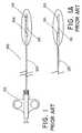
- the QUICK-CORE® needle 100is shown in FIGS. 1-1A .
- Needle 100includes a stylet 110 and an outer cannula 120 enclosing the stylet.
- Stylet 110has a tissue collecting or specimen notch 115 formed near the distal end of the stylet.
- Cannula 120has a sharpened point 124 at its distal end.
- the stylet 110 and the cannula 120are arranged so that the cannula point 124 is advanceable over the stylet 110 in order to cover the specimen notch 115 .
- Two-part biopsy needles having respective inner and outer members, such as stylet 110 and cannula 120are now well-known in the medical community.
- such needlesmay be activated by a spring-loaded handle 150 of a type disclosed, e.g., in U.S. Pat. No. 5,538,010.
- Activation of the spring-loaded handle 150causes rapid forward movement of the cannula 120 over the stylet 110 , and in particular, over the stylet notch 115 .
- This actionsevers a specimen of the prolapsed tissue into which the needle has been inserted, which specimen becomes retained in the specimen notch 115 of the stylet 110 .
- the cannulais retracted, and the tissue sample may be recovered from the stylet for further examination.
- This prior art needle assemblyworks very well for a variety of biopsy procedures.
- the ability of the needle to negotiate through curves in the vasculature, and particularly, the ability of the needle to avoid body structures and organs situated in the path of the needleis limited.
- use of the prior art assemblyis generally limited to a “straight shot” type of procedure, in which the needle is inserted percutaneously and directly advanced in generally linear fashion to a target lesion that is accessible without significant obstruction.
- a cutting devicesuch as a biopsy tissue-sampling needle
- a cutting instrumentof relatively simple design that enables the physician to obtain a tissue sample from a remote target site within the body of the patient in a manner that does not require passing the cutting instrument through obstructions that may be encountered along the pathway.
- the inventioncomprises a guidable cutting instrument for use in cutting a tissue specimen from a tissue mass.
- the cutting instrumentincludes a cannula having a proximal portion and a distal portion, the distal portion having a curve formed therealong; and a stylet having a proximal portion and a distal portion, the stylet distal portion having a specimen-receiving notch formed therein and having a curve formed therealong.
- the styletis received in the cannula and axially extendable therefrom, such that the notch is capable of penetrating the tissue mass.
- the cannulais axially movable over the extended stylet for severing the tissue specimen from the mass for capture in the notch.
- the cannula and styletare structured and arranged for relative rotation between a first position wherein the cannula curve and the stylet curve are in phase and the respective curves coincide to define a curved condition for a length of the cutting instrument, and a second position wherein one of the cannula curve and stylet curve is rotated relative to the other curve in a manner to define a generally linear condition of the cutting instrument.
- the inventioncomprises a method of retrieving a tissue specimen from a tissue mass of a patient.
- a tissue-penetrating cutting instrumentis provided.
- the cutting instrumentincludes a cannula having a proximal portion and a distal portion, wherein the distal portion has a curve formed therealong; and a stylet having a proximal portion and a distal portion, wherein the stylet distal portion has a specimen-receiving notch formed therein and has a curve formed therealong.
- the styletis received in the cannula, and is axially extendable therefrom, and the cannula is axially extendable over said extended stylet.
- the cannula and styletare structured and arranged for relative rotation therebetween from a first position wherein the cannula curve and the stylet curve are in phase and the respective curves coincide to define a curved condition for a distal portion of the cuffing instrument, and a second position wherein one of the curves is rotated relative to the other curve to define a generally linear condition of the cutting instrument.
- a distal end of the tissue-penetrating cutting instrumentis inserted into an interior space of the body of the patient, and the interior space is navigated under real time visualization such that the cutting instrument distal end approaches the tissue mass.
- the styletis advanced such that the notch extends beyond the cannula, and penetrates the tissue mass.
- the cannulais advanced over the notch to sever the specimen from the tissue mass, and to capture the severed specimen in the notch.
- the cutting instrumentis thereafter withdrawn, and the specimen is retrieved from the notch for examination.
- FIG. 1illustrates a prior art biopsy cutting instrument, showing an enlarged view of the distal portion of the cutting instrument
- FIG. 1Ais a side view of the distal portion of the cutting instrument of FIG. 1A , rotated 90 degrees from the view of FIG. 1 ;
- FIG. 2is a plan view of one embodiment of an inventive guidable surgical cutting instrument, wherein the respective stylet and outer cannula are oriented in phase, resulting in the curvature of the distal end of the cutting instrument;
- FIG. 3is a plan view of the guidable cutting instrument of FIG. 2 , following relative rotation of the respective stylet and outer cannula 180 degrees from the orientation of FIG. 2 , resulting in the straightening of the distal end of the cutting instrument;
- FIG. 4is a side view of the curved outer cannula of the needle assembly portion of the guidable cutting instrument of FIG. 2 ;
- FIG. 5is a side view of the curved inner stylet of the needle assembly portion of the guidable cutting instrument of FIG. 2 .
- proximal and distalwill be used to describe the opposing axial portions of the inventive cutting instrument, as well as the axial portions of various component features.
- proximalis used in its conventional sense to refer to the portion of the cutting instrument (or component thereof) that is closest to the operator during use of the cutting instrument.
- distalis used in its conventional sense to refer to the portion of the cutting instrument (or component thereof) that is initially inserted into the patient, or that is closest to the patient during use.
- FIG. 2illustrates a plan view of one embodiment of an inventive guidable cutting instrument 10 .
- guidable cutting instrument 10includes an outer cannula 30 , a tissue penetrating stylet 20 disposed within an inner passageway of the outer cannula, and a handle mechanism 40 . Only the distal tip portion 21 of stylet 20 that extends axially beyond the distal tip 31 of the cannula 30 is visible in this figure. In the view depicted in FIG. 2 , the respective distal ends of the stylet 20 and the outer cannula 30 are “in phase”, as further described herein. This arrangement results in the distal end of cutting instrument 10 having the curved configuration shown in the figure.
- FIG. 3is a plan view of the guidable cutting instrument of FIG. 2 , following relative rotation of the respective stylet and outer cannula 180 degrees from the orientation of FIG. 2 . As illustrated in FIG. 3 , this relative rotation results in the straightening of the distal end of the cutting instrument 10 when compared to the curved, “in phase”, configuration shown in FIG. 2 .
- FIG. 4is a side view of one embodiment of a curved cannula 30 suitable for use in the guidable cutting instrument 10 of FIG. 2 .
- cannula 30includes proximal and distal portions 32 , 34 , respectively.
- a hollow passageway(not shown) extends through cannula 30 .
- cannula 30may be a stainless steel tube having a diameter of about 0.330 inch and a wall thickness between about 0.010 and 0.001 inch.
- Cannula 30may also be constructed from any other suitable material including, but not limited to, metals, metal alloys such as nitinol, rigid or semi-rigid plastics, and composite materials.
- Cannulaesuch as cannula 30
- cannula 30for use in biopsy cutting instruments are well known in the art (see, e.g., FIGS. 1 and 1A ).
- Cannula 30may be formed of virtually any composition and have any dimensions known to be appropriate in prior art non-curved cannulae, as long as the cannula is capable of selective curvature in combination with a stylet, as described herein.
- Those skilled in the artare readily able to select a particular cannula composition for use in a particular application.
- the distal portion 34 of cannula 30comprises a shearing end 37 which terminates in a forward shearing tip 31 .
- shearing end 37tapers in the distal direction to tip 31 , as shown in the figure. More preferably, the shearing end comprises an annular, beveled edge about the distal portion 34 of cannula 30 .
- distal portion 34 of cannula 30When in the normal configuration shown in FIG. 4 , distal portion 34 of cannula 30 includes a curved segment.
- the curved segmentmay be formed in cannula 30 by methods well known in the art. Non-limiting examples of such methods include mechanical cold working/forming, and thermal setting of the material into the desired configuration.
- Distal portion 34is provided at a gentle angle of curvature from the main body of cannula 30 . Preferably, this angle is between about 5 and 45 degrees, and more preferably, about 10 degrees.
- the radius of curvaturewill preferably range between about 10 and 125 mm, and more preferably, about 60 mm.
- shearing end 37may be formed of a different material than that of the main cannula body.
- shearing end 37will generally will have a higher durometer (e.g., be harder) than the main body.
- shearing end 37can be formed of a material, such as a metal or metal alloy, having a relatively high hardness, and the main body of cannula 30 can be formed of a plastic having a lesser hardness. Shearing end 37 and distal portion 34 of the main cannula body can then be joined in any conventional manner, such as by adhesion.
- FIG. 5is a side view of the curved stylet 20 of the guidable cutting instrument 10 of FIG. 2 .
- Stylet 20is sized to be positioned within the hollow passageway of outer cannula 30 , and is arranged for axial movement therein.
- stylet 20comprises proximal and distal portions 22 , 24 , respectively.
- stylet 20may be stainless steel having a diameter of about 0.300 inch.
- the styletmay also be constructed from any other suitable material including, but not limited to, metals, metal alloys such as nitinol, rigid or semi-rigid plastics, and composite materials.
- Stylets, such as stylet 20for use in biopsy cutting instruments are well known in the art (see, e.g., FIGS. 1 and 1A ).
- Stylet 20may be formed of virtually any composition and have any dimensions known to be appropriate in prior art non-curved stylets, as long as the stylet is capable of selective curvature as described herein, and is capable of slidable, yet snug, receipt in the interior passageway of cannula 30 as described.
- Those skilled in the artare readily able to select a particular stylet composition for use in a particular application.
- stylet 20comprises a recessed channel or notch 25 along the distal portion 24 of the stylet.
- notch 25comprises oppositely facing edges 26 , 27 .
- Edges 26 , 27may be formed at any angle or depth to enable specimen notch 25 to hold a tissue specimen of adequate size for use in a conventional examination, such as a biopsy.
- the specimen notch 25has a length of up to about 3 to about 3.5 cm. More preferably, the notch has a length of about 1 cm to about 1.5 cm. Also, it is preferred that the notch 25 has a depth equal to about one half the stylet diameter.
- the stylet distal portion 24comprises a tapered end 27 which terminates in a piercing distal tip 21 .
- the tapered end 27comprises a tapered face having a cutting edge terminating in the forward piercing tip 21 .
- the piercing endmay alternatively be, e.g., cone-shaped. Formation of the notch 25 in the stylet may be accomplished in any conventional manner, such as by machining.
- the stylet distal end tipmay be sharpened by any conventional process, such as by grinding the tip in well-known fashion.
- the respective angular portions of the stylet 20 and cannula 30are selected and dimensioned in a manner such that when stylet 20 is positioned within the inner passageway of cannula 30 , the distal end of the resulting cutting assembly 10 achieves a particular configuration resulting from the rotational alignment of the individual curves of the respective stylet 20 and cannula 30 .
- Rotation of one of the stylet and cannula relative to the otherenables the distal end of the needle assembly to be selectively maneuvered to a curved configuration when the respective curved distal ends are coincident with each other, or “in phase”, as shown in FIG. 2 .
- the handle mechanism 40permits relative movement, both axially and rotationally, between the stylet 20 and the cannula 30 .
- the handle mechanismincludes an internal spring mechanism or other driver for permitting rapid axial movement of the cannula 30 over the stylet 20 in well known fashion, and/or for permitting axial movement of the stylet in the distal direction for sample collection purposes, as exhibited in conventional needle assemblies.
- Spring-loaded handle mechanisms permitting such relative movementare known in the art and are described, for example, in U.S. Pat. No. 5,538,010 and U.S. Patent Publication No. 2004/0133124 A1.
- Other examples of spring-loaded handlesare shown, e.g., in U.S. Pat. Nos. 4,958,625 and 5,195,533. All patent documents cited herein are incorporated by reference in their entirety.
- handle mechanism 40includes a trigger 44 , as well as finger grips 46 , 48 .
- Handle mechanism 40is provided with a dial 42 or a functionally similar feature for permitting relative rotation between stylet 20 and cannula 30 .
- cannula 30is rotationally engaged with dial 42 in a manner such that rotation of dial 42 by the operator causes a corresponding rotation of cannula 30 .
- This arrangementcan be accomplished in any conventional fashion, such as by joining the dial and cannula via the injection molding of the dial to the cannula, or by joining the components by way of an adhesive, such as an epoxy binder.
- stylet 20is not rotationally engaged with dial 42 and cannula 30 , and as a result, stylet 20 does not rotate upon rotation of dial 42 and cannula 30 .
- stylet 20is fastened to handle/lever 44 , and thereby, held from rotation. With minor modification, the relative rotation can be reversed from that described above. In this event, stylet 20 is rotatable, and outer cannula 30 is in a fixed, or non-rotatable, condition.
- the selective manipulation of the distal end 11 of the guidable cutting instrument 10 between the curved, in phase, configuration, and the straight, out of phase, configurationenables the physician to selectively alter the configuration of the distal end of the cutting instrument, and thereby avoid obstructions as the cutting instrument is advanced into the body of a patient under real time visualization.
- the physiciancan navigate the cutting instrument around the obstructions, and access a target tissue sample for removal without penetrating body organs or other impediments encountered within the body.
- the cutting instrumentretains the ability for the cannula 30 to move smoothly and freely over stylet 20 to sever a tissue specimen, thereby causing the sample to be captured in the notch.
- Such movementcan occur in either the curved alignment of the stylet 20 and cannula 30 as shown in FIG. 2 , or the straight alignment of the stylet and the cannula as shown in FIG. 3 . It is preferred that this movement occur in the curved position, as it is believed that this arrangement reduces drag between the stylet and cannula. This action facilitates rapid advancement of the outer cannula over the stylet. The faster the advancement, the better likelihood that the targeted tissue sample will be captured in the notch.
- the distal end of the cutting instrument 10is initially percutaneously inserted into the body of the patient in conventional manner, and under real time visualization. It is anticipated that ultrasound visualization will be the preferred manner of visualization. However, any other methods of visualization that are capable of providing suitable images may also be utilized.
- the distal end of the cutting instrumentwill be in either the curved configuration of FIG. 2 , or the straight configuration of FIG. 3 .
- the particular configuration selectedwill be derived from the particular image received from the UV monitor.
- the physicianwill advance the distal end of the cutting instrument under visualization until an obstruction, such as a body organ, is observed in the path of the needle.
- the physicianmay rotate dial 42 up to 180°, thereby manipulating the distal end of cutting instrument 10 up to the fully curved configuration illustrated in FIG. 2 (resulting from the 180° rotation), or to any curved configuration between the respective configurations of FIGS. 2 and 3 (resulting from a rotation less than 180°).
- the distal end of the instrumentcan be steered around the obstruction. Further manipulation in this fashion can be carried out to avoid additional obstructions, or to straighten the distal end following a successful navigation around an obstruction.
- the needlemay be activated in conventional fashion to sever the tissue sample of interest.
- the handlemay be activated such that stylet 20 is initially advanced beyond the distal end of the cannula 30 into the targeted tissue mass, wherein a segment of the tissue mass is prolapsed into the specimen-receiving notch 25 of the stylet.
- the handle trigger 44is then activated to rapidly advance the cannula over the stylet. This action of the cannula severs the tissue sample, and captures the sample in the notch.
- the cutting instrument having the sample captured thereinis then retracted from the body.
- the biopsy sampleis severed, it may be necessary to manipulate or navigate the needle upon removal in a generally reverse fashion when compared to the insertion method, in order to avoid obstructions. Following removal, the cannula is retracted, and the sample is recovered from the stylet notch for further examination.
- the above-described guidable cutting instrumentis merely one illustrative embodiment of the principles of this invention and that other cutting instruments may be devised without departing from the spirit and scope of this invention.
- the distal end of the cannula 30may be devised to include serrated teeth or a modified cutting edge for providing any number of different cutting or slicing actions.
- the distal end of stylet 20may be devised to achieve any number of different piercing actions.
Landscapes
- Health & Medical Sciences (AREA)
- Life Sciences & Earth Sciences (AREA)
- Medical Informatics (AREA)
- Engineering & Computer Science (AREA)
- Biomedical Technology (AREA)
- Heart & Thoracic Surgery (AREA)
- Pathology (AREA)
- Molecular Biology (AREA)
- Surgery (AREA)
- Animal Behavior & Ethology (AREA)
- General Health & Medical Sciences (AREA)
- Public Health (AREA)
- Veterinary Medicine (AREA)
- Surgical Instruments (AREA)
Abstract
Description
Claims (13)
Priority Applications (1)
| Application Number | Priority Date | Filing Date | Title |
|---|---|---|---|
| US12/468,306US8388550B2 (en) | 2009-05-19 | 2009-05-19 | Guidable cutting instrument |
Applications Claiming Priority (1)
| Application Number | Priority Date | Filing Date | Title |
|---|---|---|---|
| US12/468,306US8388550B2 (en) | 2009-05-19 | 2009-05-19 | Guidable cutting instrument |
Publications (2)
| Publication Number | Publication Date |
|---|---|
| US20100298737A1 US20100298737A1 (en) | 2010-11-25 |
| US8388550B2true US8388550B2 (en) | 2013-03-05 |
Family
ID=43125040
Family Applications (1)
| Application Number | Title | Priority Date | Filing Date |
|---|---|---|---|
| US12/468,306Active2030-03-16US8388550B2 (en) | 2009-05-19 | 2009-05-19 | Guidable cutting instrument |
Country Status (1)
| Country | Link |
|---|---|
| US (1) | US8388550B2 (en) |
Cited By (5)
| Publication number | Priority date | Publication date | Assignee | Title |
|---|---|---|---|---|
| WO2016049676A1 (en)* | 2014-10-03 | 2016-04-07 | Matthew Sampson | Surgical cutting device and methods of use thereof |
| WO2016070059A1 (en)* | 2014-10-31 | 2016-05-06 | Rutgers, The State University Of New Jersey | Transection device |
| WO2020100038A3 (en)* | 2018-11-12 | 2020-08-06 | Erez Nevo | Curved needle core biopsy system |
| US20210128122A1 (en)* | 2016-02-18 | 2021-05-06 | The Johns Hopkins University | Straight-insertion, forward-less fire, low noise, pneumatic soft tissue biopsy needle |
| US20210204921A1 (en)* | 2014-01-31 | 2021-07-08 | University Of Massachusetts | Microbiopsy device |
Families Citing this family (20)
| Publication number | Priority date | Publication date | Assignee | Title |
|---|---|---|---|---|
| US8361067B2 (en) | 2002-09-30 | 2013-01-29 | Relievant Medsystems, Inc. | Methods of therapeutically heating a vertebral body to treat back pain |
| US10028753B2 (en) | 2008-09-26 | 2018-07-24 | Relievant Medsystems, Inc. | Spine treatment kits |
| CA2737374C (en) | 2008-09-26 | 2017-03-28 | Relievant Medsystems, Inc. | Systems and methods for navigating an instrument through bone |
| WO2011011269A2 (en) | 2009-07-23 | 2011-01-27 | Waters Kendall R | Endoventricular injection catheter system with integrated echocardiographic capabilities |
| WO2011062736A1 (en)* | 2009-11-17 | 2011-05-26 | Cook Incorporated | Deflectable biopsy device |
| WO2012015771A2 (en)* | 2010-07-30 | 2012-02-02 | Cook Medical Technologies Llc | Rotating full-core biopsy needle |
| AU2012362524B2 (en) | 2011-12-30 | 2018-12-13 | Relievant Medsystems, Inc. | Systems and methods for treating back pain |
| US10588691B2 (en) | 2012-09-12 | 2020-03-17 | Relievant Medsystems, Inc. | Radiofrequency ablation of tissue within a vertebral body |
| RU2015118459A (en)* | 2012-10-19 | 2016-12-10 | Филлипп БРУННЕР | MEDICAL DEVICE CONTAINING A CURVED NEEDLE |
| WO2014071161A1 (en) | 2012-11-05 | 2014-05-08 | Relievant Medsystems, Inc. | System and methods for creating curved paths through bone and modulating nerves within the bone |
| US9724151B2 (en) | 2013-08-08 | 2017-08-08 | Relievant Medsystems, Inc. | Modulating nerves within bone using bone fasteners |
| EP2862520A1 (en)* | 2013-10-16 | 2015-04-22 | AprioMed AB | Biopsy device |
| US11172912B2 (en)* | 2014-09-23 | 2021-11-16 | Innovasci Llc | Biopsy needle and medical device incorporating the same |
| US10799265B2 (en)* | 2017-08-04 | 2020-10-13 | Lanfroi GRAZIANI | Re-entry device for peripheral arterial recanalization procedures |
| DE102017124795A1 (en)* | 2017-10-24 | 2019-04-25 | Meidrix Biomedicals Gmbh | Multi-part medical tool |
| AU2020346827A1 (en) | 2019-09-12 | 2022-03-31 | Relievant Medsystems, Inc. | Systems and methods for tissue modulation |
| EP4146085B1 (en)* | 2020-05-04 | 2024-10-09 | Bard Peripheral Vascular, Inc. | Biopsy apparatus |
| US12082876B1 (en) | 2020-09-28 | 2024-09-10 | Relievant Medsystems, Inc. | Introducer drill |
| EP4268150A4 (en) | 2020-12-22 | 2024-12-18 | Relievant Medsystems, Inc. | PREDICTION OF CANDIDATES FOR SPINAL NEUROMODULATION |
| US12433668B1 (en) | 2021-11-08 | 2025-10-07 | Relievant Medsystems, Inc. | Impedance stoppage mitigation during radiofrequency tissue ablation procedures |
Citations (29)
| Publication number | Priority date | Publication date | Assignee | Title |
|---|---|---|---|---|
| US3342175A (en) | 1964-11-23 | 1967-09-19 | Robert T Bulloch | Cardiac biopsy instrument |
| US3584624A (en)* | 1969-02-24 | 1971-06-15 | Vincent L De Ciutiis | Flexible intravenous catheter provided with cutting tip means |
| US4911148A (en) | 1989-03-14 | 1990-03-27 | Intramed Laboratories, Inc. | Deflectable-end endoscope with detachable flexible shaft assembly |
| US4945920A (en) | 1988-03-28 | 1990-08-07 | Cordis Corporation | Torqueable and formable biopsy forceps |
| US4958625A (en) | 1989-07-18 | 1990-09-25 | Boston Scientific Corporation | Biopsy needle instrument |
| US5095910A (en)* | 1990-04-18 | 1992-03-17 | Advanced Technology Laboratories, Inc. | Ultrasonic imaging of biopsy needle |
| US5152749A (en) | 1991-06-28 | 1992-10-06 | American Medical Systems, Inc. | Instrument placement apparatus |
| US5195533A (en) | 1992-05-08 | 1993-03-23 | Boston Scientific Corporation | Biopsy needle instrument for storing multiple specimens |
| US5313958A (en) | 1993-04-22 | 1994-05-24 | Alberto Bauer | Surgical biopsy instrument |
| US5318528A (en)* | 1993-04-13 | 1994-06-07 | Advanced Surgical Inc. | Steerable surgical devices |
| US5538010A (en) | 1994-10-05 | 1996-07-23 | Proact Ltd. | Biopsy needle device |
| JPH0984747A (en) | 1995-09-25 | 1997-03-31 | Olympus Optical Co Ltd | Ultrasonic endoscope |
| US5916175A (en) | 1996-01-26 | 1999-06-29 | Allegiance Corporation | Biopsy needle appliance and inserting guide with adjustable sample length and/or needle cutting stroke |
| US5951489A (en) | 1997-01-09 | 1999-09-14 | Allegiance Healthcare Corporation | Biopsy surgical appliance |
| US5968059A (en) | 1997-03-06 | 1999-10-19 | Scimed Life Systems, Inc. | Transmyocardial revascularization catheter and method |
| US5989196A (en) | 1994-10-31 | 1999-11-23 | Boston Scientific Corporation | Biopsy needle |
| US6024703A (en)* | 1997-05-07 | 2000-02-15 | Eclipse Surgical Technologies, Inc. | Ultrasound device for axial ranging |
| US6126633A (en) | 1997-07-11 | 2000-10-03 | Olympus Optical Co., Ltd. | Surgical instrument |
| JP2001190555A (en) | 1999-11-24 | 2001-07-17 | Marconi Medical Systems Inc | Needle biopsy system |
| US6425887B1 (en) | 1998-12-09 | 2002-07-30 | Cook Incorporated | Multi-directional needle medical device |
| US6595958B1 (en) | 2000-08-08 | 2003-07-22 | Scimed Life Systems, Inc. | Tortuous path injection device and method |
| US20040133124A1 (en)* | 2003-01-06 | 2004-07-08 | Cook Incorporated. | Flexible biopsy needle |
| US20040133168A1 (en) | 2002-12-23 | 2004-07-08 | Salcudean Septimiu E. | Steerable needle |
| US20040210209A1 (en) | 2001-02-13 | 2004-10-21 | Yeung Jeffrey E. | Treating back pain by re-establishing the exchange of nutrient & waste |
| US20060064062A1 (en) | 2004-09-22 | 2006-03-23 | Ravisankar Gurusamy | Transseptal puncture needles and needle assemblies |
| US7018343B2 (en) | 2002-04-05 | 2006-03-28 | Allegiance Corporation | Biopsy needle and biopsy device containing the same |
| US20070198043A1 (en) | 2006-02-22 | 2007-08-23 | Cox Daniel L | Bone marrow aspiration device |
| US7282020B2 (en) | 2001-04-24 | 2007-10-16 | Microspherix Llc | Deflectable implantation device and method of use |
| US7704234B2 (en)* | 2007-04-05 | 2010-04-27 | Darr Allan J | Dynaflex |
Family Cites Families (1)
| Publication number | Priority date | Publication date | Assignee | Title |
|---|---|---|---|---|
| US6428887B1 (en)* | 1998-01-30 | 2002-08-06 | Integument Technologies, Inc. | Adhesive oxyhalopolymer composites |
- 2009
- 2009-05-19USUS12/468,306patent/US8388550B2/enactiveActive
Patent Citations (29)
| Publication number | Priority date | Publication date | Assignee | Title |
|---|---|---|---|---|
| US3342175A (en) | 1964-11-23 | 1967-09-19 | Robert T Bulloch | Cardiac biopsy instrument |
| US3584624A (en)* | 1969-02-24 | 1971-06-15 | Vincent L De Ciutiis | Flexible intravenous catheter provided with cutting tip means |
| US4945920A (en) | 1988-03-28 | 1990-08-07 | Cordis Corporation | Torqueable and formable biopsy forceps |
| US4911148A (en) | 1989-03-14 | 1990-03-27 | Intramed Laboratories, Inc. | Deflectable-end endoscope with detachable flexible shaft assembly |
| US4958625A (en) | 1989-07-18 | 1990-09-25 | Boston Scientific Corporation | Biopsy needle instrument |
| US5095910A (en)* | 1990-04-18 | 1992-03-17 | Advanced Technology Laboratories, Inc. | Ultrasonic imaging of biopsy needle |
| US5152749A (en) | 1991-06-28 | 1992-10-06 | American Medical Systems, Inc. | Instrument placement apparatus |
| US5195533A (en) | 1992-05-08 | 1993-03-23 | Boston Scientific Corporation | Biopsy needle instrument for storing multiple specimens |
| US5318528A (en)* | 1993-04-13 | 1994-06-07 | Advanced Surgical Inc. | Steerable surgical devices |
| US5313958A (en) | 1993-04-22 | 1994-05-24 | Alberto Bauer | Surgical biopsy instrument |
| US5538010A (en) | 1994-10-05 | 1996-07-23 | Proact Ltd. | Biopsy needle device |
| US5989196A (en) | 1994-10-31 | 1999-11-23 | Boston Scientific Corporation | Biopsy needle |
| JPH0984747A (en) | 1995-09-25 | 1997-03-31 | Olympus Optical Co Ltd | Ultrasonic endoscope |
| US5916175A (en) | 1996-01-26 | 1999-06-29 | Allegiance Corporation | Biopsy needle appliance and inserting guide with adjustable sample length and/or needle cutting stroke |
| US5951489A (en) | 1997-01-09 | 1999-09-14 | Allegiance Healthcare Corporation | Biopsy surgical appliance |
| US5968059A (en) | 1997-03-06 | 1999-10-19 | Scimed Life Systems, Inc. | Transmyocardial revascularization catheter and method |
| US6024703A (en)* | 1997-05-07 | 2000-02-15 | Eclipse Surgical Technologies, Inc. | Ultrasound device for axial ranging |
| US6126633A (en) | 1997-07-11 | 2000-10-03 | Olympus Optical Co., Ltd. | Surgical instrument |
| US6425887B1 (en) | 1998-12-09 | 2002-07-30 | Cook Incorporated | Multi-directional needle medical device |
| JP2001190555A (en) | 1999-11-24 | 2001-07-17 | Marconi Medical Systems Inc | Needle biopsy system |
| US6595958B1 (en) | 2000-08-08 | 2003-07-22 | Scimed Life Systems, Inc. | Tortuous path injection device and method |
| US20040210209A1 (en) | 2001-02-13 | 2004-10-21 | Yeung Jeffrey E. | Treating back pain by re-establishing the exchange of nutrient & waste |
| US7282020B2 (en) | 2001-04-24 | 2007-10-16 | Microspherix Llc | Deflectable implantation device and method of use |
| US7018343B2 (en) | 2002-04-05 | 2006-03-28 | Allegiance Corporation | Biopsy needle and biopsy device containing the same |
| US20040133168A1 (en) | 2002-12-23 | 2004-07-08 | Salcudean Septimiu E. | Steerable needle |
| US20040133124A1 (en)* | 2003-01-06 | 2004-07-08 | Cook Incorporated. | Flexible biopsy needle |
| US20060064062A1 (en) | 2004-09-22 | 2006-03-23 | Ravisankar Gurusamy | Transseptal puncture needles and needle assemblies |
| US20070198043A1 (en) | 2006-02-22 | 2007-08-23 | Cox Daniel L | Bone marrow aspiration device |
| US7704234B2 (en)* | 2007-04-05 | 2010-04-27 | Darr Allan J | Dynaflex |
Cited By (7)
| Publication number | Priority date | Publication date | Assignee | Title |
|---|---|---|---|---|
| US20210204921A1 (en)* | 2014-01-31 | 2021-07-08 | University Of Massachusetts | Microbiopsy device |
| WO2016049676A1 (en)* | 2014-10-03 | 2016-04-07 | Matthew Sampson | Surgical cutting device and methods of use thereof |
| WO2016070059A1 (en)* | 2014-10-31 | 2016-05-06 | Rutgers, The State University Of New Jersey | Transection device |
| US10987127B2 (en) | 2014-10-31 | 2021-04-27 | Rutgers, The State University Of New Jersey | Transection device |
| US20210128122A1 (en)* | 2016-02-18 | 2021-05-06 | The Johns Hopkins University | Straight-insertion, forward-less fire, low noise, pneumatic soft tissue biopsy needle |
| WO2020100038A3 (en)* | 2018-11-12 | 2020-08-06 | Erez Nevo | Curved needle core biopsy system |
| US12318076B2 (en) | 2018-11-12 | 2025-06-03 | Erez Nevo | Curved needle core biopsy system |
Also Published As
| Publication number | Publication date |
|---|---|
| US20100298737A1 (en) | 2010-11-25 |
Similar Documents
| Publication | Publication Date | Title |
|---|---|---|
| US8388550B2 (en) | Guidable cutting instrument | |
| US10792022B2 (en) | Tissue sampling devices, systems and methods | |
| US9877708B2 (en) | Exchangeable core biopsy needle | |
| US6083237A (en) | Biopsy instrument with tissue penetrating spiral | |
| EP1428477B1 (en) | Control system for automated biopsy device | |
| US5823970A (en) | Biopsy needle set | |
| US20060122535A1 (en) | Method and device to obtain percutaneous tissue samples | |
| EP0720442B1 (en) | Multiple biopsy sampling coring device | |
| US10159470B2 (en) | Exchangeable core biopsy needle | |
| US10758213B2 (en) | Exchangeable core biopsy needle | |
| US9226734B2 (en) | Closed side-sampling biopsy device | |
| US20040133124A1 (en) | Flexible biopsy needle | |
| US11116483B2 (en) | Rotating biopsy needle | |
| US20140180164A1 (en) | Targetable biopsy needle set and method of using same | |
| JP6471904B2 (en) | Tissue and / or cell sampling device | |
| WO2002062226A1 (en) | Biopsy apparatus and method | |
| JP7703348B2 (en) | Rotatable tissue sampling device | |
| WO2002062231A2 (en) | Biopsy apparatus and method | |
| WO2002062230A1 (en) | Biopsy apparatus and method | |
| US20220104796A1 (en) | Biopsy needle assembly and method | |
| WO2021083843A1 (en) | Tissue biopsy device |
Legal Events
| Date | Code | Title | Description |
|---|---|---|---|
| AS | Assignment | Owner name:COOK INCORPORATED, INDIANA Free format text:ASSIGNMENT OF ASSIGNORS INTEREST;ASSIGNOR:KOEHLER, CLEVE;REEL/FRAME:022704/0629 Effective date:20090515 | |
| AS | Assignment | Owner name:COOK MEDICAL TECHNOLOGIES LLC, INDIANA Free format text:ASSIGNMENT OF ASSIGNORS INTEREST;ASSIGNOR:COOK INCORPORATED;REEL/FRAME:029398/0964 Effective date:20121119 | |
| STCF | Information on status: patent grant | Free format text:PATENTED CASE | |
| FPAY | Fee payment | Year of fee payment:4 | |
| MAFP | Maintenance fee payment | Free format text:PAYMENT OF MAINTENANCE FEE, 8TH YEAR, LARGE ENTITY (ORIGINAL EVENT CODE: M1552); ENTITY STATUS OF PATENT OWNER: LARGE ENTITY Year of fee payment:8 | |
| AS | Assignment | Owner name:WILMINGTON TRUST, NATIONAL ASSOCIATION, AS COLLATERAL AGENT, DELAWARE Free format text:SECURITY INTEREST;ASSIGNOR:COOK MEDICAL TECHNOLOGIES LLC;REEL/FRAME:066700/0277 Effective date:20240227 | |
| MAFP | Maintenance fee payment | Free format text:PAYMENT OF MAINTENANCE FEE, 12TH YEAR, LARGE ENTITY (ORIGINAL EVENT CODE: M1553); ENTITY STATUS OF PATENT OWNER: LARGE ENTITY Year of fee payment:12 |