US8388523B2 - Medical diagnostic instrument having portable illuminator - Google Patents
Medical diagnostic instrument having portable illuminatorDownload PDFInfo
- Publication number
- US8388523B2 US8388523B2US12/477,662US47766209AUS8388523B2US 8388523 B2US8388523 B2US 8388523B2US 47766209 AUS47766209 AUS 47766209AUS 8388523 B2US8388523 B2US 8388523B2
- Authority
- US
- United States
- Prior art keywords
- handle portion
- illuminator
- recited
- assembly
- instrument
- Prior art date
- Legal status (The legal status is an assumption and is not a legal conclusion. Google has not performed a legal analysis and makes no representation as to the accuracy of the status listed.)
- Active, expires
Links
- 239000000463materialSubstances0.000claimsabstractdescription18
- 239000004033plasticSubstances0.000claimsabstractdescription11
- 229920003023plasticPolymers0.000claimsabstractdescription11
- 230000008878couplingEffects0.000claimsdescription24
- 238000010168coupling processMethods0.000claimsdescription24
- 238000005859coupling reactionMethods0.000claimsdescription24
- 230000003287optical effectEffects0.000claimsdescription12
- 230000000717retained effectEffects0.000claimsdescription7
- 239000000654additiveSubstances0.000claimsdescription4
- 230000000996additive effectEffects0.000claimsdescription4
- 239000012530fluidSubstances0.000claimsdescription4
- 239000013533biodegradable additiveSubstances0.000claims1
- 238000005286illuminationMethods0.000description14
- 230000013011matingEffects0.000description14
- 230000008901benefitEffects0.000description10
- 238000013461designMethods0.000description10
- 238000012864cross contaminationMethods0.000description7
- 230000014759maintenance of locationEffects0.000description7
- 230000000712assemblyEffects0.000description5
- 238000000429assemblyMethods0.000description5
- 239000000835fiberSubstances0.000description4
- 230000006870functionEffects0.000description4
- 125000006850spacer groupChemical group0.000description4
- 230000007704transitionEffects0.000description4
- 230000004048modificationEffects0.000description3
- 238000012986modificationMethods0.000description3
- 230000035939shockEffects0.000description3
- 238000004140cleaningMethods0.000description2
- 230000007613environmental effectEffects0.000description2
- 239000006260foamSubstances0.000description2
- 229910052736halogenInorganic materials0.000description2
- 150000002367halogensChemical class0.000description2
- 230000007246mechanismEffects0.000description2
- 238000000034methodMethods0.000description2
- 230000001681protective effectEffects0.000description2
- 238000012800visualizationMethods0.000description2
- 239000004593EpoxySubstances0.000description1
- HBBGRARXTFLTSG-UHFFFAOYSA-NLithium ionChemical compound[Li+]HBBGRARXTFLTSG-UHFFFAOYSA-N0.000description1
- 239000004698PolyethyleneSubstances0.000description1
- 229910000831SteelInorganic materials0.000description1
- NIXOWILDQLNWCW-UHFFFAOYSA-Nacrylic acid groupChemical groupC(C=C)(=O)ONIXOWILDQLNWCW-UHFFFAOYSA-N0.000description1
- 230000009471actionEffects0.000description1
- XAGFODPZIPBFFR-UHFFFAOYSA-NaluminiumChemical compound[Al]XAGFODPZIPBFFR-UHFFFAOYSA-N0.000description1
- 229910052782aluminiumInorganic materials0.000description1
- 239000003990capacitorSubstances0.000description1
- 210000003679cervix uteriAnatomy0.000description1
- 230000008859changeEffects0.000description1
- 238000006243chemical reactionMethods0.000description1
- 239000007795chemical reaction productSubstances0.000description1
- 230000006835compressionEffects0.000description1
- 238000007906compressionMethods0.000description1
- 238000010276constructionMethods0.000description1
- 238000011109contaminationMethods0.000description1
- 238000011161developmentMethods0.000description1
- 239000003814drugSubstances0.000description1
- 230000009977dual effectEffects0.000description1
- 238000005516engineering processMethods0.000description1
- 239000006261foam materialSubstances0.000description1
- 230000017525heat dissipationEffects0.000description1
- 230000006872improvementEffects0.000description1
- 238000010348incorporationMethods0.000description1
- 238000010102injection blow mouldingMethods0.000description1
- 238000001746injection mouldingMethods0.000description1
- 238000003780insertionMethods0.000description1
- 230000037431insertionEffects0.000description1
- 238000002955isolationMethods0.000description1
- 229910001416lithium ionInorganic materials0.000description1
- 230000003278mimic effectEffects0.000description1
- 230000007935neutral effectEffects0.000description1
- -1polyethylenePolymers0.000description1
- 229920000573polyethylenePolymers0.000description1
- 238000009877renderingMethods0.000description1
- 238000012958reprocessingMethods0.000description1
- 238000007493shaping processMethods0.000description1
- 239000010959steelSubstances0.000description1
- 239000002699waste materialSubstances0.000description1
Images


Classifications
- A—HUMAN NECESSITIES
- A61—MEDICAL OR VETERINARY SCIENCE; HYGIENE
- A61B—DIAGNOSIS; SURGERY; IDENTIFICATION
- A61B1/00—Instruments for performing medical examinations of the interior of cavities or tubes of the body by visual or photographical inspection, e.g. endoscopes; Illuminating arrangements therefor
- A61B1/06—Instruments for performing medical examinations of the interior of cavities or tubes of the body by visual or photographical inspection, e.g. endoscopes; Illuminating arrangements therefor with illuminating arrangements
- A61B1/0661—Endoscope light sources
- A61B1/0684—Endoscope light sources using light emitting diodes [LED]
- A—HUMAN NECESSITIES
- A61—MEDICAL OR VETERINARY SCIENCE; HYGIENE
- A61B—DIAGNOSIS; SURGERY; IDENTIFICATION
- A61B1/00—Instruments for performing medical examinations of the interior of cavities or tubes of the body by visual or photographical inspection, e.g. endoscopes; Illuminating arrangements therefor
- A61B1/00064—Constructional details of the endoscope body
- A61B1/00105—Constructional details of the endoscope body characterised by modular construction
- A—HUMAN NECESSITIES
- A61—MEDICAL OR VETERINARY SCIENCE; HYGIENE
- A61B—DIAGNOSIS; SURGERY; IDENTIFICATION
- A61B1/00—Instruments for performing medical examinations of the interior of cavities or tubes of the body by visual or photographical inspection, e.g. endoscopes; Illuminating arrangements therefor
- A61B1/00142—Instruments for performing medical examinations of the interior of cavities or tubes of the body by visual or photographical inspection, e.g. endoscopes; Illuminating arrangements therefor with means for preventing contamination, e.g. by using a sanitary sheath
- A—HUMAN NECESSITIES
- A61—MEDICAL OR VETERINARY SCIENCE; HYGIENE
- A61B—DIAGNOSIS; SURGERY; IDENTIFICATION
- A61B1/00—Instruments for performing medical examinations of the interior of cavities or tubes of the body by visual or photographical inspection, e.g. endoscopes; Illuminating arrangements therefor
- A61B1/06—Instruments for performing medical examinations of the interior of cavities or tubes of the body by visual or photographical inspection, e.g. endoscopes; Illuminating arrangements therefor with illuminating arrangements
- A61B1/0661—Endoscope light sources
- A61B1/0669—Endoscope light sources at proximal end of an endoscope
- A—HUMAN NECESSITIES
- A61—MEDICAL OR VETERINARY SCIENCE; HYGIENE
- A61B—DIAGNOSIS; SURGERY; IDENTIFICATION
- A61B1/00—Instruments for performing medical examinations of the interior of cavities or tubes of the body by visual or photographical inspection, e.g. endoscopes; Illuminating arrangements therefor
- A61B1/227—Instruments for performing medical examinations of the interior of cavities or tubes of the body by visual or photographical inspection, e.g. endoscopes; Illuminating arrangements therefor for ears, i.e. otoscopes
- A—HUMAN NECESSITIES
- A61—MEDICAL OR VETERINARY SCIENCE; HYGIENE
- A61B—DIAGNOSIS; SURGERY; IDENTIFICATION
- A61B1/00—Instruments for performing medical examinations of the interior of cavities or tubes of the body by visual or photographical inspection, e.g. endoscopes; Illuminating arrangements therefor
- A61B1/233—Instruments for performing medical examinations of the interior of cavities or tubes of the body by visual or photographical inspection, e.g. endoscopes; Illuminating arrangements therefor for the nose, i.e. nasoscopes, e.g. testing of patency of Eustachian tubes
- A—HUMAN NECESSITIES
- A61—MEDICAL OR VETERINARY SCIENCE; HYGIENE
- A61B—DIAGNOSIS; SURGERY; IDENTIFICATION
- A61B1/00—Instruments for performing medical examinations of the interior of cavities or tubes of the body by visual or photographical inspection, e.g. endoscopes; Illuminating arrangements therefor
- A61B1/303—Instruments for performing medical examinations of the interior of cavities or tubes of the body by visual or photographical inspection, e.g. endoscopes; Illuminating arrangements therefor for the vagina, i.e. vaginoscopes
- A—HUMAN NECESSITIES
- A61—MEDICAL OR VETERINARY SCIENCE; HYGIENE
- A61B—DIAGNOSIS; SURGERY; IDENTIFICATION
- A61B1/00—Instruments for performing medical examinations of the interior of cavities or tubes of the body by visual or photographical inspection, e.g. endoscopes; Illuminating arrangements therefor
- A61B1/31—Instruments for performing medical examinations of the interior of cavities or tubes of the body by visual or photographical inspection, e.g. endoscopes; Illuminating arrangements therefor for the rectum, e.g. proctoscopes, sigmoidoscopes, colonoscopes
- A—HUMAN NECESSITIES
- A61—MEDICAL OR VETERINARY SCIENCE; HYGIENE
- A61B—DIAGNOSIS; SURGERY; IDENTIFICATION
- A61B1/00—Instruments for performing medical examinations of the interior of cavities or tubes of the body by visual or photographical inspection, e.g. endoscopes; Illuminating arrangements therefor
- A61B1/32—Devices for opening or enlarging the visual field, e.g. of a tube of the body
- A—HUMAN NECESSITIES
- A61—MEDICAL OR VETERINARY SCIENCE; HYGIENE
- A61B—DIAGNOSIS; SURGERY; IDENTIFICATION
- A61B3/00—Apparatus for testing the eyes; Instruments for examining the eyes
- A61B3/0008—Apparatus for testing the eyes; Instruments for examining the eyes provided with illuminating means
Definitions
- the applicationrelates to the field of diagnostic medicine and more particularly to various medical instruments that is configured to releasably support a portable illuminator so as to prevent cross-contamination between patients and in which the supported illuminator is releasably retained within the handle of the instrument and optically coupled with the instrument.
- the portable illuminatorcan be used interchangeably with a plurality of various hand-held medical diagnostic instruments.
- the portable illumination assemblyincludes a resident power supply and a compact light source that are each integrated within a single housing, wherein the illumination assembly can be positioned at least partially within the elongated cavity of a vaginal speculum handle.
- the illumination assemblyWhen positioned within the cavity of the speculum handle, the illumination assembly optically couples with the proximal end of a light pipe that is formed in the upper portion of the cavity of the speculum handle.
- the light pipeis defined by a distal light-emitting end that directs sufficient light from the attached illuminator to a medical target (e.g., the cervix of the patient).
- a hand-held medical diagnostic instrument assemblycomprising a hand-held medical diagnostic instrument, the instrument including an instrument head and a handle portion.
- the handle portionincludes an open-ended receiving cavity.
- the compact illuminatorhas a compact light source and a power supply each disposed within a housing.
- the illuminatoris sized to fit substantially within the receiving cavity in releasable fashion, the handle portion further including means for optically coupling the light source of a retained illuminator with the instrument head.
- the optical coupling meansincludes a surface formed at a top of the receiving cavity bridging said handle portion and the interior of said instrument head, wherein the surface provides a fluid seal relative to the interior of said instrument head, and wherein the surface further having optical quality to enable the light source of the compact illuminator to be coupled to the instrument head when the illuminator is assembled within the handle portion.
- the handle portionis releasably attached to said instrument head. According to another version, the handle portion is integral to the instrument.
- the handle portionis releasably attached, the handle portion is releasably attachable in multiple axial orientations relative to the instrument head.
- the open-ended receiving cavityin one version includes at least one guide rail, the at least one guide rail including a ramped surface within the deformable portion of the handle portion for engaging the compact illuminator when deformed to facilitate release of the illuminator.
- the receiving cavitycan also include at least one heat dissipating rib.
- the at least one heat dissipating ribalso can serve as guide rails in said receiving cavity for the compact illuminator.
- the optical coupling meanscan include a socket defined at the top of the handle portion, the socket including the surface.
- the surfaceis configured to have optical power.
- the socketcan include means for guiding the portable illuminator into alignment with said surface when said illuminator is inserted into the receiving cavity. The socket enables the handle portion to be releasably attachable to the instrument head.
- the handle portioncan include at least one retaining feature for retaining said illuminator in said receiving cavity.
- the handle portionfurther includes at least one feature for facilitating release of the portable illuminator from the handle portion.
- at least a portion of said handle portioncan be flexibly deformable.
- the medical diagnostic instrumentis preferably from at least one of the group consisting of a sigmoidoscope, an anoscope, an ophthalmoscope and an otoscope.
- the handle portionis manufactured from a plastic material, wherein the handle portion can be disposable and moreover in which the handle portion is biodegradable or treated with an additive that renders the handle portion biodegradable.
- the portable illuminatoraccording to one version is automatically energized when said compact illuminator is inserted in said receiving cavity.
- the portable illuminatorcan be automatically deenergized when the illuminator is removed from the receiving cavity.
- a handle portion for a medical diagnostic instrumentincluding a housing having an open-ended receiving cavity that is sized to receive a portable illuminator.
- the handle portionis releasably couplable to the body of the medical diagnostic instrument wherein in which at least a portion of the handle portion is flexibly deformable.
- a diagnostic instrument systemthat comprises a plurality of hand-held medical diagnostic instruments, each of the diagnostic instruments including a handle portion having an open-ended receiving cavity and an instrument head, and a portable illuminator separably and releasably couplable within the open-ended receiving cavity of each of the hand-held diagnostic instruments.
- Each said handle portionincludes means for optically coupling the portable illuminator with the instrument head to deliver light to a medical target.
- One advantage of the herein described assemblyis greater degree of user versatility achieved by providing at least one medical diagnostic instrument that releasably accepts a portable illuminator. Another advantage provided is greater ease of use of hand-held diagnostic instruments so equipped. Yet another advantage is the ability to develop disposable component(s) to prevent cross contamination during procedures and thereby substantially eliminate time and expense of reprocessing and cleaning.
- instruments so configuredcan be provided with improved and consistent ergonomics, enabling better “feel” for the user.
- portability of a common illuminatorenables selectivity of light sources, such as LEDs, providing greater selectivity between different color temperatures and therefore affording choices as to illumination sources and enabling improvements to be added simultaneously to a family of instruments. As such, improved visualization of an examination area is possible by supplying whiter, brighter light.
- the handle portioncan be made disposable, but without creating environmental issues.
- FIG. 1is a perspective view of numerous prior art medical diagnostic instruments, including a tethered illumination assembly for use therewith;
- FIG. 2is a side view, shown in section, of a portable illuminator for use with at least one medical diagnostic instrument;
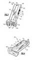
- FIG. 3is a bottom perspective view of the portable illuminator of FIG. 2 ;
- FIG. 4is a front perspective view of the portable illuminator of FIGS. 2-3 ;
- FIG. 5is an enlarged bottom perspective view of the portable illuminator of FIGS. 2-4 ;
- FIG. 6is a schematic partial view of a medical diagnostic instrument assembly in accordance with one embodiment, including a medical diagnostic instrument having a handle portion that is configured to substantially receive the portable illuminator of FIGS. 2-5 (shown as partially inserted into the handle portion);
- FIG. 6( a )illustrates the medical diagnostic instrument assembly shown schematically in FIG. 6 , as unassembled
- FIG. 6( b )illustrates an assembled version of the instrument assembly of FIG. 6( a );
- FIG. 7is a top plan view of a handle portion for use with the medical diagnostic instrument of FIG. 6 ;
- FIG. 8is a bottom view of the handle portion of FIG. 7 ;
- FIG. 9is a sectioned front elevational view of the handle portion of FIGS. 7 and 8 ;
- FIG. 10is a side elevational view of the handle portion of FIGS. 7-9 ;
- FIG. 11is a front elevational view of the handle portion of FIGS. 7-10 ;
- FIG. 12is a partially exploded view illustrating the portable illuminator of FIGS. 2-5 and the handle portion of FIGS. 7-11 ;
- FIGS. 12( a ) and 12 ( b )illustrate views of the portable illuminator of FIGS. 2-5 and the handle portion of FIGS. 7-12 in an assembled and unassembled condition, respectively;
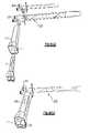
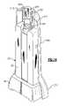
- FIG. 13is an enlarged view of the upper mating end of the handle portion of FIGS. 7-12 ;
- FIG. 14is a partial front perspective view of the compact illuminator as positioned in the handle portion of FIGS. 7-13 , the handle being shown partially cutaway;
- FIG. 15is an enlarged section view of the cutaway handle portion of FIG. 14 , including an enclosed portable illuminator;
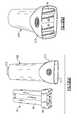
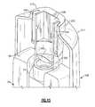
- FIG. 16illustrates a cutaway partial perspective view of the handle portion of FIGS. 7-15 ;
- FIG. 17is a partial sectioned side elevational view of the handle portion of FIGS. 7-16 , including a portable illuminator disposed therein;
- FIG. 18is a partial bottom perspective section view of the handle portion and portable illuminator of FIG. 17 ;
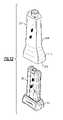
- FIG. 19is a front perspective view of a handle portion which is made in accordance with another embodiment.
- FIG. 20is a top perspective view of a handle portion made in accordance with yet another embodiment
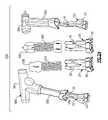
- FIG. 21illustrates a group of various medical diagnostic instruments each having handle portions made in accordance with embodiments of this application and configured to retain the portable illuminator of FIGS. 2-5 ;
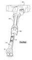
- FIG. 22illustrates a medical diagnostic instrument from the group shown in FIG. 21 in which a prior art instrument is compared to a medical diagnostic instrument having a handle portion made in accordance with an embodiment of the present invention
- FIG. 22( a )depicts an assembled view of a laryngnoscope similar to that shown in the group of instruments shown in FIG. 22 ;
- FIG. 23illustrates another of the diagnostic instruments from the group shown in FIG. 21 in accordance with the prior art as compared to diagnostic instruments, each having a handle portion made in accordance with an embodiment of the present invention
- FIG. 24illustrates another group of various medical diagnostic instruments made in accordance with embodiments of this application and configured to retain a portable illuminator
- FIG. 24( a )illustrates a partially exploded view of an ophthalmoscope of FIG. 24 having a handle portion that is configured to receive a portable illuminator;
- FIG. 25illustrates a pair of medical diagnostic instruments (ophthalmoscope and otoscope) in accordance with the prior art as compared to various embodiments made in accordance with the present invention
- FIG. 25( a )is a partially exploded view of an otoscope of FIGS. 24 and 25 having a handle portion configured to receive a portable illuminator;
- FIG. 26illustrates another medical diagnostic instrument in accordance with the prior art as compared to an instrument which is made in accordance with another embodiment
- FIG. 27depicts an assembly including the handle portion of FIG. 19 as used with sigmoidoscopes and anoscopes;
- FIG. 28is a schematic view of a medical diagnostic instrument assembly in accordance with an alternative embodiment, the assembly including a medical instrument having a handle portion that is configured to receive the portable illuminator (shown partially inserted into the handle portion) of FIGS. 2-5 .
- a group 300 of prior art hand-held medical diagnostic instrumentsin this instance, a sigmoidoscope 304 and an anoscope 312 .
- Each of the depicted diagnostic instruments 304 , 312 in this group 300is commonly defined by an instrument head 314 , 318 .
- Each instrument head 314 , 318includes at least one engagement feature enabling the releasable attachment of a handle portion 322 to a lower end thereof and a sigmoidoscope body (such as 320 , 324 that are selectively attachable to the distal end of the sigmoidoscope instrument head 314 ).
- the handle portion 322includes a cord 326 and transformer 320 that permits a tethered connection to a non-compact power source (such as an AC wall power supply, not shown), to energize a light source (not shown) provided in the handle portion 322 in order to permit light to be effectively transmitted to the instrument head 314 , 318 , thereby permitting patient examination.
- a non-compact power sourcesuch as an AC wall power supply, not shown
- a light sourcenot shown
- the following embodimentsrelate to various hand-held diagnostic instruments having a handle portion defined by an open lower or bottom end and a hollow interior including an elongated cavity, which is sized and configured to releasably retain a compact illuminator.
- the handle portioncan be releasably attached to the remainder of a medical diagnostic instrument or made integral therewith.
- the handle portioncan also be one of disposable (single use or single-patient use) and reusable.
- the exemplary portable illuminator 20is defined by a housing 24 having a substantially hollow interior that is sized to retain a number of components, as described below, including at least one portable light source and at least one portable power supply.
- the portable light sourceis a miniature white LED 28 , such as, for example, those manufactured and sold by Nichia America, Inc. and Lumileds, Inc., while the portable power source includes at least one rechargeable battery 32 , such as, for example, a Model UF612248PJFH lithium-ion battery manufactured by Sanyo Corp, the battery having suitable characteristics to sufficiently power the LED 28 .
- the use of an LED 28is preferred to make the illuminator “portable”; that is, such that it is not tethered (i.e., corded) and therefore does not require a non-portable power source, such as a wall transformer or AC power supply, and wherein the illuminator 20 functions as an integrated unit.
- a non-portable power sourcesuch as a wall transformer or AC power supply
- the housing (also commonly referred to throughout as a “body section”) 24 of the portable illuminator 20is manufactured from a lightweight, durable material, such as a moldable plastic, and is further defined by an upper housing portion 36 and a lower base portion 40 .
- the housing 24is made from a two piece shell-like structure that is ultrasonically welded or otherwise connected together. Other structural forms and shaping of the housing 24 , however, should be readily apparent.
- a battery compartmentcould be provided having a removable cover (not shown), if desired, for removing and replacing the rechargeable battery 32 , as needed.
- the upper housing portion 36is defined by a relatively flat, thin (low profile) enclosure having a substantially constant thickness and width wherein each of these dimensions is approximately equal to that of the contained battery 32 .
- the lower base portion 40is significantly wider than that of the upper housing portion 36 , the former expanding from a maximum width adjacent a bottom surface 165 to a minimum width adjacent the bottom of the upper housing portion.
- the transition from the top to the bottom of the lower base portion 40takes the form of a substantially trapezoidal shape, as viewed from the side of the illuminator 20 ; see FIG. 4 .
- This specific transitionprovides an ergonomic design and further assists in positioning and retaining the illuminator 20 within the receiving cavity defined in the handle section of at least one medical diagnostic instrument, as described in greater detail below, as well as a charging station (not shown) used to recharge the rechargeable battery 32 . This transition also assists in the removal of the illuminator 20 from the handle portion, as described in greater detail below.
- the LED 28is retained herein within a substantially cylindrical region 44 projecting from the top of the upper housing portion 36 .
- the cylindrical projecting region 44preferably surrounds the lens envelope (not shown) of the LED 28 , as well as a front lens element 34 , wherein the cylindrical projecting region protects both the LED and lens element from shock, impact and associated loads.
- the LED 28is further housed within a retaining structure 49 wherein the electrical contacts of the LED are attached to a flexible circuit assembly 96 , one end portion of which covers a heat sink 54 .
- the heat sinkis being made from aluminum or other material with suitable heat conductivity properties that is disposed between the battery 32 and LED 28 , wherein each of the foregoing elements are disposed within the upper housing portion 36 .
- the remainder of the flexible circuit assembly 96extends downwardly across one facing side of the illuminator 20 to the bottom of the lower base portion 40 .
- the electrical contacts (not shown) extending from the LED 28are attached to the flexible circuit assembly 96 using a thermal epoxy, such as, for example, Emerson Cuming Stycast 2850, such that the contacts also conduct heat away from the LED 28 to the heat sink 54 .
- the retaining structure 49can include an interior reflective surface (not shown) used to assist in directing light towards the front lens element 34 .
- the heat sink 54includes a lateral recess 56 that permits the inclusion of a retention pin 58 having a beveled end 62 that extends outwardly from one lateral side of the housing 24 .
- the beveled end 62 of the retention pin 58is biased outwardly by means of a spring 60 .
- a spacer 94having a layer of soft foam material provided on upper and lower facing sides thereof, is disposed between the bottom of the heat sink 54 and the battery 32 , this spacer also providing isolation between the heat sink 54 and battery 32 from impact and shock loads being applied to the illuminator 20 .
- a flexible circuit assembly 96is provided in relation to the LED 28 , an upper end portion of this assembly being folded about the heat sink 54 and extending along the interior wide side of the illuminator 20 .
- a slide switch 66is vertically arranged within a slotted area 70 such that the switch is mainly recessed and does not extend beyond the exterior of the lateral side 25 with the exception of a pair of tabs 74 disposed at respective ends of the exterior surface of the switch.
- the slide switch 66is biased in an off position by means of a switch spring 78 attached to a leaf spring 86 extending along substantially the entire lateral side of the housing 24 .
- the leaf spring 86is formed into a bump onto which a dowel pin 84 is disposed.
- the lower end of the leaf spring 86is attached to the switch spring 78 , the switch spring being further disposed in relation to a switch 98 that is attached to a printed circuit board 92 .
- the lower base portion 40further permits the printed circuit board 92 to be supported horizontally (i.e., perpendicular to the major dimension of the battery 32 ) and retained by a pair of channels 95 .
- the lower end portion of the flexible circuit assembly 96is disposed in overlaying relation over the bottom of the printed circuit board 92 , this portion of the flexible circuit assembly including a pair of integral electrical contacts 100 that extend outwardly from the bottom of the housing 24 . Providing each of the electrical contacts 100 integrally on the flexible circuit board assembly 96 provides savings in terms of the overall space envelope of the portable illuminator 20 .
- the electrical contacts 100employ a bi-polar diode bridge, thereby enabling the illuminator 20 to be oriented relative to a suitable interface with regard to at least one electrical device, as described in greater detail in U.S. Ser. No. 11/731,631, the entire contents of which are herein incorporated by reference.
- the circuit board 92includes a power conversion means, for example, a buck-boost constant current LED driver, such as Model LTC 3453UF; which drives the LED 28 with substantially constant current over the useful voltage limits of the contained battery 32 (e.g., 4.2 volts for a charged battery, 2.4 volts for a nearly depleted battery).
- a battery connector 104is also connected to the top surface of the printed circuit board 92 and the battery 32 , wherein the circuit board further includes a protection or safety circuit to prevent shorting and over charging of the contained battery, such as, for example, a Model UCC 3952-PW-1, manufactured by Texas Instruments, Inc.
- a current charge limiteris also included to prevent the portable illuminator 20 from being charged by an electrical device (not shown) that is connected to the electrical contacts 100 while the illuminator 20 is enabled.
- a low-battery LED indicator assembly 108attached to the printed circuit board 92 , includes a window 112 that is disposed in a lateral side of the lower base portion 40 .
- the window 112provides an indication to a user when the contained battery 32 is either charged or in need of charge, such as, for example, through flashing or a change in color of the LED, in a manner that is known to those in the field.
- the low-battery LED indicator assembly 108can illuminate one color (e.g., yellow) through the window 112 when 10 minutes of “on” time remains and a second color (e.g., red) when 5 or less minutes of time remains. It should be readily apparent that other similar configurations can be contemplated.
- the upper housing portion 36includes a pair of shoulders 48 spaced evenly apart from the cylindrical projecting region 44 on opposing lateral sides thereof.
- Each of the shoulders 48extends upwardly, according to the embodiments described herein, such that the top surface of each shoulder is substantially coplanar with or slightly above the top of the cylindrical projecting region 44 .
- the shoulders 48therefore provide an additional means to protect the portable illuminator 20 , and particularly the contained LED 28 and lens element 34 , from impact, shock and associated loads.
- the herein described illuminator 20can withstand damage from drops from as high as 4 feet.
- the shoulders 48 and the substantially cylindrical projecting region 44also permit the portable illuminator 20 to be inserted only to a predetermined distance within a handle portion of a diagnostic instrument as described in greater detail below.
- the bottom surface 165 of the portable illuminator 20includes a recessed surface portion 167 , defining an interface 166 that includes the pair of electrical contacts 100 extending outwardly therefrom.
- a transverse rib 169is further provided between the pair of electrical contacts 100 and disposed in approximately the center of the bottom surface 165 .
- a pair of side walls 180defines the transition between the recessed surface portion 167 and the bottom or base surface 165 of the illuminator 20 .
- Each of the side walls 180is inwardly angled, according to this embodiment; that is, each of the side walls further comprise a pair of angled segments 181 , 182 , extending laterally outward relative to a centerline 168 that runs perpendicular to the axis of the transverse rib 169 .
- This interface 166FIG. 5 , is matingly engageable with various electrical devices, as described in greater detail in previously incorporated U.S. Ser. No. 11/731,631, including an auxiliary power module plug (not shown) and a charging station (not shown), wherein the interface enables the recessed electrical contacts 100 to remain substantially clean during use.
- the herein described illuminator 20can also be used independently without connection to a medical diagnostic instrument for purposes of use as a portable examination light.
- the medical diagnostic instrumentin this case, a sigmoidoscope 200 , includes an elongated instrument head 204 and a coupled handle portion 208 .
- the handle portion 208according to this embodiment is releasably attached or coupled with an engagement portion 223 , such as a post projecting outwardly from the bottom of the elongated instrument head 204 .
- the releasability of the handle portion to the remainder of the instrumentis a desirable though is not an essential feature for purposes of retaining the illuminator 20 . That is, the handle portion could also be made integral with one or the remainder of any of a plurality of medical diagnostic instrument(s), as shown in FIG. 28 .
- FIGS. 7-11An exemplary handle portion 208 is depicted in FIGS. 7-11 , which is used in conjunction with the portable illuminator 20 , as further shown in an assembled condition in FIGS. 12 and 14 - 18 .
- the handle portion 208is made from a formable, durable, lightweight plastic, such as polyethylene or other suitable material, and can be manufactured, such as through an injection-molding or blow-molding process.
- the handle portion 208can be treated with a so-called “green” (i.e., biodegradable) material; for example an additive such as Nature Works 3001 PLA, although other materials could also be contemplated provided they are lightweight, preferably biocompatible and relatively durable.
- the additiveenables the treated handle portion 208 to become a biodegradable end product over time.
- the handle portion 208 according to this embodiment and shown more particularly in FIGS. 7-11is generally defined by an upper coupling housing section 211 and a lower receiving section 213 , the latter including an open end 215 extending into an elongated receiving cavity 217 , FIGS. 9 and 12( a ).
- the upper coupling and lower receiving housing sections 211 , 213 of the handle portion 208 according to this embodimentsubstantially mimic the shape (i.e., the upper housing portion 36 , FIG. 2 , and lower base portion 40 , FIG. 2) of a portable illuminator 20 , FIG. 6 , which can be releasably introduced into the elongated receiving cavity 217 , FIG. 12( a ).
- the receiving cavity 217is sized to substantially accommodate the entire length of the portable illuminator 20 .
- the upper coupling section 211is further defined by a mating upper end 212 , more clearly shown in FIGS. 7 and 10 - 15 , which projects outwardly from the top of the handle portion 208 .
- An interior cylindrical section 232 of the mating end 212comprises a center cavity 228 which is formed therein, the section further comprising an upper portion 250 and a tubular lower portion 240 that includes a lower surface 246 .
- the center cavity 228extends through the entirety of the upper portion 250 and the tubular lower portion 240 with the exception of the lower surface 246 , which according to this exemplary embodiment is itself a thinned section or web of the molded handle portion 208 .
- the lower surface 246provides two functions.
- this surfacein combination with the remainder of the top of the handle portion provides a fluid seal with respect to the interior of the instrument head when the handle portion is attached thereto.
- the thinned material of the lower surfaceprovides optical transmissivity and enables optical coupling between the contained light source of the portable illuminator 20 and the instrument head 204 .
- the remainder of the herein described handle portion 208is generally opaque while the thinning of the plastic web forming the lower surface 246 produces a generally transparent structure.
- this thinned surfacecan also be shaped in order to provide optical power; in this case, the surface is shaped as a lens.
- the upper coupling section portion 250 of the herein described upper coupling section 211further includes a pair of slots 254 , FIG. 13 , that are formed on opposite sides of the center cavity 228 .
- Each of the slots 254creates flexures 221 in conjunction with the center cavity 228 that are used for engagement with an engagement feature 223 , FIG. 6 , of the diagnostic instrument 200 , as described below.
- the lateral interior sides of the handle portion 208 within the receiving cavity 217includes a set (e.g., four, but only two actually shown in this cutaway view) of parallel spaced guide rails 260 that extend substantially along the entire length of the upper housing section 211 , as well as a pair of center rails 264 (only one shown in this cutaway figure) along opposite lateral sides that additionally extend partially into the lower receiving section 213 .
- the center rails 264are each defined by a lower ramped surface 268 , the purpose of which will be described in greater detail below. Additionally, the foregoing rails 264 also provide a dual function in that these surfaces act as fins so as to provide a means for heat dissipation as to a contained compact illuminator 20 , FIG. 2 .
- the portable illuminator 20is sized to fit substantially within the elongated receiving cavity 217 of the handle portion 208 wherein the cylindrical projecting region 44 at the top of the upper housing portion 36 is sized to fit within the confines of the lower tubular section 240 of the mating end 212 .
- the spacings 47 , FIG. 2 , between the shoulders 48 of the illuminator 20form stops with the tubular lower section 240 and bring the cylindrical projecting region 44 and the contained LED 28 , FIG. 6 , into optical alignment with the lower surface (lens) 246 .
- the parallel rails 260assist in guiding the illuminator 20 into position, wherein the illuminator can be introduced in one of two different (e.g., opposite) axial orientations that are 180 degrees apart from one another, enabling versatility in assembly by an operator (not shown).
- an interior tooth or prong(not shown) that is provided on an interior surface of the elongated cavity 217 provides positive engagement when the illuminator 20 has been fully engaged within the handle portion against the retention pin 58 , FIG. 2 .
- the post-like engagement feature 223 , FIG. 6 , of the instrument 200extends outwardly from the bottom of the instrument head 204 and is attached to the mating end 212 such that the engagement feature is fitted within the center cavity 228 of the upper portion 250 thereof.
- the flexures 221 defined by the slots 254outwardly flex and permit the engagement feature to be positively engaged in a releasable fashion.
- sliding the portable illuminator 20 axially into position in the elongated receiving cavity 217 of the handle portion 208causes the contained LED 28 , FIG. 2 , to be energized automatically as a result of the movement of the biased slide switch 66 , FIG. 2 , and as further described in U.S. Ser. No. 11/731,631, and U.S. Ser. No. 11/731,189, incorporated by reference herein in their entirety. This is further shown in FIG. 6( b ), upon movement a predetermined distance within the receiving cavity 217 .
- the portable illuminator 20can be selectively released from the herein described assembly by squeezing the lower portion 213 of the handle portion 208 , as shown by arrows 219 , FIG. 6 .
- the flexible nature of the handle portion 208produces localized inward deformation of the lower portion 213 relative to the remainder of the handle portion 208 , causing the lower base portion 40 , FIG. 2 , of the portable illuminator 20 to be guided from the confines of the receiving cavity 217 through the open end by engagement by the ramped surfaces 268 of the rails 264 against the illuminator housing overcoming the force of the interior tooth (not shown).
- the biased slide switch 66is automatically moved to a neutral position that deenergizes the contained LED 28 .
- the herein described handle portion 208effectively becomes a protective sheath for the contained portable illuminator 20 during examination and protects the illuminator from fluid or other cross contamination from the patient.
- the handle portion 208can be releasably removed from the remainder of the diagnostic instrument 200 by releasing engagement feature 223 from the mating end 212 wherein the handle portion can then be discarded.
- the engagement slot 254 and flexures 221 of the mating end 212 of the handle portion 208can be made such that disengagement from the instrument 200 disables these features, rendering the handle portion 208 ineffective and thereby preventing reuse after a single attachment/engagement or after a few or predetermined number of attachments to the instrument 200 .
- FIGS. 19 and 20Alternative handle portion designs 280 , 290 are representively illustrated in FIGS. 19 and 20 .
- Each of these designscommonly include an upper coupling section 284 , 294 , a lower receiving section 286 , 296 having an open end 287 , 297 and a mating end 288 , 298 .
- a portable illuminator 20FIG. 2
- each handle portion 280 , 290a set of heat dissipative ribs 283 , 293 are provided on the exterior of each handle portion 280 , 290 .
- the handle portioncan be made integral with the remainder of an instrument, as shown in FIG. 28 , to further illustrate possible variations that are contemplated herein.
- FIG. 21One such group of instruments is depicted in FIG. 21 including a laryngoscope 404 , a set of anoscopes 440 (a standard anoscope and an operating anoscope being shown), and a vaginal speculum 480 , each of which can be commonly or similarly configured to receive a portable illuminator 20 , FIG. 2 , or in conjunction with a disposable handle portion, such as the handle portion 280 previously depicted in FIG. 19 , by way of example.
- a laryngoscope 404a set of anoscopes 440 (a standard anoscope and an operating anoscope being shown)
- a vaginal speculum 480each of which can be commonly or similarly configured to receive a portable illuminator 20 , FIG. 2 , or in conjunction with a disposable handle portion, such as the handle portion 280 previously depicted in FIG. 19 , by way of example.
- vaginal speculum 480has been previously described in PCT/US2006/012116 and is shown herein to further illustrate the overall versatility that can be created for a family of instruments configured according to the present invention.
- Each of the above instrumentscommonly includes a handle portion having a receiving cavity that is sized to substantially enclose the illuminator.
- a prior art laryngoscope 420depicted on the right hand side of this figure, is contrasted with the laryngoscope 404 shown in FIG. 21 .
- the prior art laryngoscope 420is defined by a body 424 , which includes an integrated elongated handle 426 with an open end 427 that requires the insertion of a cartridge 430 .
- the cartridge 430is an electrically conductive (e.g., steel) cylindrical member that retains a set of stacked batteries (not shown), as well as a halogen light source (not shown), the cartridge being retained within the handle 426 by means of a cap 434 that is attached to the open end 427 of the handle.
- the laryngoscope 404is defined by a plastic body 405 that includes an integrated handle portion 408 according to this exemplary embodiment, the handle portion having an open-ended elongated receiving cavity 406 which is sized to substantially fit the upper housing section of a portable illuminator 20 , FIG. 2 .
- prior art anoscopes 460 , 470are contrasted with the set of anoscopes 440 depicted in FIG. 21 .
- a tethered connection via cord 326is required between a mating handle portion 322 and a transformer 320 to enable electrical power to be provided from a non-compact AC power supply (not shown) wherein the handle portion includes a light source (not shown) such as at least one incandescent bulb.
- Each of the anoscopes 460 , 470include different instrument heads, 464 , 474 , but include a common or similar engagement feature to enable the handle portion 308 to be attached in a releasable manner to permit optical coupling and illumination, as provided by the coupled handle portion 308 , for patient examination. More specifically, the handle portion 308 shown can mate with an engagement end 466 , 476 of the instruments 460 , 470 .
- the anoscopes 440 in accordance with the present embodimentare formed with an integrated handle portion 444 that includes an elongated open-ended receiving cavity 446 sized to at least partially receive the portable illuminator 20 , FIG. 21 .
- the instrument heads 448 , 449are also formed as part of the integrated body and are designed in order to perform the functions of their prior art counterparts.
- the presently described anoscopes 440are made from a clear acrylic or similar material and are designed to be disposable, wherein the upper housing portion 36 of the portable illuminator 20 is contained within the elongated receiving cavity 446 of either anoscope 440 , and coupled such that light is properly directed to the instrument head portion 448 , 449 of the body 442 and to the patient to enable examination.
- FIG. 24illustrates another group 500 of hand-held medical diagnostic instruments that can be configured to accept a portable illuminator 20 , this group including various ophthalmoscopes and otoscopic devices.
- each instrument comprising this group 500is suitably configured to accept a portable illuminator 20 having a contained power source/illumination source, but essentially in which a single illuminator can be easily used interchangeably with each instrument shown.
- white LED technologycan be easily translated into each instrument 500 for facilitating and improving overall examination time and procedure.
- an otoscope and opthalmoscope shown as group 520are contrasted with various instrument designs 500 that are shown in FIG. 24 .
- an otoscopic instrument head 524 or an opthalmoscopic instrument head 524 Ais attached by means of a bayonet-like engagement as described by U.S. Pat. No. 5,733,029 incorporated by reference herein, with the top of the handle portion 528 to initiate both mechanical and electrical connection.
- the handle portion 528retains a halogen light source (not shown), as well as a set of batteries (not shown).
- either the otoscopic instrument head 524 or the opthalmoscopic instrument head 524 Acan be commonly or interchangeably attached to the top of a single handle portion 528 . While some versatility is demonstrated herein, this versatility is somewhat limited. This limitation is further shown, by way of example, in FIG. 26 in which reusable prior art laryngoscopes 560 require the use of an attached handle portion 564 , but in which the attachment of the handle portion and the design thereof is quite different than that of the instrument group 520 in order to permit blades 562 , 562 A to be attached to the top of the handle portion. Put another way, the light and power sources of the prior art otoscope or opthalmoscope 520 cannot be used with the prior art laryngoscope 560 .
- the otoscopic versions 530 , 540 and opthalmoscopic version 550 in accordance with the embodiments shown in FIGS. 24 , 25each commonly include a handle portion 532 , 542 , 552 that is formed with an elongated open-ended cavity 536 , 546 , 556 that can substantially receive a portable illuminator 20 , whether partially as in the case of handle 532 or substantially the entirety of the illuminator as defined by handle portions 542 , 552 .
- a bayonet connection between the instrument head and handle portionis no longer required.
- the instrument 530is shown in greater detail in FIG. 25( a ).
- FIG. 24 and FIG. 24( a )An alternative version is shown in FIG. 24 and FIG. 24( a ) for another ophthalmoscope 580 having an instrument head 581 and handle portion 582 .
- the handle portion 582is defined by an open bottom end extending to an elongated receiving cavity 586 that is sized and configured to substantially receive a portable illuminator 20 .
- the assembly of the illuminator 20 within the cavity 586optically couples the light source (not shown) of the illuminator 20 with the instrument head 581 to permit emitted light to be properly directed for examination.
- the cavity of this version as well as any of the preceding versionscan include features, such as those previously described with regard to FIGS.
- 7-18is also configured to enable automatic energization of the contained light source of the illuminator 20 after the illuminator is properly inserted into the receiving cavity (as well as automatic deenergization when removed) as well as retention and release features, such as those previously described.
- a laryngoscope 590as contrasted with the previously referred to prior art instrument version 560 .
- the laryngoscope 590according to this embodiment is defined by a body 594 made from plastic or other suitable material, the body having a lower open end that, like the preceding, extends into an elongated receiving cavity 596 that is sized to minimally receive the upper housing portion 36 of a portable illuminator 20 .
- the top of the handle portion 594includes an attachment mechanism 568 enabling the mechanical attachment of the prior art device 560 between the blade 562 and the top of the handle portion 594 to be accomplished in the same manner as that of the instrument 560 , but in which attachment of the compact illuminator 20 via the receiving cavity 596 provides optical coupling to a fiber optic (not shown) disposed within the blade 562 .
- FIG. 27illustrates the previously described handle portion 280 as used with the instrument group 300 of FIG. 1 , including a sigmoidoscope and anoscope.
- this handle portion 280is defined by an open-ended receiving cavity 287 sized to substantially fit a portable illuminator 20 in its entirety.
- the handle portion 280is preferably molded from a plastic material and includes an upper coupling portion 284 that includes a mating end engageable with the instrument head of the sigmoidoscope, wherein two types are illustrated, each commonly having an instrument head with various obturators attached to distal ends of the instrument heads.
- FIG. 28illustrates an alternative version of a handle portion that includes an eyepiece portion of a medical instrument 600 , such as a sigmoidoscope.
- the handle portion 604 of the instrument 600includes an open-ended elongated cavity 608 to permit the retention of a portable illuminator 20 and to align the contained light source 28 (shown in phantom) of the illuminator optically with the remainder of the instrument.
- the output of the contained light source 28is directed to the proximal end 612 of a fiber optic 616 that is disposed in an upper coupling section 620 of the handle portion 604 .
- the handle portion 604is then attached by securing the distal end 628 of the upper coupling portion 620 to the proximal end 630 of an obturator 624 , partially shown in FIG. 28 , wherein the upper coupling portion further includes an eyepiece 640 sealingly engaged to the proximal end of the upper coupling portion.
- a port 644is attached to the top of the upper coupling portion 620 of the handle portion 604 , enabling pneumatic means (not shown) such as a bulb, to perform insufflation.
- pneumatic meansnot shown
- the features of the instrument head and handle portion 604are integrated, but still permitting interchangeabilty across various instruments as concerning the portable illuminator 20 .
- the handle portionwhether disposable or reusable, provides a sheathing action with the exception of the open end of the receiving cavity into which the portable illuminator is introduced. As such, the illuminator does not require cleaning between examinations.
Landscapes
- Health & Medical Sciences (AREA)
- Life Sciences & Earth Sciences (AREA)
- Surgery (AREA)
- Physics & Mathematics (AREA)
- Engineering & Computer Science (AREA)
- Optics & Photonics (AREA)
- Biomedical Technology (AREA)
- Molecular Biology (AREA)
- Pathology (AREA)
- Nuclear Medicine, Radiotherapy & Molecular Imaging (AREA)
- Biophysics (AREA)
- Heart & Thoracic Surgery (AREA)
- Medical Informatics (AREA)
- Radiology & Medical Imaging (AREA)
- Animal Behavior & Ethology (AREA)
- General Health & Medical Sciences (AREA)
- Public Health (AREA)
- Veterinary Medicine (AREA)
- Microelectronics & Electronic Packaging (AREA)
- Endoscopes (AREA)
Abstract
Description
- 20 portable illuminator
- 21 primary axis, illuminator
- 24 housing or body section
- 25 lateral side
- 28 portable light source (LED)
- 32 portable power source (rechargeable battery)
- 34 front lens element
- 36 upper housing portion
- 39 top surface
- 40 lower base portion
- 42 nearest surface
- 44 substantially cylindrical region
- 47 spacings
- 48 shoulders
- 49 retaining structure
- 54 heat sink
- 56 lateral recess
- 58 retention pin
- 60 spring, pin
- 62 beveled end
- 66 slide switch
- 70 slotted area
- 74 tabs
- 78 spring, switch
- 84 dowel pin
- 86 leaf spring
- 92 printed circuit board
- 94 foam spacer
- 95 channels
- 96 flexible circuit assembly
- 98 tactile switch
- 100 extending electrical contacts
- 104 battery connector
- 108 low battery LED assembly
- 112 window
- 165 bottom surface
- 166 interface, illuminator
- 167 recessed portions
- 168 centerline
- 169 transverse rib
- 180 side walls
- 181 angled segment
- 182 angled segment
- 200 instrument
- 204 instrument head
- 208 handle portion
- 211 upper coupling section
- 212 mating upper end
- 213 lower retaining section
- 215 open end
- 217 elongated receiving cavity
- 219 arrows
- 220 hollow interior
- 221 flexure
- 223 engagement feature, instrument
- 224 top surface
- 228 center cavity
- 232 cylindrical portion
- 240 tubular lower portion
- 246 lower surface (lens)
- 250 upper portion
- 260 guide rails
- 264 center rail
- 268 ramped surface
- 280 handle portion
- 284 upper coupling section
- 286 lower receiving section
- 287 open ended receiving cavity
- 288 mating end
- 290 handle portion
- 294 upper coupling section
- 296 lower receiving section
- 297 open end
- 298 mating end
- 300 group—instruments
- 304 sigmoidoscope
- 312 anoscope
- 314 instrument head
- 318 instrument head
- 320 sigmoidoscope body
- 322 handle portion
- 324 sigmoidoscope body
- 326 cord
- 330 transformer
- 404 laryngoscope
- 405 body
- 406 elongated cavity
- 408 handle portion
- 420 laryngoscope, prior art
- 424 body
- 426 elongated handle
- 427 open end
- 430 cartridge
- 434 cap
- 440 anoscopes
- 442 body
- 444 handle portion
- 446 elongated receiving cavity
- 448 instrument head
- 449 instrument head
- 460 anoscope, prior art
- 464 instrument head
- 466 engagement feature
- 470 anoscope, prior art
- 474 instrument head
- 476 engagement end
- 480 vaginal speculum
- 500 group
- 520 otoscopes, prior art
- 524 instrument head
- 524A instrument head
- 528 handle portions
- 530 otoscope
- 532 handle portion
- 536 elongated receiving cavity
- 540 ophthalmoscope
- 542 handle portion
- 546 elongated receiving cavity
- 550 otoscope
- 552 handle portion
- 556 elongated receiving cavity
- 560 laryngoscopes, prior art
- 562 blade
- 564 handle portion
- 568 attachment mechanism
- 580 instrument
- 581 instrument head
- 582 body
- 586 elongated receiving cavity
- 590 instrument
- 594 body
- 596 elongated receiving cavity
- 600 instrument
- 604 handle portion
- 608 elongated cavity
- 612 proximal end, fiber optic
- 616 fiber optic
- 620 upper coupling section
- 624 obturator
- 628 distal end, handle portion
- 630 proximal end, obturator
- 640 eyepiece
- 644 port
Claims (28)
Priority Applications (2)
| Application Number | Priority Date | Filing Date | Title |
|---|---|---|---|
| US12/477,662US8388523B2 (en) | 2005-04-01 | 2009-06-03 | Medical diagnostic instrument having portable illuminator |
| PCT/US2009/046207WO2009149232A2 (en) | 2008-06-04 | 2009-06-04 | Medical diagnostic instrument having portable illuminator |
Applications Claiming Priority (10)
| Application Number | Priority Date | Filing Date | Title |
|---|---|---|---|
| US66750505P | 2005-04-01 | 2005-04-01 | |
| US73557605P | 2005-11-10 | 2005-11-10 | |
| PCT/US2006/012116WO2006121530A2 (en) | 2005-04-01 | 2006-04-03 | Vaginal speculum apparatus |
| PCT/US2006/012322WO2006107878A2 (en) | 2005-04-01 | 2006-04-03 | Illumination assembly for use with vaginal speculum apparatus |
| PCT/US2006/012320WO2006107877A2 (en) | 2005-04-01 | 2006-04-03 | Vaginal speculum |
| US91037808A | 2008-04-25 | 2008-04-25 | |
| US91038708A | 2008-04-25 | 2008-04-25 | |
| US91039908A | 2008-05-07 | 2008-05-07 | |
| US13095108P | 2008-06-04 | 2008-06-04 | |
| US12/477,662US8388523B2 (en) | 2005-04-01 | 2009-06-03 | Medical diagnostic instrument having portable illuminator |
Related Parent Applications (3)
| Application Number | Title | Priority Date | Filing Date |
|---|---|---|---|
| US11/910,387Continuation-In-PartUS8821395B2 (en) | 2005-04-01 | 2006-04-03 | Vaginal speculum apparatus |
| PCT/US2006/012116Continuation-In-PartWO2006121530A2 (en) | 2005-04-01 | 2006-04-03 | Vaginal speculum apparatus |
| US91038708AContinuation-In-Part | 2005-04-01 | 2008-04-25 |
Publications (2)
| Publication Number | Publication Date |
|---|---|
| US20090287192A1 US20090287192A1 (en) | 2009-11-19 |
| US8388523B2true US8388523B2 (en) | 2013-03-05 |
Family
ID=41398857
Family Applications (1)
| Application Number | Title | Priority Date | Filing Date |
|---|---|---|---|
| US12/477,662Active2028-09-04US8388523B2 (en) | 2005-04-01 | 2009-06-03 | Medical diagnostic instrument having portable illuminator |
Country Status (2)
| Country | Link |
|---|---|
| US (1) | US8388523B2 (en) |
| WO (1) | WO2009149232A2 (en) |
Cited By (41)
| Publication number | Priority date | Publication date | Assignee | Title |
|---|---|---|---|---|
| US20120174675A1 (en)* | 2009-09-18 | 2012-07-12 | B-K Medical Aps | Ultrasound Probe |
| US20130006334A1 (en)* | 2010-02-04 | 2013-01-03 | Mauro Galli | Device for the treatment of the vaginal canal and relevant equipment |
| US20150025324A1 (en)* | 2012-01-31 | 2015-01-22 | Shaw P. Wan | Surgical retractor with light |
| US20150282701A1 (en)* | 2014-04-04 | 2015-10-08 | Boston Scientific Scimed, Inc. | Medical system and related methods for diagnosis and treatment |
| US9289114B2 (en)* | 2010-07-30 | 2016-03-22 | Nilesh R. Vasan | Disposable, self-contained laryngoscope and method of using same |
| US9304271B2 (en)* | 2012-02-29 | 2016-04-05 | Schott Ag | Connecting element for connecting a fiber-optic light guide to a light source one time and detaching the fiber-optic light guide from a light source one time |
| US9332898B2 (en)* | 2005-04-01 | 2016-05-10 | Welch Allyn, Inc. | Vaginal speculum apparatus |
| US9629529B1 (en) | 2015-10-16 | 2017-04-25 | THI Medical, LLC | Speculum with color filter |
| US9913577B2 (en) | 2010-09-28 | 2018-03-13 | Obp Medical Corporation | Speculum |
| US9918629B2 (en) | 2014-02-11 | 2018-03-20 | Welch Allyn, Inc. | Fundus imaging system |
| US20180328572A1 (en)* | 2017-05-10 | 2018-11-15 | Sunoptic Technologies Llc | Disposable Light Source for an Endoscope or Retractor |
| US10136804B2 (en) | 2015-07-24 | 2018-11-27 | Welch Allyn, Inc. | Automatic fundus image capture system |
| US10154782B2 (en) | 2015-11-02 | 2018-12-18 | Welch Allyn, Inc. | Retinal image capturing |
| US10159409B2 (en) | 2014-02-11 | 2018-12-25 | Welch Allyn, Inc. | Opthalmoscope device |
| US10278572B1 (en) | 2017-10-19 | 2019-05-07 | Obp Medical Corporation | Speculum |
| US10413179B2 (en) | 2016-01-07 | 2019-09-17 | Welch Allyn, Inc. | Infrared fundus imaging system |
| US10420538B2 (en) | 2015-02-05 | 2019-09-24 | Obp Medical Corporation | Illuminated surgical retractor |
| US10420540B2 (en) | 2015-02-05 | 2019-09-24 | Obp Medical Corporation | Illuminated surgical retractor |
| US10512519B2 (en) | 2018-02-20 | 2019-12-24 | Obp Medical Corporation | Illuminated medical devices |
| USD876625S1 (en) | 2018-08-07 | 2020-02-25 | Adroit Surgical, Llc | Laryngoscope |
| US10602926B2 (en) | 2016-09-29 | 2020-03-31 | Welch Allyn, Inc. | Through focus retinal image capturing |
| USD887055S1 (en) | 2016-10-31 | 2020-06-09 | Theodore Espiritu | Positionable tool light |
| US10687699B2 (en) | 2017-03-17 | 2020-06-23 | CEEK Enterprises | Lighting module for a medical device and methods for using the same |
| US10687793B2 (en) | 2017-07-18 | 2020-06-23 | Obp Medical Corporation | Minimally invasive no touch (MINT) procedure for harvesting the great saphenous vein (GSV) and venous hydrodissector and retractor for use during the MINT procedure |
| US10722621B2 (en) | 2016-07-11 | 2020-07-28 | Obp Medical Corporation | Illuminated suction device |
| US10799115B2 (en) | 2015-02-27 | 2020-10-13 | Welch Allyn, Inc. | Through focus retinal image capturing |
| US10799229B2 (en) | 2018-02-20 | 2020-10-13 | Obp Medical Corporation | Illuminated medical devices |
| USD904607S1 (en) | 2019-05-07 | 2020-12-08 | Obp Medical Corporation | Nasal retractor |
| US10881387B2 (en) | 2015-06-03 | 2021-01-05 | Obp Medical Corporation | Retractor |
| USD911521S1 (en) | 2019-02-19 | 2021-02-23 | Obp Medical Corporation | Handle for medical devices including surgical retractors |
| US10939899B2 (en) | 2015-06-03 | 2021-03-09 | Obp Medical Corporation | End cap assembly for retractor and other medical devices |
| US10952712B2 (en) | 2015-06-03 | 2021-03-23 | Obp Medical Corporation | Retractor |
| US10959609B1 (en) | 2020-01-31 | 2021-03-30 | Obp Medical Corporation | Illuminated suction device |
| US10966702B1 (en) | 2020-02-25 | 2021-04-06 | Obp Medical Corporation | Illuminated dual-blade retractor |
| US11045088B2 (en) | 2015-02-27 | 2021-06-29 | Welch Allyn, Inc. | Through focus retinal image capturing |
| US11096574B2 (en) | 2018-05-24 | 2021-08-24 | Welch Allyn, Inc. | Retinal image capturing |
| US11246491B2 (en) | 2017-05-18 | 2022-02-15 | Power Productions Group Llc. | Portable breast light assembly |
| US11364020B2 (en) | 2016-12-09 | 2022-06-21 | Techmed Ventures, Llc | Brush biopsy device, kit and method |
| USD963908S1 (en) | 2017-03-24 | 2022-09-13 | Ceek Women's Health, Inc. | Medical device lighting module |
| US11777375B2 (en) | 2019-10-04 | 2023-10-03 | Gyrus Acmi, Inc. | Handheld surgical instrument with heat management |
| US12318080B2 (en) | 2023-07-21 | 2025-06-03 | Coopersurgical, Inc. | Illuminated surgical retractor capable of hand-held operation and of being mounted to a fixed frame |
Families Citing this family (74)
| Publication number | Priority date | Publication date | Assignee | Title |
|---|---|---|---|---|
| US10524645B2 (en) | 2009-06-18 | 2020-01-07 | Endochoice, Inc. | Method and system for eliminating image motion blur in a multiple viewing elements endoscope |
| US11547275B2 (en) | 2009-06-18 | 2023-01-10 | Endochoice, Inc. | Compact multi-viewing element endoscope system |
| US11864734B2 (en) | 2009-06-18 | 2024-01-09 | Endochoice, Inc. | Multi-camera endoscope |
| US9713417B2 (en) | 2009-06-18 | 2017-07-25 | Endochoice, Inc. | Image capture assembly for use in a multi-viewing elements endoscope |
| US9492063B2 (en) | 2009-06-18 | 2016-11-15 | Endochoice Innovation Center Ltd. | Multi-viewing element endoscope |
| US9706903B2 (en) | 2009-06-18 | 2017-07-18 | Endochoice, Inc. | Multiple viewing elements endoscope system with modular imaging units |
| US9101287B2 (en) | 2011-03-07 | 2015-08-11 | Endochoice Innovation Center Ltd. | Multi camera endoscope assembly having multiple working channels |
| US12137873B2 (en) | 2009-06-18 | 2024-11-12 | Endochoice, Inc. | Compact multi-viewing element endoscope system |
| US11278190B2 (en) | 2009-06-18 | 2022-03-22 | Endochoice, Inc. | Multi-viewing element endoscope |
| WO2010146587A1 (en) | 2009-06-18 | 2010-12-23 | Peer Medical Ltd. | Multi-camera endoscope |
| US9402533B2 (en) | 2011-03-07 | 2016-08-02 | Endochoice Innovation Center Ltd. | Endoscope circuit board assembly |
| US10130246B2 (en) | 2009-06-18 | 2018-11-20 | Endochoice, Inc. | Systems and methods for regulating temperature and illumination intensity at the distal tip of an endoscope |
| US10165929B2 (en) | 2009-06-18 | 2019-01-01 | Endochoice, Inc. | Compact multi-viewing element endoscope system |
| US8926502B2 (en) | 2011-03-07 | 2015-01-06 | Endochoice, Inc. | Multi camera endoscope having a side service channel |
| US9474440B2 (en) | 2009-06-18 | 2016-10-25 | Endochoice, Inc. | Endoscope tip position visual indicator and heat management system |
| US9901244B2 (en) | 2009-06-18 | 2018-02-27 | Endochoice, Inc. | Circuit board assembly of a multiple viewing elements endoscope |
| US9101268B2 (en) | 2009-06-18 | 2015-08-11 | Endochoice Innovation Center Ltd. | Multi-camera endoscope |
| US9642513B2 (en) | 2009-06-18 | 2017-05-09 | Endochoice Inc. | Compact multi-viewing element endoscope system |
| US9872609B2 (en) | 2009-06-18 | 2018-01-23 | Endochoice Innovation Center Ltd. | Multi-camera endoscope |
| US12220105B2 (en) | 2010-06-16 | 2025-02-11 | Endochoice, Inc. | Circuit board assembly of a multiple viewing elements endoscope |
| US8459844B2 (en)* | 2010-07-01 | 2013-06-11 | Welch Allyn, Inc. | Replacement light assembly |
| US9560953B2 (en) | 2010-09-20 | 2017-02-07 | Endochoice, Inc. | Operational interface in a multi-viewing element endoscope |
| EP2618718B1 (en) | 2010-09-20 | 2020-04-15 | EndoChoice Innovation Center Ltd. | Multi-camera endoscope having fluid channels |
| CN103403605A (en) | 2010-10-28 | 2013-11-20 | 恩多巧爱思创新中心有限公司 | Optical systems for multi-sensor endoscopes |
| US12204087B2 (en) | 2010-10-28 | 2025-01-21 | Endochoice, Inc. | Optical systems for multi-sensor endoscopes |
| US9706908B2 (en) | 2010-10-28 | 2017-07-18 | Endochoice, Inc. | Image capture and video processing systems and methods for multiple viewing element endoscopes |
| US10663714B2 (en) | 2010-10-28 | 2020-05-26 | Endochoice, Inc. | Optical system for an endoscope |
| US11889986B2 (en) | 2010-12-09 | 2024-02-06 | Endochoice, Inc. | Flexible electronic circuit board for a multi-camera endoscope |
| CN107361721B (en)* | 2010-12-09 | 2019-06-18 | 恩多巧爱思创新中心有限公司 | Flexible electronic circuit boards for multi-camera endoscopes |
| US9320419B2 (en) | 2010-12-09 | 2016-04-26 | Endochoice Innovation Center Ltd. | Fluid channeling component of a multi-camera endoscope |
| US10517464B2 (en) | 2011-02-07 | 2019-12-31 | Endochoice, Inc. | Multi-element cover for a multi-camera endoscope |
| EP2672878B1 (en) | 2011-02-07 | 2017-11-22 | Endochoice Innovation Center Ltd. | Multi-element cover for a multi-camera endoscope |
| DE202011050045U1 (en)* | 2011-05-05 | 2011-07-28 | Kirchner & Wilhelm Gmbh + Co. Kg | Instrument handle for a medical diagnostic lamp and medical diagnostic lamp |
| US9788755B2 (en)* | 2011-05-26 | 2017-10-17 | Covidien Lp | Illumination systems and devices for tracheal tubes |
| EP2604172B1 (en) | 2011-12-13 | 2015-08-12 | EndoChoice Innovation Center Ltd. | Rotatable connector for an endoscope |
| CA2798716A1 (en) | 2011-12-13 | 2013-06-13 | Peermedical Ltd. | Removable tip endoscope |
| US20130245491A1 (en)* | 2012-03-16 | 2013-09-19 | Mauziar Nikzad | Multi functional medical device for sensory diagnostics |
| US9560954B2 (en) | 2012-07-24 | 2017-02-07 | Endochoice, Inc. | Connector for use with endoscope |
| US12207796B2 (en) | 2013-03-28 | 2025-01-28 | Endochoice Inc. | Multi-jet controller for an endoscope |
| US9986899B2 (en) | 2013-03-28 | 2018-06-05 | Endochoice, Inc. | Manifold for a multiple viewing elements endoscope |
| US10595714B2 (en) | 2013-03-28 | 2020-03-24 | Endochoice, Inc. | Multi-jet controller for an endoscope |
| US9636003B2 (en) | 2013-06-28 | 2017-05-02 | Endochoice, Inc. | Multi-jet distributor for an endoscope |
| US9993142B2 (en) | 2013-03-28 | 2018-06-12 | Endochoice, Inc. | Fluid distribution device for a multiple viewing elements endoscope |
| WO2014182723A1 (en) | 2013-05-07 | 2014-11-13 | Endochoice, Inc. | White balance enclosed for use with a multi-viewing elements endoscope |
| US10499794B2 (en) | 2013-05-09 | 2019-12-10 | Endochoice, Inc. | Operational interface in a multi-viewing element endoscope |
| US9949623B2 (en) | 2013-05-17 | 2018-04-24 | Endochoice, Inc. | Endoscope control unit with braking system |
| US20160029882A1 (en)* | 2013-06-11 | 2016-02-04 | New York University | Vaginal speculum |
| US10064541B2 (en) | 2013-08-12 | 2018-09-04 | Endochoice, Inc. | Endoscope connector cover detection and warning system |
| US9943218B2 (en) | 2013-10-01 | 2018-04-17 | Endochoice, Inc. | Endoscope having a supply cable attached thereto |
| US9968242B2 (en) | 2013-12-18 | 2018-05-15 | Endochoice, Inc. | Suction control unit for an endoscope having two working channels |
| WO2015112747A2 (en) | 2014-01-22 | 2015-07-30 | Endochoice, Inc. | Image capture and video processing systems and methods for multiple viewing element endoscopes |
| US10092175B2 (en) | 2014-02-12 | 2018-10-09 | Welch Allyn, Inc. | Eye viewing device enabled for performing ear examinations and adapter |
| US9357906B2 (en) | 2014-04-16 | 2016-06-07 | Engineered Medical Solutions Company LLC | Surgical illumination devices and methods therefor |
| US11234581B2 (en) | 2014-05-02 | 2022-02-01 | Endochoice, Inc. | Elevator for directing medical tool |
| EP3689219B1 (en) | 2014-07-21 | 2023-08-30 | EndoChoice, Inc. | Multi-focal, multi-camera endoscope systems |
| US9532706B2 (en) | 2014-08-07 | 2017-01-03 | Welch Allyn, Inc. | Vaginal speculum with illuminator |
| US10542877B2 (en) | 2014-08-29 | 2020-01-28 | Endochoice, Inc. | Systems and methods for varying stiffness of an endoscopic insertion tube |
| EP3235241B1 (en) | 2014-12-18 | 2023-09-06 | EndoChoice, Inc. | System for processing video images generated by a multiple viewing elements endoscope |
| WO2016112034A2 (en) | 2015-01-05 | 2016-07-14 | Endochoice, Inc. | Tubed manifold of a multiple viewing elements endoscope |
| EP3053506A1 (en)* | 2015-02-06 | 2016-08-10 | Qioptiq Photonics GmbH & Co. KG | Intravaginal camera |
| US10376181B2 (en) | 2015-02-17 | 2019-08-13 | Endochoice, Inc. | System for detecting the location of an endoscopic device during a medical procedure |
| US10078207B2 (en) | 2015-03-18 | 2018-09-18 | Endochoice, Inc. | Systems and methods for image magnification using relative movement between an image sensor and a lens assembly |
| US10401611B2 (en) | 2015-04-27 | 2019-09-03 | Endochoice, Inc. | Endoscope with integrated measurement of distance to objects of interest |
| US10516865B2 (en) | 2015-05-17 | 2019-12-24 | Endochoice, Inc. | Endoscopic image enhancement using contrast limited adaptive histogram equalization (CLAHE) implemented in a processor |
| US20170119474A1 (en) | 2015-10-28 | 2017-05-04 | Endochoice, Inc. | Device and Method for Tracking the Position of an Endoscope within a Patient's Body |
| EP4579310A3 (en) | 2015-11-24 | 2025-09-10 | Endochoice, Inc. | Disposable air/water and suction valves for an endoscope |
| JP2019507628A (en) | 2016-02-24 | 2019-03-22 | エンドチョイス インコーポレイテッドEndochoice, Inc. | Circuit board assembly for multiple view element endoscopes using CMOS sensors |
| US10292570B2 (en) | 2016-03-14 | 2019-05-21 | Endochoice, Inc. | System and method for guiding and tracking a region of interest using an endoscope |
| EP3429478B1 (en) | 2016-06-21 | 2021-04-21 | Endochoice, Inc. | Endoscope system with multiple connection interfaces to interface with different video data signal sources |
| US11147441B2 (en) | 2018-01-16 | 2021-10-19 | Welch Allyn, Inc. | Physical assessment device |
| CN111629644A (en)* | 2018-01-16 | 2020-09-04 | 伟伦公司 | Body evaluation apparatus |
| CN108420547B (en)* | 2018-03-01 | 2021-03-09 | 吉林大学第一医院 | Cleaning frame for minimally invasive surgical instruments |
| CN109847141A (en)* | 2019-03-20 | 2019-06-07 | 宋海霞 | A kind of clinical obstetrics curative component |
| US12268359B2 (en)* | 2023-03-13 | 2025-04-08 | Endoluxe Inc. | Handheld unit for endoscopy, laparoscopy, and other scopic procedures and methods of manufacture and use thereof |
Citations (232)
| Publication number | Priority date | Publication date | Assignee | Title |
|---|---|---|---|---|
| US553728A (en) | 1896-01-28 | Corn-planter | ||
| US2039546A (en)* | 1934-03-10 | 1936-05-05 | Mckelly Ward Corp | Combination speculum surgical instrument |
| US2235979A (en)* | 1940-06-03 | 1941-03-25 | Albert L Brown | Surgical and diagnostic instrument |
| GB553728A (en) | 1942-04-21 | 1943-06-02 | Louis Van Lier | Improvements in illuminable specula retractors and like surgical instruments |
| US3592199A (en)* | 1970-02-09 | 1971-07-13 | Medical Products Corp | Autoclavable surgical instrument illumination |
| US3716047A (en) | 1970-12-21 | 1973-02-13 | Welch Allyn Inc | Disposable light-conductive speculum |
| US3766909A (en)* | 1971-07-20 | 1973-10-23 | A Ozbey | Laryngoscope with disposable blade and light guide |
| US3789835A (en) | 1972-03-16 | 1974-02-05 | R Whitman | Illuminating attachments for vaginal speculum |
| US3885211A (en) | 1974-09-16 | 1975-05-20 | Statham Instrument Inc | Rechargeable battery-operated illuminating device |
| US3934578A (en)* | 1974-05-28 | 1976-01-27 | Propper Manufacturing Co., Inc. | Direct illumination otoscope |
| US3945371A (en) | 1972-05-26 | 1976-03-23 | Stuart Lee Adelman | Apparatus for inspection and sampling in restricted aperture cavities employing fibre optics |
| US3978850A (en)* | 1975-03-24 | 1976-09-07 | Welch Allyn, Inc. | Medical diagnostic instruments |
| USD245515S (en) | 1975-11-21 | 1977-08-23 | Concept, Inc. | Light for vaginal speculum |
| US4067323A (en) | 1975-12-02 | 1978-01-10 | Concept Inc. | Light for vaginal speculum |
| US4156424A (en) | 1978-05-01 | 1979-05-29 | Burgin Kermit H | Locking adjustable speculum |
| US4210133A (en) | 1975-10-21 | 1980-07-01 | Consejo Nacional De Ciencia Y Tecnologia | Vaginal microscope |
| US4220985A (en) | 1978-02-03 | 1980-09-02 | Hiroshi Hukuba | Illumination device |
| US4227537A (en) | 1978-03-08 | 1980-10-14 | Tucson Medical Instruments, Inc. | Endometrial brush with slidable protective sleeve |
| US4337763A (en) | 1980-04-21 | 1982-07-06 | The United States Of America As Represented By The Department Of Health, Education And Welfare | Illuminated surgical instrument |
| US4432351A (en) | 1980-06-26 | 1984-02-21 | Institute For Industrial Research And Standards | Vaginal speculum |
| US4492220A (en) | 1982-11-15 | 1985-01-08 | Hayes Allen L | Vaginal speculum protector |
| US4502468A (en) | 1979-12-20 | 1985-03-05 | Burgin Kermit H | Adjustable speculum with incorporated lighting system |
| US4517628A (en) | 1983-10-31 | 1985-05-14 | Mcdermott Kevin | Portable lighting device |
| US4517702A (en) | 1983-06-29 | 1985-05-21 | Jackson Frank W | Endoscopic scrub device |
| US4546761A (en) | 1983-01-12 | 1985-10-15 | Mccullough Cartwright Pharmaceutical Corp. | Large animal speculum holder and battery-powered illuminator |
| US4562832A (en) | 1984-01-21 | 1986-01-07 | Wilder Joseph R | Medical instrument and light pipe illumination assembly |
| US4566439A (en) | 1984-07-16 | 1986-01-28 | Burgin Kermit H | Acrylooptic examination device with auxiliary light |
| US4567881A (en) | 1983-03-31 | 1986-02-04 | Welch Allyn Inc. | Combination otoscope and audiometer |
| US4597383A (en) | 1985-04-25 | 1986-07-01 | Luxtec Corporation | Fiber-optic illuminated vaginal speculum |
| US4607623A (en) | 1984-11-08 | 1986-08-26 | Jack Bauman | Unitary insert support frame for the handle of an examining device |
| US4619248A (en) | 1984-08-22 | 1986-10-28 | Walsh David J | Light attachment for speculum |
| US4638792A (en) | 1979-12-20 | 1987-01-27 | Burgin Kermit H | Adjustable speculum with incorporated lighting system |
| US4646722A (en) | 1984-12-10 | 1987-03-03 | Opielab, Inc. | Protective endoscope sheath and method of installing same |
| US4729367A (en) | 1986-02-18 | 1988-03-08 | Jack Bauman | Submergible laryngoscope with handle fluid sealing means |
| US4741326A (en) | 1986-10-01 | 1988-05-03 | Fujinon, Inc. | Endoscope disposable sheath |
| US4763678A (en) | 1986-12-30 | 1988-08-16 | Mayo Medical Resources | Cleaning apparatus for elongated enclosed channel devices |
| US4766887A (en) | 1986-06-19 | 1988-08-30 | Welch Allyn, Inc. | Disposable vaginal speculum |
| US4790751A (en) | 1985-12-05 | 1988-12-13 | The Board Of Regents Of The University Of Nebraska | Dental viewing apparatus and method |
| USD299532S (en) | 1986-06-19 | 1989-01-24 | Welch Allyn, Inc. | Disposable vaginal speculum |
| US4807600A (en) | 1986-10-15 | 1989-02-28 | Hayes Allen L | Speculum protector |
| US4811937A (en) | 1985-10-29 | 1989-03-14 | Rothman Michael L | Portable surgical drainage platform |
| US4823244A (en)* | 1988-01-29 | 1989-04-18 | Niagara Medical Innovations Inc. | Light source assembly |
| US4825850A (en) | 1988-05-13 | 1989-05-02 | Opielab, Inc. | Contamination protection system for endoscope control handles |
| US4869238A (en) | 1988-04-22 | 1989-09-26 | Opielab, Inc. | Endoscope for use with a disposable sheath |
| US4872837A (en) | 1987-02-06 | 1989-10-10 | Robert Issalene | Surgical or dental instrument and cannulae for aspirating, cleaning, drying and illuminating |
| US4884559A (en) | 1987-12-04 | 1989-12-05 | Collins Jason H | Surgical speculum |
| CN2053088U (en) | 1989-04-30 | 1990-02-21 | 金虎 | Electric apparatus for enlarging anus |
| US4971036A (en) | 1987-12-04 | 1990-11-20 | Collins Jason H | Vaginal speculum |
| US4979498A (en) | 1989-10-30 | 1990-12-25 | Machida Incorporated | Video cervicoscope system |
| US4981086A (en) | 1989-05-15 | 1991-01-01 | Asol, Inc. | Portable aerosol safety shield |
| US5018507A (en) | 1990-01-26 | 1991-05-28 | Montaldi David H | One-piece disposable speculum |
| US5026368A (en) | 1988-12-28 | 1991-06-25 | Adair Edwin Lloyd | Method for cervical videoscopy |
| US5054906A (en) | 1986-01-17 | 1991-10-08 | Brimfield Precision, Inc. | Indirectly illuminating ophthalmological speculum |
| US5063908A (en) | 1989-06-02 | 1991-11-12 | Collins Jason H | Adapter for cervical speculum |
| US5067491A (en) | 1989-12-08 | 1991-11-26 | Becton, Dickinson And Company | Barrier coating on blood contacting devices |
| US5143054A (en) | 1988-12-28 | 1992-09-01 | Adair Edwin Lloyd | Cervical videoscope with detachable camera unit |
| USRE34110E (en) | 1988-04-22 | 1992-10-27 | Opielab, Inc. | Endoscope for use with a disposable sheath |
| US5165387A (en) | 1991-02-04 | 1992-11-24 | Transidyne General Corporation | Endoscope with disposable light |
| US5174278A (en) | 1990-11-26 | 1992-12-29 | Beth Babkow | Downward rotating speculum with conical shaped blades |
| US5179938A (en) | 1983-02-17 | 1993-01-19 | The Trylon Corporation | Apparatus for endoscopic examination of body cavity using chemiluminescent light source |
| US5179937A (en) | 1988-02-04 | 1993-01-19 | Lee Chenault D | Disposable vaginal speculum |
| US5201908A (en) | 1991-06-10 | 1993-04-13 | Endomedical Technologies, Inc. | Sheath for protecting endoscope from contamination |
| US5222271A (en) | 1992-07-09 | 1993-06-29 | Eganhouse Thomas J | Speculum cleaner |
| US5250065A (en) | 1990-09-11 | 1993-10-05 | Mectra Labs, Inc. | Disposable lavage tip assembly |
| US5284474A (en) | 1990-12-11 | 1994-02-08 | Adair Edwin Lloyd | Trochar system for laparoscopy |
| US5306237A (en) | 1989-11-06 | 1994-04-26 | Mectra Labs, Inc. | Disposable lavage |
| US5338292A (en) | 1989-11-06 | 1994-08-16 | Mectra Labs, Inc. | Disposable lavage with instrument shield |
| US5337734A (en) | 1992-10-29 | 1994-08-16 | Advanced Polymers, Incorporated | Disposable sheath with optically transparent window formed continuously integral therewith |
| US5349941A (en) | 1993-03-26 | 1994-09-27 | Oktas | Cleanable endoscope |
| US5386817A (en) | 1991-06-10 | 1995-02-07 | Endomedical Technologies, Inc. | Endoscope sheath and valve system |
| US5394863A (en) | 1993-01-12 | 1995-03-07 | Sanford; Theodore H. | Vaginal fornix illuminator |
| US5458132A (en) | 1993-03-15 | 1995-10-17 | Olympus Optical Co., Ltd. | Endoscope cover-sheathed endoscope system |
| US5465709A (en) | 1993-11-10 | 1995-11-14 | Advanced Medical Products Inc. | Illuminated vaginal speculum |
| US5499964A (en)* | 1994-09-16 | 1996-03-19 | Welch Al Iyn, Inc. | Speculum with smoke evacuation channel |
| US5588950A (en) | 1994-07-11 | 1996-12-31 | Asahi Kogaku Kogyo Kabushiki Kaisha | Portable endoscope system |
| US5595344A (en) | 1995-03-02 | 1997-01-21 | Starnes; Gary D. | Surgical instrument cleaning device |
| US5639238A (en) | 1994-09-13 | 1997-06-17 | Fishburne, Jr.; Cotesworth P. | Methods for the vibrational treatment of oral tissue and dental materials |
| US5656014A (en) | 1995-04-10 | 1997-08-12 | Rooney; Christopher F. | Oral examination illuminating tongue depressor |
| US5695492A (en) | 1995-04-11 | 1997-12-09 | Brown; Alan W. | Lamellar illumination apparatus for eye surgery |
| US5699794A (en) | 1995-12-19 | 1997-12-23 | Neopath, Inc. | Apparatus for automated urine sediment sample handling |
| US5711921A (en) | 1996-01-02 | 1998-01-27 | Kew Import/Export Inc. | Medical cleaning and sterilizing apparatus |
| US5716329A (en) | 1996-09-30 | 1998-02-10 | Dieter; Michael A. | Disposable expandable speculum |
| US5746694A (en) | 1996-05-16 | 1998-05-05 | Wilk; Peter J. | Endoscope biopsy channel liner and associated method |
| US5772581A (en)* | 1997-04-22 | 1998-06-30 | Gaines; James F. | Penlight laryngoscope |
| US5772435A (en) | 1995-12-05 | 1998-06-30 | Healthpoint, Ltd. | Dental and surgical handpiece with disposable cartridge |
| US5785648A (en) | 1996-10-09 | 1998-07-28 | David Min, M.D., Inc. | Speculum |
| US5836764A (en) | 1994-04-28 | 1998-11-17 | Buchanan; Leonard Stephen | Endodontic treatment system |
| US5846249A (en) | 1996-02-07 | 1998-12-08 | Pinotage, Llc | Video gynecological examination apparatus |
| US5865729A (en) | 1997-10-10 | 1999-02-02 | Olympus America, Inc. | Apparatus for facilitating gynecological examinations and procedures |
| US5873820A (en) | 1995-07-04 | 1999-02-23 | Norell; Nils-Erik | Vaginal speculum |
| US5879286A (en) | 1996-11-13 | 1999-03-09 | Welch Allyn, Inc. | Diagnostic instrument illumination system |
| US5899854A (en) | 1998-04-20 | 1999-05-04 | University Of New Mexico | Speculum and method for inserting an elongated instrument into an animal's body |
| US5916150A (en) | 1997-08-29 | 1999-06-29 | Sillman; Jonathon S. | Speculum for simultaneously viewing and removing obstructions |
| US5916151A (en) | 1995-03-07 | 1999-06-29 | Charters; John Dumergue | Apparatus for dilating a body cavity |
| US5921777A (en) | 1995-12-05 | 1999-07-13 | Healthpoint, Ltd. | Dental and surgical handpiece with disposable cartridge |
| US5934904A (en) | 1997-10-14 | 1999-08-10 | Kreativ, Inc. | Dental instrument and processes |
| US5941834A (en) | 1997-03-17 | 1999-08-24 | Polartechnics Limited | Sheath for a side view probe |
| US5961937A (en) | 1995-06-13 | 1999-10-05 | Bitiess Microtecnica S.A. | Universal device for the thorough cleaning, disinfecting and sterilizing of dental, surgical, and veterinary instruments as well as for other uses |
| US6004265A (en) | 1999-03-01 | 1999-12-21 | Hsu; Jin-Cherng | Vaginal speculum with light guide means |
| US6030210A (en) | 1997-11-10 | 2000-02-29 | Mectron, S.R.L. | Dental hand instrument with incorporated light source |
| US6036638A (en) | 1997-11-04 | 2000-03-14 | Nwawka; Chudi C. | Vaginal sleeve |
| US6048308A (en) | 1999-03-30 | 2000-04-11 | Strong; John E. | Vaginal speculum |
| US6083151A (en)* | 1997-04-14 | 2000-07-04 | Karl Storz Gmbh & Co. Kg | Medical instrument having a tube-like element and a bent handle in combination with an endoscope and camera module |
| CN2387854Y (en) | 1999-07-20 | 2000-07-19 | 于志超 | Mouth opener changeable laryngoscope |
| US6095810A (en) | 1997-11-10 | 2000-08-01 | Mectron S.R.L. | Dental hand instrument with incorporated light source for diagnostic purposes |
| US6102851A (en)* | 1999-03-25 | 2000-08-15 | Mellin; Carl F. | Laryngoscope with removable light source |
| US6117285A (en) | 1994-08-26 | 2000-09-12 | Medical Discoveries, Inc. | System for carrying out sterilization of equipment |
| US6130520A (en) | 1998-03-13 | 2000-10-10 | Welch Allyn, Inc. | Diagnostic instrument system |
| US6159162A (en) | 1998-05-04 | 2000-12-12 | Lsvp International, Inc. | Biopsy apparatus |
| US6176824B1 (en) | 1996-10-29 | 2001-01-23 | James M. Davis | Fiberoptically illuminated appliances |
| US6186944B1 (en) | 1998-11-25 | 2001-02-13 | Jory Tsai | Medical inspection device |
| US6217512B1 (en) | 1997-12-12 | 2001-04-17 | Program For Appropriate Technology In Health | Self-illuminated, non-invasive, visual cervical inspection apparatus and method |
| US6277067B1 (en) | 1997-04-04 | 2001-08-21 | Kerry L. Blair | Method and portable colposcope useful in cervical cancer detection |
| US20010029387A1 (en) | 1993-09-07 | 2001-10-11 | Wolf Philip L. | Safety shielded, reusable trocar |
| US20010029044A1 (en) | 1999-11-29 | 2001-10-11 | Gombrich Peter P. | Cervical screening system |
| US20010033805A1 (en) | 1997-06-11 | 2001-10-25 | Jacobs Paul T. | Monitoring of cleaning process |
| US20010034917A1 (en) | 2000-05-30 | 2001-11-01 | Ducey David P. | Novelty toothbrush |
| US6319199B1 (en) | 1998-10-26 | 2001-11-20 | David M. Sheehan | Portable data collection device |
| US20020016525A1 (en) | 2000-07-25 | 2002-02-07 | Olympus Optical Co., Ltd. | Endoscope capable of undergoing at least one of cleaning, disinfection, and sterilization at high temperature |
| US6346085B1 (en) | 2000-06-27 | 2002-02-12 | Noah I. Schiffman | Soft tissue biopsy instrument |
| US20020022769A1 (en) | 1999-03-03 | 2002-02-21 | Smith Vincent A. | Portable video laryngoscope |
| US6361489B1 (en) | 1998-11-25 | 2002-03-26 | Jory Tsai | Medical inspection device |
| US20020038075A1 (en) | 1998-11-25 | 2002-03-28 | Jory Tsai | Medical inspection device |
| US6379299B1 (en) | 2000-05-04 | 2002-04-30 | German Borodulin | Vaginal speculum with adjustable blades |
| US6379296B1 (en) | 1999-03-26 | 2002-04-30 | Richard W. Baggett | Medical lighting device |
| US20020055670A1 (en) | 2000-10-17 | 2002-05-09 | Sol Weiss | Surgical instrument |
| US20020058230A1 (en) | 2000-07-06 | 2002-05-16 | Gavriel Savin | Illuminated dental examination and treatment device |
| US6397847B1 (en) | 1995-09-08 | 2002-06-04 | Respironics, Inc. | Customizable seal, mask with customizable seal and method of using such a seal |
| US6432049B1 (en) | 2000-08-29 | 2002-08-13 | Linda Kay Banta | Adjustable vaginal speculum light |
| US6432045B2 (en) | 2000-03-31 | 2002-08-13 | Artes Medical | Urethra surgical device |
| US6436033B2 (en) | 1997-09-09 | 2002-08-20 | Mca Medical Products Pty Ltd. | Speculum |
| US20020120210A1 (en) | 2000-10-13 | 2002-08-29 | Voegele James W. | Fork assembly for a surgical biopsy device |
| US20020119419A1 (en) | 2001-02-26 | 2002-08-29 | Eiji Suzuki | Air-driven dental vibratory instrument with a replaceable vibrator module |
| US6450952B1 (en) | 1998-04-23 | 2002-09-17 | Scimed Life Systems, Inc. | Medical body access device |
| US20020137008A1 (en) | 2000-12-18 | 2002-09-26 | Mcspadden John T. | Endodontic instrument |
| US20020137006A1 (en) | 1996-09-27 | 2002-09-26 | Bernd Gugel | Medicinal or dental hand instrument |
| US6468232B1 (en) | 2000-07-13 | 2002-10-22 | The Regents Of The University Of Michigan | Method and apparatus for measuring properties of the pelvic floor muscles |
| US20020156350A1 (en) | 2001-02-27 | 2002-10-24 | German Nieto | Disposable speculum with included light and mechanisms for examination and gynecological surgery |
| US20020156395A1 (en) | 2001-04-20 | 2002-10-24 | Stephens Randy R. | Surgical biopsy device having automatic rotation of the probe for taking multiple samples |
| US20020165435A1 (en) | 2000-10-17 | 2002-11-07 | Sol Weiss | Attachment devices for surgical instruments |
| US20020165433A1 (en) | 1999-11-11 | 2002-11-07 | Ewald Stihl | Medical instrument that can be spread, especially a laryngoscope |
| US20020162304A1 (en) | 2001-05-02 | 2002-11-07 | Saniquest Industries Corp. | Waste disposal devices |
| US20020170133A1 (en) | 2000-04-06 | 2002-11-21 | Kimberly-Clark Worlwide, Inc. | Dental wipe |
| US6487440B2 (en) | 1998-07-08 | 2002-11-26 | Lifespex, Inc. | Optical probe having and methods for difuse and uniform light irradiation |
| US20020198471A1 (en) | 2001-06-08 | 2002-12-26 | Cervilenz, Inc. | Devices and methods for cervix measurement |
| US20030083547A1 (en) | 2000-10-30 | 2003-05-01 | Bruce Hamilton | Endoscopic sheath assemblies having longitudinal expansion inhibiting mechanisms |
| US20030079654A1 (en)* | 1999-12-08 | 2003-05-01 | Yutaka Tokiwa | Biodegradable resin compositions |
| US6569091B2 (en) | 2000-05-04 | 2003-05-27 | Ananias Diokno | Disconnectable vaginal speculum with removeable blades |
| US20030114803A1 (en) | 1997-07-03 | 2003-06-19 | Alexander Lerner | Flexible sheath for introducing a medical device into a duct |
| US6585727B1 (en) | 1999-10-22 | 2003-07-01 | Genzyme Corporation | Surgical instrument light source and surgical illumination method |
| US20030125666A1 (en) | 2001-12-28 | 2003-07-03 | Olympus Optical Co., Ltd. | Operating trocar |
| US20030134255A1 (en) | 2002-01-15 | 2003-07-17 | The Gillette Company | Vibrating oral care device |
| US20030139673A1 (en) | 2002-01-18 | 2003-07-24 | Vivenzio Robert L. | Illumination system |
| US20030164182A1 (en) | 1997-06-11 | 2003-09-04 | Jacobs Paul T. | Monitoring of cleaning process |
| US20030176772A1 (en) | 2002-03-12 | 2003-09-18 | Yang Yeong Fang | Disposable vaginal speculum having light device |
| US20030187331A1 (en) | 2002-02-22 | 2003-10-02 | Jeremy Faludi | Ergonomic otoscope with efficient light |
| US20030188761A1 (en) | 2002-04-04 | 2003-10-09 | Edward Garcia | Combination floss and toothbrush device |
| US20030213074A1 (en) | 2002-03-28 | 2003-11-20 | Onestep Co., Ltd. | Cleaning member for medical tubes, porous member for cleaning treatment appliance insertion lumen of endoscope, and cleaning apparatus for cleaning treatment appliance insertion lumen of endoscope |
| US20030213082A1 (en) | 2000-12-18 | 2003-11-20 | The Procter & Gamble Company | Disposable tooth cleaning article |
| US20040014000A1 (en) | 2002-07-02 | 2004-01-22 | Kuhn Bernhard | Medical or dental-medical handpiece having a rearward and a forward handpiece section |
| US20040026829A1 (en) | 2000-05-23 | 2004-02-12 | Clemens Van Der Weegen | Manufacture of dome-shaped articles from thermoplastic foam sheet material technical field |
| US20040059253A1 (en) | 2002-01-04 | 2004-03-25 | Stephen Martone | Endoscope sheath assemblies having an attached biopsy sampling device |
| US20040076019A1 (en) | 2002-10-21 | 2004-04-22 | Efraim Tsimerman | Dental mirror |
| US6731961B2 (en) | 2001-11-09 | 2004-05-04 | Optiscan Biomedical Corp. | Method for transforming phase spectra to absorption spectra |
| US20040084070A1 (en) | 2002-09-13 | 2004-05-06 | Katsumi Sasaki | Cleaning device for medical instrument |
| WO2004037287A2 (en) | 2002-05-23 | 2004-05-06 | Palomar Medical Technologies, Inc. | Phototreatment device for use with coolants and topical substances |
| US20040084058A1 (en) | 2002-10-30 | 2004-05-06 | Loriel Tyndal | Multifunctional disposable oral hygiene appliance |
| US6739744B2 (en) | 1997-07-02 | 2004-05-25 | Lumitex, Inc. | Light delivery systems and applications thereof |
| US6743198B1 (en) | 1995-03-20 | 2004-06-01 | Conticare Medical, Inc. | Self-cleansing bladder drainage device |
| US20040118440A1 (en) | 2002-09-13 | 2004-06-24 | Olympus Optical Co., Ltd. | Cleaning device for medical instrument |
| US6761687B1 (en) | 1999-12-17 | 2004-07-13 | Umesh C. P. Doshi | Speculum |
| US20040141175A1 (en) | 2002-07-12 | 2004-07-22 | Leo Baldwin | Method and apparatus for uniform lighting source |
| US20040186355A1 (en) | 2003-03-21 | 2004-09-23 | Welch Allyn, Inc. | Protective sheath for illumination assembly of a disposable vaginal speculum |
| US20040183482A1 (en) | 2003-03-20 | 2004-09-23 | Welch Allyn, Inc. | Electrical adapter for medical diagnostic instruments using leds as illumination sources |
| US20040184288A1 (en)* | 2003-03-21 | 2004-09-23 | Welch Allyn, Inc. | Illumination assembly having fluid-tight seal |
| US20040186352A1 (en) | 2003-03-20 | 2004-09-23 | Welch Allyn, Inc. | Illumination system for medical diagnostic instrument |
| US20040190140A1 (en) | 2003-03-24 | 2004-09-30 | Bala Andrew J. | Surgical microscope drape assembly |
| US20040191723A1 (en) | 2003-03-31 | 2004-09-30 | Shearer Dane L. | Endodontic instrument |
| US20040210114A1 (en) | 2003-04-16 | 2004-10-21 | Simon James S. | Airway products having leds |
| US20040225267A1 (en) | 2003-02-11 | 2004-11-11 | Dilip Tapadiya | Irrigation shield |
| US6847490B1 (en) | 1997-01-13 | 2005-01-25 | Medispectra, Inc. | Optical probe accessory device for use in vivo diagnostic procedures |
| US20050021017A1 (en) | 2003-07-24 | 2005-01-27 | Olympus Corporation | Medical instrument and medical instrument system |
| US20050017078A1 (en)* | 2003-07-23 | 2005-01-27 | Sudhir Bhatia | Mobile terminal with handle that houses a stylus |
| US20050033119A1 (en) | 2001-04-16 | 2005-02-10 | J. Morita Manufacturing Corporation | Medical illuminator, and medical apparatus having the medical illuminator |
| US20050054894A1 (en) | 2003-09-04 | 2005-03-10 | Amram Aizenfeld | Sleeve for endoscopic tools |
| US20050065496A1 (en) | 2002-03-06 | 2005-03-24 | Simon James S. | Chemiluminescently illuminated suction appliances |
| US6875169B2 (en)* | 2002-10-31 | 2005-04-05 | Karl Storz Gmbh & Co. Kg | Camera unit with a coupling for a detachable light and image guide |
| US20050073244A1 (en) | 2003-10-01 | 2005-04-07 | Chou Der Jeou | Methods and apparatus for an LED light |
| US20050080462A1 (en) | 2003-10-06 | 2005-04-14 | Transneuronix, Inc. | Method for screening and treating patients at risk of medical disorders |
| US20050085699A1 (en) | 2000-10-17 | 2005-04-21 | Sol Weiss | Attachment devices for surgical instruments |
| US6889832B2 (en) | 1999-07-30 | 2005-05-10 | Aesculap Ag & Co. Kg | Sterile container |
| US6896653B1 (en) | 2002-03-07 | 2005-05-24 | Science For Medical Advocates, Inc. | Personal pelvic viewer |
| US20050125027A1 (en) | 2003-12-06 | 2005-06-09 | Richard Wolf Gmbh | Medical instrument |
| US20050148819A1 (en) | 2001-03-07 | 2005-07-07 | Olympus Corporation | Sterilizing apparatus and sterilizing method |
| US20050159752A1 (en) | 1998-12-16 | 2005-07-21 | Medtronic, Inc. | Disposable battery pack for a surgical drill; and method |
| US20050162028A1 (en) | 2001-12-17 | 2005-07-28 | Richard Kardeis | Brushless electric motor and instrument for a medical apparatus |
| US20050161586A1 (en) | 2003-06-23 | 2005-07-28 | Rains Jack C.Jr. | Optical integrating chamber lighting using multiple color sources |
| US6929601B2 (en) | 2003-04-16 | 2005-08-16 | Granit Medical Innovation Llc | Endoscopic sheath assembly and associated method |
| US20050192482A1 (en) | 2004-01-30 | 2005-09-01 | Endoluminal Therapeutics, Inc. | Disposable sheath for specula |
| US20050209507A1 (en) | 2004-03-22 | 2005-09-22 | Olympus Corporation | Endoscope washer system, endoscope washer device, and endoscope |
| US20050215858A1 (en) | 2002-03-07 | 2005-09-29 | Vail William B Iii | Tubular personal pelvic viewers |
| US20050214881A1 (en) | 2003-11-10 | 2005-09-29 | Sentec Scientific, Inc. | Device for analyte measurement |
| US20050222601A1 (en) | 2004-04-06 | 2005-10-06 | Martin Erhard | Laparoscopic instrument |
| US6957897B1 (en) | 2000-06-27 | 2005-10-25 | General Electric Company | Flashlight with light emitting diode source |
| US20050236230A1 (en) | 2004-04-23 | 2005-10-27 | Fee Thomas K | Dental handpiece lubricating apparatus |
| US20050261763A1 (en) | 2003-04-08 | 2005-11-24 | Xingwu Wang | Medical device |
| US6974294B2 (en) | 2001-10-19 | 2005-12-13 | Monogen, Inc. | Article handling system and method |
| US20050274093A1 (en) | 2001-05-02 | 2005-12-15 | Playtex Products, Inc. | Waste disposal device including a mechanism for scoring a flexible tubing dispensed from a cartridge |
| US20050278020A1 (en) | 2003-04-08 | 2005-12-15 | Xingwu Wang | Medical device |
| US20050282112A1 (en) | 2004-06-17 | 2005-12-22 | Ajay Kumar | Coated dental instruments |
| US20050286130A1 (en) | 2003-03-24 | 2005-12-29 | Bala Andrew J | Surgical microscope drape with removable lens assembly |
| US20060004271A1 (en) | 2004-07-01 | 2006-01-05 | Peyser Thomas A | Devices, methods, and kits for non-invasive glucose measurement |
| US20060029901A1 (en) | 2004-07-02 | 2006-02-09 | Discus Dental Impressions, Inc. | Light guide for dentistry applications |
| US20060027246A1 (en) | 2004-08-09 | 2006-02-09 | Wilkinson William T | Universal dental tool |
| US20060041274A1 (en) | 2004-08-20 | 2006-02-23 | Li-Ming Su | Modified laparoscopic instruments and methods of use |
| US20060046226A1 (en) | 2004-08-27 | 2006-03-02 | Bergler Hans J | Dental imaging system and method of use |
| US7018592B2 (en) | 2002-06-26 | 2006-03-28 | Bowen John G | Methods and apparatus for sterilizing contaminated devices |
| US20060084843A1 (en) | 2004-09-30 | 2006-04-20 | Codman & Shurtleff, Inc. | Disposable padding for a self-retaining retraction device |
| US20060089529A1 (en) | 2000-04-03 | 2006-04-27 | Tartaglia Joseph M | Endoscope with regidizable introducer sheath |
| US20060085932A1 (en) | 2004-10-22 | 2006-04-27 | Arsenio Santos | Comprehensive-hygiene toothbrush and tongue-cleaning apparatus |
| US20060104856A1 (en) | 2004-11-18 | 2006-05-18 | Kimberly-Clark Worldwide, Inc. | Sterilization wrap with fastening means |
| US20060110700A1 (en) | 1998-02-13 | 2006-05-25 | Cipolla Anthony J | Apparatus for simultaneous illumination of teeth |
| US20060116551A1 (en) | 2004-11-30 | 2006-06-01 | Lovett Barbara J | Single-use system and method for endoscopy pre-cleaning |
| US20060127844A1 (en) | 2004-12-15 | 2006-06-15 | Andre Michaelian | Dental device and method of use |
| US20060137122A1 (en) | 2004-12-28 | 2006-06-29 | Ryan Patrick C | Hygienic toothbrush with cover |
| US20060155169A1 (en)* | 2003-01-21 | 2006-07-13 | Filippo Bastia | Retractor for operations on the arteria haemorroidalis |
| US20070230164A1 (en)* | 2006-04-03 | 2007-10-04 | Welch Allyn, Inc. | Vaginal speculum assembly having portable illuminator |
| US20070230167A1 (en)* | 2006-04-03 | 2007-10-04 | Welch Allyn, Inc. | Power connections and interface for compact illuminator assembly |
| US20080045801A1 (en)* | 2006-08-15 | 2008-02-21 | M.S. Vision Ltd. | Intubation laryngoscope with detachable blades |
| US20080200766A1 (en)* | 2005-06-30 | 2008-08-21 | Gilles Ayoun | Laryngoscope |
| US20100022843A1 (en)* | 2007-03-11 | 2010-01-28 | Eugeny Pecherer | Laryngoscopes and rechargeable illumination units for use therewith |
| US7909759B2 (en)* | 2004-11-23 | 2011-03-22 | Truphatek International Ltd | Handheld penknife-like laryngoscope |
Family Cites Families (5)
| Publication number | Priority date | Publication date | Assignee | Title |
|---|---|---|---|---|
| US34110A (en)* | 1862-01-07 | Improvement in churns | ||
| US299532A (en)* | 1884-06-03 | Siphon-starter | ||
| US20060085923A1 (en)* | 2004-10-04 | 2006-04-27 | Alain Lagrange | Dye composition comprising a naphthoylene-benzimidazolium direct dye, process for dyeing keratin fibers and uses thereof |
| NZ555090A (en)* | 2004-11-11 | 2010-10-29 | Daltray Pty Ltd | Sigmoidoscope with optical coupling element |
| US8821395B2 (en)* | 2005-04-01 | 2014-09-02 | Welch Allyn, Inc. | Vaginal speculum apparatus |
- 2009
- 2009-06-03USUS12/477,662patent/US8388523B2/enactiveActive
- 2009-06-04WOPCT/US2009/046207patent/WO2009149232A2/enactiveApplication Filing
Patent Citations (266)
| Publication number | Priority date | Publication date | Assignee | Title |
|---|---|---|---|---|
| US553728A (en) | 1896-01-28 | Corn-planter | ||
| US2039546A (en)* | 1934-03-10 | 1936-05-05 | Mckelly Ward Corp | Combination speculum surgical instrument |
| US2235979A (en)* | 1940-06-03 | 1941-03-25 | Albert L Brown | Surgical and diagnostic instrument |
| GB553728A (en) | 1942-04-21 | 1943-06-02 | Louis Van Lier | Improvements in illuminable specula retractors and like surgical instruments |
| US3592199A (en)* | 1970-02-09 | 1971-07-13 | Medical Products Corp | Autoclavable surgical instrument illumination |
| US3716047A (en) | 1970-12-21 | 1973-02-13 | Welch Allyn Inc | Disposable light-conductive speculum |
| US3766909A (en)* | 1971-07-20 | 1973-10-23 | A Ozbey | Laryngoscope with disposable blade and light guide |
| US3789835A (en) | 1972-03-16 | 1974-02-05 | R Whitman | Illuminating attachments for vaginal speculum |
| US3945371A (en) | 1972-05-26 | 1976-03-23 | Stuart Lee Adelman | Apparatus for inspection and sampling in restricted aperture cavities employing fibre optics |
| US3934578A (en)* | 1974-05-28 | 1976-01-27 | Propper Manufacturing Co., Inc. | Direct illumination otoscope |
| US3885211A (en) | 1974-09-16 | 1975-05-20 | Statham Instrument Inc | Rechargeable battery-operated illuminating device |
| US3978850A (en)* | 1975-03-24 | 1976-09-07 | Welch Allyn, Inc. | Medical diagnostic instruments |
| US4210133A (en) | 1975-10-21 | 1980-07-01 | Consejo Nacional De Ciencia Y Tecnologia | Vaginal microscope |
| USD245515S (en) | 1975-11-21 | 1977-08-23 | Concept, Inc. | Light for vaginal speculum |
| US4067323A (en) | 1975-12-02 | 1978-01-10 | Concept Inc. | Light for vaginal speculum |
| US4220985A (en) | 1978-02-03 | 1980-09-02 | Hiroshi Hukuba | Illumination device |
| US4227537A (en) | 1978-03-08 | 1980-10-14 | Tucson Medical Instruments, Inc. | Endometrial brush with slidable protective sleeve |
| US4156424A (en) | 1978-05-01 | 1979-05-29 | Burgin Kermit H | Locking adjustable speculum |
| US4263899A (en) | 1978-05-01 | 1981-04-28 | Burgin Kermit H | Locking adjustable speculum |
| US4502468A (en) | 1979-12-20 | 1985-03-05 | Burgin Kermit H | Adjustable speculum with incorporated lighting system |
| US4638792A (en) | 1979-12-20 | 1987-01-27 | Burgin Kermit H | Adjustable speculum with incorporated lighting system |
| US4337763A (en) | 1980-04-21 | 1982-07-06 | The United States Of America As Represented By The Department Of Health, Education And Welfare | Illuminated surgical instrument |
| US4432351A (en) | 1980-06-26 | 1984-02-21 | Institute For Industrial Research And Standards | Vaginal speculum |
| US4492220A (en) | 1982-11-15 | 1985-01-08 | Hayes Allen L | Vaginal speculum protector |
| US4546761A (en) | 1983-01-12 | 1985-10-15 | Mccullough Cartwright Pharmaceutical Corp. | Large animal speculum holder and battery-powered illuminator |
| US5179938A (en) | 1983-02-17 | 1993-01-19 | The Trylon Corporation | Apparatus for endoscopic examination of body cavity using chemiluminescent light source |
| US5329938A (en) | 1983-02-17 | 1994-07-19 | The Trylon Corporation | Method for endoscopic examination of body cavity using chemilumine-scent light source |
| US4567881A (en) | 1983-03-31 | 1986-02-04 | Welch Allyn Inc. | Combination otoscope and audiometer |
| US4517702A (en) | 1983-06-29 | 1985-05-21 | Jackson Frank W | Endoscopic scrub device |
| US4517628A (en) | 1983-10-31 | 1985-05-14 | Mcdermott Kevin | Portable lighting device |
| US4562832A (en) | 1984-01-21 | 1986-01-07 | Wilder Joseph R | Medical instrument and light pipe illumination assembly |
| US4566439A (en) | 1984-07-16 | 1986-01-28 | Burgin Kermit H | Acrylooptic examination device with auxiliary light |
| US4619248A (en) | 1984-08-22 | 1986-10-28 | Walsh David J | Light attachment for speculum |
| US4607623A (en) | 1984-11-08 | 1986-08-26 | Jack Bauman | Unitary insert support frame for the handle of an examining device |
| US4646722A (en) | 1984-12-10 | 1987-03-03 | Opielab, Inc. | Protective endoscope sheath and method of installing same |
| US4597383A (en) | 1985-04-25 | 1986-07-01 | Luxtec Corporation | Fiber-optic illuminated vaginal speculum |
| US4811937A (en) | 1985-10-29 | 1989-03-14 | Rothman Michael L | Portable surgical drainage platform |
| US4790751A (en) | 1985-12-05 | 1988-12-13 | The Board Of Regents Of The University Of Nebraska | Dental viewing apparatus and method |
| US5054906A (en) | 1986-01-17 | 1991-10-08 | Brimfield Precision, Inc. | Indirectly illuminating ophthalmological speculum |
| US4729367A (en) | 1986-02-18 | 1988-03-08 | Jack Bauman | Submergible laryngoscope with handle fluid sealing means |
| US4766887A (en) | 1986-06-19 | 1988-08-30 | Welch Allyn, Inc. | Disposable vaginal speculum |
| USD299532S (en) | 1986-06-19 | 1989-01-24 | Welch Allyn, Inc. | Disposable vaginal speculum |
| US4741326A (en) | 1986-10-01 | 1988-05-03 | Fujinon, Inc. | Endoscope disposable sheath |
| US4807600A (en) | 1986-10-15 | 1989-02-28 | Hayes Allen L | Speculum protector |
| US4763678A (en) | 1986-12-30 | 1988-08-16 | Mayo Medical Resources | Cleaning apparatus for elongated enclosed channel devices |
| US4872837A (en) | 1987-02-06 | 1989-10-10 | Robert Issalene | Surgical or dental instrument and cannulae for aspirating, cleaning, drying and illuminating |
| US4884559A (en) | 1987-12-04 | 1989-12-05 | Collins Jason H | Surgical speculum |
| US4971036A (en) | 1987-12-04 | 1990-11-20 | Collins Jason H | Vaginal speculum |
| US4823244A (en)* | 1988-01-29 | 1989-04-18 | Niagara Medical Innovations Inc. | Light source assembly |
| US5179937A (en) | 1988-02-04 | 1993-01-19 | Lee Chenault D | Disposable vaginal speculum |
| US4869238A (en) | 1988-04-22 | 1989-09-26 | Opielab, Inc. | Endoscope for use with a disposable sheath |
| USRE34110E (en) | 1988-04-22 | 1992-10-27 | Opielab, Inc. | Endoscope for use with a disposable sheath |
| US4825850A (en) | 1988-05-13 | 1989-05-02 | Opielab, Inc. | Contamination protection system for endoscope control handles |
| US5143054A (en) | 1988-12-28 | 1992-09-01 | Adair Edwin Lloyd | Cervical videoscope with detachable camera unit |
| US5026368A (en) | 1988-12-28 | 1991-06-25 | Adair Edwin Lloyd | Method for cervical videoscopy |
| CN2053088U (en) | 1989-04-30 | 1990-02-21 | 金虎 | Electric apparatus for enlarging anus |
| US4981086A (en) | 1989-05-15 | 1991-01-01 | Asol, Inc. | Portable aerosol safety shield |
| US5063908A (en) | 1989-06-02 | 1991-11-12 | Collins Jason H | Adapter for cervical speculum |
| US4979498A (en) | 1989-10-30 | 1990-12-25 | Machida Incorporated | Video cervicoscope system |
| US5338292A (en) | 1989-11-06 | 1994-08-16 | Mectra Labs, Inc. | Disposable lavage with instrument shield |
| US5374244A (en) | 1989-11-06 | 1994-12-20 | Mectra Labs, Inc. | Disposable lavage |
| US5306237A (en) | 1989-11-06 | 1994-04-26 | Mectra Labs, Inc. | Disposable lavage |
| US5067491A (en) | 1989-12-08 | 1991-11-26 | Becton, Dickinson And Company | Barrier coating on blood contacting devices |
| US5018507A (en) | 1990-01-26 | 1991-05-28 | Montaldi David H | One-piece disposable speculum |
| US5250065A (en) | 1990-09-11 | 1993-10-05 | Mectra Labs, Inc. | Disposable lavage tip assembly |
| US5174278A (en) | 1990-11-26 | 1992-12-29 | Beth Babkow | Downward rotating speculum with conical shaped blades |
| US5284474A (en) | 1990-12-11 | 1994-02-08 | Adair Edwin Lloyd | Trochar system for laparoscopy |
| US5165387A (en) | 1991-02-04 | 1992-11-24 | Transidyne General Corporation | Endoscope with disposable light |
| US5201908A (en) | 1991-06-10 | 1993-04-13 | Endomedical Technologies, Inc. | Sheath for protecting endoscope from contamination |
| US5386817A (en) | 1991-06-10 | 1995-02-07 | Endomedical Technologies, Inc. | Endoscope sheath and valve system |
| US5222271A (en) | 1992-07-09 | 1993-06-29 | Eganhouse Thomas J | Speculum cleaner |
| US5337734A (en) | 1992-10-29 | 1994-08-16 | Advanced Polymers, Incorporated | Disposable sheath with optically transparent window formed continuously integral therewith |
| US5394863A (en) | 1993-01-12 | 1995-03-07 | Sanford; Theodore H. | Vaginal fornix illuminator |
| US5458132A (en) | 1993-03-15 | 1995-10-17 | Olympus Optical Co., Ltd. | Endoscope cover-sheathed endoscope system |
| US5349941A (en) | 1993-03-26 | 1994-09-27 | Oktas | Cleanable endoscope |
| US20010029387A1 (en) | 1993-09-07 | 2001-10-11 | Wolf Philip L. | Safety shielded, reusable trocar |
| US5465709A (en) | 1993-11-10 | 1995-11-14 | Advanced Medical Products Inc. | Illuminated vaginal speculum |
| US5836764A (en) | 1994-04-28 | 1998-11-17 | Buchanan; Leonard Stephen | Endodontic treatment system |
| US5588950A (en) | 1994-07-11 | 1996-12-31 | Asahi Kogaku Kogyo Kabushiki Kaisha | Portable endoscope system |
| US6117285A (en) | 1994-08-26 | 2000-09-12 | Medical Discoveries, Inc. | System for carrying out sterilization of equipment |
| US5639238A (en) | 1994-09-13 | 1997-06-17 | Fishburne, Jr.; Cotesworth P. | Methods for the vibrational treatment of oral tissue and dental materials |
| US5499964A (en)* | 1994-09-16 | 1996-03-19 | Welch Al Iyn, Inc. | Speculum with smoke evacuation channel |
| US5595344A (en) | 1995-03-02 | 1997-01-21 | Starnes; Gary D. | Surgical instrument cleaning device |
| US5916151A (en) | 1995-03-07 | 1999-06-29 | Charters; John Dumergue | Apparatus for dilating a body cavity |
| US6743198B1 (en) | 1995-03-20 | 2004-06-01 | Conticare Medical, Inc. | Self-cleansing bladder drainage device |
| US5656014A (en) | 1995-04-10 | 1997-08-12 | Rooney; Christopher F. | Oral examination illuminating tongue depressor |
| US5695492A (en) | 1995-04-11 | 1997-12-09 | Brown; Alan W. | Lamellar illumination apparatus for eye surgery |
| US5961937A (en) | 1995-06-13 | 1999-10-05 | Bitiess Microtecnica S.A. | Universal device for the thorough cleaning, disinfecting and sterilizing of dental, surgical, and veterinary instruments as well as for other uses |
| US5873820A (en) | 1995-07-04 | 1999-02-23 | Norell; Nils-Erik | Vaginal speculum |
| US6895965B2 (en) | 1995-09-08 | 2005-05-24 | Respironics, Inc. | Customizable seal, mask with customizable seal and method of using such a seal |
| US6397847B1 (en) | 1995-09-08 | 2002-06-04 | Respironics, Inc. | Customizable seal, mask with customizable seal and method of using such a seal |
| US5921777A (en) | 1995-12-05 | 1999-07-13 | Healthpoint, Ltd. | Dental and surgical handpiece with disposable cartridge |
| US5772435A (en) | 1995-12-05 | 1998-06-30 | Healthpoint, Ltd. | Dental and surgical handpiece with disposable cartridge |
| US5699794A (en) | 1995-12-19 | 1997-12-23 | Neopath, Inc. | Apparatus for automated urine sediment sample handling |
| US5906802A (en) | 1996-01-02 | 1999-05-25 | Langford; Terrence R. | Medical cleaning apparatus |
| US5711921A (en) | 1996-01-02 | 1998-01-27 | Kew Import/Export Inc. | Medical cleaning and sterilizing apparatus |
| US5846249A (en) | 1996-02-07 | 1998-12-08 | Pinotage, Llc | Video gynecological examination apparatus |
| US6589168B2 (en) | 1996-02-07 | 2003-07-08 | Robert Lee Thompson | Video gynecological examination apparatus |
| US5746694A (en) | 1996-05-16 | 1998-05-05 | Wilk; Peter J. | Endoscope biopsy channel liner and associated method |
| US20040166474A1 (en) | 1996-09-27 | 2004-08-26 | Bernd Gugel | Medicinal or dental hand instrument |
| US20020137006A1 (en) | 1996-09-27 | 2002-09-26 | Bernd Gugel | Medicinal or dental hand instrument |
| US5716329A (en) | 1996-09-30 | 1998-02-10 | Dieter; Michael A. | Disposable expandable speculum |
| US5785648A (en) | 1996-10-09 | 1998-07-28 | David Min, M.D., Inc. | Speculum |
| US6176824B1 (en) | 1996-10-29 | 2001-01-23 | James M. Davis | Fiberoptically illuminated appliances |
| US5879286A (en) | 1996-11-13 | 1999-03-09 | Welch Allyn, Inc. | Diagnostic instrument illumination system |
| US6847490B1 (en) | 1997-01-13 | 2005-01-25 | Medispectra, Inc. | Optical probe accessory device for use in vivo diagnostic procedures |
| US5941834A (en) | 1997-03-17 | 1999-08-24 | Polartechnics Limited | Sheath for a side view probe |
| US6277067B1 (en) | 1997-04-04 | 2001-08-21 | Kerry L. Blair | Method and portable colposcope useful in cervical cancer detection |
| US6083151A (en)* | 1997-04-14 | 2000-07-04 | Karl Storz Gmbh & Co. Kg | Medical instrument having a tube-like element and a bent handle in combination with an endoscope and camera module |
| US5772581A (en)* | 1997-04-22 | 1998-06-30 | Gaines; James F. | Penlight laryngoscope |
| US6394111B1 (en) | 1997-06-11 | 2002-05-28 | Ethicon, Inc. | Detection of cleanliness of a medical device during a washing process |
| US20010033805A1 (en) | 1997-06-11 | 2001-10-25 | Jacobs Paul T. | Monitoring of cleaning process |
| US20030164182A1 (en) | 1997-06-11 | 2003-09-04 | Jacobs Paul T. | Monitoring of cleaning process |
| US6454874B1 (en) | 1997-06-11 | 2002-09-24 | Ethicon, Inc. | Method for detecting the cleanliness of a medical device |
| US6494964B1 (en) | 1997-06-11 | 2002-12-17 | Ethicon, Inc. | Monitoring of cleaning process |
| US6516817B2 (en) | 1997-06-11 | 2003-02-11 | Ethicon Inc | Monitoring of cleaning process |
| US6516818B2 (en) | 1997-06-11 | 2003-02-11 | Ethicon Inc | Monitoring of cleaning process |
| US6739744B2 (en) | 1997-07-02 | 2004-05-25 | Lumitex, Inc. | Light delivery systems and applications thereof |
| US20030114803A1 (en) | 1997-07-03 | 2003-06-19 | Alexander Lerner | Flexible sheath for introducing a medical device into a duct |
| US5916150A (en) | 1997-08-29 | 1999-06-29 | Sillman; Jonathon S. | Speculum for simultaneously viewing and removing obstructions |
| US6436033B2 (en) | 1997-09-09 | 2002-08-20 | Mca Medical Products Pty Ltd. | Speculum |
| US5865729A (en) | 1997-10-10 | 1999-02-02 | Olympus America, Inc. | Apparatus for facilitating gynecological examinations and procedures |
| US6179614B1 (en) | 1997-10-14 | 2001-01-30 | Kreativ, Inc. | Dental instrument and processes |
| US5934904A (en) | 1997-10-14 | 1999-08-10 | Kreativ, Inc. | Dental instrument and processes |
| US6036638A (en) | 1997-11-04 | 2000-03-14 | Nwawka; Chudi C. | Vaginal sleeve |
| US6030210A (en) | 1997-11-10 | 2000-02-29 | Mectron, S.R.L. | Dental hand instrument with incorporated light source |
| US6095810A (en) | 1997-11-10 | 2000-08-01 | Mectron S.R.L. | Dental hand instrument with incorporated light source for diagnostic purposes |
| US6217512B1 (en) | 1997-12-12 | 2001-04-17 | Program For Appropriate Technology In Health | Self-illuminated, non-invasive, visual cervical inspection apparatus and method |
| US20060110700A1 (en) | 1998-02-13 | 2006-05-25 | Cipolla Anthony J | Apparatus for simultaneous illumination of teeth |
| US6130520A (en) | 1998-03-13 | 2000-10-10 | Welch Allyn, Inc. | Diagnostic instrument system |
| US5899854A (en) | 1998-04-20 | 1999-05-04 | University Of New Mexico | Speculum and method for inserting an elongated instrument into an animal's body |
| US6450952B1 (en) | 1998-04-23 | 2002-09-17 | Scimed Life Systems, Inc. | Medical body access device |
| US6159162A (en) | 1998-05-04 | 2000-12-12 | Lsvp International, Inc. | Biopsy apparatus |
| US6487440B2 (en) | 1998-07-08 | 2002-11-26 | Lifespex, Inc. | Optical probe having and methods for difuse and uniform light irradiation |
| US6319199B1 (en) | 1998-10-26 | 2001-11-20 | David M. Sheehan | Portable data collection device |
| US20020038076A1 (en) | 1998-10-26 | 2002-03-28 | Sheehan David M. | Portable data collection device |
| US6186944B1 (en) | 1998-11-25 | 2001-02-13 | Jory Tsai | Medical inspection device |
| US6361489B1 (en) | 1998-11-25 | 2002-03-26 | Jory Tsai | Medical inspection device |
| US20020038075A1 (en) | 1998-11-25 | 2002-03-28 | Jory Tsai | Medical inspection device |
| US6626825B2 (en) | 1998-11-25 | 2003-09-30 | Jory Tsai | Medical inspection device |
| US20050159752A1 (en) | 1998-12-16 | 2005-07-21 | Medtronic, Inc. | Disposable battery pack for a surgical drill; and method |
| US6004265A (en) | 1999-03-01 | 1999-12-21 | Hsu; Jin-Cherng | Vaginal speculum with light guide means |
| US20020022769A1 (en) | 1999-03-03 | 2002-02-21 | Smith Vincent A. | Portable video laryngoscope |
| US6102851A (en)* | 1999-03-25 | 2000-08-15 | Mellin; Carl F. | Laryngoscope with removable light source |
| US6379296B1 (en) | 1999-03-26 | 2002-04-30 | Richard W. Baggett | Medical lighting device |
| US6048308A (en) | 1999-03-30 | 2000-04-11 | Strong; John E. | Vaginal speculum |
| CN2387854Y (en) | 1999-07-20 | 2000-07-19 | 于志超 | Mouth opener changeable laryngoscope |
| US6889832B2 (en) | 1999-07-30 | 2005-05-10 | Aesculap Ag & Co. Kg | Sterile container |
| US6585727B1 (en) | 1999-10-22 | 2003-07-01 | Genzyme Corporation | Surgical instrument light source and surgical illumination method |
| US20020165433A1 (en) | 1999-11-11 | 2002-11-07 | Ewald Stihl | Medical instrument that can be spread, especially a laryngoscope |
| US6663576B2 (en) | 1999-11-29 | 2003-12-16 | Molecular Diagnostics, Inc. | Cervical screening system |
| US20010029044A1 (en) | 1999-11-29 | 2001-10-11 | Gombrich Peter P. | Cervical screening system |
| US20030079654A1 (en)* | 1999-12-08 | 2003-05-01 | Yutaka Tokiwa | Biodegradable resin compositions |
| US6761687B1 (en) | 1999-12-17 | 2004-07-13 | Umesh C. P. Doshi | Speculum |
| US6432045B2 (en) | 2000-03-31 | 2002-08-13 | Artes Medical | Urethra surgical device |
| US20060089529A1 (en) | 2000-04-03 | 2006-04-27 | Tartaglia Joseph M | Endoscope with regidizable introducer sheath |
| US20050071938A1 (en) | 2000-04-06 | 2005-04-07 | Mcdevitt Jason P. | Dental wipe |
| US20060037165A1 (en) | 2000-04-06 | 2006-02-23 | Mcdevitt Jason P | Dental wipe |
| US20020170133A1 (en) | 2000-04-06 | 2002-11-21 | Kimberly-Clark Worlwide, Inc. | Dental wipe |
| US6569091B2 (en) | 2000-05-04 | 2003-05-27 | Ananias Diokno | Disconnectable vaginal speculum with removeable blades |
| US6379299B1 (en) | 2000-05-04 | 2002-04-30 | German Borodulin | Vaginal speculum with adjustable blades |
| US20040026829A1 (en) | 2000-05-23 | 2004-02-12 | Clemens Van Der Weegen | Manufacture of dome-shaped articles from thermoplastic foam sheet material technical field |
| US20010034917A1 (en) | 2000-05-30 | 2001-11-01 | Ducey David P. | Novelty toothbrush |
| US6346085B1 (en) | 2000-06-27 | 2002-02-12 | Noah I. Schiffman | Soft tissue biopsy instrument |
| US6957897B1 (en) | 2000-06-27 | 2005-10-25 | General Electric Company | Flashlight with light emitting diode source |
| US20020058230A1 (en) | 2000-07-06 | 2002-05-16 | Gavriel Savin | Illuminated dental examination and treatment device |
| US6468232B1 (en) | 2000-07-13 | 2002-10-22 | The Regents Of The University Of Michigan | Method and apparatus for measuring properties of the pelvic floor muscles |
| US20020016525A1 (en) | 2000-07-25 | 2002-02-07 | Olympus Optical Co., Ltd. | Endoscope capable of undergoing at least one of cleaning, disinfection, and sterilization at high temperature |
| US6514198B2 (en) | 2000-07-25 | 2003-02-04 | Olympus Optical Co., Ltd. | Endoscope capable of undergoing at least one of cleaning, disinfection, and sterilization at high temperature |
| US6432049B1 (en) | 2000-08-29 | 2002-08-13 | Linda Kay Banta | Adjustable vaginal speculum light |
| US20020120210A1 (en) | 2000-10-13 | 2002-08-29 | Voegele James W. | Fork assembly for a surgical biopsy device |
| US20030195434A1 (en) | 2000-10-13 | 2003-10-16 | Voegele James W. | Fork assembly for a surgical biopsy device |
| US7060039B2 (en) | 2000-10-13 | 2006-06-13 | Voegele James W | Fork assembly for a surgical biopsy device |
| US6610020B2 (en) | 2000-10-13 | 2003-08-26 | Ethicon Endo-Surgery, Inc. | Fork assembly for a surgical biopsy device |
| US20020055670A1 (en) | 2000-10-17 | 2002-05-09 | Sol Weiss | Surgical instrument |
| US20020165435A1 (en) | 2000-10-17 | 2002-11-07 | Sol Weiss | Attachment devices for surgical instruments |
| US6394950B1 (en) | 2000-10-17 | 2002-05-28 | Sol Weiss | Surgical instrument |
| US20050085699A1 (en) | 2000-10-17 | 2005-04-21 | Sol Weiss | Attachment devices for surgical instruments |
| US6830547B2 (en) | 2000-10-17 | 2004-12-14 | Sol Weiss | Attachment devices for surgical instruments |
| US20030083547A1 (en) | 2000-10-30 | 2003-05-01 | Bruce Hamilton | Endoscopic sheath assemblies having longitudinal expansion inhibiting mechanisms |
| US20030213082A1 (en) | 2000-12-18 | 2003-11-20 | The Procter & Gamble Company | Disposable tooth cleaning article |
| US20020137008A1 (en) | 2000-12-18 | 2002-09-26 | Mcspadden John T. | Endodontic instrument |
| US20020119419A1 (en) | 2001-02-26 | 2002-08-29 | Eiji Suzuki | Air-driven dental vibratory instrument with a replaceable vibrator module |
| US20020156350A1 (en) | 2001-02-27 | 2002-10-24 | German Nieto | Disposable speculum with included light and mechanisms for examination and gynecological surgery |
| US6595917B2 (en) | 2001-02-27 | 2003-07-22 | German Nieto | Disposable speculum with included light and mechanisms for examination and gynecological surgery |
| US20050148819A1 (en) | 2001-03-07 | 2005-07-07 | Olympus Corporation | Sterilizing apparatus and sterilizing method |
| US20050033119A1 (en) | 2001-04-16 | 2005-02-10 | J. Morita Manufacturing Corporation | Medical illuminator, and medical apparatus having the medical illuminator |
| US20020156395A1 (en) | 2001-04-20 | 2002-10-24 | Stephens Randy R. | Surgical biopsy device having automatic rotation of the probe for taking multiple samples |
| US20030208995A1 (en) | 2001-05-02 | 2003-11-13 | Saniquest Industries Corp. | Waste disposal devices including cartridge of flexible tubing |
| US20050274093A1 (en) | 2001-05-02 | 2005-12-15 | Playtex Products, Inc. | Waste disposal device including a mechanism for scoring a flexible tubing dispensed from a cartridge |
| US20040083681A1 (en) | 2001-05-02 | 2004-05-06 | Saniquest Industries Corp. | Cartridge of flexible tubing for waste disposal devices |
| US20020162304A1 (en) | 2001-05-02 | 2002-11-07 | Saniquest Industries Corp. | Waste disposal devices |
| US20060130438A1 (en) | 2001-05-02 | 2006-06-22 | Stravitz David M | Waste disposal device including a turntable for twisting flexible tubing dispensed from a cartridge |
| US20030158502A1 (en) | 2001-06-08 | 2003-08-21 | Cervilenz, Inc. | Devices and methods for cervix measurement |
| US20020198471A1 (en) | 2001-06-08 | 2002-12-26 | Cervilenz, Inc. | Devices and methods for cervix measurement |
| US6524259B2 (en) | 2001-06-08 | 2003-02-25 | Cervilenz, Inc. | Devices and methods for cervix measurement |
| US6974294B2 (en) | 2001-10-19 | 2005-12-13 | Monogen, Inc. | Article handling system and method |
| US6731961B2 (en) | 2001-11-09 | 2004-05-04 | Optiscan Biomedical Corp. | Method for transforming phase spectra to absorption spectra |
| US20050162028A1 (en) | 2001-12-17 | 2005-07-28 | Richard Kardeis | Brushless electric motor and instrument for a medical apparatus |
| US20050137613A1 (en) | 2001-12-28 | 2005-06-23 | Olympus Corporation | Operating trocar |
| US20030125666A1 (en) | 2001-12-28 | 2003-07-03 | Olympus Optical Co., Ltd. | Operating trocar |
| US20040059253A1 (en) | 2002-01-04 | 2004-03-25 | Stephen Martone | Endoscope sheath assemblies having an attached biopsy sampling device |
| US20030134255A1 (en) | 2002-01-15 | 2003-07-17 | The Gillette Company | Vibrating oral care device |
| US20030139673A1 (en) | 2002-01-18 | 2003-07-24 | Vivenzio Robert L. | Illumination system |
| US20030187331A1 (en) | 2002-02-22 | 2003-10-02 | Jeremy Faludi | Ergonomic otoscope with efficient light |
| US20050065496A1 (en) | 2002-03-06 | 2005-03-24 | Simon James S. | Chemiluminescently illuminated suction appliances |
| US20050215858A1 (en) | 2002-03-07 | 2005-09-29 | Vail William B Iii | Tubular personal pelvic viewers |
| US6896653B1 (en) | 2002-03-07 | 2005-05-24 | Science For Medical Advocates, Inc. | Personal pelvic viewer |
| US20030176772A1 (en) | 2002-03-12 | 2003-09-18 | Yang Yeong Fang | Disposable vaginal speculum having light device |
| US20030213074A1 (en) | 2002-03-28 | 2003-11-20 | Onestep Co., Ltd. | Cleaning member for medical tubes, porous member for cleaning treatment appliance insertion lumen of endoscope, and cleaning apparatus for cleaning treatment appliance insertion lumen of endoscope |
| US20030188761A1 (en) | 2002-04-04 | 2003-10-09 | Edward Garcia | Combination floss and toothbrush device |
| WO2004037287A2 (en) | 2002-05-23 | 2004-05-06 | Palomar Medical Technologies, Inc. | Phototreatment device for use with coolants and topical substances |
| US7018592B2 (en) | 2002-06-26 | 2006-03-28 | Bowen John G | Methods and apparatus for sterilizing contaminated devices |
| US20040014000A1 (en) | 2002-07-02 | 2004-01-22 | Kuhn Bernhard | Medical or dental-medical handpiece having a rearward and a forward handpiece section |
| US20040141175A1 (en) | 2002-07-12 | 2004-07-22 | Leo Baldwin | Method and apparatus for uniform lighting source |
| US20040084070A1 (en) | 2002-09-13 | 2004-05-06 | Katsumi Sasaki | Cleaning device for medical instrument |
| US20040118440A1 (en) | 2002-09-13 | 2004-06-24 | Olympus Optical Co., Ltd. | Cleaning device for medical instrument |
| US7021798B2 (en) | 2002-10-21 | 2006-04-04 | Efraim Tsimerman | Dental mirror |
| US20040076019A1 (en) | 2002-10-21 | 2004-04-22 | Efraim Tsimerman | Dental mirror |
| US20040084058A1 (en) | 2002-10-30 | 2004-05-06 | Loriel Tyndal | Multifunctional disposable oral hygiene appliance |
| US6875169B2 (en)* | 2002-10-31 | 2005-04-05 | Karl Storz Gmbh & Co. Kg | Camera unit with a coupling for a detachable light and image guide |
| US20060155169A1 (en)* | 2003-01-21 | 2006-07-13 | Filippo Bastia | Retractor for operations on the arteria haemorroidalis |
| US20040225267A1 (en) | 2003-02-11 | 2004-11-11 | Dilip Tapadiya | Irrigation shield |
| US20040186352A1 (en) | 2003-03-20 | 2004-09-23 | Welch Allyn, Inc. | Illumination system for medical diagnostic instrument |
| US20040183482A1 (en) | 2003-03-20 | 2004-09-23 | Welch Allyn, Inc. | Electrical adapter for medical diagnostic instruments using leds as illumination sources |
| US20040186355A1 (en) | 2003-03-21 | 2004-09-23 | Welch Allyn, Inc. | Protective sheath for illumination assembly of a disposable vaginal speculum |
| US7014340B2 (en) | 2003-03-21 | 2006-03-21 | Welch Allyn, Inc. | Illumination assembly having fluid-tight seal |
| US20040184288A1 (en)* | 2003-03-21 | 2004-09-23 | Welch Allyn, Inc. | Illumination assembly having fluid-tight seal |
| US20040190140A1 (en) | 2003-03-24 | 2004-09-30 | Bala Andrew J. | Surgical microscope drape assembly |
| US20050286130A1 (en) | 2003-03-24 | 2005-12-29 | Bala Andrew J | Surgical microscope drape with removable lens assembly |
| US20040191723A1 (en) | 2003-03-31 | 2004-09-30 | Shearer Dane L. | Endodontic instrument |
| US20050261763A1 (en) | 2003-04-08 | 2005-11-24 | Xingwu Wang | Medical device |
| US20050278020A1 (en) | 2003-04-08 | 2005-12-15 | Xingwu Wang | Medical device |
| US6929601B2 (en) | 2003-04-16 | 2005-08-16 | Granit Medical Innovation Llc | Endoscopic sheath assembly and associated method |
| US20040210114A1 (en) | 2003-04-16 | 2004-10-21 | Simon James S. | Airway products having leds |
| US20050161586A1 (en) | 2003-06-23 | 2005-07-28 | Rains Jack C.Jr. | Optical integrating chamber lighting using multiple color sources |
| US20050017078A1 (en)* | 2003-07-23 | 2005-01-27 | Sudhir Bhatia | Mobile terminal with handle that houses a stylus |
| US20050021017A1 (en) | 2003-07-24 | 2005-01-27 | Olympus Corporation | Medical instrument and medical instrument system |
| US6908428B2 (en) | 2003-09-04 | 2005-06-21 | Sightline Technologies Ltd. | Sleeve for endoscopic tools |
| US20050054894A1 (en) | 2003-09-04 | 2005-03-10 | Amram Aizenfeld | Sleeve for endoscopic tools |
| US20050073244A1 (en) | 2003-10-01 | 2005-04-07 | Chou Der Jeou | Methods and apparatus for an LED light |
| US20050080462A1 (en) | 2003-10-06 | 2005-04-14 | Transneuronix, Inc. | Method for screening and treating patients at risk of medical disorders |
| US20050214881A1 (en) | 2003-11-10 | 2005-09-29 | Sentec Scientific, Inc. | Device for analyte measurement |
| US20050125027A1 (en) | 2003-12-06 | 2005-06-09 | Richard Wolf Gmbh | Medical instrument |
| US20050192482A1 (en) | 2004-01-30 | 2005-09-01 | Endoluminal Therapeutics, Inc. | Disposable sheath for specula |
| US20050209507A1 (en) | 2004-03-22 | 2005-09-22 | Olympus Corporation | Endoscope washer system, endoscope washer device, and endoscope |
| US20050222601A1 (en) | 2004-04-06 | 2005-10-06 | Martin Erhard | Laparoscopic instrument |
| US20050236230A1 (en) | 2004-04-23 | 2005-10-27 | Fee Thomas K | Dental handpiece lubricating apparatus |
| US20050282112A1 (en) | 2004-06-17 | 2005-12-22 | Ajay Kumar | Coated dental instruments |
| US20060004271A1 (en) | 2004-07-01 | 2006-01-05 | Peyser Thomas A | Devices, methods, and kits for non-invasive glucose measurement |
| US20060029901A1 (en) | 2004-07-02 | 2006-02-09 | Discus Dental Impressions, Inc. | Light guide for dentistry applications |
| US20060027246A1 (en) | 2004-08-09 | 2006-02-09 | Wilkinson William T | Universal dental tool |
| US20060041274A1 (en) | 2004-08-20 | 2006-02-23 | Li-Ming Su | Modified laparoscopic instruments and methods of use |
| US20060046226A1 (en) | 2004-08-27 | 2006-03-02 | Bergler Hans J | Dental imaging system and method of use |
| US20060084843A1 (en) | 2004-09-30 | 2006-04-20 | Codman & Shurtleff, Inc. | Disposable padding for a self-retaining retraction device |
| US20060085932A1 (en) | 2004-10-22 | 2006-04-27 | Arsenio Santos | Comprehensive-hygiene toothbrush and tongue-cleaning apparatus |
| US20060104856A1 (en) | 2004-11-18 | 2006-05-18 | Kimberly-Clark Worldwide, Inc. | Sterilization wrap with fastening means |
| US7909759B2 (en)* | 2004-11-23 | 2011-03-22 | Truphatek International Ltd | Handheld penknife-like laryngoscope |
| US20060116551A1 (en) | 2004-11-30 | 2006-06-01 | Lovett Barbara J | Single-use system and method for endoscopy pre-cleaning |
| US20060127844A1 (en) | 2004-12-15 | 2006-06-15 | Andre Michaelian | Dental device and method of use |
| US20060137122A1 (en) | 2004-12-28 | 2006-06-29 | Ryan Patrick C | Hygienic toothbrush with cover |
| US20080200766A1 (en)* | 2005-06-30 | 2008-08-21 | Gilles Ayoun | Laryngoscope |
| US20070230164A1 (en)* | 2006-04-03 | 2007-10-04 | Welch Allyn, Inc. | Vaginal speculum assembly having portable illuminator |
| US20070230167A1 (en)* | 2006-04-03 | 2007-10-04 | Welch Allyn, Inc. | Power connections and interface for compact illuminator assembly |
| US20080045801A1 (en)* | 2006-08-15 | 2008-02-21 | M.S. Vision Ltd. | Intubation laryngoscope with detachable blades |
| US20100022843A1 (en)* | 2007-03-11 | 2010-01-28 | Eugeny Pecherer | Laryngoscopes and rechargeable illumination units for use therewith |
Non-Patent Citations (9)
| Title |
|---|
| European Office Action for EP Application No. 06 749 170.4; dated Jan. 17, 2011; 4 pages. |
| International Search Report and Written Opinion for PCT/US2009/046207, mailed Jan. 8, 2010 (10 pages). |
| International Search Report/Written Opinion for PCT/US2006/012116 (ISR/WO); mailed May 29, 2007; 5 pages. |
| International Search Report/Written Opinion for PCT/US2006/012320 (ISR/WO); mailed Sep. 26, 2007; 4 pages. |
| International Search Report/Written Opinion for PCT/US2006/012322 (ISR/WO); mailed May 29, 2007; 6 pages. |
| International Search Report/Written Opinion for PCT/US2007/088514 (ISR/WO); mailed Jun. 5, 2008; 7 pages. |
| Supplementary European Search Report for EP Application No. 06 749 169.6; mailed May 8, 2009; 9 pages. |
| Supplementary European Search Report for EP Application No. 06 749 170.4; mailed May 8, 2009; 13 pages. |
| Supplementary European Search Report for EP Application No. 06 769 794.6; mailed May 8, 2009; 9 pages. |
Cited By (82)
| Publication number | Priority date | Publication date | Assignee | Title |
|---|---|---|---|---|
| US11291359B2 (en) | 2005-04-01 | 2022-04-05 | Welch Allyn, Inc. | Vaginal speculum apparatus |
| US10376138B2 (en) | 2005-04-01 | 2019-08-13 | Welch Allyn, Inc. | Vaginal speculum apparatus |
| US9949633B2 (en)* | 2005-04-01 | 2018-04-24 | Welch Allyn, Inc. | Vaginal speculum apparatus |
| US9332898B2 (en)* | 2005-04-01 | 2016-05-10 | Welch Allyn, Inc. | Vaginal speculum apparatus |
| US12262878B2 (en) | 2005-04-01 | 2025-04-01 | Welch Allyn, Inc. | Vaginal speculum apparatus |
| US20170172404A1 (en)* | 2005-04-01 | 2017-06-22 | Welch Allyn, Inc. | Vaginal speculum apparatus |
| US9883792B2 (en) | 2005-04-01 | 2018-02-06 | Welch Allyn, Inc. | Vaginal speculum apparatus |
| US9179891B2 (en)* | 2009-09-18 | 2015-11-10 | B-K Medicals Aps | Ultrasound probe |
| US20120174675A1 (en)* | 2009-09-18 | 2012-07-12 | B-K Medical Aps | Ultrasound Probe |
| US20130006334A1 (en)* | 2010-02-04 | 2013-01-03 | Mauro Galli | Device for the treatment of the vaginal canal and relevant equipment |
| US20190254511A1 (en)* | 2010-07-30 | 2019-08-22 | Adroit Surgical Llc | Disposable, self-contained laryngoscope and method of using same |
| US9289114B2 (en)* | 2010-07-30 | 2016-03-22 | Nilesh R. Vasan | Disposable, self-contained laryngoscope and method of using same |
| US11478139B2 (en)* | 2010-07-30 | 2022-10-25 | Adroit Surgical, Llc | Disposable, self-contained laryngoscope and method of using same |
| US9913577B2 (en) | 2010-09-28 | 2018-03-13 | Obp Medical Corporation | Speculum |
| US11744454B2 (en) | 2010-09-28 | 2023-09-05 | Obp Medical Corporation | Speculum |
| US10368733B2 (en) | 2010-09-28 | 2019-08-06 | Obp Medical Corporation | Speculum |
| US9730685B2 (en)* | 2012-01-31 | 2017-08-15 | Shaw P. Wan | Surgical retractor with light |
| US20150025324A1 (en)* | 2012-01-31 | 2015-01-22 | Shaw P. Wan | Surgical retractor with light |
| US9304271B2 (en)* | 2012-02-29 | 2016-04-05 | Schott Ag | Connecting element for connecting a fiber-optic light guide to a light source one time and detaching the fiber-optic light guide from a light source one time |
| US9918629B2 (en) | 2014-02-11 | 2018-03-20 | Welch Allyn, Inc. | Fundus imaging system |
| US10674907B2 (en) | 2014-02-11 | 2020-06-09 | Welch Allyn, Inc. | Opthalmoscope device |
| US10159409B2 (en) | 2014-02-11 | 2018-12-25 | Welch Allyn, Inc. | Opthalmoscope device |
| US10335029B2 (en) | 2014-02-11 | 2019-07-02 | Welch Allyn, Inc. | Opthalmoscope device |
| US10376141B2 (en) | 2014-02-11 | 2019-08-13 | Welch Allyn, Inc. | Fundus imaging system |
| US9949627B2 (en)* | 2014-04-04 | 2018-04-24 | Boston Scientific Scimed, Inc. | Medical system and related methods for diagnosis and treatment |
| US20150282701A1 (en)* | 2014-04-04 | 2015-10-08 | Boston Scientific Scimed, Inc. | Medical system and related methods for diagnosis and treatment |
| US11439379B2 (en) | 2015-02-05 | 2022-09-13 | Obp Surgical Corporation | Illuminated surgical retractor |
| US12089829B2 (en) | 2015-02-05 | 2024-09-17 | Obp Surgical Corporation | Illuminated surgical retractor |
| US10420538B2 (en) | 2015-02-05 | 2019-09-24 | Obp Medical Corporation | Illuminated surgical retractor |
| US10420540B2 (en) | 2015-02-05 | 2019-09-24 | Obp Medical Corporation | Illuminated surgical retractor |
| US12329370B2 (en) | 2015-02-05 | 2025-06-17 | Coopersurgical, Inc. | Illuminated surgical retractor |
| US11197662B2 (en) | 2015-02-05 | 2021-12-14 | Obp Surgical Corporation | Illuminated surgical retractor |
| US11045088B2 (en) | 2015-02-27 | 2021-06-29 | Welch Allyn, Inc. | Through focus retinal image capturing |
| US10799115B2 (en) | 2015-02-27 | 2020-10-13 | Welch Allyn, Inc. | Through focus retinal image capturing |
| US10966699B2 (en) | 2015-06-03 | 2021-04-06 | Obp Medical Corporation | Retractor |
| US10952712B2 (en) | 2015-06-03 | 2021-03-23 | Obp Medical Corporation | Retractor |
| US11622756B2 (en) | 2015-06-03 | 2023-04-11 | Obp Surgical Corporation | End cap assembly for retractor and other medical devices |
| US10881387B2 (en) | 2015-06-03 | 2021-01-05 | Obp Medical Corporation | Retractor |
| US12201287B2 (en) | 2015-06-03 | 2025-01-21 | Coopersurgical, Inc. | Retractor |
| US10939899B2 (en) | 2015-06-03 | 2021-03-09 | Obp Medical Corporation | End cap assembly for retractor and other medical devices |
| US10136804B2 (en) | 2015-07-24 | 2018-11-27 | Welch Allyn, Inc. | Automatic fundus image capture system |
| US10758119B2 (en) | 2015-07-24 | 2020-09-01 | Welch Allyn, Inc. | Automatic fundus image capture system |
| US9629529B1 (en) | 2015-10-16 | 2017-04-25 | THI Medical, LLC | Speculum with color filter |
| US10524653B2 (en) | 2015-11-02 | 2020-01-07 | Welch Allyn, Inc. | Retinal image capturing |
| US10772495B2 (en) | 2015-11-02 | 2020-09-15 | Welch Allyn, Inc. | Retinal image capturing |
| US10154782B2 (en) | 2015-11-02 | 2018-12-18 | Welch Allyn, Inc. | Retinal image capturing |
| US11819272B2 (en) | 2015-11-02 | 2023-11-21 | Welch Allyn, Inc. | Retinal image capturing |
| US10413179B2 (en) | 2016-01-07 | 2019-09-17 | Welch Allyn, Inc. | Infrared fundus imaging system |
| US10722621B2 (en) | 2016-07-11 | 2020-07-28 | Obp Medical Corporation | Illuminated suction device |
| US11717374B2 (en) | 2016-07-11 | 2023-08-08 | Obp Surgical Corporation | Illuminated suction device |
| US10602926B2 (en) | 2016-09-29 | 2020-03-31 | Welch Allyn, Inc. | Through focus retinal image capturing |
| USD887055S1 (en) | 2016-10-31 | 2020-06-09 | Theodore Espiritu | Positionable tool light |
| US11364020B2 (en) | 2016-12-09 | 2022-06-21 | Techmed Ventures, Llc | Brush biopsy device, kit and method |
| US12167838B2 (en) | 2017-03-17 | 2024-12-17 | Ceek Women's Health, Inc. | Lighting module for a medical device and methods for using the same |
| US10687699B2 (en) | 2017-03-17 | 2020-06-23 | CEEK Enterprises | Lighting module for a medical device and methods for using the same |
| USD963908S1 (en) | 2017-03-24 | 2022-09-13 | Ceek Women's Health, Inc. | Medical device lighting module |
| US10401001B2 (en)* | 2017-05-10 | 2019-09-03 | Sunoptic Technologies Llc | Disposable light source for an endoscope or retractor |
| US20180328572A1 (en)* | 2017-05-10 | 2018-11-15 | Sunoptic Technologies Llc | Disposable Light Source for an Endoscope or Retractor |
| US10753582B2 (en) | 2017-05-10 | 2020-08-25 | Sunoptic Technologies Llc | Disposable light source for an endoscope or retractor |
| US11246491B2 (en) | 2017-05-18 | 2022-02-15 | Power Productions Group Llc. | Portable breast light assembly |
| US10687793B2 (en) | 2017-07-18 | 2020-06-23 | Obp Medical Corporation | Minimally invasive no touch (MINT) procedure for harvesting the great saphenous vein (GSV) and venous hydrodissector and retractor for use during the MINT procedure |
| US11540817B2 (en) | 2017-07-18 | 2023-01-03 | Obp Surgical Corporation | Minimally invasive no touch (MINT) procedure for harvesting the great saphenous vein (GSV) and venous hydrodissector and retractor for use during the mint procedure |
| US10912455B2 (en) | 2017-10-19 | 2021-02-09 | Obp Medical Corporation | Medical devices with battery removal |
| US11253145B2 (en) | 2017-10-19 | 2022-02-22 | Obp Medical Corporation | Speculum |
| US10278572B1 (en) | 2017-10-19 | 2019-05-07 | Obp Medical Corporation | Speculum |
| US12383129B2 (en) | 2017-10-19 | 2025-08-12 | Coopersurgical, Inc. | Medical devices with battery removal |
| US10441155B2 (en) | 2017-10-19 | 2019-10-15 | Obp Medical Corporation | Medical devices with battery removal |
| US11744568B2 (en) | 2018-02-20 | 2023-09-05 | Obp Surgical Corporation | Illuminated medical devices |
| US10799229B2 (en) | 2018-02-20 | 2020-10-13 | Obp Medical Corporation | Illuminated medical devices |
| US10512519B2 (en) | 2018-02-20 | 2019-12-24 | Obp Medical Corporation | Illuminated medical devices |
| US11096574B2 (en) | 2018-05-24 | 2021-08-24 | Welch Allyn, Inc. | Retinal image capturing |
| US11779209B2 (en) | 2018-05-24 | 2023-10-10 | Welch Allyn, Inc. | Retinal image capturing |
| USD876625S1 (en) | 2018-08-07 | 2020-02-25 | Adroit Surgical, Llc | Laryngoscope |
| USD911521S1 (en) | 2019-02-19 | 2021-02-23 | Obp Medical Corporation | Handle for medical devices including surgical retractors |
| USD904607S1 (en) | 2019-05-07 | 2020-12-08 | Obp Medical Corporation | Nasal retractor |
| US11777375B2 (en) | 2019-10-04 | 2023-10-03 | Gyrus Acmi, Inc. | Handheld surgical instrument with heat management |
| US10959609B1 (en) | 2020-01-31 | 2021-03-30 | Obp Medical Corporation | Illuminated suction device |
| US12246124B2 (en) | 2020-01-31 | 2025-03-11 | Coopersurgical, Inc. | Illuminated suction device |
| US11617822B2 (en) | 2020-01-31 | 2023-04-04 | Obp Surgical Corporation | Illuminated suction device |
| US10966702B1 (en) | 2020-02-25 | 2021-04-06 | Obp Medical Corporation | Illuminated dual-blade retractor |
| US11622758B2 (en) | 2020-02-25 | 2023-04-11 | Obp Surgical Corporation | Illuminated dual-blade retractor |
| US12318080B2 (en) | 2023-07-21 | 2025-06-03 | Coopersurgical, Inc. | Illuminated surgical retractor capable of hand-held operation and of being mounted to a fixed frame |
Also Published As
| Publication number | Publication date |
|---|---|
| WO2009149232A3 (en) | 2010-02-25 |
| WO2009149232A2 (en) | 2009-12-10 |
| US20090287192A1 (en) | 2009-11-19 |
Similar Documents
| Publication | Publication Date | Title |
|---|---|---|
| US8388523B2 (en) | Medical diagnostic instrument having portable illuminator | |
| US12262878B2 (en) | Vaginal speculum apparatus | |
| US7758203B2 (en) | Power connections and interface for compact illuminator assembly | |
| CN101217911B (en) | Colposcope | |
| US8142352B2 (en) | Vaginal speculum assembly having portable illuminator | |
| US20060057536A1 (en) | Illuminated dental examination instrument | |
| US20060057535A1 (en) | Cordless intraoral dental examination instrument having non-plano mirror | |
| AU2011236002B2 (en) | Vaginal speculum apparatus |
Legal Events
| Date | Code | Title | Description |
|---|---|---|---|
| AS | Assignment | Owner name:WELCH ALLYN, INC., NEW YORK Free format text:ASSIGNMENT OF ASSIGNORS INTEREST;ASSIGNORS:VIVENZIO, ROBERT L.;LIA, RAYMOND A.;EDWARDS, IAN K.;AND OTHERS;REEL/FRAME:023053/0586;SIGNING DATES FROM 20090610 TO 20090615 Owner name:WELCH ALLYN, INC., NEW YORK Free format text:ASSIGNMENT OF ASSIGNORS INTEREST;ASSIGNORS:VIVENZIO, ROBERT L.;LIA, RAYMOND A.;EDWARDS, IAN K.;AND OTHERS;SIGNING DATES FROM 20090610 TO 20090615;REEL/FRAME:023053/0586 | |
| STCF | Information on status: patent grant | Free format text:PATENTED CASE | |
| AS | Assignment | Owner name:JPMORGAN CHASE BANK, N.A., AS COLLATERAL AGENT, ILLINOIS Free format text:SECURITY INTEREST;ASSIGNORS:ALLEN MEDICAL SYSTEMS, INC.;HILL-ROM SERVICES, INC.;ASPEN SURGICAL PRODUCTS, INC.;AND OTHERS;REEL/FRAME:036582/0123 Effective date:20150908 Owner name:JPMORGAN CHASE BANK, N.A., AS COLLATERAL AGENT, IL Free format text:SECURITY INTEREST;ASSIGNORS:ALLEN MEDICAL SYSTEMS, INC.;HILL-ROM SERVICES, INC.;ASPEN SURGICAL PRODUCTS, INC.;AND OTHERS;REEL/FRAME:036582/0123 Effective date:20150908 | |
| FPAY | Fee payment | Year of fee payment:4 | |
| AS | Assignment | Owner name:JPMORGAN CHASE BANK, N.A., AS COLLATERAL AGENT, ILLINOIS Free format text:SECURITY AGREEMENT;ASSIGNORS:HILL-ROM SERVICES, INC.;ASPEN SURGICAL PRODUCTS, INC.;ALLEN MEDICAL SYSTEMS, INC.;AND OTHERS;REEL/FRAME:040145/0445 Effective date:20160921 Owner name:JPMORGAN CHASE BANK, N.A., AS COLLATERAL AGENT, IL Free format text:SECURITY AGREEMENT;ASSIGNORS:HILL-ROM SERVICES, INC.;ASPEN SURGICAL PRODUCTS, INC.;ALLEN MEDICAL SYSTEMS, INC.;AND OTHERS;REEL/FRAME:040145/0445 Effective date:20160921 | |
| AS | Assignment | Owner name:MORTARA INSTRUMENT, INC., WISCONSIN Free format text:RELEASE BY SECURED PARTY;ASSIGNOR:JPMORGAN CHASE BANK, N.A.;REEL/FRAME:050254/0513 Effective date:20190830 Owner name:WELCH ALLYN, INC., NEW YORK Free format text:RELEASE BY SECURED PARTY;ASSIGNOR:JPMORGAN CHASE BANK, N.A.;REEL/FRAME:050254/0513 Effective date:20190830 Owner name:HILL-ROM, INC., ILLINOIS Free format text:RELEASE BY SECURED PARTY;ASSIGNOR:JPMORGAN CHASE BANK, N.A.;REEL/FRAME:050254/0513 Effective date:20190830 Owner name:HILL-ROM SERVICES, INC., ILLINOIS Free format text:RELEASE BY SECURED PARTY;ASSIGNOR:JPMORGAN CHASE BANK, N.A.;REEL/FRAME:050254/0513 Effective date:20190830 Owner name:ALLEN MEDICAL SYSTEMS, INC., ILLINOIS Free format text:RELEASE BY SECURED PARTY;ASSIGNOR:JPMORGAN CHASE BANK, N.A.;REEL/FRAME:050254/0513 Effective date:20190830 Owner name:ANODYNE MEDICAL DEVICE, INC., FLORIDA Free format text:RELEASE BY SECURED PARTY;ASSIGNOR:JPMORGAN CHASE BANK, N.A.;REEL/FRAME:050254/0513 Effective date:20190830 Owner name:HILL-ROM COMPANY, INC., ILLINOIS Free format text:RELEASE BY SECURED PARTY;ASSIGNOR:JPMORGAN CHASE BANK, N.A.;REEL/FRAME:050254/0513 Effective date:20190830 Owner name:MORTARA INSTRUMENT SERVICES, INC., WISCONSIN Free format text:RELEASE BY SECURED PARTY;ASSIGNOR:JPMORGAN CHASE BANK, N.A.;REEL/FRAME:050254/0513 Effective date:20190830 Owner name:VOALTE, INC., FLORIDA Free format text:RELEASE BY SECURED PARTY;ASSIGNOR:JPMORGAN CHASE BANK, N.A.;REEL/FRAME:050254/0513 Effective date:20190830 | |
| AS | Assignment | Owner name:JPMORGAN CHASE BANK, N.A., ILLINOIS Free format text:SECURITY AGREEMENT;ASSIGNORS:HILL-ROM HOLDINGS, INC.;HILL-ROM, INC.;HILL-ROM SERVICES, INC.;AND OTHERS;REEL/FRAME:050260/0644 Effective date:20190830 | |
| MAFP | Maintenance fee payment | Free format text:PAYMENT OF MAINTENANCE FEE, 8TH YEAR, LARGE ENTITY (ORIGINAL EVENT CODE: M1552); ENTITY STATUS OF PATENT OWNER: LARGE ENTITY Year of fee payment:8 | |
| AS | Assignment | Owner name:HILL-ROM HOLDINGS, INC., ILLINOIS Free format text:RELEASE OF SECURITY INTEREST AT REEL/FRAME 050260/0644;ASSIGNOR:JPMORGAN CHASE BANK, N.A.;REEL/FRAME:058517/0001 Effective date:20211213 Owner name:BARDY DIAGNOSTICS, INC., ILLINOIS Free format text:RELEASE OF SECURITY INTEREST AT REEL/FRAME 050260/0644;ASSIGNOR:JPMORGAN CHASE BANK, N.A.;REEL/FRAME:058517/0001 Effective date:20211213 Owner name:VOALTE, INC., FLORIDA Free format text:RELEASE OF SECURITY INTEREST AT REEL/FRAME 050260/0644;ASSIGNOR:JPMORGAN CHASE BANK, N.A.;REEL/FRAME:058517/0001 Effective date:20211213 Owner name:HILL-ROM, INC., ILLINOIS Free format text:RELEASE OF SECURITY INTEREST AT REEL/FRAME 050260/0644;ASSIGNOR:JPMORGAN CHASE BANK, N.A.;REEL/FRAME:058517/0001 Effective date:20211213 Owner name:WELCH ALLYN, INC., NEW YORK Free format text:RELEASE OF SECURITY INTEREST AT REEL/FRAME 050260/0644;ASSIGNOR:JPMORGAN CHASE BANK, N.A.;REEL/FRAME:058517/0001 Effective date:20211213 Owner name:ALLEN MEDICAL SYSTEMS, INC., ILLINOIS Free format text:RELEASE OF SECURITY INTEREST AT REEL/FRAME 050260/0644;ASSIGNOR:JPMORGAN CHASE BANK, N.A.;REEL/FRAME:058517/0001 Effective date:20211213 Owner name:HILL-ROM SERVICES, INC., ILLINOIS Free format text:RELEASE OF SECURITY INTEREST AT REEL/FRAME 050260/0644;ASSIGNOR:JPMORGAN CHASE BANK, N.A.;REEL/FRAME:058517/0001 Effective date:20211213 Owner name:BREATHE TECHNOLOGIES, INC., CALIFORNIA Free format text:RELEASE OF SECURITY INTEREST AT REEL/FRAME 050260/0644;ASSIGNOR:JPMORGAN CHASE BANK, N.A.;REEL/FRAME:058517/0001 Effective date:20211213 | |
| MAFP | Maintenance fee payment | Free format text:PAYMENT OF MAINTENANCE FEE, 12TH YEAR, LARGE ENTITY (ORIGINAL EVENT CODE: M1553); ENTITY STATUS OF PATENT OWNER: LARGE ENTITY Year of fee payment:12 |