US8387832B2 - Dispenser housing - Google Patents
Dispenser housingDownload PDFInfo
- Publication number
- US8387832B2 US8387832B2US12/399,426US39942609AUS8387832B2US 8387832 B2US8387832 B2US 8387832B2US 39942609 AUS39942609 AUS 39942609AUS 8387832 B2US8387832 B2US 8387832B2
- Authority
- US
- United States
- Prior art keywords
- dispenser
- cover
- intermediary member
- backplate
- housing
- Prior art date
- Legal status (The legal status is an assumption and is not a legal conclusion. Google has not performed a legal analysis and makes no representation as to the accuracy of the status listed.)
- Expired - Fee Related, expires
Links
Images


Classifications
- A—HUMAN NECESSITIES
- A47—FURNITURE; DOMESTIC ARTICLES OR APPLIANCES; COFFEE MILLS; SPICE MILLS; SUCTION CLEANERS IN GENERAL
- A47K—SANITARY EQUIPMENT NOT OTHERWISE PROVIDED FOR; TOILET ACCESSORIES
- A47K5/00—Holders or dispensers for soap, toothpaste, or the like
- A47K5/06—Dispensers for soap
- A47K5/12—Dispensers for soap for liquid or pasty soap
- A47K5/122—Dispensers for soap for liquid or pasty soap using squeeze bottles or the like
- B—PERFORMING OPERATIONS; TRANSPORTING
- B65—CONVEYING; PACKING; STORING; HANDLING THIN OR FILAMENTARY MATERIAL
- B65D—CONTAINERS FOR STORAGE OR TRANSPORT OF ARTICLES OR MATERIALS, e.g. BAGS, BARRELS, BOTTLES, BOXES, CANS, CARTONS, CRATES, DRUMS, JARS, TANKS, HOPPERS, FORWARDING CONTAINERS; ACCESSORIES, CLOSURES, OR FITTINGS THEREFOR; PACKAGING ELEMENTS; PACKAGES
- B65D83/00—Containers or packages with special means for dispensing contents
- B65D83/771—Containers or packages with special means for dispensing contents for dispensing fluent contents by means of a flexible bag or a deformable membrane or diaphragm
- B65D83/7714—Containers or packages with special means for dispensing contents for dispensing fluent contents by means of a flexible bag or a deformable membrane or diaphragm moved by a spring-like mechanism
- A—HUMAN NECESSITIES
- A46—BRUSHWARE
- A46B—BRUSHES
- A46B11/00—Brushes with reservoir or other means for applying substances, e.g. paints, pastes, water
- A46B11/001—Brushes with reservoir or other means for applying substances, e.g. paints, pastes, water with integral reservoirs
- A46B11/002—Brushes with reservoir or other means for applying substances, e.g. paints, pastes, water with integral reservoirs pressurised at moment of use manually or by powered means
- A46B11/0055—Brushes with reservoir or other means for applying substances, e.g. paints, pastes, water with integral reservoirs pressurised at moment of use manually or by powered means with a reciprocating piston or plunger acting as the pressurising means
- B—PERFORMING OPERATIONS; TRANSPORTING
- B65—CONVEYING; PACKING; STORING; HANDLING THIN OR FILAMENTARY MATERIAL
- B65D—CONTAINERS FOR STORAGE OR TRANSPORT OF ARTICLES OR MATERIALS, e.g. BAGS, BARRELS, BOTTLES, BOXES, CANS, CARTONS, CRATES, DRUMS, JARS, TANKS, HOPPERS, FORWARDING CONTAINERS; ACCESSORIES, CLOSURES, OR FITTINGS THEREFOR; PACKAGING ELEMENTS; PACKAGES
- B65D35/00—Pliable tubular containers adapted to be permanently or temporarily deformed to expel contents, e.g. collapsible tubes for toothpaste or other plastic or semi-liquid material; Holders therefor
- B65D35/24—Pliable tubular containers adapted to be permanently or temporarily deformed to expel contents, e.g. collapsible tubes for toothpaste or other plastic or semi-liquid material; Holders therefor with auxiliary devices
- B65D35/28—Pliable tubular containers adapted to be permanently or temporarily deformed to expel contents, e.g. collapsible tubes for toothpaste or other plastic or semi-liquid material; Holders therefor with auxiliary devices for expelling contents
- B65D35/285—Co-operating squeezing supporting rollers
- B—PERFORMING OPERATIONS; TRANSPORTING
- B65—CONVEYING; PACKING; STORING; HANDLING THIN OR FILAMENTARY MATERIAL
- B65D—CONTAINERS FOR STORAGE OR TRANSPORT OF ARTICLES OR MATERIALS, e.g. BAGS, BARRELS, BOTTLES, BOXES, CANS, CARTONS, CRATES, DRUMS, JARS, TANKS, HOPPERS, FORWARDING CONTAINERS; ACCESSORIES, CLOSURES, OR FITTINGS THEREFOR; PACKAGING ELEMENTS; PACKAGES
- B65D77/00—Packages formed by enclosing articles or materials in preformed containers, e.g. boxes, cartons, sacks or bags
- B65D77/04—Articles or materials enclosed in two or more containers disposed one within another
- B65D77/06—Liquids or semi-liquids or other materials or articles enclosed in flexible containers disposed within rigid containers
- B65D77/061—Liquids or semi-liquids or other materials or articles enclosed in flexible containers disposed within rigid containers the containers being mounted on a pallet
Definitions
- the invention hereinresides in the art of product dispensers. More particularly, the invention relates to a product dispenser wherein product is dispensed by compressing a flexible and resilient product container. In addition, the invention relates to a product dispenser wherein a housing cover pivots relative to an intermediary member of the housing, which is pivotally connected to a backplate of the housing.
- dispenser housingsmaintaining a refill unit that holds the liquid in a product reservoir and provides the pump mechanisms for dispensing the liquid from the reservoir.
- dispenser housingsgenerally include a backplate that is wall-mounted and a cover that includes an actuating mechanism to actuate the pump mechanism.
- the coveris typically hinged to the backplate adjacent to the top of the dispenser to allow it to pivot between an open position, wherein a refill unit can be removed or installed, and closed position, wherein the dispenser can be actuated to dispense product.
- a pushbaris often hinged to the cover and pivoted to cause the dispensing of product from a refill unit retained in the housing.
- some dispensersemploy a single piece integral cover and pushbar in which the cover pivots as a whole to actuate the pump mechanics of the refill unit within the housing.
- These types of dispensersare often desired due to their appearance and simplicity of construction since the pushbar is not a separate hinged element.
- the pump mechanism employed with such dispensershas typically been a liquid pump or a foam generating pump, simply emitting a predetermined quantity of the liquid or foam upon movement of the cover/pushbar.
- the pivoting coverengages the pump mechanism as it is pressed, thereby actuating the pump and causing the dispensation of liquid or foam.
- an inwardly extending projectionis provided on the interior of the pivoting cover, and the projection engages the pump mechanism.
- the present inventionincludes a dispenser having a housing with a backplate, an intermediary member pivotally connected to the backplate, and a cover pivotally connected to the intermediary member.
- the intermediary memberis pivotally connected to the backplate adjacent to a first end of the housing, and the cover is pivotally connected to the intermediary member adjacent to a second end of the housing.
- the dispenseralso includes a refill unit including a pump and a product reservoir.
- the product reservoiris flexible and resilient so that it can be compressed repeatedly.
- the present inventionincludes a dispenser housing having a backplate with a back wall, sidewalls, a top wall, and a bottom wall.
- the dispenser housingalso includes an intermediary member pivotally connected to the backplate adjacent to the bottom wall, and a cover having a front wall, sidewalls, and a top wall, and is pivotally connected to the intermediary member adjacent to the top wall.
- a projectionmay be provided on the interior of the front wall of the cover that extends inwardly toward the back wall of the backplate.
- Another projectionmay be provided on the interior of the back wall of the backplate extending inwardly toward the front wall of the cover.
- FIG. 1is a perspective view of the dispenser of the present invention in a closed position.
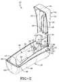
- FIG. 2is a perspective view of the dispenser housing of the present invention with the cover and intermediary member in an open position to allow for insertion of a refill unit.
- FIG. 3is a perspective view of the dispenser housing as in FIG. 2 showing the refill unit within the housing.
- FIG. 4is a perspective view of the cover and intermediary member of the dispenser housing.
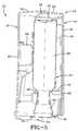
- FIG. 5is a section view of the dispenser housing of FIG. 1 , including a refill unit, where the cover is in an unactuated position.
- FIG. 6is a section view as in FIG. 5 , where the cover is in an actuated position.
- FIG. 7is a section view as in FIG. 5 , where the pivoting intermediary member and the cover are open to allow refilling of the dispenser.
- Dispenser 10includes a dispenser housing 12 having a backplate 14 , an intermediary member 16 , and a cover 18 .
- Intermediary member 16is pivotally secured to backplate 14 at a first end of backplate 14 .
- intermediary member 16is pivotally secured to backplate 14 adjacent a bottom end of housing 12
- cover 18is pivotally secured to intermediary member 16 adjacent the top end of dispenser housing 12 .
- Backplate 14 , intermediary member 16 , and cover 18define an inner cavity within dispenser 10 .
- Cover 18is adapted to pivot relative to intermediary member 16 , thereby acting as a push bar to actuate dispenser 10 .
- Intermediary member 16pivots relative to back late 14 so as to open housing 12 for refilling or replacing a refill unit therein.
- Backplate 14is adapted to be secured to a wall or other surface, and may be so secured by any attachment mechanism known in the art. In one or more embodiments, backplate 14 may be adapted to be secured within a shower or other bathroom surface.
- Backplate 14includes a back wall 20 , side walls 22 , a top wall 24 , and a bottom wall 26 .
- the side walls 22extend from opposing edges of back wall 20 , and are oriented generally perpendicular thereto.
- Top wall 24 and bottom wall 26extend from opposing edges of back wall 20 between side walls 22 .
- Bottom wall 26may include an opening or recess therein to facilitate dispensing of liquid or foam from dispenser 10 , as will be discussed in detail below.
- Backplate 14also includes a pair of journals 28 , one extending outwardly from each side wall 22 adjacent bottom wall 26 . Journals 28 are positioned coaxially on side walls 22 and define a pivot axis about which intermediary member 16 rotates.
- Backplate 14also includes projections 30 extending inwardly from back wall 20 .
- Projections 30are generally perpendicular to back wall 20 and are oriented substantially vertically within housing 12 . While a pair of parallel projections 30 are shown in the drawings, it is contemplated that other forms of projections 30 may be utilized. For example, a solid block-like projection may be provided having a width approximately equal to the space between projections 30 shown in the drawings.
- a retaining collar 32also extends from back wall 20 and is oriented generally perpendicular thereto. Retaining collar 32 includes a radiused recess on an inner edge thereof that is adapted to receive a refill unit and secure it within dispenser 10 .
- Intermediary member 16includes a body 34 that is arched in the transverse direction creating a radiused inner surface.
- Body 34includes an opening 36 therethrough to allow for actuation of the dispenser 10 , as will be discussed below.
- Ears 38are provided on opposing sides of body 34 adjacent to bottom wall 26 of backplate 14 .
- Ears 38include apertures 40 therethrough that are adapted to receive journals 28 of backplate 14 , thereby pivotally securing intermediary member 16 to backplate 14 .
- a retaining collar 42extends from the interior surface of body 34 , and is positioned opposite retaining collar 32 of backplate 14 when intermediary member 16 is in a closed position.
- Retaining collar 42includes a radiused recess on an interior edge thereof so that together with retaining collar 32 a generally circular opening is defined.
- a pair of slots 44are provided through body 34 of intermediary member 16 below retaining collar 42 to help to secure cover 18 to intermediary member 16 , as will become apparent from the description below.
- Intermediary member 16also includes journals 46 extending outwardly from opposing sides of body 34 adjacent to a top end thereof. Journals 46 are positioned coaxially, and define a cover pivot axis about which cover 18 rotates.
- Intermediary member 16may also include a latch 47 extending therefrom, which acts to secure the top end of intermediary member 16 to backplate 14 .
- a release barmay be provided in backplate 14 which, when pressed upward, causes latch 47 to disengage and allows dispenser 12 to be opened. Release bar may optionally be keyed so that only authorized personnel have access to the interior of dispenser 12 , as is well known in the art.
- Cover 18includes a front wall 48 , a top wall 50 , and a bottom wall 52 .
- Front wall 48is arched in the transverse direction, thereby creating a radiused outer surface.
- Bottom wall 52may include a dispensing opening 54 to facilitate the dispensation of liquid or foam from dispenser 10 .
- a projection 56extends inwardly from the inner surface of front wall 48 toward projections 30 on backplate 14 .
- Projection 56 of cover 18extends through opening 36 in intermediary member 16 .
- a pair of flexible arms 58may extend inwardly from the interior surface of front wall 48 to secure cover 18 to intermediary member 16 .
- the flexible arms 58extend through slots 44 in intermediary member 16 and may include latch members on the ends thereof to prevent cover 18 from being pulled away from intermediary member 16 .
- Cover 18also includes inwardly facing pivot apertures 60 on opposing sides of front wall 48 adjacent to top wall 50 . Pivot apertures 60 are adapted to receive journals 46 of intermediary member 16 , thereby pivotally
- a refill unit 62is positioned within dispenser 10 and includes a valve mechanism 64 and a product reservoir 66 .
- Valve mechanism 64may be any such valve mechanism known to those skilled in the art, and may be adapted to dispense a liquid or a foam product.
- valve mechanism 64may be a foam producing valve such as the EZi® Foamer manufactured and sold by Rexam Airspray, Inc.
- Product reservoir 66may be flexible and resilient, thus allowing it to be compressed and providing it with the capability of returning to its original form. Sufficient space is provided around product reservoir 66 within housing 12 to allow it to flex or expand in various directions when compressed.
- sufficient spaceis provided within housing 12 to allow product reservoir to expand or flex in the lateral direction (perpendicular to the direction of compression) by at least 5% of it's original size, in other embodiments at least 10%, and in still other embodiments at least 15%.
- Product reservoir 66includes a shoulder 68 at its lower edge that is adapted to rest on retaining collar 32 and retaining collar 42 to support refill unit 62 within dispenser 10 .
- Valve mechanism 64may be provided with a circumferential flange 70 at its extreme end, flange 70 acting to position and secure valve mechanism 64 within dispenser 10 .
- cover 18may be pressed toward backplate 14 to actuate dispenser 10 .
- Projection 56extends through opening 36 when cover 18 is pressed, thereby engaging and compressing product reservoir 66 to force product therein through valve mechanism 64 .
- Projections 30 on back wall 20 of backplate 14maintain product reservoir 66 in a displaced position relative to back wall 14 of housing 12 , thereby maintaining a sufficient amount of space around product reservoir 66 to allow it to flex. This ability of product reservoir 66 to flex when compressed improves the performance of valve mechanism 64 .
- valve mechanism 64When product reservoir 66 is compressed by projection 56 , a volume of liquid or foam is caused to be dispensed from valve mechanism 64 .
- the liquid or foampasses through dispensing opening 54 of cover 18 , and may be retrieved by the person actuating dispenser 10 .
- the natural resiliency of product reservoir 66causes it to return to its original shape, thereby forcing cover 18 into an unactuated position by acting upon projection 56 .
- the expansion of product reservoir 66 after compressionalso creates a vacuum therein, which draws air in through valve mechanism 64 .
- This air intake, or “suck back”causes any product remaining in the valve mechanism 64 to be drawn back into product reservoir 66 , and also provides air within valve mechanism 64 to be used to generate foam product, where necessary.
- This air intake functionmay also be accomplished by one-way valves in the product dispenser. Dispenser 10 is then in a condition to be actuated again.
- cover 18pivots relative to intermediary member 16 and backplate 14 by virtue of journals 46 and pivot apertures 60 , both positioned adjacent top wall 50 of cover 18 .
- This arrangementallows a user to press the lower portion of cover 18 to actuate dispenser 10 and cause liquid or foam to be dispensed.
- cover dispensing opening 54it is possible for a person to press cover 18 to actuate dispenser 10 and cover dispensing opening 54 to catch the liquid or foam dispensed with one hand.
- housing 12may be opened by pressing latch 47 and pivoting intermediary member 16 and cover 18 relative to backplate 14 .
- Intermediary member 16pivots by virtue of journals 28 and apertures 40 in ears 38 , which connect it to backplate 14 adjacent to bottom wall 26 .
- This arrangementallows housing 12 to be opened by pivoting intermediary member 16 and cover 18 downward, as shown in FIG. 7 .
- the refill unit 62may be replaced without worrying that part of the housing may swing close.
Landscapes
- Engineering & Computer Science (AREA)
- Mechanical Engineering (AREA)
- Health & Medical Sciences (AREA)
- Public Health (AREA)
- Containers And Packaging Bodies Having A Special Means To Remove Contents (AREA)
- Closures For Containers (AREA)
Abstract
Description
Claims (10)
Priority Applications (18)
| Application Number | Priority Date | Filing Date | Title |
|---|---|---|---|
| US12/399,426US8387832B2 (en) | 2009-03-06 | 2009-03-06 | Dispenser housing |
| EP13188833.1AEP2687137B1 (en) | 2009-03-06 | 2010-03-03 | Dispenser housing |
| PT131888331TPT2687137E (en) | 2009-03-06 | 2010-03-03 | DISTRIBUTOR SUPPORT |
| PT101553634TPT2225988E (en) | 2009-03-06 | 2010-03-03 | DISTRIBUTOR SUPPORT |
| ES10155363.4TES2443303T3 (en) | 2009-03-06 | 2010-03-03 | Dispenser housing |
| DK13188833.1TDK2687137T3 (en) | 2009-03-06 | 2010-03-03 | dispenser |
| CA2695292ACA2695292A1 (en) | 2009-03-06 | 2010-03-03 | Dispenser housing |
| DK10155363.4TDK2225988T3 (en) | 2009-03-06 | 2010-03-03 | dispenser |
| ES13188833.1TES2532723T3 (en) | 2009-03-06 | 2010-03-03 | Dispenser housing |
| EP10155363.4AEP2225988B1 (en) | 2009-03-06 | 2010-03-03 | Dispenser housing |
| CN201010126895.5ACN101823596B (en) | 2009-03-06 | 2010-03-04 | Dispenser housing |
| TW099106328ATW201032767A (en) | 2009-03-06 | 2010-03-04 | Dispenser housing |
| AU2010200843AAU2010200843B2 (en) | 2009-03-06 | 2010-03-05 | Dispenser housing |
| JP2010048802AJP5507293B2 (en) | 2009-03-06 | 2010-03-05 | Dispenser |
| MYPI2010000975MY152763A (en) | 2009-03-06 | 2010-03-05 | Dispenser housing |
| BRPI1000540-4ABRPI1000540A2 (en) | 2009-03-06 | 2010-03-05 | dispenser and dispenser housing |
| KR1020100019642AKR20100100683A (en) | 2009-03-06 | 2010-03-05 | Dispenser housing |
| HK10108920.6AHK1142507B (en) | 2009-03-06 | 2010-09-20 | Dispenser housing |
Applications Claiming Priority (1)
| Application Number | Priority Date | Filing Date | Title |
|---|---|---|---|
| US12/399,426US8387832B2 (en) | 2009-03-06 | 2009-03-06 | Dispenser housing |
Publications (2)
| Publication Number | Publication Date |
|---|---|
| US20100224651A1 US20100224651A1 (en) | 2010-09-09 |
| US8387832B2true US8387832B2 (en) | 2013-03-05 |
Family
ID=42288837
Family Applications (1)
| Application Number | Title | Priority Date | Filing Date |
|---|---|---|---|
| US12/399,426Expired - Fee RelatedUS8387832B2 (en) | 2009-03-06 | 2009-03-06 | Dispenser housing |
Country Status (13)
| Country | Link |
|---|---|
| US (1) | US8387832B2 (en) |
| EP (2) | EP2687137B1 (en) |
| JP (1) | JP5507293B2 (en) |
| KR (1) | KR20100100683A (en) |
| CN (1) | CN101823596B (en) |
| AU (1) | AU2010200843B2 (en) |
| BR (1) | BRPI1000540A2 (en) |
| CA (1) | CA2695292A1 (en) |
| DK (2) | DK2225988T3 (en) |
| ES (2) | ES2532723T3 (en) |
| MY (1) | MY152763A (en) |
| PT (2) | PT2225988E (en) |
| TW (1) | TW201032767A (en) |
Cited By (10)
| Publication number | Priority date | Publication date | Assignee | Title |
|---|---|---|---|---|
| US20150053720A1 (en)* | 2013-08-23 | 2015-02-26 | Gojo Industries, Inc. | Dispenser having top loading and unloading refill units |
| US20150197377A1 (en)* | 2014-01-12 | 2015-07-16 | Sodastream Industries Ltd. | Safety door for a gas cylinder |
| USD768406S1 (en) | 2015-09-15 | 2016-10-11 | Georgia-Pacific Consumer Products Lp | Dispenser |
| USD768407S1 (en) | 2015-09-15 | 2016-10-11 | Georgia-Pacific Consumer Products Lp | Dispenser |
| USD768405S1 (en) | 2015-09-15 | 2016-10-11 | Georgia-Pacific Consumer Products Lp | Dispenser |
| US20170245697A1 (en)* | 2016-02-26 | 2017-08-31 | Gojo Industries, Inc. | Dispenser with nozzle aperture guard |
| US20180118554A1 (en)* | 2016-11-01 | 2018-05-03 | Sone Llc | Apparatus for dispensing viscous liquids from a container |
| US20180146828A1 (en)* | 2016-11-29 | 2018-05-31 | Gojo Industries, Inc. | Manually activated dispensers for squeezable bottles |
| US10376106B2 (en)* | 2015-04-07 | 2019-08-13 | Vi-Jon, Inc. | Dispenser assembly |
| US10561282B2 (en) | 2017-12-21 | 2020-02-18 | Speakman Company | Ligature-resistant dispenser |
Families Citing this family (31)
| Publication number | Priority date | Publication date | Assignee | Title |
|---|---|---|---|---|
| DE202010009176U1 (en)* | 2010-06-17 | 2011-12-19 | Ada Cosmetic Gmbh | Wanddosierspender |
| US8678236B2 (en)* | 2012-07-03 | 2014-03-25 | Rich Products Corporation | Simple serve topping dispenser |
| US9518691B2 (en)* | 2013-03-15 | 2016-12-13 | The Coca-Cola Company | Efficiently and easily opening and closing a canister valve |
| JP6180233B2 (en)* | 2013-08-23 | 2017-08-16 | 三笠産業株式会社 | Storage container for dispensing |
| US9974416B2 (en) | 2013-12-20 | 2018-05-22 | Toaster Labs, Inc. | Automatic heated fluid dispenser |
| US9801505B2 (en)* | 2013-12-20 | 2017-10-31 | Toaster Labs, Inc. | Automatic fluid dispenser |
| US10144032B2 (en) | 2013-12-20 | 2018-12-04 | Toaster Labs, Inc. | Inductively heatable fluid reservoir |
| US10098510B2 (en) | 2013-12-20 | 2018-10-16 | Toaster Loabs, Inc. | Pneumatically driven fluid dispenser |
| USD757459S1 (en)* | 2014-04-25 | 2016-05-31 | Hansgrohe Se | Soap dispenser |
| USD767301S1 (en)* | 2014-10-07 | 2016-09-27 | Daansen U.S.A. Inc. | Dispenser |
| EP3212053B1 (en)* | 2014-10-31 | 2019-10-23 | Toaster Labs, Inc. | Automatic heated fluid dispenser |
| CA159265S (en)* | 2014-11-03 | 2016-04-05 | Blp Internat Inc | Liquid dispenser |
| AU362368S (en)* | 2014-12-19 | 2015-06-18 | Sca Hygiene Prod Ab | Tissue dispenser |
| US9643200B2 (en)* | 2014-12-19 | 2017-05-09 | Richard A. Belanger | Squeeze container liquid extrusion tool |
| USD766008S1 (en)* | 2014-12-22 | 2016-09-13 | Richard L. Ernst | Soap and gel dispenser |
| US20160250887A1 (en)* | 2015-02-27 | 2016-09-01 | Gojo Industries, Inc. | Hygiene system for displaying a display medium |
| USD773849S1 (en)* | 2015-03-13 | 2016-12-13 | Buckeye International, Inc. | Dispenser for dispensing a cleaning solution |
| USD781613S1 (en)* | 2015-04-09 | 2017-03-21 | Vi-Jon, Inc. | Dispenser handle |
| USD775852S1 (en)* | 2015-05-21 | 2017-01-10 | Gregory L. Indruk | Dispenser |
| USD787856S1 (en)* | 2015-12-09 | 2017-05-30 | Susan K. Okuno-Jones | Wall mounted dual dispenser |
| USD831377S1 (en) | 2017-02-03 | 2018-10-23 | Rubbermaid Commercial Products, Llc | Soap dispenser |
| EP3585225B1 (en)* | 2017-02-22 | 2021-07-07 | GOJO Industries, Inc. | Dispensers, refill units and pumps having vacuum actuated antidrip mechanisms |
| US10743633B2 (en)* | 2017-03-17 | 2020-08-18 | Polder Products, Llc | Dual function hair styling tool holder |
| IT201900013149A1 (en)* | 2019-07-29 | 2021-01-29 | La Bottega Dellalbergo S P A | DISPENSER GROUP FOR LIQUID PRODUCTS. |
| USD981132S1 (en)* | 2019-10-02 | 2023-03-21 | Bradley Corporation | Towel dispenser |
| USD927218S1 (en)* | 2019-10-02 | 2021-08-10 | Bradley Corporation | Toilet paper dispenser |
| USD936998S1 (en)* | 2019-10-02 | 2021-11-30 | Bradley Corporation | Towel dispenser |
| USD944559S1 (en)* | 2020-11-11 | 2022-03-01 | Ningbo SKL International Co., LTD | Liquid dispenser |
| USD979284S1 (en) | 2021-01-08 | 2023-02-28 | Wella International Operations Switzerland Sàrl | Fluid dispenser covering |
| KR102797562B1 (en)* | 2021-12-22 | 2025-04-18 | 김석 | Supplementary device For Spray-Type Whipped Cream Dispenser |
| US11772121B1 (en)* | 2023-02-24 | 2023-10-03 | My Sweet Petunia, Inc. | Applicators and accessories for dispensing glue and other materials |
Citations (24)
| Publication number | Priority date | Publication date | Assignee | Title |
|---|---|---|---|---|
| US1306830A (en)* | 1919-06-17 | Surface-coating apparatus | ||
| GB1197918A (en) | 1966-08-30 | 1970-07-08 | Cornelius Bushnell Watson Jr | Container-Dispenser for Collapsible Tubes |
| FR2134935A5 (en) | 1971-04-21 | 1972-12-08 | Rapp Marcel | |
| US3926347A (en) | 1974-07-10 | 1975-12-16 | Jaclo Inc | Flowable material dispenser with resilient container |
| US4324348A (en) | 1980-01-18 | 1982-04-13 | Minnetonka, Inc. | Dispenser for dispensing liquid from a replaceable container |
| US4349131A (en)* | 1979-05-10 | 1982-09-14 | Europtool Trust | Apparatus for dosing and forming soap foam |
| US4463876A (en) | 1980-01-24 | 1984-08-07 | Npi New Products Investment Ab | Measuring device |
| US4722457A (en) | 1986-09-05 | 1988-02-02 | Fibre Glass-Evercoat Company, Inc. | Dispensing device |
| US4932562A (en) | 1988-04-29 | 1990-06-12 | Triparte, Ltd. | Liquid dispensing system |
| US5105984A (en) | 1990-06-27 | 1992-04-21 | Kazimir Charles E | Paste tube dispenser and method for making same |
| US5431304A (en) | 1994-01-18 | 1995-07-11 | Gentile; Aliseo | Liquid and particulate product dispenser |
| EP0787457A2 (en) | 1993-03-19 | 1997-08-06 | Inpaco Corporation | Liquid dispensing system |
| US5897030A (en) | 1997-04-10 | 1999-04-27 | Stangle; John A. | Toothpaste dispenser |
| US6152330A (en) | 1999-02-11 | 2000-11-28 | Chester Labs, Inc. | Hinged dispenser housing |
| WO2001028397A1 (en) | 1999-10-19 | 2001-04-26 | Bentfield Europe B.V. | Dispenser assembly for liquids |
| US6305580B1 (en)* | 2000-12-26 | 2001-10-23 | Sin-Hsiung Chen | Press-type perfume sprayer |
| US6695174B2 (en) | 2000-08-08 | 2004-02-24 | Scandinavian Amenities A/S | Soap dispenser |
| US7048152B2 (en) | 2003-03-05 | 2006-05-23 | Brightwell Dispensers Limited | Soap dispensing device |
| US7066356B2 (en)* | 2002-08-15 | 2006-06-27 | Ecolab Inc. | Foam soap dispenser for push operation |
| US20070137643A1 (en)* | 2004-02-06 | 2007-06-21 | Bonney Stanley G | Fluid dispenser |
| US7278554B2 (en) | 2004-05-10 | 2007-10-09 | Chester Labs, Inc. | Hinged dispenser housing and adaptor |
| US7281643B2 (en)* | 2005-06-14 | 2007-10-16 | Po-Hui Lin | Automatic soap dispenser structure |
| US20080083786A1 (en) | 2006-10-06 | 2008-04-10 | Proandre, S.L. | Fluid soap dispenser and fluid soap bottle associated to the dispenser |
| US20090212073A1 (en)* | 2005-05-03 | 2009-08-27 | Haworth Brian D | Soap dispensing apparatus |
Family Cites Families (9)
| Publication number | Priority date | Publication date | Assignee | Title |
|---|---|---|---|---|
| US4634022A (en)* | 1985-05-28 | 1987-01-06 | Halloran P Joseph O | Fixture for bag-type liquid dispenser |
| US5377871A (en)* | 1993-01-04 | 1995-01-03 | Marlingford Holdings Limited | Dispenser having roller for dispensing fluid from a collapsible bag |
| CN1038733C (en)* | 1993-03-09 | 1998-06-17 | 彼得·N·汤姆 | High-viscosity pump system for dosing boxes |
| US6877642B1 (en)* | 2000-01-04 | 2005-04-12 | Joseph S. Kanfer | Wall-mounted dispenser for liquids |
| US6581804B1 (en)* | 2002-01-11 | 2003-06-24 | Joseph S. Kanfer | Holder for aerosol dispenser |
| US7086567B1 (en)* | 2002-07-25 | 2006-08-08 | Joseph S. Kanfer | Wall-mounted dispenser assembly with transparent window |
| JP4121892B2 (en)* | 2003-05-01 | 2008-07-23 | サラヤ株式会社 | Dispenser |
| JP2007151646A (en)* | 2005-12-01 | 2007-06-21 | Shinko Chemical Co Ltd | Injection adapter of medicinal solution container |
| US20080008376A1 (en)* | 2006-07-07 | 2008-01-10 | Lockheed Martin Corporation | Detection and identification of postal indicia |
- 2009
- 2009-03-06USUS12/399,426patent/US8387832B2/ennot_activeExpired - Fee Related
- 2010
- 2010-03-03PTPT101553634Tpatent/PT2225988E/enunknown
- 2010-03-03ESES13188833.1Tpatent/ES2532723T3/enactiveActive
- 2010-03-03DKDK10155363.4Tpatent/DK2225988T3/enactive
- 2010-03-03DKDK13188833.1Tpatent/DK2687137T3/enactive
- 2010-03-03ESES10155363.4Tpatent/ES2443303T3/enactiveActive
- 2010-03-03EPEP13188833.1Apatent/EP2687137B1/ennot_activeNot-in-force
- 2010-03-03PTPT131888331Tpatent/PT2687137E/enunknown
- 2010-03-03EPEP10155363.4Apatent/EP2225988B1/ennot_activeNot-in-force
- 2010-03-03CACA2695292Apatent/CA2695292A1/ennot_activeAbandoned
- 2010-03-04TWTW099106328Apatent/TW201032767A/enunknown
- 2010-03-04CNCN201010126895.5Apatent/CN101823596B/ennot_activeExpired - Fee Related
- 2010-03-05MYMYPI2010000975patent/MY152763A/enunknown
- 2010-03-05JPJP2010048802Apatent/JP5507293B2/ennot_activeExpired - Fee Related
- 2010-03-05AUAU2010200843Apatent/AU2010200843B2/ennot_activeCeased
- 2010-03-05KRKR1020100019642Apatent/KR20100100683A/ennot_activeWithdrawn
- 2010-03-05BRBRPI1000540-4Apatent/BRPI1000540A2/ennot_activeIP Right Cessation
Patent Citations (24)
| Publication number | Priority date | Publication date | Assignee | Title |
|---|---|---|---|---|
| US1306830A (en)* | 1919-06-17 | Surface-coating apparatus | ||
| GB1197918A (en) | 1966-08-30 | 1970-07-08 | Cornelius Bushnell Watson Jr | Container-Dispenser for Collapsible Tubes |
| FR2134935A5 (en) | 1971-04-21 | 1972-12-08 | Rapp Marcel | |
| US3926347A (en) | 1974-07-10 | 1975-12-16 | Jaclo Inc | Flowable material dispenser with resilient container |
| US4349131A (en)* | 1979-05-10 | 1982-09-14 | Europtool Trust | Apparatus for dosing and forming soap foam |
| US4324348A (en) | 1980-01-18 | 1982-04-13 | Minnetonka, Inc. | Dispenser for dispensing liquid from a replaceable container |
| US4463876A (en) | 1980-01-24 | 1984-08-07 | Npi New Products Investment Ab | Measuring device |
| US4722457A (en) | 1986-09-05 | 1988-02-02 | Fibre Glass-Evercoat Company, Inc. | Dispensing device |
| US4932562A (en) | 1988-04-29 | 1990-06-12 | Triparte, Ltd. | Liquid dispensing system |
| US5105984A (en) | 1990-06-27 | 1992-04-21 | Kazimir Charles E | Paste tube dispenser and method for making same |
| EP0787457A2 (en) | 1993-03-19 | 1997-08-06 | Inpaco Corporation | Liquid dispensing system |
| US5431304A (en) | 1994-01-18 | 1995-07-11 | Gentile; Aliseo | Liquid and particulate product dispenser |
| US5897030A (en) | 1997-04-10 | 1999-04-27 | Stangle; John A. | Toothpaste dispenser |
| US6152330A (en) | 1999-02-11 | 2000-11-28 | Chester Labs, Inc. | Hinged dispenser housing |
| WO2001028397A1 (en) | 1999-10-19 | 2001-04-26 | Bentfield Europe B.V. | Dispenser assembly for liquids |
| US6695174B2 (en) | 2000-08-08 | 2004-02-24 | Scandinavian Amenities A/S | Soap dispenser |
| US6305580B1 (en)* | 2000-12-26 | 2001-10-23 | Sin-Hsiung Chen | Press-type perfume sprayer |
| US7066356B2 (en)* | 2002-08-15 | 2006-06-27 | Ecolab Inc. | Foam soap dispenser for push operation |
| US7048152B2 (en) | 2003-03-05 | 2006-05-23 | Brightwell Dispensers Limited | Soap dispensing device |
| US20070137643A1 (en)* | 2004-02-06 | 2007-06-21 | Bonney Stanley G | Fluid dispenser |
| US7278554B2 (en) | 2004-05-10 | 2007-10-09 | Chester Labs, Inc. | Hinged dispenser housing and adaptor |
| US20090212073A1 (en)* | 2005-05-03 | 2009-08-27 | Haworth Brian D | Soap dispensing apparatus |
| US7281643B2 (en)* | 2005-06-14 | 2007-10-16 | Po-Hui Lin | Automatic soap dispenser structure |
| US20080083786A1 (en) | 2006-10-06 | 2008-04-10 | Proandre, S.L. | Fluid soap dispenser and fluid soap bottle associated to the dispenser |
Cited By (13)
| Publication number | Priority date | Publication date | Assignee | Title |
|---|---|---|---|---|
| US20150053720A1 (en)* | 2013-08-23 | 2015-02-26 | Gojo Industries, Inc. | Dispenser having top loading and unloading refill units |
| US20150197377A1 (en)* | 2014-01-12 | 2015-07-16 | Sodastream Industries Ltd. | Safety door for a gas cylinder |
| US10376106B2 (en)* | 2015-04-07 | 2019-08-13 | Vi-Jon, Inc. | Dispenser assembly |
| USD768407S1 (en) | 2015-09-15 | 2016-10-11 | Georgia-Pacific Consumer Products Lp | Dispenser |
| USD768405S1 (en) | 2015-09-15 | 2016-10-11 | Georgia-Pacific Consumer Products Lp | Dispenser |
| USD768406S1 (en) | 2015-09-15 | 2016-10-11 | Georgia-Pacific Consumer Products Lp | Dispenser |
| US20170245697A1 (en)* | 2016-02-26 | 2017-08-31 | Gojo Industries, Inc. | Dispenser with nozzle aperture guard |
| US10485384B2 (en)* | 2016-02-26 | 2019-11-26 | Gojo Industries, Inc. | Dispenser with nozzle aperture guard |
| US20180118554A1 (en)* | 2016-11-01 | 2018-05-03 | Sone Llc | Apparatus for dispensing viscous liquids from a container |
| US20180146828A1 (en)* | 2016-11-29 | 2018-05-31 | Gojo Industries, Inc. | Manually activated dispensers for squeezable bottles |
| US10321791B2 (en) | 2016-11-29 | 2019-06-18 | Gojo Industries, Inc. | Manually activated dispensers for squeezable bottles |
| US10561282B2 (en) | 2017-12-21 | 2020-02-18 | Speakman Company | Ligature-resistant dispenser |
| US11045052B2 (en) | 2017-12-21 | 2021-06-29 | Speakman Company | Ligature-resistant dispenser |
Also Published As
| Publication number | Publication date |
|---|---|
| US20100224651A1 (en) | 2010-09-09 |
| ES2443303T3 (en) | 2014-02-18 |
| JP5507293B2 (en) | 2014-05-28 |
| CN101823596A (en) | 2010-09-08 |
| ES2532723T3 (en) | 2015-03-31 |
| MY152763A (en) | 2014-11-28 |
| CA2695292A1 (en) | 2010-09-06 |
| AU2010200843B2 (en) | 2015-10-22 |
| JP2010208694A (en) | 2010-09-24 |
| AU2010200843A1 (en) | 2010-09-23 |
| EP2687137B1 (en) | 2015-02-11 |
| EP2687137A1 (en) | 2014-01-22 |
| KR20100100683A (en) | 2010-09-15 |
| PT2225988E (en) | 2014-02-25 |
| CN101823596B (en) | 2014-02-19 |
| TW201032767A (en) | 2010-09-16 |
| HK1142507A1 (en) | 2010-12-10 |
| DK2225988T3 (en) | 2014-01-20 |
| BRPI1000540A2 (en) | 2011-03-22 |
| DK2687137T3 (en) | 2015-05-11 |
| PT2687137E (en) | 2015-05-15 |
| EP2225988B1 (en) | 2013-12-18 |
| EP2225988A1 (en) | 2010-09-08 |
Similar Documents
| Publication | Publication Date | Title |
|---|---|---|
| US8387832B2 (en) | Dispenser housing | |
| US8640926B2 (en) | Dispenser with flexible cover | |
| JP2010208694A5 (en) | ||
| EP0663175B1 (en) | Push-type soap dispenser | |
| AU778493B2 (en) | Wall-mounted dispenser for liquids | |
| US8387834B2 (en) | Dispenser with collapsible dispensing tube | |
| US8807398B2 (en) | Dispenser and liquid container | |
| EP1595483A2 (en) | Hinged dispenser housing and adaptor | |
| HK1142507B (en) | Dispenser housing | |
| WO2015070198A1 (en) | Dispenser reservoir release mechanism | |
| HK1155628A (en) | Dispenser with collapsible dispensing tube |
Legal Events
| Date | Code | Title | Description |
|---|---|---|---|
| AS | Assignment | Owner name:GOJO INDUSTRIES, INC., OHIO Free format text:ASSIGNMENT OF ASSIGNORS INTEREST;ASSIGNOR:ZLATIC, DOUG;REEL/FRAME:022358/0258 Effective date:20090304 | |
| AS | Assignment | Owner name:PNC BANK, NATIONAL ASSOCIATION, PENNSYLVANIA Free format text:SECURITY AGREEMENT;ASSIGNOR:GOJO INDUSTRIES, INC.;REEL/FRAME:025454/0001 Effective date:20101029 | |
| AS | Assignment | Owner name:STEEL CITY CAPITAL FUNDING, A DIVISION OF PNC BANK Free format text:SECURITY AGREEMENT;ASSIGNOR:GOJO INDUSTRIES, INC.;REEL/FRAME:025495/0678 Effective date:20101029 | |
| AS | Assignment | Owner name:GOJO INDUSTRIES, INC., OHIO Free format text:RELEASE BY SECURED PARTY;ASSIGNOR:STEEL CITY CAPITAL FUNDING, A DIVISION OF PNC BANK, NATIONAL ASSOCIATION;REEL/FRAME:028575/0804 Effective date:20120713 | |
| STCF | Information on status: patent grant | Free format text:PATENTED CASE | |
| FPAY | Fee payment | Year of fee payment:4 | |
| MAFP | Maintenance fee payment | Free format text:PAYMENT OF MAINTENANCE FEE, 8TH YEAR, LARGE ENTITY (ORIGINAL EVENT CODE: M1552); ENTITY STATUS OF PATENT OWNER: LARGE ENTITY Year of fee payment:8 | |
| AS | Assignment | Owner name:PNC BANK, NATIONAL ASSOCIATION, PENNSYLVANIA Free format text:SECURITY INTEREST;ASSIGNOR:GOJO INDUSTRIES, INC.;REEL/FRAME:065369/0253 Effective date:20231026 | |
| AS | Assignment | Owner name:SILVER POINT FINANCE, LLC, AS COLLATERAL AGENT, CONNECTICUT Free format text:SECURITY INTEREST;ASSIGNOR:GOJO INDUSTRIES, INC.;REEL/FRAME:065382/0587 Effective date:20231026 | |
| FEPP | Fee payment procedure | Free format text:MAINTENANCE FEE REMINDER MAILED (ORIGINAL EVENT CODE: REM.); ENTITY STATUS OF PATENT OWNER: LARGE ENTITY | |
| LAPS | Lapse for failure to pay maintenance fees | Free format text:PATENT EXPIRED FOR FAILURE TO PAY MAINTENANCE FEES (ORIGINAL EVENT CODE: EXP.); ENTITY STATUS OF PATENT OWNER: LARGE ENTITY | |
| STCH | Information on status: patent discontinuation | Free format text:PATENT EXPIRED DUE TO NONPAYMENT OF MAINTENANCE FEES UNDER 37 CFR 1.362 | |
| FP | Lapsed due to failure to pay maintenance fee | Effective date:20250305 |