US8387441B2 - Injector flow measurement for fuel cell applications - Google Patents
Injector flow measurement for fuel cell applicationsDownload PDFInfo
- Publication number
- US8387441B2 US8387441B2US12/636,276US63627609AUS8387441B2US 8387441 B2US8387441 B2US 8387441B2US 63627609 AUS63627609 AUS 63627609AUS 8387441 B2US8387441 B2US 8387441B2
- Authority
- US
- United States
- Prior art keywords
- injector
- fuel
- pressure
- determining
- anode
- Prior art date
- Legal status (The legal status is an assumption and is not a legal conclusion. Google has not performed a legal analysis and makes no representation as to the accuracy of the status listed.)
- Active, expires
Links
Images

Classifications
- G—PHYSICS
- G01—MEASURING; TESTING
- G01M—TESTING STATIC OR DYNAMIC BALANCE OF MACHINES OR STRUCTURES; TESTING OF STRUCTURES OR APPARATUS, NOT OTHERWISE PROVIDED FOR
- G01M3/00—Investigating fluid-tightness of structures
- G01M3/02—Investigating fluid-tightness of structures by using fluid or vacuum
- G01M3/26—Investigating fluid-tightness of structures by using fluid or vacuum by measuring rate of loss or gain of fluid, e.g. by pressure-responsive devices, by flow detectors
- G—PHYSICS
- G01—MEASURING; TESTING
- G01F—MEASURING VOLUME, VOLUME FLOW, MASS FLOW OR LIQUID LEVEL; METERING BY VOLUME
- G01F1/00—Measuring the volume flow or mass flow of fluid or fluent solid material wherein the fluid passes through a meter in a continuous flow
- G01F1/05—Measuring the volume flow or mass flow of fluid or fluent solid material wherein the fluid passes through a meter in a continuous flow by using mechanical effects
- G01F1/34—Measuring the volume flow or mass flow of fluid or fluent solid material wherein the fluid passes through a meter in a continuous flow by using mechanical effects by measuring pressure or differential pressure
- G01F1/36—Measuring the volume flow or mass flow of fluid or fluent solid material wherein the fluid passes through a meter in a continuous flow by using mechanical effects by measuring pressure or differential pressure the pressure or differential pressure being created by the use of flow constriction
- G01F1/363—Measuring the volume flow or mass flow of fluid or fluent solid material wherein the fluid passes through a meter in a continuous flow by using mechanical effects by measuring pressure or differential pressure the pressure or differential pressure being created by the use of flow constriction with electrical or electro-mechanical indication
- G—PHYSICS
- G01—MEASURING; TESTING
- G01F—MEASURING VOLUME, VOLUME FLOW, MASS FLOW OR LIQUID LEVEL; METERING BY VOLUME
- G01F1/00—Measuring the volume flow or mass flow of fluid or fluent solid material wherein the fluid passes through a meter in a continuous flow
- G01F1/05—Measuring the volume flow or mass flow of fluid or fluent solid material wherein the fluid passes through a meter in a continuous flow by using mechanical effects
- G01F1/34—Measuring the volume flow or mass flow of fluid or fluent solid material wherein the fluid passes through a meter in a continuous flow by using mechanical effects by measuring pressure or differential pressure
- G01F1/36—Measuring the volume flow or mass flow of fluid or fluent solid material wherein the fluid passes through a meter in a continuous flow by using mechanical effects by measuring pressure or differential pressure the pressure or differential pressure being created by the use of flow constriction
- G01F1/40—Details of construction of the flow constriction devices
- G—PHYSICS
- G01—MEASURING; TESTING
- G01F—MEASURING VOLUME, VOLUME FLOW, MASS FLOW OR LIQUID LEVEL; METERING BY VOLUME
- G01F1/00—Measuring the volume flow or mass flow of fluid or fluent solid material wherein the fluid passes through a meter in a continuous flow
- G01F1/72—Devices for measuring pulsing fluid flows
- H—ELECTRICITY
- H01—ELECTRIC ELEMENTS
- H01M—PROCESSES OR MEANS, e.g. BATTERIES, FOR THE DIRECT CONVERSION OF CHEMICAL ENERGY INTO ELECTRICAL ENERGY
- H01M8/00—Fuel cells; Manufacture thereof
- H01M8/04—Auxiliary arrangements, e.g. for control of pressure or for circulation of fluids
- H01M8/04298—Processes for controlling fuel cells or fuel cell systems
- H01M8/04313—Processes for controlling fuel cells or fuel cell systems characterised by the detection or assessment of variables; characterised by the detection or assessment of failure or abnormal function
- H01M8/0438—Pressure; Ambient pressure; Flow
- H01M8/04388—Pressure; Ambient pressure; Flow of anode reactants at the inlet or inside the fuel cell
- H—ELECTRICITY
- H01—ELECTRIC ELEMENTS
- H01M—PROCESSES OR MEANS, e.g. BATTERIES, FOR THE DIRECT CONVERSION OF CHEMICAL ENERGY INTO ELECTRICAL ENERGY
- H01M8/00—Fuel cells; Manufacture thereof
- H01M8/04—Auxiliary arrangements, e.g. for control of pressure or for circulation of fluids
- H01M8/04298—Processes for controlling fuel cells or fuel cell systems
- H01M8/04694—Processes for controlling fuel cells or fuel cell systems characterised by variables to be controlled
- H01M8/04746—Pressure; Flow
- H01M8/04753—Pressure; Flow of fuel cell reactants
- H—ELECTRICITY
- H01—ELECTRIC ELEMENTS
- H01M—PROCESSES OR MEANS, e.g. BATTERIES, FOR THE DIRECT CONVERSION OF CHEMICAL ENERGY INTO ELECTRICAL ENERGY
- H01M8/00—Fuel cells; Manufacture thereof
- H01M8/10—Fuel cells with solid electrolytes
- H01M2008/1095—Fuel cells with polymeric electrolytes
- Y—GENERAL TAGGING OF NEW TECHNOLOGICAL DEVELOPMENTS; GENERAL TAGGING OF CROSS-SECTIONAL TECHNOLOGIES SPANNING OVER SEVERAL SECTIONS OF THE IPC; TECHNICAL SUBJECTS COVERED BY FORMER USPC CROSS-REFERENCE ART COLLECTIONS [XRACs] AND DIGESTS
- Y02—TECHNOLOGIES OR APPLICATIONS FOR MITIGATION OR ADAPTATION AGAINST CLIMATE CHANGE
- Y02E—REDUCTION OF GREENHOUSE GAS [GHG] EMISSIONS, RELATED TO ENERGY GENERATION, TRANSMISSION OR DISTRIBUTION
- Y02E60/00—Enabling technologies; Technologies with a potential or indirect contribution to GHG emissions mitigation
- Y02E60/30—Hydrogen technology
- Y02E60/50—Fuel cells
Definitions
- This inventionrelates generally to a method for determining a metered flow of hydrogen fuel to a fuel cell stack and, more particularly, to a method for determining a metered flow of hydrogen fuel through a pulsed injector to a fuel cell stack that uses anode sub-system pressure before the pulsed injection and after the pulsed injection.
- a hydrogen fuel cellis an electro-chemical device that includes an anode and a cathode with an electrolyte therebetween.
- the anodereceives hydrogen gas and the cathode receives oxygen or air.
- the hydrogen gasis dissociated at the anode catalyst to generate free protons and electrons.
- the protonspass through the electrolyte to the cathode.
- the protonsreact with the oxygen and the electrons at the cathode catalyst to generate water.
- the electrons from the anodecannot pass through the electrolyte, and thus are directed through a load to perform work before being sent to the cathode.
- PEMFCProton exchange membrane fuel cells
- the PEMFCgenerally includes a solid polymer electrolyte proton conducting membrane, such as a perfluorosulfonic acid membrane.
- the anode and cathodetypically include finely divided catalytic particles, usually platinum (Pt), supported on carbon particles and mixed with an ionomer.
- Ptplatinum
- the catalytic mixtureis deposited on opposing sides of the membrane.
- the combination of the anode catalytic mixture, the cathode catalytic mixture and the membranedefine a membrane electrode assembly (MEA).
- MEAsare relatively expensive to manufacture and require certain conditions for effective operation.
- a typical fuel cell stack for a vehiclemay have two hundred or more stacked fuel cells.
- the fuel cell stackreceives a cathode input gas, typically a flow of air forced through the stack by a compressor. Not all of the oxygen is consumed by the stack and some of the air is output as a cathode exhaust gas that may include water as a stack by-product.
- the fuel cell stackalso receives an anode hydrogen input gas that flows into the anode side of the stack.
- a fuel cell stackincludes a series of bipolar plates positioned between the several MEAs in the stack, where the bipolar plates and the MEAs are positioned between two end plates.
- the bipolar platesinclude an anode side and a cathode side for adjacent fuel cells in the stack.
- Anode gas flow channelsare provided on the anode side of the bipolar plates that allow the anode reactant gas to flow to the respective MEA.
- Cathode gas flow channelsare provided on the cathode side of the bipolar plates that allow the cathode reactant gas to flow to the respective MEA.
- One end plateincludes anode gas flow channels, and the other end plate includes cathode gas flow channels.
- the bipolar plates and end platesare made of a conductive material, such as stainless steel or a conductive composite. The end plates conduct the electricity generated by the fuel cells out of the stack.
- the bipolar platesalso include flow channels through which a cooling fluid flows.
- one or more injectorsare employed to inject hydrogen fuel from a high pressure gas tank into the anode side of the fuel cell stack.
- the injectorhas a certain orifice size and will be operated at a certain duty cycle depending on the amount of hydrogen gas needed for the desired stack power.
- the fuel flowcan be calculated from the fuel supply pressure and temperature and the injector orifice size and duty cycle.
- a methodfor determining the amount of fuel flow from a high pressure gas tank to the anode side of a fuel cell stack through pulsed injector.
- the anode sub-system pressureis measured just before the injector pulse and just after injector pulse and a difference between the pressures is determined.
- the difference between the pressures, the volume of the anode sub-system, the ideal gas constant, the anode sub-system temperature, the fuel consumed from the reaction in the fuel cell stack during the injection event and the fuel cross-over through membranes in the fuel cells of the fuel cell stackare used to determine the amount of hydrogen gas injected by the injector.
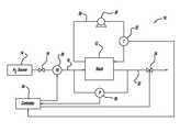
- FIG. 1is a schematic block diagram of a fuel cell system
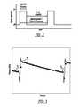
- FIG. 2is a graph with time on the horizontal axis and injector operation on the vertical axis showing an injector cycle for an injector in the system of FIG. 1 ;
- FIG. 3is a graph with time on the horizontal axis and pressure on the vertical axis showing the pressure in the anode sub-system in response to injector pulses;
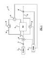
- FIG. 4is a flow block diagram showing a proposed algorithm for using anode sub-system pressures to determine anode flow and leak detection
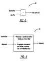
- FIG. 5is a flow block diagram showing an algorithm that sets the injector duty cycle
- FIG. 6is a flow block diagram showing an algorithm for reducing injector frequency for leak diagnostics.
- FIG. 1is a schematic block diagram of a fuel cell system 10 including a fuel cell stack 12 .
- Hydrogen gas from a high pressure hydrogen gas source 14such as a tank, is provided to the anode side of the fuel cell stack 12 on anode input line 16 .
- the hydrogen gas from the source 14is regulated by a pressure regulator 18 and injected into the stack 12 by an injector 20 .
- the injector 20is intended to represent a single injector or a bank of injectors suitable for the purposes described herein.
- Anode exhaust gas from the fuel cell stack 12is output on anode exhaust line 22 .
- a bleed valve 24is provided in the anode exhaust gas line 22 , and is periodically opened to bleed nitrogen from the anode side of the fuel cell stack 12 in a manner that is well understood to those skilled in the art. In this design, the bleed valve 24 will generally be closed where the stack 12 operates dead-ended. In alternate designs consistent with the discussion herein, the anode exhaust gas may be recirculated back to the anode input line 16 using an anode recirculation loop.
- the location of the pressure sensor 26is intended to represent any suitable location for measuring the pressure at the anode inlet, the anode outlet or a recycle line between the anode inlet and outlet.
- the system 10also includes a high temperature pump 28 that pumps a cooling fluid through a coolant loop 30 external to the stack 12 and through cooling fluid flow channels in the stack 12 in a manner that is well understood by those skilled in the art.
- a temperature sensor 32measures the temperature of the cooling fluid flowing through the coolant loop 30 , and can be provided at any suitable location in the coolant loop 30 , such as at an inlet to the stack 12 where the cooling fluid is typically the coolest or at an outlet of the fuel cell stack 12 where the cooling fluid is typically the hottest.
- a controller 34receives a pressure signal from the pressure sensor 26 and a temperature signal from the temperature sensor 32 , and controls the duty cycle of the injector 20 and the position of the bleed valve 24 .
- FIG. 2is a graph with time on the horizontal axis and injector operation between an off-state and an on-state on the vertical axis showing the cycle of the injector 20 .
- Two injector pulsesare shown having an injection duration for when the injector 20 is open.
- the time from when the injector 20 is turned on at one time to when the injector 20 is turned on at a next timeis the injector period and equals 1 divided by the injector frequency.
- the injector duty cycleis the injector duration divided by the injector period.
- a time from when the injector 20 is shut off to the next time when it is turned on itis known as the injector decay duration.
- the anode sub-system pressuremeasured by the pressure sensor 26 , is seen to rise as the instantaneous injection rate exceeds the fuel consumption rate by the stack 12 .
- This pressure risecan be used to measure the amount of hydrogen gas injected into the stack 12 for each injection event to determine the fuel flow to the stack 12 .
- N inj( P 2 ⁇ P 1 ) V/RT+N ii +N xoi (1)
- N injis the amount of fuel injected (moles)
- P 2is the anode sub-system pressure after the injection event (kPa)
- P 1is the anode sub-system pressure before the injection event (kPa)
- Vis the anode sub-system volume (L)
- Ris the ideal gas constant (8.315 kPa-L/mol-K)
- Tis the anode sub-system temperature (K)
- N iiis the fuel consumed due to reaction in the stack during the injection event (moles)
- N xoiis the gas or fuel cross-over during the injection event (moles).
- the amount of fuel injected N injis the amount of fuel injected during the injection event in moles.
- the fuel consumed N ii due to the reaction in the fuel cell stack 12 during the injection eventis the amount of fuel used by the stack 12 and could be determined by a measured current density of the stack 12 .
- the fuel cross-over N xoi during the injection eventis the amount of hydrogen gas that permeates through the membrane in the fuel cells during the injection event and is based on membrane permeability and is a function of many parameters, such as membrane material, anode pressure, cathode pressure, temperature, etc.
- the volume V of the anode sub-systemis known from the stack design.
- the anode sub-system temperature Tcan be provided by the stack coolant temperature using the sensor 32 .
- the fuel injection estimated by this methodwill have improved accuracy as the consumed and cross-over fuel are relatively small during the short injection period. The accuracy in the measurement is further improved by operating at a lower injector frequency as the pressure rise for an injection event is increased.
- FIG. 3is a graph with time on the horizontal axis and pressure on the vertical axis showing the anode sub-system pressure P during and between injection events.
- An injection eventis identified by a sharp drop in the anode sub-system pressure when the injector 20 is open and then a sharp rise in the anode sub-system pressure when the injector 20 is closed.
- the pressure P 1is provided just before the injector 20 is opened and the pressure P 2 is provided just after the injector 20 is closed.
- the pressure rise for each pulseis used to estimate the injected fuel.
- the pressure P 3is typically the same as the pressure P 1 and is the anode sub-system pressure at the next injection event.
- the pressure characteristics being discussed hereinare specific to a system with a jet pump driven recycle with a pressure transducer and the recycle loop.
- the initial pressure dropis due to the suction of the jet pump and the final rise due to the stopping of suction from the jet pump.
- the present inventionalso includes a pressure change over the entire injection/jet pump driven recycle of that.
- the injection event timingwill be known as the controller drives the injection operation.
- N leak( P 2 ⁇ P 3 ) V/RT ⁇ N io ⁇ N xoo (2)
- N leakis the amount of hydrogen gas leaking between injection events (moles)
- P 3is the anode sub-system pressure after the decay duration (kPa)
- N iois the fuel consumed due to reaction in the stack during the decay duration (moles)
- N xoois the fuel cross-over during the decay duration (moles).
- the leak estimatewill have improved accuracy as the fuel consumption rate is gradually reduced, typically 20-100 times lower than full power, while the leak rate is only slightly reduced, typically 4-8 times lower because the differential pressures that drive leaks are typically reduced at low pressure.
- the accuracy in this measurementis further improved with longer decay durations as the pressure change is increased.
- This type of extended decay durationcan be done on a very limited basis, such as once per drive cycle, to limit potential durability impact due to anode starvation.
- the leaked amountcan be normalized by the decay duration to obtain an average leak rate.
- the decay durationcan be used for normalization as the leak will assumed to be occurring at the same rate during the injection duration.
- the anodeis normally pressure controlled rather than flow controlled so that removal of the supply line pressure and temperature would not affect normal control.
- the startup pressurization and header purgeare done under flow control mode.
- the pressure response of the pressurization stepcan be used to estimate the average injector flow rate, and this injector operation can be continued for the header purge.
- Not all systemsuse a pressurization step and have a purge, but the pressure response at start up or any point in the operation of the system can be used to estimate the average injector flow rate to allow feed-forward control of the injector 20 .
- Supply line pressurehas also been used to verify tank valve closure, but the pressure in a gas handling unit can also be used.
- the supply line pressurecould be used to verify hydrogen availability. Without this pressure, the hydrogen availability could be determined after an anode fill attempt, if the anode fill increases pressure, then the supply line had pressure before the fill event. If the fill event is not accomplished, then the hydrogen supply valve would need to be opened to provide for an anode fill.
- the processcould rely on a gas handling unit pressure instead of the supply line pressure to determine whether the tank valve needs to be opened to support an off-time hydrogen addition.
- the injector flowis controlled by the injector duty cycle and the injector frequency. Injector flow is primarily controlled by the duty cycle, but at very low duty cycles, the injection duration would be too short for repeatable injector opening at higher injector frequencies. Thus, the injector frequency is decreased at low power (low duty cycle) so that each injection event can be of reasonable duration. For an injector/ejector driven recycle system, a minimum injection duration is also desired so that the full differential pressure can be developed to facilitate water movement within and from the anode flow channels of the stack 12 .
- FIG. 4is a flow block diagram for a system 40 that shows a method to estimate the maximum injector flow, as discussed above.
- the maximum injector flowis determined from the anode sub-system pressure response of previous injection events. Due to the pulsed nature of the flow, the anode sub-system pressure signal must be filtered to extract the pressure at the desired time in the injection cycle. Ideally, a signal of the injector opening can be used as the logic filter for the pressure signal. Preferably, the injector open signal is available as this can be used to determine the time within the injection cycle. Otherwise, the pressure trace can be used to infer when injection events occurred.
- Box 42receives the pressure signal from the pressure sensor 26 and a signal indicating that the injector 20 is open, and outputs the pressures P 1 , P 2 and P 3 .
- An injection estimate processor box 44receives the pressures P 1 and P 2 from the box 42 and the fuel consumed due to reaction during the injection event N ii , the fuel cross-over during the injection event N xoi and the temperature signal from the temperature sensor 32 .
- the processor box 44uses equation (1) to calculate the amount of fuel injected N inj .
- the injection estimate N injis used to determine the amount of hydrogen injected during an injection event.
- the injection estimation N injis then scaled to 100% DC at box 46 , which receives the injector duty cycle and frequency, to the maximum flow based on the duty cycle of the injector 20 .
- a correctioncan be used based on injection duration, which is determined from injector frequency and duty cycle, to account for injector opening and closing times. It is understood that the injector estimate should only be done when the anode bleed valve 24 is closed. However, in alternate embodiments, it may be possible to estimate the bleed flow and correct the anode flow based on the estimates.
- the value obtained from the maximum injector flowincludes the effects from fuel supply pressure and temperature, as well as the injector flow coefficient, and can be used for several injection cycles as the supply conditions will not change very rapidly as the upstream volume is relatively large compared to the injection volume.
- the maximum injector flowcan be averaged and/or filtered to obtain a more smoothed control response.
- FIG. 5is a block diagram of a system 52 showing one process for determining the injector duty cycle that includes dividing the desired flow through the injector 20 by the maximum flow.
- a leak estimator processor box 48receives the pressures P 2 and P 3 , the fuel consumed due to the reaction during the decay duration N io and the fuel cross-over during the decay duration N xoo , and calculates a leak estimate N leak using equation (2).
- the value N leakis then scaled to full time at box 50 , which also receives the injector duty cycle and frequency to determine leak rate.
- the leak estimate from equation (2)uses the pressure decay between the pressures P 2 and P 3 between injection events to determine the hydrogen loss in the anode sub-system. A portion of this hydrogen gas is consumed as determined by the measured current density and some is expected to cross-over the membrane.
- the differenceis considered to be a leak during the time of the pressure decay.
- the leak signalcan be scaled to a leak rate by this time period, i.e., the time between the pressure decay pressure measurements P 2 and P 3 , which can be approximated as the decay duration based on injector frequency and duty cycle.
- an estimate of the leakagetakes the difference between the metered input and consumed hydrogen gas as determined by the measured current density and the expected cross-over.
- This leak detection methodcan also be used with the proposed method of fuel metering without the fuel supply pressure and temperature.
- the leak estimatecan be integrated over several injection cycles to improve the accuracy.
- leak estimatesshould only be performed when the anode bleed valve 24 is closed. If the leak rate exceeds a threshold value, the system could set a diagnostic to request service. A likely source of an excess leak is a stuck open bleed valve, so corrective action may also include increased exhaust dilution.
- the decay durationcan be increased by using a lower injection frequency and the decay duration is also longer at lower duty cycles. Longer decay durations can be used periodically to provide a more accurate leak estimate when requested for diagnostic purposes.
- FIG. 6is a block diagram of a system 54 to illustrate this. A very long decay is not routinely desired due to the higher pressure cycling and potential for anode starvation with longer times between injection events, which could impact membrane durability. For this reason, the longer decay durations would preferably be infrequently used only as needed for leakage diagnostics.
- Corrections for nitrogen cross-overcan be used in the injector and leak estimates.
- a correction for leakagecan be used in the injector estimate. This leakage estimate could also be used to increase the desired flow request to compensate for the leakage.
Landscapes
- Physics & Mathematics (AREA)
- General Physics & Mathematics (AREA)
- Fluid Mechanics (AREA)
- Sustainable Development (AREA)
- Engineering & Computer Science (AREA)
- Manufacturing & Machinery (AREA)
- Life Sciences & Earth Sciences (AREA)
- Sustainable Energy (AREA)
- Chemical & Material Sciences (AREA)
- Chemical Kinetics & Catalysis (AREA)
- Electrochemistry (AREA)
- General Chemical & Material Sciences (AREA)
- Fuel Cell (AREA)
Abstract
Description
Ninj=(P2−P1)V/RT+Nii+Nxoi (1)
Where Ninjis the amount of fuel injected (moles), P2is the anode sub-system pressure after the injection event (kPa), P1is the anode sub-system pressure before the injection event (kPa), V is the anode sub-system volume (L), R is the ideal gas constant (8.315 kPa-L/mol-K), T is the anode sub-system temperature (K), Niiis the fuel consumed due to reaction in the stack during the injection event (moles), and Nxoiis the gas or fuel cross-over during the injection event (moles).
Nleak=(P2−P3)V/RT−Nio−Nxoo (2)
Where Nleakis the amount of hydrogen gas leaking between injection events (moles), P3is the anode sub-system pressure after the decay duration (kPa), Niois the fuel consumed due to reaction in the stack during the decay duration (moles) and Nxoois the fuel cross-over during the decay duration (moles).
Claims (22)
Nleak=(P2−P3)V/RT−Nio−Nxoo
Ninj=(P2−P1)V/RT+Nii+Nxoi
Ninj=(P2−P1)V/RT+Nii+Nxoi
Nleak=(P2−P3)V/RT−Nio−Nxoo
Ninj=(P2−P1)V/RT+Nii+Nxoi
Nleak=(P2−P3)V/RT−Nio−Nxoo
Priority Applications (3)
| Application Number | Priority Date | Filing Date | Title |
|---|---|---|---|
| US12/636,276US8387441B2 (en) | 2009-12-11 | 2009-12-11 | Injector flow measurement for fuel cell applications |
| DE102010053626.1ADE102010053626B4 (en) | 2009-12-11 | 2010-12-07 | A method of determining a fuel flow through a pulsed injector |
| CN2010105884778ACN102128651B (en) | 2009-12-11 | 2010-12-10 | Injector flow measurement for fuel cell applications |
Applications Claiming Priority (1)
| Application Number | Priority Date | Filing Date | Title |
|---|---|---|---|
| US12/636,276US8387441B2 (en) | 2009-12-11 | 2009-12-11 | Injector flow measurement for fuel cell applications |
Publications (2)
| Publication Number | Publication Date |
|---|---|
| US20110138883A1 US20110138883A1 (en) | 2011-06-16 |
| US8387441B2true US8387441B2 (en) | 2013-03-05 |
Family
ID=44141406
Family Applications (1)
| Application Number | Title | Priority Date | Filing Date |
|---|---|---|---|
| US12/636,276Active2031-01-23US8387441B2 (en) | 2009-12-11 | 2009-12-11 | Injector flow measurement for fuel cell applications |
Country Status (3)
| Country | Link |
|---|---|
| US (1) | US8387441B2 (en) |
| CN (1) | CN102128651B (en) |
| DE (1) | DE102010053626B4 (en) |
Cited By (24)
| Publication number | Priority date | Publication date | Assignee | Title |
|---|---|---|---|---|
| US20140130777A1 (en)* | 2011-07-11 | 2014-05-15 | Toyota Jidosha Kabushiki Kaisha | Detection method of airtight failure in working-gas circulating type gas engine, and working-gas circulating type gas engine using the method |
| US8839815B2 (en) | 2011-12-15 | 2014-09-23 | Honeywell International Inc. | Gas valve with electronic cycle counter |
| US8899264B2 (en) | 2011-12-15 | 2014-12-02 | Honeywell International Inc. | Gas valve with electronic proof of closure system |
| US8905063B2 (en) | 2011-12-15 | 2014-12-09 | Honeywell International Inc. | Gas valve with fuel rate monitor |
| US8947242B2 (en) | 2011-12-15 | 2015-02-03 | Honeywell International Inc. | Gas valve with valve leakage test |
| US9234661B2 (en) | 2012-09-15 | 2016-01-12 | Honeywell International Inc. | Burner control system |
| US9557059B2 (en) | 2011-12-15 | 2017-01-31 | Honeywell International Inc | Gas valve with communication link |
| US9645584B2 (en) | 2014-09-17 | 2017-05-09 | Honeywell International Inc. | Gas valve with electronic health monitoring |
| US9683674B2 (en) | 2013-10-29 | 2017-06-20 | Honeywell Technologies Sarl | Regulating device |
| US9685667B2 (en) | 2014-08-06 | 2017-06-20 | Ford Global Technologies, Llc | Methods for testing anode integrity during fuel cell vehicle operation |
| US9835265B2 (en) | 2011-12-15 | 2017-12-05 | Honeywell International Inc. | Valve with actuator diagnostics |
| US9846440B2 (en) | 2011-12-15 | 2017-12-19 | Honeywell International Inc. | Valve controller configured to estimate fuel comsumption |
| US9851103B2 (en) | 2011-12-15 | 2017-12-26 | Honeywell International Inc. | Gas valve with overpressure diagnostics |
| US9995486B2 (en) | 2011-12-15 | 2018-06-12 | Honeywell International Inc. | Gas valve with high/low gas pressure detection |
| US10024439B2 (en) | 2013-12-16 | 2018-07-17 | Honeywell International Inc. | Valve over-travel mechanism |
| US10199670B2 (en) | 2016-04-08 | 2019-02-05 | Intelligent Energy Limited | Power generator having reference pressure chamber |
| US10422531B2 (en) | 2012-09-15 | 2019-09-24 | Honeywell International Inc. | System and approach for controlling a combustion chamber |
| US10503181B2 (en) | 2016-01-13 | 2019-12-10 | Honeywell International Inc. | Pressure regulator |
| US10564062B2 (en) | 2016-10-19 | 2020-02-18 | Honeywell International Inc. | Human-machine interface for gas valve |
| US10697815B2 (en) | 2018-06-09 | 2020-06-30 | Honeywell International Inc. | System and methods for mitigating condensation in a sensor module |
| US11073281B2 (en) | 2017-12-29 | 2021-07-27 | Honeywell International Inc. | Closed-loop programming and control of a combustion appliance |
| US11251447B2 (en)* | 2020-02-12 | 2022-02-15 | GM Global Technology Operations LLC | Process and system for detecting low-level fuel injector leakage in a fuel cell system |
| US11735751B1 (en) | 2022-03-21 | 2023-08-22 | GM Global Technology Operations LLC | Intelligent fuel cell systems and control logic for smart use of anode header drain valves for FCS bleed and drainage |
| US11894588B2 (en) | 2021-09-14 | 2024-02-06 | GM Global Technology Operations LLC | Fuel cell propulsion system with a fuel cell stack for a motor vehicle and process for controlling a temperature of the fuel cell stack |
Families Citing this family (18)
| Publication number | Priority date | Publication date | Assignee | Title |
|---|---|---|---|---|
| US20110200900A1 (en)* | 2010-02-17 | 2011-08-18 | Gm Global Technology Operations, Inc. | Feed forward fuel control algorithm to decrease fuel cell vehicle start up time |
| DE102011105054A1 (en)* | 2011-06-21 | 2012-12-27 | Volkswagen Aktiengesellschaft | Fuel cell operating method for driving motor car, involves carrying out measure for amplification of convection and/or of turbulence within anode portion during starting procedure of fuel cell |
| US8852824B2 (en)* | 2011-11-14 | 2014-10-07 | GM Global Technology Operations LLC | Method to generate H2-exhaust sensor test pulse using electrically controlled pressure regulator |
| US9105887B2 (en) | 2011-12-08 | 2015-08-11 | GM Global Technology Operations LLC | Anode injector control algorithm for a low frequency discrete output |
| US9074770B2 (en)* | 2011-12-15 | 2015-07-07 | Honeywell International Inc. | Gas valve with electronic valve proving system |
| DE102012005690B4 (en)* | 2012-03-21 | 2015-03-05 | Audi Ag | Method and arrangement for operating a fuel cell system |
| US9564648B2 (en) | 2012-12-06 | 2017-02-07 | GM Global Technology Operations LLC | Anode leak location detection |
| US9841122B2 (en) | 2014-09-09 | 2017-12-12 | Honeywell International Inc. | Gas valve with electronic valve proving system |
| JP6299683B2 (en) | 2015-06-25 | 2018-03-28 | トヨタ自動車株式会社 | Fuel cell system |
| EP3165748A1 (en)* | 2015-11-04 | 2017-05-10 | GE Jenbacher GmbH & Co. OG | Internal combustion engine with injection amount control |
| DE102016215027A1 (en)* | 2016-08-11 | 2018-02-15 | Robert Bosch Gmbh | fuel cell device |
| CN106353103B (en)* | 2016-10-12 | 2019-04-05 | 中国船舶重工集团公司第七一一研究所 | A kind of high-power gas injector test method |
| DE102017208604A1 (en)* | 2017-05-22 | 2018-11-22 | Robert Bosch Gmbh | Method for detecting a leak in a fuel cell system and fuel cell system |
| CN109751132B (en)* | 2017-11-07 | 2024-07-19 | 北京慨尔康科技发展有限公司 | A throttle valve body |
| CN109751422B (en)* | 2017-11-07 | 2024-02-20 | 北京慨尔康科技发展有限公司 | A control method for a power system |
| CN109751443A (en)* | 2017-11-07 | 2019-05-14 | 北京慨尔康科技发展有限公司 | A kind of throttler valve and its control method |
| AT522100B1 (en)* | 2019-02-08 | 2022-01-15 | Avl List Gmbh | Method for adjusting an injection strategy for an injector of a fuel cell system |
| CN112881024B (en)* | 2021-01-15 | 2023-03-31 | 中汽研汽车检验中心(天津)有限公司 | Hydrogen injector testing device and testing method for hydrogen fuel cell engine |
Citations (24)
| Publication number | Priority date | Publication date | Assignee | Title |
|---|---|---|---|---|
| US6156447A (en)* | 1996-11-28 | 2000-12-05 | Siemens Aktiengesellschaft | Method for identifying a gas leak, and fuel cell system |
| US20030022044A1 (en)* | 2001-07-26 | 2003-01-30 | Honda Giken Kogyo Kabushiki Kaisha | Gas leak detection method for fuel cell |
| US20040028964A1 (en)* | 2002-08-12 | 2004-02-12 | Smaling Rudolf M. | Apparatus and method for controlling the oxygen-to-carbon ratio of a fuel reformer |
| US6918382B2 (en)* | 2002-08-26 | 2005-07-19 | Energy Conversion Devices, Inc. | Hydrogen powered scooter |
| US20060174624A1 (en)* | 2003-01-04 | 2006-08-10 | Tony Grabowski | Hydrogen fuelled hybrid powertrain and vehicle |
| US20070180769A1 (en)* | 2006-02-08 | 2007-08-09 | Bonadies Joseph V | Fuel reformer having closed loop control of air/fuel ratio |
| US20070207355A1 (en)* | 2004-09-16 | 2007-09-06 | Toyota Jidosha Kabushiki Kaisha | Fuel Cell System and Gas Leak Determination Method for Fuel Cell System |
| US20070218330A1 (en)* | 2004-04-23 | 2007-09-20 | Toyota Jidosha Kabushiki Kaisha | Fuel Cell System |
| US7320840B2 (en) | 2003-07-17 | 2008-01-22 | General Motors Corporation | Combination of injector-ejector for fuel cell systems |
| US20080118793A1 (en)* | 2004-05-21 | 2008-05-22 | Chapman Ivan D | Fluid flow pulsing for increased stability in pem fuel cell |
| US20080141760A1 (en)* | 2006-12-19 | 2008-06-19 | Gm Global Technology Operations, Inc. | Leak detection in a fuel cell system |
| DE102006059030A1 (en)* | 2006-12-14 | 2008-06-19 | Daimler Ag | Leakage test in a fuel cell system |
| US7393602B2 (en)* | 2005-04-14 | 2008-07-01 | Gm Global Technology Operations, Inc. | Method to begin coolant circulation to prevent MEA overheating during cold start |
| US20090035614A1 (en)* | 2007-08-03 | 2009-02-05 | Honda Motor Co., Ltd. | Fuel cell system and method for operating the same |
| JP2009059570A (en)* | 2007-08-31 | 2009-03-19 | Honda Motor Co Ltd | Fuel cell system |
| EP2207232A1 (en)* | 2007-11-08 | 2010-07-14 | Toyota Jidosha Kabushiki Kaisha | Fuel cell system and hydrogen leak judgment method in the system |
| US7771854B2 (en)* | 2004-11-30 | 2010-08-10 | Honda Motor Co., Ltd. | Fuel cell system and method of detecting failure in a fuel gas channel of fuel cell system |
| US7797090B2 (en)* | 2004-12-02 | 2010-09-14 | Ford Motor Company | Method for monitoring hydrogen vehicles |
| US7829233B2 (en)* | 2005-08-09 | 2010-11-09 | Toyota Jidosha Kabushiki Kaisha | Fuel cell system and method for judging fuel gas leak in a fuel cell system |
| US20110008699A1 (en)* | 2007-07-04 | 2011-01-13 | Toyota Jidosha Kabushiki Kaisha | Fuel cell system and control unit for fuel cell system |
| US20110087441A1 (en)* | 2009-10-09 | 2011-04-14 | Gm Global Technology Operations, Inc. | Online method to estimate hydrogen concentration estimation in fuel cell systems at shutdown and startup |
| US7942035B2 (en)* | 2008-04-09 | 2011-05-17 | Ford Motor Company | Anode leak test implementation |
| US8067127B2 (en)* | 2003-12-25 | 2011-11-29 | Toyota Jidosha Kabushiki Kaisha | Fuel cell system and control method thereof for detecting a chemical short |
| US8071243B2 (en)* | 2005-12-02 | 2011-12-06 | Panasonic Corporation | Fuel cell system |
Family Cites Families (1)
| Publication number | Priority date | Publication date | Assignee | Title |
|---|---|---|---|---|
| JP4756476B2 (en)* | 2006-12-07 | 2011-08-24 | トヨタ自動車株式会社 | Fuel cell system and fuel cell vehicle |
- 2009
- 2009-12-11USUS12/636,276patent/US8387441B2/enactiveActive
- 2010
- 2010-12-07DEDE102010053626.1Apatent/DE102010053626B4/enactiveActive
- 2010-12-10CNCN2010105884778Apatent/CN102128651B/enactiveActive
Patent Citations (24)
| Publication number | Priority date | Publication date | Assignee | Title |
|---|---|---|---|---|
| US6156447A (en)* | 1996-11-28 | 2000-12-05 | Siemens Aktiengesellschaft | Method for identifying a gas leak, and fuel cell system |
| US20030022044A1 (en)* | 2001-07-26 | 2003-01-30 | Honda Giken Kogyo Kabushiki Kaisha | Gas leak detection method for fuel cell |
| US20040028964A1 (en)* | 2002-08-12 | 2004-02-12 | Smaling Rudolf M. | Apparatus and method for controlling the oxygen-to-carbon ratio of a fuel reformer |
| US6918382B2 (en)* | 2002-08-26 | 2005-07-19 | Energy Conversion Devices, Inc. | Hydrogen powered scooter |
| US20060174624A1 (en)* | 2003-01-04 | 2006-08-10 | Tony Grabowski | Hydrogen fuelled hybrid powertrain and vehicle |
| US7320840B2 (en) | 2003-07-17 | 2008-01-22 | General Motors Corporation | Combination of injector-ejector for fuel cell systems |
| US8067127B2 (en)* | 2003-12-25 | 2011-11-29 | Toyota Jidosha Kabushiki Kaisha | Fuel cell system and control method thereof for detecting a chemical short |
| US20070218330A1 (en)* | 2004-04-23 | 2007-09-20 | Toyota Jidosha Kabushiki Kaisha | Fuel Cell System |
| US20080118793A1 (en)* | 2004-05-21 | 2008-05-22 | Chapman Ivan D | Fluid flow pulsing for increased stability in pem fuel cell |
| US20070207355A1 (en)* | 2004-09-16 | 2007-09-06 | Toyota Jidosha Kabushiki Kaisha | Fuel Cell System and Gas Leak Determination Method for Fuel Cell System |
| US7771854B2 (en)* | 2004-11-30 | 2010-08-10 | Honda Motor Co., Ltd. | Fuel cell system and method of detecting failure in a fuel gas channel of fuel cell system |
| US7797090B2 (en)* | 2004-12-02 | 2010-09-14 | Ford Motor Company | Method for monitoring hydrogen vehicles |
| US7393602B2 (en)* | 2005-04-14 | 2008-07-01 | Gm Global Technology Operations, Inc. | Method to begin coolant circulation to prevent MEA overheating during cold start |
| US7829233B2 (en)* | 2005-08-09 | 2010-11-09 | Toyota Jidosha Kabushiki Kaisha | Fuel cell system and method for judging fuel gas leak in a fuel cell system |
| US8071243B2 (en)* | 2005-12-02 | 2011-12-06 | Panasonic Corporation | Fuel cell system |
| US20070180769A1 (en)* | 2006-02-08 | 2007-08-09 | Bonadies Joseph V | Fuel reformer having closed loop control of air/fuel ratio |
| DE102006059030A1 (en)* | 2006-12-14 | 2008-06-19 | Daimler Ag | Leakage test in a fuel cell system |
| US20080141760A1 (en)* | 2006-12-19 | 2008-06-19 | Gm Global Technology Operations, Inc. | Leak detection in a fuel cell system |
| US20110008699A1 (en)* | 2007-07-04 | 2011-01-13 | Toyota Jidosha Kabushiki Kaisha | Fuel cell system and control unit for fuel cell system |
| US20090035614A1 (en)* | 2007-08-03 | 2009-02-05 | Honda Motor Co., Ltd. | Fuel cell system and method for operating the same |
| JP2009059570A (en)* | 2007-08-31 | 2009-03-19 | Honda Motor Co Ltd | Fuel cell system |
| EP2207232A1 (en)* | 2007-11-08 | 2010-07-14 | Toyota Jidosha Kabushiki Kaisha | Fuel cell system and hydrogen leak judgment method in the system |
| US7942035B2 (en)* | 2008-04-09 | 2011-05-17 | Ford Motor Company | Anode leak test implementation |
| US20110087441A1 (en)* | 2009-10-09 | 2011-04-14 | Gm Global Technology Operations, Inc. | Online method to estimate hydrogen concentration estimation in fuel cell systems at shutdown and startup |
Cited By (31)
| Publication number | Priority date | Publication date | Assignee | Title |
|---|---|---|---|---|
| US9447752B2 (en)* | 2011-07-11 | 2016-09-20 | Toyota Jidosha Kabushiki Kaisha | Detection method of airtight failure in working-gas circulating type gas engine, and working-gas circulating type gas engine using the method |
| US20140130777A1 (en)* | 2011-07-11 | 2014-05-15 | Toyota Jidosha Kabushiki Kaisha | Detection method of airtight failure in working-gas circulating type gas engine, and working-gas circulating type gas engine using the method |
| US9851103B2 (en) | 2011-12-15 | 2017-12-26 | Honeywell International Inc. | Gas valve with overpressure diagnostics |
| US9835265B2 (en) | 2011-12-15 | 2017-12-05 | Honeywell International Inc. | Valve with actuator diagnostics |
| US8947242B2 (en) | 2011-12-15 | 2015-02-03 | Honeywell International Inc. | Gas valve with valve leakage test |
| US8905063B2 (en) | 2011-12-15 | 2014-12-09 | Honeywell International Inc. | Gas valve with fuel rate monitor |
| US8899264B2 (en) | 2011-12-15 | 2014-12-02 | Honeywell International Inc. | Gas valve with electronic proof of closure system |
| US9557059B2 (en) | 2011-12-15 | 2017-01-31 | Honeywell International Inc | Gas valve with communication link |
| US9995486B2 (en) | 2011-12-15 | 2018-06-12 | Honeywell International Inc. | Gas valve with high/low gas pressure detection |
| US8839815B2 (en) | 2011-12-15 | 2014-09-23 | Honeywell International Inc. | Gas valve with electronic cycle counter |
| US10851993B2 (en) | 2011-12-15 | 2020-12-01 | Honeywell International Inc. | Gas valve with overpressure diagnostics |
| US10697632B2 (en) | 2011-12-15 | 2020-06-30 | Honeywell International Inc. | Gas valve with communication link |
| US9846440B2 (en) | 2011-12-15 | 2017-12-19 | Honeywell International Inc. | Valve controller configured to estimate fuel comsumption |
| US10422531B2 (en) | 2012-09-15 | 2019-09-24 | Honeywell International Inc. | System and approach for controlling a combustion chamber |
| US9657946B2 (en) | 2012-09-15 | 2017-05-23 | Honeywell International Inc. | Burner control system |
| US11421875B2 (en) | 2012-09-15 | 2022-08-23 | Honeywell International Inc. | Burner control system |
| US9234661B2 (en) | 2012-09-15 | 2016-01-12 | Honeywell International Inc. | Burner control system |
| US9683674B2 (en) | 2013-10-29 | 2017-06-20 | Honeywell Technologies Sarl | Regulating device |
| US10215291B2 (en) | 2013-10-29 | 2019-02-26 | Honeywell International Inc. | Regulating device |
| US10024439B2 (en) | 2013-12-16 | 2018-07-17 | Honeywell International Inc. | Valve over-travel mechanism |
| US9685667B2 (en) | 2014-08-06 | 2017-06-20 | Ford Global Technologies, Llc | Methods for testing anode integrity during fuel cell vehicle operation |
| US9645584B2 (en) | 2014-09-17 | 2017-05-09 | Honeywell International Inc. | Gas valve with electronic health monitoring |
| US10203049B2 (en) | 2014-09-17 | 2019-02-12 | Honeywell International Inc. | Gas valve with electronic health monitoring |
| US10503181B2 (en) | 2016-01-13 | 2019-12-10 | Honeywell International Inc. | Pressure regulator |
| US10199670B2 (en) | 2016-04-08 | 2019-02-05 | Intelligent Energy Limited | Power generator having reference pressure chamber |
| US10564062B2 (en) | 2016-10-19 | 2020-02-18 | Honeywell International Inc. | Human-machine interface for gas valve |
| US11073281B2 (en) | 2017-12-29 | 2021-07-27 | Honeywell International Inc. | Closed-loop programming and control of a combustion appliance |
| US10697815B2 (en) | 2018-06-09 | 2020-06-30 | Honeywell International Inc. | System and methods for mitigating condensation in a sensor module |
| US11251447B2 (en)* | 2020-02-12 | 2022-02-15 | GM Global Technology Operations LLC | Process and system for detecting low-level fuel injector leakage in a fuel cell system |
| US11894588B2 (en) | 2021-09-14 | 2024-02-06 | GM Global Technology Operations LLC | Fuel cell propulsion system with a fuel cell stack for a motor vehicle and process for controlling a temperature of the fuel cell stack |
| US11735751B1 (en) | 2022-03-21 | 2023-08-22 | GM Global Technology Operations LLC | Intelligent fuel cell systems and control logic for smart use of anode header drain valves for FCS bleed and drainage |
Also Published As
| Publication number | Publication date |
|---|---|
| DE102010053626A1 (en) | 2011-06-30 |
| CN102128651A (en) | 2011-07-20 |
| CN102128651B (en) | 2013-05-29 |
| DE102010053626B4 (en) | 2014-02-13 |
| US20110138883A1 (en) | 2011-06-16 |
Similar Documents
| Publication | Publication Date | Title |
|---|---|---|
| US8387441B2 (en) | Injector flow measurement for fuel cell applications | |
| US8524405B2 (en) | Detection of small anode leaks in fuel cell systems | |
| CN100563053C (en) | Fuel cell system | |
| US20110143243A1 (en) | Fuel cell operational methods for hydrogen addition after shutdown | |
| US9660278B2 (en) | Method for detecting orifice flow phase transition in a pressure-controlled anode | |
| CN111224132B (en) | Shutdown purging method and system for fuel cell | |
| US20130164644A1 (en) | System and method for controlling pressure oscillation in anode of fuel cell stack | |
| US20090081492A1 (en) | Fuel Cell System, Moving Object Equipped With Fuel Cell System, and Abnormality Judgement Method For Fuel Cell System | |
| US8679691B2 (en) | Injector opening delay diagnostic strategy | |
| CN102538880B (en) | Flow estimation based on anode pressure response in fuel cell system | |
| US11171347B2 (en) | Fuel cell system to control output of a fuel cell stack | |
| JP2017069193A (en) | Validation and correction of gen 2 anode h2 concentration estimation | |
| US8623567B2 (en) | Method to detect gross loss in coolant based on current feedback from the high temperature pump | |
| US20140080018A1 (en) | Fuel cell system and method of controlling the fuel cell system | |
| US8409762B2 (en) | Adaptive method to control fuel delivery injector with modeling uncertainties in a fuel cell system | |
| US9080938B2 (en) | Extremum seeking algorithm in a variable time interval to detect anode pressure sensor stuck failure in a fuel cell system | |
| CN103094589B (en) | Fuel cell operation with a failed open injector | |
| US9018961B2 (en) | Diagnosing injector failure via stack voltage response analysis | |
| US20110200900A1 (en) | Feed forward fuel control algorithm to decrease fuel cell vehicle start up time | |
| US8642223B2 (en) | Control strategy to prevent unexpected hydrogen flow to the cathode due to a failed pressure sensor while catalytic heating | |
| CN102881928B (en) | Leakage diagnostic for a fuel cell system in idle-stop mode | |
| US20140349208A1 (en) | Fuel cell system | |
| JP2010272505A (en) | Fuel cell system | |
| KR20250088066A (en) | Fuel cell system and fuel cell system control method | |
| CN117334968A (en) | Fuel cell engine with stop valve fault recognition and processing functions |
Legal Events
| Date | Code | Title | Description |
|---|---|---|---|
| AS | Assignment | Owner name:GM GLOBAL TECHNOLOGY OPERATIONS, INC., MICHIGAN Free format text:ASSIGNMENT OF ASSIGNORS INTEREST;ASSIGNORS:FALTA, STEVEN R.;GOEBEL, STEVEN G.;DI FIORE, DANIEL C.;AND OTHERS;SIGNING DATES FROM 20091007 TO 20091008;REEL/FRAME:023651/0028 | |
| AS | Assignment | Owner name:UNITED STATES DEPARTMENT OF THE TREASURY, DISTRICT Free format text:SECURITY AGREEMENT;ASSIGNOR:GM GLOBAL TECHNOLOGY OPERATIONS, INC.;REEL/FRAME:023989/0155 Effective date:20090710 Owner name:UAW RETIREE MEDICAL BENEFITS TRUST, MICHIGAN Free format text:SECURITY AGREEMENT;ASSIGNOR:GM GLOBAL TECHNOLOGY OPERATIONS, INC.;REEL/FRAME:023990/0001 Effective date:20090710 | |
| AS | Assignment | Owner name:GM GLOBAL TECHNOLOGY OPERATIONS, INC., MICHIGAN Free format text:RELEASE BY SECURED PARTY;ASSIGNOR:UNITED STATES DEPARTMENT OF THE TREASURY;REEL/FRAME:025246/0234 Effective date:20100420 | |
| AS | Assignment | Owner name:GM GLOBAL TECHNOLOGY OPERATIONS, INC., MICHIGAN Free format text:RELEASE BY SECURED PARTY;ASSIGNOR:UAW RETIREE MEDICAL BENEFITS TRUST;REEL/FRAME:025315/0136 Effective date:20101026 | |
| AS | Assignment | Owner name:WILMINGTON TRUST COMPANY, DELAWARE Free format text:SECURITY AGREEMENT;ASSIGNOR:GM GLOBAL TECHNOLOGY OPERATIONS, INC.;REEL/FRAME:025327/0156 Effective date:20101027 | |
| AS | Assignment | Owner name:GM GLOBAL TECHNOLOGY OPERATIONS LLC, MICHIGAN Free format text:CHANGE OF NAME;ASSIGNOR:GM GLOBAL TECHNOLOGY OPERATIONS, INC.;REEL/FRAME:025781/0299 Effective date:20101202 | |
| FEPP | Fee payment procedure | Free format text:PAYOR NUMBER ASSIGNED (ORIGINAL EVENT CODE: ASPN); ENTITY STATUS OF PATENT OWNER: LARGE ENTITY | |
| STCF | Information on status: patent grant | Free format text:PATENTED CASE | |
| AS | Assignment | Owner name:GM GLOBAL TECHNOLOGY OPERATIONS LLC, MICHIGAN Free format text:RELEASE BY SECURED PARTY;ASSIGNOR:WILMINGTON TRUST COMPANY;REEL/FRAME:034287/0001 Effective date:20141017 | |
| FPAY | Fee payment | Year of fee payment:4 | |
| MAFP | Maintenance fee payment | Free format text:PAYMENT OF MAINTENANCE FEE, 8TH YEAR, LARGE ENTITY (ORIGINAL EVENT CODE: M1552); ENTITY STATUS OF PATENT OWNER: LARGE ENTITY Year of fee payment:8 | |
| MAFP | Maintenance fee payment | Free format text:PAYMENT OF MAINTENANCE FEE, 12TH YEAR, LARGE ENTITY (ORIGINAL EVENT CODE: M1553); ENTITY STATUS OF PATENT OWNER: LARGE ENTITY Year of fee payment:12 |