US8386112B2 - Vessel hull robot navigation subsystem - Google Patents
Vessel hull robot navigation subsystemDownload PDFInfo
- Publication number
- US8386112B2 US8386112B2US12/800,486US80048610AUS8386112B2US 8386112 B2US8386112 B2US 8386112B2US 80048610 AUS80048610 AUS 80048610AUS 8386112 B2US8386112 B2US 8386112B2
- Authority
- US
- United States
- Prior art keywords
- robot
- hull
- vessel
- subsystem
- data
- Prior art date
- Legal status (The legal status is an assumption and is not a legal conclusion. Google has not performed a legal analysis and makes no representation as to the accuracy of the status listed.)
- Active, expires
Links
Images


Classifications
- B—PERFORMING OPERATIONS; TRANSPORTING
- B63—SHIPS OR OTHER WATERBORNE VESSELS; RELATED EQUIPMENT
- B63B—SHIPS OR OTHER WATERBORNE VESSELS; EQUIPMENT FOR SHIPPING
- B63B59/00—Hull protection specially adapted for vessels; Cleaning devices specially adapted for vessels
- B63B59/06—Cleaning devices for hulls
- B63B59/08—Cleaning devices for hulls of underwater surfaces while afloat
- G—PHYSICS
- G05—CONTROLLING; REGULATING
- G05D—SYSTEMS FOR CONTROLLING OR REGULATING NON-ELECTRIC VARIABLES
- G05D1/00—Control of position, course, altitude or attitude of land, water, air or space vehicles, e.g. using automatic pilots
- G05D1/02—Control of position or course in two dimensions
- G05D1/021—Control of position or course in two dimensions specially adapted to land vehicles
- G05D1/0276—Control of position or course in two dimensions specially adapted to land vehicles using signals provided by a source external to the vehicle
- B—PERFORMING OPERATIONS; TRANSPORTING
- B25—HAND TOOLS; PORTABLE POWER-DRIVEN TOOLS; MANIPULATORS
- B25J—MANIPULATORS; CHAMBERS PROVIDED WITH MANIPULATION DEVICES
- B25J5/00—Manipulators mounted on wheels or on carriages
- B—PERFORMING OPERATIONS; TRANSPORTING
- B63—SHIPS OR OTHER WATERBORNE VESSELS; RELATED EQUIPMENT
- B63B—SHIPS OR OTHER WATERBORNE VESSELS; EQUIPMENT FOR SHIPPING
- B63B59/00—Hull protection specially adapted for vessels; Cleaning devices specially adapted for vessels
- B63B59/06—Cleaning devices for hulls
- B63B59/10—Cleaning devices for hulls using trolleys or the like driven along the surface
- G—PHYSICS
- G01—MEASURING; TESTING
- G01C—MEASURING DISTANCES, LEVELS OR BEARINGS; SURVEYING; NAVIGATION; GYROSCOPIC INSTRUMENTS; PHOTOGRAMMETRY OR VIDEOGRAMMETRY
- G01C21/00—Navigation; Navigational instruments not provided for in groups G01C1/00 - G01C19/00
- G—PHYSICS
- G05—CONTROLLING; REGULATING
- G05D—SYSTEMS FOR CONTROLLING OR REGULATING NON-ELECTRIC VARIABLES
- G05D1/00—Control of position, course, altitude or attitude of land, water, air or space vehicles, e.g. using automatic pilots
- G05D1/02—Control of position or course in two dimensions
- G05D1/021—Control of position or course in two dimensions specially adapted to land vehicles
- G05D1/0268—Control of position or course in two dimensions specially adapted to land vehicles using internal positioning means
- G05D1/027—Control of position or course in two dimensions specially adapted to land vehicles using internal positioning means comprising intertial navigation means, e.g. azimuth detector
- G—PHYSICS
- G05—CONTROLLING; REGULATING
- G05D—SYSTEMS FOR CONTROLLING OR REGULATING NON-ELECTRIC VARIABLES
- G05D1/00—Control of position, course, altitude or attitude of land, water, air or space vehicles, e.g. using automatic pilots
- G05D1/02—Control of position or course in two dimensions
- G05D1/021—Control of position or course in two dimensions specially adapted to land vehicles
- G05D1/0268—Control of position or course in two dimensions specially adapted to land vehicles using internal positioning means
- G05D1/0272—Control of position or course in two dimensions specially adapted to land vehicles using internal positioning means comprising means for registering the travel distance, e.g. revolutions of wheels
Definitions
- the subject inventionrelates to a hull robot typically configured to clean and/or inspect the hull of a vessel.
- the frictional resistance of a vessel hull as it moves through the watercan constitute 45% to 90% of the total resistance and may be increased by 6% up to 80% due to the fouling of the hull by algae, sea grass, barnacles, and the like.
- An added resistance of 30% due to moderate bio-fouling of a tanker hullcan increase the fuel consumption of the vessel by twelve tons per day. The result is added cost to operate the vessel and increased emissions.
- hull paints and coatingsare used in an effort to decrease the chance of bio-fouling, but such treatments do not always work reliably. See, for example, U.S. Pat. No. 7,390,560 incorporated by reference herein.
- the vesselmust be dry docked for an extensive period of time while the paint and/or coating is applied.
- the “Hismar” consortiumhas proposed a robotic platform for hull cleaning during normal unlading conditions.
- the robotis magnetically attached to the hull when the vessel is stationary and is tethered to an operator control unit, a high pressure water source, a suction subsystem, and a power subsystem.
- Navigation of a hull robot as proposed in the prior artincludes using a three-dimensional laser mapping system, gyroscopic devices, lidar cameras, acoustic transceivers, and the like. See U.S. Pat. Nos. 5,947,051 and 6,317,387 incorporated herein by this reference.
- a hull robotincludes one or more turbines powering the robot drive and cleaning subsystems.
- the turbinesare activated by water flowing past the hull when the vessel is underway. Because the available power is somewhat limited in such a system, complicated, high power navigation systems are not optimal. Also, to keep the cost of the system down, expensive navigation systems are not preferred.
- shifts in the robot's position on the hullare accounted for and the accumulated inaccuracies inherent in the navigation system are addressed by programming the robot to periodically maneuver to a position on the hull to receive a position calibration fix.
- the robotis also programmed to subtract the motion of the vessel from its navigation calculations. In this way, the robot's position on the hull can be determined after it leaves the position calibration fix point.
- the resultis a lower cost, lower power navigation subsystem.
- the inventionfeatures a vessel hull robot navigation subsystem and method.
- a drive subsystem onboard the robotis for driving the robot about the hull.
- a sensor subsystem onboard the robotoutputs data combining robot and vessel motion.
- a memory onboard the robotincludes data concerning the configuration of the hull and a desired path of travel for the robot.
- a fix subsystemcommunicates position fix data to the robot.
- a navigation processor onboard the robotis responsive to the memory data, the sensor subsystem, the position fix data, and the means for determining the vessel motion.
- the navigation processoris configured to determine the position of the robot on the hull by canceling, from the sensor subsystem output data combining both robot and vessel motion, the determined vessel motion.
- the navigation processorcontrols the drive subsystem to maneuver the robot on the hull based on the fix data, the configuration of the hull, the desired path of travel for the robot, and the determined position of the robot on the hull.
- the navigation processoris furthered configured to control the drive subsystem to periodically maneuver the robot above the water line to receive the position fix data.
- the robotfurther may include a pressure sensor for detecting when the robot is above the water line.
- the fix subsystemtypically includes at least two hull mounted transmitters and a receiver onboard the robot receiving transmissions from the at least two hull transmitters.
- the navigation processoris responsive to the receiver and is configured to determine, by triangulation, robot position fix data based on the transmissions transmitted by the at least two hull transmitters.
- the means for determining vessel motionmay include a multi-axis inertial sensing subsystem on the vessel outputting data representing motion of the vessel, a transmitter on the vessel for transmitting said data, and a receiver on the robot for receiving this data.
- the means for determining vessel motionincludes the sensor onboard the robot outputting vessel motion data alone when the robot is not moving.
- the navigation processoris typically configured to periodically stop movement of the robot to acquire the vessel motion data.
- the sensor subsystem onboard the robotmay also include an odometer for determining the distance traveled by the robot.
- the sensor subsystemis configured to output angular rotations about a plurality of axes and position angles with respect to a plurality of axes.
- a vessel hull robot navigation subsystemin accordance with the invention includes a sensor subsystem onboard the robot outputting robot motion data, a memory onboard the robot including data concerning the configuration of the hull and a desired path of travel for the robot, a fix subsystem communicating position fix data to the robot, and a navigation processor onboard the robot and responsive to the memory data, the sensor subsystem, and the position fix data.
- the navigation processoris configured to maneuver the robot on the hull based on the fix data, the configuration of the hull, the desired path of the travel for the robot, and the determined position of the robot on the hull.
- a vessel hull robot navigation subsystemincludes a sensor subsystem onboard the robot outputting data combining robot and vessel motion, a memory onboard the robot including data concerning the configuration of the hull and a desired path of travel for the robot, means for determining vessel motion, and a navigation processor onboard the robot and responsive to the memory data, the sensor subsystem, and the means for determining the vessel motion.
- the navigation processoris configured to determine the position of the robot on the hull by canceling from the sensor subsystem output data combining both robot and vessel motion, the determined vessel motion, and control the drive subsystem to maneuver the robot on the hull based on the configuration of the hull and the desired path of travel for the robot, and the determined position of the robot on the hull.
- One vessel hull robot navigation subsystemincludes a sensor subsystem onboard the robot outputting data combining robot and vessel motion, a fix subsystem communicating position fix data to the robot, means for determining vessel motion, and a navigation processor onboard the robot and responsive to the sensor subsystem, the position fix data, and the means for determining the vessel motion.
- the navigation processoris configured to determine the position of the robot on the hull by canceling, from the sensor subsystem output data combining both robot and vessel motion, the determined vessel motion, and maneuver the robot on the hull based on the fix data and the determined position of the robot on the hull.
- Further includedmay be a memory onboard the robot including data concerning the configuration of the hull and a desired path of travel for the robot.
- the navigation processoris responsive to the memory data and configured to control the drive subsystem to maneuver the robot based on the configuration of the hull and the desired path of travel for ht robot.
- a vessel hull robot navigation methodincludes sensing robot motion, and vessel motion, storing data concerning the configuration of the hull and a desired path of travel for the robot, communicating position fix data to the robot, determining vessel motion determining the motion of the robot on the hull by canceling vessel motion from the sensed robot and vessel motion, and maneuvering the robot on the hull based on the fix data, the configuration of the hull, the desired path of travel for the robot, and the determined position of the robot on the hull.
- the methodmay further include controlling the drive subsystem to periodically maneuver the robot above the water line to receive the position fix data.
- the methodmay further include sensing pressure to detect when the robot is above the water line.
- Communicating fix datamay include installing at least two hull transmitters and determining, by triangulation, robot position fix data based on the transmissions transmitted by the at least two hull transmitters.
- Determining vessel motionmay include installing a multi-axis inertial sensing subsystem on the vessel outputting data representing motion of the vessel and transmitting this data to the robot. Determining vessel motion could also include periodically stopping movement of the robot to acquire vessel motion data. Sensing robot motion may further include determining the distance traveled by the robot.
- a vessel hull robot navigation methodincludes sensing data combining robot and vessel motion, communicating position fix data to the robot, determining vessel motion, determining motion of the robot on the hull by canceling vessel motion from the data combining both robot and vessel motion, and maneuvering the robot on the hull based on the fix data and the determined position of the robot on the hull.
- FIG. 1is a schematic bottom view showing an example of a hull robot in accordance with the invention
- FIG. 2is a block diagram showing the primary components associated with a navigation subsystem for a hull robot
- FIG. 5is a schematic depiction showing movement of a vessel
- FIG. 8is a flow chart depicting the primary steps involved in determining the position of a robot on the vessel hull by canceling, from the sensor subsystem output data combining both robot and vessel motion, the determined vessel motion;
- FIG. 10is a block diagram depicting the primary components located on the vessel hull associated with a navigation subsystem in accordance with the invention.
- FIG. 12is a flow chart depicting the operation of and the primary steps associated with the programming of the navigation processor in accordance with an example of the invention.
- FIG. 1shows an example of robot 10 including robot body 12 with turbine intake vents 14 a and 14 b .
- Cleaning brushes 16 a , 16 b , and 16 care also shown driven by motor 17 .
- a magnetic drive system 22is typically used to adhere the robot to the hull and to maneuver the robot about the hull.
- robot body 12need not be tethered to any kind of an on-board power or control subsystem.
- the turbine subsystemcan operate the drive subsystem (and, in one example, a cleaning subsystem) directly or via a generator charging a power subsystem (e.g., a battery pack) which supplies power to one or more motors driving the drive subsystem and/or the cleaning subsystem.
- a power subsysteme.g., a battery pack
- the battery packcan also be used to energize the other electronic and/or electromechanical subsystems associated with the robot. It is also possible for a generator to drive one or more motors directly.
- Drive system 22 in this particular exampleincludes frame 40 with spaced side walls 42 a and 42 b interconnected by end walls 44 a and 44 b .
- Spaced axles 48 a and 48 bare rotatably disposed between side walls 42 a and 42 b such that frame 40 defines first frame portion or section 50 a housing axle 48 a and second frame portion 50 b housing axle 48 b .
- Axles 48 a , 48 bsupport, in this particular example, wheels such as spaced magnetic wheels 52 a and 52 b on axle 48 a and spaced wheels 52 c and 52 d on axle 48 b .
- Frame 40defines pivotable, bendable, or flexible joint 54 between frame portion 50 a and frame portion 50 b .
- frame 40includes expandable and contractible portion 56 between frame portions 50 a and 50 b .
- pivotable joint 54is a section of frame side wall 72 b and expandable portion 56 comprises a gap in frame 40 side wall 42 a and a gap in top wall 58 between metal frame portions 50 a and 50 b .
- Pivotable or flexible joint 54in this particular example, is a portion of the frame which can be bent when desired.
- Flexible joint 54spans gap 56 which narrows from a wide end in side wall 42 b to a narrower end near side wall 42 a .
- Joint 54is, in this example, a locally flexible integral portion of an otherwise stiff frame side wall 42 b and top wall 58 and can bend a few degrees.
- a piston driven in and out of a cylinderis coupled to the shaft via a pivoting joint. In this way, actuating the cylinder rotates the shaft.
- the cylinderis typically coupled to the frame at or near joint 54 .
- the combination of the cylinder and the pistonmay be an electrically driven linear actuator as is known in the art or a pneumatically drive subsystem as is also known in the art. See the co-pending application by the applicant hereof entitled HULL ROBOT STEERING SYSTEM filed on May 10, 2010, application Ser. No. 12/800,174.
- Sensor subsystem 66 onboard robot 10typically includes a multi-axis sensing system (such as provided by Systron Donner, Analog Devices, MicroStrain, and Gladiator Technologies). Since both the robot and the hull are moving, sensor subsystem 66 outputs data to navigation processor 62 reflecting a combination of the motion of the robot on the vessel hull and the motion of the vessel hull itself.
- a multi-axis sensing systemsuch as provided by Systron Donner, Analog Devices, MicroStrain, and Gladiator Technologies.
- processor 62is programmed to control drive subsystem 64 to periodically stop the robot on the hull. Then, the output of sensor subsystem 66 is data concerning motion of the vessel only. This data can be stored in memory 74 . When the robot again maneuvers on the hull, this data is subtracted from the output of sensor subsystem 66 to derive data concerning movement of the robot.
- means for determining vessel motionmay include either a sensing subsystem 70 on-board the vessel and/or sensor subsystem 66 of the robot when the robot is not moving.
- Vessel motion datain one example, can be output by both subsystem 70 and subsystem 66 and compared to verify both subsystems and to compensate for any errors or differences between the two subsystems.
- the periodicity motion of the large vesselsdoes not change too often so updates to the vessel motion data stored in memory 74 may need to only occur periodically.
- fix subsystem 78is also typically provided to more accurately determine the position of the robot on the vessel hull.
- fix subsystem 78includes two spaced transmitters on the vessel each transmitting to robot receiver 72 signals which can be uniquely identified by navigation processor 62 .
- Navigation processor 62is then programmed to use triangulation techniques to determine a position fix of the robot relative to the two transmitters whose position is known. The position of the robot is thus determined and stored in memory 74 .
- Sensor subsystem 66determines the movement of the robot as described above and calculates the position of the robot based on the position fix data and the movement of the robot.
- Memory 74also typically includes data concerning the configuration of the hull and an input desired path of travel for the robot about the hull.
- Navigation processor 62controls drive subsystem 22 to maneuver the robot about the hull according to the desired path of travel.
- the fix dataindicates that the robot is at position X n , Y n , and Z n on the hull.
- the stored intended path of the travel for the robotis to first maneuver to position X 1 , Y 1 , and Z 1 according to the desired path of travel for the robot.
- the position of the robot X n , Y n , and Z ncan be expressed as R o , ⁇ o , and ⁇ o and X 1 , Y 1 , and Z 1 can be expressed as point P (R 1 , ⁇ o , and ⁇ o ).
- odometer 82FIG. 2 determines R and sensor subsystem 66 determines ⁇ and ⁇ of both the robot and the vessel.
- Navigation processor 62subtracts the vessel's motion from this combined data and determines ⁇ and ⁇ for the robot.
- the robotis programmed, via the desired path of travel stored in memory 74 , to traverse the hull for a distance R at angles ⁇ and ⁇ .
- Navigation processor 62then issues course corrections to drive subsystem 22 based on the output of sensor subsystem 66 and odometer 82 .
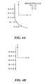
- the polar coordinate system or the spherical coordinate systeminvolves the distance from the origin 0 and two angles ⁇ and ⁇ as shown in FIG. 3 .
- the originis typically determined, at least initially, via the fix subsystem described above.
- the range of ⁇is from 0 to 2 ⁇ (360), and the range of ⁇ is from 0 to ⁇ (180°).
- the robotwill typically include a three-dimensional map of the hull stored in memory 74 , FIG. 2 .
- the robotwill start at a calibration fix point P f (X n , Y n , Z n ), FIG. 3 .
- P fX n , Y n , Z n
- the robottravels according to a pre-programmed course.
- sensing subsystem 66measures ⁇ and ⁇ .
- Odometer 82measures r. This measured data is compared to the programmed position input by the user, e.g., the desired path of travel for the robot.
- P program (r, ⁇ , ⁇ )is the location where the robot is supposed to be according to the inputted desired path of travel and P measured (r, ⁇ , ⁇ ) is the actual measured location both referenced from the same starting point (X n , Y n , Z n ).
- the course correction equationcan also be represented in Cartesian coordinates.
- Removing the platform's angular motioncan be accomplished in a variety of ways.
- One wayis to stop the robot and measure this angular movement and store it. Once the robot begins moving again, the unwanted angular motion can be subtracted.
- Another wayis to include a multi-axis sensing system 70 located on the moving platform used to continuously measure the platform's angular motion and remotely provide this information to the robot as shown in FIG. 2 .
- Processor 62can then subtract the unwanted angular motion before it calculates a course correction. In either case, the subtraction can be accomplished by three-dimensional vector subtraction.
- multi-axis sensing system 66FIG. 2 is measuring angular rotation about each axis and the angular information is translated into ⁇ and ⁇ .
- Xis always zero
- ⁇90°
- the angle ⁇0° as long as Y is zero (0).
- ⁇will vary between 0 and 90°.
- the measured datais derived from the equations (1)-(3) above where, ⁇ and ⁇ are provided by multi-axis sensing system 66 and r is provided by odometer 22 .
- the ship's motionwill cause multi-axis sensing system 66 , FIG. 2 onboard the robot to report both the motion of both the robot and ship. To maintain the robot's navigation accuracy, the ship's motion needs to be accounted for and removed.
- a multi-axis sensing system 70If a multi-axis sensing system 70 , is placed on the ship, as the ship pitches, rolls and yaws, the multi-axis sensing system will measure the angular rotation about each axis in degrees per second. This information can then be transmitted to the robot as shown in FIG. 2 (for example when the robot receives fix data) where it will be accounted for and removed from the reported angular rotation onboard the robot.
- ship's motion as stated aboveis: X -axis 0.1°/sec, Y -axis 0.01°/sec, Z -axis 0°/sec, (13) and would be zeroed or calibrated out of the robot's navigation measurement system.
- FIG. 6depicts the operation of an exemplary subsystem.
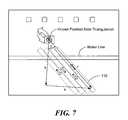
- the robotis at position Y N , X N on the ship's hull, typically above the water line, and transmitters 100 a and 100 b are fixed at known locations on the ship's hull.
- the distance A between transmitters 100 a and 100 bis a known value.
- Distances b and dare determined by the following calculations.
- the distance ais X3 ⁇ X1
- a frequency toneis emitted from the robot from transmitter 73 , FIG. 2 onboard the robot causing the frequency sources on the hull to each transmit a unique frequency at known locations on the hull.
- Radio triangulationis then used to more accurately determine where the robot is on the hull.
- the robot's known (calibrated) position fixis then the starting point of a stored pre-programmed cleaning path.
- sensor 66 , FIG. 2 and odometer 82continually measure the robot's location using the algorithm discussed above. This process is repeated as the robot travels from bow to stern according to the cleaning path depicted in FIG. 7 at 110 .
- FIG. 8shows ship's vessel motion data at 120 (based on, for example, sensing subsystem 70 , FIG. 2 ) subtracted from robot motion data as shown at 122 (also including ship motion data as discussed above for the output from sensor subsystem 66 , FIG. 2 .
- the robot's measured positionis shown at 126 in FIG. 8 .
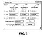
- FIG. 9shows the typical output of both sensor subsystems 66 and 70 , FIG. 2 , in this example, the rotation rate 127 for all three axes, and the acceleration 128 , and angle 129 for all three axes.
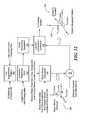
- the data from the navigation transmitters 100 on the vessel hull, and data from the angular sensor and the acceleration sensor onboard the ship's hullare combined as shown at 130 , FIG. 10 and transmitted via transmitter 140 .
- Receiver 72 and transmitter 73 onboard the robot(or alternatively a transmitter/receiver combination or transceiver) provides this data to navigation processor 62 .
- Data from sensor subsystem 66 and odometer 82is used by navigation processor 62 in addition to the ship hull mapping data and the intended programmed path of the robot as shown at 74 in order to control drive/steering subsystem the drive/steering subsystem.
- navigation processor 62includes determining a pre-programmed cleaning or inspection pattern, step 150 , FIG. 12 based on data stored in memory 74 as well as a user determined path also stored in memory 74 .
- a calibration reference point as shown at step 152is determined based on the triangulation technique described above.
- Navigation processor 63controls the drive subsystem to navigate the robot based on dead reckoning step 152 .
- the ship's motionis subtracted from the onboard sensor subsystem output data and, with the vessel's motion removed, in combination of the distance traveled as measured via odometer 82 , navigation processor 62 at step 158 determines the robot's location and provides course corrections as needed to a drive subsystem.
Landscapes
- Engineering & Computer Science (AREA)
- Radar, Positioning & Navigation (AREA)
- Remote Sensing (AREA)
- General Physics & Mathematics (AREA)
- Automation & Control Theory (AREA)
- Physics & Mathematics (AREA)
- Aviation & Aerospace Engineering (AREA)
- Mechanical Engineering (AREA)
- Ocean & Marine Engineering (AREA)
- Combustion & Propulsion (AREA)
- Chemical & Material Sciences (AREA)
- Robotics (AREA)
- Control Of Position, Course, Altitude, Or Attitude Of Moving Bodies (AREA)
Abstract
Description
X1=rsin θ cos φ (1)
Y1=rsin θ sin φ (2)
Z1=rcos θ (3)
r=(X12+Y12+Z12)1/2 (4)
θ=tan−1(Z1/(X12+Y12)1/2), and (5)
φ=tan−1(Y1/X1). (6)
Pprogram(r,Φ,θ)−Pmeasured(r,Φ,θ)=course correction(r,Φ,θ) (7)
Pprogram(r, Φ, θ) is the location where the robot is supposed to be according to the inputted desired path of travel and Pmeasured(r, Φ, θ) is the actual measured location both referenced from the same starting point (Xn, Yn, Zn). With the transformation equations above, the course correction equation can also be represented in Cartesian coordinates.
(x,y,z)program−(x,y,z)measured=0 (8)
or
Pprogram(r,Φ,θ)−Pmeasured(r,Φ,θ)=0. (9)
X-axis 0.1°/sec,Y-axis 0.01°/sec,Z-
the robot's speed and course and at a given point should have the angular rotation:
X-axis 0.0°/sec,Y-axis 0.05°/sec,Z-
In this example, assuming the angular motion of the ship and robot is in the same direction, then the combined angular motion measured by the robot is:
X-axis 0.1°/sec,Y-axis 0.06°/sec,Z-
The ships motion would then be subtracted resulting in the desired angular motion shown in equation (11).
X-axis 0.1°/sec,Y-axis 0.01°/sec,Z-
and would be zeroed or calibrated out of the robot's navigation measurement system.
The distance a is X3−X1
The distances b and d are determined by:
At time t=t0, frequency source F3T on board the robot transmits,
At time t=t0+t1F1R, F1R receives F3T signal and
At time t=t0+t1F2R, F2R receives F3T signal,
At time t=t0+t1F1R+t2F1T, F1T transmits a signal and
At time t=t0+t1F2R+t2F2T, F2T transmits a signal,
At time t=t0+t1F1R+t2F1T+t2F3R, F3R receives F1T signal and
At time t=t0+t1F2Rt2F2Tt2F3R, F3R receives F2T signal
Therefore,
b=[(t0+t1F1R+t2F1T+t2F3R))/2]c, and d=[(t0+t1F2R+t2F2T+t2F3R)/2]c
C=speed of light
Claims (22)
Priority Applications (8)
| Application Number | Priority Date | Filing Date | Title |
|---|---|---|---|
| US12/800,486US8386112B2 (en) | 2010-05-17 | 2010-05-17 | Vessel hull robot navigation subsystem |
| CN201180031384.8ACN103003143B (en) | 2010-05-17 | 2011-05-05 | Vessel hull robot navigation subsystem |
| KR1020127031668AKR101597393B1 (en) | 2010-05-17 | 2011-05-05 | Vessel hull robot navigation subsystem |
| EP11783852.4AEP2571755A4 (en) | 2010-05-17 | 2011-05-05 | Vessel hull robot navigation subsystem |
| JP2013511143AJP5774684B2 (en) | 2010-05-17 | 2011-05-05 | Ship shell robot navigation subsystem |
| AU2011256820AAU2011256820B2 (en) | 2010-05-17 | 2011-05-05 | Vessel hull robot navigation subsystem |
| PCT/US2011/000787WO2011146103A1 (en) | 2010-05-17 | 2011-05-05 | Vessel hull robot navigation subsystem |
| TW100117268ATWI424939B (en) | 2010-05-17 | 2011-05-17 | Vessel hull robot navigation subsystem |
Applications Claiming Priority (1)
| Application Number | Priority Date | Filing Date | Title |
|---|---|---|---|
| US12/800,486US8386112B2 (en) | 2010-05-17 | 2010-05-17 | Vessel hull robot navigation subsystem |
Publications (2)
| Publication Number | Publication Date |
|---|---|
| US20110282536A1 US20110282536A1 (en) | 2011-11-17 |
| US8386112B2true US8386112B2 (en) | 2013-02-26 |
Family
ID=44912475
Family Applications (1)
| Application Number | Title | Priority Date | Filing Date |
|---|---|---|---|
| US12/800,486Active2031-02-01US8386112B2 (en) | 2010-05-17 | 2010-05-17 | Vessel hull robot navigation subsystem |
Country Status (8)
| Country | Link |
|---|---|
| US (1) | US8386112B2 (en) |
| EP (1) | EP2571755A4 (en) |
| JP (1) | JP5774684B2 (en) |
| KR (1) | KR101597393B1 (en) |
| CN (1) | CN103003143B (en) |
| AU (1) | AU2011256820B2 (en) |
| TW (1) | TWI424939B (en) |
| WO (1) | WO2011146103A1 (en) |
Cited By (10)
| Publication number | Priority date | Publication date | Assignee | Title |
|---|---|---|---|---|
| US20100126403A1 (en)* | 2008-11-21 | 2010-05-27 | Rooney Iii James H | Hull Robot |
| US20100131098A1 (en)* | 2008-11-21 | 2010-05-27 | Rooney Iii James H | Hull robot with rotatable turret |
| US20140081504A1 (en)* | 2012-09-14 | 2014-03-20 | Raytheon Company | Autonomous Hull Navigation |
| US9233724B2 (en) | 2009-10-14 | 2016-01-12 | Raytheon Company | Hull robot drive system |
| WO2017053136A1 (en) | 2015-09-22 | 2017-03-30 | Sanuwave, Inc. | Cleaning and grooming water submerged structures using acoustic pressure shock waves |
| US10160406B2 (en)* | 2016-03-22 | 2018-12-25 | Boe Technology Group Co., Ltd. | Mobile platform and operating method thereof |
| US20190248454A1 (en)* | 2016-06-17 | 2019-08-15 | CleanSubSea Operations Pty Ltd | A vessel hull cleaning system |
| US10583905B2 (en) | 2016-12-07 | 2020-03-10 | Abb Power Grids Switzerland Ag | Submersible drone having active ballast system |
| WO2022140830A1 (en)* | 2020-12-30 | 2022-07-07 | Petróleo Brasileiro S.A. - Petrobras | Integrated system for removing and treating marine biofouling on submerged metal surfaces |
| KR20240050551A (en) | 2022-10-11 | 2024-04-19 | 한국해양과학기술원 | Acoustic positioning aided underwater navigation system of in-water hull cleaning robot and method thereof |
Families Citing this family (17)
| Publication number | Priority date | Publication date | Assignee | Title |
|---|---|---|---|---|
| US8393286B2 (en)* | 2009-09-18 | 2013-03-12 | Raytheon Company | Hull robot garage |
| US8386112B2 (en)* | 2010-05-17 | 2013-02-26 | Raytheon Company | Vessel hull robot navigation subsystem |
| US8800628B2 (en) | 2012-05-23 | 2014-08-12 | Lockheed Martin Corporation | Self-propelled airship hull repair system |
| CN102700692B (en)* | 2012-06-19 | 2015-06-10 | 江苏大学 | Underwater real-time surface dirt cleaning and detecting device for optical-fiber laser |
| KR101487681B1 (en)* | 2013-09-26 | 2015-01-29 | 삼성중공업 주식회사 | Apparatus for guide moving path of robot |
| KR101516545B1 (en)* | 2013-10-31 | 2015-05-04 | 삼성중공업 주식회사 | Apparatus for displaying photographing image of robot |
| WO2015081136A1 (en)* | 2013-11-30 | 2015-06-04 | Saudi Arabian Oil Company | System and method for calculating the orientation of a device |
| US9629774B2 (en)* | 2014-01-14 | 2017-04-25 | Toyota Motor Engineering & Manufacturing North America, Inc. | Smart necklace with stereo vision and onboard processing |
| CN108423141B (en)* | 2018-02-05 | 2020-03-31 | 浙江大学 | An underwater working robot and its control method |
| GB201803700D0 (en) | 2018-03-08 | 2018-04-25 | Jotun As | Device |
| GB2582955B (en)* | 2019-04-10 | 2023-02-08 | Jotun As | Monitoring module |
| GB2582954B (en)* | 2019-04-10 | 2022-10-19 | Jotun As | Monitoring module |
| NO345712B1 (en) | 2019-05-10 | 2021-06-28 | Shipshave As | A robot and method for underwater monitoring and maintenance of a ship’s hull when the ship is underway |
| US20220324543A1 (en)* | 2019-08-09 | 2022-10-13 | Hullbot Pty Ltd | Systems for cleaning underwater structures |
| EP3838736A1 (en)* | 2019-12-18 | 2021-06-23 | John Derek Townson | Anti-fouling robot |
| CN113110531B (en)* | 2021-04-19 | 2021-11-12 | 飞马滨(青岛)智能科技有限公司 | Automatic wall-adhering method for underwater robot and ship to be washed |
| CN120503650B (en)* | 2025-07-21 | 2025-10-03 | 时代天海科技有限公司 | Remote control real-time data transmission and feedback method for automatic charging robot |
Citations (89)
| Publication number | Priority date | Publication date | Assignee | Title |
|---|---|---|---|---|
| US2104062A (en) | 1935-10-28 | 1938-01-04 | John C Temple | Surfacing machine |
| US2132661A (en) | 1935-11-29 | 1938-10-11 | John C Temple | Surfacing machine |
| US2386650A (en) | 1943-03-11 | 1945-10-09 | Leroy V Bell | Mother ship |
| US3088429A (en) | 1961-06-28 | 1963-05-07 | Johannessen Harry De Fi Brandt | Cleaning devices for removing marine growth from ships' hulls |
| US3285676A (en) | 1964-10-28 | 1966-11-15 | Polaris Inc | Rubber track |
| US3439937A (en) | 1965-09-30 | 1969-04-22 | Secr Defence Brit | Articulated vehicles |
| US3554300A (en) | 1969-05-28 | 1971-01-12 | Edgar N Rosenberg | Deep submergence tunneling device |
| US3638600A (en) | 1969-08-21 | 1972-02-01 | Henry J Modrey | Apparatus for treating ferrous surfaces |
| US3777834A (en) | 1969-05-16 | 1973-12-11 | Hitachi Metals Ltd | Magnet vehicle |
| US3922991A (en) | 1973-06-25 | 1975-12-02 | John W Woods | Apparatus for cleaning metallic surfaces |
| US3934664A (en) | 1973-02-01 | 1976-01-27 | Pohjola Jorma | Steering mechanism for track vehicles |
| US3946692A (en) | 1973-12-28 | 1976-03-30 | Phoceenne Sous Marine - Psm Les Hommes Grenouilies Du Port De Marseille | Device for cleaning ship's hulls and other immersed surfaces |
| US3960229A (en) | 1975-03-31 | 1976-06-01 | Cheng Shio | Electromagnetic vehicle |
| US3984944A (en) | 1974-06-21 | 1976-10-12 | Wolfgang Maasberg | Device for cleaning ship's sides, tank walls, and similar surfaces |
| US4046429A (en) | 1973-02-01 | 1977-09-06 | Pohjola Jorma | Steering mechanism for endless track vehicles |
| US4079694A (en) | 1975-12-01 | 1978-03-21 | Commissariat A L'energie Atomique | Apparatus for applying a coating to a submerged surface |
| US4119356A (en) | 1975-02-10 | 1978-10-10 | Pohjola Jorma | Vehicle and endless track structure therefor |
| US4135592A (en) | 1976-06-18 | 1979-01-23 | Trelleborgs Gummifabriks Aktiebolag | Four-wheel-drive articulated frame steering vehicle |
| US4202453A (en) | 1978-01-05 | 1980-05-13 | Timberline, Inc. | Articulated mine service vehicle |
| GB2038721A (en) | 1978-12-01 | 1980-07-30 | Bingham V P | Apparatus for cleaning ship's hulls |
| US4251791A (en) | 1978-12-08 | 1981-02-17 | Kanetsu Kogyo Kabushiki Kaisha | Magnetic base |
| US4401048A (en) | 1982-03-17 | 1983-08-30 | Rogers Robert C | Portable boat hull scrubber |
| US4574722A (en) | 1982-10-06 | 1986-03-11 | Mitsui Engineering & Shipbuilding Co., Ltd. | Underwater cleaning apparatus |
| US4674949A (en) | 1982-01-11 | 1987-06-23 | International Robotic Engineering, Inc. | Robot with climbing feet |
| US4690092A (en) | 1986-06-05 | 1987-09-01 | Milton Rabuse | Aquatic scrubbing device |
| US4697536A (en) | 1984-02-27 | 1987-10-06 | West Tsusho Co., Ltd. | Underwater cleaning apparatus |
| DE3611750A1 (en) | 1986-04-08 | 1987-10-22 | Braun Jean | Devices to make use of kinetic primary energy |
| US4734954A (en) | 1987-02-24 | 1988-04-05 | Paul Greskovics | Pool scrubber device |
| US4736826A (en) | 1985-04-22 | 1988-04-12 | Remote Technology Corporation | Remotely controlled and/or powered mobile robot with cable management arrangement |
| US4789037A (en) | 1986-06-03 | 1988-12-06 | Remotely Operated Vehicles Limited | Self-propelled vehicle |
| US4809383A (en) | 1985-02-25 | 1989-03-07 | Uragami Fukashi | Device capable of adhering to a wall surface by suction and treating it |
| US4841894A (en) | 1988-03-02 | 1989-06-27 | Nellessen Jr Peter | Hull cleaner |
| US4890567A (en) | 1987-12-01 | 1990-01-02 | Caduff Edward A | Robotic ultrasonic cleaning and spraying device for ships' hulls |
| US4926775A (en) | 1986-08-21 | 1990-05-22 | Andorsen John P | Device for cleaning surfaces, particularly in water |
| US5048445A (en) | 1989-09-08 | 1991-09-17 | Cavi-Tech, Inc. | Fluid jet system and method for underwater maintenance of ship performance |
| US5174222A (en) | 1991-11-04 | 1992-12-29 | Rogers Mark C | Apparatus for cleaning of ship hulls |
| US5203646A (en) | 1992-02-06 | 1993-04-20 | Cornell Research Foundation, Inc. | Cable crawling underwater inspection and cleaning robot |
| US5249631A (en) | 1989-05-24 | 1993-10-05 | Bran Ferren | Water powered mobile robot |
| US5253724A (en) | 1991-10-25 | 1993-10-19 | Prior Ronald E | Power wheelchair with transmission using multiple motors per drive wheel |
| US5253605A (en) | 1992-12-21 | 1993-10-19 | Applied Remote Technology, Inc. | Method and apparatus for deploying and recovering water borne vehicles |
| US5285601A (en) | 1991-12-31 | 1994-02-15 | The Wheelabrator Corporation | Magnetic track self-propelled blast cleaning machine |
| US5366038A (en) | 1992-08-25 | 1994-11-22 | Nishiguchi Hidetsugu | Robot traveling on wall face |
| US5435405A (en) | 1993-05-14 | 1995-07-25 | Carnegie Mellon University | Reconfigurable mobile vehicle with magnetic tracks |
| US5628271A (en) | 1995-03-22 | 1997-05-13 | Amclean, Inc. | Apparatus and method for removing coatings from the hulls of vessels using ultra-high pressure water |
| US5849099A (en) | 1995-01-18 | 1998-12-15 | Mcguire; Dennis | Method for removing coatings from the hulls of vessels using ultra-high pressure water |
| US5852984A (en) | 1996-01-31 | 1998-12-29 | Ishikawajimi-Harima Heavy Industries Co., Ltd. | Underwater vehicle and method of positioning same |
| US5894901A (en) | 1995-12-12 | 1999-04-20 | Babcock-Hitachi Kabushiki Kaisha | Endless track magnetic traveling device |
| US5947051A (en) | 1997-06-04 | 1999-09-07 | Geiger; Michael B. | Underwater self-propelled surface adhering robotically operated vehicle |
| US6000484A (en) | 1996-09-25 | 1999-12-14 | Aqua Dynamics, Inc. | Articulating wheeled permanent magnet chassis with high pressure sprayer |
| US6053267A (en) | 1998-06-25 | 2000-04-25 | Technical Mechanical Resource Associates, Inc. | Coating removal vehicle with inflatable suction ring |
| US6064708A (en) | 1997-07-17 | 2000-05-16 | Kabushiki Kaisha Toshiba | Underwater inspection/repair apparatus |
| US6102145A (en) | 1998-06-25 | 2000-08-15 | Technical Mechanical Resource Associates, Inc. | Coating removal vehicle with resilient suction ring |
| US6125955A (en) | 1999-03-11 | 2000-10-03 | Aqua Dynamics, Inc. | Magnetic wheel |
| US6317387B1 (en) | 1997-11-20 | 2001-11-13 | D'amaddio Eugene R. | Method and apparatus for inspecting a submerged structure |
| WO2002074611A2 (en) | 2001-03-16 | 2002-09-26 | Ultrastrip Systems, Inc. | Air gap magnetic mobile robot |
| US20030000445A1 (en) | 1995-03-22 | 2003-01-02 | Mcguire Dennis | Apparatus and method for removingcpatomgs from the hulls of vessels using ultra-high pressure water |
| US6698376B2 (en) | 2001-04-13 | 2004-03-02 | Societe Eca | Device for launching and recovering an underwater vehicle and implementation method |
| US20040089216A1 (en) | 2001-05-30 | 2004-05-13 | Van Rompay Boudewijn Gabriel | Device for removing the growth on a ship's hull |
| US20040133999A1 (en) | 2003-01-13 | 2004-07-15 | Walton Charles A. | Underwater cleaning and scrubbing apparatus |
| US6792335B2 (en) | 2001-05-23 | 2004-09-14 | Carnegie Mellon University | Robotic apparatuses, systems and methods |
| US20050027412A1 (en) | 2003-05-19 | 2005-02-03 | Hobson Brett W. | Amphibious robot devices and related methods |
| WO2005014387A1 (en) | 2003-08-07 | 2005-02-17 | Company Ex As | Apparatus for cleaning the hull exterior of a seagoing vessel |
| US6886651B1 (en) | 2002-01-07 | 2005-05-03 | Massachusetts Institute Of Technology | Material transportation system |
| US20050156562A1 (en) | 2004-01-21 | 2005-07-21 | Irobot Corporation | Autonomous robot auto-docking and energy management systems and methods |
| US20050216125A1 (en) | 2004-03-15 | 2005-09-29 | University Of Vermont | Systems comprising a mechanically actuated magnetic on-off attachment device |
| US20060175439A1 (en) | 2005-02-08 | 2006-08-10 | Steur Gunnar V D | Voltage and turbine speed control apparatus for a rotary atomizer |
| US20060191457A1 (en)* | 2003-07-03 | 2006-08-31 | Murphy Robert J | Marine payload handling craft and system |
| US20060249622A1 (en) | 2005-05-04 | 2006-11-09 | Lockheed Martin Corporation | Autonomous Environmental Control System and Method For Post-Capture and Pre-Launch Management of an Unmanned Air Vehicle |
| US20060261772A1 (en) | 2005-05-17 | 2006-11-23 | Lg Electronics Inc. | Position-recognizing system for self-moving robot |
| US20070089916A1 (en) | 2003-11-14 | 2007-04-26 | Lundstroem Lennart | Electrically propulsed vehicle |
| US7296530B1 (en) | 2005-12-12 | 2007-11-20 | United States Of America As Represented By The Secretary Of The Navy | Unmanned system for underwater object inspection, identification and/or neutralization |
| US20070276552A1 (en) | 2006-02-24 | 2007-11-29 | Donald Rodocker | Underwater crawler vehicle having search and identification capabilities and methods of use |
| US20070284940A1 (en) | 2006-06-09 | 2007-12-13 | Hiran Koolhiran | Track Shoe Assembly for Tracked Vehicle |
| US7390560B2 (en) | 2004-04-02 | 2008-06-24 | Pel Associates | Smart coating systems |
| US20080202405A1 (en) | 2007-02-26 | 2008-08-28 | Physical Sciences, Inc. | Launch and Recovery Devices for Water Vehicles and Methods of Use |
| US20080276407A1 (en) | 2007-05-09 | 2008-11-13 | Irobot Corporation | Compact Autonomous Coverage Robot |
| US20090078484A1 (en) | 2006-03-13 | 2009-03-26 | Matswitch Technology Worldwide Pty Ltd | Magnetic wheel |
| US20090094765A1 (en) | 2006-03-14 | 2009-04-16 | Yanmar Co., Ltd. | Submersible cleaning robot |
| US7520356B2 (en) | 2006-04-07 | 2009-04-21 | Research Foundation Of The City University Of New York | Modular wall climbing robot with transition capability |
| US20090166102A1 (en) | 2007-12-20 | 2009-07-02 | Markus Waibel | Robotic locomotion method and mobile robot |
| US20090301203A1 (en) | 2005-04-28 | 2009-12-10 | Roboplanet | Tool, Sensor, and Device for a Wall Non-Distructive Control |
| US20100000723A1 (en) | 2006-02-23 | 2010-01-07 | Colin James Chambers | System, Method and Apparatus for Transferring Heat |
| US20100131098A1 (en) | 2008-11-21 | 2010-05-27 | Rooney Iii James H | Hull robot with rotatable turret |
| US20100126403A1 (en) | 2008-11-21 | 2010-05-27 | Rooney Iii James H | Hull Robot |
| US20100217436A1 (en) | 2009-02-24 | 2010-08-26 | Christopher Vernon Jones | Method and Device for Manipulating an Object |
| US20100219003A1 (en) | 2008-11-21 | 2010-09-02 | Rooney Iii James H | Hull robot steering system |
| US7866421B2 (en) | 2008-01-28 | 2011-01-11 | Siemens Energy, Inc. | Automated remote carriage for tightening generator wedges |
| US20110208417A1 (en)* | 2009-12-29 | 2011-08-25 | Research In Motion Limited | System and method of representing route information |
| US20110282536A1 (en)* | 2010-05-17 | 2011-11-17 | Rooney Iii James H | Vessel hull robot navigation subsystem |
Family Cites Families (6)
| Publication number | Priority date | Publication date | Assignee | Title |
|---|---|---|---|---|
| JPH1016884A (en)* | 1996-07-04 | 1998-01-20 | Penta Ocean Constr Co Ltd | Diving equipment for underwater floating structures |
| US6365221B1 (en)* | 1999-11-23 | 2002-04-02 | Visions East, Inc. | Computer controlled method and apparatus for fairing and painting of marine vessel surfaces |
| JP2003025265A (en)* | 2001-07-11 | 2003-01-29 | Mitsubishi Heavy Ind Ltd | Underwater robot operation support simulator |
| GB0515031D0 (en)* | 2005-07-22 | 2005-08-31 | Univ Newcastle | Apparatus for determining the position of a moveable apparatus on a surface |
| WO2009066272A1 (en)* | 2007-11-22 | 2009-05-28 | Poltak Sitinjak | Robotic phonton and automatic rubbish screening system, to clean up rubbishes floating into and out of waters zone |
| CN101436074B (en)* | 2008-12-06 | 2011-01-26 | 中国海洋大学 | Autonomous Underwater Robot Using Simultaneous Localization and Mapping Approach |
- 2010
- 2010-05-17USUS12/800,486patent/US8386112B2/enactiveActive
- 2011
- 2011-05-05KRKR1020127031668Apatent/KR101597393B1/enactiveActive
- 2011-05-05AUAU2011256820Apatent/AU2011256820B2/enactiveActive
- 2011-05-05WOPCT/US2011/000787patent/WO2011146103A1/enactiveApplication Filing
- 2011-05-05JPJP2013511143Apatent/JP5774684B2/enactiveActive
- 2011-05-05EPEP11783852.4Apatent/EP2571755A4/ennot_activeWithdrawn
- 2011-05-05CNCN201180031384.8Apatent/CN103003143B/enactiveActive
- 2011-05-17TWTW100117268Apatent/TWI424939B/enactive
Patent Citations (95)
| Publication number | Priority date | Publication date | Assignee | Title |
|---|---|---|---|---|
| US2104062A (en) | 1935-10-28 | 1938-01-04 | John C Temple | Surfacing machine |
| US2132661A (en) | 1935-11-29 | 1938-10-11 | John C Temple | Surfacing machine |
| US2386650A (en) | 1943-03-11 | 1945-10-09 | Leroy V Bell | Mother ship |
| US3088429A (en) | 1961-06-28 | 1963-05-07 | Johannessen Harry De Fi Brandt | Cleaning devices for removing marine growth from ships' hulls |
| US3285676A (en) | 1964-10-28 | 1966-11-15 | Polaris Inc | Rubber track |
| US3439937A (en) | 1965-09-30 | 1969-04-22 | Secr Defence Brit | Articulated vehicles |
| US3777834A (en) | 1969-05-16 | 1973-12-11 | Hitachi Metals Ltd | Magnet vehicle |
| US3554300A (en) | 1969-05-28 | 1971-01-12 | Edgar N Rosenberg | Deep submergence tunneling device |
| US3638600A (en) | 1969-08-21 | 1972-02-01 | Henry J Modrey | Apparatus for treating ferrous surfaces |
| US4046429A (en) | 1973-02-01 | 1977-09-06 | Pohjola Jorma | Steering mechanism for endless track vehicles |
| US3934664A (en) | 1973-02-01 | 1976-01-27 | Pohjola Jorma | Steering mechanism for track vehicles |
| US3922991A (en) | 1973-06-25 | 1975-12-02 | John W Woods | Apparatus for cleaning metallic surfaces |
| US3946692A (en) | 1973-12-28 | 1976-03-30 | Phoceenne Sous Marine - Psm Les Hommes Grenouilies Du Port De Marseille | Device for cleaning ship's hulls and other immersed surfaces |
| US3984944A (en) | 1974-06-21 | 1976-10-12 | Wolfgang Maasberg | Device for cleaning ship's sides, tank walls, and similar surfaces |
| US4119356A (en) | 1975-02-10 | 1978-10-10 | Pohjola Jorma | Vehicle and endless track structure therefor |
| US3960229A (en) | 1975-03-31 | 1976-06-01 | Cheng Shio | Electromagnetic vehicle |
| US4079694A (en) | 1975-12-01 | 1978-03-21 | Commissariat A L'energie Atomique | Apparatus for applying a coating to a submerged surface |
| US4135592A (en) | 1976-06-18 | 1979-01-23 | Trelleborgs Gummifabriks Aktiebolag | Four-wheel-drive articulated frame steering vehicle |
| US4202453A (en) | 1978-01-05 | 1980-05-13 | Timberline, Inc. | Articulated mine service vehicle |
| GB2038721A (en) | 1978-12-01 | 1980-07-30 | Bingham V P | Apparatus for cleaning ship's hulls |
| US4251791A (en) | 1978-12-08 | 1981-02-17 | Kanetsu Kogyo Kabushiki Kaisha | Magnetic base |
| US4674949A (en) | 1982-01-11 | 1987-06-23 | International Robotic Engineering, Inc. | Robot with climbing feet |
| US4401048A (en) | 1982-03-17 | 1983-08-30 | Rogers Robert C | Portable boat hull scrubber |
| US4574722A (en) | 1982-10-06 | 1986-03-11 | Mitsui Engineering & Shipbuilding Co., Ltd. | Underwater cleaning apparatus |
| US4697536A (en) | 1984-02-27 | 1987-10-06 | West Tsusho Co., Ltd. | Underwater cleaning apparatus |
| US4809383A (en) | 1985-02-25 | 1989-03-07 | Uragami Fukashi | Device capable of adhering to a wall surface by suction and treating it |
| US4736826A (en) | 1985-04-22 | 1988-04-12 | Remote Technology Corporation | Remotely controlled and/or powered mobile robot with cable management arrangement |
| DE3611750A1 (en) | 1986-04-08 | 1987-10-22 | Braun Jean | Devices to make use of kinetic primary energy |
| US4789037A (en) | 1986-06-03 | 1988-12-06 | Remotely Operated Vehicles Limited | Self-propelled vehicle |
| US4690092A (en) | 1986-06-05 | 1987-09-01 | Milton Rabuse | Aquatic scrubbing device |
| US4926775A (en) | 1986-08-21 | 1990-05-22 | Andorsen John P | Device for cleaning surfaces, particularly in water |
| US4734954A (en) | 1987-02-24 | 1988-04-05 | Paul Greskovics | Pool scrubber device |
| US4890567A (en) | 1987-12-01 | 1990-01-02 | Caduff Edward A | Robotic ultrasonic cleaning and spraying device for ships' hulls |
| US4841894A (en) | 1988-03-02 | 1989-06-27 | Nellessen Jr Peter | Hull cleaner |
| US5249631A (en) | 1989-05-24 | 1993-10-05 | Bran Ferren | Water powered mobile robot |
| US5048445A (en) | 1989-09-08 | 1991-09-17 | Cavi-Tech, Inc. | Fluid jet system and method for underwater maintenance of ship performance |
| US5253724A (en) | 1991-10-25 | 1993-10-19 | Prior Ronald E | Power wheelchair with transmission using multiple motors per drive wheel |
| US5174222A (en) | 1991-11-04 | 1992-12-29 | Rogers Mark C | Apparatus for cleaning of ship hulls |
| US5285601A (en) | 1991-12-31 | 1994-02-15 | The Wheelabrator Corporation | Magnetic track self-propelled blast cleaning machine |
| US5203646A (en) | 1992-02-06 | 1993-04-20 | Cornell Research Foundation, Inc. | Cable crawling underwater inspection and cleaning robot |
| US5366038A (en) | 1992-08-25 | 1994-11-22 | Nishiguchi Hidetsugu | Robot traveling on wall face |
| US5253605A (en) | 1992-12-21 | 1993-10-19 | Applied Remote Technology, Inc. | Method and apparatus for deploying and recovering water borne vehicles |
| US5435405A (en) | 1993-05-14 | 1995-07-25 | Carnegie Mellon University | Reconfigurable mobile vehicle with magnetic tracks |
| US5849099A (en) | 1995-01-18 | 1998-12-15 | Mcguire; Dennis | Method for removing coatings from the hulls of vessels using ultra-high pressure water |
| US5628271A (en) | 1995-03-22 | 1997-05-13 | Amclean, Inc. | Apparatus and method for removing coatings from the hulls of vessels using ultra-high pressure water |
| US20030000445A1 (en) | 1995-03-22 | 2003-01-02 | Mcguire Dennis | Apparatus and method for removingcpatomgs from the hulls of vessels using ultra-high pressure water |
| US6595152B2 (en) | 1995-03-22 | 2003-07-22 | Ultrastrip Systems, Inc. | Apparatus and method for removing coatings from the hulls of vessels using ultra-high pressure water |
| US5894901A (en) | 1995-12-12 | 1999-04-20 | Babcock-Hitachi Kabushiki Kaisha | Endless track magnetic traveling device |
| US5852984A (en) | 1996-01-31 | 1998-12-29 | Ishikawajimi-Harima Heavy Industries Co., Ltd. | Underwater vehicle and method of positioning same |
| US6000484A (en) | 1996-09-25 | 1999-12-14 | Aqua Dynamics, Inc. | Articulating wheeled permanent magnet chassis with high pressure sprayer |
| US5947051A (en) | 1997-06-04 | 1999-09-07 | Geiger; Michael B. | Underwater self-propelled surface adhering robotically operated vehicle |
| US6064708A (en) | 1997-07-17 | 2000-05-16 | Kabushiki Kaisha Toshiba | Underwater inspection/repair apparatus |
| US6317387B1 (en) | 1997-11-20 | 2001-11-13 | D'amaddio Eugene R. | Method and apparatus for inspecting a submerged structure |
| US6102145A (en) | 1998-06-25 | 2000-08-15 | Technical Mechanical Resource Associates, Inc. | Coating removal vehicle with resilient suction ring |
| US6053267A (en) | 1998-06-25 | 2000-04-25 | Technical Mechanical Resource Associates, Inc. | Coating removal vehicle with inflatable suction ring |
| US6125955A (en) | 1999-03-11 | 2000-10-03 | Aqua Dynamics, Inc. | Magnetic wheel |
| WO2002074611A3 (en) | 2001-03-16 | 2002-12-27 | Ultrastrip Systems Inc | Air gap magnetic mobile robot |
| US6564815B2 (en) | 2001-03-16 | 2003-05-20 | Ultrastrip Systems, Inc. | Air gap magnetic mobile robot |
| WO2002074611A2 (en) | 2001-03-16 | 2002-09-26 | Ultrastrip Systems, Inc. | Air gap magnetic mobile robot |
| US6698376B2 (en) | 2001-04-13 | 2004-03-02 | Societe Eca | Device for launching and recovering an underwater vehicle and implementation method |
| US6792335B2 (en) | 2001-05-23 | 2004-09-14 | Carnegie Mellon University | Robotic apparatuses, systems and methods |
| US20040089216A1 (en) | 2001-05-30 | 2004-05-13 | Van Rompay Boudewijn Gabriel | Device for removing the growth on a ship's hull |
| US6886486B2 (en) | 2001-05-30 | 2005-05-03 | Van Rompay Boudewijn Gabriel | Device for removing the growth on a ship's hull |
| US6886651B1 (en) | 2002-01-07 | 2005-05-03 | Massachusetts Institute Of Technology | Material transportation system |
| US20040133999A1 (en) | 2003-01-13 | 2004-07-15 | Walton Charles A. | Underwater cleaning and scrubbing apparatus |
| US20050027412A1 (en) | 2003-05-19 | 2005-02-03 | Hobson Brett W. | Amphibious robot devices and related methods |
| US20060191457A1 (en)* | 2003-07-03 | 2006-08-31 | Murphy Robert J | Marine payload handling craft and system |
| WO2005014387A1 (en) | 2003-08-07 | 2005-02-17 | Company Ex As | Apparatus for cleaning the hull exterior of a seagoing vessel |
| US20070089916A1 (en) | 2003-11-14 | 2007-04-26 | Lundstroem Lennart | Electrically propulsed vehicle |
| US20050156562A1 (en) | 2004-01-21 | 2005-07-21 | Irobot Corporation | Autonomous robot auto-docking and energy management systems and methods |
| US20050216125A1 (en) | 2004-03-15 | 2005-09-29 | University Of Vermont | Systems comprising a mechanically actuated magnetic on-off attachment device |
| US7390560B2 (en) | 2004-04-02 | 2008-06-24 | Pel Associates | Smart coating systems |
| US20060175439A1 (en) | 2005-02-08 | 2006-08-10 | Steur Gunnar V D | Voltage and turbine speed control apparatus for a rotary atomizer |
| US20090301203A1 (en) | 2005-04-28 | 2009-12-10 | Roboplanet | Tool, Sensor, and Device for a Wall Non-Distructive Control |
| US20060249622A1 (en) | 2005-05-04 | 2006-11-09 | Lockheed Martin Corporation | Autonomous Environmental Control System and Method For Post-Capture and Pre-Launch Management of an Unmanned Air Vehicle |
| US20060261772A1 (en) | 2005-05-17 | 2006-11-23 | Lg Electronics Inc. | Position-recognizing system for self-moving robot |
| US7296530B1 (en) | 2005-12-12 | 2007-11-20 | United States Of America As Represented By The Secretary Of The Navy | Unmanned system for underwater object inspection, identification and/or neutralization |
| US20100000723A1 (en) | 2006-02-23 | 2010-01-07 | Colin James Chambers | System, Method and Apparatus for Transferring Heat |
| US20070276552A1 (en) | 2006-02-24 | 2007-11-29 | Donald Rodocker | Underwater crawler vehicle having search and identification capabilities and methods of use |
| US20090078484A1 (en) | 2006-03-13 | 2009-03-26 | Matswitch Technology Worldwide Pty Ltd | Magnetic wheel |
| US20090094765A1 (en) | 2006-03-14 | 2009-04-16 | Yanmar Co., Ltd. | Submersible cleaning robot |
| US7520356B2 (en) | 2006-04-07 | 2009-04-21 | Research Foundation Of The City University Of New York | Modular wall climbing robot with transition capability |
| US20070284940A1 (en) | 2006-06-09 | 2007-12-13 | Hiran Koolhiran | Track Shoe Assembly for Tracked Vehicle |
| US20080202405A1 (en) | 2007-02-26 | 2008-08-28 | Physical Sciences, Inc. | Launch and Recovery Devices for Water Vehicles and Methods of Use |
| US20080281470A1 (en) | 2007-05-09 | 2008-11-13 | Irobot Corporation | Autonomous coverage robot sensing |
| US20080276407A1 (en) | 2007-05-09 | 2008-11-13 | Irobot Corporation | Compact Autonomous Coverage Robot |
| US20090166102A1 (en) | 2007-12-20 | 2009-07-02 | Markus Waibel | Robotic locomotion method and mobile robot |
| US7934575B2 (en) | 2007-12-20 | 2011-05-03 | Markus Waibel | Robotic locomotion method and mobile robot |
| US7866421B2 (en) | 2008-01-28 | 2011-01-11 | Siemens Energy, Inc. | Automated remote carriage for tightening generator wedges |
| US20100131098A1 (en) | 2008-11-21 | 2010-05-27 | Rooney Iii James H | Hull robot with rotatable turret |
| US20100126403A1 (en) | 2008-11-21 | 2010-05-27 | Rooney Iii James H | Hull Robot |
| US20100219003A1 (en) | 2008-11-21 | 2010-09-02 | Rooney Iii James H | Hull robot steering system |
| US20100217436A1 (en) | 2009-02-24 | 2010-08-26 | Christopher Vernon Jones | Method and Device for Manipulating an Object |
| US20110208417A1 (en)* | 2009-12-29 | 2011-08-25 | Research In Motion Limited | System and method of representing route information |
| US20110282536A1 (en)* | 2010-05-17 | 2011-11-17 | Rooney Iii James H | Vessel hull robot navigation subsystem |
Non-Patent Citations (35)
| Title |
|---|
| A Copenhagen Climate Treaty, Version 1.0 Draft, A Proposal for a Copenhagen Agreement by Members of the NGO Community, published Jun. 2009, pp. 1-78 (80 pages total). |
| Anti-Fouling Systems, Focus on IMO, International Maritime Organization, UK, 2002, pp. 1-31. http://www.uscg.mil/hq/cg5/cg522/cg5224/docs/FOULING2003.pdf. |
| Borchardt, John, Grooming the Fleet, Mechanical Engineering, vol. 132/No. 4 Apr. 2010, pp. 33-35. |
| Fernandez, Linda, NAFTA and Member Country Strategies for Maritime Trade and Marine Invasive Species, Journal of Environmental Management 89, 2008, pp. 308-321. |
| Fu-cai et al., "The Design of Underwater Hull-Cleaning Robot," Journal of Marine Science and Application, vol. 3, No. 1, Jun. 2004, pp. 41-45. |
| HISMAR HISMAR News Report No. 2. 2008, http://hismar.ncl.ac.uk/public-docs/News-Reports/News%20Report%20No2-UNEW.pdf (4 pages). |
| HISMAR Hull Identification System for Maritime Autonomous Robots, http://hismar.ncl.ac.uk/public-docs/HISMAR-Poster.pdf (1 page). |
| Kohli, Nikita, Biofouling and Design of a Biomimetic Hull-Grooming Tool, Naval Surface Warfare Center Carderock Division, West Bethesda, MD, NSWCCD-CISD-2007/002, Ship Systems Integration & Design Department Technical Report, Sep. 2007, 38 pages total. |
| Lee Min Wai Serene and Koh Cheok Wei, "Design of a Remotely Operated Vehicle (ROV) for Underwater Ship Hull Cleaning," National University of Singapore, 2003, pp. 1-6. |
| MAN, B&W, Basic Principles of Ship Propulsion, Basics of Ship Propulsion, pp. 1-30, Apr. 2004. |
| Munk, Torben, Fuel Conservation Through Managing Hull Resistance, Motorship Propulsion Conference, Copenhagen, Apr. 26, 2006 pp. 1-10. |
| Preiser et al., Energy (Fuel) Conservation Through Underwater Removal and Control of Fouling on Hulls of Navy Ships, Naval Research and Development Center, Materials Department, Annapolis, Research and Development Report, Dec. 1975, 52 pgs. |
| Rosenhahn et al., Advanced Nanostructures for the Control of Biofouling: The FP 6 EU Integrated Project AMBIO, Biointerphases 3(1) Mar. 2008, published Feb. 21, 2008; pp. IR1-IR5. |
| RTI International, EnSys Energy & Systems, Inc., Navigistics Consulting; Global Trade and Fuels Assessment-Future Trends and Effects of Designating Requiring Clean Fuels in the Marine Sector: Task Order No. 1, Draft Report, RTI Project No. 0209701.001, Apr. 2006 (82 pages total). |
| S. Reed, A. Cormack, K. Hamilton, I. Tena Ruiz, and D. Lane. "Automatic Ship Hull Inspection using Unmanned Underwater Vehicles," Proceedings from the 7th International Symposium on Technology and the Mine Problem. Monterey, USA. May 2006 (10 pages). |
| Tallett, et al., Potential Marine Fuels Regulations: Impacts on Global Refining, Costs & Emissions, Joint IFQC & IPIECA Roundtable: Impacts of CO2 Emissions from Refining & Shipping, London, England Oct. 1, 2007, 17 pgs. |
| Townsin, R.L., The Ship Hull Fouling Penalty, Biofouling, Jan. 2003, vol. 19, (supplement), Jan. 1, 2003, pp. 9-15. |
| U.S. Appl. No. 12/313,643, filed Nov. 21, 2008; James H. Rooney III; office action dated Sep. 17, 2012. |
| U.S. Appl. No. 12/313,643, filed Nov. 21, 2008; James H. Rooney III; office action issued Apr. 13, 2012. |
| U.S. Appl. No. 12/583,346, filed Aug. 19, 2009; James H. Rooney III; office action dated Sep. 25, 2012. |
| U.S. Appl. No. 12/586,248, filed Sep. 18, 2009, Rooney III et al. |
| U.S. Appl. No. 12/586,248, filed Sep. 18, 2009; James H. Rooney III; office action issued May 24, 2012. |
| U.S. Appl. No. 12/587,949, filed Oct. 14, 2009, Komstein et al. |
| U.S. Appl. No. 12/587,949, filed Oct. 14, 2009; Howard R. Kornstein; notice of allowance dated Sep. 21, 2012. |
| U.S. Appl. No. 12/587,949, filed Oct. 14, 2009; Howard R. Kornstein; office action issued May 25, 2012. |
| U.S. Appl. No. 12/800,174, filed May 10, 2010; James H. Rooney, III; office action issued Feb. 24, 2012. |
| U.S. Appl. No. 12/800,174; dated May 10, 2010; James H. Rooney III; notice of allowance dated Aug. 17, 2012. |
| Vaganay, J., Elkins, M., Espositio, D., Oapos, Halloran, W., Hover, F., Kokko, M. Ship Hull Inspection with the HAUV: US Navy and NATO Demonstrations Results, OCEANS 2006, vol., Issue, Sep. 18-21, 2006, pp. 1-6. |
| Written Opinion of the International Searching Authority for PCT Application No. PCT/US2009/006122 mailed Feb. 3, 2010 (seven (7) pages). |
| Written Opinion of the International Searching Authority, International Application No. PCT/US2010/002163, Oct. 13, 2010, 5 pgs. (unnumbered). |
| Written Opinion of the International Searching Authority, International Application No. PCT/US2010/002164, Oct. 8, 2010, 5 pgs. (unnumbered). |
| Written Opinion of the International Searching Authority, International Application No. PCT/US2010/002693, Dec. 9, 2010, 8 pgs. (unnumbered). |
| Written Opinion of the International Searching Authority, International Application No. PCT/US2011/000770, Aug. 9, 2011, 5 pgs. (unnumbered). |
| Written Opinion of the International Searching Authority, International Application No. PCT/US2011/000787, Jul. 20, 2011, 7 pgs. (unnumbered). |
| Yuan, et al., The Design of Underwater Hull-Cleaning Robot, Journal of Marine Science and Application, vol. 3, No. 1, Jun. 2004, pp. 41-45. |
Cited By (17)
| Publication number | Priority date | Publication date | Assignee | Title |
|---|---|---|---|---|
| US20100131098A1 (en)* | 2008-11-21 | 2010-05-27 | Rooney Iii James H | Hull robot with rotatable turret |
| US9440717B2 (en) | 2008-11-21 | 2016-09-13 | Raytheon Company | Hull robot |
| US9254898B2 (en) | 2008-11-21 | 2016-02-09 | Raytheon Company | Hull robot with rotatable turret |
| US20100126403A1 (en)* | 2008-11-21 | 2010-05-27 | Rooney Iii James H | Hull Robot |
| US9233724B2 (en) | 2009-10-14 | 2016-01-12 | Raytheon Company | Hull robot drive system |
| US9051028B2 (en) | 2012-09-14 | 2015-06-09 | Raytheon Company | Autonomous hull inspection |
| US9180934B2 (en) | 2012-09-14 | 2015-11-10 | Raytheon Company | Hull cleaning robot |
| US9061736B2 (en) | 2012-09-14 | 2015-06-23 | Raytheon Company | Hull robot for autonomously detecting cleanliness of a hull |
| US9038557B2 (en) | 2012-09-14 | 2015-05-26 | Raytheon Company | Hull robot with hull separation countermeasures |
| US20140081504A1 (en)* | 2012-09-14 | 2014-03-20 | Raytheon Company | Autonomous Hull Navigation |
| WO2017053136A1 (en) | 2015-09-22 | 2017-03-30 | Sanuwave, Inc. | Cleaning and grooming water submerged structures using acoustic pressure shock waves |
| US10160406B2 (en)* | 2016-03-22 | 2018-12-25 | Boe Technology Group Co., Ltd. | Mobile platform and operating method thereof |
| US20190248454A1 (en)* | 2016-06-17 | 2019-08-15 | CleanSubSea Operations Pty Ltd | A vessel hull cleaning system |
| US11753123B2 (en) | 2016-06-17 | 2023-09-12 | CleanSubSea Operations Pty Ltd | Vessel hull cleaning system |
| US10583905B2 (en) | 2016-12-07 | 2020-03-10 | Abb Power Grids Switzerland Ag | Submersible drone having active ballast system |
| WO2022140830A1 (en)* | 2020-12-30 | 2022-07-07 | Petróleo Brasileiro S.A. - Petrobras | Integrated system for removing and treating marine biofouling on submerged metal surfaces |
| KR20240050551A (en) | 2022-10-11 | 2024-04-19 | 한국해양과학기술원 | Acoustic positioning aided underwater navigation system of in-water hull cleaning robot and method thereof |
Also Published As
| Publication number | Publication date |
|---|---|
| JP2013527074A (en) | 2013-06-27 |
| JP5774684B2 (en) | 2015-09-09 |
| WO2011146103A1 (en) | 2011-11-24 |
| US20110282536A1 (en) | 2011-11-17 |
| CN103003143A (en) | 2013-03-27 |
| EP2571755A4 (en) | 2014-08-27 |
| KR101597393B1 (en) | 2016-02-24 |
| AU2011256820B2 (en) | 2014-03-06 |
| TW201202092A (en) | 2012-01-16 |
| TWI424939B (en) | 2014-02-01 |
| AU2011256820A1 (en) | 2012-12-06 |
| CN103003143B (en) | 2015-12-09 |
| EP2571755A1 (en) | 2013-03-27 |
| KR20130027526A (en) | 2013-03-15 |
Similar Documents
| Publication | Publication Date | Title |
|---|---|---|
| US8386112B2 (en) | Vessel hull robot navigation subsystem | |
| Borenstein | Experimental results from internal odometry error correction with the OmniMate mobile robot | |
| US5764014A (en) | Automated guided vehicle having ground track sensor | |
| US20210271244A1 (en) | Indoor positioning and navigation systems and methods | |
| JP2007210402A (en) | Autonomous unmanned submersible and its underwater navigation method | |
| KR101291150B1 (en) | Ship hull working robot and control method the same | |
| JP2017512975A (en) | Modular mobile inspection vehicle | |
| JP5954241B2 (en) | Self-propelled inspection device and inspection method for metal plate | |
| US11525681B2 (en) | Method and apparatus for self-contained positioning of a mobile robot inside a tank | |
| CN109085597B (en) | Unmanned ship for underwater topography measurement | |
| KR20100061367A (en) | Unmanned boat automatic survey system and unmanned boat automatic survey method | |
| RU2446983C2 (en) | Underwater robotic complex | |
| RU2610149C1 (en) | Towed underwater vehicle, equipped with sonar equipment for detecting silting facilities and pipelines, and their subsequent monitoring | |
| Chen et al. | Design and climbing control of an underwater robot for ship hull cleaning | |
| EP4251496B1 (en) | Magnetic crawler with 3 articulated wheels for navigation on pipes | |
| JP2020169953A (en) | Method for calibrating inertia navigation device | |
| Hover et al. | A vehicle system for autonomous relative survey of in-water ships | |
| JP7668510B2 (en) | Self-position estimation error correction method and system for underwater vehicle | |
| RU2609618C1 (en) | Underwater robot system | |
| JP5381773B2 (en) | Position calibration method and apparatus for underwater vehicle | |
| Noguchi et al. | Wide area seafloor imaging by a low-cost AUV | |
| JPH0155356B2 (en) | ||
| JP2006248477A (en) | Underwater vehicle control method and underwater vehicle | |
| JP5381772B2 (en) | Position calibration method for underwater vehicle | |
| KR100652914B1 (en) | Vessel and Port Outer Wall Inspection System Using Unmanned Unmanned Submersible |
Legal Events
| Date | Code | Title | Description |
|---|---|---|---|
| AS | Assignment | Owner name:RAYTHEON COMPANY, MASSACHUSETTS Free format text:ASSIGNMENT OF ASSIGNORS INTEREST;ASSIGNOR:ROONEY, III JAMES H.;REEL/FRAME:024461/0601 Effective date:20100514 Owner name:RAYTHEON COMPANY, MASSACHUSETTS Free format text:ASSIGNMENT OF ASSIGNORS INTEREST;ASSIGNOR:ROONEY, III JAMES H.;REEL/FRAME:024666/0167 Effective date:20100514 | |
| AS | Assignment | Owner name:RAYTHEON COMPANY, MASSACHUSETTS Free format text:ASSIGNMENT OF ASSIGNORS INTEREST;ASSIGNORS:SMITH, FRASER;JACOBSEN, STEVEN C.;SIGNING DATES FROM 20110613 TO 20110623;REEL/FRAME:026533/0988 | |
| AS | Assignment | Owner name:RAYTHEON COMPANY, MASSACHUSETTS Free format text:CORRECTIVE ASSIGNMENT TO CORRECT THE NAME OF THE 2ND INVENTOR PREVIOUSLY RECORDED AT REEL 026533 FRAME 0988. THE ASSIGNOR HEREBY CONFIRMS THE ASSIGNMENT OF THE ENTIRE INTEREST;ASSIGNORS:SMITH, FRASER;JACOBSEN, STEPHEN C.;SIGNING DATES FROM 20110613 TO 20110623;REEL/FRAME:026661/0584 | |
| FEPP | Fee payment procedure | Free format text:PAYOR NUMBER ASSIGNED (ORIGINAL EVENT CODE: ASPN); ENTITY STATUS OF PATENT OWNER: LARGE ENTITY | |
| STCF | Information on status: patent grant | Free format text:PATENTED CASE | |
| FPAY | Fee payment | Year of fee payment:4 | |
| MAFP | Maintenance fee payment | Free format text:PAYMENT OF MAINTENANCE FEE, 8TH YEAR, LARGE ENTITY (ORIGINAL EVENT CODE: M1552); ENTITY STATUS OF PATENT OWNER: LARGE ENTITY Year of fee payment:8 | |
| MAFP | Maintenance fee payment | Free format text:PAYMENT OF MAINTENANCE FEE, 12TH YEAR, LARGE ENTITY (ORIGINAL EVENT CODE: M1553); ENTITY STATUS OF PATENT OWNER: LARGE ENTITY Year of fee payment:12 |