US8385992B2 - User interfaces and associated apparatus and methods - Google Patents
User interfaces and associated apparatus and methodsDownload PDFInfo
- Publication number
- US8385992B2 US8385992B2US12/339,386US33938608AUS8385992B2US 8385992 B2US8385992 B2US 8385992B2US 33938608 AUS33938608 AUS 33938608AUS 8385992 B2US8385992 B2US 8385992B2
- Authority
- US
- United States
- Prior art keywords
- user
- configuration
- interface
- output interface
- user input
- Prior art date
- Legal status (The legal status is an assumption and is not a legal conclusion. Google has not performed a legal analysis and makes no representation as to the accuracy of the status listed.)
- Expired - Fee Related, expires
Links
Images


Classifications
- H—ELECTRICITY
- H04—ELECTRIC COMMUNICATION TECHNIQUE
- H04M—TELEPHONIC COMMUNICATION
- H04M1/00—Substation equipment, e.g. for use by subscribers
- H04M1/02—Constructional features of telephone sets
- H04M1/0202—Portable telephone sets, e.g. cordless phones, mobile phones or bar type handsets
- H04M1/0206—Portable telephones comprising a plurality of mechanically joined movable body parts, e.g. hinged housings
- H04M1/0247—Portable telephones comprising a plurality of mechanically joined movable body parts, e.g. hinged housings comprising more than two body parts
- G—PHYSICS
- G06—COMPUTING OR CALCULATING; COUNTING
- G06F—ELECTRIC DIGITAL DATA PROCESSING
- G06F1/00—Details not covered by groups G06F3/00 - G06F13/00 and G06F21/00
- G06F1/16—Constructional details or arrangements
- G06F1/1613—Constructional details or arrangements for portable computers
- G06F1/1615—Constructional details or arrangements for portable computers with several enclosures having relative motions, each enclosure supporting at least one I/O or computing function
- G06F1/1624—Constructional details or arrangements for portable computers with several enclosures having relative motions, each enclosure supporting at least one I/O or computing function with sliding enclosures, e.g. sliding keyboard or display
- G—PHYSICS
- G06—COMPUTING OR CALCULATING; COUNTING
- G06F—ELECTRIC DIGITAL DATA PROCESSING
- G06F1/00—Details not covered by groups G06F3/00 - G06F13/00 and G06F21/00
- G06F1/16—Constructional details or arrangements
- G06F1/1613—Constructional details or arrangements for portable computers
- G06F1/1633—Constructional details or arrangements of portable computers not specific to the type of enclosures covered by groups G06F1/1615 - G06F1/1626
- G06F1/1675—Miscellaneous details related to the relative movement between the different enclosures or enclosure parts
- G06F1/1681—Details related solely to hinges
- H—ELECTRICITY
- H04—ELECTRIC COMMUNICATION TECHNIQUE
- H04M—TELEPHONIC COMMUNICATION
- H04M1/00—Substation equipment, e.g. for use by subscribers
- H04M1/02—Constructional features of telephone sets
- H04M1/0202—Portable telephone sets, e.g. cordless phones, mobile phones or bar type handsets
- H04M1/0206—Portable telephones comprising a plurality of mechanically joined movable body parts, e.g. hinged housings
- H04M1/0208—Portable telephones comprising a plurality of mechanically joined movable body parts, e.g. hinged housings characterized by the relative motions of the body parts
- H04M1/0235—Slidable or telescopic telephones, i.e. with a relative translation movement of the body parts; Telephones using a combination of translation and other relative motions of the body parts
- H04M1/0237—Sliding mechanism with one degree of freedom
Definitions
- the present disclosurerelates to the field of user interfaces, and more particularly, to apparatus having a plurality of user interfaces that are exposed when the apparatus is in different configurations, associated methods, computer program products and apparatus.
- Certain disclosed aspects/embodimentsrelate to portable electronic devices, in particular, so-called hand-portable electronic devices which may be hand-held in use (although they may be placed in a cradle in use).
- hand-portable electronic devicesinclude so-called Personal Digital Assistants (PDAs).
- PDAsPersonal Digital Assistants
- the portable electronic devices/apparatusmay provide one or more audio/text/video communication functions (e.g. telecommunication, video-communication, and/or text transmission (Short Message Service (SMS)/Multimedia Message Service (MMS)/emailing) functions), interactive/non-interactive viewing functions (e.g. web-browsing, navigation, TV/program viewing functions), music recording/playing functions (e.g. MP3 or other format and/or (FM/AM) radio broadcast recording/playing), downloading/sending of data functions, image capture function (e.g. using a (e.g. in-built) digital camera), and gaming functions.
- audio/text/video communication functionse.g. telecommunication, video-communication, and/or text transmission (Short Message Service (SMS)/Multimedia Message Service (MMS)/emailing) functions
- interactive/non-interactive viewing functionse.g. web-browsing, navigation, TV/program viewing functions
- music recording/playing functionse.
- Mobile telephonesinclude a top layer, a middle layer and a bottom layer that are slidably suspended from one another.
- the top layercan move between a retracted position in which a first keypad on the middle layer is covered and to a first extended position in which the first keypad is exposed.
- the top layercan also move to a second extended position in which a second keypad on the middle layer is exposed.
- WO 2007/140911Nokia Corporation
- apparatus for a portable electronic devicecomprising a base member, a user input interface, and a user output interface configured to extend along mutually perpendicular longitudinal and lateral axes of the apparatus, the user input interface comprising a QWERTY input configured to extend parallel to the longitudinal axis, the apparatus configured to provide a first configuration in which the user input interface is housed between the base member and the user output interface, and a second configuration in which the user input and output interfaces have been laterally slid in opposing directions with respect to the base member.
- the QWERTY inputmay be activated for use on the user input interface when the apparatus is in the second configuration, and may not be activated for use when the apparatus is in the first configuration. This can provide efficient use of overheads/resources, including power consumption as the user input interface may not use power when it is unavailable for use, for example when it is concealed from a user of the apparatus.
- apparatus for a portable electronic devicecomprising a base member, a user input interface and a user output interface, the user output interface configured to provide portrait and landscape modes of use, the apparatus configured to provide a first configuration in which the user input interface is housed between the base member and the user output interface with the user output interface providing the portrait mode of use, and a second configuration in which the user input and output interfaces have been slid in opposing directions with respect to the base member and the user output interface provides the landscape mode of use.
- the apparatusmay be economically sized and proportioned and still be capable of efficiently displaying information to a user and enabling a user to interact with the apparatus.
- the apparatusmay comprise mutually perpendicular longitudinal and lateral axes.
- the user input interfacemay comprise a QWERTY input configured to extend parallel to the longitudinal axis.
- the apparatusmay be configured such that, in the second configuration, the user input and output interfaces have been slid along the lateral axis.
- the QWERTY input of the user inputmay be for use with the landscape mode of use of the user output interface.
- the user output interfacemay be configured to align user output for viewing in an orientation in which the top of the user output is aligned with the longitudinal axis in the portrait mode of use.
- the user output interfacemay be configured to align user output for viewing in an orientation in which the top of the user output is aligned with the lateral axis in the landscape mode of use.
- the apparatusmay comprise a motion coupler coupled between the user input interface and the user output interface.
- the motion couplermay be configured to apply a force to the user input interface when an external force is applied to the user output interface to change the configuration of the apparatus.
- the force applied to the user input interfacemay be in the opposite direction to the force applied to the user output interface.
- the motion couplermay comprise one or more rack and pinion mechanisms.
- the one or more rack and pinion mechanismsmay be geared such that one of the user interfaces is configured to move faster than the other user interface.
- the motion couplermay comprise:
- the apparatusmay comprise two motion couplers, one on each side of the first and second parts.
- the user output interfacemay be configured to conceal all of the user input interface, or substantially all of the user input interface, when the apparatus is in the first configuration.
- All, or substantially all, of the user output interfacemay be exposed when the apparatus is in the first configuration.
- the base membermay also be known as a housing
- the user input interfacemay be associated with a first part of a device
- the user output interfacemay be associated with a second part of a device.
- the apparatusmay have three layers, a first layer comprising the base member/housing, a second layer comprising the user input interface/first part, and a third layer comprising the user output interface/second part.
- the first layermay be a bottom layer
- the second layermay be a middle layer
- the third layermay be a top layer.
- the top, middle and bottom locationsmay be defined in relation to the depth of the device when it is in an in-use orientation.
- the depth of the devicemay be considered as a Z direction, and the layers may be displaced relative to each other in the Z direction.
- the footprint of the base member, first part and second partmay all be of a similar size.
- the footprintmay be considered as the shape of a part in a lateral and longitudinal direction, which may also be known as the X and Y directions.
- Providing the base member, first part and second part with a similar footprintcan enable a mono-block form-factor to be achieved when the apparatus is in the first configuration.
- a mono-block form-factormay be a mechanically strong form-factor.
- Both the user input interface and the user output interfacemay overhang the base member when the apparatus is in the second configuration. Approximately half of the user input interface may overhang a first side of the base member when the apparatus is in the second configuration. Approximately half of the user output interface may overhang a second side of the base member when the apparatus is in the second configuration.
- all, or only part, of the area of user interfaces associated with an apparatuscan be exposed with a reduced travel of the first and second user interfaces relative to the base member. This can provide a mechanically strong/robust form-factor.
- the user output interfacemay be configured to provide portrait and landscape modes of use.
- the first configurationmay provide the portrait mode of use.
- the second configurationmay provide the landscape mode of use.
- the user input and output interfaceshave been slid along the lateral axis and the QWERTY input of the user input may be for use with the landscape mode of use of the user output interface.
- the user output interfacemay be configured to align user output for viewing in an orientation in which the top of the user output is aligned with the longitudinal axis in the portrait mode of use.
- the user output interfacemay be configured to align user output for viewing in an orientation in which the top of the user output is aligned with the lateral axis in the landscape mode of use.
- the user input interface and user output interfacemay be configured such that they can be tilted relative to each other to define a third configuration, wherein the third configuration is a further landscape mode of use. In some embodiments, in the third configuration, the user input interface and the user output interface may be exposed.
- the user input interfacemay be an input and output interface, and may comprise a touch sensitive screen.
- the user output interfacemay be an input and output interface, and may comprise a touch sensitive screen.
- apparatus for a portable electronic devicecomprising a base member, a user input interface, and a user output interface, the apparatus configured to provide a first configuration in which the user input interface is housed between the base member and the user output interface, and a second configuration in which the user input and output interfaces have been slid in opposing directions with respect to the base member to both overhang the base member.
- the apparatusmay comprise mutually perpendicular longitudinal and lateral axes, and in the second configuration, the user input and output interfaces have been slid along the lateral axis.
- the base membermay provide support for the user input and output interfaces in the second configuration.
- modulefor a device, the module comprising an apparatus disclosed herein.
- an apparatus for a portable electronic devicecomprising a base member means, a means for receiving user input, and a means for providing user output configured to extend along mutually perpendicular longitudinal and lateral axes of the apparatus, the means for receiving user input comprising a QWERTY input means configured to extend parallel to the longitudinal axis, the apparatus configured to provide a first configuration in which the means for receiving user input is housed between the base member means and the means for providing user output, and a second configuration in which the means for receiving user input and the means for providing user output have been laterally slid in opposing directions with respect to the base member means.
- an apparatuscomprising:
- the present disclosureincludes one or more corresponding aspects, embodiments or features in isolation or in various combinations whether or not specifically stated (including claimed) in that combination or in isolation.
- Corresponding means for performing one or more of the discussed functionsare also within the present disclosure.
- FIGS. 1 a - 1 cillustrate a device according to an embodiment of the invention
- FIGS. 2 a - 2 billustrate a device according to another embodiment of the invention
- FIGS. 3 a - 3 cillustrate a mechanism according to an embodiment of the invention.
- FIGS. 4 a - 4 dillustrate a further embodiment of a mechanism according to an embodiment of the invention.
- Embodiments described hereininclude apparatus having a user input interface and a user output interface.
- the user input interfaceis associated with a first part of a device and the user output interface is associated with a second part of the device.
- the user input interface and user output interfaceare slidable relative to each other, and also relative to a base member of the device to define first and second configurations of the apparatus.
- the user input interfacecan include a QWERTY input that can extend laterally from the apparatus in order to provide convenient apparatus for receiving user input when the apparatus is in the second configuration.
- the user output interfacecan provide portrait and landscape modes of use dependent upon the configuration of the user input interface and the user output interface.
- the user input interfaceis housed between the base member and the user output interface, and the user output interface provides a portrait mode of use.
- the user input and output interfaceshave been slid in opposing directions with respect to the base member and the user output interface provides the landscape mode of use.
- Providing the user interfaces in this waycan enable the apparatus to be used in a relatively compact first configuration whereby the base member, user input interface and user output interface are provided all on top of each other.
- the apparatuscan also be used in the second configuration wherein the user input interface and user output interface have been slid apart to increase the total user interface area.
- the second configurationmay be mechanically robust as the base member may support both of the user input interface and user output interface.
- Apparatus described hereincan provide a portable electronic device with a robust form-factor both in an “open” and “closed” configuration.
- FIG. 1illustrates three different views of a portable electronic device 100 according to an embodiment of the invention.
- the device 100is a mobile telephone.
- FIG. 1 ashows a plan view of the device 100 in a first/closed configuration
- FIG. 1 bshows a plan view of the device 100 in a second/open configuration
- FIG. 1 cshows a perspective view of the device 100 in the second/open configuration.
- a first user output interface 104is visible to a user.
- the first user output interface 104is located on a first part 102 of the device.
- the first part 102is positioned above a second part (not shown in FIG. 1 a , but shown as reference 106 in FIG. 1 b ), which is positioned above a base member (not shown in FIG. 1 a , but shown as reference 110 in FIG. 1 b ).
- the first partsubstantially covers the second part 106 , which substantially covers the base member 110 .
- the device 100When the device 100 is in the closed configuration, it has a mono-block form-factor, and can be used for making and receiving calls using the microphone 114 and speaker 112 .
- the device 100may also have physical push buttons (not shown in this embodiment) on the first part 102 for operating the device.
- the user input interface 108is housed between the base member 110 and the user output interface 104 .
- the user output interfacemay be configured for a portrait mode of use, as may be considered typical for a mono-block form-factor mobile telephone.
- the portrait mode of usemay be considered as one where the information displayed on the user output interface 104 runs from top to bottom along a longitudinal axis 101 of the device.
- FIGS. 1 b and 1 cshow the device 100 in a second, open configuration.
- the first and second parts 102 , 106are laterally slid apart relative to each other, and at the same time, the two parts 102 , 106 are laterally slid away from a base member 110 .
- the first user output interface 104 on the first part 102is visible to a user, and a second user input interface 108 on a second part 106 of the device 100 is also visible to the user.
- the second user interface 108has been exposed/uncovered from beneath the first part 102 .
- the first part 102 and the second part 106 of the device 100are slid apart relative to a base member 110 in order to expose the second user interface 108 from underneath the first part 102 .
- the user output interface 104may be configured for a landscape mode of use when the device is in the second/open configuration. This may be a convenient layout for displaying information to a user of the device 100 whilst they can provide input to the device via the user input interface 108 .
- the landscape mode of usemay be considered as one where the information displayed on the user output interface 104 runs from side to side along a lateral axis 103 of the device, that is the user output interface moves parallel to axis 101 .
- the user input and output interfaces 104 , 108 described hereincan each be configured for both input and output, and may include a display screen, a touch sensitive display screen, a QWERTY keyboard, one or more buttons that can be pressed by a user, and any combination thereof.
- the device 100may have a controller that can provide output to cause information to be displayed on one or more of the user input and output interfaces 104 , 108 .
- the controllermay have one or more inputs configured to receive a signal from a transducer representative of the configuration of the device.
- the output signal of the transducermay provide an indication of whether the device 100 is in an open or closed configuration.
- a first operating modemay be associated with the device being in a first configuration
- a second operating modemay be associated with the device being in a second configuration.
- FIG. 2illustrates a device 150 according to a further embodiment of the invention.
- the devicecomprises a base member 160 , on top of which is slidably mounted a second part 154 having a user input interface, on top of which is slidably mounted a first part 152 having a user output interface 156 .
- FIG. 2 ashows the device 150 in a closed configuration, whereby the base member 160 , second part 154 and first part 152 are all stacked on top of each other such that the base member 160 and first part 152 house the second part 152 .
- the first part 152conceals a user interface 158 associated with the second part 154 .
- Each of the base member 160 , second part 154 and first part 152have similar lateral and longitudinal dimensions, which may be considered as dimensions in the X and Y direction, such that the closed configuration represents a mono-block form factor.
- a user output interface 156 associated with the first part 152displays information to a user in a landscape orientation
- other embodiments of the user output interface 156may be configured to display information to a user in a portrait orientation.
- FIG. 2 bshows the device 150 in an open configuration.
- the second part 154 and first part 152have been laterally slid in opposing directions relative to the base member 160 .
- a user input interface associated with the second part 154has been exposed, and in this example the user input interface is a QWERTY keyboard 158 .
- the QWERTY keyboardmay be displayed on a touch sensitive screen, or may comprise physical push buttons.
- a QWERTY inputmay be known as a keymat.
- first part 152 and second part 154As the first part 152 and second part 154 have been slid apart, they are both still supported by the base member 160 .
- approximately half of each of the first and second parts 152 , 154overhang the sides of the base member 160 such that the other halves of the first and second parts 152 , 154 are still located over the base member 160 such that they can benefit from the mechanical support offered by the base member 160 .
- the device 150has a lateral width of 50 millimeters, and each of the first and second parts have a lateral distance of travel of 20 millimeters in order to expose the user interface associated with the second part.
- At least one user interfaceis always visible to a user, and therefore the user can view information on a user interface, and in some embodiments provide input through the user interface, independent of the configuration of the device.
- Thiscan provide the user with flexibility to expose and obscure different user interfaces depending upon their needs. For example, if they want to view more than one set of information at the same time, but doing so on a single user interface would not be possible/would not provide sufficient resolution, then they can change the configuration of the device so that two user interfaces are visible.
- the second user interfacecould also be exposed by opening the device when a user wants to run a different application to that being displayed on the first user interface.
- a motion coupleraccording to an embodiment of the invention is configured to cause the second part 106 of the device 100 to move in the opposite direction to the first part 102 .
- the motion couplermay be considered as applying an internal force to the second part 106 of the device 100 when an external force is applied to the first part 102 of the device 100 .
- FIG. 3illustrates an embodiment of a motion coupler/mechanism according to an embodiment of the invention.
- the motion coupleris a rack and pinion mechanism.
- the device 200 illustrated in FIG. 3 aincludes a base member 210 , a first part 202 and a second part 206 .
- the device 200 illustrated in FIG. 3is shown upside down compared to an in-use orientation in order to better illustrate the mechanism.
- the base member 210is shown on top of the device 200 in FIG. 3 .
- the mechanism/motion couplercomprises a gear wheel/pinion 220 mounted on a pin 222 , and the pin 222 is attached to the base member 210 .
- the gear wheel 220can freely rotate around the pin 222 as the configuration of the device 200 changes.
- the mechanismalso comprises a first rack portion 224 that is associated with the first part 202 of the device 200 and is configured to engage/mesh the gear wheel 220 on one side.
- the mechanismalso includes a second rack portion 226 that is associated with the second part 206 of the device 200 and is configured to engage/mesh the gear wheel 220 on the opposite side to the first rack portion 224 . It will be understood that movement of one rack portion will therefore cause movement of the other rack portion.
- FIG. 3 aillustrates the base member 210 , first part 202 and second part 206 of the device 200 in a closed configuration wherein the base member 210 , first part 202 and second part 206 are all located on top of each other.
- FIG. 3 balso illustrates the device 200 in a closed configuration, but this time the base member 210 (and associated pin 222 ) is not shown in order to better illustrate the mechanism in use.
- FIG. 3 cillustrates the apparatus of FIG. 3 b in an open configuration.
- the userapplies a force to the first part 202 to move the first part 202 away from the base member 210 in a lateral direction.
- a user applied forcemay be considered as an external force.
- the user applied forcecauses the first rack portion 224 to move past the gear wheel 220 , thereby causing the teeth of the first rack portion 224 to rotate the gear-wheel.
- the gear-wheel 220is also engaged with the second rack portion 226 associated with the second part 206 such that as the gear-wheel 220 rotates, the second rack portion 226 moves in the opposite direction to the first rack portion 224 , thereby causing the second part 206 to move in the opposite direction to the first part 202 .
- the rack and pinion mechanismmay be considered as applying an internal force to the second part 206 as the first rack portion 224 associated with the first part 202 moves past the gear-wheel 220 .
- a single gearmay be used such that the two modules/parts (which may be a display and keymat) move at the same rate.
- more than one interlocking or concentric gearscan be used to change the ratio of travel of the two modules/parts.
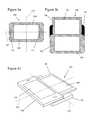
- FIG. 4illustrates a further embodiment of a motion coupler/mechanism fitted to a device 300 according to an embodiment of the invention.
- FIG. 4 ashows the device 300 with the base member 310 , first part 302 and second part 306 all visible.
- FIGS. 4 b , 4 c and 4 ddo not include the base member 310 and its associated pin ( 330 ).
- the mechanismincludes a first pin 330 that is connected to the base member 310 .
- the first pin 330is configured to maintain a desired position of the base member 310 relative to the first part 302 and the second part 306 of the device 300 in operation.
- the base member 310is kept in the middle (in a lateral direction) of the first and second parts 302 , 306 .
- the base member 310can provide support for the two parts 302 , 306 , especially when the device 300 is in the open configuration, and providing the base member centrally with regard to the first and second parts 302 , 306 can enable the maximum offset/overhang of the two parts 302 , 306 in relation to the base member 310 to be reduced, and in some embodiments to be kept to a minimum whilst still providing full exposure of the user interfaces associated with the first and second parts 302 , 306 .
- the apparatuscan enable all of the user interface associated with the second part 306 to be exposed in the open configuration without requiring undue overhang of the first and second parts 302 , 306 over the sides of the base member 310 . Reducing the overhang can improve the mechanical strength of the device 300 .
- the mechanismalso includes a second pin 332 that is connected to the second part 306 of the device 300 .
- Pivotally connected to the first part 306 of the device 300is a lever 334 .
- the lever 334is pivotally connected at pivot point 340 to a corner of the first part 302 .
- the lever 334is pivotally connected to the first part such that it is positioned between the second part 306 and the housing 310 so that it can interact with the first and second pins 330 , 332 as described below.
- the second part 306is smaller than the first part 302 such that the lever 334 can be pivotally connected to a region of the first part 302 that overlaps the second part 36 .
- the second part 306is longitudinally shorter than the first part 302 and the lever 334 is pivotally connected to a corner of the first part 302 that is at a longitudinal end of the first part 302 that overlaps a longitudinal end of the second part 306 .
- the levercan be located on top of (in FIG. 4 ) the second part 306 such that it is located between the second part 306 and the base member 310 .
- the second part 306includes a cut-out region 342 that confines the scope of movement of the lever 334 .
- the cut-out region 342is etched into the second part 306 to provide a recess in which the lever 334 can move, as discussed below.
- the lever 334has a first longitudinal slot 336 that accommodates the first base member pin 330 in use, and a second longitudinal slot 338 that accommodates the second part pin 332 . It will be appreciated that the slots, 336 , 338 in the lever 334 can accommodate movement of the pins 330 , 332 along the length of the slots as the configuration of the device 300 is changed and the lever 334 pivots about its pivot point 340 .
- FIG. 4 bshows the device 300 with the mechanism in a first, closed configuration.
- FIG. 4 cshows the same device 300 in a half-open/half-closed configuration.
- an external user applied forcehas been applied to the first part 302 in a lateral direction.
- the pivotally connected lever 334is caused to rotate about its pivot point 340 in order to retain the first base member pin 330 in the first longitudinal slot 336 .
- the lever 334rotates in this way, it applies a force to the second part pin 332 that causes the second part 306 to move in the opposite direction to the first part 302 .
- the user applied, external force applied to the first part 302causes the mechanism to apply an internal force to the second part 306 that causes the first and second part 302 , 306 to move in opposing directions with respect to the base member.
- An internal forcemay be considered as one that is provided by the mechanism/apparatus in response to a user applied external force.
- lever pivoting about pivot point 340 relative to the first partit may also be considered to pivot about the base member pin 330 such that the region of the lever to one side of the pin 330 applies a force to one part 302 , 306 and the region of the lever to the other side of the base member pin 330 applies a force to the other part 302 , 306 .
- FIG. 4 dillustrates the device 300 in a fully open, second configuration whereby the first part 302 has reached a maximum extent of its travel as defined by one or more of the cut-out 342 in the second part 306 and/or the length of the slots 336 , 338 in the lever 334 .
- the ratio of the movement of the two partscan be modified by changing the lever and pin geometry.
- the apparatuscould be configured to provide a tilting mechanism in order to tilt the display/user output interface.
- a mechanismwhen the display module of the device is slid open, a mechanism (there are several possibilities of mechanism including gears, levers, over-centre springs and magnets) forces the keymat module toward the user. The reverse happens when the screen is slid closed.
- the distance moved by the slidecan be the same as the size of the keymat that is revealed.
- apparatus/device/server and/or other features of particular apparatus/device/servermay be provided by apparatus arranged such that they become configured to carry out the desired operations only when enabled, e.g. switched on, or the like. In such cases, they may not necessarily have the appropriate software loaded into the active memory in the non-enabled (e.g. switched off state) and only load the appropriate software in the enabled (e.g. on state).
- the apparatusmay comprise hardware circuitry and/or firmware.
- the apparatusmay comprise software loaded onto memory. Such software/computer programs may be recorded on the same memory/processor and/or on one or more memories/processors.
- One or more disclosed aspectsmay encompass the electronic distribution of associated computer programs and computer programs (which may be source/transport encoded) recorded on an appropriate carrier (e.g. memory, signal).
- an appropriate carriere.g. memory, signal
- processors and memorymay comprise a computer processor, Application Specific Integrated Circuit (ASIC), field-programmable gate array (FPGA), and/or other hardware components that have been programmed in such a way to carry out the inventive function.
- ASICApplication Specific Integrated Circuit
- FPGAfield-programmable gate array
Landscapes
- Engineering & Computer Science (AREA)
- Theoretical Computer Science (AREA)
- Physics & Mathematics (AREA)
- Computer Hardware Design (AREA)
- Human Computer Interaction (AREA)
- General Engineering & Computer Science (AREA)
- General Physics & Mathematics (AREA)
- Signal Processing (AREA)
- Mathematical Physics (AREA)
- Telephone Set Structure (AREA)
Abstract
Description
- a first pin connected to the base;
- a second pin connected to the user input interface; and
- a lever pivotally connected to the user output interface, wherein the lever comprises one or more slots configured to accommodate the first and second pins, such that movement of the lever about its pivot point as the apparatus changes configuration causes movement of the user input interface and user output interface in opposite directions.
- a housing;
- a first part comprising a first user interface;
- a second part comprising a second user interface; and
- a motion coupler coupled between the first part and the second part;
- wherein the apparatus is configured such that the first part and second part are laterally slidable relative to each other, and also laterally slidable relative to the housing, to define first and second configurations;
- the second user interface being exposed and the first user interface being concealed by the second part, when the apparatus is in the first configuration;
- the first and second user interfaces being exposed when the apparatus is in the second configuration;
- wherein the motion coupler is configured to apply a force to the second part when an external force is applied to the first part to change the configuration of the apparatus, wherein the force applied to the second part is in the opposite direction to the force applied to the first part.
Claims (25)
Priority Applications (7)
| Application Number | Priority Date | Filing Date | Title |
|---|---|---|---|
| US12/339,386US8385992B2 (en) | 2008-12-19 | 2008-12-19 | User interfaces and associated apparatus and methods |
| KR1020117007082AKR101251233B1 (en) | 2008-08-29 | 2009-08-05 | User interfaces and associated apparatus and methods |
| RU2011111183/08ARU2476921C2 (en) | 2008-08-29 | 2009-08-05 | User interface and corresponding method and device |
| EP20090809375EP2340474B1 (en) | 2008-08-29 | 2009-08-05 | Apparatus for a portable electronic device |
| PCT/FI2009/050648WO2010023354A1 (en) | 2008-08-29 | 2009-08-05 | User interfaces and associated apparatus and methods |
| CN200980133374.8ACN102138115B (en) | 2008-08-29 | 2009-08-05 | User interface and related devices and methods |
| TW098129046ATW201015423A (en) | 2008-08-29 | 2009-08-28 | User interfaces and associated apparatus and methods |
Applications Claiming Priority (1)
| Application Number | Priority Date | Filing Date | Title |
|---|---|---|---|
| US12/339,386US8385992B2 (en) | 2008-12-19 | 2008-12-19 | User interfaces and associated apparatus and methods |
Publications (2)
| Publication Number | Publication Date |
|---|---|
| US20100159993A1 US20100159993A1 (en) | 2010-06-24 |
| US8385992B2true US8385992B2 (en) | 2013-02-26 |
Family
ID=42266904
Family Applications (1)
| Application Number | Title | Priority Date | Filing Date |
|---|---|---|---|
| US12/339,386Expired - Fee RelatedUS8385992B2 (en) | 2008-08-29 | 2008-12-19 | User interfaces and associated apparatus and methods |
Country Status (1)
| Country | Link |
|---|---|
| US (1) | US8385992B2 (en) |
Cited By (7)
| Publication number | Priority date | Publication date | Assignee | Title |
|---|---|---|---|---|
| US20120019993A1 (en)* | 2010-07-20 | 2012-01-26 | Htc Corporation | Handheld electronic device |
| US20130021734A1 (en)* | 2011-07-24 | 2013-01-24 | Tara Chand Singhal | Apparatus and method for additional screen in a portable computing and communication device |
| US20130044409A1 (en)* | 2011-08-16 | 2013-02-21 | Albert Murray Pegg | Apparatus and methods for moving an input interface relative to a display of an electronic device |
| USD701862S1 (en)* | 2011-02-18 | 2014-04-01 | Lg Electronics Inc. | Cart barcode scanner |
| US20150309557A1 (en)* | 2012-07-02 | 2015-10-29 | Guowen Hu | Insertable housing for electronic device |
| US10048920B1 (en)* | 2017-06-13 | 2018-08-14 | International Business Machines Corporation | Extendable display strips |
| US20180343760A1 (en)* | 2017-05-23 | 2018-11-29 | Compal Electronics, Inc. | Electronic device |
Families Citing this family (12)
| Publication number | Priority date | Publication date | Assignee | Title |
|---|---|---|---|---|
| KR101562582B1 (en)* | 2008-12-30 | 2015-10-22 | 엘지전자 주식회사 | Mobile terminal to which a flexible display is applied and its screen enlargement method |
| CN101860579A (en)* | 2009-04-10 | 2010-10-13 | 鸿富锦精密工业(深圳)有限公司 | portable electronic device |
| KR20100129416A (en)* | 2009-06-01 | 2010-12-09 | 삼성전자주식회사 | Input mode operation method of a mobile terminal having a plurality of input means |
| KR101591524B1 (en)* | 2009-08-25 | 2016-02-03 | 엘지전자 주식회사 | Method for displaying menu of mobile communication terminal and mobile communication terminal |
| US9154592B2 (en)* | 2010-02-05 | 2015-10-06 | Microsoft Technology Licensing, Llc | Moveable housing of a mobile communications device |
| US8600460B2 (en)* | 2010-04-12 | 2013-12-03 | Blackberry Limited | Handheld electronic communication device including touch-sensitive display and method |
| CN102340951B (en)* | 2010-07-23 | 2014-05-21 | 宏达国际电子股份有限公司 | handheld electronic device |
| TWI426766B (en)* | 2010-07-30 | 2014-02-11 | Htc Corp | Handheld electronic device |
| US8406420B2 (en)* | 2011-06-24 | 2013-03-26 | First Dome Corporation | Magnetic-push slide cover driving device |
| CN103152447B (en)* | 2011-12-07 | 2016-03-30 | 宏达国际电子股份有限公司 | handheld electronic device |
| US20190101957A1 (en)* | 2017-10-04 | 2019-04-04 | Scott Alexander | Cell Tablet |
| CN115013644B (en)* | 2022-06-30 | 2024-02-27 | 联想(北京)有限公司 | Supporting device and electronic equipment |
Citations (53)
| Publication number | Priority date | Publication date | Assignee | Title |
|---|---|---|---|---|
| GB2350516A (en) | 1999-05-26 | 2000-11-29 | Ericsson Telefon Ab L M | Telephone handset with at least two movable elements whose motion is linked or is initiated by pushbutton or incoming call |
| WO2000079372A1 (en) | 1999-06-22 | 2000-12-28 | Colvin David S | Personal digital assistant with multiple displays |
| US6295038B1 (en) | 1998-04-16 | 2001-09-25 | Carlton S. Rebeske | Laptop computer |
| EP1148692A2 (en) | 2000-04-18 | 2001-10-24 | Nokia Mobile Phones Ltd. | Portable electronic device |
| US20010034250A1 (en) | 2000-01-24 | 2001-10-25 | Sanjay Chadha | Hand-held personal computing device with microdisplay |
| US6381128B1 (en) | 2000-07-17 | 2002-04-30 | Russel G. Kramer | Ergonomic portable computer |
| EP1313297A1 (en) | 1995-11-24 | 2003-05-21 | Nokia Corporation | Double-acting communication device |
| WO2003081880A1 (en) | 2002-03-21 | 2003-10-02 | Nokia Corporation | Mobile electronic device having a pivoted display |
| US20030206394A1 (en) | 2000-12-16 | 2003-11-06 | Kamran Ossia | Multi-mode handheld computer and remote control |
| DE20318035U1 (en) | 2003-11-03 | 2004-02-26 | Krukkert, Peter | Double sided display for computer and television has separately activated front and rear screen |
| US6748249B1 (en) | 1999-05-03 | 2004-06-08 | Nokia Mobile Phones, Ltd. | Electronic device with a sliding lid |
| US20050052835A1 (en) | 2003-09-10 | 2005-03-10 | Chi-Jung Wu | Dual-screen display apparatus and information processing apparatus having the same |
| WO2005034485A2 (en) | 2003-09-12 | 2005-04-14 | Motorola Inc. | Communication device having multiple keypads |
| US20050085273A1 (en) | 2003-10-20 | 2005-04-21 | Khalid Mohammad T. | Portable device having rotatable display |
| GB2407933A (en) | 2003-11-06 | 2005-05-11 | Inventec Appliances Corp | Mobile telephone having two slidable keypads moving in different directions |
| US20050143137A1 (en) | 2003-12-25 | 2005-06-30 | Fujitsu Limited | Terminal apparatus |
| EP1594289A2 (en) | 2004-05-03 | 2005-11-09 | Samsung Electronics Co., Ltd. | Double sliding-type portable communication apparatus |
| WO2006034309A1 (en) | 2004-09-20 | 2006-03-30 | Qualcomm Incorporated | Electronic device with three movable layers |
| US20060183505A1 (en) | 2005-02-15 | 2006-08-17 | Willrich Scott Consulting Group, Inc. | Digital mobile planner |
| US20060197753A1 (en) | 2005-03-04 | 2006-09-07 | Hotelling Steven P | Multi-functional hand-held device |
| US20060211454A1 (en) | 2004-09-14 | 2006-09-21 | Lg Electronics Inc. | Display apparatus and method for mobile terminal |
| EP1722538A1 (en) | 2005-05-13 | 2006-11-15 | High Tech Computer Corp. | Sliding-type handheld electronic device with dual operation mode and two keyboards |
| US20070037618A1 (en) | 2005-08-10 | 2007-02-15 | Lee Kyung J | Mobile terminal having an additional keypad |
| US20070046561A1 (en) | 2005-08-23 | 2007-03-01 | Lg Electronics Inc. | Mobile communication terminal for displaying information |
| US20070065220A1 (en) | 2005-09-19 | 2007-03-22 | Nokia Corporation | Portable electronic device |
| US20070075915A1 (en) | 2005-09-26 | 2007-04-05 | Lg Electronics Inc. | Mobile communication terminal having multiple displays and a data processing method thereof |
| US20070076861A1 (en) | 2005-09-30 | 2007-04-05 | Lg Electronics Inc. | Mobile terminal having a plurality of displays |
| WO2007140911A1 (en) | 2006-06-09 | 2007-12-13 | Nokia Corporation | A layered mobile device |
| US7330548B2 (en) | 2003-11-01 | 2008-02-12 | Samsung Electronics Co., Ltd | Mobile terminal and sliding module and a method thereof |
| US20080051041A1 (en)* | 2006-08-28 | 2008-02-28 | Research In Motion Limited | Hybrid portrait-landscape handheld device with trackball navigation and qwerty hide-away keyboard |
| US20080161075A1 (en)* | 2006-04-04 | 2008-07-03 | M2Sys Co., Ltd. | Slide-Up Opening and Closing Mechanism For Portable Terminal |
| EP1950937A2 (en) | 2007-01-29 | 2008-07-30 | Samsung Electronics Co.,Ltd. | Portable apparatus |
| WO2008101519A1 (en) | 2007-02-23 | 2008-08-28 | Nokia Corporation | Electronic device with movable housing parts |
| US20080207273A1 (en) | 2007-02-25 | 2008-08-28 | Samsung Electronics Co., Ltd. | Sliding-type mobile phone with a supplemental display secreen |
| US20080225014A1 (en) | 2007-03-15 | 2008-09-18 | Taehun Kim | Electronic device and method of controlling mode thereof and mobile communication terminal |
| US20080244452A1 (en) | 2006-12-04 | 2008-10-02 | Samsung Electronics Co., Ltd. | Method and terminal for implementing preview function |
| US20090009423A1 (en) | 2007-07-07 | 2009-01-08 | Yuming Huang | Variable size electronic display based on slide-out and slide-in mechanism |
| EP2034700A1 (en) | 2007-09-10 | 2009-03-11 | Samkwang Industry Co., Ltd. | Sliding-type mobile communication terminal |
| US20090093285A1 (en)* | 2007-10-05 | 2009-04-09 | Benq Corporation | Bilateral sliding module and the electronic device using the same |
| US7574241B2 (en)* | 2004-05-06 | 2009-08-11 | Samsung Electronics Co., Ltd | Sliding/folding-type portable apparatus |
| US7577466B2 (en)* | 2005-12-21 | 2009-08-18 | Pantech Co., Ltd. | Portable device including display unit and keypad unit |
| US7930009B2 (en)* | 2007-06-20 | 2011-04-19 | Sony Corporation | Slide mechanism and electronic apparatus |
| US7986983B2 (en)* | 2007-12-28 | 2011-07-26 | Motorola Mobility, Inc. | Methods and slider form factor devices with continguous surfaces when open |
| US8014845B2 (en)* | 2008-05-19 | 2011-09-06 | Fujitsu Limited | Information terminal device |
| US8032192B2 (en)* | 2006-06-08 | 2011-10-04 | Samsung Electronics Co., Ltd. | Portable terminal and sliding/swing-type cradling apparatus thereof |
| US8046037B2 (en)* | 2008-03-25 | 2011-10-25 | Lg Electronics Inc. | Slide module and mobile terminal having the same |
| US8081449B2 (en)* | 2008-12-12 | 2011-12-20 | Htc Corporation | Handheld electronic device and operating method thereof |
| US8086290B2 (en)* | 2005-11-07 | 2011-12-27 | Samsung Electronics Co., Ltd. | Mobile phone with a sliding cradle for providing visual and acoustic convenience |
| US8107235B2 (en)* | 2007-11-07 | 2012-01-31 | Htc Corporation | Electronic device |
| US8160660B2 (en)* | 2006-07-28 | 2012-04-17 | Sharp Kabushiki Kaisha | Dual slide portable terminal |
| US8164890B2 (en)* | 2009-10-22 | 2012-04-24 | Shenzhen Futaihong Precision Industry Co., Ltd. | Sliding and tilting mechanism and portable electronic device using the same |
| US8170632B2 (en)* | 2009-02-03 | 2012-05-01 | Inventec Appliances Corp. | Electronic device and operation method thereof |
| US8190219B2 (en)* | 2006-04-28 | 2012-05-29 | Samsung Electronics Co., Ltd. | Sliding-tilt unit and mobile device using the same |
- 2008
- 2008-12-19USUS12/339,386patent/US8385992B2/ennot_activeExpired - Fee Related
Patent Citations (53)
| Publication number | Priority date | Publication date | Assignee | Title |
|---|---|---|---|---|
| EP1313297A1 (en) | 1995-11-24 | 2003-05-21 | Nokia Corporation | Double-acting communication device |
| US6295038B1 (en) | 1998-04-16 | 2001-09-25 | Carlton S. Rebeske | Laptop computer |
| US6748249B1 (en) | 1999-05-03 | 2004-06-08 | Nokia Mobile Phones, Ltd. | Electronic device with a sliding lid |
| GB2350516A (en) | 1999-05-26 | 2000-11-29 | Ericsson Telefon Ab L M | Telephone handset with at least two movable elements whose motion is linked or is initiated by pushbutton or incoming call |
| WO2000079372A1 (en) | 1999-06-22 | 2000-12-28 | Colvin David S | Personal digital assistant with multiple displays |
| US20010034250A1 (en) | 2000-01-24 | 2001-10-25 | Sanjay Chadha | Hand-held personal computing device with microdisplay |
| EP1148692A2 (en) | 2000-04-18 | 2001-10-24 | Nokia Mobile Phones Ltd. | Portable electronic device |
| US6381128B1 (en) | 2000-07-17 | 2002-04-30 | Russel G. Kramer | Ergonomic portable computer |
| US20030206394A1 (en) | 2000-12-16 | 2003-11-06 | Kamran Ossia | Multi-mode handheld computer and remote control |
| WO2003081880A1 (en) | 2002-03-21 | 2003-10-02 | Nokia Corporation | Mobile electronic device having a pivoted display |
| US20050052835A1 (en) | 2003-09-10 | 2005-03-10 | Chi-Jung Wu | Dual-screen display apparatus and information processing apparatus having the same |
| WO2005034485A2 (en) | 2003-09-12 | 2005-04-14 | Motorola Inc. | Communication device having multiple keypads |
| US20050085273A1 (en) | 2003-10-20 | 2005-04-21 | Khalid Mohammad T. | Portable device having rotatable display |
| US7330548B2 (en) | 2003-11-01 | 2008-02-12 | Samsung Electronics Co., Ltd | Mobile terminal and sliding module and a method thereof |
| DE20318035U1 (en) | 2003-11-03 | 2004-02-26 | Krukkert, Peter | Double sided display for computer and television has separately activated front and rear screen |
| GB2407933A (en) | 2003-11-06 | 2005-05-11 | Inventec Appliances Corp | Mobile telephone having two slidable keypads moving in different directions |
| US20050143137A1 (en) | 2003-12-25 | 2005-06-30 | Fujitsu Limited | Terminal apparatus |
| EP1594289A2 (en) | 2004-05-03 | 2005-11-09 | Samsung Electronics Co., Ltd. | Double sliding-type portable communication apparatus |
| US7574241B2 (en)* | 2004-05-06 | 2009-08-11 | Samsung Electronics Co., Ltd | Sliding/folding-type portable apparatus |
| US20060211454A1 (en) | 2004-09-14 | 2006-09-21 | Lg Electronics Inc. | Display apparatus and method for mobile terminal |
| WO2006034309A1 (en) | 2004-09-20 | 2006-03-30 | Qualcomm Incorporated | Electronic device with three movable layers |
| US20060183505A1 (en) | 2005-02-15 | 2006-08-17 | Willrich Scott Consulting Group, Inc. | Digital mobile planner |
| US20060197753A1 (en) | 2005-03-04 | 2006-09-07 | Hotelling Steven P | Multi-functional hand-held device |
| EP1722538A1 (en) | 2005-05-13 | 2006-11-15 | High Tech Computer Corp. | Sliding-type handheld electronic device with dual operation mode and two keyboards |
| US20070037618A1 (en) | 2005-08-10 | 2007-02-15 | Lee Kyung J | Mobile terminal having an additional keypad |
| US20070046561A1 (en) | 2005-08-23 | 2007-03-01 | Lg Electronics Inc. | Mobile communication terminal for displaying information |
| US20070065220A1 (en) | 2005-09-19 | 2007-03-22 | Nokia Corporation | Portable electronic device |
| US20070075915A1 (en) | 2005-09-26 | 2007-04-05 | Lg Electronics Inc. | Mobile communication terminal having multiple displays and a data processing method thereof |
| US20070076861A1 (en) | 2005-09-30 | 2007-04-05 | Lg Electronics Inc. | Mobile terminal having a plurality of displays |
| US8086290B2 (en)* | 2005-11-07 | 2011-12-27 | Samsung Electronics Co., Ltd. | Mobile phone with a sliding cradle for providing visual and acoustic convenience |
| US7577466B2 (en)* | 2005-12-21 | 2009-08-18 | Pantech Co., Ltd. | Portable device including display unit and keypad unit |
| US20080161075A1 (en)* | 2006-04-04 | 2008-07-03 | M2Sys Co., Ltd. | Slide-Up Opening and Closing Mechanism For Portable Terminal |
| US8190219B2 (en)* | 2006-04-28 | 2012-05-29 | Samsung Electronics Co., Ltd. | Sliding-tilt unit and mobile device using the same |
| US8032192B2 (en)* | 2006-06-08 | 2011-10-04 | Samsung Electronics Co., Ltd. | Portable terminal and sliding/swing-type cradling apparatus thereof |
| WO2007140911A1 (en) | 2006-06-09 | 2007-12-13 | Nokia Corporation | A layered mobile device |
| US8160660B2 (en)* | 2006-07-28 | 2012-04-17 | Sharp Kabushiki Kaisha | Dual slide portable terminal |
| US20080051041A1 (en)* | 2006-08-28 | 2008-02-28 | Research In Motion Limited | Hybrid portrait-landscape handheld device with trackball navigation and qwerty hide-away keyboard |
| US20080244452A1 (en) | 2006-12-04 | 2008-10-02 | Samsung Electronics Co., Ltd. | Method and terminal for implementing preview function |
| EP1950937A2 (en) | 2007-01-29 | 2008-07-30 | Samsung Electronics Co.,Ltd. | Portable apparatus |
| WO2008101519A1 (en) | 2007-02-23 | 2008-08-28 | Nokia Corporation | Electronic device with movable housing parts |
| US20080207273A1 (en) | 2007-02-25 | 2008-08-28 | Samsung Electronics Co., Ltd. | Sliding-type mobile phone with a supplemental display secreen |
| US20080225014A1 (en) | 2007-03-15 | 2008-09-18 | Taehun Kim | Electronic device and method of controlling mode thereof and mobile communication terminal |
| US7930009B2 (en)* | 2007-06-20 | 2011-04-19 | Sony Corporation | Slide mechanism and electronic apparatus |
| US20090009423A1 (en) | 2007-07-07 | 2009-01-08 | Yuming Huang | Variable size electronic display based on slide-out and slide-in mechanism |
| EP2034700A1 (en) | 2007-09-10 | 2009-03-11 | Samkwang Industry Co., Ltd. | Sliding-type mobile communication terminal |
| US20090093285A1 (en)* | 2007-10-05 | 2009-04-09 | Benq Corporation | Bilateral sliding module and the electronic device using the same |
| US8107235B2 (en)* | 2007-11-07 | 2012-01-31 | Htc Corporation | Electronic device |
| US7986983B2 (en)* | 2007-12-28 | 2011-07-26 | Motorola Mobility, Inc. | Methods and slider form factor devices with continguous surfaces when open |
| US8046037B2 (en)* | 2008-03-25 | 2011-10-25 | Lg Electronics Inc. | Slide module and mobile terminal having the same |
| US8014845B2 (en)* | 2008-05-19 | 2011-09-06 | Fujitsu Limited | Information terminal device |
| US8081449B2 (en)* | 2008-12-12 | 2011-12-20 | Htc Corporation | Handheld electronic device and operating method thereof |
| US8170632B2 (en)* | 2009-02-03 | 2012-05-01 | Inventec Appliances Corp. | Electronic device and operation method thereof |
| US8164890B2 (en)* | 2009-10-22 | 2012-04-24 | Shenzhen Futaihong Precision Industry Co., Ltd. | Sliding and tilting mechanism and portable electronic device using the same |
Non-Patent Citations (15)
| Title |
|---|
| International Search Report and Written Opinion for Application No. PCT/FI2009/050646 dated Nov. 6, 2009. |
| International Search Report for Application No. PCT/EP2008/061439 dated May 4, 2009. |
| LG KF600 Slider Dual Display Handset [online] [retrieved Nov. 21, 2008]. Retrieved from the Internet: . 2 pages (dated May 30, 2008). |
| LG KF600 Slider Dual Display Handset [online] [retrieved Nov. 21, 2008]. Retrieved from the Internet: <URL: http://allaboutmobilz.blogspot.com/2008/05/lg-kf600-slider-dual-display-handset.html>. 2 pages (dated May 30, 2008). |
| Office Action for European Application No. 08 803 425.1 dated Feb. 29, 2012. |
| Office Action for European Application No. 09 809 374.3 dated Mar. 20, 2012. |
| Office Action for European Application No. 09 809 375.0 dated Mar. 20, 2012. |
| Office Action for Russian Application No. 2011111183/08(016515) dated Jun. 1, 2012. |
| Office Action for U.S. Appl. No. 12/339,351 dated Jan. 31, 2012. |
| Office Action for U.S. Appl. No. 12/339,351 dated Jul. 20, 2011. |
| Office Action from Chinese Patent Application No. 200980133374.8 dated Oct. 10, 2012. |
| Office Action from Korean Patent Application No. 2011-7007082 dated Aug. 27, 2012. |
| Plica phone concept with dual screen display [online] [retrieved Nov. 21, 2008]. Retrieved from the Internet: . 2 pages (dated Jul. 30, 2008). |
| Plica phone concept with dual screen display [online] [retrieved Nov. 21, 2008]. Retrieved from the Internet: <URL: http://www.slippertybrick.com/2008/07/plica-hone-concept-with-dual-screen-display>. 2 pages (dated Jul. 30, 2008). |
| Supplementary European Search Report for Application No. 09 809 375.0 dated Mar. 2, 2012. |
Cited By (11)
| Publication number | Priority date | Publication date | Assignee | Title |
|---|---|---|---|---|
| US20120019993A1 (en)* | 2010-07-20 | 2012-01-26 | Htc Corporation | Handheld electronic device |
| US8599553B2 (en)* | 2010-07-20 | 2013-12-03 | Htc Corporation | Handheld electronic device |
| USD701862S1 (en)* | 2011-02-18 | 2014-04-01 | Lg Electronics Inc. | Cart barcode scanner |
| US20130021734A1 (en)* | 2011-07-24 | 2013-01-24 | Tara Chand Singhal | Apparatus and method for additional screen in a portable computing and communication device |
| US8681486B2 (en)* | 2011-07-24 | 2014-03-25 | Tara Chand Singhal | Apparatus and method for additional screen in a portable computing and communication device |
| US20130044409A1 (en)* | 2011-08-16 | 2013-02-21 | Albert Murray Pegg | Apparatus and methods for moving an input interface relative to a display of an electronic device |
| US20150309557A1 (en)* | 2012-07-02 | 2015-10-29 | Guowen Hu | Insertable housing for electronic device |
| US20180343760A1 (en)* | 2017-05-23 | 2018-11-29 | Compal Electronics, Inc. | Electronic device |
| US10973144B2 (en)* | 2017-05-23 | 2021-04-06 | Compal Electronics, Inc. | Electronic device |
| US10048920B1 (en)* | 2017-06-13 | 2018-08-14 | International Business Machines Corporation | Extendable display strips |
| US10203929B2 (en) | 2017-06-13 | 2019-02-12 | International Business Machines Corporation | Extendable display strips |
Also Published As
| Publication number | Publication date |
|---|---|
| US20100159993A1 (en) | 2010-06-24 |
Similar Documents
| Publication | Publication Date | Title |
|---|---|---|
| US8385992B2 (en) | User interfaces and associated apparatus and methods | |
| US7622685B2 (en) | Portable information terminal | |
| US8208249B2 (en) | Portable information terminal | |
| US8587938B2 (en) | Portable communication device and cradle apparatus thereof | |
| US20100075726A1 (en) | Portable terminal for multimedia | |
| KR100762671B1 (en) | Portable communication terminal having a display unit using a light receiving panel | |
| EP1806909B1 (en) | Portable communication terminal for games and user interfacing device thereof | |
| EP2242237A1 (en) | Portable electronic device | |
| US8108016B2 (en) | Portable communication device having a dual sliding flip hinge assembly | |
| EP2449455A1 (en) | Display apparatus and associated methods | |
| EP2340474B1 (en) | Apparatus for a portable electronic device | |
| WO2011095675A1 (en) | Apparatus for a portable electronic device | |
| JP2011049805A (en) | Mobile terminal | |
| US8249677B2 (en) | Handheld electronic device | |
| EP2202948B1 (en) | Portable information processing terminal | |
| JP2011515929A (en) | Mobile communication device having slider and flip hinge assembly | |
| US7221559B1 (en) | Multipurpose bumper system for a data processing apparatus | |
| KR20070109779A (en) | Mobile device structure | |
| KR20070109798A (en) | Mobile device structure | |
| KR100800753B1 (en) | Double-sided sliding type mobile terminal | |
| KR20130045107A (en) | Mobile device | |
| JP5121742B2 (en) | Display device | |
| CN101902889A (en) | handheld electronic device | |
| CN101340466A (en) | Portable electronic device | |
| CN1668046A (en) | Portable communication device with game function |
Legal Events
| Date | Code | Title | Description |
|---|---|---|---|
| AS | Assignment | Owner name:NOKIA CORPORATION,FINLAND Free format text:ASSIGNMENT OF ASSIGNORS INTEREST;ASSIGNORS:DAVIDSON, BRIAN;BARNETT, RICKY;REEL/FRAME:022356/0080 Effective date:20090121 Owner name:NOKIA CORPORATION, FINLAND Free format text:ASSIGNMENT OF ASSIGNORS INTEREST;ASSIGNORS:DAVIDSON, BRIAN;BARNETT, RICKY;REEL/FRAME:022356/0080 Effective date:20090121 | |
| FEPP | Fee payment procedure | Free format text:PAYOR NUMBER ASSIGNED (ORIGINAL EVENT CODE: ASPN); ENTITY STATUS OF PATENT OWNER: LARGE ENTITY Free format text:PAYER NUMBER DE-ASSIGNED (ORIGINAL EVENT CODE: RMPN); ENTITY STATUS OF PATENT OWNER: LARGE ENTITY | |
| STCF | Information on status: patent grant | Free format text:PATENTED CASE | |
| AS | Assignment | Owner name:NOKIA TECHNOLOGIES OY, FINLAND Free format text:ASSIGNMENT OF ASSIGNORS INTEREST;ASSIGNOR:NOKIA CORPORATION;REEL/FRAME:035445/0496 Effective date:20150116 | |
| FPAY | Fee payment | Year of fee payment:4 | |
| FEPP | Fee payment procedure | Free format text:MAINTENANCE FEE REMINDER MAILED (ORIGINAL EVENT CODE: REM.); ENTITY STATUS OF PATENT OWNER: LARGE ENTITY | |
| LAPS | Lapse for failure to pay maintenance fees | Free format text:PATENT EXPIRED FOR FAILURE TO PAY MAINTENANCE FEES (ORIGINAL EVENT CODE: EXP.); ENTITY STATUS OF PATENT OWNER: LARGE ENTITY | |
| STCH | Information on status: patent discontinuation | Free format text:PATENT EXPIRED DUE TO NONPAYMENT OF MAINTENANCE FEES UNDER 37 CFR 1.362 | |
| FP | Lapsed due to failure to pay maintenance fee | Effective date:20210226 |