US8385822B2 - Orientation and presence detection for use in configuring operations of computing devices in docked environments - Google Patents
Orientation and presence detection for use in configuring operations of computing devices in docked environmentsDownload PDFInfo
- Publication number
- US8385822B2 US8385822B2US12/239,656US23965608AUS8385822B2US 8385822 B2US8385822 B2US 8385822B2US 23965608 AUS23965608 AUS 23965608AUS 8385822 B2US8385822 B2US 8385822B2
- Authority
- US
- United States
- Prior art keywords
- mcd
- dock
- signal
- data
- mobile computing
- Prior art date
- Legal status (The legal status is an assumption and is not a legal conclusion. Google has not performed a legal analysis and makes no representation as to the accuracy of the status listed.)
- Expired - Fee Related, expires
Links
Images


Classifications
- H—ELECTRICITY
- H04—ELECTRIC COMMUNICATION TECHNIQUE
- H04M—TELEPHONIC COMMUNICATION
- H04M1/00—Substation equipment, e.g. for use by subscribers
- H04M1/02—Constructional features of telephone sets
- H04M1/04—Supports for telephone transmitters or receivers
- G—PHYSICS
- G06—COMPUTING OR CALCULATING; COUNTING
- G06F—ELECTRIC DIGITAL DATA PROCESSING
- G06F1/00—Details not covered by groups G06F3/00 - G06F13/00 and G06F21/00
- G06F1/16—Constructional details or arrangements
- G06F1/1613—Constructional details or arrangements for portable computers
- G06F1/1632—External expansion units, e.g. docking stations
- H—ELECTRICITY
- H02—GENERATION; CONVERSION OR DISTRIBUTION OF ELECTRIC POWER
- H02J—CIRCUIT ARRANGEMENTS OR SYSTEMS FOR SUPPLYING OR DISTRIBUTING ELECTRIC POWER; SYSTEMS FOR STORING ELECTRIC ENERGY
- H02J50/00—Circuit arrangements or systems for wireless supply or distribution of electric power
- H02J50/005—Mechanical details of housing or structure aiming to accommodate the power transfer means, e.g. mechanical integration of coils, antennas or transducers into emitting or receiving devices
- H—ELECTRICITY
- H02—GENERATION; CONVERSION OR DISTRIBUTION OF ELECTRIC POWER
- H02J—CIRCUIT ARRANGEMENTS OR SYSTEMS FOR SUPPLYING OR DISTRIBUTING ELECTRIC POWER; SYSTEMS FOR STORING ELECTRIC ENERGY
- H02J50/00—Circuit arrangements or systems for wireless supply or distribution of electric power
- H02J50/10—Circuit arrangements or systems for wireless supply or distribution of electric power using inductive coupling
- H—ELECTRICITY
- H02—GENERATION; CONVERSION OR DISTRIBUTION OF ELECTRIC POWER
- H02J—CIRCUIT ARRANGEMENTS OR SYSTEMS FOR SUPPLYING OR DISTRIBUTING ELECTRIC POWER; SYSTEMS FOR STORING ELECTRIC ENERGY
- H02J50/00—Circuit arrangements or systems for wireless supply or distribution of electric power
- H02J50/80—Circuit arrangements or systems for wireless supply or distribution of electric power involving the exchange of data, concerning supply or distribution of electric power, between transmitting devices and receiving devices
- H—ELECTRICITY
- H04—ELECTRIC COMMUNICATION TECHNIQUE
- H04M—TELEPHONIC COMMUNICATION
- H04M1/00—Substation equipment, e.g. for use by subscribers
- H04M1/72—Mobile telephones; Cordless telephones, i.e. devices for establishing wireless links to base stations without route selection
- H04M1/724—User interfaces specially adapted for cordless or mobile telephones
- H04M1/72403—User interfaces specially adapted for cordless or mobile telephones with means for local support of applications that increase the functionality
- H04M1/72409—User interfaces specially adapted for cordless or mobile telephones with means for local support of applications that increase the functionality by interfacing with external accessories
- H—ELECTRICITY
- H02—GENERATION; CONVERSION OR DISTRIBUTION OF ELECTRIC POWER
- H02J—CIRCUIT ARRANGEMENTS OR SYSTEMS FOR SUPPLYING OR DISTRIBUTING ELECTRIC POWER; SYSTEMS FOR STORING ELECTRIC ENERGY
- H02J7/00—Circuit arrangements for charging or depolarising batteries or for supplying loads from batteries
- H02J7/0042—Circuit arrangements for charging or depolarising batteries or for supplying loads from batteries characterised by the mechanical construction
- H02J7/0044—Circuit arrangements for charging or depolarising batteries or for supplying loads from batteries characterised by the mechanical construction specially adapted for holding portable devices containing batteries
- H—ELECTRICITY
- H04—ELECTRIC COMMUNICATION TECHNIQUE
- H04M—TELEPHONIC COMMUNICATION
- H04M1/00—Substation equipment, e.g. for use by subscribers
- H04M1/72—Mobile telephones; Cordless telephones, i.e. devices for establishing wireless links to base stations without route selection
- H04M1/724—User interfaces specially adapted for cordless or mobile telephones
- H04M1/72403—User interfaces specially adapted for cordless or mobile telephones with means for local support of applications that increase the functionality
- H04M1/72409—User interfaces specially adapted for cordless or mobile telephones with means for local support of applications that increase the functionality by interfacing with external accessories
- H04M1/72412—User interfaces specially adapted for cordless or mobile telephones with means for local support of applications that increase the functionality by interfacing with external accessories using two-way short-range wireless interfaces
- H—ELECTRICITY
- H04—ELECTRIC COMMUNICATION TECHNIQUE
- H04M—TELEPHONIC COMMUNICATION
- H04M2250/00—Details of telephonic subscriber devices
- H04M2250/12—Details of telephonic subscriber devices including a sensor for measuring a physical value, e.g. temperature or motion
Definitions
- FIG. 3Bis an isometric rear view of the mobile computing device of FIG. 3A , according to one or more embodiments.
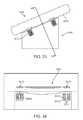
- FIG. 7A through FIG. 7Cillustrate an alternative construction and design for a docking station and a mobile computing device, according to an embodiment.
- FIG. 28 and FIG. 29illustrate side views of how a docking station can be configured in positioning a set of slugs with respect to a receiving surface, under an embodiment.
- FIG. 30illustrates a ferrous ring formed into a region of the back façade of a mobile computing device, under an embodiment.
- FIG. 33illustrates a mobile computing device docked onto a docking station (or other device) using magnetic clasping, under an embodiment.
- a mobile computing deviceand a docking station are provided.
- the docking stationis configured to (i) physically retain the MCD, and (ii) communicate one or more signals to the MCD when the MCD is retained.
- the docking stationis structured to enable the MCD to occupy any one of a plurality of orientations when the MCD is retained on the docking station.
- at least one of the MCD or docking stationis structured to identify an orientation of the MCD as retained on the docking station.
- At least one of the MCD or the docking stationis configured to perform one or more operations that are selected, by either the docking station or the MCD, based at least in part on the identified orientation of the MCD.
- an embodimentincludes an accessory device for a mobile computing device.
- the accessory devicemay include an inductive element, and a signal handling module that is configured to inductively transmit at least one of a power or data signal to another device using the inductive element.
- the accessory devicemay include a first coil to inductively signal at least power to the other device, and a second coil to inductively signal at least data to the other device.
- a docking stationmay be equipped with one or more of (i) an accelerometer and/or (ii) an optical sensor in order to identify the orientation of the MCD.
- the docking stationmay be equipped with magnetic reed and/or Hall effect switches to identify the orientation of the MCD.
- one of the MCD or the docking stationmay be structured to identify the orientation of the MCD and to communicate information that identifies or uses the identified orientation to the other of the MCD or docking station.
- a docking station for a mobile computing deviceincludes a receiving surface that is structured to receive and retain a facade of the mobile computing device.
- the docking stationmay also include a configuration of electrical contacts distributed on the receiving surface to make contact with the facade of the mobile computing device.
- the configuration of electrical contactsmay include two or more electrical contacts that are each positioned to make contact with the corresponding electrical contact on a surface or facade of another device.
- a signal handling componentmay be configured to transmit one or more signals that carry both power and data using electrical contacts distributed on the receiving surface.
- the magnetic component or couplingmay correspond to one or more magnets provided with or beneath a receiving surface of the docking station.
- the ferrous materialmay be provided on the rear facade of the mobile computing device as a plurality of tabs.
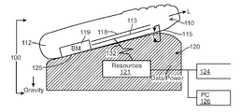
- the signal path 132 that is enabled from the construction of the MCD 110 and dock 120is inductive or transductive.
- the signal path 132may use induction or other transduction to convey signal energy from or between respective signal points of the dock 120 and the MCD 110 .
- the non-continuously (or transductive) signal pathmay be used to carry power and/or data, to and/or from the MCD 110 or dock 120 .
- FIG. 2Ais a representative block diagram of a computer system comprising the MCD 110 and dock 120 , each of which is configured to communicate signals on a continuously conductive signal path, under an embodiment.
- the MCD 110 and dock 120may be mated and retained in a manner described with an embodiment of FIG. 1 .
- An exterior surface 212 , 222 of MCD 110 and dock 120respectively may be in contact as a result of the retention of the MCD on a receiving surface of the dock.
- the exterior surface 212 of MCD 110may correspond to, or be provided by, the exterior facade of the housing shell 112 ( FIG. 1 ).
- a signal source 225 on the dock 120e.g. such as a power inlet 124 in combination with resources 121 ) may generate a signal (e.g.
- FIG. 2Bis a representation of one or more continuously conductive signal path 250 , as extended from or between the dock 120 to the MCD 110 , using conductive elements provided on both devices (such as described with previous embodiments).
- the signal paths 250may carry power and/or information from the dock 120 to the MCD 110 , or alternatively, from the computing device to the station.
- the signal paths 250when provided in the form of power, may be generated from electrical power source 252 and signaled out using conductive elements.
- the circuit elements provided from the dock 120include wiring or circuit elements that terminate as conductive elements 224 on the exterior surface 222 .
- the conductive elements 224may correspond to, for example, metallic elements that terminate electrical leads from a power source of the dock 120 .
- a dockmay be structured to provide conductive elements that are selectively positioned or formed to mate with corresponding conductive elements of the MCD 300 (see FIG. 3 ).
- a dock for supporting the MCD in a manner as describedmay have any of many possible form factors.
- the dockmay extend an arrangement of contact elements that are aligned to make contact surface points 325 on the rear facade 315 of the MCD 300 ( FIG. 3B ).
- electrical contacts formed on the rear façade 315 of the MCD 300may be combined with electrical contacts formed on the rear façade 315 of the MCD 300 .
- the electrical contacts on both the rear façade 315 and the dockmay be surface treated to be rough in order to facilitate retention of the MCD in the docked position.
- While some embodiments described aboveprovide for a conductive signal path between a mobile computing device and a docking station, one or more embodiments provide a non-continuously conductive or transductive signal path to be used to carry power and/or information between the dock and the MCD.
- a non-continuously conductive signal pathmay refer to the ability of a signal to be carried from or between devices, where the signal undergoes transformation from current/voltage form to some other form and back again to current/voltage.
- One embodimentprovide for a signal path that includes an inductive segment to convey one or more signals between the MCD and the dock.
- the inductive conveyance of power and/or data signalsmay be achieved through use of coils, provided on each device that is to be coupled to transmit or receive such signals.
- Various coil configurationsare possible to enable conveyance of power and/or data, either unidirectionally or bi-directionally.
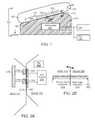
- FIG. 10Cillustrates another implementation in which each of the dock 820 and MCD 810 include two coils.
- power and data coils 922 , 924 on the dock 820may communicate power 921 and data 923 signals to respective coils 932 , 934 on the MCD 810 .
- the power and data communicationsare bi-directional.
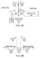
- the power subsystem 1012receives an incoming power signal 1008 from the dock 1020 and distributes the power signal in modified or regulated form to either other components or to the battery for recharge.
- the power signal 1008is signaled through an inductive path from the dock 1020 to the MCD 1010 , in a unidirectional fashion.
- the communication subsystem 1016is configured to communicate with the dock 1020 to receive and/or transmit data 1009 .
- the communication subsystem 1016may include resources to demodulate data carried on the power signal.
- the communication subsystem 1016may use its resources to implement a protocol for retrieving and using credential information (e.g.
- datamay also be combined with the power signal 1009 by modulating the power signal.
- the dock 1020signals data with the power signal 1009 as a preliminary step to establishing a different wireless communication relationship.
- the data signal 1008may be communicated to or from the MCD separate from the power signal.
- the MCD 1010may be configured to enable telephony operations, including enabling the user to answer incoming calls through manipulation of anyone of multiple possible user-interface features present on the MCD.
- the MCD 1010may implement a mode that makes specific programmatically implemented assumptions about call handling.
- the mode of communicationis at least partially wireless.
- a local wireless communication mediumsuch as provided by BLUETOOTH 2.0 or WIRELESS USB
- the dock 1020may serve as an intermediary or pass-through for the personal computer, so as to acquire and pass data to and from the MCD 1010 on behalf of the personal computer.
- the MCD 1010may communicate directly with the personal computer.
- one or both devicesmay assume operations or a role for the media playback. For example, the user may initiate media playback on the MCD 1010 , and the device will then seek to use audio output resources provided on or with (e.g. connected to) the dock 1020 .
- the MCD 1010may use its own display for graphic or video output when outputting the audio. If media playback is initiated and the two devices are separated, media playback may be terminated. In one implementation, separation may be detected when one or both devices detect termination of the power signal. For example, the MCD 1010 may detect that it has stopped receiving power, and then it may communicate this information to the dock 1020 . Alternatively, the MCD 1010 and dock 1020 may each be configured to send confirmation communications until the ‘power-break’ is detected, in which case the combined functionality (such as the media playback) is terminated.
- sub-step 1224provides for paired operations or functionality to be performed. Paired functionality means some level of authentication, trust or credential exchange is initiated and completed, followed by activity on one or both devices under the assumption of authentication or trust.
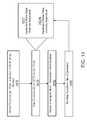
- FIG. 13is a block diagram that illustrates different data exchange operation that may be performed through pairing of docked devices, in accordance with one or more embodiments.
- the MCD 1010when the MCD 1010 is placed in contact to receive the power signal from the dock 1020 , one or both devices are triggered to initiate negotiations for enabling subsequent local wireless communications.
- the subsequent local wireless communicationsmay be performed under established industry protocol (e.g. establishment of BLUETOOTH credentials), requiring passage of certain information or data between two devices before communication may be initiated.
- the credential exchangemay establish the pairing to exist beyond the time the MCD 1010 is removed from the dock 1020 .
- the usermay place the MCD 1010 on the dock 1020 to receive power and/or the credential exchange.
- the usermay then remove the device and continue to wirelessly communicate to or through the dock using the established credentials.
- the docking of the MCD 1010serves as an authentication event that lasts longer than the duration of the MCD being in contact with the dock 1020 .
- one or more embodimentsalso provide that the credential exchange 1344 between the MCD 1010 and the dock 1020 may carry over to other uses of the MCD. Specifically, an embodiment may require the two devices to be docked when credential exchange/pairing is established. An assumption may be realized that the user is physically present, thus the use of the MCD 1010 with the dock 1020 may provide a form of self-authentication.
- the dock 1020may be connected or paired with another computing device or machine. Credentials, permissions, authorizations or other pairing relationship data may be transferred from the dock 1020 to the MCD 1010 .
- this form of authenticationmay enable the MCD to (i) communicate with that other machine or computer directly, (ii) perform some operation that requires a certain permission or right, or (iii) access a guarded resource (e.g. decrypt files, provide password substitute etc.).
- a guarded resourcee.g. decrypt files, provide password substitute etc.
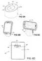
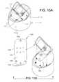
- FIG. 15A through FIG. 15Cillustrate implementations of structural surface features that may be provided with the MCD and/or the dock, under different embodiments of the invention.
- the dock 1510may be configured to include a platform 1512 (or receiving surface; see also embodiments of FIG. 7B or FIG. 7C ) or shelf so as to receive and support the MCD 1520 in an electrically engaged manner.
- the platform 1512may be of any shape, such as elliptical or circular, as shown in FIG. 15A .
- the platform 1512may extend from a body 1505 to be partially upright or vertical.
- One type of mechanical features to support the MCD 1520 in multiple orientationsare template structures 1522 , 1523 .
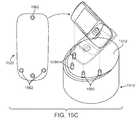
- FIG. 15B and FIG. 15Cillustrate another implementation in which surface features may be used to mechanically retain the MCD 1520 on the platform 1512 of the dock 1510 .
- an embodiment such as shownmay provide that the back face 1562 of the MCD 1520 (or alternatively the platform 1512 of the dock 1510 ) includes surface protrusions 1532 .
- the platform 1512 (or alternatively the back façade 1562 )may include aligned retention recessions 1534 .
- Two or more sets of protrusions 1532 /recessions 1534may be provided to enable the MCD 1520 to be docked in alternative positions (e.g. portrait or landscape).
- the platform 1512may be configured to include indentations that align to receive corresponding protrusions 1532 on the back face 1562 of the MCD 1520 .
- the back face 1562may include alternative formations to enable the MCD 1520 to be docked in either the landscape or portrait mode.
- the dock 1510includes an arrangement of magnets which retain metal elements in the back face 1562 of the MCD 1520 .
- Embodiments described belowdescribe various other arrangements of magnets which may be combined with one or both devices to retain the two devices in alternating docked positions.
- the MCD 1520may utilize sensors to detect its own position, then configure its operations (and optionally communicate with the dock 1510 ) as to the configuration or operations performed; (ii) the MCD 1520 may use detectors that detect alignment with corresponding elements on the docking station, and based on which detectors make contact, determine its own orientation; (iii) the dock 1510 may detect the MCD's position and communicate the position back to the MCD 1520 ; and/or (iv) the dock 1510 detects information using alignment contacts (see item (ii)) or sensors (e.g. optical sensors) that is then communicated to the MCD 1520 where it is used to detect orientation on the MCD.
- alignment contactssee item (ii)
- sensorse.g. optical sensors
- the MCD 1520may utilize an accelerometer to determine the tilt and thus the position of the device.
- magnetic reed switches or Hall effect switchesmay be provided on the dock to sense the presence and/or orientation of the MCD. Such an implementation may be facilitated when magnets are also used to retain the two devices in the docked position.
- step 1430provides that the MCD's position on the dock may be altered after the device is docked.
- the usermay move the MCD from, for example, the portrait position to the landscape position.
- the MCDmay be moved from the portrait position to 45 degrees of vertical, the landscape position, or one or more positions in between.
- the MCD 1520when the MCD 1520 is docked in a particular orientation, the MCD 1520 may be triggered to perform or display information such as: (i) Internet or network content, such as stock, weather or news; (ii) provide a clock; (iii) display slide show of pictures or images; (iv) display calendar or task lists or event list; or (v) provide generic personalized displays by them, such as for ‘work’, ‘personal’ or ‘finance’.
- state informationmay be implemented, such as by way of reducing the power consumption and/or switching select components of the device off. For example, when the device is docked, one or more components (display, cellular radio, GPS radio) may be switched on (or alternatively off). As mentioned, the position of the MCD 1520 on the dock may determine the function, state or mode of operation that the device has.
- the MCDis configured to use the signal handler resource 1650 to convey and/or receive some data that enables subsequent communications between the devices.
- This datamay include credential data 1652 , which enable subsequent wireless communications using, for example, a local wireless communication link via one of the local wireless communication ports 1630 .
- the credential data 1652may be stored within a portion of the memory resources and made available to the processing resources for inclusion or use with functions performed by the signal handling resource 1650 .
- the signal handling resource 1650is capable of communicating at least some of the credential data through a modulated power signal.
- the signal handling resourceis capable of recognizing or using the credential data 1652 to identify and pair with the dock.
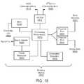
- FIG. 18is a simplified block diagram of a dock, under an embodiment.
- the dock 1800may correspond to any of the docks described with other embodiments herein.
- a dock as describedmay be used to implement (depending on the embodiment) a conductive or inductive signal path for communicating power and data with a MCD such as described with FIG. 17 .
- the dock 1800includes processing resources 1810 , a signal handler 1820 , memory resources 1830 , and a power resource 1840 .
- the dock 1800may also include one or more communication ports, including a wireless communication port 1842 and/or one or more wireline communication ports 1844 .
- the dockmay send or receive wireless communications 1811 with the MCD.
- Such communicationsmay accomplish various tasks or operations, including (i) synchronization or communication of data files or records 1861 (e.g. synchronize contacts and emails), (ii) establish a paired relationship with the MCD for subsequent operations using credential information 1863 and device communications 1864 , (iii) establish a paired relationship between the MCD and a third computing device connected to the dock (e.g. enable BLUETOOTH or wireline communication with attached personal computer), (iv) serve as a pass-through or data interface with another device (e.g. television of display screen) by forwarding communications 1862 to a third computer (e.g. personal computer or laptop), and/or (iv) exchange of data to share or provide resources or extend functionality of the MCD (e.g. enable playback of media data 1865 residing on the device by routing audio to speakers connected to dock).
- a third computing devicee.g. enable BLUETOOTH or wireline communication with attached personal computer
- magnetic clasping between an MCD and any of the dock or any other devicemay be performed to simply retain the MCD against the dock (e.g. cradle) or other accessory device (e.g. modem).
- the docke.g. cradle
- accessory devicee.g. modem
- some embodimentsprovide that magnetic clasping, as described with any of the embodiments herein may be used to simply retain one device against the other.
- some embodimentsinclude distributing magnets and ferrous materials between MCD and dock (or other coupled devices) in order to enable retention of the two devices together.
- Various configurations for implementing magnets and ferrous material on the MCD and/or dockmay be utilized in accordance with embodiments described with, for example, FIG. 19-34 .
- a portable or MCD onto a dockmay be passive or active, depending on design and implementation.
- gravityis the primary force that holds the device in position, so that appropriate surfaces on the MCD are in contact with corresponding points of the dock.
- embodimentsprovide for the retention of the MCD and the dock to be effective using any one or more of (i) mechanical retention using support structures and/frictional pressures (with gravity or other forces), (ii) mechanical clasping, and/or (iii) magnetic fields or clamping.
- magnetsmay be combined with the dock (or optionally with the MCD) in order to clasp the two devices together when docked.
- Such magnetic claspingmay offer several benefits, including the ability to enable the orientation by which the MCD is docked to be altered. As described elsewhere, some embodiments provide that the orientation of the MCD on the dock may be used to affect the state, mode or functionality of the MCD and/or dock. Additionally, magnetic clasping amongst the devices may enhance the ability to enable connector-less signal exchange between the MCD and the dock, as the MCD may simply be placed on the dock for retention. Thus, under one implementation, when place within a certain allowable area, the magnets will pull the device into the proper position for the connector-less signal exchange and charging.
- FIG. 19depicts a configuration for a back face of a MCD, under an embodiment.
- a housing surface (i.e. back façade 1915 ) of the MCDis provided with material that is attracted to magnetic materials.
- the back façade 1915 of the MCDincludes ferrous tabs 1912 .
- the ferrous tabs 1912may be provided on or near an exterior of the rear façade 1915 .
- some ferrous materialmay be combined with a thickness of the housing shell, or glued to an exterior of the housing shell.
- Various spatial arrangementsmay be provided for the ferrous tabs 1912 .
- the distribution of the ferrous tabs 1912may correspond to various geometric shapes.
- a portion of the back face 1915may include a ferrous layer or thickness.
- conductive signal transmissionmay be enabled between the MCD and the dock.
- the use of the conductive signal pathis enhanced because the magnet coupling provides an active physical retention force between the surfaces of the two devices.
- FIG. 21is a side cross-sectional view of a dock 2000 with magnets 2012 for providing the receiving surface 2010 , under an embodiment.
- the magnets 2012may be provided in apertures or openings 2022 just under the receiving surface 2010 . This enables the receiving surface 2010 to be smooth, while at the same time being able to receive and magnetically retain the MCD when it is dropped on the receiving surface.
- a body 2015 of the dock 2000may align the receiving surface 2010 to receive the back face 1915 of the MCD.
- the receiving surface 2010may be slanted at least partially in a vertical direction, although alternative variations may provide for the receiving surface to be horizontal.
- FIG. 22illustrates one embodiment in which ferrous cups 2050 are provided in connection with the magnets 2012 of the dock, under an embodiment.
- the ferrous cups 2050serve to focus the magnetic fields of the magnets 2012 .
- the focused magnetic fieldsbetter enable the receiving surface 2010 to align with the back face 1915 of the MCD.
- FIG. 25depicts the façade 1915 of the MCD with representative electronic components 2310 and 2312 , according to an embodiment.
- the representative electronic components 2310 and 2312may be embedded at different layers within a housing of the device (underneath the exposed back façade 1915 ).
- the ferrous tabs 1912may be positioned to circumvent the electronic components 2310 , 2312 .
- FIG. 34illustrates an alternative construction for dock 2000 .
- FIG. 34represents a cross-sectional view of the dock 2000 and MCD 1900 along lines A-A, according to one or more embodiments.
- the dock 2000may include magnets 2012 that have a horse-shoe or U-shape.
- individual magnets 2922may include parallel members 2911 that extend upward from a common platform 2913 .
- a docking station in accordance with one or more embodimentsmay be structured to mount to vertical environments, such as walls or windshields of automobiles.
- a docking station or accessory devicemay include suction cups or similar structures to enable the docking station to retain to the vertical surface.
- the accessory deviceincludes magnets, such as described in sections provided above, to magnetically attract to ferrous or like material in the mobile computing device.
- the mobile computing devicemay occupy anyone of many possible orientations, and remain docked through use of relatively strong magnetic forces.
- modules that carry functionality for enabling keyboard or inputs, cameras or image capturing (e.g. video), GPS, or modemsmay be provided in housings that can be coupled to the MCD via a sticky-back configuration, such as shown in FIG. 35 .
- Such embodimentsmay use magnetic clasping to hold the two devices together.
- signal conductione.g. see FIG. 1
- inductive signal transferpower or data
- orientation detectionin a manner described above. Numerous other variations or also possible.
Landscapes
- Engineering & Computer Science (AREA)
- Computer Networks & Wireless Communication (AREA)
- Theoretical Computer Science (AREA)
- Power Engineering (AREA)
- Human Computer Interaction (AREA)
- Signal Processing (AREA)
- Physics & Mathematics (AREA)
- General Engineering & Computer Science (AREA)
- General Physics & Mathematics (AREA)
- Computer Hardware Design (AREA)
- Charge And Discharge Circuits For Batteries Or The Like (AREA)
- Power Sources (AREA)
- Telephone Function (AREA)
- Secondary Cells (AREA)
- Telephone Set Structure (AREA)
Abstract
Description
Claims (16)
Priority Applications (13)
| Application Number | Priority Date | Filing Date | Title |
|---|---|---|---|
| US12/239,656US8385822B2 (en) | 2008-09-26 | 2008-09-26 | Orientation and presence detection for use in configuring operations of computing devices in docked environments |
| US12/455,802US8401469B2 (en) | 2008-09-26 | 2009-06-04 | Shield for use with a computing device that receives an inductive signal transmission |
| US12/478,763US8688037B2 (en) | 2008-09-26 | 2009-06-04 | Magnetic latching mechanism for use in mating a mobile computing device to an accessory device |
| US12/478,766US8712324B2 (en) | 2008-09-26 | 2009-06-04 | Inductive signal transfer system for computing devices |
| PCT/US2009/055928WO2010036501A2 (en) | 2008-09-26 | 2009-09-03 | Orientation and presence detection for use in configuring operations of computing devices in docked environments |
| GB1106194.2AGB2476214B (en) | 2008-09-26 | 2009-09-03 | Orientation and presence detection for use in configuring operations of computing devices in docked environments |
| CN200980137882.3ACN102217201B (en) | 2008-09-26 | 2009-09-03 | Orientation and presence detection for use in configuring operation of a computing device in a docked environment |
| DE112009002333TDE112009002333T5 (en) | 2008-09-26 | 2009-09-03 | Orientation and presence detection for use in configuring computer device operations in docked environments |
| US12/620,478US8527688B2 (en) | 2008-09-26 | 2009-11-17 | Extending device functionality amongst inductively linked devices |
| US12/621,087US8234509B2 (en) | 2008-09-26 | 2009-11-18 | Portable power supply device for mobile computing devices |
| US12/916,388US20110106954A1 (en) | 2008-09-26 | 2010-10-29 | System and method for inductively pairing devices to share data or resources |
| US13/171,878US8850045B2 (en) | 2008-09-26 | 2011-06-29 | System and method for linking and sharing resources amongst devices |
| US13/173,252US8868939B2 (en) | 2008-09-26 | 2011-06-30 | Portable power supply device with outlet connector |
Applications Claiming Priority (1)
| Application Number | Priority Date | Filing Date | Title |
|---|---|---|---|
| US12/239,656US8385822B2 (en) | 2008-09-26 | 2008-09-26 | Orientation and presence detection for use in configuring operations of computing devices in docked environments |
Related Child Applications (3)
| Application Number | Title | Priority Date | Filing Date |
|---|---|---|---|
| US12/478,766Continuation-In-PartUS8712324B2 (en) | 2008-09-26 | 2009-06-04 | Inductive signal transfer system for computing devices |
| US12/478,763Continuation-In-PartUS8688037B2 (en) | 2008-09-26 | 2009-06-04 | Magnetic latching mechanism for use in mating a mobile computing device to an accessory device |
| US12/455,802Continuation-In-PartUS8401469B2 (en) | 2008-09-26 | 2009-06-04 | Shield for use with a computing device that receives an inductive signal transmission |
Publications (2)
| Publication Number | Publication Date |
|---|---|
| US20100081473A1 US20100081473A1 (en) | 2010-04-01 |
| US8385822B2true US8385822B2 (en) | 2013-02-26 |
Family
ID=42058027
Family Applications (1)
| Application Number | Title | Priority Date | Filing Date |
|---|---|---|---|
| US12/239,656Expired - Fee RelatedUS8385822B2 (en) | 2008-09-26 | 2008-09-26 | Orientation and presence detection for use in configuring operations of computing devices in docked environments |
Country Status (5)
| Country | Link |
|---|---|
| US (1) | US8385822B2 (en) |
| CN (1) | CN102217201B (en) |
| DE (1) | DE112009002333T5 (en) |
| GB (1) | GB2476214B (en) |
| WO (1) | WO2010036501A2 (en) |
Cited By (23)
| Publication number | Priority date | Publication date | Assignee | Title |
|---|---|---|---|---|
| US20090212637A1 (en)* | 2008-02-22 | 2009-08-27 | Access Business Group International Llc | Magnetic positioning for inductive coupling |
| WO2010078557A2 (en) | 2009-01-05 | 2010-07-08 | Palm, Inc. | Interior connector scheme for accessorizing a mobile computing device with a removeable housing segment |
| US20110018498A1 (en)* | 2007-12-21 | 2011-01-27 | Soar Roger J | Vehicle seat inductive charger and data transmitter |
| US20120001589A1 (en)* | 2010-06-30 | 2012-01-05 | Ming-Hsiang Yeh | Bidirectional wireless charging/discharging device |
| US20120013294A1 (en)* | 2010-07-19 | 2012-01-19 | Ming-Hsiang Yeh | Enclosure bidirectional wireless charging/discharging device |
| US20120013295A1 (en)* | 2010-07-19 | 2012-01-19 | Ming-Hsiang Yeh | Bidirectional wireless charging/discharging device |
| US20120112553A1 (en)* | 2010-11-04 | 2012-05-10 | Access Business Group International Llc | Wireless power system and method with improved alignment |
| US20130080676A1 (en)* | 2011-09-26 | 2013-03-28 | Bytec Group Limited | Wireless Data Input System |
| US20130200843A1 (en)* | 2012-02-06 | 2013-08-08 | Canon Kabushiki Kaisha | Electronic apparatus, control method and recording medium |
| US8872628B2 (en) | 2011-04-01 | 2014-10-28 | Qualcomm Incorporated | Document with inductive charging and data storage and transmission |
| US20150016051A1 (en)* | 2013-07-15 | 2015-01-15 | Toshiba Global Commerce Solutions Holdings Corporation | Display assembly having graduated magnetic fastening characteristics |
| US20150084585A1 (en)* | 2013-09-26 | 2015-03-26 | The Charles Stark Draper Laboratory, Inc. | Smart implant battery charger |
| US20150099462A1 (en)* | 2013-10-03 | 2015-04-09 | Blackberry Limited | Nfc-capable holder for mobile communications device |
| US9055438B2 (en) | 2009-01-01 | 2015-06-09 | Qualcomm Incorporated | Exchanging data based upon device proximity and credentials |
| US9225392B2 (en) | 2011-03-09 | 2015-12-29 | Qualcomm Incorporated | Flat power coil for wireless charging applications |
| US20160116183A1 (en)* | 2014-10-27 | 2016-04-28 | Lennox Industries Inc. | Magnetically mounted wall thermostat |
| US9472971B2 (en) | 2007-12-21 | 2016-10-18 | Cynetic Designs Ltd. | Wireless inductive charging of weapon system energy source |
| US20160359355A1 (en)* | 2015-06-02 | 2016-12-08 | Voyetra Turtle Beach, Inc. | Headset Wireless Charging Dock |
| US20180248406A1 (en)* | 2015-09-02 | 2018-08-30 | Samsung Electronics Co., Ltd. | Cradle for wireless charging and electronic device applied to same |
| US10439449B2 (en) | 2016-08-10 | 2019-10-08 | Microsoft Technology Licensing, Llc | Coupling device modules for inductive data transmission |
| US10969825B2 (en)* | 2017-06-22 | 2021-04-06 | Hewlett-Packard Development Company, L.P. | Magnetic members of docking devices |
| US11784502B2 (en) | 2014-03-04 | 2023-10-10 | Scramoge Technology Limited | Wireless charging and communication board and wireless charging and communication device |
| US12429242B2 (en)* | 2022-01-18 | 2025-09-30 | Computime Electronics (Shenzhen) Co. Ltd. | Thermostat with detachable dial control |
Families Citing this family (177)
| Publication number | Priority date | Publication date | Assignee | Title |
|---|---|---|---|---|
| US7065658B1 (en) | 2001-05-18 | 2006-06-20 | Palm, Incorporated | Method and apparatus for synchronizing and recharging a connector-less portable computer system |
| US20130198867A1 (en)* | 2011-12-09 | 2013-08-01 | Z124 | A Docking Station for Portable Devices Providing Authorized Power Transfer and Facility Access |
| US8169185B2 (en) | 2006-01-31 | 2012-05-01 | Mojo Mobility, Inc. | System and method for inductive charging of portable devices |
| US7952322B2 (en) | 2006-01-31 | 2011-05-31 | Mojo Mobility, Inc. | Inductive power source and charging system |
| US11201500B2 (en) | 2006-01-31 | 2021-12-14 | Mojo Mobility, Inc. | Efficiencies and flexibilities in inductive (wireless) charging |
| US7948208B2 (en) | 2006-06-01 | 2011-05-24 | Mojo Mobility, Inc. | Power source, charging system, and inductive receiver for mobile devices |
| US11329511B2 (en) | 2006-06-01 | 2022-05-10 | Mojo Mobility Inc. | Power source, charging system, and inductive receiver for mobile devices |
| TW200816772A (en)* | 2006-09-27 | 2008-04-01 | Compal Communications Inc | Portable electronic apparatus |
| US20110050164A1 (en) | 2008-05-07 | 2011-03-03 | Afshin Partovi | System and methods for inductive charging, and improvements and uses thereof |
| USD640976S1 (en) | 2008-08-28 | 2011-07-05 | Hewlett-Packard Development Company, L.P. | Support structure and/or cradle for a mobile computing device |
| USD660228S1 (en) | 2008-08-28 | 2012-05-22 | Hewlett-Packard Development Company, L.P. | Power supply unit |
| US8527688B2 (en)* | 2008-09-26 | 2013-09-03 | Palm, Inc. | Extending device functionality amongst inductively linked devices |
| US8850045B2 (en) | 2008-09-26 | 2014-09-30 | Qualcomm Incorporated | System and method for linking and sharing resources amongst devices |
| US20110106954A1 (en)* | 2008-09-26 | 2011-05-05 | Manjirnath Chatterjee | System and method for inductively pairing devices to share data or resources |
| US8401469B2 (en)* | 2008-09-26 | 2013-03-19 | Hewlett-Packard Development Company, L.P. | Shield for use with a computing device that receives an inductive signal transmission |
| US8868939B2 (en) | 2008-09-26 | 2014-10-21 | Qualcomm Incorporated | Portable power supply device with outlet connector |
| US8234509B2 (en)* | 2008-09-26 | 2012-07-31 | Hewlett-Packard Development Company, L.P. | Portable power supply device for mobile computing devices |
| US8688037B2 (en)* | 2008-09-26 | 2014-04-01 | Hewlett-Packard Development Company, L.P. | Magnetic latching mechanism for use in mating a mobile computing device to an accessory device |
| US8712324B2 (en) | 2008-09-26 | 2014-04-29 | Qualcomm Incorporated | Inductive signal transfer system for computing devices |
| JP5404003B2 (en)* | 2008-11-07 | 2014-01-29 | キヤノン株式会社 | Image display apparatus and control method thereof |
| US9083686B2 (en)* | 2008-11-12 | 2015-07-14 | Qualcomm Incorporated | Protocol for program during startup sequence |
| US11344140B2 (en) | 2009-01-10 | 2022-05-31 | Mobile Tech, Inc. | Display for hand-held electronics |
| US10373456B2 (en) | 2009-01-10 | 2019-08-06 | Mobile Tech, Inc. | Display for hand-held electronics |
| US20140159898A1 (en) | 2010-06-21 | 2014-06-12 | Mobile Technologies, Inc. | Display for hand-held electronics |
| US7873772B2 (en)* | 2009-02-17 | 2011-01-18 | Tyco Healthcare Group Lp | Portable and programmable medical device |
| JP2010278941A (en)* | 2009-06-01 | 2010-12-09 | Panasonic Corp | Communications system |
| US20100308187A1 (en)* | 2009-06-04 | 2010-12-09 | Pi-Fen Lin | Integrated magnetic device and a magnetic board thereof |
| US8095191B2 (en)* | 2009-07-06 | 2012-01-10 | Motorola Mobility, Inc. | Detection and function of seven self-supported orientations in a portable device |
| US8954001B2 (en)* | 2009-07-21 | 2015-02-10 | Qualcomm Incorporated | Power bridge circuit for bi-directional wireless power transmission |
| US9395827B2 (en)* | 2009-07-21 | 2016-07-19 | Qualcomm Incorporated | System for detecting orientation of magnetically coupled devices |
| US8437695B2 (en)* | 2009-07-21 | 2013-05-07 | Hewlett-Packard Development Company, L.P. | Power bridge circuit for bi-directional inductive signaling |
| US8395547B2 (en) | 2009-08-27 | 2013-03-12 | Hewlett-Packard Development Company, L.P. | Location tracking for mobile computing device |
| US8755815B2 (en) | 2010-08-31 | 2014-06-17 | Qualcomm Incorporated | Use of wireless access point ID for position determination |
| US20110099507A1 (en) | 2009-10-28 | 2011-04-28 | Google Inc. | Displaying a collection of interactive elements that trigger actions directed to an item |
| USD674391S1 (en) | 2009-11-17 | 2013-01-15 | Hewlett-Packard Development Company, L.P. | Docking station for a computing device |
| US9094054B2 (en)* | 2009-11-30 | 2015-07-28 | Broadcom Corporation | IC controlled wireless power operation and applications thereof including control channel communication configuration |
| USD640216S1 (en)* | 2010-01-22 | 2011-06-21 | Samsung Electronics Co., Ltd. | Mobile phone |
| US8741403B2 (en)* | 2010-03-19 | 2014-06-03 | Tennrich International Corp. | Flexible disposition apparatus |
| US20150212544A1 (en)* | 2010-03-19 | 2015-07-30 | Shih-Hui Chen | Mounting Apparatus For Auxiliary Device |
| US8614560B2 (en)* | 2010-03-26 | 2013-12-24 | Nokia Corporation | Method and apparatus for determining interaction mode |
| JP5440334B2 (en)* | 2010-04-05 | 2014-03-12 | 船井電機株式会社 | Mobile information display terminal |
| US8452877B2 (en)* | 2010-04-28 | 2013-05-28 | Lenovo (Singapore) Pte. Ltd. | Establishing a remote desktop |
| US8364649B2 (en)* | 2010-05-21 | 2013-01-29 | Research In Motion Limited | Apparatus, and associated method, for facilitating synchronization of a wireless device |
| WO2011156768A2 (en) | 2010-06-11 | 2011-12-15 | Mojo Mobility, Inc. | System for wireless power transfer that supports interoperability, and multi-pole magnets for use therewith |
| US8954099B2 (en)* | 2010-06-16 | 2015-02-10 | Qualcomm Incorporated | Layout design of proximity sensors to enable shortcuts |
| US9037407B2 (en)* | 2010-07-12 | 2015-05-19 | Palantir Technologies Inc. | Method and system for determining position of an inertial computing device in a distributed network |
| USD640218S1 (en)* | 2010-07-19 | 2011-06-21 | Motorola Mobility, Inc. | Communication device |
| US8711656B1 (en) | 2010-08-27 | 2014-04-29 | Verifone Systems, Inc. | Sonic fast-sync system and method for bluetooth |
| USD639767S1 (en)* | 2010-09-17 | 2011-06-14 | Motorola Mobility, Inc. | Communication device |
| USD638816S1 (en)* | 2010-09-17 | 2011-05-31 | Fih (Hong Kong) Limited | Mobile phone |
| CN103222319B (en) | 2010-09-29 | 2016-08-10 | 高通股份有限公司 | A kind of method for mobile computing device and mobile computing device |
| US9501292B2 (en)* | 2010-11-30 | 2016-11-22 | Gil Levy | Automatic sleep mode prevention of mobile device in car holder |
| US9542203B2 (en) | 2010-12-06 | 2017-01-10 | Microsoft Technology Licensing, Llc | Universal dock for context sensitive computing device |
| US9124105B2 (en)* | 2010-12-07 | 2015-09-01 | Bryce Robert Gunderman | Wireless charging shelf |
| US8923770B2 (en) | 2010-12-09 | 2014-12-30 | Microsoft Corporation | Cognitive use of multiple regulatory domains |
| USD654457S1 (en)* | 2010-12-10 | 2012-02-21 | Samsung Electronics Co., Ltd. | Mobile phone |
| USD662484S1 (en)* | 2010-12-10 | 2012-06-26 | Cycell Limited | Miniphone |
| EP2652937A1 (en)* | 2010-12-14 | 2013-10-23 | GN Netcom A/S | Docking station for a handheld telecommunication device |
| US8792429B2 (en) | 2010-12-14 | 2014-07-29 | Microsoft Corporation | Direct connection with side channel control |
| US9294545B2 (en) | 2010-12-16 | 2016-03-22 | Microsoft Technology Licensing, Llc | Fast join of peer to peer group with power saving mode |
| US8948382B2 (en) | 2010-12-16 | 2015-02-03 | Microsoft Corporation | Secure protocol for peer-to-peer network |
| US8971841B2 (en) | 2010-12-17 | 2015-03-03 | Microsoft Corporation | Operating system supporting cost aware applications |
| US8760294B2 (en) | 2011-01-05 | 2014-06-24 | Blackberry Limited | Electronic device having an electronic compass adapted to detect when the device is in a holster |
| EP2474878B1 (en)* | 2011-01-05 | 2013-03-20 | Research In Motion Limited | Electronic device having an electronic compass adapted to detect when the device is in a holster |
| US10033718B2 (en)* | 2011-01-05 | 2018-07-24 | Lenovo (Singapore) Pte. Ltd. | Pairing of base and detachable device |
| EP2474877B1 (en)* | 2011-01-05 | 2014-11-19 | BlackBerry Limited | System & method for using magnetometer readings to control electronic devices |
| US9178369B2 (en) | 2011-01-18 | 2015-11-03 | Mojo Mobility, Inc. | Systems and methods for providing positioning freedom, and support of different voltages, protocols, and power levels in a wireless power system |
| US9496732B2 (en) | 2011-01-18 | 2016-11-15 | Mojo Mobility, Inc. | Systems and methods for wireless power transfer |
| US10115520B2 (en) | 2011-01-18 | 2018-10-30 | Mojo Mobility, Inc. | Systems and method for wireless power transfer |
| US11342777B2 (en) | 2011-01-18 | 2022-05-24 | Mojo Mobility, Inc. | Powering and/or charging with more than one protocol |
| CN103384879A (en)* | 2011-02-03 | 2013-11-06 | 泰格斯集团国际公司 | Portable electronic device docking station |
| US8948692B2 (en)* | 2011-02-08 | 2015-02-03 | Qualcomm Incorporated | Graphic notification feedback for indicating inductive coupling amongst devices |
| TWI450075B (en)* | 2011-05-10 | 2014-08-21 | Wistron Corp | Electronic device |
| DE102011101414A1 (en)* | 2011-05-13 | 2012-11-15 | Abb Ag | Electrical installation device with charger and storage for a mobile audio and communication device |
| TWI540408B (en)* | 2011-06-02 | 2016-07-01 | 緯創資通股份有限公司 | Keyboard dock and computer system |
| EP2544330B1 (en)* | 2011-07-07 | 2014-09-10 | BlackBerry Limited | Accessory ID recognition by power cycling |
| US8909955B2 (en) | 2011-07-07 | 2014-12-09 | Blackberry Limited | Method and apparatus for providing characteristics information of a peripheral device to an electronic device by encoding the characteristic information into a power signal |
| EP2732682A1 (en)* | 2011-07-11 | 2014-05-21 | RPT Communications Inc. | Mobile device docking station |
| TW201305801A (en)* | 2011-07-22 | 2013-02-01 | Acer Inc | Power docking station and general transmission interface |
| CN102427378B (en)* | 2011-07-29 | 2015-09-23 | 上海合合信息科技发展有限公司 | Utilize data transmission method and the system of Bluetooth technology and acceleration induction technology |
| CN102427377A (en)* | 2011-07-29 | 2012-04-25 | 上海合合信息科技发展有限公司 | Data transmission method and system for establishing Bluetooth connection by using acceleration sensor |
| US20160072327A1 (en)* | 2011-09-03 | 2016-03-10 | Vieira Systems Inc. | Dock for Portable Electronic Devices |
| CN102999149A (en)* | 2011-09-14 | 2013-03-27 | 宏碁股份有限公司 | Electronic system and power management method |
| EP2582153A1 (en)* | 2011-10-12 | 2013-04-17 | Research In Motion Limited | Portable Electronic Device with Magnetic Audio Interface and Audio Reproduction Accessory Therefor |
| US8873233B2 (en) | 2011-10-28 | 2014-10-28 | Xplore Technologies Corp. | Vehicle dock for ruggedized tablet |
| WO2013087099A1 (en) | 2011-12-14 | 2013-06-20 | Gn Netcom A/S | Headset base with holder for mobile communication device |
| WO2013105005A1 (en) | 2012-01-13 | 2013-07-18 | Koninklijke Philips N.V. | Wireless docking link budget optimization system |
| US9569957B2 (en)* | 2012-03-08 | 2017-02-14 | Htc Corporation | Systems, devices and methods involving device identification |
| US9722447B2 (en) | 2012-03-21 | 2017-08-01 | Mojo Mobility, Inc. | System and method for charging or powering devices, such as robots, electric vehicles, or other mobile devices or equipment |
| US20130271069A1 (en) | 2012-03-21 | 2013-10-17 | Mojo Mobility, Inc. | Systems and methods for wireless power transfer |
| US9368997B2 (en)* | 2012-08-02 | 2016-06-14 | Htc Corporation | Systems involving magnetic attachment for portable electronic devices and related methods |
| EP2708973A1 (en)* | 2012-09-14 | 2014-03-19 | BlackBerry Limited | Multi-orientation stand for a portable electronic device |
| US9414166B2 (en)* | 2012-09-27 | 2016-08-09 | Hewlett-Packard Development Company, L.P. | Wireless peripheral hub device |
| US9647481B2 (en) | 2012-12-04 | 2017-05-09 | Qualcomm Incorporated | Apparatus and methods for docking a dockee with a docking host utilizing a wireless charger in a wireless docking environment |
| US9570925B2 (en) | 2012-12-05 | 2017-02-14 | Nokia Technologies Oy | Apparatus for selectively supporting and charging an electronic device in a portrait position and a landscape position |
| US9760116B2 (en) | 2012-12-05 | 2017-09-12 | Mobile Tech, Inc. | Docking station for tablet device |
| EP2750361B1 (en)* | 2012-12-27 | 2015-10-21 | Nokia Technologies OY | Controlling an application parameter |
| US9837846B2 (en) | 2013-04-12 | 2017-12-05 | Mojo Mobility, Inc. | System and method for powering or charging receivers or devices having small surface areas or volumes |
| WO2015023547A1 (en)* | 2013-08-10 | 2015-02-19 | Hogan Joshua Noel Josh | Head-mounted optical coherence tomography |
| CN103475834B (en)* | 2013-09-29 | 2016-11-02 | 惠州Tcl移动通信有限公司 | A kind of smart mobile phone and external micro-projector thereof |
| US9411446B2 (en)* | 2013-11-04 | 2016-08-09 | Google Technology Holdings LLC | Electronic device with a touch sensor and method for operating the same |
| KR20150067673A (en)* | 2013-12-10 | 2015-06-18 | 엘지전자 주식회사 | Wireless charging device |
| DE102013226342B4 (en)* | 2013-12-18 | 2022-10-13 | Siemens Healthcare Gmbh | medical equipment |
| CN106464688B (en) | 2014-03-31 | 2019-08-13 | 皇家飞利浦有限公司 | Wireless communication system |
| KR102511376B1 (en) | 2014-08-02 | 2023-03-17 | 애플 인크. | Context-specific user interfaces |
| US10452253B2 (en) | 2014-08-15 | 2019-10-22 | Apple Inc. | Weather user interface |
| US9793727B2 (en)* | 2014-10-10 | 2017-10-17 | Samsung-Electro-Mechanics Co., Ltd. | Apparatus for wireless charging |
| US9892628B2 (en) | 2014-10-14 | 2018-02-13 | Logitech Europe S.A. | Method of controlling an electronic device |
| US20160189679A1 (en)* | 2014-10-14 | 2016-06-30 | Logitech Europe S.A | Apparatus and method for controlling interactions with a portable electronic device |
| US9904323B2 (en) | 2014-10-28 | 2018-02-27 | Targus International Llc | Power and data adapter, and related systems and methods |
| KR102348219B1 (en)* | 2014-11-05 | 2022-01-07 | 삼성전자 주식회사 | Detachable Apparatus and Operating Method Thereof |
| US9798380B2 (en)* | 2014-11-13 | 2017-10-24 | Grant & Union Inc. | Modular apparatus and system for reconfigurable user inputs |
| EP3035157A1 (en)* | 2014-12-15 | 2016-06-22 | Thomson Licensing | Method and processing equipment for activating a multi-user mode between mobile devices |
| EP3234729A4 (en) | 2014-12-15 | 2018-08-08 | Targus International LLC | Power and data adapter |
| EP3198359A4 (en)* | 2015-01-23 | 2018-05-30 | Hewlett-Packard Development Company, L.P. | Detecting orientation of a device docked to a docking station |
| US9572104B2 (en) | 2015-02-25 | 2017-02-14 | Microsoft Technology Licensing, Llc | Dynamic adjustment of user experience based on system capabilities |
| WO2016144385A1 (en) | 2015-03-08 | 2016-09-15 | Apple Inc. | Sharing user-configurable graphical constructs |
| US9836083B2 (en) | 2015-03-12 | 2017-12-05 | Flextronics Ap, Llc | Complete wearable ecosystem |
| US9685802B1 (en)* | 2015-04-29 | 2017-06-20 | Verily Life Sciences, LLC | Detection of accessory presence and orientation |
| US20180302116A1 (en)* | 2015-05-15 | 2018-10-18 | Spyder Digital Research Inc. | Removable casing for an electronic device |
| US20160357354A1 (en)* | 2015-06-04 | 2016-12-08 | Apple Inc. | Condition-based activation of a user interface |
| US9916075B2 (en) | 2015-06-05 | 2018-03-13 | Apple Inc. | Formatting content for a reduced-size user interface |
| CN107921317B (en) | 2015-08-20 | 2021-07-06 | 苹果公司 | Movement-based watch faces and complications |
| DE102015216424A1 (en)* | 2015-08-27 | 2017-03-02 | Faurecia Innenraum Systeme Gmbh | Docking station for a mobile electronic device for use in a vehicle interior |
| US20170090516A1 (en)* | 2015-09-25 | 2017-03-30 | Intel Corporation | Docking station |
| WO2017060900A1 (en)* | 2015-10-06 | 2017-04-13 | Benett, Gad | Communicating bracelet |
| US9838064B2 (en) | 2015-10-30 | 2017-12-05 | Essential Products, Inc. | Wireless accessory bus for electronic devices |
| US9921080B2 (en) | 2015-12-18 | 2018-03-20 | Datalogic Ip Tech S.R.L. | Using hall sensors to detect insertion and locking of a portable device in a base |
| US9852098B2 (en)* | 2016-02-26 | 2017-12-26 | Essential Products, Inc. | Systems and techniques for intelligently switching between multiple sources of universal serial bus signals |
| US11170616B2 (en) | 2016-03-16 | 2021-11-09 | Triax Technologies, Inc. | System and interfaces for managing workplace events |
| US10692024B2 (en) | 2016-03-16 | 2020-06-23 | Triax Technologies, Inc. | Wireless mesh network system for monitoring worksite events including detecting false events |
| US11810032B2 (en) | 2016-03-16 | 2023-11-07 | Triax Technologies, Inc. | Systems and methods for low-energy wireless applications using networked wearable sensors |
| US10769562B2 (en) | 2016-03-16 | 2020-09-08 | Triax Technologies, Inc. | Sensor based system and method for authorizing operation of worksite equipment using a locally stored access control list |
| US12175065B2 (en) | 2016-06-10 | 2024-12-24 | Apple Inc. | Context-specific user interfaces for relocating one or more complications in a watch or clock interface |
| US10101770B2 (en) | 2016-07-29 | 2018-10-16 | Mobile Tech, Inc. | Docking system for portable computing device in an enclosure |
| US10705566B2 (en) | 2016-09-09 | 2020-07-07 | Targus International Llc | Systems, methods and devices for native and virtualized video in a hybrid docking station |
| KR102381434B1 (en)* | 2017-03-02 | 2022-03-31 | 삼성전자주식회사 | Wireless charging stand and operation method of electronic device interworking the same |
| US20180314296A1 (en)* | 2017-05-01 | 2018-11-01 | Essential Products, Inc. | Mobile docking station for handheld mobile device |
| DK179412B1 (en) | 2017-05-12 | 2018-06-06 | Apple Inc | Context-Specific User Interfaces |
| CN206875305U (en)* | 2017-05-27 | 2018-01-12 | 厦门东昂光电科技有限公司 | A kind of lighting apparatus of wireless charging |
| US10440544B2 (en) | 2017-07-03 | 2019-10-08 | Essential Products, Inc. | High-frequency motion sensor modules for electronic devices |
| US11231448B2 (en) | 2017-07-20 | 2022-01-25 | Targus International Llc | Systems, methods and devices for remote power management and discovery |
| US10663498B2 (en) | 2017-07-20 | 2020-05-26 | Targus International Llc | Systems, methods and devices for remote power management and discovery |
| US10860516B2 (en)* | 2017-09-28 | 2020-12-08 | Mobile Tech, Inc. | Docking system for portable computing device |
| CA3078386A1 (en)* | 2017-10-12 | 2019-04-18 | Johnson & Johnson Consumer Inc. | Light therapy bandage |
| US11327650B2 (en) | 2018-05-07 | 2022-05-10 | Apple Inc. | User interfaces having a collection of complications |
| NL2021406B1 (en)* | 2018-07-27 | 2020-01-31 | Zens Group B V | Power bank and method for wireless charging |
| DE102018127961A1 (en)* | 2018-11-08 | 2020-05-14 | Steute Technologies Gmbh & Co. Kg | Control unit and pairing procedure for one control unit |
| US11740657B2 (en) | 2018-12-19 | 2023-08-29 | Targus International Llc | Display and docking apparatus for a portable electronic device |
| US11017334B2 (en) | 2019-01-04 | 2021-05-25 | Targus International Llc | Workspace management system utilizing smart docking station for monitoring power consumption, occupancy, and usage displayed via heat maps |
| US11360534B2 (en) | 2019-01-04 | 2022-06-14 | Targus Internatonal Llc | Smart workspace management system |
| US11444485B2 (en) | 2019-02-05 | 2022-09-13 | Mojo Mobility, Inc. | Inductive charging system with charging electronics physically separated from charging coil |
| FR3094103B1 (en)* | 2019-03-18 | 2021-07-23 | Electricite De France | Power consumption display system, charger for such a system, method and program for implementing such a system |
| US11596801B2 (en) | 2019-03-28 | 2023-03-07 | Zoll Medical Corporation | Medical device integrated with portable display and functionality |
| JP6921338B2 (en) | 2019-05-06 | 2021-08-18 | アップル インコーポレイテッドApple Inc. | Limited operation of electronic devices |
| US11131967B2 (en) | 2019-05-06 | 2021-09-28 | Apple Inc. | Clock faces for an electronic device |
| US11960701B2 (en) | 2019-05-06 | 2024-04-16 | Apple Inc. | Using an illustration to show the passing of time |
| CN115562613A (en) | 2019-05-31 | 2023-01-03 | 苹果公司 | User interface for audio media controls |
| DE102019209166B4 (en)* | 2019-06-25 | 2025-04-30 | Siemens Healthineers Ag | Arrangement with a tablet computer unit and a housing part of a medical imaging device |
| BR112022002917A2 (en) | 2019-08-22 | 2022-05-10 | Targus International Llc | Systems and methods for participant-controlled videoconferencing |
| US10852905B1 (en) | 2019-09-09 | 2020-12-01 | Apple Inc. | Techniques for managing display usage |
| JP2022550258A (en) | 2019-09-09 | 2022-12-01 | ターガス インターナショナル エルエルシー | Systems and methods for a docking station removably attachable to a display and docking stand assembly |
| WO2021050186A1 (en) | 2019-09-12 | 2021-03-18 | Zayo Group, Llc | Integrated data and charging station |
| JP7261133B2 (en)* | 2019-09-13 | 2023-04-19 | 株式会社Subaru | vehicle controller |
| CN110994273A (en)* | 2019-12-02 | 2020-04-10 | 深圳市旭联信息技术有限公司 | A split hub |
| US11372659B2 (en) | 2020-05-11 | 2022-06-28 | Apple Inc. | User interfaces for managing user interface sharing |
| US11526256B2 (en) | 2020-05-11 | 2022-12-13 | Apple Inc. | User interfaces for managing user interface sharing |
| DK202070624A1 (en) | 2020-05-11 | 2022-01-04 | Apple Inc | User interfaces related to time |
| US11694590B2 (en) | 2020-12-21 | 2023-07-04 | Apple Inc. | Dynamic user interface with time indicator |
| US11720239B2 (en) | 2021-01-07 | 2023-08-08 | Apple Inc. | Techniques for user interfaces related to an event |
| US12182373B2 (en) | 2021-04-27 | 2024-12-31 | Apple Inc. | Techniques for managing display usage |
| US11921992B2 (en) | 2021-05-14 | 2024-03-05 | Apple Inc. | User interfaces related to time |
| US20220416554A1 (en)* | 2021-06-23 | 2022-12-29 | Tatung Technology Inc. | Charging stand, electronic apparatus, and method for operating charging stand |
| US20230074649A1 (en)* | 2021-09-08 | 2023-03-09 | W. L. Gore & Associates Gmbh | Garment including electronic devices |
| US12073205B2 (en) | 2021-09-14 | 2024-08-27 | Targus International Llc | Independently upgradeable docking stations |
| US20230236547A1 (en) | 2022-01-24 | 2023-07-27 | Apple Inc. | User interfaces for indicating time |
| EP4523062A1 (en)* | 2022-05-10 | 2025-03-19 | Google LLC | Utilization of a force sensor to signal intent to undock a device |
Citations (163)
| Publication number | Priority date | Publication date | Assignee | Title |
|---|---|---|---|---|
| FR2601161A1 (en) | 1986-07-02 | 1988-01-08 | Crouzet Sa | Information processing device |
| US5136414A (en) | 1990-09-07 | 1992-08-04 | Jenkins Vincent C | Permanent magnetic means for positioning a rotatable element to a preselected position |
| US5375226A (en) | 1988-12-29 | 1994-12-20 | Toppan Moore Company, Ltd. | Portable type data entry terminal having a keyboard input device and a graphic input device |
| WO1995003686A1 (en) | 1993-07-23 | 1995-02-02 | Steven James Shattil | Active electromagnetic shielding |
| US5455466A (en) | 1993-07-29 | 1995-10-03 | Dell Usa, L.P. | Inductive coupling system for power and data transfer |
| US5596567A (en) | 1995-03-31 | 1997-01-21 | Motorola, Inc. | Wireless battery charging system |
| US5600225A (en) | 1994-06-30 | 1997-02-04 | Nippon Electric Co | Noncontacting charging device |
| US5666530A (en) | 1992-12-02 | 1997-09-09 | Compaq Computer Corporation | System for automatic synchronization of common file between portable computer and host computer via communication channel selected from a plurality of usable channels there between |
| US5733313A (en) | 1996-08-01 | 1998-03-31 | Exonix Corporation | RF coupled, implantable medical device with rechargeable back-up power source |
| US5760580A (en) | 1994-04-26 | 1998-06-02 | Rso Corporation N.V. | Method for excitation and detection of magnetic elements by a mechanical resonance |
| US5831348A (en) | 1996-06-03 | 1998-11-03 | Mitsubishi Denki Kabushiki Kaisha | Secondary circuit device for wireless transmit-receive system and induction coil for wireless transmit-receive system |
| US5958051A (en) | 1996-11-27 | 1999-09-28 | Sun Microsystems, Inc. | Implementing digital signatures for data streams and data archives |
| US6006274A (en) | 1997-01-30 | 1999-12-21 | 3Com Corporation | Method and apparatus using a pass through personal computer connected to both a local communication link and a computer network for indentifying and synchronizing a preferred computer with a portable computer |
| US6091965A (en) | 1994-06-20 | 2000-07-18 | Microtalk Technologies, Inc. | Low-feedback compact wireless telephone |
| US6138245A (en) | 1999-02-05 | 2000-10-24 | Neopoint, Inc. | System and method for automatic device synchronization |
| US6184651B1 (en) | 2000-03-20 | 2001-02-06 | Motorola, Inc. | Contactless battery charger with wireless control link |
| JP3161388B2 (en) | 1997-11-05 | 2001-04-25 | 日本電気株式会社 | Docking bay system |
| US6266539B1 (en) | 1998-06-12 | 2001-07-24 | Cisco Technology, Inc. | Telephone docking station for personal digital assistant |
| US6330436B1 (en) | 1999-04-30 | 2001-12-11 | Lucent Technologies, Inc. | Enhanced wireless messaging notification system |
| US6389423B1 (en) | 1999-04-13 | 2002-05-14 | Mitsubishi Denki Kabushiki Kaisha | Data synchronization method for maintaining and controlling a replicated data |
| US20020065045A1 (en) | 2000-11-27 | 2002-05-30 | Samsung Electronics Co., Ltd. | Method of information sharing between cellular and local wireless communication systems |
| US6405049B2 (en) | 1997-08-05 | 2002-06-11 | Symbol Technologies, Inc. | Portable data terminal and cradle |
| US20020084698A1 (en) | 2000-11-20 | 2002-07-04 | Kelly Clifford Mark | Electrically isolated power and signal coupler system for a patient connected device |
| US20020103008A1 (en) | 2001-01-29 | 2002-08-01 | Rahn Michael D. | Cordless communication between PDA and host computer using cradle |
| US6436299B1 (en) | 1999-06-21 | 2002-08-20 | Amway Corporation | Water treatment system with an inductively coupled ballast |
| US6445936B1 (en) | 1999-11-16 | 2002-09-03 | Agere Systems Guardian Corp. | Low power consumption quick charge for wireless device |
| US6452197B1 (en) | 1997-11-07 | 2002-09-17 | Applied Materials, Inc. | Ion implantation apparatus and method of implanting ions to prevent charge build up on a substrate |
| US6501364B1 (en) | 2001-06-15 | 2002-12-31 | City University Of Hong Kong | Planar printed-circuit-board transformers with effective electromagnetic interference (EMI) shielding |
| US6510424B1 (en) | 1999-10-22 | 2003-01-21 | International Business Machines Corporation | Electronic notification agent |
| US6532152B1 (en) | 1998-11-16 | 2003-03-11 | Intermec Ip Corp. | Ruggedized hand held computer |
| US20030092389A1 (en) | 2001-03-16 | 2003-05-15 | Hiroyuki Morimoto | Personal digital assistant, wireless communication system, and method of establishing link |
| US20030214255A1 (en) | 1999-06-21 | 2003-11-20 | Baarman David W. | Inductively powered apparatus |
| US20030233455A1 (en) | 2002-06-14 | 2003-12-18 | Mike Leber | Distributed file sharing system |
| US6671700B1 (en) | 2000-05-23 | 2003-12-30 | Palm Source, Inc. | Method and apparatus for parallel execution of conduits during simultaneous synchronization of databases |
| US6673250B2 (en) | 1999-06-21 | 2004-01-06 | Access Business Group International Llc | Radio frequency identification system for a fluid treatment system |
| US6731071B2 (en) | 1999-06-21 | 2004-05-04 | Access Business Group International Llc | Inductively powered lamp assembly |
| US20040088012A1 (en) | 2002-10-30 | 2004-05-06 | Kroll Mark W. | Implantable stimulation device with isolating system for minimizing magnetic induction |
| US20040130915A1 (en) | 1999-06-21 | 2004-07-08 | Baarman David W. | Adaptive inductive power supply with communication |
| US20040130916A1 (en) | 1999-06-21 | 2004-07-08 | Baarman David W. | Adaptive inductive power supply |
| US20040150934A1 (en) | 2003-02-04 | 2004-08-05 | Baarman David W. | Adapter |
| US6795110B1 (en) | 1999-06-15 | 2004-09-21 | Philip Kossin | Weatherproof and watertight digital electronic camera, including a solid or fluid-filled digital camera operating at great depths |
| US6803744B1 (en) | 1999-11-01 | 2004-10-12 | Anthony Sabo | Alignment independent and self aligning inductive power transfer system |
| US6806649B2 (en) | 2002-02-19 | 2004-10-19 | Access Business Group International Llc | Starter assembly for a gas discharge lamp |
| US6810405B1 (en) | 1998-08-18 | 2004-10-26 | Starfish Software, Inc. | System and methods for synchronizing data between multiple datasets |
| WO2004098079A1 (en) | 2003-04-25 | 2004-11-11 | Apple Computer Inc. | Media player system |
| US6825620B2 (en) | 1999-06-21 | 2004-11-30 | Access Business Group International Llc | Inductively coupled ballast circuit |
| US20040259499A1 (en) | 2001-07-18 | 2004-12-23 | Haruo Oba | Communication system and method |
| US20050007067A1 (en) | 1999-06-21 | 2005-01-13 | Baarman David W. | Vehicle interface |
| US6850986B1 (en) | 2001-03-21 | 2005-02-01 | Palm Source, Inc. | Method and system for implementing URL scheme proxies on a computer system |
| US20050030160A1 (en) | 2003-04-17 | 2005-02-10 | Goren David P. | Multimode wireless local area network/radio frequency identification asset tag |
| CN1592197A (en) | 2003-09-01 | 2005-03-09 | 台均实业有限公司 | Method for authentication between client device and local client application or remote network service |
| WO2005024865A2 (en) | 2003-09-08 | 2005-03-17 | Splashpower Limited | Inductive power transfer units having flux shields |
| US6888438B2 (en) | 2001-06-15 | 2005-05-03 | City University Of Hong Kong | Planar printed circuit-board transformers with effective electromagnetic interference (EMI) shielding |
| US6892052B2 (en) | 2002-03-26 | 2005-05-10 | Nokia Corporation | Radio frequency identification (RF-ID) based discovery for short range radio communication |
| US20050186903A1 (en) | 2004-01-21 | 2005-08-25 | Airspan Networks, Inc. | Handling transfer of management data to and from a telecommunications unit of a telecommunications system |
| GB2389720B (en) | 2002-06-10 | 2005-09-07 | Univ City Hong Kong | Planar inductive battery charger |
| GB2399466B (en) | 2003-03-10 | 2005-11-16 | Univ City Hong Kong | Battery charging system |
| US6975198B2 (en) | 2003-02-04 | 2005-12-13 | Access Business Group International Llc | Inductive coil assembly |
| US6986051B2 (en) | 2000-04-13 | 2006-01-10 | International Business Machines Corporation | Method and system for controlling and filtering files using a virus-free certificate |
| US20060041420A1 (en) | 2004-06-30 | 2006-02-23 | Threshold Corporation | Method and apparatus for configuring a network appliance |
| US20060061958A1 (en) | 2004-09-17 | 2006-03-23 | Mark Solomon | Portable computer docking station |
| GB2389767B (en) | 2002-06-10 | 2006-04-19 | Univ City Hong Kong | Apparatus for energy transfer by induction |
| US20060094405A1 (en) | 2004-10-29 | 2006-05-04 | Dupont Pierre B | Mobile station service applications using service kiosk with transponder |
| US20060123055A1 (en) | 2004-12-07 | 2006-06-08 | Paul Atkinson | Device and method for selectively controlling the utility of a target |
| US7065658B1 (en) | 2001-05-18 | 2006-06-20 | Palm, Incorporated | Method and apparatus for synchronizing and recharging a connector-less portable computer system |
| US20060132045A1 (en) | 2004-12-17 | 2006-06-22 | Baarman David W | Heating system and heater |
| US20060145660A1 (en) | 2004-12-30 | 2006-07-06 | Black Greg R | Method and apparatus for near field communications |
| US20060183462A1 (en) | 2005-02-11 | 2006-08-17 | Nokia Corporation | Managing an access account using personal area networks and credentials on a mobile device |
| US20060229027A1 (en) | 2005-03-30 | 2006-10-12 | Sbc Knowledge Ventures Lp | Method and apparatus for provisioning a device |
| US20060258289A1 (en) | 2005-05-12 | 2006-11-16 | Robin Dua | Wireless media system and player and method of operation |
| US7149473B1 (en) | 1999-01-15 | 2006-12-12 | Nokia Corporation | Interface |
| US7164255B2 (en) | 2002-06-10 | 2007-01-16 | City University Of Hong Kong | Inductive battery charger system with primary transformer windings formed in a multi-layer structure |
| US20070024238A1 (en) | 2005-07-27 | 2007-02-01 | Nokia Corporation | Mobile charging |
| US20070035917A1 (en) | 2005-08-09 | 2007-02-15 | Apple Computer, Inc. | Methods and apparatuses for docking a portable electronic device that has a planar like configuration and that operates in multiple orientations |
| US20070077965A1 (en) | 2005-10-05 | 2007-04-05 | Patrick Fox | Portable docking station for cell phone |
| US7202783B2 (en) | 2001-12-18 | 2007-04-10 | Intel Corporation | Method and system for identifying when a first device is within a physical range of a second device |
| US20070120752A1 (en) | 2005-11-30 | 2007-05-31 | Nobuaki Takasu | Information processing apparatus, information processing system and radio communication control method |
| US7236742B2 (en) | 2001-06-18 | 2007-06-26 | Brigham Young University | System and method for wireless data transfer for a mobile unit |
| US7248017B2 (en) | 2002-05-13 | 2007-07-24 | Spashpower Limited | Portable contact-less power transfer devices and rechargeable batteries |
| US20070182367A1 (en) | 2006-01-31 | 2007-08-09 | Afshin Partovi | Inductive power source and charging system |
| US20070188284A1 (en) | 2003-02-26 | 2007-08-16 | Dobbs John M | Shielded power coupling device |
| US7262700B2 (en) | 2005-03-10 | 2007-08-28 | Microsoft Corporation | Inductive powering surface for powering portable devices |
| US7271569B2 (en) | 2004-09-21 | 2007-09-18 | Motorola Inc. | Contact less charger with alignment indicator |
| US7286880B2 (en) | 2003-10-02 | 2007-10-23 | Medtronic, Inc. | System and method for transcutaneous energy transfer achieving high efficiency |
| US20070246546A1 (en) | 2006-04-20 | 2007-10-25 | Yuko Yoshida | Information Processing Terminal, IC Card, Portable Communication Device, Wireless Communication Method, and Program |
| US20070255435A1 (en) | 2005-03-28 | 2007-11-01 | Sound Id | Personal Sound System Including Multi-Mode Ear Level Module with Priority Logic |
| US20070290654A1 (en) | 2006-06-14 | 2007-12-20 | Assaf Govari | Inductive charging of tools on surgical tray |
| US7331793B2 (en) | 2005-12-16 | 2008-02-19 | Motorola, Inc. | Magnetic connector |
| WO2008033670A2 (en) | 2006-09-11 | 2008-03-20 | Apple Inc. | Highly portable media devices |
| WO2008044875A1 (en) | 2006-10-10 | 2008-04-17 | Ls Cable, Ltd. | Rechargeable power supply, battery device, contact-less charger systems and method for charging rechargeable battery cell |
| US7375492B2 (en) | 2003-12-12 | 2008-05-20 | Microsoft Corporation | Inductively charged battery pack |
| US7382636B2 (en) | 2005-10-14 | 2008-06-03 | Access Business Group International Llc | System and method for powering a load |
| US20080133918A1 (en) | 2006-12-04 | 2008-06-05 | Samsung Electronics Co., Ltd. | Method and apparatus for transmitting data using authentication |
| US7385357B2 (en) | 1999-06-21 | 2008-06-10 | Access Business Group International Llc | Inductively coupled ballast circuit |
| KR100836634B1 (en) | 2006-10-24 | 2008-06-10 | 주식회사 한림포스텍 | Portable terminal using a contactless charger, a battery pack for charging and a contactless charger for wireless data communication and power transmission |
| US7392059B2 (en) | 2001-05-14 | 2008-06-24 | Innovision Research & Technology Plc | Electrical devices |
| US20080196086A1 (en) | 2007-02-09 | 2008-08-14 | Sony Corporation, A Japanese Corporation | Method and apparatus for authorizing a communication interface |
| US7414380B2 (en) | 2004-09-21 | 2008-08-19 | Lear Corporation | Apparatus for inductively recharging batteries of a portable convenience device |
| US20080231537A1 (en) | 2007-03-19 | 2008-09-25 | Ahmadreza Rofougaran | Method and system for fm transmit and fm receive using a transformer as a duplexer |
| KR100863420B1 (en) | 2007-06-28 | 2008-10-14 | (주)케이티에프테크놀로지스 | How to pair between Bluetooth devices |
| US20080269927A1 (en) | 2007-04-30 | 2008-10-30 | Szolyga Thomas H | Playback of audio information through a wireless docking station |
| US7446672B2 (en) | 2005-03-24 | 2008-11-04 | M&Fc Holding, Llc | Method and apparatus for coupling a meter register to an automatic meter reading communication device |
| WO2008133806A1 (en) | 2007-04-23 | 2008-11-06 | Eastman Kodak Company | Charging display system |
| US20080278894A1 (en) | 2007-05-11 | 2008-11-13 | Miradia Inc. | Docking station for projection display applications |
| US7454170B2 (en) | 2003-08-08 | 2008-11-18 | Koninklijke Philips Electronics N.V. | Unidirectional power and bi-directional data transfer over a single inductive coupling |
| US7462951B1 (en) | 2004-08-11 | 2008-12-09 | Access Business Group International Llc | Portable inductive power station |
| US7471200B2 (en) | 2005-06-30 | 2008-12-30 | Nokia Corporation | RFID optimized capability negotiation |
| US7471986B2 (en) | 2004-02-20 | 2008-12-30 | Cardiac Pacemakers, Inc. | System and method for transmitting energy to and establishing a communications network with one or more implanted devices |
| US20090001941A1 (en) | 2007-06-29 | 2009-01-01 | Microsoft Corporation | Inductive Powering Surface for Powering Portable Devices |
| US20090001932A1 (en) | 2007-06-29 | 2009-01-01 | Seiko Epson Corporation | Power transmission control device, power transmission device, non-contact power transmission system, and electronic instrument |
| US20090008148A1 (en) | 2007-07-03 | 2009-01-08 | Shinko Electric Industries Co., Ltd. | Inductor built-in wiring board having shield function |
| US7495414B2 (en) | 2005-07-25 | 2009-02-24 | Convenient Power Limited | Rechargeable battery circuit and structure for compatibility with a planar inductive charging platform |
| US20090069869A1 (en) | 2007-09-11 | 2009-03-12 | Advanced Bionics Corporation | Rotating field inductive data telemetry and power transfer in an implantable medical device system |
| US7509432B1 (en) | 2004-11-22 | 2009-03-24 | Palmsource, Inc. | Method and system for implementing URL scheme proxies on a computer system |
| US20090088077A1 (en) | 2005-04-11 | 2009-04-02 | Innovision Research & Technology Plc | Communications Apparatus |
| US20090096413A1 (en) | 2006-01-31 | 2009-04-16 | Mojo Mobility, Inc. | System and method for inductive charging of portable devices |
| US7521890B2 (en) | 2005-12-27 | 2009-04-21 | Power Science Inc. | System and method for selective transfer of radio frequency power |
| US20090106567A1 (en) | 2007-10-17 | 2009-04-23 | Access Business Group International Llc | Laptop and portable electronic device wireless power supply systems |
| WO2009057771A1 (en) | 2007-11-01 | 2009-05-07 | Meidensha Corporation | Electronic authentication device, electronic authentication system, electronic authentication method and its program |
| US20090170433A1 (en) | 2007-12-28 | 2009-07-02 | Mark Rhodes | Inductive communications system |
| US7565108B2 (en) | 2002-03-26 | 2009-07-21 | Nokia Corporation | Radio frequency identification (RF-ID) based discovery for short range radio communication with reader device having transponder functionality |
| US20090193500A1 (en) | 2008-01-30 | 2009-07-30 | Kent Griffin | Near field communication activation and authorization |
| US20090199219A1 (en) | 2008-02-06 | 2009-08-06 | Broadcom Corporation | Operating system for a computing device with handheld and extended computing units |
| US20090203399A1 (en) | 2008-02-08 | 2009-08-13 | Broadcom Corporation | Integrated circuit with communication and rfid functions and methods for use therewith |
| US7576657B2 (en) | 2006-03-22 | 2009-08-18 | Symbol Technologies, Inc. | Single frequency low power RFID device |
| US20090212637A1 (en) | 2008-02-22 | 2009-08-27 | Access Business Group International Llc | Magnetic positioning for inductive coupling |
| US20090212737A1 (en) | 2008-02-25 | 2009-08-27 | L & P Property Management Company | Inductively coupled shelving and storage containers |
| US7589285B2 (en) | 2003-09-12 | 2009-09-15 | Nippon Steel & Sumikin Coated Sheet Corporation | Magnetic shield panel |
| US20090233623A1 (en) | 2008-03-14 | 2009-09-17 | Johnson William J | System and method for location based exchanges of data facilitating distributed locational applications |
| US20090322278A1 (en) | 2008-06-27 | 2009-12-31 | Microsoft Corporation | Docking station for electronic device |
| WO2010005324A1 (en) | 2008-07-07 | 2010-01-14 | Powerbyproxi Limited | A contactless power receiver and method of operation |
| US20100007449A1 (en) | 2008-04-03 | 2010-01-14 | Tait Towers Inc. | Magnetically coupled device |
| US20100021176A1 (en) | 2006-11-16 | 2010-01-28 | Integration Associates Inc. | Apparatus and Method for Near-Field Communication |
| US20100023204A1 (en) | 2008-07-24 | 2010-01-28 | Basir Otman A | Power management system |
| US20100045269A1 (en) | 2001-03-16 | 2010-02-25 | Lafranchise Jeffrey R | Methods and apparatus to detect location and orientation in an inductive system |
| US20100070219A1 (en) | 2007-03-22 | 2010-03-18 | Powermat Ltd | Efficiency monitor for inductive power transmission |
| US20100076524A1 (en) | 2003-10-02 | 2010-03-25 | Medtronic, Inc. | Inductively rechargeable external energy source, charger, system and method for a transcutaneous inductive charger for an implantable medical device |
| US20100081483A1 (en) | 2008-09-26 | 2010-04-01 | Manjirnath Chatterjee | Shield for use with a computing device that receives an inductive signal transmission |
| US20100083012A1 (en) | 2008-09-26 | 2010-04-01 | Mark Corbridge | Inductive Signal Transfer System for Computing Devices |
| US20100081377A1 (en) | 2008-09-26 | 2010-04-01 | Manjirnath Chatterjee | Magnetic latching mechanism for use in mating a mobile computing device to an accessory device |
| US20100093279A1 (en) | 2008-10-14 | 2010-04-15 | Qualcomm Incorporated | Electronic devices for communication utilizing energy detection and/or frequency synthesis |
| US20100121965A1 (en) | 2008-11-12 | 2010-05-13 | Palm, Inc. | Protocol for Program during Startup Sequence |
| US20100131691A1 (en) | 2008-09-26 | 2010-05-27 | Manjirnath Chatterjee | Extending device functionality amongst inductively linked devices |
| WO2010062198A1 (en) | 2008-11-26 | 2010-06-03 | Auckland Uniservices Limited | Bi-directional inductive power transfer |
| US20100146308A1 (en) | 2008-09-26 | 2010-06-10 | Richard Gioscia | Portable power supply device for mobile computing devices |
| WO2010068062A2 (en) | 2008-12-12 | 2010-06-17 | 주식회사 한림포스텍 | Contactless power transmission device |
| US7743151B2 (en) | 2004-08-05 | 2010-06-22 | Cardiac Pacemakers, Inc. | System and method for providing digital data communications over a wireless intra-body network |
| US20100156193A1 (en) | 2008-12-23 | 2010-06-24 | Mark Rhodes | Inductively coupled data and power transfer system and apparatus |
| US7751810B1 (en) | 2006-03-21 | 2010-07-06 | Nextel Communications Inc. | System and method for transmitting information to subscriber communication units at events |
| US20100174801A1 (en) | 2007-09-03 | 2010-07-08 | Nxp B.V. | Method of and device for transferring content |
| US20100172090A1 (en) | 2009-01-05 | 2010-07-08 | Manjirnath Chatterjee | Interior connector scheme for accessorizing a mobile computing device with a removeable housing segment |
| US20100194336A1 (en) | 2007-10-18 | 2010-08-05 | Powermat Ltd. | Inductively chargeable audio devices |
| US20100198453A1 (en) | 2009-02-02 | 2010-08-05 | Apple Inc. | Systems and Methods for Integrating a Portable Electronic Device with a Bicycle |
| WO2010091269A1 (en) | 2009-02-06 | 2010-08-12 | Baylor College Of Medicine | Real-time magnetic dipole detection and tracking |
| US20100211785A1 (en) | 2009-02-13 | 2010-08-19 | Samsung Electronics Co., Ltd. | System and method for automatic wireless connection between a portable terminal and a digital device |
| US7791311B2 (en) | 2005-10-24 | 2010-09-07 | Samsung Electronics Co., Ltd. | Apparatus and method of wirelessly sharing power by inductive method |
| US7800044B1 (en) | 2007-11-09 | 2010-09-21 | Dp Technologies, Inc. | High ambient motion environment detection eliminate accidental activation of a device |
| US20100250986A1 (en) | 2009-03-27 | 2010-09-30 | Motorola, Inc. | Method and Device for Improving Battery Life of a Mobile Computing Device |
| US20100283599A1 (en) | 2005-10-13 | 2010-11-11 | Dung Ma | Power management for wireless devices |
| US7855529B2 (en) | 2008-07-16 | 2010-12-21 | ConvenientPower HK Ltd. | Inductively powered sleeve for mobile electronic device |
| US20110076941A1 (en) | 2009-09-30 | 2011-03-31 | Ebay Inc. | Near field communication and network data/product transfer |
| US8026693B2 (en) | 2007-10-18 | 2011-09-27 | Wi.U, Llc | Induction charger for portable battery-powered devices |
| US20120077432A1 (en) | 2010-09-23 | 2012-03-29 | Research In Motion Limited | Mobile wireless communications device establishing wireless communication links based upon near field communication and related methods |
Family Cites Families (2)
| Publication number | Priority date | Publication date | Assignee | Title |
|---|---|---|---|---|
| US20060253638A1 (en)* | 2005-05-03 | 2006-11-09 | Eastman Kodak Company | System and method for enabling printing and charging of a mobile capture device via a docking device |
| CN101150308B (en)* | 2006-09-21 | 2011-01-19 | 林泰宏 | Contact sensing device, method and application thereof |
- 2008
- 2008-09-26USUS12/239,656patent/US8385822B2/ennot_activeExpired - Fee Related
- 2009
- 2009-09-03WOPCT/US2009/055928patent/WO2010036501A2/enactiveApplication Filing
- 2009-09-03DEDE112009002333Tpatent/DE112009002333T5/ennot_activeWithdrawn
- 2009-09-03CNCN200980137882.3Apatent/CN102217201B/ennot_activeExpired - Fee Related
- 2009-09-03GBGB1106194.2Apatent/GB2476214B/ennot_activeExpired - Fee Related
Patent Citations (186)
| Publication number | Priority date | Publication date | Assignee | Title |
|---|---|---|---|---|
| FR2601161A1 (en) | 1986-07-02 | 1988-01-08 | Crouzet Sa | Information processing device |
| US5375226A (en) | 1988-12-29 | 1994-12-20 | Toppan Moore Company, Ltd. | Portable type data entry terminal having a keyboard input device and a graphic input device |
| US5136414A (en) | 1990-09-07 | 1992-08-04 | Jenkins Vincent C | Permanent magnetic means for positioning a rotatable element to a preselected position |
| US5666530A (en) | 1992-12-02 | 1997-09-09 | Compaq Computer Corporation | System for automatic synchronization of common file between portable computer and host computer via communication channel selected from a plurality of usable channels there between |
| WO1995003686A1 (en) | 1993-07-23 | 1995-02-02 | Steven James Shattil | Active electromagnetic shielding |
| US5455466A (en) | 1993-07-29 | 1995-10-03 | Dell Usa, L.P. | Inductive coupling system for power and data transfer |
| US5760580A (en) | 1994-04-26 | 1998-06-02 | Rso Corporation N.V. | Method for excitation and detection of magnetic elements by a mechanical resonance |
| US6091965A (en) | 1994-06-20 | 2000-07-18 | Microtalk Technologies, Inc. | Low-feedback compact wireless telephone |
| US5600225A (en) | 1994-06-30 | 1997-02-04 | Nippon Electric Co | Noncontacting charging device |
| US5596567A (en) | 1995-03-31 | 1997-01-21 | Motorola, Inc. | Wireless battery charging system |
| US5831348A (en) | 1996-06-03 | 1998-11-03 | Mitsubishi Denki Kabushiki Kaisha | Secondary circuit device for wireless transmit-receive system and induction coil for wireless transmit-receive system |
| US5733313A (en) | 1996-08-01 | 1998-03-31 | Exonix Corporation | RF coupled, implantable medical device with rechargeable back-up power source |
| US5958051A (en) | 1996-11-27 | 1999-09-28 | Sun Microsystems, Inc. | Implementing digital signatures for data streams and data archives |
| US6006274A (en) | 1997-01-30 | 1999-12-21 | 3Com Corporation | Method and apparatus using a pass through personal computer connected to both a local communication link and a computer network for indentifying and synchronizing a preferred computer with a portable computer |
| US6405049B2 (en) | 1997-08-05 | 2002-06-11 | Symbol Technologies, Inc. | Portable data terminal and cradle |
| JP3161388B2 (en) | 1997-11-05 | 2001-04-25 | 日本電気株式会社 | Docking bay system |
| US6452197B1 (en) | 1997-11-07 | 2002-09-17 | Applied Materials, Inc. | Ion implantation apparatus and method of implanting ions to prevent charge build up on a substrate |
| US6266539B1 (en) | 1998-06-12 | 2001-07-24 | Cisco Technology, Inc. | Telephone docking station for personal digital assistant |
| US6810405B1 (en) | 1998-08-18 | 2004-10-26 | Starfish Software, Inc. | System and methods for synchronizing data between multiple datasets |
| US6532152B1 (en) | 1998-11-16 | 2003-03-11 | Intermec Ip Corp. | Ruggedized hand held computer |
| US7149473B1 (en) | 1999-01-15 | 2006-12-12 | Nokia Corporation | Interface |
| US6138245A (en) | 1999-02-05 | 2000-10-24 | Neopoint, Inc. | System and method for automatic device synchronization |
| US6389423B1 (en) | 1999-04-13 | 2002-05-14 | Mitsubishi Denki Kabushiki Kaisha | Data synchronization method for maintaining and controlling a replicated data |
| US6330436B1 (en) | 1999-04-30 | 2001-12-11 | Lucent Technologies, Inc. | Enhanced wireless messaging notification system |
| US6795110B1 (en) | 1999-06-15 | 2004-09-21 | Philip Kossin | Weatherproof and watertight digital electronic camera, including a solid or fluid-filled digital camera operating at great depths |
| US20040130916A1 (en) | 1999-06-21 | 2004-07-08 | Baarman David W. | Adaptive inductive power supply |
| US20050007067A1 (en) | 1999-06-21 | 2005-01-13 | Baarman David W. | Vehicle interface |
| US7126450B2 (en) | 1999-06-21 | 2006-10-24 | Access Business Group International Llc | Inductively powered apparatus |
| US20050127850A1 (en) | 1999-06-21 | 2005-06-16 | Baarman David W. | Inductively powered apparatus |
| US6436299B1 (en) | 1999-06-21 | 2002-08-20 | Amway Corporation | Water treatment system with an inductively coupled ballast |
| US20050127849A1 (en) | 1999-06-21 | 2005-06-16 | Baarman David W. | Inductively powered apparatus |
| US20030214255A1 (en) | 1999-06-21 | 2003-11-20 | Baarman David W. | Inductively powered apparatus |
| US20050122059A1 (en) | 1999-06-21 | 2005-06-09 | Baarman David W. | Inductively powered apparatus |
| US20050122058A1 (en) | 1999-06-21 | 2005-06-09 | Baarman David W. | Inductively powered apparatus |
| US6673250B2 (en) | 1999-06-21 | 2004-01-06 | Access Business Group International Llc | Radio frequency identification system for a fluid treatment system |
| US6731071B2 (en) | 1999-06-21 | 2004-05-04 | Access Business Group International Llc | Inductively powered lamp assembly |
| US20050116650A1 (en) | 1999-06-21 | 2005-06-02 | Baarman David W. | Method of manufacturing a lamp assembly |
| US20040130915A1 (en) | 1999-06-21 | 2004-07-08 | Baarman David W. | Adaptive inductive power supply with communication |
| US7118240B2 (en) | 1999-06-21 | 2006-10-10 | Access Business Group International Llc | Inductively powered apparatus |
| US20050093475A1 (en) | 1999-06-21 | 2005-05-05 | Kuennen Roy W. | Inductively coupled ballast circuit |
| US7385357B2 (en) | 1999-06-21 | 2008-06-10 | Access Business Group International Llc | Inductively coupled ballast circuit |
| US6831417B2 (en) | 1999-06-21 | 2004-12-14 | Access Business Group International Llc | Method of manufacturing a lamp assembly |
| US6825620B2 (en) | 1999-06-21 | 2004-11-30 | Access Business Group International Llc | Inductively coupled ballast circuit |
| US6812645B2 (en) | 1999-06-21 | 2004-11-02 | Access Business Group International Llc | Inductively powered lamp assembly |
| US6510424B1 (en) | 1999-10-22 | 2003-01-21 | International Business Machines Corporation | Electronic notification agent |
| US6803744B1 (en) | 1999-11-01 | 2004-10-12 | Anthony Sabo | Alignment independent and self aligning inductive power transfer system |
| US6445936B1 (en) | 1999-11-16 | 2002-09-03 | Agere Systems Guardian Corp. | Low power consumption quick charge for wireless device |
| US6184651B1 (en) | 2000-03-20 | 2001-02-06 | Motorola, Inc. | Contactless battery charger with wireless control link |
| US6986051B2 (en) | 2000-04-13 | 2006-01-10 | International Business Machines Corporation | Method and system for controlling and filtering files using a virus-free certificate |
| US6671700B1 (en) | 2000-05-23 | 2003-12-30 | Palm Source, Inc. | Method and apparatus for parallel execution of conduits during simultaneous synchronization of databases |
| US6917163B2 (en) | 2000-06-12 | 2005-07-12 | Access Business Group International Llc | Inductively powered lamp assembly |
| US20020084698A1 (en) | 2000-11-20 | 2002-07-04 | Kelly Clifford Mark | Electrically isolated power and signal coupler system for a patient connected device |
| US20020065045A1 (en) | 2000-11-27 | 2002-05-30 | Samsung Electronics Co., Ltd. | Method of information sharing between cellular and local wireless communication systems |
| US20020103008A1 (en) | 2001-01-29 | 2002-08-01 | Rahn Michael D. | Cordless communication between PDA and host computer using cradle |
| US20100045269A1 (en) | 2001-03-16 | 2010-02-25 | Lafranchise Jeffrey R | Methods and apparatus to detect location and orientation in an inductive system |
| US7313364B2 (en) | 2001-03-16 | 2007-12-25 | Mitsubishi Denki Kabushiki Kaisha | Personal digital assistant, wireless communication system, and method of establishing link |
| US20030092389A1 (en) | 2001-03-16 | 2003-05-15 | Hiroyuki Morimoto | Personal digital assistant, wireless communication system, and method of establishing link |
| US6850986B1 (en) | 2001-03-21 | 2005-02-01 | Palm Source, Inc. | Method and system for implementing URL scheme proxies on a computer system |
| US7392059B2 (en) | 2001-05-14 | 2008-06-24 | Innovision Research & Technology Plc | Electrical devices |
| US7065658B1 (en) | 2001-05-18 | 2006-06-20 | Palm, Incorporated | Method and apparatus for synchronizing and recharging a connector-less portable computer system |
| US6888438B2 (en) | 2001-06-15 | 2005-05-03 | City University Of Hong Kong | Planar printed circuit-board transformers with effective electromagnetic interference (EMI) shielding |
| US6501364B1 (en) | 2001-06-15 | 2002-12-31 | City University Of Hong Kong | Planar printed-circuit-board transformers with effective electromagnetic interference (EMI) shielding |
| US7236742B2 (en) | 2001-06-18 | 2007-06-26 | Brigham Young University | System and method for wireless data transfer for a mobile unit |
| US20040259499A1 (en) | 2001-07-18 | 2004-12-23 | Haruo Oba | Communication system and method |
| US7202783B2 (en) | 2001-12-18 | 2007-04-10 | Intel Corporation | Method and system for identifying when a first device is within a physical range of a second device |
| US6806649B2 (en) | 2002-02-19 | 2004-10-19 | Access Business Group International Llc | Starter assembly for a gas discharge lamp |
| US20040222751A1 (en) | 2002-02-19 | 2004-11-11 | Mollema Scott A. | Starter assembly for a gas discharge lamp |
| US7565108B2 (en) | 2002-03-26 | 2009-07-21 | Nokia Corporation | Radio frequency identification (RF-ID) based discovery for short range radio communication with reader device having transponder functionality |
| US6892052B2 (en) | 2002-03-26 | 2005-05-10 | Nokia Corporation | Radio frequency identification (RF-ID) based discovery for short range radio communication |
| US7248017B2 (en) | 2002-05-13 | 2007-07-24 | Spashpower Limited | Portable contact-less power transfer devices and rechargeable batteries |
| GB2389720B (en) | 2002-06-10 | 2005-09-07 | Univ City Hong Kong | Planar inductive battery charger |
| US7576514B2 (en) | 2002-06-10 | 2009-08-18 | Cityu Research Limited | Planar inductive battery charging system |
| US7164255B2 (en) | 2002-06-10 | 2007-01-16 | City University Of Hong Kong | Inductive battery charger system with primary transformer windings formed in a multi-layer structure |
| GB2389767B (en) | 2002-06-10 | 2006-04-19 | Univ City Hong Kong | Apparatus for energy transfer by induction |
| US20030233455A1 (en) | 2002-06-14 | 2003-12-18 | Mike Leber | Distributed file sharing system |
| US20040088012A1 (en) | 2002-10-30 | 2004-05-06 | Kroll Mark W. | Implantable stimulation device with isolating system for minimizing magnetic induction |
| US20040232845A1 (en) | 2003-02-04 | 2004-11-25 | Baarman David W. | Inductive coil assembly |
| US20040150934A1 (en) | 2003-02-04 | 2004-08-05 | Baarman David W. | Adapter |
| US6975198B2 (en) | 2003-02-04 | 2005-12-13 | Access Business Group International Llc | Inductive coil assembly |
| US7116200B2 (en) | 2003-02-04 | 2006-10-03 | Access Business Group International Llc | Inductive coil assembly |
| US7132918B2 (en) | 2003-02-04 | 2006-11-07 | Access Business Group International Llc | Inductive coil assembly |
| US20070188284A1 (en) | 2003-02-26 | 2007-08-16 | Dobbs John M | Shielded power coupling device |
| GB2399466B (en) | 2003-03-10 | 2005-11-16 | Univ City Hong Kong | Battery charging system |
| US20050030160A1 (en) | 2003-04-17 | 2005-02-10 | Goren David P. | Multimode wireless local area network/radio frequency identification asset tag |
| WO2004098079A1 (en) | 2003-04-25 | 2004-11-11 | Apple Computer Inc. | Media player system |
| US7454170B2 (en) | 2003-08-08 | 2008-11-18 | Koninklijke Philips Electronics N.V. | Unidirectional power and bi-directional data transfer over a single inductive coupling |
| CN1592197A (en) | 2003-09-01 | 2005-03-09 | 台均实业有限公司 | Method for authentication between client device and local client application or remote network service |
| WO2005024865A2 (en) | 2003-09-08 | 2005-03-17 | Splashpower Limited | Inductive power transfer units having flux shields |
| US20070064406A1 (en) | 2003-09-08 | 2007-03-22 | Beart Pilgrim G W | Inductive power transfer units having flux shields |
| US7589285B2 (en) | 2003-09-12 | 2009-09-15 | Nippon Steel & Sumikin Coated Sheet Corporation | Magnetic shield panel |
| US7286880B2 (en) | 2003-10-02 | 2007-10-23 | Medtronic, Inc. | System and method for transcutaneous energy transfer achieving high efficiency |
| US20100076524A1 (en) | 2003-10-02 | 2010-03-25 | Medtronic, Inc. | Inductively rechargeable external energy source, charger, system and method for a transcutaneous inductive charger for an implantable medical device |
| US7375492B2 (en) | 2003-12-12 | 2008-05-20 | Microsoft Corporation | Inductively charged battery pack |
| US20050186903A1 (en) | 2004-01-21 | 2005-08-25 | Airspan Networks, Inc. | Handling transfer of management data to and from a telecommunications unit of a telecommunications system |
| US7471986B2 (en) | 2004-02-20 | 2008-12-30 | Cardiac Pacemakers, Inc. | System and method for transmitting energy to and establishing a communications network with one or more implanted devices |
| US20060041420A1 (en) | 2004-06-30 | 2006-02-23 | Threshold Corporation | Method and apparatus for configuring a network appliance |
| US7743151B2 (en) | 2004-08-05 | 2010-06-22 | Cardiac Pacemakers, Inc. | System and method for providing digital data communications over a wireless intra-body network |
| US7462951B1 (en) | 2004-08-11 | 2008-12-09 | Access Business Group International Llc | Portable inductive power station |
| US20060061958A1 (en) | 2004-09-17 | 2006-03-23 | Mark Solomon | Portable computer docking station |
| US7414380B2 (en) | 2004-09-21 | 2008-08-19 | Lear Corporation | Apparatus for inductively recharging batteries of a portable convenience device |
| US7271569B2 (en) | 2004-09-21 | 2007-09-18 | Motorola Inc. | Contact less charger with alignment indicator |
| US20060094405A1 (en) | 2004-10-29 | 2006-05-04 | Dupont Pierre B | Mobile station service applications using service kiosk with transponder |
| US7509432B1 (en) | 2004-11-22 | 2009-03-24 | Palmsource, Inc. | Method and system for implementing URL scheme proxies on a computer system |
| US20060123055A1 (en) | 2004-12-07 | 2006-06-08 | Paul Atkinson | Device and method for selectively controlling the utility of a target |
| US20060132045A1 (en) | 2004-12-17 | 2006-06-22 | Baarman David W | Heating system and heater |
| US20060145660A1 (en) | 2004-12-30 | 2006-07-06 | Black Greg R | Method and apparatus for near field communications |
| US20060183462A1 (en) | 2005-02-11 | 2006-08-17 | Nokia Corporation | Managing an access account using personal area networks and credentials on a mobile device |
| US7262700B2 (en) | 2005-03-10 | 2007-08-28 | Microsoft Corporation | Inductive powering surface for powering portable devices |
| US7446672B2 (en) | 2005-03-24 | 2008-11-04 | M&Fc Holding, Llc | Method and apparatus for coupling a meter register to an automatic meter reading communication device |
| US20070255435A1 (en) | 2005-03-28 | 2007-11-01 | Sound Id | Personal Sound System Including Multi-Mode Ear Level Module with Priority Logic |
| US20060229027A1 (en) | 2005-03-30 | 2006-10-12 | Sbc Knowledge Ventures Lp | Method and apparatus for provisioning a device |
| US20090088077A1 (en) | 2005-04-11 | 2009-04-02 | Innovision Research & Technology Plc | Communications Apparatus |
| US20060258289A1 (en) | 2005-05-12 | 2006-11-16 | Robin Dua | Wireless media system and player and method of operation |
| US7471200B2 (en) | 2005-06-30 | 2008-12-30 | Nokia Corporation | RFID optimized capability negotiation |
| US7495414B2 (en) | 2005-07-25 | 2009-02-24 | Convenient Power Limited | Rechargeable battery circuit and structure for compatibility with a planar inductive charging platform |
| US20070024238A1 (en) | 2005-07-27 | 2007-02-01 | Nokia Corporation | Mobile charging |
| US20070035917A1 (en) | 2005-08-09 | 2007-02-15 | Apple Computer, Inc. | Methods and apparatuses for docking a portable electronic device that has a planar like configuration and that operates in multiple orientations |
| US7352567B2 (en) | 2005-08-09 | 2008-04-01 | Apple Inc. | Methods and apparatuses for docking a portable electronic device that has a planar like configuration and that operates in multiple orientations |
| US20100177476A1 (en) | 2005-08-09 | 2010-07-15 | Apple Inc. | Methods and apparatuses for docking a portable electronic device that has a planar like configuration and that operates in multiple orientations |
| US20070077965A1 (en) | 2005-10-05 | 2007-04-05 | Patrick Fox | Portable docking station for cell phone |
| US20100283599A1 (en) | 2005-10-13 | 2010-11-11 | Dung Ma | Power management for wireless devices |
| US7382636B2 (en) | 2005-10-14 | 2008-06-03 | Access Business Group International Llc | System and method for powering a load |
| US7791311B2 (en) | 2005-10-24 | 2010-09-07 | Samsung Electronics Co., Ltd. | Apparatus and method of wirelessly sharing power by inductive method |
| US20070120752A1 (en) | 2005-11-30 | 2007-05-31 | Nobuaki Takasu | Information processing apparatus, information processing system and radio communication control method |
| US7331793B2 (en) | 2005-12-16 | 2008-02-19 | Motorola, Inc. | Magnetic connector |
| US7521890B2 (en) | 2005-12-27 | 2009-04-21 | Power Science Inc. | System and method for selective transfer of radio frequency power |
| US20090096413A1 (en) | 2006-01-31 | 2009-04-16 | Mojo Mobility, Inc. | System and method for inductive charging of portable devices |
| US20070182367A1 (en) | 2006-01-31 | 2007-08-09 | Afshin Partovi | Inductive power source and charging system |
| US7751810B1 (en) | 2006-03-21 | 2010-07-06 | Nextel Communications Inc. | System and method for transmitting information to subscriber communication units at events |
| US7576657B2 (en) | 2006-03-22 | 2009-08-18 | Symbol Technologies, Inc. | Single frequency low power RFID device |
| US20070246546A1 (en) | 2006-04-20 | 2007-10-25 | Yuko Yoshida | Information Processing Terminal, IC Card, Portable Communication Device, Wireless Communication Method, and Program |
| US20070290654A1 (en) | 2006-06-14 | 2007-12-20 | Assaf Govari | Inductive charging of tools on surgical tray |
| WO2008033670A2 (en) | 2006-09-11 | 2008-03-20 | Apple Inc. | Highly portable media devices |
| WO2008044875A1 (en) | 2006-10-10 | 2008-04-17 | Ls Cable, Ltd. | Rechargeable power supply, battery device, contact-less charger systems and method for charging rechargeable battery cell |
| KR100836634B1 (en) | 2006-10-24 | 2008-06-10 | 주식회사 한림포스텍 | Portable terminal using a contactless charger, a battery pack for charging and a contactless charger for wireless data communication and power transmission |
| US20100021176A1 (en) | 2006-11-16 | 2010-01-28 | Integration Associates Inc. | Apparatus and Method for Near-Field Communication |
| US20080133918A1 (en) | 2006-12-04 | 2008-06-05 | Samsung Electronics Co., Ltd. | Method and apparatus for transmitting data using authentication |
| US20080196086A1 (en) | 2007-02-09 | 2008-08-14 | Sony Corporation, A Japanese Corporation | Method and apparatus for authorizing a communication interface |
| US20080231537A1 (en) | 2007-03-19 | 2008-09-25 | Ahmadreza Rofougaran | Method and system for fm transmit and fm receive using a transformer as a duplexer |
| US20100070219A1 (en) | 2007-03-22 | 2010-03-18 | Powermat Ltd | Efficiency monitor for inductive power transmission |
| WO2008133806A1 (en) | 2007-04-23 | 2008-11-06 | Eastman Kodak Company | Charging display system |
| US20080269927A1 (en) | 2007-04-30 | 2008-10-30 | Szolyga Thomas H | Playback of audio information through a wireless docking station |
| US20080278894A1 (en) | 2007-05-11 | 2008-11-13 | Miradia Inc. | Docking station for projection display applications |
| KR100863420B1 (en) | 2007-06-28 | 2008-10-14 | (주)케이티에프테크놀로지스 | How to pair between Bluetooth devices |
| US8026694B2 (en) | 2007-06-29 | 2011-09-27 | Seiko Epson Corporation | Power transmission control device, power transmission device, non-contact power transmission system, and electronic instrument |
| US20090001941A1 (en) | 2007-06-29 | 2009-01-01 | Microsoft Corporation | Inductive Powering Surface for Powering Portable Devices |
| US20090001932A1 (en) | 2007-06-29 | 2009-01-01 | Seiko Epson Corporation | Power transmission control device, power transmission device, non-contact power transmission system, and electronic instrument |
| US20090008148A1 (en) | 2007-07-03 | 2009-01-08 | Shinko Electric Industries Co., Ltd. | Inductor built-in wiring board having shield function |
| US20100174801A1 (en) | 2007-09-03 | 2010-07-08 | Nxp B.V. | Method of and device for transferring content |
| US20090069869A1 (en) | 2007-09-11 | 2009-03-12 | Advanced Bionics Corporation | Rotating field inductive data telemetry and power transfer in an implantable medical device system |
| US20090106567A1 (en) | 2007-10-17 | 2009-04-23 | Access Business Group International Llc | Laptop and portable electronic device wireless power supply systems |
| US8026693B2 (en) | 2007-10-18 | 2011-09-27 | Wi.U, Llc | Induction charger for portable battery-powered devices |
| US20100194336A1 (en) | 2007-10-18 | 2010-08-05 | Powermat Ltd. | Inductively chargeable audio devices |
| WO2009057771A1 (en) | 2007-11-01 | 2009-05-07 | Meidensha Corporation | Electronic authentication device, electronic authentication system, electronic authentication method and its program |
| US7800044B1 (en) | 2007-11-09 | 2010-09-21 | Dp Technologies, Inc. | High ambient motion environment detection eliminate accidental activation of a device |
| US20090170433A1 (en) | 2007-12-28 | 2009-07-02 | Mark Rhodes | Inductive communications system |
| US20090193500A1 (en) | 2008-01-30 | 2009-07-30 | Kent Griffin | Near field communication activation and authorization |
| US20090199219A1 (en) | 2008-02-06 | 2009-08-06 | Broadcom Corporation | Operating system for a computing device with handheld and extended computing units |
| US20090203399A1 (en) | 2008-02-08 | 2009-08-13 | Broadcom Corporation | Integrated circuit with communication and rfid functions and methods for use therewith |
| US20090212637A1 (en) | 2008-02-22 | 2009-08-27 | Access Business Group International Llc | Magnetic positioning for inductive coupling |
| US20090212737A1 (en) | 2008-02-25 | 2009-08-27 | L & P Property Management Company | Inductively coupled shelving and storage containers |
| US20090233623A1 (en) | 2008-03-14 | 2009-09-17 | Johnson William J | System and method for location based exchanges of data facilitating distributed locational applications |
| US20100007449A1 (en) | 2008-04-03 | 2010-01-14 | Tait Towers Inc. | Magnetically coupled device |
| US20090322278A1 (en) | 2008-06-27 | 2009-12-31 | Microsoft Corporation | Docking station for electronic device |
| WO2010005324A1 (en) | 2008-07-07 | 2010-01-14 | Powerbyproxi Limited | A contactless power receiver and method of operation |
| US7855529B2 (en) | 2008-07-16 | 2010-12-21 | ConvenientPower HK Ltd. | Inductively powered sleeve for mobile electronic device |
| US20100023204A1 (en) | 2008-07-24 | 2010-01-28 | Basir Otman A | Power management system |
| US20100083012A1 (en) | 2008-09-26 | 2010-04-01 | Mark Corbridge | Inductive Signal Transfer System for Computing Devices |
| US20100146308A1 (en) | 2008-09-26 | 2010-06-10 | Richard Gioscia | Portable power supply device for mobile computing devices |
| US20100131691A1 (en) | 2008-09-26 | 2010-05-27 | Manjirnath Chatterjee | Extending device functionality amongst inductively linked devices |
| US20100081377A1 (en) | 2008-09-26 | 2010-04-01 | Manjirnath Chatterjee | Magnetic latching mechanism for use in mating a mobile computing device to an accessory device |
| US20100081483A1 (en) | 2008-09-26 | 2010-04-01 | Manjirnath Chatterjee | Shield for use with a computing device that receives an inductive signal transmission |
| US20100093279A1 (en) | 2008-10-14 | 2010-04-15 | Qualcomm Incorporated | Electronic devices for communication utilizing energy detection and/or frequency synthesis |
| US20100121965A1 (en) | 2008-11-12 | 2010-05-13 | Palm, Inc. | Protocol for Program during Startup Sequence |
| WO2010062198A1 (en) | 2008-11-26 | 2010-06-03 | Auckland Uniservices Limited | Bi-directional inductive power transfer |
| WO2010068062A2 (en) | 2008-12-12 | 2010-06-17 | 주식회사 한림포스텍 | Contactless power transmission device |
| WO2010068062A3 (en) | 2008-12-12 | 2010-09-23 | 주식회사 한림포스텍 | Contactless power transmission device |
| US20100156193A1 (en) | 2008-12-23 | 2010-06-24 | Mark Rhodes | Inductively coupled data and power transfer system and apparatus |
| WO2010077994A2 (en) | 2009-01-05 | 2010-07-08 | Palm, Inc. | Extending device functionality amongst inductively linked devices |
| US20100172090A1 (en) | 2009-01-05 | 2010-07-08 | Manjirnath Chatterjee | Interior connector scheme for accessorizing a mobile computing device with a removeable housing segment |
| US20100198453A1 (en) | 2009-02-02 | 2010-08-05 | Apple Inc. | Systems and Methods for Integrating a Portable Electronic Device with a Bicycle |
| WO2010091269A1 (en) | 2009-02-06 | 2010-08-12 | Baylor College Of Medicine | Real-time magnetic dipole detection and tracking |
| US20100211785A1 (en) | 2009-02-13 | 2010-08-19 | Samsung Electronics Co., Ltd. | System and method for automatic wireless connection between a portable terminal and a digital device |
| US20100250986A1 (en) | 2009-03-27 | 2010-09-30 | Motorola, Inc. | Method and Device for Improving Battery Life of a Mobile Computing Device |
| US20110076941A1 (en) | 2009-09-30 | 2011-03-31 | Ebay Inc. | Near field communication and network data/product transfer |
| US20120077432A1 (en) | 2010-09-23 | 2012-03-29 | Research In Motion Limited | Mobile wireless communications device establishing wireless communication links based upon near field communication and related methods |
Non-Patent Citations (40)
| Title |
|---|
| AdvancedCardSystems, "ACR122U NFC Contactless Smart Card Reader-URL Transfer," available at URL , uploaded Oct. 12, 2010. |
| AdvancedCardSystems, "ACR122U NFC Contactless Smart Card Reader—URL Transfer," available at URL < http://www.youtube.com/watch?v=USImfpCZaTo >, uploaded Oct. 12, 2010. |
| Extended European Search Report, European Application No. 11186983.0, Apr. 24, 2012, pp. 1-15. |
| Final Office Action mailed Dec. 30, 2009 in U.S. Appl. No. 11/430,786. |
| Final Office Action mailed Jan. 8, 2009 in U.S. Appl. No. 11/430,786. |
| Final Office Action mailed Jul. 19, 2010 in U.S. Appl. No. 11/430,786. |
| Final Office Action mailed Jul. 9, 2007 in U.S. Appl. No. 11/430,786. |
| Final Office Action mailed Oct. 25, 2004 in U.S. Appl. No. 09/861,658 10 pgs. |
| Hui et al., "A New Generation of Universal Contactless Battery Charging Platform for Portable Consumer Electronic Equipment," IEEE Trans Power Electronics, 20(3):620-627 (2005). |
| International Search Report and Writen Opinion dated Aug. 31, 2010 in International Application No. PCT/US2010/020054. |
| International Search Report and Written Opinion dated Apr. 20, 2010 in International Application No. PCT/US2009/055928. |
| International Search Report and Written Opinion dated Aug. 20, 2010 in International Application No. PCT/US2009/069847. |
| International Search Report and Written Opinion dated Jul. 21, 2010 in International Application No. PCT/US2009/068328. |
| International Search Report and Written Opinion dated Jul. 28, 2010 in International Application No. PCT/US2009/068332. |
| International Search Report and Written Opinion, International Application No. PCT/US2011/058449, Date of Mailing: May 16, 2012, pp. 1-11. |
| International Search Report and Written Opinion, International Application No. PCT/US2012/024202, Date of Completion: Apr. 26, 2012, Date of Mailing: Apr. 26, 2012, pp. 1-9. |
| Kean, Steven, "Powermat Portable Wireless Charging Mat", pp. 1-12 dwnloaded from http://www.bigbruin.com/content/powermat-1 on Sep. 29, 2010. |
| Liang et al., "An implantable bi-directional wireless transmission system for transcutaneous biological signal recording," Physiol. Meas. 26:83-97 (2005). |
| Mel B. W. et al., "Tablet: Personal Computer in the Year 2000", Communications of the Association for Computing machinery, New Your, NY vol. 31, No. 6, Jun. 1, 1988, 639-646 XP000047633ISSN: 0001-0782. |
| Non-Final Office Action mailed Apr. 22, 2004 in U.S. Appl. No. 09/861,658 7 pgs. |
| Non-Final Office Action mailed Apr. 7, 2005 in U.S. Appl. No. 09/861,658 11 pgs. |
| Non-Final Office Action mailed Jan. 25, 2008 in U.S. Appl. No. 11/430,786. |
| Non-Final Office Action mailed Jul. 25, 2008 in U.S. Appl. No. 11/430,786. |
| Non-Final Office Action mailed Jun. 11, 2009 in U.S. Appl. No. 11/430,786. |
| Non-Final Office Action mailed Mar. 24, 2010 in U.S. Appl. No. 11/430,786. |
| Non-Final Office Action mailed Nov. 3, 2010 in U.S. Appl. No. 12/478,616 12 pgs. |
| Non-Final Office Action mailed Oct. 5, 2006 in U.S. Appl. No. 11/430,786. |
| Non-Final Office Action mailed Sep. 30, 2010 in U.S. Appl. No. 11/430,786 7 pgs. |
| Notice of Allowance mailed Jan. 9, 2006 in U.S. Appl. No. 09/861,658 12 pgs. |
| Opticon Users manual DWT 7133, Nov. 2000. |
| U.S. Appl. No. 11/430,786, filed May 8, 2006, Baraban et al. |
| U.S. Appl. No. 12/628,401, filed Dec. 1, 2009, Chatterjee. |
| U.S. Appl. No. 12/840,241, filed Jul. 20, 2010, Chatterjee. |
| U.S. Appl. No. 12/841,001, filed Jul. 21, 2010, Chatterjee. |
| U.S. Appl. No. 12/916,388, filed Oct. 29, 2010, Chatterjee et al. |
| U.S. Appl. No. 12/975,335, filed Dec. 21, 2010, Oh et al. |
| U.S. Appl. No. 12/987,940, filed Jan. 10, 2011, Chatterjee et al. |
| U.S. Appl. No. 29,323,688, filed Aug. 28, 2008, Matsuoka. |
| U.S. Appl. No. 29/323,686, filed Aug. 28, 2008, Matsuoka et al. |
| U.S. Appl. No. 29/323,686, Matsuoka. |
Cited By (35)
| Publication number | Priority date | Publication date | Assignee | Title |
|---|---|---|---|---|
| US20110018498A1 (en)* | 2007-12-21 | 2011-01-27 | Soar Roger J | Vehicle seat inductive charger and data transmitter |
| US9472971B2 (en) | 2007-12-21 | 2016-10-18 | Cynetic Designs Ltd. | Wireless inductive charging of weapon system energy source |
| US8791600B2 (en)* | 2007-12-21 | 2014-07-29 | Roger J. Soar | Vehicle seat inductive charger and data transmitter |
| US8766484B2 (en)* | 2008-02-22 | 2014-07-01 | Access Business Group International Llc | Magnetic positioning for inductive coupling |
| US8829731B2 (en)* | 2008-02-22 | 2014-09-09 | Access Business Group International Llc | Magnetic positioning for inductive coupling |
| US20120181876A1 (en)* | 2008-02-22 | 2012-07-19 | Access Business Group International Llc | Magnetic positioning for inductive coupling |
| US20090212637A1 (en)* | 2008-02-22 | 2009-08-27 | Access Business Group International Llc | Magnetic positioning for inductive coupling |
| US9055438B2 (en) | 2009-01-01 | 2015-06-09 | Qualcomm Incorporated | Exchanging data based upon device proximity and credentials |
| WO2010078557A2 (en) | 2009-01-05 | 2010-07-08 | Palm, Inc. | Interior connector scheme for accessorizing a mobile computing device with a removeable housing segment |
| US20120001589A1 (en)* | 2010-06-30 | 2012-01-05 | Ming-Hsiang Yeh | Bidirectional wireless charging/discharging device |
| US20120013294A1 (en)* | 2010-07-19 | 2012-01-19 | Ming-Hsiang Yeh | Enclosure bidirectional wireless charging/discharging device |
| US20120013295A1 (en)* | 2010-07-19 | 2012-01-19 | Ming-Hsiang Yeh | Bidirectional wireless charging/discharging device |
| US20120112553A1 (en)* | 2010-11-04 | 2012-05-10 | Access Business Group International Llc | Wireless power system and method with improved alignment |
| US8912686B2 (en)* | 2010-11-04 | 2014-12-16 | Access Business Group International Llc | Wireless power system and method with improved alignment |
| US9225392B2 (en) | 2011-03-09 | 2015-12-29 | Qualcomm Incorporated | Flat power coil for wireless charging applications |
| US8872628B2 (en) | 2011-04-01 | 2014-10-28 | Qualcomm Incorporated | Document with inductive charging and data storage and transmission |
| US20130080676A1 (en)* | 2011-09-26 | 2013-03-28 | Bytec Group Limited | Wireless Data Input System |
| US9595838B2 (en)* | 2012-02-06 | 2017-03-14 | Canon Kabushiki Kaisha | Electronic apparatus, control method and recording medium |
| US20130200843A1 (en)* | 2012-02-06 | 2013-08-08 | Canon Kabushiki Kaisha | Electronic apparatus, control method and recording medium |
| US20150016051A1 (en)* | 2013-07-15 | 2015-01-15 | Toshiba Global Commerce Solutions Holdings Corporation | Display assembly having graduated magnetic fastening characteristics |
| US9425640B2 (en)* | 2013-09-26 | 2016-08-23 | The Charles Stark Draper Laboratory, Inc. | System and method of inductive charging and localization through using multiple primary inductive coils to detect the induced voltage of a secondary inductive coil |
| US20150084585A1 (en)* | 2013-09-26 | 2015-03-26 | The Charles Stark Draper Laboratory, Inc. | Smart implant battery charger |
| US20150099462A1 (en)* | 2013-10-03 | 2015-04-09 | Blackberry Limited | Nfc-capable holder for mobile communications device |
| US11784502B2 (en) | 2014-03-04 | 2023-10-10 | Scramoge Technology Limited | Wireless charging and communication board and wireless charging and communication device |
| US20160116183A1 (en)* | 2014-10-27 | 2016-04-28 | Lennox Industries Inc. | Magnetically mounted wall thermostat |
| US11394229B2 (en)* | 2015-06-02 | 2022-07-19 | Voyetra Turtle Beach, Inc. | Headset wireless charging dock |
| US20160359355A1 (en)* | 2015-06-02 | 2016-12-08 | Voyetra Turtle Beach, Inc. | Headset Wireless Charging Dock |
| US9653940B2 (en)* | 2015-06-02 | 2017-05-16 | Voyetra Turtle Beach, Inc. | Headset wireless charging dock |
| US10224736B2 (en) | 2015-06-02 | 2019-03-05 | Voyetra Turtle Beach, Inc. | Headset wireless charging dock |
| US11909239B2 (en) | 2015-06-02 | 2024-02-20 | Voyetra Turtle Beach, Inc. | Wireless charging dock |
| US10693309B2 (en)* | 2015-06-02 | 2020-06-23 | Voyetra Turtle Beach, Inc. | Headset wireless charging dock |
| US20180248406A1 (en)* | 2015-09-02 | 2018-08-30 | Samsung Electronics Co., Ltd. | Cradle for wireless charging and electronic device applied to same |
| US10439449B2 (en) | 2016-08-10 | 2019-10-08 | Microsoft Technology Licensing, Llc | Coupling device modules for inductive data transmission |
| US10969825B2 (en)* | 2017-06-22 | 2021-04-06 | Hewlett-Packard Development Company, L.P. | Magnetic members of docking devices |
| US12429242B2 (en)* | 2022-01-18 | 2025-09-30 | Computime Electronics (Shenzhen) Co. Ltd. | Thermostat with detachable dial control |
Also Published As
| Publication number | Publication date |
|---|---|
| WO2010036501A2 (en) | 2010-04-01 |
| US20100081473A1 (en) | 2010-04-01 |
| CN102217201B (en) | 2014-10-22 |
| WO2010036501A3 (en) | 2010-06-10 |
| GB2476214B (en) | 2013-06-26 |
| DE112009002333T5 (en) | 2012-03-08 |
| GB2476214A (en) | 2011-06-15 |
| GB201106194D0 (en) | 2011-05-25 |
| CN102217201A (en) | 2011-10-12 |
Similar Documents
| Publication | Publication Date | Title |
|---|---|---|
| US8385822B2 (en) | Orientation and presence detection for use in configuring operations of computing devices in docked environments | |
| US8688037B2 (en) | Magnetic latching mechanism for use in mating a mobile computing device to an accessory device | |
| CN102640381B (en) | Portable Power Supply Units for Mobile Computing Devices | |
| US8527688B2 (en) | Extending device functionality amongst inductively linked devices | |
| US8712324B2 (en) | Inductive signal transfer system for computing devices | |
| CN102646081B (en) | Inductively paired device is with the system and method for shared resource or data | |
| US8850045B2 (en) | System and method for linking and sharing resources amongst devices | |
| US9946300B2 (en) | System and method for mobile device docking station | |
| US8824136B1 (en) | Tablet PC cover stand with integrated input device and biometric reader | |
| EP2972649B1 (en) | Connector assembly for an electronic device | |
| US20120202427A1 (en) | Docking station for portable computing devices | |
| EP2674011B1 (en) | System and method for linking and sharing resources amongst devices | |
| US20180314296A1 (en) | Mobile docking station for handheld mobile device | |
| US20140077763A1 (en) | Multi-orientation stand for a portable electronic device | |
| CN112256093A (en) | Clamshell peripheral device with open-close detection | |
| US20250138588A1 (en) | Smart casing adapted for accessory attachment | |
| EP2708973A1 (en) | Multi-orientation stand for a portable electronic device |
Legal Events
| Date | Code | Title | Description |
|---|---|---|---|
| AS | Assignment | Owner name:PALM, INC.,CALIFORNIA Free format text:ASSIGNMENT OF ASSIGNORS INTEREST;ASSIGNORS:CHATTERJEE, MANJIRNATH;MATSUOKA, YOSHIMICHI;LIU, ERIC;AND OTHERS;SIGNING DATES FROM 20081002 TO 20081010;REEL/FRAME:021981/0642 Owner name:PALM, INC., CALIFORNIA Free format text:ASSIGNMENT OF ASSIGNORS INTEREST;ASSIGNORS:CHATTERJEE, MANJIRNATH;MATSUOKA, YOSHIMICHI;LIU, ERIC;AND OTHERS;SIGNING DATES FROM 20081002 TO 20081010;REEL/FRAME:021981/0642 | |
| AS | Assignment | Owner name:JPMORGAN CHASE BANK, N.A.,NEW YORK Free format text:SECURITY AGREEMENT;ASSIGNOR:PALM, INC.;REEL/FRAME:023406/0671 Effective date:20091002 Owner name:JPMORGAN CHASE BANK, N.A., NEW YORK Free format text:SECURITY AGREEMENT;ASSIGNOR:PALM, INC.;REEL/FRAME:023406/0671 Effective date:20091002 | |
| AS | Assignment | Owner name:PALM, INC., CALIFORNIA Free format text:RELEASE BY SECURED PARTY;ASSIGNOR:JPMORGAN CHASE BANK, N.A., AS ADMINISTRATIVE AGENT;REEL/FRAME:024630/0474 Effective date:20100701 | |
| AS | Assignment | Owner name:HEWLETT-PACKARD DEVELOPMENT COMPANY, L.P., TEXAS Free format text:ASSIGNMENT OF ASSIGNORS INTEREST;ASSIGNOR:PALM, INC.;REEL/FRAME:025204/0809 Effective date:20101027 | |
| AS | Assignment | Owner name:HEWLETT-PACKARD DEVELOPMENT COMPANY, L.P., TEXAS Free format text:ASSIGNMENT OF ASSIGNORS INTEREST;ASSIGNOR:FRANCISCO, MICHAEL;REEL/FRAME:027787/0919 Effective date:20110614 | |
| STCF | Information on status: patent grant | Free format text:PATENTED CASE | |
| AS | Assignment | Owner name:PALM, INC., CALIFORNIA Free format text:ASSIGNMENT OF ASSIGNORS INTEREST;ASSIGNOR:HEWLETT-PACKARD DEVELOPMENT COMPANY, L.P.;REEL/FRAME:030341/0459 Effective date:20130430 | |
| FEPP | Fee payment procedure | Free format text:PAYOR NUMBER ASSIGNED (ORIGINAL EVENT CODE: ASPN); ENTITY STATUS OF PATENT OWNER: LARGE ENTITY | |
| AS | Assignment | Owner name:HEWLETT-PACKARD DEVELOPMENT COMPANY, L.P., TEXAS Free format text:ASSIGNMENT OF ASSIGNORS INTEREST;ASSIGNOR:PALM, INC.;REEL/FRAME:031837/0239 Effective date:20131218 Owner name:PALM, INC., CALIFORNIA Free format text:ASSIGNMENT OF ASSIGNORS INTEREST;ASSIGNOR:HEWLETT-PACKARD DEVELOPMENT COMPANY, L.P.;REEL/FRAME:031837/0544 Effective date:20131218 Owner name:HEWLETT-PACKARD DEVELOPMENT COMPANY, L.P., TEXAS Free format text:ASSIGNMENT OF ASSIGNORS INTEREST;ASSIGNOR:PALM, INC.;REEL/FRAME:031837/0659 Effective date:20131218 | |
| AS | Assignment | Owner name:QUALCOMM INCORPORATED, CALIFORNIA Free format text:ASSIGNMENT OF ASSIGNORS INTEREST;ASSIGNORS:HEWLETT-PACKARD COMPANY;HEWLETT-PACKARD DEVELOPMENT COMPANY, L.P.;PALM, INC.;REEL/FRAME:032177/0210 Effective date:20140123 | |
| FPAY | Fee payment | Year of fee payment:4 | |
| MAFP | Maintenance fee payment | Free format text:PAYMENT OF MAINTENANCE FEE, 8TH YEAR, LARGE ENTITY (ORIGINAL EVENT CODE: M1552); ENTITY STATUS OF PATENT OWNER: LARGE ENTITY Year of fee payment:8 | |
| FEPP | Fee payment procedure | Free format text:MAINTENANCE FEE REMINDER MAILED (ORIGINAL EVENT CODE: REM.); ENTITY STATUS OF PATENT OWNER: LARGE ENTITY | |
| LAPS | Lapse for failure to pay maintenance fees | Free format text:PATENT EXPIRED FOR FAILURE TO PAY MAINTENANCE FEES (ORIGINAL EVENT CODE: EXP.); ENTITY STATUS OF PATENT OWNER: LARGE ENTITY | |
| STCH | Information on status: patent discontinuation | Free format text:PATENT EXPIRED DUE TO NONPAYMENT OF MAINTENANCE FEES UNDER 37 CFR 1.362 | |
| FP | Lapsed due to failure to pay maintenance fee | Effective date:20250226 |