US8385561B2 - Digital power link audio distribution system and components thereof - Google Patents
Digital power link audio distribution system and components thereofDownload PDFInfo
- Publication number
- US8385561B2 US8385561B2US11/373,505US37350506AUS8385561B2US 8385561 B2US8385561 B2US 8385561B2US 37350506 AUS37350506 AUS 37350506AUS 8385561 B2US8385561 B2US 8385561B2
- Authority
- US
- United States
- Prior art keywords
- digital
- speaker unit
- audio signal
- speaker
- powered
- Prior art date
- Legal status (The legal status is an assumption and is not a legal conclusion. Google has not performed a legal analysis and makes no representation as to the accuracy of the status listed.)
- Active, expires
Links
- 230000005236sound signalEffects0.000claimsabstractdescription57
- 238000003199nucleic acid amplification methodMethods0.000claimsdescription4
- 230000003321amplificationEffects0.000claimsdescription3
- 230000006835compressionEffects0.000description7
- 238000007906compressionMethods0.000description7
- 238000010586diagramMethods0.000description7
- 235000019800disodium phosphateNutrition0.000description6
- 230000001105regulatory effectEffects0.000description6
- 239000004020conductorSubstances0.000description5
- 238000009434installationMethods0.000description3
- 230000002238attenuated effectEffects0.000description2
- 230000005540biological transmissionEffects0.000description2
- 1021000292725-demethoxyubiquinone hydroxylase, mitochondrialHuman genes0.000description1
- 241000723353ChrysanthemumSpecies0.000description1
- 235000005633Chrysanthemum balsamitaNutrition0.000description1
- 101000770593Homo sapiens 5-demethoxyubiquinone hydroxylase, mitochondrialProteins0.000description1
- 230000009286beneficial effectEffects0.000description1
- 238000006243chemical reactionMethods0.000description1
- 230000001276controlling effectEffects0.000description1
- 230000007797corrosionEffects0.000description1
- 238000005260corrosionMethods0.000description1
- 239000004579marbleSubstances0.000description1
- 239000000463materialSubstances0.000description1
- 230000006855networkingEffects0.000description1
- 238000011144upstream manufacturingMethods0.000description1
Images


Classifications
- H—ELECTRICITY
- H04—ELECTRIC COMMUNICATION TECHNIQUE
- H04B—TRANSMISSION
- H04B3/00—Line transmission systems
- H04B3/54—Systems for transmission via power distribution lines
- H04B3/58—Repeater circuits
- H—ELECTRICITY
- H04—ELECTRIC COMMUNICATION TECHNIQUE
- H04R—LOUDSPEAKERS, MICROPHONES, GRAMOPHONE PICK-UPS OR LIKE ACOUSTIC ELECTROMECHANICAL TRANSDUCERS; DEAF-AID SETS; PUBLIC ADDRESS SYSTEMS
- H04R27/00—Public address systems
- H—ELECTRICITY
- H04—ELECTRIC COMMUNICATION TECHNIQUE
- H04B—TRANSMISSION
- H04B2203/00—Indexing scheme relating to line transmission systems
- H04B2203/54—Aspects of powerline communications not already covered by H04B3/54 and its subgroups
- H04B2203/5462—Systems for power line communications
- H04B2203/547—Systems for power line communications via DC power distribution
Definitions
- the present inventionrelates in general to the field of audio distribution systems for distribution of audio announcements and/or music throughout buildings or outdoor spaces, and in particular to a digital power link audio distribution system wherein audio is distributed digitally and converted to analog at remote points in the system.
- Audio distribution systemsare used in airports, convention halls, restaurants, other buildings, and outdoor spaces to distribute announcements and/or music.
- Such systemstypically include a mixer/power supply which receives audio from audio sources and feeds a 70v or 100v audio signal to remote passive speakers throughout a building or other space.
- the inventionprovides an audio distribution system having a master device, a powered speaker unit, and an expander device.
- the master deviceincludes an output port for receiving a cable which carries an electrical power signal from a power supply along with a digital audio signal.
- the speaker unitincludes a first port electrically connectable to a cable for receiving the electrical power signal and the digital audio power signal, a second port electrically connectable to a cable for sending the electrical power signal and the digital audio signal, a digital-to-analog converter for converting the digital audio signal to an analog audio signal, and a speaker driver for using the analog audio signal to produce sound.
- the expander deviceis electrically connectable to the second port of the speaker unit for providing electrical power to one or more further speaker units.
- the inventionprovides a master mixer device and a speaker unit.
- the master mixer deviceincludes a digital signal processor for receiving and separately processing a speech channel having digital audio containing speech content and a music channel having digital audio containing music content.
- a cablecarries both an electrical power signal and a digital audio signal from a port on the master mixer device to a port on the speaker unit.
- the inventionprovides a powered speaker unit employing a class D amplifier for reproducing sound.
- a digital power link in portis provided for receiving a cable carrying a digital audio signal and electrical power.
- a digital power amplifieruses pulse-width-modulated digital signals to switch an output power amplifier device, thereby generating an analog audio signal.
- a speaker driverreceives the analog audio signal and reproduces sound in accordance therewith.
- FIG. 1shows a diagram illustrating an audio distribution system of the invention in one embodiment.
- FIG. 2shows a block diagram illustrating electrical aspects of a master mixer/power adapter in accordance with one embodiment of the invention.
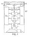
- FIG. 3shows a block diagram illustrating electrical aspects of a speaker unit in accordance with one embodiment of the invention.
- FIG. 4shows a block diagram illustrating electrical aspects of an expander power converter in accordance with one embodiment of the invention.
- an audio distribution system 10in one embodiment includes a master mixer/power converter 20 which includes a series of audio inputs 21 for receiving audio signals from a microphone 30 and/or other audio sources 40 .
- the audio sources 40may include sources of music content such as, e.g., a satellite radio receiver, a CD player, a radio tuner, an internet radio receiver, a digital audio player, or the like.
- the audio inputs 21may be analog inputs, digital inputs, or a combination thereof.
- the audio sourcesmay be separate from the master mixer/power converter 20 , as shown in FIG. 1 , or may be integrated therewith.
- the master mixer/power converter 20includes a digital power link out port 33 ( FIG. 2 ) for outputting digital audio and power over a network cable 50 , which may comprise, e.g., CAT5 or CAT5E cable or other similar twisted-pair network cabling terminated at each end with an RJ-45 connection.
- a network cable 50may comprise, e.g., CAT5 or CAT5E cable or other similar twisted-pair network cabling terminated at each end with an RJ-45 connection.
- This cable and termination connectionsTransmitting audio data in digital form across such twisted-pair cable provides resistance to radio-frequency interference over conventional speaker cables, and its RJ-45 connectors can be used to quickly connect the various components of the present system without the risk of improper wiring.
- common networking cable with RJ-45 or similar terminationsreduces the chance of connection failure and/or inadvertent disconnection and facilitates making connections between various components of the system by consolidating wiring into a single connector.
- One or more of the four twisted pairs of conductors within the network cable 50may be used to carry the digital audio signal, and one or more of the remaining pairs may be used to carry power.
- the digital power link out portis discussed in further detail below with reference to FIG. 2 .
- each speaker unitcomprises a DSP, a digital-to-analog converter, an audio power amplifier, a ceiling-mounted speaker, and suitable digital power link in and out jacks.
- a suitable digital power link in and out jackis an RJ45 female jack, however, any suitable jack may be used.
- the network cable 50connects the digital power link out jack on the master mixer/power converter 20 to a digital power link in jack in speaker unit SU 1 .
- a second network cablemay connect the digital power link out jack in speaker unit SU 1 to a digital power link in jack in speaker unit SU 2 .
- a third network cablemay be used to connect the digital power link out jack in speaker unit SU 2 to a digital power link in jack in speaker unit SU 3 , and so on until a maximum number of speaker units has been reached.
- a maximum number of speakersmay occur as a result of a number of factors, for example, but not by way of limitation, the amount of power consumed by the daisy-chained speakers may not provide enough power to operate another speaker.
- Another example, also intended to illustrate and not to limit the inventionis that the length of cable between the speaker units is sufficiently large that the power or audio signal remaining is too weak to travel further.
- each expander power converter EX 1 , EX 2also includes digital power link in and out jacks.
- the digital power link in jack in the expander power converter EX 1connects via cable to the digital power link out jack in the last speaker unit in the chain, SUn, and the digital power link out jack in the expander power converter EX 1 connects via cable to the digital power link in jack of the next speaker unit SU 9 in the chain.
- This daisy chainingis continued until a maximum number of speaker units has again been reached, at which point a second expander power converter EX 2 is connected at the end of the chain to allow further speaker units to be added.
- the master mixer/power converter 20may include one or more link out ports which output digital audio but do not provide power.
- the link out portmay be connected via a network cable 52 to a remote expander power converter EX 3 , which outputs both digital audio and power to a further chain of speakers.
- FIG. 2shows a block diagram illustrating selected electrical aspects and functionality of the master mixer/power converter 20 .
- a digital audio receiver 21 and a digital audio transmitter 23are provided for respectively receiving digital audio inputs and transmitting digital audio outputs.
- the digital audio receiver 21 and digital audio transmitter 23receive and transmit two channels of digital audio, shown in the figures as two lines, and designated herein as a speech channel and a music channel.
- the digital audio receiver 21 and digital audio transmitter 23may receive and transmit, using AES/EBU digital audio inputs and outputs as is know in the art.
- Analog audio inputs 29are provided for receiving analog audio from sources such as a microphone and line level analog audio sources.
- analog audio inputs 29 aare designated as part of a speech channel
- analog audio inputs 29 bare designated part of a music channel.
- the music channelmay have any combination of inputs, and need not have any music at all.
- the speech channel and music channelmay be handled differently within, or outside the master mixer/power converter 20 , and it is thus it may be beneficial to provide the two channels.
- a remote volume control inputmay be provided for remotely controlling volume levels output by the speaker units.
- one or more link in inputs 31may be provided for connecting the master mixer/power converter 20 to other system components, including additional master mixer/power converters, in a daisy-chain manner to add functionality and/or provide additional inputs.
- One or more link in input ports 31may also be provided for receiving audio input from digital sources rather than from other master mixer/power converters.
- An analog-to-digital converter 37converts the analog signals from analog inputs 29 to digital format.
- the conversionprovides at least two channels of digital audio output—a first channel, designed a “speech channel”, may be used for speech from sources such as microphone 30 ( FIG. 1 ), and a second channel, designated a “music channel”, may be used for music or other audio content, from other audio sources 40 ( FIG. 1 ).
- these channelsare not limited to a specific type of content.
- a digital signal processor 27receives the digital audio, including the speech channel and the music channel, from the analog-to-digital converter 37 .
- the digital signal processor 27may also receive two or more digital audio channels from the digital audio receiver 21 .
- the digital audio receiver 21provides a speech channel and a music channel to the DSP 27 .
- the digital signal processor 27applies digital processing, such as equalization and compression, to the digital audio signal.
- the digital signal processor 27in one embodiment provides at least two channel processing.
- the speech channel of the digital audio signalis processed in accordance with equalization and/or compression algorithms which are selected to improve the intelligibility of the content transmitted on the speech channel.
- the digital signal processormay, when processing the speech channel, cause frequencies in the speech-typical mid band to be emphasized, and may cause frequencies in the low band, and/or frequencies outside of those associated with the human voice, to be attenuated.
- the digital signal processormay, when processing the speech channel, apply a relatively high level of compression to the speech channel to reduce the bandwidth used by the channel.
- the digital signal processorallows the speech channel to be adjusted in volume level independently of the music channel.
- the digital signal processor 27may apply to the music channel different equalization and/or compression algorithms which are appropriate for non-speech audio such as commercial music. For example, without intending to limit the scope of the invention, low frequency response may be enhanced in the music channel to provide improved bass response.
- no equalization or compressionis applied to the music channel, while the speech channel is processed to improve intelligibility of voice content.
- no equalization or compressionis applied to the speech channel, while the music channel is processed to enhance music content.
- the music channelis slightly or significantly attenuated when the speech channel is in use.
- the output of the digital signal processor 27is received by a digital audio transmitter 23 , which formats the digital audio signal for output over a network cable via a digital power link out port 33 and/or a link out port 35 .
- the digital power link out port 33 and the link out port 35supply such digital audio signal to one or more pairs of twisted conductors in an ethernet cable or other network cable appropriate for transmission of digital signals.
- the digital power link out port 33 and the link out portmay comprise, e.g., RJ-45 female connectors.
- the digital power link out port 33supplies electrical power from the regulated power supply 25 over the connected network cable.
- the poweris conducted from the regulated power supply to the digital power link out port 33 to which the network cable is connected.
- the powermay be, e.g., at 48V DC, or other voltage appropriate to drive an audio power amplifier at the speaker unit(s) connected in the daisy chain manner as described above.
- the regulated power supply 25receives A/C power from an A/C in jack or plug, and sends DC power to pins of the digital power link out jack 33 . While the power to the digital power link out jack 33 could be AC power, using AC power may cause interference that may prevents the digital audio signal from being transmitted in the same cable.
- poweris supplied to two or more pins of the digital power link out jack 33 .
- poweris supplied to four pins of the digital power link out jack 33 , the speech channel is transmitted on two pins of the digital power link out jack 33 and the music channel is transmitted on two pins of the digital power link out jack 33 .
- poweris supplied to six pins of the digital power link out jack 33 , and the speech and music channel are multiplexed on two pins of the digital power link out jack 33 .
- the pairs of conductors carrying the power signalmay all carry power at the same voltage, or may carry power at different voltages. Thus, for example, power may be supplied over the network cable to the audio power amplifier of the speaker units at a relatively high voltage sufficient to drive the amplifier, and may be supplied over a separate pair to the DSP of the speaker units at another, lower voltage.
- the regulated power supplyfurther provides power to the various components and circuits of the master mixer/power converter 20 , e.g., the digital audio receiver 21 , the analog-to-digital converter 37 , the DSP 27 , and the digital audio transmitter 23 .
- one or more of the pairs of conductorsmay be used to transmit control signals and/or data signals other than digital audio to the speaker units.
- such pair or pairsmay be used to transmit one or more of the following: volume control signals, equalization or signal processing settings, digital video, data from a computer's network interface card, or other signals.
- multiple digital power link out portsare provided to support further chains of speaker units, and each such chain may transmit content which is the same as or different than that of the digital power link out port 25 .
- FIG. 3shows a block diagram illustrating electrical aspects of a speaker unit SU in accordance with one embodiment of the invention.
- a digital power link in port 59which may comprise, e.g., an RJ-45 jack, receives digital audio and power signals from a preceding component in the chain.
- Such preceding componentmay be, e.g., the master mixer/power converter 20 ( FIGS. 1 and 2 ), another speaker unit, or an expander/power converter EX 1 , EX 2 or EX 3 ( FIG. 1 ).
- the digital audio and power signals received at the digital power link in port 59are both passed to the digital power link out port.
- either of the digital power link portscan be used for the input of the cable carrying power and audio, and the other can be used as the output to daisy-chain the power and audio signal to additional speaker units.
- the two portsmay be interchangeable. This simplifies the installation of the system, and greatly reduces the possibility that the speaker units will be mis-wired when installed.
- the power signal received at the digital power link in port 59is also provided to the power circuits 63 for powering the internal electrical components of the speaker unit.
- a digital audio receiver 61receives the digital audio signal from the digital power link in port 59 and provides a digital audio signal to a digital signal processor 53 .
- the digital audio signalin one embodiment includes both the speech channel and the music channel.
- the digital signal processor 53performs a digital sum of the speech channel and the music channel, and then a digital crossover function on the summed speech channel and music channel splitting it into high frequency and low frequency components.
- the digital audio signal which is output from the digital signal processor 53contains two audio channels.
- This digital audio signalmay be in pulse-code-modulated (PCM) form, or other digital audio format.
- PCMpulse-code-modulated
- the digital signal processor 53may perform equalization on the speech channel and/or on the music channel prior to summing the channels.
- the equalizationmay be configured for the speaker individually, and may be configured to accommodate acoustics or ambient noise local to the speaker. This type of flexibility permits a speaker situated above a marble floor, for example, to be equalized differently, on a per channel basis, than a speaker situated above a carpet or other acoustically absorptive surface.
- a Pulse-Width-Modulation (PWM) controller 51receives the two channels of digital audio from the digital signal processor 53 and converts each channel to a PWM signal comprising a train of pulses whose width varies in accordance with frequency of the encoded audio. Two PWM signals are thus output from the PWM controller 51 . As shown in FIG. 3 , these are designated PWM-LF (low frequencies) and PWM-HF (high frequencies). The PWM signals are used to drive a Class D digital power amplifier 57 .
- the Class D digital power amplifier 57utilizes the PWM signals to switch an output power amplifier device on and off to provide an amplified analog signal.
- the output power amplifier devicemay be, e.g., a power MOSFET.
- the Class D digital power amplifier 57is a multi-channel amplifier operating at 20 watts per channel or more.
- the digital power amplifiermay be set up for bi-amplification of the speech channel and the music channel. That is, the high-frequency components of those channels may be amplified separately from the low-frequency components.
- Each of the two separately amplified analog signalsmay be used to drive one or more speaker drivers 65 , 65 a .
- the low frequency signalis used to drive a speaker driver 65 , for example, but not by way of limitation, a 6.5′′ woofer with 20 oz. magnet
- the high frequency signalis used to drive a speaker driver 65 a , for example, but not by way of limitation, a 1′′ horn-loaded silk dome tweeter.
- the speaker unit as shown in FIG. 3may be provided in a single speaker enclosure or other unit.
- the speaker unitis a ceiling mounted speaker, and the speaker drivers 65 , 65 a are downward-facing.
- the speaker unitmay be a wall-mounted speaker that is either recessed into a wall or surface-mounted to the wall, or even a free-standing speaker such as a floor-standing speaker or bookshelf type speaker.
- speaker drivers 65 , 65 aare shown separated, as will be apparent to one of skill in the art, the smaller speaker driver 65 a may be situated within the perimeter of larger speaker driver 65 .
- the digital signal processor 53 and PWM controller 51output out a single signal comprising both the high and low frequency components, rather than outputting two separate signals.
- Amplifier 57may thus amplify only the single signal, and outputs a single signal to a single full-range speaker (not shown.)
- the equalization of the speech and music channelscan be achieved prior to the combination of the two into a single signal.
- the speaker unit as described abovecan be used advantageously in audio systems other than the audio distribution system described hereinabove.
- the speaker unitcan be used in conjunction with a digital output of any audio source to provide a powered speaker which avoids signal loss, particularly where long cable runs are employed between the audio source and the speaker unit.
- the use of highly efficient class D amplificationprovides a powered speaker with very low power consumption which can be powered via cabling which is also used to transmit digital audio to the speaker.
- FIG. 4shows a block diagram illustrating various electrical aspects of the expander/power converter EX 1 which is used to expand a daisy chain of speakers once the maximum number of speakers in the chain has been reached.
- the expander/power converter as shownmay also be used to add remote speakers or daisy chains of speakers, as shown at element EX 3 in FIG. 1 , or may be used as an alternative to the master mixer/power converter where only a limited number of analog inputs and processing are required.
- a digital audio receiver 121 and a digital audio transmitter 123are provided for respectively receiving digital audio inputs and transmitting digital audio outputs, such as AES/EBU digital audio inputs and outputs.
- Analog audio inputs 129which may be, e.g., a mini stereo 1 ⁇ 8′′ TRS jack or a pair of RCA jacks, are provided for receiving analog audio from sources such as such as a DVD player, CD player, or the like.
- a link in input 131may be provided for connecting the expander/power converter EX 1 to the last speaker unit in the chain SUn ( FIG. 1 ) or other upstream system components such as the master mixer/power converter.
- an analog-to-digital converter 137may be provided to convert the analog signals from analog inputs 129 to digital format.
- a digital signal processor 127receives the digital audio from the analog-to-digital converter 137 , and receives digital audio from the digital audio receiver 121 .
- the digital signal processor 127may apply digital processing, such as equalization and compression, to the digital audio signal in a manner similar to that described above with reference to the functions of the DSP in the master mixer/power converter 20 ( FIG. 1 ).
- the analog inputs 129may be treated as a speech channel or as a music channel by the digital signal processor 127 . Note that an EX 1 need not include analog inputs 129 , nor ADC 137 .
- the output of the digital signal processor 127is received by a digital audio transmitter 23 , which formats the digital audio signal for output over a network cable via a digital power link out port 133 and/or a link out port 135 .
- the digital power link out port 133 and the link out port 135supply such digital audio signal to one or more pairs of twisted conductors in an ethernet cable or other network cable appropriate for transmission of digital signals.
- the digital power link out port 133 and the link out portmay comprise, e.g., RJ-45 female connectors.
- the digital power link out port 133supplies electrical power from the regulated power supply 125 over the connected network cable in much the same manner as is described above in connection with the digital power link out port 133 of the master mixer/power supply.
- the regulated power supply 125receives AC power from an A/C in jack or plug, and sends DC power to six pins of the digital power link out jack 133 .
- This DC power signalis used to power further speaker units SU 9 through SUn′ ( FIG. 1 ) downstream from the expander/power converter EX 1 .
Landscapes
- Engineering & Computer Science (AREA)
- Signal Processing (AREA)
- Physics & Mathematics (AREA)
- Acoustics & Sound (AREA)
- Power Engineering (AREA)
- Computer Networks & Wireless Communication (AREA)
- Circuit For Audible Band Transducer (AREA)
- Amplifiers (AREA)
Abstract
Description
Claims (15)
Priority Applications (1)
| Application Number | Priority Date | Filing Date | Title |
|---|---|---|---|
| US11/373,505US8385561B2 (en) | 2006-03-13 | 2006-03-13 | Digital power link audio distribution system and components thereof |
Applications Claiming Priority (1)
| Application Number | Priority Date | Filing Date | Title |
|---|---|---|---|
| US11/373,505US8385561B2 (en) | 2006-03-13 | 2006-03-13 | Digital power link audio distribution system and components thereof |
Publications (2)
| Publication Number | Publication Date |
|---|---|
| US20070223722A1 US20070223722A1 (en) | 2007-09-27 |
| US8385561B2true US8385561B2 (en) | 2013-02-26 |
Family
ID=38533458
Family Applications (1)
| Application Number | Title | Priority Date | Filing Date |
|---|---|---|---|
| US11/373,505Active2030-10-14US8385561B2 (en) | 2006-03-13 | 2006-03-13 | Digital power link audio distribution system and components thereof |
Country Status (1)
| Country | Link |
|---|---|
| US (1) | US8385561B2 (en) |
Cited By (6)
| Publication number | Priority date | Publication date | Assignee | Title |
|---|---|---|---|---|
| US20100084199A1 (en)* | 2007-06-07 | 2010-04-08 | Mettler-Toledo Ag | Multiple force-measuring device, force-measuring module, and method for monitoring a condition of the multiple force-measuring device |
| US9794679B2 (en) | 2014-02-14 | 2017-10-17 | Sonic Blocks, Inc. | Modular quick-connect A/V system and methods thereof |
| WO2018005895A1 (en)* | 2016-06-29 | 2018-01-04 | Oneview Controls, Inc. | Common distribution of audio and power signals |
| US9883046B1 (en)* | 2016-11-17 | 2018-01-30 | Crestron Electronics, Inc. | Retrofit digital network speaker system |
| US10321232B2 (en) | 2015-04-02 | 2019-06-11 | Dolby Laboratories Licensing Corporation | Distributed amplification for adaptive audio rendering systems |
| US11665492B2 (en)* | 2018-10-03 | 2023-05-30 | Crestron Electronics, Inc. | In-ceiling loudspeaker assembly with digital interface |
Families Citing this family (18)
| Publication number | Priority date | Publication date | Assignee | Title |
|---|---|---|---|---|
| US20060115101A1 (en)* | 2004-11-18 | 2006-06-01 | Schoenberger Michael A | Multiple amplifier synchronization system |
| KR101341698B1 (en) | 2006-05-21 | 2013-12-16 | 트라이젠스 세미컨덕터 가부시키가이샤 | Digital/analogue conversion apparatus |
| US20080002843A1 (en)* | 2006-07-03 | 2008-01-03 | Tsung-Ming Cheng | Ripple digital amplifier system |
| SE531023C2 (en)* | 2007-02-08 | 2008-11-18 | Paer Gunnars Risberg | Listening System |
| JP5552620B2 (en) | 2008-06-16 | 2014-07-16 | 株式会社 Trigence Semiconductor | A car equipped with a digital speaker driving device and a centralized control device |
| US8131386B2 (en)* | 2009-06-15 | 2012-03-06 | Elbex Video Ltd. | Method and apparatus for simplified interconnection and control of audio components of an home automation system |
| US8571237B2 (en)* | 2009-07-02 | 2013-10-29 | Amp'd PC Technologies, LLC | Multi-zone audio amplification system for multimedia |
| EP2391014B1 (en) | 2009-12-09 | 2017-12-27 | Trigence Semiconductor, Inc. | Selection device |
| KR20120101186A (en)* | 2009-12-16 | 2012-09-13 | 트라이젠스 세미컨덕터 가부시키가이샤 | Acoustic playback system |
| US9510116B2 (en)* | 2010-06-08 | 2016-11-29 | Isp Technologies, Llc | High definition distributed sound system |
| ES2851229T3 (en) | 2011-10-07 | 2021-09-03 | Audinate Holdings Pty Ltd | Systems, methods and devices for interconnection of networks over high impedance cabling |
| EP2834815A4 (en)* | 2012-04-05 | 2015-10-28 | Nokia Technologies Oy | Adaptive audio signal filtering |
| US20160050492A1 (en)* | 2013-02-26 | 2016-02-18 | The University Of Akron | Direct-drive digital audio amplifier for electrostatic loudspeakers |
| DE202014010303U1 (en)* | 2014-07-01 | 2015-04-08 | Thomas Gessler | Programmable, digital sound reproduction network |
| DE102017006678A1 (en)* | 2017-07-14 | 2019-01-17 | Drägerwerk AG & Co. KGaA | Cascadable multi-loader and method of operation thereof |
| US11599329B2 (en)* | 2018-10-30 | 2023-03-07 | Sony Corporation | Capacitive environmental sensing for a unique portable speaker listening experience |
| US10652664B1 (en)* | 2019-06-28 | 2020-05-12 | Bose Corporation | Active loudspeaker and cable assembly |
| US20230269533A1 (en)* | 2021-02-22 | 2023-08-24 | Shure Acquisition Holdings, Inc. | Multi-Channel Microphone |
Citations (16)
| Publication number | Priority date | Publication date | Assignee | Title |
|---|---|---|---|---|
| US5341374A (en) | 1991-03-01 | 1994-08-23 | Trilan Systems Corporation | Communication network integrating voice data and video with distributed call processing |
| US5537141A (en) | 1994-04-15 | 1996-07-16 | Actv, Inc. | Distance learning system providing individual television participation, audio responses and memory for every student |
| US5838393A (en)* | 1996-04-12 | 1998-11-17 | Stargrabber Llc | Audio/video/control remote switching device |
| US6072879A (en)* | 1996-06-17 | 2000-06-06 | Yamaha Corporation | Sound field control unit and sound field control device |
| US6130898A (en) | 1995-03-16 | 2000-10-10 | Bell Atlantic Network Services, Inc. | Simulcasting digital video programs for broadcast and interactive services |
| US20020154783A1 (en) | 2001-02-09 | 2002-10-24 | Lucasfilm Ltd. | Sound system and method of sound reproduction |
| US20020166125A1 (en) | 2001-03-05 | 2002-11-07 | Fulmer Daniel E. | Universal home cabling system |
| US6686530B2 (en) | 1999-04-26 | 2004-02-03 | Gibson Guitar Corp. | Universal digital media communications and control system and method |
| US20040220687A1 (en) | 2001-07-20 | 2004-11-04 | Thomas Klotz | Device and method for transmitting, receiving and processing audio control signals in information systems |
| US20040225388A1 (en) | 2001-07-17 | 2004-11-11 | Guohua Zhang | Fully digitized audio system |
| US20040223622A1 (en)* | 1999-12-01 | 2004-11-11 | Lindemann Eric Lee | Digital wireless loudspeaker system |
| US20050027888A1 (en) | 2002-07-10 | 2005-02-03 | Juszkiewicz Henry E. | Universal digital communications and control system for consumer electronic devices |
| WO2005022804A2 (en) | 2003-08-30 | 2005-03-10 | Klotz Digital Ag | Method and system for efficiently transmitting power when acoustically irradiating rooms |
| EP1517464A2 (en)* | 2003-09-03 | 2005-03-23 | Phoenix Gold International, Inc. | Digital audio distribution system |
| US20050131558A1 (en) | 2002-05-09 | 2005-06-16 | Michael Braithwaite | Audio network distribution system |
| US6931134B1 (en) | 1998-07-28 | 2005-08-16 | James K. Waller, Jr. | Multi-dimensional processor and multi-dimensional audio processor system |
- 2006
- 2006-03-13USUS11/373,505patent/US8385561B2/enactiveActive
Patent Citations (16)
| Publication number | Priority date | Publication date | Assignee | Title |
|---|---|---|---|---|
| US5341374A (en) | 1991-03-01 | 1994-08-23 | Trilan Systems Corporation | Communication network integrating voice data and video with distributed call processing |
| US5537141A (en) | 1994-04-15 | 1996-07-16 | Actv, Inc. | Distance learning system providing individual television participation, audio responses and memory for every student |
| US6130898A (en) | 1995-03-16 | 2000-10-10 | Bell Atlantic Network Services, Inc. | Simulcasting digital video programs for broadcast and interactive services |
| US5838393A (en)* | 1996-04-12 | 1998-11-17 | Stargrabber Llc | Audio/video/control remote switching device |
| US6072879A (en)* | 1996-06-17 | 2000-06-06 | Yamaha Corporation | Sound field control unit and sound field control device |
| US6931134B1 (en) | 1998-07-28 | 2005-08-16 | James K. Waller, Jr. | Multi-dimensional processor and multi-dimensional audio processor system |
| US6686530B2 (en) | 1999-04-26 | 2004-02-03 | Gibson Guitar Corp. | Universal digital media communications and control system and method |
| US20040223622A1 (en)* | 1999-12-01 | 2004-11-11 | Lindemann Eric Lee | Digital wireless loudspeaker system |
| US20020154783A1 (en) | 2001-02-09 | 2002-10-24 | Lucasfilm Ltd. | Sound system and method of sound reproduction |
| US20020166125A1 (en) | 2001-03-05 | 2002-11-07 | Fulmer Daniel E. | Universal home cabling system |
| US20040225388A1 (en) | 2001-07-17 | 2004-11-11 | Guohua Zhang | Fully digitized audio system |
| US20040220687A1 (en) | 2001-07-20 | 2004-11-04 | Thomas Klotz | Device and method for transmitting, receiving and processing audio control signals in information systems |
| US20050131558A1 (en) | 2002-05-09 | 2005-06-16 | Michael Braithwaite | Audio network distribution system |
| US20050027888A1 (en) | 2002-07-10 | 2005-02-03 | Juszkiewicz Henry E. | Universal digital communications and control system for consumer electronic devices |
| WO2005022804A2 (en) | 2003-08-30 | 2005-03-10 | Klotz Digital Ag | Method and system for efficiently transmitting power when acoustically irradiating rooms |
| EP1517464A2 (en)* | 2003-09-03 | 2005-03-23 | Phoenix Gold International, Inc. | Digital audio distribution system |
Non-Patent Citations (4)
| Title |
|---|
| "IEEE802.3af Power Over Ethernet: A Radical New Technology," http://www.poweroverethernet.com/articles.php?article-id=52 ; pp. 1-10, 2003. |
| "Power Over Ethernet News," printout from website; http://www.poweroverethernet.com/, Mar. 13, 2006, pp. 1-3. |
| "Standards Project: IEEE 802.3 DTE Power via MDI Study Group," title, Proposed DC Power Requirements for Power via MDI, Sep. 31, 1999, pp. 1-9. |
| "What is Power-over-Ethernet (PoE)?," printout from website, http://www.hyperlinktech.com/web/what-is-poe.php ; Mar. 13, 2006, pp. 1-3. |
Cited By (15)
| Publication number | Priority date | Publication date | Assignee | Title |
|---|---|---|---|---|
| US8648266B2 (en)* | 2007-06-07 | 2014-02-11 | Mettler-Toledo Ag | Multiple force-measuring device, force-measuring module, and method for monitoring a condition of the multiple force-measuring device |
| US20100084199A1 (en)* | 2007-06-07 | 2010-04-08 | Mettler-Toledo Ag | Multiple force-measuring device, force-measuring module, and method for monitoring a condition of the multiple force-measuring device |
| US11381903B2 (en) | 2014-02-14 | 2022-07-05 | Sonic Blocks Inc. | Modular quick-connect A/V system and methods thereof |
| US9794679B2 (en) | 2014-02-14 | 2017-10-17 | Sonic Blocks, Inc. | Modular quick-connect A/V system and methods thereof |
| US12225344B2 (en) | 2014-02-14 | 2025-02-11 | Sonic Blocks, Inc. | Modular quick-connect A/V system and methods thereof |
| US10034079B2 (en) | 2014-02-14 | 2018-07-24 | Sonic Blocks, Inc. | Modular quick-connect A/V system and methods thereof |
| US10321232B2 (en) | 2015-04-02 | 2019-06-11 | Dolby Laboratories Licensing Corporation | Distributed amplification for adaptive audio rendering systems |
| WO2018005895A1 (en)* | 2016-06-29 | 2018-01-04 | Oneview Controls, Inc. | Common distribution of audio and power signals |
| US10771528B2 (en)* | 2016-06-29 | 2020-09-08 | Oneview Controls, Inc. | Common distribution of audio and power signals |
| US20190319999A1 (en)* | 2016-06-29 | 2019-10-17 | Oneview Controls, Inc. | Common distribution of audio and power signals |
| US11399051B2 (en)* | 2016-06-29 | 2022-07-26 | Oneview Controls, Inc. | Common distribution of audio and power signals |
| US10491751B2 (en)* | 2016-11-17 | 2019-11-26 | Crestron Electronics, Inc. | Retrofit digital network speaker system |
| US10686943B2 (en) | 2016-11-17 | 2020-06-16 | Crestron Electronics, Inc. | Retrofit digital network speaker system |
| US9883046B1 (en)* | 2016-11-17 | 2018-01-30 | Crestron Electronics, Inc. | Retrofit digital network speaker system |
| US11665492B2 (en)* | 2018-10-03 | 2023-05-30 | Crestron Electronics, Inc. | In-ceiling loudspeaker assembly with digital interface |
Also Published As
| Publication number | Publication date |
|---|---|
| US20070223722A1 (en) | 2007-09-27 |
Similar Documents
| Publication | Publication Date | Title |
|---|---|---|
| US8385561B2 (en) | Digital power link audio distribution system and components thereof | |
| US8175289B2 (en) | Digital audio distribution network | |
| US8320824B2 (en) | Methods and systems to provide automatic configuration of wireless speakers | |
| US20080188965A1 (en) | Remote audio device network system and method | |
| US20060235552A1 (en) | Method and system for media content data distribution and consumption | |
| US20170070195A1 (en) | Method for controlling power consumption of a loudspeaker system | |
| US7440750B2 (en) | Signal routing for reduced power consumption in a conferencing system | |
| JP2001516197A (en) | Distributed stereo audio system | |
| MXPA01010077A (en) | Remote control having an audio port. | |
| AU2017268383B2 (en) | Self-powered loudspeaker for sound masking | |
| US20140119561A1 (en) | Methods and systems to provide automatic configuration of wireless speakers | |
| KR101106681B1 (en) | Two-way digital conversion audio transmission system | |
| US20240053948A1 (en) | Hybrid input networked audio subwoofer | |
| KR101057670B1 (en) | Sound network transmission system | |
| US20040162025A1 (en) | Enhanced embedded electronics for wireless transmission and reception of audio in subwoofer applications | |
| CN207766527U (en) | Audio conversion equipment and multi-sound system | |
| US11317208B2 (en) | Speaker system and speaker configuration method | |
| US20090092266A1 (en) | Wireless audio system capable of receiving commands or voice input | |
| KR20080025769A (en) | PLC speaker system | |
| JP2003264893A (en) | Audio signal transmission device | |
| GB2378874A (en) | Audiovisual distribution system | |
| Dawson | Sonab sound and society system 9 speaker system | |
| Learning | Product overview | |
| US20080229378A1 (en) | System and Method of Distributing Audio and Video Signals | |
| JP2000312399A (en) | Remote control desk system |
Legal Events
| Date | Code | Title | Description |
|---|---|---|---|
| AS | Assignment | Owner name:ALTEC LANSING TECHNOLOGIES, INC., PENNSYLVANIA Free format text:ASSIGNMENT OF ASSIGNORS INTEREST;ASSIGNORS:MERREY, F. DAVIS;JONES, GARY;REEL/FRAME:017494/0090 Effective date:20060417 | |
| AS | Assignment | Owner name:PLANTRONICS, INC., CALIFORNIA Free format text:MERGER;ASSIGNOR:ALTEC LANSING TECHNOLOGIES, INC.;REEL/FRAME:021852/0184 Effective date:20061030 Owner name:PLANTRONICS, INC.,CALIFORNIA Free format text:MERGER;ASSIGNOR:ALTEC LANSING TECHNOLOGIES, INC.;REEL/FRAME:021852/0184 Effective date:20061030 | |
| AS | Assignment | Owner name:PNC BANK, NATIONAL ASSOCIATION, TEXAS Free format text:SECURITY AGREEMENT;ASSIGNOR:ALTEC LANSING, LLC;REEL/FRAME:023821/0028 Effective date:20091201 Owner name:PNC BANK, NATIONAL ASSOCIATION,TEXAS Free format text:SECURITY AGREEMENT;ASSIGNOR:ALTEC LANSING, LLC;REEL/FRAME:023821/0028 Effective date:20091201 | |
| AS | Assignment | Owner name:ALTEC LANSING, LLC, PENNSYLVANIA Free format text:ASSIGNMENT OF ASSIGNORS INTEREST;ASSIGNOR:PLANTRONICS, INC.;REEL/FRAME:023832/0843 Effective date:20091201 Owner name:ALTEC LANSING, LLC,PENNSYLVANIA Free format text:ASSIGNMENT OF ASSIGNORS INTEREST;ASSIGNOR:PLANTRONICS, INC.;REEL/FRAME:023832/0843 Effective date:20091201 | |
| STCF | Information on status: patent grant | Free format text:PATENTED CASE | |
| AS | Assignment | Owner name:TYMPHANY HONG KONG LIMITED, CALIFORNIA Free format text:ASSIGNMENT OF ASSIGNORS INTEREST;ASSIGNOR:AL SHELLCO LLC (F/K/A ALTEC LANSING, LLC;REEL/FRAME:035456/0062 Effective date:20130131 | |
| AS | Assignment | Owner name:D&M HOLDINGS, INC., JAPAN Free format text:ASSIGNMENT OF ASSIGNORS INTEREST;ASSIGNOR:TYMPHANY HONG KONG LIMITED;REEL/FRAME:036444/0715 Effective date:20150827 | |
| FPAY | Fee payment | Year of fee payment:4 | |
| AS | Assignment | Owner name:SOUND UNITED, LLC, CALIFORNIA Free format text:GRANT OF SECURITY INTEREST;ASSIGNOR:D&M HOLDINGS INC.;REEL/FRAME:042622/0011 Effective date:20170526 | |
| FEPP | Fee payment procedure | Free format text:ENTITY STATUS SET TO UNDISCOUNTED (ORIGINAL EVENT CODE: BIG.); ENTITY STATUS OF PATENT OWNER: LARGE ENTITY | |
| MAFP | Maintenance fee payment | Free format text:PAYMENT OF MAINTENANCE FEE, 8TH YEAR, LARGE ENTITY (ORIGINAL EVENT CODE: M1552); ENTITY STATUS OF PATENT OWNER: LARGE ENTITY Year of fee payment:8 | |
| AS | Assignment | Owner name:CERBERUS BUSINESS FINANCE, LLC, AS THE COLLATERAL AGENT, NEW YORK Free format text:NOTICE OF SECURITY INTEREST - PATENTS;ASSIGNORS:DEI SALES, INC.;D&M HOLDINGS U.S. INC.;BOSTON ACOUSTICS, INC.;AND OTHERS;REEL/FRAME:054300/0611 Effective date:20201009 | |
| AS | Assignment | Owner name:D&M HOLDINGS INC, JAPAN Free format text:RELEASE OF SECURITY INTEREST IN PATENTS;ASSIGNOR:SOUND UNITED, LLC;REEL/FRAME:054858/0361 Effective date:20201224 | |
| AS | Assignment | Owner name:CERBERUS BUSINESS FINANCE, LLC, AS COLLATERAL AGENT, NEW YORK Free format text:NOTICE OF SECURITY INTEREST - - PATENTS;ASSIGNOR:D&M HOLDINGS INC.;REEL/FRAME:054874/0184 Effective date:20201228 | |
| AS | Assignment | Owner name:BANK OF AMERICA, N.A., AS COLLATERAL AGENT, NORTH CAROLINA Free format text:ABL PATENT SECURITY AGREEMENT;ASSIGNORS:BOSTON ACOUSTICS, INC.;DEI SALES, INC.;DEI HOLDINGS, INC.;AND OTHERS;REEL/FRAME:056193/0207 Effective date:20210429 Owner name:BANK OF AMERICA, N.A., AS COLLATERAL AGENT, NORTH CAROLINA Free format text:FIRST LIEN PATENT SECURITY AGREEMENT;ASSIGNORS:BOSTON ACOUSTICS, INC.;DEI SALES, INC.;DEI HOLDINGS, INC.;AND OTHERS;REEL/FRAME:056193/0230 Effective date:20210429 | |
| AS | Assignment | Owner name:D&M HOLDINGS INC., CALIFORNIA Free format text:RELEASE OF SECURITY INTEREST IN INTELLECTUAL PROPERTY;ASSIGNOR:CERBERUS BUSINESS FINANCE, LLC, AS AGENT;REEL/FRAME:059127/0278 Effective date:20210429 Owner name:B & W LOUDSPEAKERS LTD, UNITED KINGDOM Free format text:RELEASE OF SECURITY INTEREST IN INTELLECTUAL PROPERTY;ASSIGNOR:CERBERUS BUSINESS FINANCE, LLC, AS AGENT;REEL/FRAME:059127/0278 Effective date:20210429 Owner name:SOUND UNITED, LLC, CALIFORNIA Free format text:RELEASE OF SECURITY INTEREST IN INTELLECTUAL PROPERTY;ASSIGNOR:CERBERUS BUSINESS FINANCE, LLC, AS AGENT;REEL/FRAME:059127/0278 Effective date:20210429 Owner name:B & W GROUP LTD, UNITED KINGDOM Free format text:RELEASE OF SECURITY INTEREST IN INTELLECTUAL PROPERTY;ASSIGNOR:CERBERUS BUSINESS FINANCE, LLC, AS AGENT;REEL/FRAME:059127/0278 Effective date:20210429 Owner name:D&M EUROPE B.V., CALIFORNIA Free format text:RELEASE OF SECURITY INTEREST IN INTELLECTUAL PROPERTY;ASSIGNOR:CERBERUS BUSINESS FINANCE, LLC, AS AGENT;REEL/FRAME:059127/0278 Effective date:20210429 Owner name:BOSTON ACOUSTICS, INC., CALIFORNIA Free format text:RELEASE OF SECURITY INTEREST IN INTELLECTUAL PROPERTY;ASSIGNOR:CERBERUS BUSINESS FINANCE, LLC, AS AGENT;REEL/FRAME:059127/0278 Effective date:20210429 Owner name:DEFINITIVE TECHNOLOGY, LLC, CALIFORNIA Free format text:RELEASE OF SECURITY INTEREST IN INTELLECTUAL PROPERTY;ASSIGNOR:CERBERUS BUSINESS FINANCE, LLC, AS AGENT;REEL/FRAME:059127/0278 Effective date:20210429 Owner name:DIRECTED, LLC, CALIFORNIA Free format text:RELEASE OF SECURITY INTEREST IN INTELLECTUAL PROPERTY;ASSIGNOR:CERBERUS BUSINESS FINANCE, LLC, AS AGENT;REEL/FRAME:059127/0278 Effective date:20210429 Owner name:POLK AUDIO, LLC, CALIFORNIA Free format text:RELEASE OF SECURITY INTEREST IN INTELLECTUAL PROPERTY;ASSIGNOR:CERBERUS BUSINESS FINANCE, LLC, AS AGENT;REEL/FRAME:059127/0278 Effective date:20210429 | |
| AS | Assignment | Owner name:EQUITY INTERNATIONAL LLC, MASSACHUSETTS Free format text:RELEASE OF SECURITY INTEREST IN PATENT COLLATERAL (REEL/FRAME 056193/0207);ASSIGNOR:BANK OF AMERICA, N.A., AS COLLATERAL AGENT;REEL/FRAME:059988/0637 Effective date:20220404 Owner name:D&M PREMIUM SOUD SOLUTIONS, LLC, CALIFORNIA Free format text:RELEASE OF SECURITY INTEREST IN PATENT COLLATERAL (REEL/FRAME 056193/0207);ASSIGNOR:BANK OF AMERICA, N.A., AS COLLATERAL AGENT;REEL/FRAME:059988/0637 Effective date:20220404 Owner name:BOSTON ACOUSTICS, INC., CALIFORNIA Free format text:RELEASE OF SECURITY INTEREST IN PATENT COLLATERAL (REEL/FRAME 056193/0207);ASSIGNOR:BANK OF AMERICA, N.A., AS COLLATERAL AGENT;REEL/FRAME:059988/0637 Effective date:20220404 Owner name:D&M DIRECT, INC., CALIFORNIA Free format text:RELEASE OF SECURITY INTEREST IN PATENT COLLATERAL (REEL/FRAME 056193/0207);ASSIGNOR:BANK OF AMERICA, N.A., AS COLLATERAL AGENT;REEL/FRAME:059988/0637 Effective date:20220404 Owner name:D & M SALES & MARKETING AMERICAS LLC, CALIFORNIA Free format text:RELEASE OF SECURITY INTEREST IN PATENT COLLATERAL (REEL/FRAME 056193/0207);ASSIGNOR:BANK OF AMERICA, N.A., AS COLLATERAL AGENT;REEL/FRAME:059988/0637 Effective date:20220404 Owner name:MARANTZ AMERICA, LLC, CALIFORNIA Free format text:RELEASE OF SECURITY INTEREST IN PATENT COLLATERAL (REEL/FRAME 056193/0207);ASSIGNOR:BANK OF AMERICA, N.A., AS COLLATERAL AGENT;REEL/FRAME:059988/0637 Effective date:20220404 Owner name:DENEN ELECTRONICS (USA), LLC, CALIFORNIA Free format text:RELEASE OF SECURITY INTEREST IN PATENT COLLATERAL (REEL/FRAME 056193/0207);ASSIGNOR:BANK OF AMERICA, N.A., AS COLLATERAL AGENT;REEL/FRAME:059988/0637 Effective date:20220404 Owner name:THE SPEAKER COMPANY, CALIFORNIA Free format text:RELEASE OF SECURITY INTEREST IN PATENT COLLATERAL (REEL/FRAME 056193/0207);ASSIGNOR:BANK OF AMERICA, N.A., AS COLLATERAL AGENT;REEL/FRAME:059988/0637 Effective date:20220404 Owner name:D&M HOLDINGS U.S. INC., CALIFORNIA Free format text:RELEASE OF SECURITY INTEREST IN PATENT COLLATERAL (REEL/FRAME 056193/0207);ASSIGNOR:BANK OF AMERICA, N.A., AS COLLATERAL AGENT;REEL/FRAME:059988/0637 Effective date:20220404 Owner name:DEFINITIVE TECHNOLOGY, LLC, CALIFORNIA Free format text:RELEASE OF SECURITY INTEREST IN PATENT COLLATERAL (REEL/FRAME 056193/0207);ASSIGNOR:BANK OF AMERICA, N.A., AS COLLATERAL AGENT;REEL/FRAME:059988/0637 Effective date:20220404 Owner name:POLK AUDIO, LLC, CALIFORNIA Free format text:RELEASE OF SECURITY INTEREST IN PATENT COLLATERAL (REEL/FRAME 056193/0207);ASSIGNOR:BANK OF AMERICA, N.A., AS COLLATERAL AGENT;REEL/FRAME:059988/0637 Effective date:20220404 Owner name:SOUND UNITED, LLC, CALIFORNIA Free format text:RELEASE OF SECURITY INTEREST IN PATENT COLLATERAL (REEL/FRAME 056193/0207);ASSIGNOR:BANK OF AMERICA, N.A., AS COLLATERAL AGENT;REEL/FRAME:059988/0637 Effective date:20220404 Owner name:DEI HOLDINGS, INC., CALIFORNIA Free format text:RELEASE OF SECURITY INTEREST IN PATENT COLLATERAL (REEL/FRAME 056193/0207);ASSIGNOR:BANK OF AMERICA, N.A., AS COLLATERAL AGENT;REEL/FRAME:059988/0637 Effective date:20220404 Owner name:DEI SALES, INC., CALIFORNIA Free format text:RELEASE OF SECURITY INTEREST IN PATENT COLLATERAL (REEL/FRAME 056193/0207);ASSIGNOR:BANK OF AMERICA, N.A., AS COLLATERAL AGENT;REEL/FRAME:059988/0637 Effective date:20220404 Owner name:EQUITY INTERNATIONAL LLC, MASSACHUSETTS Free format text:RELEASE OF SECURITY INTEREST IN PATENT COLLATERAL (REEL/FRAME 056193/0230);ASSIGNOR:BANK OF AMERICA, N.A., AS COLLATERAL AGENT;REEL/FRAME:060003/0212 Effective date:20220404 Owner name:D&M PREMIUM SOUD SOLUTIONS, LLC, CALIFORNIA Free format text:RELEASE OF SECURITY INTEREST IN PATENT COLLATERAL (REEL/FRAME 056193/0230);ASSIGNOR:BANK OF AMERICA, N.A., AS COLLATERAL AGENT;REEL/FRAME:060003/0212 Effective date:20220404 Owner name:BOSTON ACOUSTICS, INC., CALIFORNIA Free format text:RELEASE OF SECURITY INTEREST IN PATENT COLLATERAL (REEL/FRAME 056193/0230);ASSIGNOR:BANK OF AMERICA, N.A., AS COLLATERAL AGENT;REEL/FRAME:060003/0212 Effective date:20220404 Owner name:D&M DIRECT, INC., CALIFORNIA Free format text:RELEASE OF SECURITY INTEREST IN PATENT COLLATERAL (REEL/FRAME 056193/0230);ASSIGNOR:BANK OF AMERICA, N.A., AS COLLATERAL AGENT;REEL/FRAME:060003/0212 Effective date:20220404 Owner name:D & M SALES & MARKETING AMERICAS LLC, CALIFORNIA Free format text:RELEASE OF SECURITY INTEREST IN PATENT COLLATERAL (REEL/FRAME 056193/0230);ASSIGNOR:BANK OF AMERICA, N.A., AS COLLATERAL AGENT;REEL/FRAME:060003/0212 Effective date:20220404 Owner name:MARANTZ AMERICA, LLC, CALIFORNIA Free format text:RELEASE OF SECURITY INTEREST IN PATENT COLLATERAL (REEL/FRAME 056193/0230);ASSIGNOR:BANK OF AMERICA, N.A., AS COLLATERAL AGENT;REEL/FRAME:060003/0212 Effective date:20220404 Owner name:DENEN ELECTRONICS (USA), LLC, CALIFORNIA Free format text:RELEASE OF SECURITY INTEREST IN PATENT COLLATERAL (REEL/FRAME 056193/0230);ASSIGNOR:BANK OF AMERICA, N.A., AS COLLATERAL AGENT;REEL/FRAME:060003/0212 Effective date:20220404 Owner name:THE SPEAKER COMPANY, CALIFORNIA Free format text:RELEASE OF SECURITY INTEREST IN PATENT COLLATERAL (REEL/FRAME 056193/0230);ASSIGNOR:BANK OF AMERICA, N.A., AS COLLATERAL AGENT;REEL/FRAME:060003/0212 Effective date:20220404 Owner name:D&M HOLDINGS U.S. INC., CALIFORNIA Free format text:RELEASE OF SECURITY INTEREST IN PATENT COLLATERAL (REEL/FRAME 056193/0230);ASSIGNOR:BANK OF AMERICA, N.A., AS COLLATERAL AGENT;REEL/FRAME:060003/0212 Effective date:20220404 Owner name:DEFINITIVE TECHNOLOGY, LLC, CALIFORNIA Free format text:RELEASE OF SECURITY INTEREST IN PATENT COLLATERAL (REEL/FRAME 056193/0230);ASSIGNOR:BANK OF AMERICA, N.A., AS COLLATERAL AGENT;REEL/FRAME:060003/0212 Effective date:20220404 Owner name:POLK AUDIO, LLC, CALIFORNIA Free format text:RELEASE OF SECURITY INTEREST IN PATENT COLLATERAL (REEL/FRAME 056193/0230);ASSIGNOR:BANK OF AMERICA, N.A., AS COLLATERAL AGENT;REEL/FRAME:060003/0212 Effective date:20220404 Owner name:SOUND UNITED, LLC, CALIFORNIA Free format text:RELEASE OF SECURITY INTEREST IN PATENT COLLATERAL (REEL/FRAME 056193/0230);ASSIGNOR:BANK OF AMERICA, N.A., AS COLLATERAL AGENT;REEL/FRAME:060003/0212 Effective date:20220404 Owner name:DEI HOLDINGS, INC., CALIFORNIA Free format text:RELEASE OF SECURITY INTEREST IN PATENT COLLATERAL (REEL/FRAME 056193/0230);ASSIGNOR:BANK OF AMERICA, N.A., AS COLLATERAL AGENT;REEL/FRAME:060003/0212 Effective date:20220404 Owner name:DEI SALES, INC., CALIFORNIA Free format text:RELEASE OF SECURITY INTEREST IN PATENT COLLATERAL (REEL/FRAME 056193/0230);ASSIGNOR:BANK OF AMERICA, N.A., AS COLLATERAL AGENT;REEL/FRAME:060003/0212 Effective date:20220404 |