US8385219B2 - Upstream bandwidth level measurement device - Google Patents
Upstream bandwidth level measurement deviceDownload PDFInfo
- Publication number
- US8385219B2 US8385219B2US12/576,657US57665709AUS8385219B2US 8385219 B2US8385219 B2US 8385219B2US 57665709 AUS57665709 AUS 57665709AUS 8385219 B2US8385219 B2US 8385219B2
- Authority
- US
- United States
- Prior art keywords
- buffer
- upstream bandwidth
- measurement device
- microprocessor
- voltage
- Prior art date
- Legal status (The legal status is an assumption and is not a legal conclusion. Google has not performed a legal analysis and makes no representation as to the accuracy of the status listed.)
- Expired - Fee Related, expires
Links
Images


Classifications
- H—ELECTRICITY
- H04—ELECTRIC COMMUNICATION TECHNIQUE
- H04L—TRANSMISSION OF DIGITAL INFORMATION, e.g. TELEGRAPHIC COMMUNICATION
- H04L43/00—Arrangements for monitoring or testing data switching networks
- H04L43/08—Monitoring or testing based on specific metrics, e.g. QoS, energy consumption or environmental parameters
- H04L43/0876—Network utilisation, e.g. volume of load or congestion level
- Y—GENERAL TAGGING OF NEW TECHNOLOGICAL DEVELOPMENTS; GENERAL TAGGING OF CROSS-SECTIONAL TECHNOLOGIES SPANNING OVER SEVERAL SECTIONS OF THE IPC; TECHNICAL SUBJECTS COVERED BY FORMER USPC CROSS-REFERENCE ART COLLECTIONS [XRACs] AND DIGESTS
- Y04—INFORMATION OR COMMUNICATION TECHNOLOGIES HAVING AN IMPACT ON OTHER TECHNOLOGY AREAS
- Y04S—SYSTEMS INTEGRATING TECHNOLOGIES RELATED TO POWER NETWORK OPERATION, COMMUNICATION OR INFORMATION TECHNOLOGIES FOR IMPROVING THE ELECTRICAL POWER GENERATION, TRANSMISSION, DISTRIBUTION, MANAGEMENT OR USAGE, i.e. SMART GRIDS
- Y04S40/00—Systems for electrical power generation, transmission, distribution or end-user application management characterised by the use of communication or information technologies, or communication or information technology specific aspects supporting them
Definitions
- the present inventionrelates generally to signal level measurement devices for use in community antenna television (“CATV”) systems, and in particular to signal level measurement devices for measuring the level of a desirable upstream bandwidth created by devices attached to the CATV system within the premise of a user.
- CATVcommunity antenna television
- a downstream bandwidthi.e., radio frequency (“RF”) signals, digital signals, and/or optical signals
- RFradio frequency
- an upstream bandwidthi.e., radio frequency (“RF”) signals, digital signals, and/or optical signals
- RFradio frequency
- the downstream bandwidth and the upstream bandwidthmake up a total bandwidth that is passed via a signal transmission line, such as a coaxial cable.
- the downstream bandwidthis, for example, signals that are relatively higher in frequency within the total bandwidth of the CATV system while the upstream bandwidth is, for example, signals that are relatively lower in frequency.
- the CATV systemincludes a head end facility, where the downstream bandwidth is initiated into a main CATV distribution system, which typically includes a plurality of trunk lines, each serving at least one local distribution network.
- the downstream bandwidthis passed to a relatively small number (e.g., approximately 100 to 500) of users associated with a particular local distribution network.
- Devicessuch as high-pass filters, are positioned at various points within the CATV system to ensure the orderly flow of downstream bandwidth from the head end facility, through the trunk lines, through the local distribution networks, and ultimately to the users.
- the upstream bandwidth passing through each of the local distribution networksis a compilation of an upstream bandwidth generated within a premise of each user that is connected to the particular distribution network.
- the upstream bandwidth generated within each premiseincludes desirable upstream information signals from a modem, desirable upstream information signals from a set-top-box, other desirable signals, and undesirable interference signals, such as noise or other spurious signals.
- undesirable interference signalsare electrical devices that inadvertently generate electrical signals as a result of their operation. These devices include vacuum cleaners, electric motors, household transformers, welders, and many other household electrical devices. Many other generators of such undesirable interference signals include devices that intentionally create RF signals as part of their operation.
- These devicesinclude wireless home telephones, cellular telephones, wireless internet devices, citizens band (“CB”) radios, personal communication devices, etc. While the RF signals generated by these latter devices are desirable for their intended purposes, these signals will conflict with the desirable upstream information signals if they are allowed to enter the CATV system.
- CBcitizens band
- Undesirable interference signalsmay be allowed to enter the CATV system, typically through an unterminated port, an improperly functioning device, a damaged coaxial cable, and/or a damaged splitter.
- the downstream/upstream bandwidthis passed through coaxial cables for most of the distance between the user and the head end.
- This coaxial cableis intentionally shielded from undesirable interference signals by a conductive layer positioned radially outward from a center conductor and positioned coaxially with the center conductor.
- devices connected to the coaxial cabletypically provide shielding from undesirable interference signals.
- a measure of the overall signal qualityincludes such components as signal strength and signal-to-noise ratio (i.e., a ratio of the desirable information signals to undesirable interference signals).
- signal strength and signal-to-noise ratioi.e., a ratio of the desirable information signals to undesirable interference signals.
- signal-to-noise ratioi.e., a ratio of the desirable information signals to undesirable interference signals.
- increasing the strength of the downstream bandwidthhas been accomplished by drop amplifiers employed in or near a particular user's premise.
- the success of these drop amplifiersis largely due to the fact that there are very low levels of undesirable interference signals present in the downstream bandwidth for the reasons explained more fully above.
- the inherent presence of the undesirable interference signals in the upstream bandwidth generated by each userhas typically precluded the use of these typical, drop amplifiers to amplify the upstream bandwidth, because the undesirable interference signals are amplified by the same amount as the desirable information signals. Accordingly, the signal-to-noise ratio remains nearly constant, or worse, such that the overall
- a needis apparent for a device, which can measure the level of a desirable upstream bandwidth generated by devices connected to the CATV system within the premise of the user in order to implement conditioning devices, such as terminators and attenuators, to increase the signal-to-noise ratio of the upstream bandwidth.
- the present inventionprovides a technician with a level of the desirable upstream bandwidth so that the technician can properly apply termination, attenuation or other conditioning devices to condition the upstream bandwidth.
- a measurement devicefor measuring an upstream bandwidth.
- the deviceincludes a return path extending at least a portion of a distance between a supplier side connector and a user side connector.
- a coupleris connected within the return path, the coupler providing a secondary path.
- a detection circuitis connected electrically downstream the coupler.
- a level detectoris connected electrically downstream the detection circuit, and a microprocessor is connected electrically downstream the level detector.
- the microprocessorincludes a first buffer and a second buffer.
- a methodfor obtaining level data for an upstream bandwidth.
- the methodincludes converting a frequency dependent voltage stream into a time dependent voltage stream including periods of increased voltage.
- the methodfurther includes amplifying and maintaining the periods of increased voltages using a low pass amplifier and a peak detector.
- the methodfurther includes recording a peak value from a plurality of voltage series from within the output voltage stream, each series beginning with a measured voltage level exceeding a high voltage threshold and ending with a measured voltage level passing below a low voltage threshold.
- the methodfurther includes placing the peak values in a first buffer, and periodically calculating a first buffer average.
- the methodfurther includes placing each of the first buffer averages into a second buffer, and periodically calculating a second buffer average.
- the methodfurther includes outputting at least one of the first buffer average and at least one of the second buffer average to an output device for a review by a technician for a purpose of conditioning the upstream bandwidth.
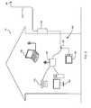
- FIG. 1is a graphical representation of a CATV system arranged in accordance with an embodiment of the present invention
- FIG. 2is a graphical representation of a user's premise arranged in accordance with an embodiment of the present invention
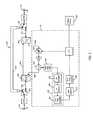
- FIG. 3is a circuit diagram representing a conditioning device including an upstream section made in accordance with another embodiment of the present invention.
- FIG. 4is a circuit diagram representing a coupler used in a conditioning device made in accordance with one embodiment of the present invention.
- FIG. 5is a circuit diagram representing a high pass filter used in a conditioning device made in accordance with one embodiment of the present invention.
- FIG. 6is a circuit diagram representing a RF detection circuit used in a conditioning device made in accordance with one embodiment of the present invention.
- FIG. 7is a circuit diagram representing a level detector used in a conditioning device made in accordance with one embodiment of the present invention.
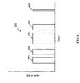
- FIG. 8is a graphical representation of a voltage stream passing from a RF detector to a low-pass amplifier within a RF detection circuit used in a conditioning device made in accordance with one embodiment of the present invention
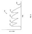
- FIG. 9is a graphical representation of a voltage stream passing from a low-pass amplifier within a RF detection circuit to a level detector used in a conditioning device made in accordance with one embodiment of the present invention.
- FIG. 10is a graphical representation of a voltage stream passing from a level detector to a non-linear amplifier used in a conditioning device made in accordance with one embodiment of the present invention
- FIG. 11is a circuit diagram of a non-linear amplifier used in a conditioning device made in accordance with one embodiment of the present invention.
- FIG. 12is a graphical representation of a theoretical response of a non-linear amplifier in response to a linearly increasing voltage
- FIG. 13is a graphical representation of a voltage stream passing from a non-linear amplifier to a microprocessor used in a conditioning device made in accordance with one embodiment of the present invention.
- FIG. 14is a flow chart representing a signal level measurement routine performed by a microprocessor used in a conditioning device made in accordance with one embodiment of the present invention.
- a CATV systemtypically includes a supplier 20 that transmits a downstream bandwidth, such as RF signals, digital signals, and/or optical signals, to a user through a main distribution system 30 and receives an upstream bandwidth, such as RF signals, digital signals, and/or optical signals, from a user through the same main signal distribution system 30 .
- a tap 90is located at the main signal distribution system 30 to allow for the passage of the downstream/upstream bandwidth from/to the main signal distribution system 30 .
- a drop transmission line 120is then used to connect the tap 90 to a house 10 , 60 an apartment building 50 , 70 , a coffee shop 80 , and so on.
- an upstream bandwidth conditioning device 100 of the present inventionmay be connected in series between the drop transmission line 120 and a user's premise distribution system 130 .
- the upstream bandwidth conditioning device 100can be placed at any location between the tap 90 and the user's premise distribution system 130 . This location can be conveniently located within the premise (e.g., the house 10 , the apartment building 70 , etc.), or proximate to the premise (e.g., the house 60 , the apartment building 50 , etc.). It should be understood that the upstream bandwidth conditioning device 100 can be placed at any location, such as the coffee shop 80 or other business, where CATV services, including internet services, VOIP services, or other unidirectional/bidirectional services are being used.
- the user's premise distribution system 130may be split using a splitter 190 so that downstream/upstream bandwidth can pass to/from a television 150 and a modem 140 in accordance with practices well known in the art.
- the modem 140may include VOIP capabilities affording telephone 170 services and may include a router affording internet services to a desktop computer 160 and a laptop computer 180 , for example.
- STBset-top box
- STUset-top unit
- each upstream bandwidth conditioning device 100may be used with two or more premise devices (e.g., a modem, a STB, a STU, and/or a dedicated VOIP server) that transmit desirable upstream information signals via the upstream bandwidth.
- premise devicese.g., a modem, a STB, a STU, and/or a dedicated VOIP server
- premise deviceis used throughout to describe any one or more of a variety of devices that generate desirable portions of an upstream bandwidth. More specifically, the term premise device is used to describe devices located on or proximate to a user's premise that either receive the downstream bandwidth, transmit information toward the supplier 20 via the upstream bandwidth, or both. These premise devices include internet access modems, STBs, STUs, televisions, premise security monitoring devices, and any future devices that may have a need to report or otherwise provide information via the upstream bandwidth.
- upstream bandwidth conditioning device 100located proximate to two user premises when there is one drop transmission line 120 used to connect the tap 90 to both of the two user premises. Even though such an arrangement is not considered ideal, because the upstream bandwidth from two users may be merged prior to being conditioned, such an arrangement may be necessary when the two premises are located too closely to one another for the physical placement of separate upstream bandwidth conditioning devices 100 .
- the goal of placing the upstream signal conditioning device 100 into one of the locations described aboveis to increase the overall quality of the upstream bandwidth in the main distribution system 30 by increasing the signal-to-noise ratio of the upstream bandwidth leaving the user's premise before that particular user's upstream bandwidth is merged with those of other users.
- merely amplifying the upstream bandwidthfails to achieve the desired result because the undesirable interference signals present in the upstream bandwidth are also amplified.
- upstream bandwidth conditioning device 100will be broken down into two general topics of discussion, general components and an upstream bandwidth conditioning section 105 (“upstream section 105 ”).
- the general componentswill be discussed first to develop the terminology used throughout and to help explain how the upstream bandwidth is passed to the upstream section 105 .
- the hardware, the operation, and the control of the upstream section 105will be discussed thereafter.
- the upstream bandwidth conditioning device 100may include a user side connector 210 and a supplier side connector 215 .
- Each of these connectors 210 , 215may be any of the connectors used in the art for connecting a signal cable to a device.
- each of the user side connector 210 and the supplier side connector 215may be a traditional female “F-type” connector.
- a user side surge protector 220 and a supplier side surge protector 225may be provided electrically adjacent the user side connector 210 and the supplier side connector 215 , respectively. This positioning of the surge protectors 220 , 225 allows for the protection of electrically fragile components (discussed more fully below) positioned between the surge protectors 220 , 225 .
- Each of the user side surge protector 220 and the supplier side surge protector 225may be any of the surge protectors known in the art for electronic applications.
- a user side switch 250 and a supplier side switch 255each have two positions. In a first, default position (shown in FIG. 3 ), the switches 250 , 255 pass signals through a bypass path 230 . In a second position, the user side switch 250 and the supplier side switch 255 electrically connect the user side connector 210 to a user side main path 240 and the supplier side connector 215 to the a supplier side main path 242 , respectively. As will be discussed further below, the primary components of the upstream bandwidth conditioning device 100 are electrically connected in series between the user side main path 240 and the supplier side main path 242 .
- the switches 250 , 255allow the total bandwidth to pass through the bypass path 230 in the event of a fault within the upstream bandwidth conditioning device 100 , such as an electrical power failure.
- the switches 250 , 255may be any of the SPDT (Single Pole Double Throw) switches known in the art.
- the switches 250 , 255may be selected and installed such that when there is no electrical power present to the upstream bandwidth conditioning device 100 , the switches 250 , 255 automatically select the first, default position to pass the total bandwidth through the bypass path 230 .
- the switches 250 , 255move toward their second position passing the total bandwidth to the main paths 240 , 242 .
- a microprocessor 310may also be used to actuate the switches 250 , 255 to their first position (i.e., to the bypass path 230 ) when a fault, other than an electrical power loss, is detected within the upstream bandwidth conditioning device 100 . While the circuitry for such a connection is not shown in FIG. 3 , it should be understood that the control by the microprocessor 310 should be in addition to the switches 250 , 255 automatic positioning due to an electrical failure.
- microprocessorused throughout should be understood to include all active circuits capable of performing the functions discussed herein.
- the microprocessor 310may be replaced with a microcontroller, a system specific digital controller, or a complex analog circuit.
- the bypass path 230may be a coaxial cable, an unshielded wire, and/or a metallic trace on a circuit board. All of these options are capable of passing the total bandwidth with little signal attenuation.
- a user side diplexer 260 and a supplier side diplexer 265are electrically coupled to the user side main path 240 and the supplier side main path 242 , respectfully.
- the diplexers 260 , 265are arranged and configured to create a forward path 244 and a return path 246 , 248 there between.
- Each of the diplexers 260 , 265may function like a combination of a splitter, a high-pass filter, and a low-pass filter, the splitter dividing the respective main path 240 , 242 into two signal paths, one for each of the low-pass filter and the high-pass filter. Using the terms of this combination, each of the high-pass filters passes the downstream bandwidth, and each of the low-pass filters passes the upstream bandwidth.
- the downstream bandwidthpasses along the forward path 244 between the diplexers 260 , 265 .
- the upstream bandwidthpasses along the return path 246 , 248 between the diplexers 260 , 265 .
- the remainder of the description belowfocuses on the hardware, the operation, and the control of the upstream section 105 attached within the return path 246 , 248 .
- the upstream section 105selectively attenuates the upstream bandwidth in increments with the knowledge that a typical premise device will increase the power with which it transmits its portion of the upstream bandwidth (i.e., the desirable upstream bandwidth) to account for the added attenuation. The result is that the desirable upstream bandwidth will be larger in percentage than the remaining portions (i.e., the undesirable upstream bandwidth).
- the upstream section 105must be able to precisely measure the level of the desirable upstream bandwidth in order to increase the amount of attenuation without adding more attenuation than the premise device can account for in terms of increasing its output power. Precise measurements of the desirable upstream bandwidth level are difficult, if not impossible, to make using only traditional level detectors.
- the desirable upstream bandwidthis difficult to measure due to the inherent functional characteristics of premise devices.
- a premise devicetypically transmits a desirable upstream bandwidth only when that premise device is being requested to transmit information.
- a premise devicesuch as an internet access modem, typically transmits information only when a user sends information to the internet. Because there is no way to anticipate when such information is to be sent, the desirable upstream bandwidth created by the premise device must be assumed to be time independent and time discontinuous. Further, the continuity of the information that is being transmitted varies greatly, such as between a simple Pay-Per-View purchase request and an Internet upload of a large, detailed photograph. In other words, the portion of the upstream bandwidth created by a premise device may occur at any time and may occur for any length of time.
- the upstream section 105includes features that are used specifically to identify this time independent and time discontinuous desirable upstream bandwidth.
- the upstream section 105includes a coupler 340 connected within the return path 246 , 248 to pass a portion of the upstream bandwidth, in terms of power and/or frequency range, to subsequent devices in the upstream section 105 via secondary path proceeding from a coupler output 342 ( FIG. 4 ).
- a coupler 340connected within the return path 246 , 248 to pass a portion of the upstream bandwidth, in terms of power and/or frequency range, to subsequent devices in the upstream section 105 via secondary path proceeding from a coupler output 342 ( FIG. 4 ).
- connectionis used throughout to mean optically or electrically positioned such that current, voltages, and/or light are passed between the connected components. It should be understood that the term “connected” does not exclude the possibility of intervening components or devices between the connected components.
- the coupler 340is connected to a RF amplifier 365 even though a high pass filter 350 is shown to be positioned in an intervening relation between the coupler 340 and the RF amplifier.
- connection electrically downstreamand “connected electrically upstream” may also be used throughout to aid in the description regarding where or how the two components are connected.
- the second devicereceives signal from the first device.
- This same arrangementcould also be described as having the first device connected electrically upstream from the second device.
- the high-pass filter 350is connected electrically downstream from the coupler 340 such that the coupler output 342 is electrically connected to a high-pass filter input 352 ( FIG. 5 ).
- the high-pass filter 350is utilized in this instance to pass only a segment of the upstream bandwidth through to the remaining devices, discussed below, via a high-pass filter output 354 ( FIG. 5 ).
- Such a high-pass filter 350may not be required in all instances, but may be beneficial in that it attenuates segments of the upstream bandwidth that are known not to carry the desirable upstream bandwidth.
- the premise devicesare known to provide their desirable upstream bandwidth in a specific segment of the upstream bandwidth, it may be beneficial to configure the high-pass filter 350 to attenuate segments of the upstream bandwidth below the specific segment of the upstream bandwidth where the premise device transmits.
- One skilled in the artwould readily understand, based on the present description and the size requirements of a particular installation, which type of high-pass filter would be suitable for the present purpose. Individual components present in one embodiment of the high-pass filter 350 are represented in FIG. 5 .
- a RF detection circuit 360is connected electrically downstream from the high-pass filter 350 such that the high-pass filter output 354 is electrically connected to a RF detector input 362 ( FIG. 6 ).
- the RF detection circuit 360includes a RF amplifier 365 a RF detector 366 and a low-pass amplifier 367 .
- the RF amplifier 365amplifies the portion of the downstream bandwidth passed through the high-pass filter 350 in preparation for the RF detector 366 .
- the RF detector 366functions as an inverse Laplace transform, the Laplace transform being a widely used integral transform, to convert the portion of the downstream bandwidth from a frequency domain voltage stream into a time domain voltage stream.
- the inverse Laplace transformis given the following complex integral, which is known by various names, the Bromwich integral, the Fourier-Mellin integral, and Mellin's inversion formula.
- An alternative formula for the inverse Laplace transformis given by Post's inversion formula.
- the time domain voltage streamis then passed to the low-pass amplifier 367 , which amplifies the voltages while discriminating in the time between those having suitable signal duration and those that are too short for usage within the following circuitry stages.
- FIG. 8represents a time domain voltage stream output 400 from the RF detector 366 to the low-pass amplifier 367 .
- the time domain voltage stream 400includes increased voltage levels 410 and 420 that last for varying amounts of time.
- Longer sections of increased voltage 410typically represent significant information being sent by a premise device, while shorter sections of increased voltage 420 typically represent “pings,” which are very short bursts of little information.
- These longer sections of increased voltagehave a period that may be typical for a particular premise device.
- the longer sections of increased voltages 410may have shorter or longer sections of lower voltage between the longer sections of increased voltages 410 . This period, which may change based on the types of premise devices present, will be important when discussing a level detector 370 .
- the low-pass amplifier 367creates a voltage stream 402 where the longer periods of increased voltage 410 ( FIG. 8 ) result in higher voltages 412 and where the shorter periods of increased voltage 420 ( FIG. 8 ) result in lower voltages 422 .
- This voltage stream 402is then output to the level detector 370 from a RF detection circuit output 364 .
- a RF detection circuit output 364One skilled in the art would readily understand, based on the present description and the size requirements of a particular installation, which type of components should be used to create the RF detection circuit 360 . Individual components present in one embodiment of the RF detection circuit 360 are represented in FIG. 6 .
- the level detector 370is connected electrically downstream from the RF detection circuit 360 such that the output of the RF detection circuit is electrically connected to a level detector input 372 ( FIG. 7 ).
- the level detector 370generates additional current based on the voltage stream provided by the RF detection circuit 360 , and the level detector 370 includes at least one diode and at least one relatively large capacitor 376 to store the current provided.
- a voltage stream 404 ( FIG. 10 ) provided from the large capacitor 376 to the level detector output 374is relative to the voltage stream 402 provided by the RF detection circuit 360 at the level detector input 372 , except that any increased voltage 412 , 422 is held for a duration longer than that of the voltage stream 402 from the RF detection circuit 360 .
- the amount of duration that any increased voltage is heldis strictly a factor of the sizing of the at least one capacitor, the sizing of an associated resistor, and the current drawn by subsequent devices.
- the level detector 370creates the voltage stream 404 where the longer periods of increased voltage 412 ( FIG. 9 ) are more consistent such that there is less voltage decline between the resulting longer periods of increased voltage 414 .
- This voltage stream 404is then output to a non-linear amplifier 380 from a level detector output 374 .
- the level detector 370Individual components present in one embodiment of the level detector 370 are represented in FIG. 7 . While most of the components are self explanatory to one skilled in the art, it is notable that the level detector 370 made in accordance with one embodiment includes two 10 ⁇ F capacitors 376 sufficient to hold a voltage for up to six seconds. This amount of time has been found to be sufficient to join message voltages 412 ( FIG. 9 ) in the voltage stream 402 ( FIG. 9 ) for the measurements made by the microprocessor 310 , discussed more fully below. The amount of time duration may be less or more depending on the congruity of the messages typically being sent and the speed of the processor 310 .
- the duration needed for the present embodimentis approximately ten times the period of the longer sections of increased voltage 410 provided by the premise device. Accordingly, the duration may change depending on the premise devices present. Further, it should be understood that the term approximately is used here in relation to the “ten times” multiplier because less than ten times may work well enough if a low voltage threshold (“VIL”) is reduced accordingly to allow for greater voltage drops between the longer sections of increased voltage 410 . More than ten times may result in a duration that is too long, where the voltage may not drop soon enough past the VIL to properly stop a series.
- VILlow voltage threshold
- the non-linear amplifier 380is connected electrically downstream from the level detector 370 such that the level detector output 374 is electrically connected to a non-linear amplifier input 382 ( FIG. 11 ).
- the non-linear amplifier 380compresses the voltage stream 404 provided by the level detector 370 to provide additional resolution to lower voltages.
- the non-linear amplifier 380provides additional detail to lower voltages without unnecessarily providing additional resolution to higher voltages. This is important in the present embodiment of the upstream bandwidth conditioning device because the microprocessor 310 accepts a voltage stream from the non-linear amplifier 380 at the non-linear amplifier output 384 ( FIG. 11 ) and converts it to a digital value in the range of 0-255.
- the non-linear amplifier 380is shown in FIG. 11 to include a resistor 386 positioned near the non-linear amplifier input 382 .
- This resistor 386allows for the voltage stream 404 from the level detector 370 to bleed off rather than to maintain a particular voltage indefinitely. Accordingly, it should be understood that this resistor 386 may be considered to be a part of either the level detector 370 or the non-linear amplifier 380 .
- FIG. 12An example of a linearly changing input voltage stream 430 along with a non-linearly changing output voltage stream 440 can be seen in FIG. 12 .
- the output voltage stream 440changes significantly more in relation to any changes in the input voltage stream 430 .
- the output voltage stream 440changes significantly less in relation to any changes in the input voltage stream 430 .
- FIG. 13represents an exemplary output voltage stream 405 produced in response to the voltage stream 404 represented in FIG. 10 .
- the effect of the non-linear amplifier 380is to emphasize details present in the lower voltages while deemphasizing the higher voltages. As mentioned above, this effect of the non-linear amplifier 380 helps provide additional resolution to the lower voltages for measurement purposes.
- the microprocessor 310may be electrically connected downstream from the non-linear amplifier 380 such that the microprocessor 310 is connected to the non-linear amplifier output 384 .
- the microprocessor 310measures the individual voltages from the non-linear amplifier 380 and may convert these voltages into a digital scale of 0-255. It should be understood that the present scale of 0-255 was chosen in the present embodiment only because of the capabilities of the microprocessor 310 . Many other scales, including an actual voltage measurement may also function depending on the capabilities of the microprocessor 310 . Because of these possible differences in measurement value scales, the term “level value” will be used throughout to describe the value assigned to a particular voltage input to the microprocessor 310 for further processing.
- the microprocessor 310works through a series of process steps 500 to determine a level value of the desirable upstream bandwidth generated by a premise device. These level values will be provided to a to an output device 390 ( FIG. 3 ) to be reviewed by a technician for the purpose of conditioning the upstream bandwidth.
- the output device 390may be any one or more of a monitor, a memory device, a network monitoring location, a hand held device, and a printer.
- the level values provided by the process steps 500are a short term average and a long term average.
- the short term averageis an average of a Buffer ⁇ , the Buffer ⁇ having eight input locations ( ⁇ - 7 ).
- the Buffer ⁇ input locationsmay be referred to in two separate manners.
- the Buffer ⁇ input locationsmay be referred to specifically as Buffer ( ⁇ , ⁇ ), Buffer ( ⁇ , 1 ), Buffer ( ⁇ , 2 ), Buffer ( ⁇ , 3 ), Buffer ( ⁇ , 4 ), Buffer ( ⁇ , 5 ), Buffer ( ⁇ , 6 ), and Buffer ( ⁇ , 7 ).
- the Buffer ⁇ input locationsmay be referred to as Buffer ( ⁇ , X), where X is a variable that is increased and reset as part of the process 500 .
- the average of the Buffer ⁇ input locationsis referred to herein as the current average value (“CAV”). Accordingly, the short term average that is output for review by a technician is the CAV.
- the long term averageis an average of a Buffer 1 , the Buffer 1 having eight input locations ( ⁇ - 7 ).
- the Buffer 1 input locationsmay be referred to specifically as Buffer ( 1 , ⁇ ), Buffer ( 1 , 1 ), Buffer ( 1 , 2 ), Buffer ( 1 , 3 ), Buffer ( 1 , 4 ), Buffer ( 1 , 5 ), and Buffer ( 1 , 6 ) and Buffer ( 1 , 7 ).
- the Buffer 1 Input Locationmay be referred to as Buffer ( ⁇ , Y), where Y is a variable that is increased, decreased, and reset as part of the process 500 .
- Each of the Buffer ⁇ and the Buffer 1may include more or less than eight input locations. While it has been found that eight input location works well for the intended purpose of obtaining a level of the upstream bandwidth, more input locations may provide a smoother level value with less volatility. The additional input locations come at a cost of additional time to obtain a level measurement and additional processor consumption.
- the microprocessor 310Upon a powering on of the upstream bandwidth conditioning device 100 , the microprocessor 310 performs an initialization routine, which includes steps 510 , 515 , 520 , and 525 . According to step 510 , the Buffer ⁇ input location X is set to ⁇ and the Buffer 1 input location Y is set to ⁇ . Afterward, the process 500 moves to step 515 .
- step 515the microprocessor 310 checks to see whether the Buffer ⁇ input location X is equal to 8.
- the purpose of step 515is to determine whether Buffer ⁇ is full. The value of 8 is used, because X is incremented by one after a seed value (discussed below) is placed in the last buffer location (i.e. Buffer ( ⁇ , 7 )). Accordingly, even though there is no location “8,” the value of eight is relevant to the present determination. It should be understood that a value of “7” could also be used if the step of incrementing the value of “X” occurs at a different location in the process 500 . If the answer to step 515 is “no,” the microprocessor moves to step 520 . Otherwise, the microprocessor 310 moves to step 525 .
- the microprocessor 310places a seed value into Buffer ( ⁇ , X), which in the first instance is Buffer ( ⁇ , ⁇ ).
- the seed valueis an empirically derived value that is relatively close to the level value anticipated to be found. In other words, the seed value in the present embodiment is experimentally determined based on actual values observed in a particular CATV system.
- the seed valueneeds to be relatively close to the initial level value of the upstream bandwidth to allow the upstream bandwidth conditioning device to start the stabilization process.
- the microprocessorAfter filling Buffer ( ⁇ , X) with the seed value, the microprocessor returns to step 515 to check whether Buffer ⁇ is full. This process between steps 515 and 520 continues to fill all of the Buffer ⁇ input locations with the seed value. Once full, the microprocessor moves to step 525 .
- the microprocessor 310is to obtain a CAV of the Buffer ⁇ , and place that value in Buffer ( 1 , Y), which in this first instance is Buffer ( 1 , ⁇ ).
- the microprocessorresets the Buffer ⁇ input location X to ⁇ , but leaves the seed values in the Buffer ⁇ input locations.
- One skilled in the artwould understand that the present process will function normally if the values in Buffer ⁇ are erased or left as is to be written over at a later time.
- a high voltage limit (“VIH”) and a low voltage limit (“VIL”)are calculated based on the CAV value placed into Buffer ( 1 , Y), which is currently Buffer ( 1 , ⁇ ). Note that this could also be worded as calculating VIH and VIL based on the CAV. Regardless, VIH and VIL are calculated values that are used in later steps to exclude a vast majority of level values that are not near the expected level values. This exclusion helps to make the present upstream bandwidth conditioning device 100 more stable by avoiding mistaken peak value measurements that are far below the expected values.
- VIH and VILare determined after every new CAV is determined, VIH and VIL are allowed to float in the event of a large change in the level values received.
- VIHis to be approximately 94% of the Buffer ( 1 , Y)
- VILis to be approximately 81% of the Buffer ( 1 , Y).
- Both VIH and VILmay be other ratios that allow for more or less level values to be included in any peak value determination. The peak value determination will be discussed further below, but it may be helpful to explain here that VIH sets a high initial threshold where level values below VIH are excluded from consideration.
- VILis a low secondary threshold where level values are considered until a level value of a particular series (a series starting when a level value exceeds VIH) is below VIL.
- a series of level valueswill be examined for a single peak value, the series beginning with a level value exceeding VIH and ending with a level value falling below VIL.
- VIHis calculated to be 48 and VIL is calculated to be 41.
- the microprocessor 310obtains a current level value (“CLV”).
- the CLVis the value of the voltage provided by the non-linear amplifier 380 ( FIG. 3 ) at the current time. Once a CLV is obtained, the microprocessor proceeds to step 535 .
- step 535the microprocessor 310 looks to see whether the recently obtained CLV is greater than VIH to start considering a series of level values. As mentioned above, if the particular CLV is the first obtained value (since having a value fall below VIL) that is greater than VIH, it is the first of a series. Once a series is started, it will continue until a level value is obtained that is less than VIL. Accordingly, if the CLV is below VIH, the microprocessor 310 proceeds to step 540 to determine whether CLV is less than VIL, which if true would stop the series. If the CLV is greater than VIH, the next step is step 560 .
- step 540the microprocessor 310 looks to see whether the recently obtained CLV is less than VIL. As mentioned above, all of the level values obtained that fall below VIL are eliminated from consideration. Rather, than proceeding directly back to step 530 for a new CLV, the process 500 moves to step 545 when the CLV is less than VIL. Accordingly, if the CLV is greater than VIL, the next step is back to step 530 to obtain a new CLV. To continue the series started by having a CLV greater than VIH. It should be understood that any of these comparisons to VIH and VIL may be equal to or less/greater than instead of merely less/greater than. The additional values used or not used would not significantly alter the result.
- step 545a sufficient number of times incrementing the Buffer ⁇ input location X, step 550 will be satisfied indicating that the Buffer ⁇ is ready to be averaged. Accordingly, the microprocessor 310 moves to step 565 .
- the microprocessor 310calculates a CAV, which is the average of Buffer ⁇ and sets the Buffer ⁇ input location X to ⁇ . Also at step 565 , the microprocessor 310 outputs the CAV to one of the devices mentioned above for review and consideration by a technician for the purpose of conditioning the upstream bandwidth. The microprocessor 310 then proceeds to step 570 .
- the microprocessor 310increments the Buffer 1 input location by one. After which, the microprocessor 310 determines whether the Buffer 1 input locations are full in step 580 . Because there are only eight input locations in Buffer 1 , ( ⁇ - 7 ) a value of 8 would indicate that the Buffer 1 is full. The reason for this will become evident below. If the Buffer 1 is full, the next step is step 585 . Otherwise, the next is step 575 .
- step 575the CAV is placed in the next open Buffer 1 input location, Buffer ( 1 , Y). The process then proceeds to step 590 .
- step 585all of the values currently in Buffer 1 are shifted down 1 location such that the value originally (i.e., before step 585 ) in Buffer ( 1 , ⁇ ) is removed from Buffer 1 .
- the CAVis then placed in Buffer ( 1 , 7 ).
- an average of Buffer 1is calculated and output to one of the devices mentioned above for review and consideration by a technician for the purpose of conditioning the upstream bandwidth.
- the Buffer 1 input location Yis set to 7.
- the processproceeds to step 590 .
- the microprocessor 310calculates new values for VIH and VIL from Buffer ( 1 , Y), which may be Buffer ( 1 , 7 ) if step 585 was previously accomplished. After step 590 , the process 500 returns to step 530 to obtain a new CLV and the relevant portions of process 500 are reiterated.
- This process 500continues throughout the operation of the upstream bandwidth conditioning device 100 .
- the microprocessor 310may output the current CAV and/or average of Buffer 1 to the output device 390 . Additionally and in accordance with one embodiment of the present invention, these values may be stored in memory locations either within the microprocessor 310 , or in another circuit for later retrieval and analysis.
Landscapes
- Engineering & Computer Science (AREA)
- Environmental & Geological Engineering (AREA)
- Computer Networks & Wireless Communication (AREA)
- Signal Processing (AREA)
- Amplifiers (AREA)
Abstract
Description
Claims (11)
Priority Applications (5)
| Application Number | Priority Date | Filing Date | Title |
|---|---|---|---|
| US12/576,657US8385219B2 (en) | 2009-10-09 | 2009-10-09 | Upstream bandwidth level measurement device |
| CN2009801508225ACN102257733A (en) | 2008-10-16 | 2009-10-16 | Bandwidth conditioning device |
| PCT/US2009/060997WO2010045552A1 (en) | 2008-10-16 | 2009-10-16 | Bandwidth conditioning device |
| TW98135174ATW201019731A (en) | 2008-10-16 | 2009-10-16 | Bandwidth conditioning device |
| KR1020117010973AKR20110094281A (en) | 2008-10-16 | 2009-10-16 | Bandwidth Regulator |
Applications Claiming Priority (1)
| Application Number | Priority Date | Filing Date | Title |
|---|---|---|---|
| US12/576,657US8385219B2 (en) | 2009-10-09 | 2009-10-09 | Upstream bandwidth level measurement device |
Publications (2)
| Publication Number | Publication Date |
|---|---|
| US20110085452A1 US20110085452A1 (en) | 2011-04-14 |
| US8385219B2true US8385219B2 (en) | 2013-02-26 |
Family
ID=43854765
Family Applications (1)
| Application Number | Title | Priority Date | Filing Date |
|---|---|---|---|
| US12/576,657Expired - Fee RelatedUS8385219B2 (en) | 2008-10-16 | 2009-10-09 | Upstream bandwidth level measurement device |
Country Status (1)
| Country | Link |
|---|---|
| US (1) | US8385219B2 (en) |
Cited By (1)
| Publication number | Priority date | Publication date | Assignee | Title |
|---|---|---|---|---|
| US9807467B2 (en) | 2014-01-21 | 2017-10-31 | Commscope, Inc. | Upstream noise suppression circuits and related radio frequency subscriber drop equipment and methods |
Families Citing this family (18)
| Publication number | Priority date | Publication date | Assignee | Title |
|---|---|---|---|---|
| US9363469B2 (en) | 2008-07-17 | 2016-06-07 | Ppc Broadband, Inc. | Passive-active terminal adapter and method having automatic return loss control |
| US9647851B2 (en) | 2008-10-13 | 2017-05-09 | Ppc Broadband, Inc. | Ingress noise inhibiting network interface device and method for cable television networks |
| US8516537B2 (en)* | 2009-10-09 | 2013-08-20 | Ppc Broadband, Inc. | Downstream bandwidth conditioning device |
| US8464301B2 (en)* | 2008-10-16 | 2013-06-11 | Ppc Broadband, Inc. | Upstream bandwidth conditioning device between CATV distribution system and CATV user |
| US8832767B2 (en)* | 2008-10-16 | 2014-09-09 | Ppc Broadband, Inc. | Dynamically configurable frequency band selection device between CATV distribution system and CATV user |
| US20110085586A1 (en)* | 2009-10-09 | 2011-04-14 | John Mezzalingua Associates, Inc. | Total bandwidth conditioning device |
| US8213457B2 (en)* | 2009-10-09 | 2012-07-03 | John Mezzalingua Associates, Inc. | Upstream bandwidth conditioning device |
| US11910052B2 (en) | 2008-10-21 | 2024-02-20 | Ppc Broadband, Inc. | Entry device for communicating external network signals and in-home network signals |
| US8510782B2 (en) | 2008-10-21 | 2013-08-13 | Ppc Broadband, Inc. | CATV entry adapter and method for preventing interference with eMTA equipment from MoCA Signals |
| US8854947B2 (en)* | 2009-06-15 | 2014-10-07 | Ppc Broadband, Inc. | Device and method for monitoring a communications system |
| US8479247B2 (en) | 2010-04-14 | 2013-07-02 | Ppc Broadband, Inc. | Upstream bandwidth conditioning device |
| US8561125B2 (en) | 2010-08-30 | 2013-10-15 | Ppc Broadband, Inc. | Home network frequency conditioning device and method |
| WO2012088350A2 (en) | 2010-12-21 | 2012-06-28 | John Mezzalingua Associates, Inc. | Method and apparatus for reducing isolation in a home network |
| US10425617B2 (en) | 2016-10-03 | 2019-09-24 | Enseo, Inc. | Distribution element for a self-calibrating RF network and system and method for use of the same |
| US10701569B2 (en) | 2016-10-03 | 2020-06-30 | Enseo, Inc. | Self-calibrating RF network and system and method for use of the same |
| US11831934B2 (en) | 2022-01-11 | 2023-11-28 | Enseo, Llc | Set-top box with self-monitoring and system and method for use of same |
| US10798374B2 (en) | 2016-10-28 | 2020-10-06 | Enseo, Inc. | Set-top box with self-monitoring and system and method for use of same |
| US12212792B2 (en) | 2016-10-28 | 2025-01-28 | Enseo, Llc | Set-top box with self-monitoring and system and method for use of same |
Citations (114)
| Publication number | Priority date | Publication date | Assignee | Title |
|---|---|---|---|---|
| US3790909A (en) | 1973-01-26 | 1974-02-05 | Gte Sylvania Inc | Varactor tuner band switch circuitry |
| JPS5580989A (en) | 1978-12-15 | 1980-06-18 | Nec Corp | Automatic balancing system for exchange |
| JPS55132126A (en) | 1979-03-31 | 1980-10-14 | Fujitsu Ltd | Selective switching circuit of signal transmission line |
| JPS5791055A (en) | 1980-11-27 | 1982-06-07 | Toshiba Corp | Branching device |
| JPS58101582U (en) | 1974-11-14 | 1983-07-11 | エヌ・ベ−・フイリツプス・フル−イランペンフアブリケン | display tube |
| US4418424A (en) | 1980-03-17 | 1983-11-29 | Matsushita Electric Industrial Co., Ltd. | Cable television transmission control system |
| US4512033A (en) | 1982-11-29 | 1985-04-16 | C-Cor Labs, Inc. | Remote level adjustment system for use in a multi-terminal communications system |
| US4520508A (en) | 1982-12-21 | 1985-05-28 | General Instrument Corporation | Subscriber terminal for monitoring radio-frequency signal ingress into cable television systems |
| US4521920A (en)* | 1980-09-01 | 1985-06-04 | Telefonaktiebolaget L M Ericsson | Method and an arrangement for increasing the dynamic range at the input stage of a receiver in an optical fibre information transmission system |
| JPS61157035A (en) | 1984-12-28 | 1986-07-16 | Fujitsu Ltd | Impedance matching system |
| US4648123A (en) | 1982-11-29 | 1987-03-03 | C-Cor Labs, Inc. | Remote level measurement system for use in a multi-terminal communications system |
| US4677390A (en) | 1985-05-31 | 1987-06-30 | Texscan Corporation | Low-power feedforward amplifier |
| US4961218A (en) | 1989-05-17 | 1990-10-02 | Tollgrade Communications, Inc. | Enhanced line powered amplifier |
| US4982440A (en) | 1988-04-21 | 1991-01-01 | Videotron Ltee | CATV network with addressable filters receiving MSK upstream signals |
| US5010399A (en) | 1989-07-14 | 1991-04-23 | Inline Connection Corporation | Video transmission and control system utilizing internal telephone lines |
| US5126840A (en) | 1988-04-21 | 1992-06-30 | Videotron Ltee | Filter circuit receiving upstream signals for use in a CATV network |
| US5214505A (en) | 1991-04-08 | 1993-05-25 | Hughes Aircraft Company | Automatic rf equalization in passenger aircraft video distribution system |
| US5231660A (en) | 1988-03-10 | 1993-07-27 | Scientific-Atlanta, Inc. | Compensation control for off-premises CATV system |
| US5235612A (en) | 1990-12-21 | 1993-08-10 | Motorola, Inc. | Method and apparatus for cancelling spread-spectrum noise |
| US5345504A (en) | 1988-03-10 | 1994-09-06 | Scientific-Atlanta, Inc. | Differential compensation control for off-premises CATV system |
| US5361394A (en) | 1989-12-19 | 1994-11-01 | Kabushiki Kaisha Toshiba | Upstream signal control apparatus for cable television system |
| US5369642A (en) | 1992-05-29 | 1994-11-29 | Nec Corporation | Switcher for redundant signal transmission system |
| US5389882A (en)* | 1990-12-07 | 1995-02-14 | Hewlett-Packard Company | LAN measurement apparatus for determining voltage between packets |
| US5548255A (en) | 1995-06-23 | 1996-08-20 | Microphase Corporation | Compact diplexer connection circuit |
| US5745836A (en) | 1995-09-01 | 1998-04-28 | Cable Television Laboratories, Inc. | Undesirable energy suppression system in a contention based communication network |
| US5815794A (en)* | 1995-09-01 | 1998-09-29 | Cable Television Laboratories, Inc. | Undesirable energy suppression system in the return path of a bidirectional cable network having dynamically allocated time slots |
| US5839052A (en) | 1996-02-08 | 1998-11-17 | Qualcom Incorporated | Method and apparatus for integration of a wireless communication system with a cable television system |
| JPH1169334A (en) | 1997-08-19 | 1999-03-09 | Miharu Tsushin Kk | Standby tv modulator for catv head end |
| US5893024A (en) | 1996-08-13 | 1999-04-06 | Motorola, Inc. | Data communication apparatus and method thereof |
| US5937330A (en) | 1997-02-18 | 1999-08-10 | General Instrument Corporation | Settop terminal controlled return path filter for minimizing noise ingress on bidirectional cable systems |
| US5950111A (en) | 1997-09-25 | 1999-09-07 | Lucent Technologies Inc. | Self-terminating coaxial to unshielded twisted-pair cable passive CATV distribution panel |
| US5956075A (en) | 1996-07-22 | 1999-09-21 | Nec Corporation | CATV terminal unit |
| US5970053A (en) | 1996-12-24 | 1999-10-19 | Rdl, Inc. | Method and apparatus for controlling peak factor of coherent frequency-division-multiplexed systems |
| US6014547A (en) | 1997-04-28 | 2000-01-11 | General Instrument Corporation | System for enhancing the performance of a CATV settop terminal |
| US6049693A (en) | 1996-08-15 | 2000-04-11 | Com21, Inc. | Upstream ingress noise blocking filter for cable television system |
| US6069960A (en) | 1996-09-05 | 2000-05-30 | Sony Corporation | Connector device for information-handling apparatus and connector device for stereophonic audio/video apparatus |
| US6160990A (en) | 1996-05-13 | 2000-12-12 | Kabushiki Kaisha Toshiba | Cable network system with ingress noise suppressing function |
| US6205138B1 (en) | 1998-04-24 | 2001-03-20 | International Business Machines Corporation | Broadband any point to any point switch matrix |
| US6253077B1 (en) | 1997-05-16 | 2001-06-26 | Texas Instruments Incorporated | Downstream power control in point-to-multipoint systems |
| US20010016950A1 (en) | 2000-02-14 | 2001-08-23 | Syuuji Matsuura | Cable modem tuner |
| US6348837B1 (en) | 2000-08-08 | 2002-02-19 | Scientific-Atlanta, Inc. | Bi-directional amplifier having a single gain block for amplifying both forward and reverse signals |
| US6348955B1 (en) | 1998-02-23 | 2002-02-19 | Zenith Electronics Corporation | Tuner with switched analog and digital demodulators |
| US6373349B2 (en) | 2000-03-17 | 2002-04-16 | Bae Systems Information And Electronic Systems Integration Inc. | Reconfigurable diplexer for communications applications |
| US6377316B1 (en) | 1998-02-23 | 2002-04-23 | Zenith Electronics Corporation | Tuner with switched analog and digital modulators |
| US6388539B1 (en) | 2001-04-16 | 2002-05-14 | At&T Corp. | Broadband switch/coupler |
| US6425132B1 (en) | 1998-04-06 | 2002-07-23 | Wavetek Corporation | Ingress testing of CATV system utilizing remote selection of CATV node |
| US20020144292A1 (en) | 2001-02-19 | 2002-10-03 | Jun Uemura | Bi-directional CATV system, line equipment, center equipment |
| US20020141494A1 (en) | 2001-03-29 | 2002-10-03 | Chappell Daniel K. | Sweep method using digital signals |
| US20020141347A1 (en) | 2001-03-30 | 2002-10-03 | Harp Jeffrey C. | System and method of reducing ingress noise |
| US20020166124A1 (en) | 2001-05-04 | 2002-11-07 | Itzhak Gurantz | Network interface device and broadband local area network using coaxial cable |
| US20020174435A1 (en) | 2001-02-27 | 2002-11-21 | Hillel Weinstein | System, apparatus and method for expanding the operational bandwidth of a communication system |
| US6495998B1 (en) | 2000-09-28 | 2002-12-17 | Sunrise Telecom Corp. | Selectable band-pass filtering apparatus and method |
| US6498925B1 (en) | 1999-05-13 | 2002-12-24 | Denso Corporation | Transmit power control circuit |
| US6510152B1 (en) | 1997-12-31 | 2003-01-21 | At&T Corp. | Coaxial cable/twisted pair fed, integrated residence gateway controlled, set-top box |
| US6560778B1 (en) | 1999-03-29 | 2003-05-06 | Masprodenkoh Kabushikikaisha | Tap device of cable broadcasting system |
| US6570914B1 (en)* | 1999-07-07 | 2003-05-27 | Nec Corporation | Amplitude calculation circuit |
| US6570928B1 (en) | 1999-01-05 | 2003-05-27 | Masprodenkoh Kabushikikaisha | Cable broadcasting system |
| US6587012B1 (en) | 1999-10-01 | 2003-07-01 | Arris International, Inc. | Automatic slope and gain (ASG) detector technique including a pilot signal |
| US6622304B1 (en) | 1996-09-09 | 2003-09-16 | Thomas W. Carhart | Interface system for computing apparatus and communications stations |
| US6640338B1 (en) | 1999-01-27 | 2003-10-28 | Masprodenkoh Kabushikikaisha | Electronic device for cable broadcasting system |
| US6678893B1 (en) | 1997-12-26 | 2004-01-13 | Samsung Electronics Co., Ltd. | Bidirectional trunk amplifier and cable modem for cable hybrid fiber and coax network which utilizes an upstream pilot signal |
| US6683513B2 (en) | 2000-10-26 | 2004-01-27 | Paratek Microwave, Inc. | Electronically tunable RF diplexers tuned by tunable capacitors |
| JP2004080483A (en) | 2002-08-20 | 2004-03-11 | Ntt Communications Kk | Adapter for VoIP |
| US6725463B1 (en) | 1997-08-01 | 2004-04-20 | Microtune (Texas), L.P. | Dual mode tuner for co-existing digital and analog television signals |
| US6725462B1 (en) | 2000-04-19 | 2004-04-20 | At&T Corp. | Optimizing upstream transmission in a cable television distribution plant |
| US20040076192A1 (en)* | 1999-10-19 | 2004-04-22 | Rambus Inc. | Calibrated data communication system and method |
| US6728968B1 (en) | 1999-06-17 | 2004-04-27 | Fujitsu Limited | Upward-joining-noise decreasing method and apparatus |
| US6757910B1 (en) | 2000-06-08 | 2004-06-29 | C-Cor.Net Corporation | Adaptive filter for reducing ingress noise in CATV return signals |
| US20040172659A1 (en) | 2001-07-13 | 2004-09-02 | Ljungdahl Kjell Arne | Arrangement for reduction of noise transmitted from a local cable tv network |
| US6804828B1 (en) | 1998-12-03 | 2004-10-12 | Masprodenkoh Kabushikikaisha | Tap device of cable broadcasting system |
| US20040229561A1 (en) | 2003-02-28 | 2004-11-18 | Cowley Nicholas Paul | Tuner |
| JP2005005875A (en) | 2003-06-10 | 2005-01-06 | Nec Tohoku Ltd | VoIP SWITCHING DEVICE |
| US6845232B2 (en) | 2002-03-25 | 2005-01-18 | Broadcom Corporation | Analog peak detection circuitry for radio receivers |
| US20050034168A1 (en) | 1993-05-28 | 2005-02-10 | Mediaone Group, Inc. | Method and apparatus for delivering secured telephony service in a hybrid coaxial cable network |
| US6877166B1 (en) | 2000-01-18 | 2005-04-05 | Cisco Technology, Inc. | Intelligent power level adjustment for cable modems in presence of noise |
| US6880170B1 (en)* | 1994-11-30 | 2005-04-12 | General Instrument Corporation | Ingress detection and attenuation |
| US20050155082A1 (en) | 2001-02-27 | 2005-07-14 | Hillel Weinstein | Device, system and method for connecting a subscriber device to a wideband distribution network |
| US6928175B1 (en) | 2000-06-14 | 2005-08-09 | Creative Technology Ltd. | Audio system with optional auto-switching secondary connector, and method for same |
| US20050183130A1 (en) | 2004-02-12 | 2005-08-18 | Sadja Aran L. | Cable diagnostic and monitoring system |
| US20050283815A1 (en) | 2004-06-01 | 2005-12-22 | Brooks Paul D | Apparatus and methods for network interface and spectrum management |
| US20050289632A1 (en) | 2004-06-01 | 2005-12-29 | Brooks Paul D | Controlled isolation splitter apparatus and methods |
| US20060015921A1 (en) | 2004-07-19 | 2006-01-19 | Jay Vaughan | VoIP drop amplifier |
| US7003275B1 (en) | 2000-05-18 | 2006-02-21 | Broadband Innovations, Inc. | Agile frequency converter for multichannel systems using IF-RF level exhange and tunable filters |
| US7029293B2 (en) | 2004-08-20 | 2006-04-18 | Extreme Broadband Engineering, Llc | Ground block connector |
| US7039432B2 (en) | 2001-12-04 | 2006-05-02 | General Instrument Corporation | Dynamic upstream attenuation for ingress noise reduction |
| US20060205442A1 (en) | 2005-03-10 | 2006-09-14 | Neil Phillips | Bi-directional amplifier with non-interruptible port |
| US20060282871A1 (en) | 2005-06-13 | 2006-12-14 | Yao-Tsan Yo | Distribution method for noise control |
| US7162731B2 (en) | 2002-02-07 | 2007-01-09 | Advent Networks, Inc. | Radio frequency characterization of cable plant and corresponding calibration of communication equipment communicating via the cable plant |
| US7167693B2 (en)* | 2001-03-06 | 2007-01-23 | Andrew Corporation | Scanning receiver for use in power amplifier linearization |
| JP2007166109A (en) | 2005-12-12 | 2007-06-28 | Matsushita Electric Works Ltd | Branch device of transmission system, and transmission system |
| JP2007166110A (en) | 2005-12-12 | 2007-06-28 | Matsushita Electric Works Ltd | Transmission system and branch device thereof |
| US7283479B2 (en) | 2000-02-16 | 2007-10-16 | Spacenet Proxilliant Systems Ab | Cable TV system or other similar communication system |
| US20070288981A1 (en) | 2006-06-13 | 2007-12-13 | Hwa Lin Electronic (Shenzhen)Co., Ltd. | CATV system and automatic noise controller |
| US20070288982A1 (en) | 2006-06-13 | 2007-12-13 | Comcast Cable Holdings, Llc | Dynamic ingress arrester |
| US20080022344A1 (en) | 2006-07-07 | 2008-01-24 | Scientific-Atlanta, Inc. | Format Converter with Smart Multitap with Digital Forward and Reverse |
| US20080040764A1 (en) | 2001-07-20 | 2008-02-14 | Hillel Weinstein | System, apparatus and method for expanding the operational bandwidth of a communication system |
| US20080075012A1 (en)* | 2006-09-25 | 2008-03-27 | Zielinski Stephen A | Handheld field maintenance bus monitor |
| US20080127287A1 (en) | 2006-11-28 | 2008-05-29 | John Mezzalingua Associates, Inc. | Apparatus and method for embedding/detecting an auxiliary signal within a catv traffic stream |
| US7454252B2 (en) | 2006-03-08 | 2008-11-18 | Moore Industries International, Inc. | Redundant fieldbus system |
| US20090031391A1 (en) | 2007-03-08 | 2009-01-29 | Emerson Network Power Connectivity Solutions | Electronically controlled catv system |
| US20090047917A1 (en) | 2005-03-10 | 2009-02-19 | Phillips Neil P | Signal Amplifiers Having Non-Interruptible Communication Paths |
| US7505819B2 (en) | 2006-02-08 | 2009-03-17 | Moore Industries International, Inc. | Redundant fieldbus system |
| US20090077608A1 (en) | 2007-09-14 | 2009-03-19 | Romerein Robert L | Constant input port impedance for CATV amplifier with passive modem port |
| US20090154369A1 (en)* | 2007-12-18 | 2009-06-18 | Helvig William J | Digital-channel-monitor unit |
| US7603693B2 (en) | 2002-05-15 | 2009-10-13 | Panasonic Corporation | CATV uplink optical transmission system |
| US20090320085A1 (en)* | 2008-06-23 | 2009-12-24 | Jon-En Wang | House amplifier with return path gating |
| US20090316608A1 (en) | 2008-06-24 | 2009-12-24 | Lgc Wireless, Inc. | System and method for configurable time-division duplex interface |
| US20100100921A1 (en) | 2008-10-16 | 2010-04-22 | John Mezzalingua Associates, Inc. | Dynamically configurable frequency band selection device between catv distribution system and catv user |
| US20100100912A1 (en) | 2008-10-16 | 2010-04-22 | John Mezzalingua Associates, Inc. | Upstream bandwidth conditioning device between catv distribution system and catv user |
| US20100266000A1 (en) | 2009-04-20 | 2010-10-21 | Texas Instruments Incorporated | Discrete spurious leakage cancellation for use in a cable modem |
| US20110088077A1 (en) | 2009-10-09 | 2011-04-14 | John Mezzalingua Associates, Inc. | Downstream bandwidth conditioning device |
| US20110085586A1 (en) | 2009-10-09 | 2011-04-14 | John Mezzalingua Associates, Inc. | Total bandwidth conditioning device |
| US20110085480A1 (en) | 2009-10-09 | 2011-04-14 | John Mezzalingua Associates, Inc. | Upstream bandwidth conditioning device |
| US8001579B2 (en) | 2008-10-16 | 2011-08-16 | John Mezzalingua Associates, Inc. | Downstream output level and/or output level tilt compensation device between CATV distribution system and CATV user |
- 2009
- 2009-10-09USUS12/576,657patent/US8385219B2/ennot_activeExpired - Fee Related
Patent Citations (120)
| Publication number | Priority date | Publication date | Assignee | Title |
|---|---|---|---|---|
| US3790909A (en) | 1973-01-26 | 1974-02-05 | Gte Sylvania Inc | Varactor tuner band switch circuitry |
| JPS58101582U (en) | 1974-11-14 | 1983-07-11 | エヌ・ベ−・フイリツプス・フル−イランペンフアブリケン | display tube |
| JPS5580989A (en) | 1978-12-15 | 1980-06-18 | Nec Corp | Automatic balancing system for exchange |
| JPS55132126A (en) | 1979-03-31 | 1980-10-14 | Fujitsu Ltd | Selective switching circuit of signal transmission line |
| US4418424A (en) | 1980-03-17 | 1983-11-29 | Matsushita Electric Industrial Co., Ltd. | Cable television transmission control system |
| US4521920A (en)* | 1980-09-01 | 1985-06-04 | Telefonaktiebolaget L M Ericsson | Method and an arrangement for increasing the dynamic range at the input stage of a receiver in an optical fibre information transmission system |
| JPS5791055A (en) | 1980-11-27 | 1982-06-07 | Toshiba Corp | Branching device |
| US4512033A (en) | 1982-11-29 | 1985-04-16 | C-Cor Labs, Inc. | Remote level adjustment system for use in a multi-terminal communications system |
| US4648123A (en) | 1982-11-29 | 1987-03-03 | C-Cor Labs, Inc. | Remote level measurement system for use in a multi-terminal communications system |
| US4520508A (en) | 1982-12-21 | 1985-05-28 | General Instrument Corporation | Subscriber terminal for monitoring radio-frequency signal ingress into cable television systems |
| JPS61157035A (en) | 1984-12-28 | 1986-07-16 | Fujitsu Ltd | Impedance matching system |
| US4677390A (en) | 1985-05-31 | 1987-06-30 | Texscan Corporation | Low-power feedforward amplifier |
| US5345504A (en) | 1988-03-10 | 1994-09-06 | Scientific-Atlanta, Inc. | Differential compensation control for off-premises CATV system |
| US5231660A (en) | 1988-03-10 | 1993-07-27 | Scientific-Atlanta, Inc. | Compensation control for off-premises CATV system |
| US4982440A (en) | 1988-04-21 | 1991-01-01 | Videotron Ltee | CATV network with addressable filters receiving MSK upstream signals |
| US5126840A (en) | 1988-04-21 | 1992-06-30 | Videotron Ltee | Filter circuit receiving upstream signals for use in a CATV network |
| US4961218A (en) | 1989-05-17 | 1990-10-02 | Tollgrade Communications, Inc. | Enhanced line powered amplifier |
| US5010399A (en) | 1989-07-14 | 1991-04-23 | Inline Connection Corporation | Video transmission and control system utilizing internal telephone lines |
| US5361394A (en) | 1989-12-19 | 1994-11-01 | Kabushiki Kaisha Toshiba | Upstream signal control apparatus for cable television system |
| US5389882A (en)* | 1990-12-07 | 1995-02-14 | Hewlett-Packard Company | LAN measurement apparatus for determining voltage between packets |
| US5235612A (en) | 1990-12-21 | 1993-08-10 | Motorola, Inc. | Method and apparatus for cancelling spread-spectrum noise |
| US5214505A (en) | 1991-04-08 | 1993-05-25 | Hughes Aircraft Company | Automatic rf equalization in passenger aircraft video distribution system |
| US5369642A (en) | 1992-05-29 | 1994-11-29 | Nec Corporation | Switcher for redundant signal transmission system |
| US20050034168A1 (en) | 1993-05-28 | 2005-02-10 | Mediaone Group, Inc. | Method and apparatus for delivering secured telephony service in a hybrid coaxial cable network |
| US6880170B1 (en)* | 1994-11-30 | 2005-04-12 | General Instrument Corporation | Ingress detection and attenuation |
| US5548255A (en) | 1995-06-23 | 1996-08-20 | Microphase Corporation | Compact diplexer connection circuit |
| US5745836A (en) | 1995-09-01 | 1998-04-28 | Cable Television Laboratories, Inc. | Undesirable energy suppression system in a contention based communication network |
| US5815794A (en)* | 1995-09-01 | 1998-09-29 | Cable Television Laboratories, Inc. | Undesirable energy suppression system in the return path of a bidirectional cable network having dynamically allocated time slots |
| US5839052A (en) | 1996-02-08 | 1998-11-17 | Qualcom Incorporated | Method and apparatus for integration of a wireless communication system with a cable television system |
| US6160990A (en) | 1996-05-13 | 2000-12-12 | Kabushiki Kaisha Toshiba | Cable network system with ingress noise suppressing function |
| US5956075A (en) | 1996-07-22 | 1999-09-21 | Nec Corporation | CATV terminal unit |
| US5893024A (en) | 1996-08-13 | 1999-04-06 | Motorola, Inc. | Data communication apparatus and method thereof |
| US6049693A (en) | 1996-08-15 | 2000-04-11 | Com21, Inc. | Upstream ingress noise blocking filter for cable television system |
| US6094211A (en) | 1996-08-15 | 2000-07-25 | Com21, Inc. | TV and data cable system ingress noise blocker |
| US6069960A (en) | 1996-09-05 | 2000-05-30 | Sony Corporation | Connector device for information-handling apparatus and connector device for stereophonic audio/video apparatus |
| US6622304B1 (en) | 1996-09-09 | 2003-09-16 | Thomas W. Carhart | Interface system for computing apparatus and communications stations |
| US5970053A (en) | 1996-12-24 | 1999-10-19 | Rdl, Inc. | Method and apparatus for controlling peak factor of coherent frequency-division-multiplexed systems |
| US5937330A (en) | 1997-02-18 | 1999-08-10 | General Instrument Corporation | Settop terminal controlled return path filter for minimizing noise ingress on bidirectional cable systems |
| US6014547A (en) | 1997-04-28 | 2000-01-11 | General Instrument Corporation | System for enhancing the performance of a CATV settop terminal |
| US6253077B1 (en) | 1997-05-16 | 2001-06-26 | Texas Instruments Incorporated | Downstream power control in point-to-multipoint systems |
| US6725463B1 (en) | 1997-08-01 | 2004-04-20 | Microtune (Texas), L.P. | Dual mode tuner for co-existing digital and analog television signals |
| JPH1169334A (en) | 1997-08-19 | 1999-03-09 | Miharu Tsushin Kk | Standby tv modulator for catv head end |
| US5950111A (en) | 1997-09-25 | 1999-09-07 | Lucent Technologies Inc. | Self-terminating coaxial to unshielded twisted-pair cable passive CATV distribution panel |
| US6678893B1 (en) | 1997-12-26 | 2004-01-13 | Samsung Electronics Co., Ltd. | Bidirectional trunk amplifier and cable modem for cable hybrid fiber and coax network which utilizes an upstream pilot signal |
| US6510152B1 (en) | 1997-12-31 | 2003-01-21 | At&T Corp. | Coaxial cable/twisted pair fed, integrated residence gateway controlled, set-top box |
| US6348955B1 (en) | 1998-02-23 | 2002-02-19 | Zenith Electronics Corporation | Tuner with switched analog and digital demodulators |
| US6377316B1 (en) | 1998-02-23 | 2002-04-23 | Zenith Electronics Corporation | Tuner with switched analog and digital modulators |
| US6425132B1 (en) | 1998-04-06 | 2002-07-23 | Wavetek Corporation | Ingress testing of CATV system utilizing remote selection of CATV node |
| US6205138B1 (en) | 1998-04-24 | 2001-03-20 | International Business Machines Corporation | Broadband any point to any point switch matrix |
| US6804828B1 (en) | 1998-12-03 | 2004-10-12 | Masprodenkoh Kabushikikaisha | Tap device of cable broadcasting system |
| US6570928B1 (en) | 1999-01-05 | 2003-05-27 | Masprodenkoh Kabushikikaisha | Cable broadcasting system |
| US6640338B1 (en) | 1999-01-27 | 2003-10-28 | Masprodenkoh Kabushikikaisha | Electronic device for cable broadcasting system |
| US6560778B1 (en) | 1999-03-29 | 2003-05-06 | Masprodenkoh Kabushikikaisha | Tap device of cable broadcasting system |
| US6498925B1 (en) | 1999-05-13 | 2002-12-24 | Denso Corporation | Transmit power control circuit |
| US6728968B1 (en) | 1999-06-17 | 2004-04-27 | Fujitsu Limited | Upward-joining-noise decreasing method and apparatus |
| US6570914B1 (en)* | 1999-07-07 | 2003-05-27 | Nec Corporation | Amplitude calculation circuit |
| US6587012B1 (en) | 1999-10-01 | 2003-07-01 | Arris International, Inc. | Automatic slope and gain (ASG) detector technique including a pilot signal |
| US20040076192A1 (en)* | 1999-10-19 | 2004-04-22 | Rambus Inc. | Calibrated data communication system and method |
| US6877166B1 (en) | 2000-01-18 | 2005-04-05 | Cisco Technology, Inc. | Intelligent power level adjustment for cable modems in presence of noise |
| US20010016950A1 (en) | 2000-02-14 | 2001-08-23 | Syuuji Matsuura | Cable modem tuner |
| US7283479B2 (en) | 2000-02-16 | 2007-10-16 | Spacenet Proxilliant Systems Ab | Cable TV system or other similar communication system |
| US6373349B2 (en) | 2000-03-17 | 2002-04-16 | Bae Systems Information And Electronic Systems Integration Inc. | Reconfigurable diplexer for communications applications |
| US6725462B1 (en) | 2000-04-19 | 2004-04-20 | At&T Corp. | Optimizing upstream transmission in a cable television distribution plant |
| US7003275B1 (en) | 2000-05-18 | 2006-02-21 | Broadband Innovations, Inc. | Agile frequency converter for multichannel systems using IF-RF level exhange and tunable filters |
| US6757910B1 (en) | 2000-06-08 | 2004-06-29 | C-Cor.Net Corporation | Adaptive filter for reducing ingress noise in CATV return signals |
| US6928175B1 (en) | 2000-06-14 | 2005-08-09 | Creative Technology Ltd. | Audio system with optional auto-switching secondary connector, and method for same |
| US6348837B1 (en) | 2000-08-08 | 2002-02-19 | Scientific-Atlanta, Inc. | Bi-directional amplifier having a single gain block for amplifying both forward and reverse signals |
| US6495998B1 (en) | 2000-09-28 | 2002-12-17 | Sunrise Telecom Corp. | Selectable band-pass filtering apparatus and method |
| US6683513B2 (en) | 2000-10-26 | 2004-01-27 | Paratek Microwave, Inc. | Electronically tunable RF diplexers tuned by tunable capacitors |
| US20020144292A1 (en) | 2001-02-19 | 2002-10-03 | Jun Uemura | Bi-directional CATV system, line equipment, center equipment |
| US7748023B2 (en) | 2001-02-27 | 2010-06-29 | Xtend Networks Ltd. | Device, system and method for connecting a subscriber device to a wideband distribution network |
| US20050155082A1 (en) | 2001-02-27 | 2005-07-14 | Hillel Weinstein | Device, system and method for connecting a subscriber device to a wideband distribution network |
| US20020174435A1 (en) | 2001-02-27 | 2002-11-21 | Hillel Weinstein | System, apparatus and method for expanding the operational bandwidth of a communication system |
| US7167693B2 (en)* | 2001-03-06 | 2007-01-23 | Andrew Corporation | Scanning receiver for use in power amplifier linearization |
| US20020141494A1 (en) | 2001-03-29 | 2002-10-03 | Chappell Daniel K. | Sweep method using digital signals |
| US20020141347A1 (en) | 2001-03-30 | 2002-10-03 | Harp Jeffrey C. | System and method of reducing ingress noise |
| US6388539B1 (en) | 2001-04-16 | 2002-05-14 | At&T Corp. | Broadband switch/coupler |
| US20020166124A1 (en) | 2001-05-04 | 2002-11-07 | Itzhak Gurantz | Network interface device and broadband local area network using coaxial cable |
| US20040172659A1 (en) | 2001-07-13 | 2004-09-02 | Ljungdahl Kjell Arne | Arrangement for reduction of noise transmitted from a local cable tv network |
| US20080040764A1 (en) | 2001-07-20 | 2008-02-14 | Hillel Weinstein | System, apparatus and method for expanding the operational bandwidth of a communication system |
| US7742777B2 (en) | 2001-12-04 | 2010-06-22 | General Instrument Corporation | Dynamic upstream attenuation for ingress noise reduction |
| US7039432B2 (en) | 2001-12-04 | 2006-05-02 | General Instrument Corporation | Dynamic upstream attenuation for ingress noise reduction |
| US20060148406A1 (en) | 2001-12-04 | 2006-07-06 | Jay Strater | Dynamic upstream attenuation for ingress noise reduction |
| US7162731B2 (en) | 2002-02-07 | 2007-01-09 | Advent Networks, Inc. | Radio frequency characterization of cable plant and corresponding calibration of communication equipment communicating via the cable plant |
| US6845232B2 (en) | 2002-03-25 | 2005-01-18 | Broadcom Corporation | Analog peak detection circuitry for radio receivers |
| US7603693B2 (en) | 2002-05-15 | 2009-10-13 | Panasonic Corporation | CATV uplink optical transmission system |
| JP2004080483A (en) | 2002-08-20 | 2004-03-11 | Ntt Communications Kk | Adapter for VoIP |
| US20040229561A1 (en) | 2003-02-28 | 2004-11-18 | Cowley Nicholas Paul | Tuner |
| JP2005005875A (en) | 2003-06-10 | 2005-01-06 | Nec Tohoku Ltd | VoIP SWITCHING DEVICE |
| US20050183130A1 (en) | 2004-02-12 | 2005-08-18 | Sadja Aran L. | Cable diagnostic and monitoring system |
| US20050289632A1 (en) | 2004-06-01 | 2005-12-29 | Brooks Paul D | Controlled isolation splitter apparatus and methods |
| US20050283815A1 (en) | 2004-06-01 | 2005-12-22 | Brooks Paul D | Apparatus and methods for network interface and spectrum management |
| US20060015921A1 (en) | 2004-07-19 | 2006-01-19 | Jay Vaughan | VoIP drop amplifier |
| US7530091B2 (en) | 2004-07-19 | 2009-05-05 | Pct International, Inc. | VOIP drop amplifier |
| US7029293B2 (en) | 2004-08-20 | 2006-04-18 | Extreme Broadband Engineering, Llc | Ground block connector |
| US20060205442A1 (en) | 2005-03-10 | 2006-09-14 | Neil Phillips | Bi-directional amplifier with non-interruptible port |
| US20090047917A1 (en) | 2005-03-10 | 2009-02-19 | Phillips Neil P | Signal Amplifiers Having Non-Interruptible Communication Paths |
| US20060282871A1 (en) | 2005-06-13 | 2006-12-14 | Yao-Tsan Yo | Distribution method for noise control |
| JP2007166109A (en) | 2005-12-12 | 2007-06-28 | Matsushita Electric Works Ltd | Branch device of transmission system, and transmission system |
| JP2007166110A (en) | 2005-12-12 | 2007-06-28 | Matsushita Electric Works Ltd | Transmission system and branch device thereof |
| US7505819B2 (en) | 2006-02-08 | 2009-03-17 | Moore Industries International, Inc. | Redundant fieldbus system |
| US7454252B2 (en) | 2006-03-08 | 2008-11-18 | Moore Industries International, Inc. | Redundant fieldbus system |
| US20070288982A1 (en) | 2006-06-13 | 2007-12-13 | Comcast Cable Holdings, Llc | Dynamic ingress arrester |
| US20070288981A1 (en) | 2006-06-13 | 2007-12-13 | Hwa Lin Electronic (Shenzhen)Co., Ltd. | CATV system and automatic noise controller |
| US20080022344A1 (en) | 2006-07-07 | 2008-01-24 | Scientific-Atlanta, Inc. | Format Converter with Smart Multitap with Digital Forward and Reverse |
| US20080075012A1 (en)* | 2006-09-25 | 2008-03-27 | Zielinski Stephen A | Handheld field maintenance bus monitor |
| US20080127287A1 (en) | 2006-11-28 | 2008-05-29 | John Mezzalingua Associates, Inc. | Apparatus and method for embedding/detecting an auxiliary signal within a catv traffic stream |
| US20090031391A1 (en) | 2007-03-08 | 2009-01-29 | Emerson Network Power Connectivity Solutions | Electronically controlled catv system |
| US20090077608A1 (en) | 2007-09-14 | 2009-03-19 | Romerein Robert L | Constant input port impedance for CATV amplifier with passive modem port |
| US20090154369A1 (en)* | 2007-12-18 | 2009-06-18 | Helvig William J | Digital-channel-monitor unit |
| US20090320085A1 (en)* | 2008-06-23 | 2009-12-24 | Jon-En Wang | House amplifier with return path gating |
| US20090316608A1 (en) | 2008-06-24 | 2009-12-24 | Lgc Wireless, Inc. | System and method for configurable time-division duplex interface |
| US20100100912A1 (en) | 2008-10-16 | 2010-04-22 | John Mezzalingua Associates, Inc. | Upstream bandwidth conditioning device between catv distribution system and catv user |
| US20100100921A1 (en) | 2008-10-16 | 2010-04-22 | John Mezzalingua Associates, Inc. | Dynamically configurable frequency band selection device between catv distribution system and catv user |
| US8001579B2 (en) | 2008-10-16 | 2011-08-16 | John Mezzalingua Associates, Inc. | Downstream output level and/or output level tilt compensation device between CATV distribution system and CATV user |
| US20100266000A1 (en) | 2009-04-20 | 2010-10-21 | Texas Instruments Incorporated | Discrete spurious leakage cancellation for use in a cable modem |
| US20110088077A1 (en) | 2009-10-09 | 2011-04-14 | John Mezzalingua Associates, Inc. | Downstream bandwidth conditioning device |
| US20110085586A1 (en) | 2009-10-09 | 2011-04-14 | John Mezzalingua Associates, Inc. | Total bandwidth conditioning device |
| US20110085480A1 (en) | 2009-10-09 | 2011-04-14 | John Mezzalingua Associates, Inc. | Upstream bandwidth conditioning device |
| US8213457B2 (en) | 2009-10-09 | 2012-07-03 | John Mezzalingua Associates, Inc. | Upstream bandwidth conditioning device |
Non-Patent Citations (1)
| Title |
|---|
| International Searching Authority/US, International Search Report and Written Opinion dated Dec. 18, 2009 (7 pgs). |
Cited By (2)
| Publication number | Priority date | Publication date | Assignee | Title |
|---|---|---|---|---|
| US9807467B2 (en) | 2014-01-21 | 2017-10-31 | Commscope, Inc. | Upstream noise suppression circuits and related radio frequency subscriber drop equipment and methods |
| US10484748B2 (en) | 2014-01-21 | 2019-11-19 | Commscope, Inc. | Upstream noise suppression circuits and related radio frequency subscriber drop equipment and methods |
Also Published As
| Publication number | Publication date |
|---|---|
| US20110085452A1 (en) | 2011-04-14 |
Similar Documents
| Publication | Publication Date | Title |
|---|---|---|
| US8385219B2 (en) | Upstream bandwidth level measurement device | |
| US8213457B2 (en) | Upstream bandwidth conditioning device | |
| US8479247B2 (en) | Upstream bandwidth conditioning device | |
| US20110085586A1 (en) | Total bandwidth conditioning device | |
| US8516537B2 (en) | Downstream bandwidth conditioning device | |
| US8179814B2 (en) | Automatic return path switching for a signal conditioning device | |
| US8181211B2 (en) | Total bandwidth conditioning device | |
| US10264325B2 (en) | System, method and device having teaching and commerce subsystems | |
| US7757262B2 (en) | CATV system and automatic noise controller | |
| US8584192B2 (en) | Upstream bandwidth conditioning device | |
| US20130091267A1 (en) | Smart Gateway | |
| US20100100912A1 (en) | Upstream bandwidth conditioning device between catv distribution system and catv user | |
| US20100251322A1 (en) | Upstream bandwidth conditioning device | |
| WO2010117496A2 (en) | Upstream bandwidth conditioning device | |
| WO2010045552A1 (en) | Bandwidth conditioning device | |
| US20110085045A1 (en) | Modulation analyzer and level measurement device | |
| US20050226164A1 (en) | Power line induction of sheath test current to discover defective coaxial cable | |
| US8059208B2 (en) | Line tapping method of video amplification for unshielded twisted pair active receiver | |
| US7999609B2 (en) | Managed wideband radio frequency distribution system with signal level enabling interface device and impedance signature detection | |
| US20230254443A1 (en) | Passive entry adapter system for a catv network | |
| US20120213083A1 (en) | Home network test circuit | |
| US8141122B2 (en) | RF terminate/permit system | |
| WO2019226219A1 (en) | Systems and methods for suppressing radiofrequency noise from a modem | |
| CN202679315U (en) | Distribution amplifier with noise suppression circuit | |
| US20250317108A1 (en) | System and Process for Automatic Analysis and Optimization of Amplifiers |
Legal Events
| Date | Code | Title | Description |
|---|---|---|---|
| AS | Assignment | Owner name:JOHN MEZZALINGUA ASSOCIATES, INC., NEW YORK Free format text:ASSIGNMENT OF ASSIGNORS INTEREST;ASSIGNORS:KELMA, DAVID;COX, TAB KENDALL;REEL/FRAME:023353/0138 Effective date:20091007 | |
| STCF | Information on status: patent grant | Free format text:PATENTED CASE | |
| AS | Assignment | Owner name:MR ADVISERS LIMITED, NEW YORK Free format text:CHANGE OF NAME;ASSIGNOR:JOHN MEZZALINGUA ASSOCIATES, INC.;REEL/FRAME:029800/0479 Effective date:20120911 | |
| AS | Assignment | Owner name:PPC BROADBAND, INC., NEW YORK Free format text:CHANGE OF NAME;ASSIGNOR:MR ADVISERS LIMITED;REEL/FRAME:029803/0437 Effective date:20121105 | |
| FPAY | Fee payment | Year of fee payment:4 | |
| MAFP | Maintenance fee payment | Free format text:PAYMENT OF MAINTENANCE FEE, 8TH YEAR, LARGE ENTITY (ORIGINAL EVENT CODE: M1552); ENTITY STATUS OF PATENT OWNER: LARGE ENTITY Year of fee payment:8 | |
| FEPP | Fee payment procedure | Free format text:MAINTENANCE FEE REMINDER MAILED (ORIGINAL EVENT CODE: REM.); ENTITY STATUS OF PATENT OWNER: LARGE ENTITY | |
| LAPS | Lapse for failure to pay maintenance fees | Free format text:PATENT EXPIRED FOR FAILURE TO PAY MAINTENANCE FEES (ORIGINAL EVENT CODE: EXP.); ENTITY STATUS OF PATENT OWNER: LARGE ENTITY | |
| STCH | Information on status: patent discontinuation | Free format text:PATENT EXPIRED DUE TO NONPAYMENT OF MAINTENANCE FEES UNDER 37 CFR 1.362 | |
| FP | Lapsed due to failure to pay maintenance fee | Effective date:20250226 |