US8384680B2 - Portable electronic device and method of control - Google Patents
Portable electronic device and method of controlDownload PDFInfo
- Publication number
- US8384680B2 US8384680B2US12/578,246US57824609AUS8384680B2US 8384680 B2US8384680 B2US 8384680B2US 57824609 AUS57824609 AUS 57824609AUS 8384680 B2US8384680 B2US 8384680B2
- Authority
- US
- United States
- Prior art keywords
- touch
- sensitive display
- force
- tactile feedback
- portable electronic
- Prior art date
- Legal status (The legal status is an assumption and is not a legal conclusion. Google has not performed a legal analysis and makes no representation as to the accuracy of the status listed.)
- Active, expires
Links
Images


Classifications
- G—PHYSICS
- G06—COMPUTING OR CALCULATING; COUNTING
- G06F—ELECTRIC DIGITAL DATA PROCESSING
- G06F3/00—Input arrangements for transferring data to be processed into a form capable of being handled by the computer; Output arrangements for transferring data from processing unit to output unit, e.g. interface arrangements
- G06F3/01—Input arrangements or combined input and output arrangements for interaction between user and computer
- G06F3/016—Input arrangements with force or tactile feedback as computer generated output to the user
- G—PHYSICS
- G06—COMPUTING OR CALCULATING; COUNTING
- G06F—ELECTRIC DIGITAL DATA PROCESSING
- G06F1/00—Details not covered by groups G06F3/00 - G06F13/00 and G06F21/00
- G06F1/16—Constructional details or arrangements
- G06F1/1613—Constructional details or arrangements for portable computers
- G06F1/1626—Constructional details or arrangements for portable computers with a single-body enclosure integrating a flat display, e.g. Personal Digital Assistants [PDAs]
- G—PHYSICS
- G06—COMPUTING OR CALCULATING; COUNTING
- G06F—ELECTRIC DIGITAL DATA PROCESSING
- G06F1/00—Details not covered by groups G06F3/00 - G06F13/00 and G06F21/00
- G06F1/16—Constructional details or arrangements
- G06F1/1613—Constructional details or arrangements for portable computers
- G06F1/1633—Constructional details or arrangements of portable computers not specific to the type of enclosures covered by groups G06F1/1615 - G06F1/1626
- G06F1/1637—Details related to the display arrangement, including those related to the mounting of the display in the housing
- G06F1/1643—Details related to the display arrangement, including those related to the mounting of the display in the housing the display being associated to a digitizer, e.g. laptops that can be used as penpads
- G—PHYSICS
- G06—COMPUTING OR CALCULATING; COUNTING
- G06F—ELECTRIC DIGITAL DATA PROCESSING
- G06F3/00—Input arrangements for transferring data to be processed into a form capable of being handled by the computer; Output arrangements for transferring data from processing unit to output unit, e.g. interface arrangements
- G06F3/01—Input arrangements or combined input and output arrangements for interaction between user and computer
- G06F3/03—Arrangements for converting the position or the displacement of a member into a coded form
- G06F3/041—Digitisers, e.g. for touch screens or touch pads, characterised by the transducing means
- G—PHYSICS
- G06—COMPUTING OR CALCULATING; COUNTING
- G06F—ELECTRIC DIGITAL DATA PROCESSING
- G06F2203/00—Indexing scheme relating to G06F3/00 - G06F3/048
- G06F2203/041—Indexing scheme relating to G06F3/041 - G06F3/045
- G06F2203/04105—Pressure sensors for measuring the pressure or force exerted on the touch surface without providing the touch position
- H—ELECTRICITY
- H04—ELECTRIC COMMUNICATION TECHNIQUE
- H04M—TELEPHONIC COMMUNICATION
- H04M2250/00—Details of telephonic subscriber devices
- H04M2250/22—Details of telephonic subscriber devices including a touch pad, a touch sensor or a touch detector
Definitions
- the present disclosurerelates to portable electronic devices, including but not limited to portable electronic devices having touch-sensitive displays and their control.
- Portable electronic devicesinclude, for example, several types of mobile stations such as simple cellular telephones, smart telephones, wireless personal digital assistants (PDAs), and laptop computers with wireless 802.11 or Bluetooth capabilities.
- PIMpersonal information manager
- Portable electronic devicessuch as PDAs or smart telephones are generally intended for handheld use and ease of portability. Smaller devices are generally desirable for portability.
- a touch-sensitive displayalso known as a touchscreen display, is particularly useful on handheld devices, which are small and have limited space for user input and output.
- the information displayed on the touch-sensitive displaysmay be modified depending on the functions and operations being performed. With continued demand for decreased size of portable electronic devices, touch-sensitive displays continue to decrease in size.
- FIG. 1is a block diagram of a portable electronic device in accordance with the disclosure.
- FIG. 2is a sectional side view of a portable electronic device with piezoelectric actuators in accordance with the disclosure.
- FIG. 3is a sectional side view of a portable electronic device with a depressed touch-sensitive display in accordance with the disclosure.
- FIG. 4is a sectional side view of a piezoelectric actuator in accordance with the disclosure.
- FIG. 5is a sectional side view of a piezoelectric actuator with a force sensor in accordance with the disclosure.
- FIG. 6is a sectional side view of a piezoelectric actuator with a stop in accordance with the disclosure.
- FIG. 7is a sectional side view of a piezoelectric actuator with a force sensor and a stop in accordance with the disclosure.
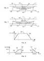
- FIG. 8is a graph of the voltage of a charge cycle of a piezoelectric actuator in accordance with the disclosure.
- FIG. 9is a graph of the voltage across the piezoelectric element 402 for a press and release of the touch-sensitive display in accordance with the disclosure.
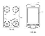
- FIG. 10is a top view of piezoelectric actuators disposed on a base in accordance with the disclosure.
- FIG. 11is a front view of a portable electronic device having a touch-sensitive display in accordance with the disclosure.
- One or more piezoelectric actuatorsmay be utilized to provide tactile feedback to the touch-sensitive display, for example, in response to an actuation signal.
- the piezoelectric actuatorsmay be mechanically preloaded, such that feedback may be provided by moving the touch-sensitive display in either direction with respect to the housing.
- the actuatorsmay be controlled, e.g, via a processor, to provide tactile feedback via the touch-sensitive display, for example, to simulate depression or actuation of a switch, such as switch that may be utilized as part of a physical key of a keyboard, e.g., a dome switch, snap switch, or any other type of switch that may be simulated.
- Other types of tactile feedbackmay also be provided via such control. Such tactile feedback may be provided in response to depression and release of the touch-sensitive display.
- the disclosuregenerally relates to an electronic device, which is a portable electronic device in the embodiments described herein.
- portable electronic devicesinclude mobile, or handheld, wireless communication devices such as pagers, cellular phones, cellular smart-phones, wireless organizers, personal digital assistants, wirelessly enabled notebook computers, and so forth.
- the portable electronic devicemay also be a portable electronic device without wireless communication capabilities, such as a handheld electronic game device, digital photograph album, digital camera, or other device.
- FIG. 1A block diagram of an example of a portable electronic device 100 is shown in FIG. 1 .
- the portable electronic device 100includes multiple components, such as a processor 102 that controls the overall operation of the portable electronic device 100 . Communication functions, including data and voice communications, are performed through a communication subsystem 104 . Data received by the portable electronic device 100 is decompressed and decrypted by a decoder 106 .
- the communication subsystem 104receives messages from and sends messages to a wireless network 150 .
- the wireless network 150may be any type of wireless network, including, but not limited to, data wireless networks, voice wireless networks, and networks that support both voice and data communications.
- a power source 142such as one or more rechargeable batteries or a port to an external power supply, powers the portable electronic device 100 .
- the processor 102interacts with other components, such as Random Access Memory (RAM) 108 , memory 110 , a display 112 with a touch-sensitive overlay 114 operably connected to an electronic controller 116 that together comprise a touch-sensitive display 118 , one or more actuators 120 , one or more force sensors 122 , an auxiliary input/output (I/O) subsystem 124 , a data port 126 , a speaker 128 , a microphone 130 , short-range communications 132 , and other device subsystems 134 .
- User-interaction with a graphical user interfaceis performed through the touch-sensitive overlay 114 .
- the processor 102interacts with the touch-sensitive overlay 114 via the electronic controller 116 .
- Informationsuch as text, characters, symbols, images, icons, and other items that may be displayed or rendered on a portable electronic device, is displayed on the touch-sensitive display 118 via the processor 102 .
- the processor 102may interact with an accelerometer 136 that may be utilized to detect direction of gravitational forces or gravity-induced reaction forces.
- the portable electronic device 100uses a Subscriber Identity Module or a Removable User Identity Module (SIM/RUIM) card 138 for communication with a network, such as the wireless network 150 .
- SIM/RUIMRemovable User Identity Module
- user identification informationmay be programmed into memory 110 .
- the portable electronic device 100includes an operating system 146 and software programs or components 148 that are executed by the processor 102 and are typically stored in a persistent, updatable store such as the memory 110 . Additional applications or programs may be loaded onto the portable electronic device 100 through the wireless network 150 , the auxiliary I/O subsystem 124 , the data port 126 , the short-range communications subsystem 132 , or any other suitable subsystem 134 .
- a received signalsuch as a text message, an e-mail message, or web page download is processed by the communication subsystem 104 and input to the processor 102 .
- the processor 102processes the received signal for output to the display 112 and/or to the auxiliary I/O subsystem 124 .
- a subscribermay generate data items, for example e-mail messages, which may be transmitted over the wireless network 150 through the communication subsystem 104 .
- the speaker 128outputs audible information converted from electrical signals
- the microphone 130converts audible information into electrical signals for processing.
- the touch-sensitive display 118may be any suitable touch-sensitive display, such as a capacitive, resistive, infrared, surface acoustic wave (SAW) touch-sensitive display, strain gauge, optical imaging, dispersive signal technology, acoustic pulse recognition, and so forth, as known in the art.
- a capacitive touch-sensitive displayincludes a capacitive touch-sensitive overlay 114 .
- the overlay 114may be an assembly of multiple layers in a stack including, for example, a substrate, a ground shield layer, a barrier layer, one or more capacitive touch sensor layers separated by a substrate or other barrier, and a cover.
- the capacitive touch sensor layersmay be any suitable material, such as patterned indium tin oxide (ITO).
- One or more touchesmay be detected by the touch-sensitive display 118 .
- the processor 102may determine attributes of the touch, including a location of a touch.
- Touch location datamay include an area of contact or a single point of contact, such as a point at or near a center of the area of contact.
- a signalis provided to the controller 116 in response to detection of a touch.
- a touchmay be detected from any suitable object, such as a finger, thumb, appendage, or other items, for example, a stylus, pen, or other pointer, depending on the nature of the touch-sensitive display 118 .
- the controller 116 and/or the processor 102may detect a touch by any suitable contact member on the touch-sensitive display 118 . Multiple simultaneous touches may be detected.
- the actuator(s) 120may be depressed by applying sufficient force to the touch-sensitive display 118 to overcome the actuation force of the actuator 120 .
- the actuator 120may be actuated by pressing anywhere on the touch-sensitive display 118 .
- the actuator 120may provide input to the processor 102 when actuated. Actuation of the actuator 120 may result in provision of tactile feedback.
- Various different types of actuators 120may be utilized, although only two are described herein. When force is applied, the touch-sensitive display 118 is depressible, pivotable, and/or movable.
- FIG. 2A sectional side view of a portable electronic device 100 with piezoelectric (“piezo”) actuators 120 is shown in FIG. 2 .
- the cross sectionis taken through the centers of the actuators 120 .
- the portable electronic device 100includes a housing 202 that encloses components such as shown in FIG. 1 .
- the housing 202may include a back 204 and a frame 206 that houses the touch-sensitive display 118 .
- Sidewalls 208extend between the back 204 and the frame 206 .
- a base 210extends between the sidewalls 208 , generally parallel to the back 204 , and supports the actuators 120 .
- the display 112 and the overlay 114are supported on a support tray 212 of suitable material, such as magnesium.
- Spacers 216may be located between the support tray 212 and the frame 206 .
- the spacers 216may advantageously be flexible and may also be compliant or compressible, and may comprise gel pads, spring elements such as leaf springs, foam
- the touch-sensitive display 118is movable and depressible with respect to the housing 202 .
- a force 302 applied to the touch-sensitive display 118moves, or depresses, the touch-sensitive display 118 toward the base 210 , and when sufficient force is applied, the actuator 120 is depressed or actuated as shown in FIG. 3 .
- the touch-sensitive display 118may also pivot within the housing to depress the actuator 120 .
- the actuators 120may be actuated by pressing anywhere on the touch-sensitive display 118 .
- the processor 102receives a signal when the actuator 120 is depressed or actuated.
- FIG. 4A sectional side view of a piezo actuator 120 is shown in FIG. 4 .
- the actuator 120may comprise one or more piezo devices or elements 402 .
- the cross-section of FIG. 4is taken through the center of one of the piezo actuators 120 utilized in this example.
- the piezo actuator 120is shown disposed between the base 210 and the touch-sensitive display 118 .
- the piezo actuator 120includes a piezoelectric element 402 , such as a piezoelectric ceramic disk, fastened to a substrate 404 , for example, by adhesive, lamination, laser welding, and/or by other suitable fastening method or device.
- the piezoelectric materialmay be lead zirconate titanate or any other suitable material.
- the piezo element 402is a ceramic disk in this example, the piezoelectric material may have any suitable shape and geometrical features, for example a non-constant thickness, chosen to meet desired specifications.
- the substrate 404which may also be referred to as a shim, may be comprised of a metal such as nickel or any other suitable material such as, for example, stainless steel, brass, and so forth.
- the substrate 404bends when the piezo element 402 contracts diametrically, as a result of build up of charge at the piezo element 402 or in response to a force, such as an external force applied to the touch-sensitive display 118 .
- the substrate 404 and piezo element 402may be suspended or disposed on a support 406 such as a ring-shaped frame for supporting the piezo element 402 while permitting flexing of the piezo actuator 120 as shown in FIG. 4 .
- the supports 406may be disposed on the base 210 or may be part of or integrated with the base 210 , which may be a printed circuit board.
- the substrate 404may rest on the base 210 , and each actuator 120 may be disposed, suspended, or preloaded in an opening in the base 210 .
- the actuator 120is not fastened to the support 406 or the base 210 in these embodiments.
- the actuator 120may optionally be fastened to the support 406 through any suitable method, such as adhesive or other bonding methods.
- a pad 408may be disposed between the piezo actuator 120 and the touch-sensitive display 118 .
- the pad 408 in the present exampleis a compressible element that may provide at least minimal shock-absorbing or buffering protection and may comprise suitable material, such as a hard rubber, silicone, and/or polyester, and/or may comprise other materials such as polycarbonate.
- the pad 408may provide a bumper or cushion for the piezo actuator 120 as well as facilitate actuation of the piezo actuator 120 and/or one or more force sensors 122 that may be disposed between the piezo actuators 120 and the touch-sensitive display 118 .
- the pad 408does not substantially dampen the force applied to or on the touch-sensitive display 118 .
- the pad 408is advantageously aligned with a force sensor 122 .
- the force sensor 122When the touch-sensitive display 118 is depressed, the force sensor 122 generates a force signal that is received and interpreted by the microprocessor 102 .
- the pads 408facilitate the focus of forces exerted on the touch-sensitive display 118 onto the force sensors 122 .
- the pads 408transfer forces between the touch-sensitive display 118 and the actuators 120 , whether the force sensors 122 are above or below the pads 408 .
- the pads 408are advantageously flexible and resilient, and facilitate provision of tactile feedback from the actuators 120 to the touch-sensitive display 118 .
- An optional force sensor 122may be disposed between the piezo actuator 120 and the touch-sensitive display 118 as shown in FIG. 5 .
- the force sensor 122may be disposed between the touch-sensitive display 118 and the pad 408 or between the pad and the piezo actuator 120 , to name a few examples.
- the force sensors 122may be force-sensitive resistors, strain gauges, piezoelectric or piezoresistive devices, pressure sensors, or other suitable devices. Force as utilized throughout the specification, including the claims, refers to force measurements, estimates, and/or calculations, such as pressure, deformation, stress, strain, force density, force-area relationships, thrust, torque, and other effects that include force or related quantities.
- a piezoelectric devicewhich may be the piezo element 402 , may be utilized as a force sensor.
- Force information related to a detected touchmay be utilized to select information, such as information associated with a location of a touch. For example, a touch that does not meet a force threshold may highlight a selection option, whereas a touch that meets a force threshold may select or input that selection option.
- Selection optionsinclude, for example, displayed or virtual keys of a keyboard; selection boxes or windows, e.g., “cancel,” “delete,” or “unlock”; function buttons, such as play or stop on a music player; and so forth.
- Different magnitudes of forcemay be associated with different functions or input. For example, a lesser force may result in panning, and a higher force may result in zooming.
- An optional stop 602may be disposed between the piezo actuator 120 and the base 210 , as shown in FIG. 6 .
- a stop 702may be a coating disposed on the piezo element 402 , such as shown in FIG. 7 .
- the stop 602 , 702provides an endpoint for the travel or movement of the piezo element 402 toward the base 210 .
- the stop 602 , 702and may cushion or buffer the piezo element 402 to distribute the load as the movement of piezo element 402 ends.
- the stop 602 , 702advantageously does not affect the tactile feedback provided by the actuators 120 .
- the stop 602 , 702may be comprised of silicone or any other compressible or compliant material such as polyester, and/or may comprise other materials such as polycarbonate, and so forth.
- the force sensors 122may be operably connected to a controller, which may include an amplifier and analog-to-digital converter, and the piezo actuators 120 may be connected to a piezo driver (not shown) that communicates with the controller, as known in the art.
- the controllermay determine force values for each of the force sensors 122 .
- the controllermay be in communication with the processor 102 or may be part of the processor 102 or controller 116 .
- the controllercontrols the piezo driver that controls the voltage to the piezo elements 402 , and thus controls the charge and the force applied by the piezo actuators 120 on the touch-sensitive display 118 .
- the piezoelectric disks 402may be controlled substantially equally and concurrently, unequally, and/or separately.
- the piezo actuator 120provides tactile feedback for the touch-sensitive display 118 , which tactile feedback simulates the feedback of the depression, or collapse, and release, or return to a rest position, of a mechanical dome switch/actuator, i.e. the piezo actuator 120 provides tactile feedback that simulates the depression and release of a dome switch, for example, based on whether the force of a touch on the touch-sensitive display meets various force thresholds.
- the piezo actuator 120may simulate other types of switches and may provide other types of feedback.
- the piezo elementmay be slightly bent due to a mechanical preload, such as shown in FIG. 2 through FIG. 7 .
- the touch-sensitive display 118compressively stacks the piezo actuator 120 , force sensor 122 (if included), and pad 408 (if included) against the base 210 , resulting in a preload of the piezo actuator 120 .
- the piezo actuator 120may thus be preloaded such that the piezo actuator 120 and the touch-sensitive display 118 are compressively aligned.
- the touch-sensitive display 118is shown in FIG. 2 through FIG. 7 biased toward the piezo actuator 120 to preload the piezo actuator 120 .
- the preloadresults in a bent or curved actuator 120 , as a leaf spring, to facilitate provision of tactile feedback in a direction from the actuator 120 toward the touch-sensitive display 118 and in the opposite direction from the touch-sensitive display 118 toward the actuator 120 , i.e., up and down from the perspective of the drawing or the z-direction, such as indicated by the arrow 302 in FIG. 3 .
- the piezo actuator 120may be preloaded such that the piezo actuator 120 is able to provide tactile feedback by displacing the touch-sensitive display 118 in a direction from the piezo actuator toward the touch-sensitive display 118 .
- tactile feedback to the touch-sensitive display 118may simulate the depression and release of a physical key such as a key of a keyboard or a dome switch.
- the substrate 404 and piezo element 402may be manufactured with a slight curve or pre-warp. When the piezo ceramic 402 is adhered to the substrate 404 with acrylic adhesive, heat may be applied as the acrylic cures, which may result in warping. The preload facilitates mechanical coupling between the piezo actuators 120 and the touch-sensitive display 118 .
- the preload of the actuators 120results in a displacement of the center of actuators 120 in the direction of the base 210 or the bottom or back 204 of the housing 202 , for example, 50 to 100 microns. Any other suitable preload or displacement may be utilized.
- the actuators 120may be further displaced toward the bottom of the housing 202 , e.g., 50 to 100 microns, when the touch-sensitive display 118 is depressed as shown in FIG. 3 , for example, by an applied force that moves or pivots the touch-sensitive display 118 toward the base 210 or the bottom of the housing 202 .
- Contraction of the piezo actuators 120applies a spring-like force, for example, opposing a force externally applied to the touch-sensitive display 118 .
- the substrate 404bends when the piezo element 402 contracts due to build up of charge at the piezo element 402 or in response to a force, such as an external force applied to the touch-sensitive display 118 .
- the chargemay be adjusted by varying the applied voltage or current, thereby controlling the force applied by the piezo element 402 and the resulting movement of the touch-sensitive display.
- the charge on the piezo element 402may be removed by a controlled discharge current that causes the piezo element 402 to expand, releasing the force thereby decreasing the force applied by the piezo element 402 .
- the chargemay advantageously be removed over a relatively short period of time to provide tactile feedback.
- the piezo actuator 120straightens or flattens as it applies force on the touch-sensitive display 118 , and bends more as the touch-sensitive display 118 is depressed.
- the graph shown in FIG. 8illustrates one charge cycle of a piezo actuator 120 with a single charge 802 , plateau 804 , and a single discharge 806 .
- a single charge cyclemay simulate a mechanical switch response, providing tactile feedback.
- the increase in charge 802 and decrease in charge 806are shown as symmetrical in FIG. 8 , the increase and decrease need not be symmetrical.
- FIG. 9illustrates tactile feedback that simulates the depression and release of a dome-type switch, which is a type of key that may be utilized in a keyboard.
- the charge and dischargemay be performed in a manner that the user does not detect the resultant force on the touch-sensitive display 118 , or in a manner intended for a user to detect the resultant force on the touch-sensitive display 118 .
- FIG. 9A graph of voltage across the piezo disk 402 for a press and release of the touch-sensitive display 118 is shown in FIG. 9 .
- This exampleillustrates simulation of a dome-type switch as tactile feedback provided by the piezo actuators 120 .
- the voltage across one of the piezo elements 402 versus timeis shown.
- the voltage across the piezo element 402is related to the charge applied to the piezo element 402 .
- the voltagemay vary, for example, between 0 and 150 V. Presuming a touch event begins at time 0 , the external force exerted on the touch-sensitive display 118 increases, and the touch-sensitive display 118 moves toward the base 210 , resulting in deflection of the piezo actuators 120 , such as shown in FIG. 3 . When the force is below a first threshold, the piezo actuators 120 are not actuated, as shown before point 902 .
- the piezo actuators 120are actuated by applying current to the piezo elements 402 .
- the applied currentmay be ramped up over a period of time, for example, such that the force on the touch-sensitive display 118 and any resulting deflection of the touch-sensitive display 118 is not detectable by the user.
- the external force applied to the touch-sensitive display 118may be about 1.5 N.
- the piezo actuator 120provides an opposing spring-like force, and when actuated, may ramp up to an additional opposing force of about 0.7 N over a period of about 20 milliseconds, for example.
- the curve 904illustrates the increase in voltage across a piezo disk 402 as a result of the applied current to charge the piezo disks 402 .
- the charge on the piezo elements 402is removed by a suitable discharge current from point 906 to point 908 , thereby reducing the voltage across the piezo disks 402 .
- the chargemay be removed over a much shorter period of time than the period of ramp up.
- the additional opposing force of about 0.7 Nmay be reduced to about 0 over a period of about 3 milliseconds between the points 906 and 908 , thereby causing movement of the touch-sensitive display 118 toward the base 210 , simulating collapse of a dome-type switch and providing tactile feedback.
- the force on the touch-sensitive display 118is reduced as the touch-sensitive display 118 is released, e.g., when the user ends the touch event between points 908 and 910 .
- the end of the touch eventis detected as the force sensors 122 detect or measure a force that meets a second force threshold.
- the applied current to the piezo elements 402is increased, for example over a period of about 3 milliseconds, thereby increasing the voltage across the piezo disks 402 , between the points 910 and 912 , increasing the force applied by the piezo actuator 120 on the touch-sensitive display 118 , e.g., to about 0.7 N.
- Movement of the touch-sensitive display 118 away from the base 210results, taking place over a very short period of time when compared to the period of time for ramp down along curve 914 or ramp up along curve 904 .
- the release of a dome-type switchis thus simulated as the provided tactile feedback.
- the charge on the piezo element 402is removed by a discharge current, thereby reducing the voltage across the piezo elements 402 to reduce the additional applied force to about 0 along the curve 914 . This reduction occurs over a much longer period of time relative to the period of time for simulating release of the dome-type switch.
- the discharge currentmay be applied to reduce the voltage across the piezo elements 402 over a ramp down or decay period of about 20 milliseconds, as shown in the downward-sloping segment 914 of the graph of FIG. 9 , thereby removing the force applied by the piezo actuators 120 , for example, over a period of time such that the reduction is not detected by a user.
- the processor 102generates and provides an actuation signal to the actuators 120 to provide tactile feedback to the touch-sensitive display 118 .
- the actuation signalincludes tactile feedback information, such as duration, magnitude or intensity, and frequency of feedback information for the actuators 120 .
- the actuation signalmay be based at least in part on the force or the force signal provided by the force sensors 122 .
- the intensity of the feedbackmay be varied in relation to the amount of the applied force.
- the actuation signalprovides information and/or instructions for how the actuators 120 move the touch-sensitive display 118 .
- the piezo actuators 120move the touch-sensitive display relative to the housing 202 to provide the tactile feedback.
- the piezo actuators 120may move the touch-sensitive display 118 in opposing directions, e.g., in each z direction or up and down from the perspective of FIG. 3 , resulting in vibration of the touch-sensitive display 118 .
- the touch-sensitive display 118may move in an inward direction with respect to the housing 202 , i.e., in a direction toward the base 201 or back 204 of the housing 202 .
- the touch-sensitive display 118may also move in an outward direction with respect to the housing 202 , i.e., in a direction away from the base 201 or back 204 of the housing 202 .
- the provision of tactile feedbackmay result in a single movement of the touch-sensitive display 118 , such as a single pulse or click.
- the tactile feedbackmay comprise, for example, vibrations and pulses or clicks, individually or in combination and may simulate various different perceptible tactile sensations.
- the tactile feedbackis provided to the touch-sensitive display 118 , less intense feedback may be felt along the housing 202 .
- the actuators 120may vibrate the touch-sensitive display 118 in opposing directions, e.g., in the z direction or up and down from the perspective of the drawings.
- the touch-sensitive display 118vibrates while the housing 202 remains relatively stationary, i.e., the housing 202 is not directly vibrated.
- the touch-sensitive display 118may vibrate, for example, at one or more frequencies between 100 and 160 Hz.
- the touch-sensitive display 118may vibrate at multiple frequencies, for example, vibrating at 50 Hz for a tenth of a second and then vibrating at 100 Hz for a tenth of a second.
- the actuators 120may be controlled to vibrate over various or varied distances.
- the actuators 120may be controlled vibrate the touch-sensitive display 118 across a varying frequency sweep, for example, 0 Hz to 150 Hz and back to 0 Hz in three tenths of a second. Vibrations may be provided at other frequencies and across other frequency ranges. Other tactile feedback, such as pulses, clicks, or pops, may be provided by the piezo actuators 120 .
- the actuation signalmay be generated in response to detecting a depression of the touch-sensitive display 118 that meets a force condition, such as a force associated with selection of an option displayed on the touch-sensitive display 118 .
- the actuation signalmay be generated in response to receiving a wireless communication.
- the portable electronic device 100may have a setting that results in a vibration instead of an audible notification when an incoming wireless communication is received.
- the wireless communicationmay be a voice communication, such as a cellular telephone call, or a data communication, such as an email, short messaging service (SMS) message, text message, and so forth.
- SMSshort messaging service
- the actuation signalmay be varied according to the identity of a caller of a voice communication or sender of a data communication, thereby providing a tailored notification.
- the arrangement of piezo actuators 120may thus be utilized to provide tactile feedback instead of a vibrator motor, which may be eliminated from the design of the portable electronic device 100 .
- the piezo actuators 120do not need a significant amount of time to come up to speed or slow down, as do vibrator motors, thus the piezo actuators 120 are able to provide vibration or tactile feedback more quickly than a vibrator motor when instructed to provide feedback.
- tactile feedbackmay be provided in response to detected input from the touch-sensitive display 118 or in response to receiving an outside signal, such as a wireless communication.
- the actuators 120may emulate the feel of a dome switch collapse and subsequent release, which is similar to simulating the press and release of a key of a keyboard.
- tactile feedback simulating the press and release of a keyis provided via the piezo actuators 120 .
- Such feedbacksimulates typing on a keyboard comprised of physical keys.
- Similar or other feedbackmay be provided when a user selects other displayed options, such as decision windows, e.g., a displayed delete or unlock box.
- Feedbackmay be provided during the operation of a camera of a portable electronic device 100 .
- depression of the touch-sensitive display 118may act as a shutter to take and record a digital picture, and the feedback may simulate the feel of a shutter press and release.
- Other physical switchesmay be simulated through tactile feedback provided by the piezo actuators 120 .
- FIG. 10A top view of piezo actuators 120 disposed on a base 210 is shown in FIG. 10 .
- the base 210may advantageously be a printed circuit board or other suitable structure.
- Four supports 406 and a piezo actuator 120is disposed in each support 406 .
- Other electronic and or mechanical componentsmay be disposed on the base 210 .
- a force sensor 122is shown disposed on each actuator 120 .
- Conductors(not shown) may be disposed on the base 210 to electrically connect each piezo actuator 120 and each force sensor 122 to the processor 102 .
- a pad 408is shown disposed with respect to each force sensor 120 .
- four actuators 120are utilized, one disposed near each corner of the base 210 or near each corner of the touch-sensitive display 118 .
- any suitable size of the force sensor 122 , piezo element 402 , the substrate 404 , the pad 408 , and/or the stop 602 , 702may be utilized.
- the relative sizes of these devices 122 , 402 , 404 , 408 , 602 , 702may be chosen to facilitate the response and feedback desired, as well as to fit within the available space.
- the force sensor 122 , piezo element 402 , the substrate 404 , the pad 408 , and/or the stop 602 , 702are shown advantageously centered with respect to each other. Such an alignment is advantageous because the center of the piezo element 402 has the largest potential displacement distance in the z direction. Nevertheless, other alignments of the force sensor 122 and the pad 408 that are not near or around the central area of the piezo actuator 120 may be successfully implemented. Other arrangements and organizations of these devices 122 , 402 , 404 , 408 , 602 , 702 may also be successful, including different orders. Each pad 408 may be optionally fastened to the force sensor 122 , the substrate 404 , the base 210 or any combination thereof. Each force sensor 122 may be optionally fastened to the pad 408 , the substrate 404 , the base 210 , or any combination thereof. An adhesive, lamination, or other suitable measures/processes may be utilized as a fastening mechanism.
- FIG. 11A front view of a portable electronic device 100 having a touch-sensitive display 118 is shown in FIG. 11 .
- a housing 202 , the speaker 128 , and various physical buttons or keys 204are also shown.
- the keys 204are shown separate from the touch-sensitive display, the keys 1102 may alternatively be soft or virtual keys displayed on the touch-sensitive display 118 .
- the present disclosuremay be applied to other touch-sensitive input devices, such as touch pads with tactile feedback.
- Feedback loops resulting from the triggering of the actuators 120 due to forces applied by the actuators 120may be addressed in software, for example, by any combination of time delays, force thresholds conditions, and so forth.
- the methods described hereinmay be carried out by software executed, for example, by the processor 102 . Coding of software for carrying out such a method is within the scope of a person of ordinary skill in the art given the present description.
- a computer-readable medium having computer-readable codemay be executed by at least one processor of the portable electronic device 100 to perform the methods described herein.
- Portable electronic devices utilizing piezo actuators as describedare able to provide a user with versatile tactile feedback.
- the piezo actuatorswhen suspended as described herein, are able to provide tactile feedback, including vibration instead of a vibrator motor, by moving a depressible/movable touch-sensitive display in an upward and/or downward direction, or away from or toward the back of the housing of the portable electronic device.
- the actuatorsmay be controlled to move the touch-sensitive display upward and downward at almost any time.
- Tactile feedbackmay be provided in response to multiple touches in rapid succession. Force information related to a detected touch may be utilized to select information as well as to provide the capability of associating different magnitudes of force with different functions or input.
- the piezo actuator arrangements described hereinmay be applied to devices other than portable electronic devices to provide tactile feedback, including devices without touch-sensitive displays.
- a portable electronic devicecomprises a touch-sensitive display and a piezoelectric actuator disposed and preloaded on a support and arranged to provide tactile feedback to the touch-sensitive display in response to an actuation signal.
- the portable electronic devicemay comprise a touch-sensitive display and a piezoelectric actuator arranged to provide tactile feedback to the touch-sensitive display in response to an actuation signal, wherein the touch-sensitive display is biased toward the piezoelectric actuator to preload the piezoelectric actuator.
- the portable electronic devicemay comprise a housing; a touch-sensitive display movable with respect to the housing; a piezoelectric actuator preloaded between the housing and the touch-sensitive display; a force sensor arranged such that depression of the touch-sensitive display causes the force sensor to generate a force signal; and a processor configured to receive the force signal and to provide an actuation signal to the piezoelectric actuator, which actuation signal causes the piezoelectric actuator to provide tactile feedback to the touch-sensitive display.
- the piezoelectric actuatormay be preloaded such that the piezoelectric actuator and the touch-sensitive display are compressively aligned.
- the touch-sensitive displaymay be biased toward the piezoelectric actuator to preload the piezoelectric actuator.
- the piezoelectric actuatormay be preloaded such that the piezoelectric actuator provides tactile feedback by displacing the touch-sensitive display in a direction from the piezoelectric actuator toward the touch-sensitive display.
- the piezoelectric actuatormay be preloaded such that the piezoelectric actuator provides tactile feedback by displacing the touch-sensitive display in a direction from the touch-sensitive display toward the piezoelectric actuator.
- the touch-sensitive displaymay be depressible or movable with respect to a housing of the portable electronic device.
- the devicemay comprise a processor configured to generate an actuation signal.
- the devicemay comprise a force sensor disposed between the piezoelectric actuator and the touch-sensitive display.
- the force sensormay be a force-sensitive resistor.
- the devicemay comprise a pad disposed between the piezoelectric actuator and the touch-sensitive display.
- the devicemay comprise a stop disposed between the piezoelectric actuator and a base on which the support is disposed.
- the devicemay comprise a stop disposed on the piezoelectric actuator.
- the devicemay comprise a stop disposed between the piezoelectric actuator and a housing of the portable electronic device, wherein the stop is disposed such that the stop does not interfere with the provision tactile feedback.
- a portable electronic devicecomprises a housing, a touch-sensitive display movable with respect to the housing, and at least one piezoelectric actuator arranged to provide tactile feedback to the touch-sensitive display in response to an actuation signal by moving the touch-sensitive display.
- the at least one piezoelectric actuatormay move the touch-sensitive display in opposing directions, which may result in vibration of the touch-sensitive display.
- the provision of tactile feedbackmay result in a single movement of the touch-sensitive display.
- the touch-sensitive displaymay move in an inward direction with respect to the housing.
- the touch-sensitive displaymay move in an outward direction with respect to the housing.
- the devicemay comprise a processor configured to generate the actuation signal.
- the devicemay comprise a force sensor disposed between the piezoelectric actuator and the touch-sensitive display.
- the devicemay comprise a force sensor, wherein the force sensor is arranged such that depression of the touch-sensitive display causes the force sensor to generate a force signal.
- the devicemay comprise a processor configured to generate the actuation signal based at least in part on the force signal.
- the actuation signalmay comprise at least one of duration, magnitude or intensity, and frequency of the tactile feedback.
- the touch-sensitive displaymay be biased toward the at least one piezoelectric actuator to preload the at least one piezoelectric actuator.
- a methodcomprises generating an actuation signal that includes tactile feedback information and providing tactile feedback to a touch-sensitive display in response to the actuation signal, wherein at least one piezoelectric actuator moves the touch-sensitive display relative to a housing to provide the tactile feedback.
- the provision of tactile feedbackmay result in vibration of the touch-sensitive display.
- the provision of tactile feedbackmay result in a single movement of the touch-sensitive display.
- the touch-sensitive displaymay move in an inward direction with respect to the housing.
- the touch-sensitive displaymay move in an outward direction with respect to the housing.
- the methodmay comprise generating the actuation signal based at least in part on a force signal.
- the actuation signalmay comprise at least one of duration, magnitude or intensity, and frequency of the tactile feedback.
- a force sensormay be arranged such that depression of the touch-sensitive display causes the force sensor to generate a force signal.
- the actuation signalmay be generated in response to detecting a depression of the touch-sensitive display that meets a force condition.
- the actuation signalmay be generated in response to receiving a wireless communication.
Landscapes
- Engineering & Computer Science (AREA)
- General Engineering & Computer Science (AREA)
- Theoretical Computer Science (AREA)
- Human Computer Interaction (AREA)
- Physics & Mathematics (AREA)
- General Physics & Mathematics (AREA)
- Computer Hardware Design (AREA)
- User Interface Of Digital Computer (AREA)
Abstract
Description
Claims (17)
Priority Applications (1)
| Application Number | Priority Date | Filing Date | Title |
|---|---|---|---|
| US12/578,246US8384680B2 (en) | 2008-12-23 | 2009-10-13 | Portable electronic device and method of control |
Applications Claiming Priority (2)
| Application Number | Priority Date | Filing Date | Title |
|---|---|---|---|
| US12/342,502US20100156814A1 (en) | 2008-12-23 | 2008-12-23 | Portable electronic device including tactile touch-sensitive input device and method of controlling same |
| US12/578,246US8384680B2 (en) | 2008-12-23 | 2009-10-13 | Portable electronic device and method of control |
Related Parent Applications (1)
| Application Number | Title | Priority Date | Filing Date |
|---|---|---|---|
| US12/342,502Continuation-In-PartUS20100156814A1 (en) | 2008-12-23 | 2008-12-23 | Portable electronic device including tactile touch-sensitive input device and method of controlling same |
Publications (2)
| Publication Number | Publication Date |
|---|---|
| US20100156824A1 US20100156824A1 (en) | 2010-06-24 |
| US8384680B2true US8384680B2 (en) | 2013-02-26 |
Family
ID=42265297
Family Applications (1)
| Application Number | Title | Priority Date | Filing Date |
|---|---|---|---|
| US12/578,246Active2030-05-03US8384680B2 (en) | 2008-12-23 | 2009-10-13 | Portable electronic device and method of control |
Country Status (1)
| Country | Link |
|---|---|
| US (1) | US8384680B2 (en) |
Cited By (36)
| Publication number | Priority date | Publication date | Assignee | Title |
|---|---|---|---|---|
| US8547339B2 (en) | 2008-01-04 | 2013-10-01 | Tactus Technology, Inc. | System and methods for raised touch screens |
| US8553005B2 (en) | 2008-01-04 | 2013-10-08 | Tactus Technology, Inc. | User interface system |
| US8570295B2 (en) | 2008-01-04 | 2013-10-29 | Tactus Technology, Inc. | User interface system |
| US8587548B2 (en) | 2009-07-03 | 2013-11-19 | Tactus Technology, Inc. | Method for adjusting the user interface of a device |
| US8619035B2 (en) | 2010-02-10 | 2013-12-31 | Tactus Technology, Inc. | Method for assisting user input to a device |
| US8922502B2 (en) | 2008-01-04 | 2014-12-30 | Tactus Technology, Inc. | User interface system |
| US8922510B2 (en) | 2008-01-04 | 2014-12-30 | Tactus Technology, Inc. | User interface system |
| US8922503B2 (en) | 2008-01-04 | 2014-12-30 | Tactus Technology, Inc. | User interface system |
| US8928621B2 (en) | 2008-01-04 | 2015-01-06 | Tactus Technology, Inc. | User interface system and method |
| US8947383B2 (en) | 2008-01-04 | 2015-02-03 | Tactus Technology, Inc. | User interface system and method |
| US8970403B2 (en) | 2008-01-04 | 2015-03-03 | Tactus Technology, Inc. | Method for actuating a tactile interface layer |
| US9019228B2 (en) | 2008-01-04 | 2015-04-28 | Tactus Technology, Inc. | User interface system |
| US9052790B2 (en) | 2008-01-04 | 2015-06-09 | Tactus Technology, Inc. | User interface and methods |
| US9063627B2 (en) | 2008-01-04 | 2015-06-23 | Tactus Technology, Inc. | User interface and methods |
| US9075525B2 (en) | 2008-01-04 | 2015-07-07 | Tactus Technology, Inc. | User interface system |
| US9098141B2 (en) | 2008-01-04 | 2015-08-04 | Tactus Technology, Inc. | User interface system |
| US9116617B2 (en) | 2009-07-03 | 2015-08-25 | Tactus Technology, Inc. | User interface enhancement system |
| US9170652B2 (en) | 2010-11-12 | 2015-10-27 | Kyocera Corporation | Electronic device and portable terminal provided with same |
| US9239623B2 (en) | 2010-01-05 | 2016-01-19 | Tactus Technology, Inc. | Dynamic tactile interface |
| US9274612B2 (en) | 2008-01-04 | 2016-03-01 | Tactus Technology, Inc. | User interface system |
| US9280224B2 (en) | 2012-09-24 | 2016-03-08 | Tactus Technology, Inc. | Dynamic tactile interface and methods |
| US9298261B2 (en) | 2008-01-04 | 2016-03-29 | Tactus Technology, Inc. | Method for actuating a tactile interface layer |
| US9372565B2 (en) | 2008-01-04 | 2016-06-21 | Tactus Technology, Inc. | Dynamic tactile interface |
| US9405417B2 (en) | 2012-09-24 | 2016-08-02 | Tactus Technology, Inc. | Dynamic tactile interface and methods |
| US9423875B2 (en) | 2008-01-04 | 2016-08-23 | Tactus Technology, Inc. | Dynamic tactile interface with exhibiting optical dispersion characteristics |
| US9477308B2 (en) | 2008-01-04 | 2016-10-25 | Tactus Technology, Inc. | User interface system |
| US9552065B2 (en) | 2008-01-04 | 2017-01-24 | Tactus Technology, Inc. | Dynamic tactile interface |
| US9557915B2 (en) | 2008-01-04 | 2017-01-31 | Tactus Technology, Inc. | Dynamic tactile interface |
| US9557813B2 (en) | 2013-06-28 | 2017-01-31 | Tactus Technology, Inc. | Method for reducing perceived optical distortion |
| US9588683B2 (en) | 2008-01-04 | 2017-03-07 | Tactus Technology, Inc. | Dynamic tactile interface |
| US9588684B2 (en) | 2009-01-05 | 2017-03-07 | Tactus Technology, Inc. | Tactile interface for a computing device |
| US9612659B2 (en) | 2008-01-04 | 2017-04-04 | Tactus Technology, Inc. | User interface system |
| US9720501B2 (en) | 2008-01-04 | 2017-08-01 | Tactus Technology, Inc. | Dynamic tactile interface |
| US9760172B2 (en) | 2008-01-04 | 2017-09-12 | Tactus Technology, Inc. | Dynamic tactile interface |
| US9898087B2 (en) | 2013-10-08 | 2018-02-20 | Tk Holdings Inc. | Force-based touch interface with integrated multi-sensory feedback |
| US20240329765A1 (en)* | 2023-03-27 | 2024-10-03 | Cirque Corporation | Pressure Capacitive Reference Fixed to a Housing |
Families Citing this family (26)
| Publication number | Priority date | Publication date | Assignee | Title |
|---|---|---|---|---|
| US8814686B2 (en) | 2010-02-03 | 2014-08-26 | Nintendo Co., Ltd. | Display device, game system, and game method |
| US8339364B2 (en) | 2010-02-03 | 2012-12-25 | Nintendo Co., Ltd. | Spatially-correlated multi-display human-machine interface |
| US8913009B2 (en) | 2010-02-03 | 2014-12-16 | Nintendo Co., Ltd. | Spatially-correlated multi-display human-machine interface |
| KR101154636B1 (en)* | 2010-02-03 | 2012-06-08 | 닌텐도가부시키가이샤 | Display device, game system, and game method |
| USD629782S1 (en)* | 2010-02-19 | 2010-12-28 | Samsung Electronics Co., Ltd. | Mobile phone |
| KR101164861B1 (en)* | 2010-06-29 | 2012-07-18 | 주식회사 에프나인 | Touch screen with vibrating function |
| US9110536B2 (en)* | 2010-07-05 | 2015-08-18 | Nokia Technologies Oy | Apparatus and a method for providing haptic feedback |
| JP6243586B2 (en) | 2010-08-06 | 2017-12-06 | 任天堂株式会社 | GAME SYSTEM, GAME DEVICE, GAME PROGRAM, AND GAME PROCESSING METHOD |
| US10150033B2 (en) | 2010-08-20 | 2018-12-11 | Nintendo Co., Ltd. | Position calculation system, position calculation device, storage medium storing position calculation program, and position calculation method |
| US10645834B2 (en)* | 2010-08-23 | 2020-05-05 | Nokia Technologies Oy | Apparatus and method for providing haptic and audio feedback in a touch sensitive user interface |
| JP5840386B2 (en) | 2010-08-30 | 2016-01-06 | 任天堂株式会社 | GAME SYSTEM, GAME DEVICE, GAME PROGRAM, AND GAME PROCESSING METHOD |
| JP5840385B2 (en) | 2010-08-30 | 2016-01-06 | 任天堂株式会社 | GAME SYSTEM, GAME DEVICE, GAME PROGRAM, AND GAME PROCESSING METHOD |
| US10638617B2 (en) | 2010-10-19 | 2020-04-28 | Nokia Technologies Oy | Display apparatus |
| TWI440496B (en)* | 2010-11-01 | 2014-06-11 | Nintendo Co Ltd | Controller device and controller system |
| KR101364826B1 (en) | 2010-11-01 | 2014-02-20 | 닌텐도가부시키가이샤 | Operating apparatus and operating system |
| JP5689014B2 (en) | 2011-04-07 | 2015-03-25 | 任天堂株式会社 | Input system, information processing apparatus, information processing program, and three-dimensional position calculation method |
| US20120327014A1 (en)* | 2011-06-24 | 2012-12-27 | Research In Motion Limited | Touch-sensitive display and electronic device including same |
| US8737062B2 (en)* | 2011-11-22 | 2014-05-27 | Htc Corporation | Handheld electronic device |
| US8837143B2 (en)* | 2011-11-25 | 2014-09-16 | Htc Corporation | Handheld electronic device |
| US11474645B2 (en)* | 2012-03-27 | 2022-10-18 | Nokia Technologies Oy | Method and apparatus for force sensing |
| WO2014024011A1 (en) | 2012-08-10 | 2014-02-13 | Nokia Corporation | A display apparatus providing tactile functionality |
| US20140075379A1 (en)* | 2012-09-11 | 2014-03-13 | Erich Schlaepfer | Direct character display control |
| US9715300B2 (en)* | 2013-03-04 | 2017-07-25 | Microsoft Technology Licensing, Llc | Touch screen interaction using dynamic haptic feedback |
| TWI578359B (en)* | 2013-07-24 | 2017-04-11 | 達方電子股份有限公司 | Button, keyboard and force feedback method |
| DE102014000829B4 (en) | 2014-01-21 | 2019-02-28 | Harald Kobolla | Portable computer with a haptic output device |
| KR102255710B1 (en)* | 2014-10-07 | 2021-05-26 | 엘지전자 주식회사 | Mobile terminal |
Citations (28)
| Publication number | Priority date | Publication date | Assignee | Title |
|---|---|---|---|---|
| JPH09173979A (en) | 1995-12-28 | 1997-07-08 | Sony Corp | Vibration mechanism of piezoelectric type and portable telephone set using the same |
| JPH09507315A (en) | 1993-12-15 | 1997-07-22 | インターリンク エレクトロニクス インコーポレイテッド | Force sensing pointing device |
| JPH10105243A (en) | 1996-09-10 | 1998-04-24 | Hewlett Packard Co <Hp> | Positioning feature, positioning device and information recorder |
| JPH11212725A (en) | 1998-01-26 | 1999-08-06 | Idec Izumi Corp | Information display device and operation input device |
| WO2001054109A1 (en) | 2000-01-19 | 2001-07-26 | Immersion Corporation | Haptic feedback for touchpads and other touch controls |
| US6359758B1 (en) | 1998-06-11 | 2002-03-19 | Seagate Technology, Llc | Rigid body microactuator having elastic joint attachment |
| EP1310860A1 (en) | 2000-08-08 | 2003-05-14 | NTT DoCoMo, Inc. | Electronic apparatus, vibration generator, vibratory informing method and method for controlling information |
| US20040070314A1 (en) | 2001-11-28 | 2004-04-15 | Yoon Kwang Joon | Curved shape actuator device composed of electro active layer and fiber composite layers |
| US6744577B1 (en) | 2001-03-23 | 2004-06-01 | Maxtor Corporation | Piezoelectric actuator and shock sensor |
| CA2518914A1 (en) | 2003-03-14 | 2004-09-23 | Handshake Vr Inc. | A method and system for providing haptic effects |
| US6822635B2 (en) | 2000-01-19 | 2004-11-23 | Immersion Corporation | Haptic interface for laptop computers and other portable devices |
| US20050057528A1 (en) | 2003-09-01 | 2005-03-17 | Martin Kleen | Screen having a touch-sensitive user interface for command input |
| JP2005149197A (en) | 2003-11-17 | 2005-06-09 | Sony Corp | Input device, information processor, remote controller and method of controlling input device |
| US20050277448A1 (en) | 2004-06-10 | 2005-12-15 | Motorola, Inc. | Soft buttons on LCD module with tactile feedback |
| US20060050059A1 (en)* | 2002-12-12 | 2006-03-09 | Kimiyasu Satoh | Input device, portable electronic apparatus, remote control device, and piezoelectric actuator driving controlling method in input device |
| WO2006042309A1 (en) | 2004-10-08 | 2006-04-20 | Immersion Corporation | Haptic feedback for button and scrolling action simulation in touch input devices |
| JP2006107140A (en) | 2004-10-05 | 2006-04-20 | Sony Corp | Input/output device with tactile function, and electronic device |
| EP1691263A1 (en) | 2005-02-11 | 2006-08-16 | Apple Computer, Inc. | Display actuator |
| US20060209037A1 (en) | 2004-03-15 | 2006-09-21 | David Wang | Method and system for providing haptic effects |
| US20070015297A1 (en) | 2002-11-27 | 2007-01-18 | Lsi Logic Corporation | Failure analysis vehicle for yield enhancement with self test at speed burnin capability for reliability testing |
| EP1748350A2 (en) | 2005-07-28 | 2007-01-31 | Avago Technologies General IP (Singapore) Pte. Ltd | Touch device and method for providing tactile feedback |
| US20070080951A1 (en) | 2002-08-29 | 2007-04-12 | Sony Corporation | Input device and electronic device using the input device |
| US7205978B2 (en) | 2002-01-28 | 2007-04-17 | Sony Corporation | Mobile apparatus having tactile feedback function |
| US20070103449A1 (en) | 2005-11-08 | 2007-05-10 | Nokia Corporation | Cost efficient element for combined piezo sensor and actuator in robust and small touch screen realization and method for operation thereof |
| US20080013231A1 (en) | 2006-07-13 | 2008-01-17 | Stmicroelectronics S.R.L. | Esd protection circuit |
| US20080024459A1 (en)* | 2006-07-31 | 2008-01-31 | Sony Corporation | Apparatus and method for touch screen interaction based on tactile feedback and pressure measurement |
| US20080055277A1 (en)* | 2006-08-29 | 2008-03-06 | Sony Corporation | Touch panel display, electronic apparatus and playing apparatus |
| JP2008123453A (en) | 2006-11-15 | 2008-05-29 | Sony Corp | Substrate support vibration structure, input device with tactile function, and electronic device |
- 2009
- 2009-10-13USUS12/578,246patent/US8384680B2/enactiveActive
Patent Citations (37)
| Publication number | Priority date | Publication date | Assignee | Title |
|---|---|---|---|---|
| JPH09507315A (en) | 1993-12-15 | 1997-07-22 | インターリンク エレクトロニクス インコーポレイテッド | Force sensing pointing device |
| JPH09173979A (en) | 1995-12-28 | 1997-07-08 | Sony Corp | Vibration mechanism of piezoelectric type and portable telephone set using the same |
| JPH10105243A (en) | 1996-09-10 | 1998-04-24 | Hewlett Packard Co <Hp> | Positioning feature, positioning device and information recorder |
| JPH11212725A (en) | 1998-01-26 | 1999-08-06 | Idec Izumi Corp | Information display device and operation input device |
| US6359758B1 (en) | 1998-06-11 | 2002-03-19 | Seagate Technology, Llc | Rigid body microactuator having elastic joint attachment |
| US6429846B2 (en) | 1998-06-23 | 2002-08-06 | Immersion Corporation | Haptic feedback for touchpads and other touch controls |
| US20080068348A1 (en) | 1998-06-23 | 2008-03-20 | Immersion Corporation | Haptic feedback for touchpads and other touch controls |
| US7548232B2 (en) | 2000-01-19 | 2009-06-16 | Immersion Corporation | Haptic interface for laptop computers and other portable devices |
| US20080060856A1 (en) | 2000-01-19 | 2008-03-13 | Immersion Corporation | Haptic interface for touch screen embodiments |
| US6822635B2 (en) | 2000-01-19 | 2004-11-23 | Immersion Corporation | Haptic interface for laptop computers and other portable devices |
| US7450110B2 (en) | 2000-01-19 | 2008-11-11 | Immersion Corporation | Haptic input devices |
| WO2001054109A1 (en) | 2000-01-19 | 2001-07-26 | Immersion Corporation | Haptic feedback for touchpads and other touch controls |
| EP1310860A1 (en) | 2000-08-08 | 2003-05-14 | NTT DoCoMo, Inc. | Electronic apparatus, vibration generator, vibratory informing method and method for controlling information |
| US6744577B1 (en) | 2001-03-23 | 2004-06-01 | Maxtor Corporation | Piezoelectric actuator and shock sensor |
| US20040070314A1 (en) | 2001-11-28 | 2004-04-15 | Yoon Kwang Joon | Curved shape actuator device composed of electro active layer and fiber composite layers |
| US7205978B2 (en) | 2002-01-28 | 2007-04-17 | Sony Corporation | Mobile apparatus having tactile feedback function |
| US20070080951A1 (en) | 2002-08-29 | 2007-04-12 | Sony Corporation | Input device and electronic device using the input device |
| US20070015297A1 (en) | 2002-11-27 | 2007-01-18 | Lsi Logic Corporation | Failure analysis vehicle for yield enhancement with self test at speed burnin capability for reliability testing |
| US20060050059A1 (en)* | 2002-12-12 | 2006-03-09 | Kimiyasu Satoh | Input device, portable electronic apparatus, remote control device, and piezoelectric actuator driving controlling method in input device |
| CA2518914A1 (en) | 2003-03-14 | 2004-09-23 | Handshake Vr Inc. | A method and system for providing haptic effects |
| US20050057528A1 (en) | 2003-09-01 | 2005-03-17 | Martin Kleen | Screen having a touch-sensitive user interface for command input |
| JP2005149197A (en) | 2003-11-17 | 2005-06-09 | Sony Corp | Input device, information processor, remote controller and method of controlling input device |
| US20060209037A1 (en) | 2004-03-15 | 2006-09-21 | David Wang | Method and system for providing haptic effects |
| US20050277448A1 (en) | 2004-06-10 | 2005-12-15 | Motorola, Inc. | Soft buttons on LCD module with tactile feedback |
| JP2006107140A (en) | 2004-10-05 | 2006-04-20 | Sony Corp | Input/output device with tactile function, and electronic device |
| US20060119586A1 (en) | 2004-10-08 | 2006-06-08 | Immersion Corporation, A Delaware Corporation | Haptic feedback for button and scrolling action simulation in touch input devices |
| JP2008516348A (en) | 2004-10-08 | 2008-05-15 | イマージョン コーポレーション | Haptic feedback for simulating buttons and scrolling motion on touch input devices |
| WO2006042309A1 (en) | 2004-10-08 | 2006-04-20 | Immersion Corporation | Haptic feedback for button and scrolling action simulation in touch input devices |
| EP1691263A1 (en) | 2005-02-11 | 2006-08-16 | Apple Computer, Inc. | Display actuator |
| EP1748350A2 (en) | 2005-07-28 | 2007-01-31 | Avago Technologies General IP (Singapore) Pte. Ltd | Touch device and method for providing tactile feedback |
| US20070103449A1 (en) | 2005-11-08 | 2007-05-10 | Nokia Corporation | Cost efficient element for combined piezo sensor and actuator in robust and small touch screen realization and method for operation thereof |
| US20080013231A1 (en) | 2006-07-13 | 2008-01-17 | Stmicroelectronics S.R.L. | Esd protection circuit |
| US20080024459A1 (en)* | 2006-07-31 | 2008-01-31 | Sony Corporation | Apparatus and method for touch screen interaction based on tactile feedback and pressure measurement |
| US20080055277A1 (en)* | 2006-08-29 | 2008-03-06 | Sony Corporation | Touch panel display, electronic apparatus and playing apparatus |
| JP2008059027A (en) | 2006-08-29 | 2008-03-13 | Sony Corp | Touch panel display device, electronic equipment and game apparatus |
| JP2008123453A (en) | 2006-11-15 | 2008-05-29 | Sony Corp | Substrate support vibration structure, input device with tactile function, and electronic device |
| US20080122315A1 (en) | 2006-11-15 | 2008-05-29 | Sony Corporation | Substrate supporting vibration structure, input device having haptic function, and electronic device |
Non-Patent Citations (8)
| Title |
|---|
| "Interview RIM" from EPO Examiner on Mar. 19, 2012. |
| Chinese Office Action dated Jun. 6, 2012, from corresponding CN patent application 200910262274.7, 12 pages. |
| Extended European Search Report for European Application No. 09172936.8, dated Feb. 4, 2010, 7 pages. |
| Extended European Search Report for European Application No. 09172937.6, dated Feb. 10, 2010, 6 pages. |
| Extended European Search Report for European Application No. 09172940.0. dated Feb. 11, 2010, 6 pages. |
| Extended European Search Report for European Application No. 09173502.7, dated Feb. 23, 2010, 6 pages. |
| Office Action dated Feb. 17, 2012, issued from corresponding CA patent application No. 2688113. |
| Office Action dated Jan. 11, 2012, issued from corresponding JP patent application No. 2009-279907. |
Cited By (51)
| Publication number | Priority date | Publication date | Assignee | Title |
|---|---|---|---|---|
| US9552065B2 (en) | 2008-01-04 | 2017-01-24 | Tactus Technology, Inc. | Dynamic tactile interface |
| US9720501B2 (en) | 2008-01-04 | 2017-08-01 | Tactus Technology, Inc. | Dynamic tactile interface |
| US8570295B2 (en) | 2008-01-04 | 2013-10-29 | Tactus Technology, Inc. | User interface system |
| US9760172B2 (en) | 2008-01-04 | 2017-09-12 | Tactus Technology, Inc. | Dynamic tactile interface |
| US9626059B2 (en) | 2008-01-04 | 2017-04-18 | Tactus Technology, Inc. | User interface system |
| US8717326B2 (en) | 2008-01-04 | 2014-05-06 | Tactus Technology, Inc. | System and methods for raised touch screens |
| US8922502B2 (en) | 2008-01-04 | 2014-12-30 | Tactus Technology, Inc. | User interface system |
| US8922510B2 (en) | 2008-01-04 | 2014-12-30 | Tactus Technology, Inc. | User interface system |
| US8922503B2 (en) | 2008-01-04 | 2014-12-30 | Tactus Technology, Inc. | User interface system |
| US8928621B2 (en) | 2008-01-04 | 2015-01-06 | Tactus Technology, Inc. | User interface system and method |
| US8947383B2 (en) | 2008-01-04 | 2015-02-03 | Tactus Technology, Inc. | User interface system and method |
| US8970403B2 (en) | 2008-01-04 | 2015-03-03 | Tactus Technology, Inc. | Method for actuating a tactile interface layer |
| US9019228B2 (en) | 2008-01-04 | 2015-04-28 | Tactus Technology, Inc. | User interface system |
| US9035898B2 (en) | 2008-01-04 | 2015-05-19 | Tactus Technology, Inc. | System and methods for raised touch screens |
| US9052790B2 (en) | 2008-01-04 | 2015-06-09 | Tactus Technology, Inc. | User interface and methods |
| US9063627B2 (en) | 2008-01-04 | 2015-06-23 | Tactus Technology, Inc. | User interface and methods |
| US9075525B2 (en) | 2008-01-04 | 2015-07-07 | Tactus Technology, Inc. | User interface system |
| US9098141B2 (en) | 2008-01-04 | 2015-08-04 | Tactus Technology, Inc. | User interface system |
| US9619030B2 (en) | 2008-01-04 | 2017-04-11 | Tactus Technology, Inc. | User interface system and method |
| US9612659B2 (en) | 2008-01-04 | 2017-04-04 | Tactus Technology, Inc. | User interface system |
| US9207795B2 (en) | 2008-01-04 | 2015-12-08 | Tactus Technology, Inc. | User interface system |
| US9229571B2 (en) | 2008-01-04 | 2016-01-05 | Tactus Technology, Inc. | Method for adjusting the user interface of a device |
| US9588683B2 (en) | 2008-01-04 | 2017-03-07 | Tactus Technology, Inc. | Dynamic tactile interface |
| US9274612B2 (en) | 2008-01-04 | 2016-03-01 | Tactus Technology, Inc. | User interface system |
| US8553005B2 (en) | 2008-01-04 | 2013-10-08 | Tactus Technology, Inc. | User interface system |
| US9557915B2 (en) | 2008-01-04 | 2017-01-31 | Tactus Technology, Inc. | Dynamic tactile interface |
| US9524025B2 (en) | 2008-01-04 | 2016-12-20 | Tactus Technology, Inc. | User interface system and method |
| US9372539B2 (en) | 2008-01-04 | 2016-06-21 | Tactus Technology, Inc. | Method for actuating a tactile interface layer |
| US9372565B2 (en) | 2008-01-04 | 2016-06-21 | Tactus Technology, Inc. | Dynamic tactile interface |
| US8547339B2 (en) | 2008-01-04 | 2013-10-01 | Tactus Technology, Inc. | System and methods for raised touch screens |
| US9423875B2 (en) | 2008-01-04 | 2016-08-23 | Tactus Technology, Inc. | Dynamic tactile interface with exhibiting optical dispersion characteristics |
| US9430074B2 (en) | 2008-01-04 | 2016-08-30 | Tactus Technology, Inc. | Dynamic tactile interface |
| US9448630B2 (en) | 2008-01-04 | 2016-09-20 | Tactus Technology, Inc. | Method for actuating a tactile interface layer |
| US9477308B2 (en) | 2008-01-04 | 2016-10-25 | Tactus Technology, Inc. | User interface system |
| US9495055B2 (en) | 2008-01-04 | 2016-11-15 | Tactus Technology, Inc. | User interface and methods |
| US9298261B2 (en) | 2008-01-04 | 2016-03-29 | Tactus Technology, Inc. | Method for actuating a tactile interface layer |
| US9588684B2 (en) | 2009-01-05 | 2017-03-07 | Tactus Technology, Inc. | Tactile interface for a computing device |
| US8587548B2 (en) | 2009-07-03 | 2013-11-19 | Tactus Technology, Inc. | Method for adjusting the user interface of a device |
| US9116617B2 (en) | 2009-07-03 | 2015-08-25 | Tactus Technology, Inc. | User interface enhancement system |
| US9239623B2 (en) | 2010-01-05 | 2016-01-19 | Tactus Technology, Inc. | Dynamic tactile interface |
| US9298262B2 (en) | 2010-01-05 | 2016-03-29 | Tactus Technology, Inc. | Dynamic tactile interface |
| US8619035B2 (en) | 2010-02-10 | 2013-12-31 | Tactus Technology, Inc. | Method for assisting user input to a device |
| US9170652B2 (en) | 2010-11-12 | 2015-10-27 | Kyocera Corporation | Electronic device and portable terminal provided with same |
| US9405417B2 (en) | 2012-09-24 | 2016-08-02 | Tactus Technology, Inc. | Dynamic tactile interface and methods |
| US9280224B2 (en) | 2012-09-24 | 2016-03-08 | Tactus Technology, Inc. | Dynamic tactile interface and methods |
| US9557813B2 (en) | 2013-06-28 | 2017-01-31 | Tactus Technology, Inc. | Method for reducing perceived optical distortion |
| US9898087B2 (en) | 2013-10-08 | 2018-02-20 | Tk Holdings Inc. | Force-based touch interface with integrated multi-sensory feedback |
| US10007342B2 (en) | 2013-10-08 | 2018-06-26 | Joyson Safety Systems Acquistion LLC | Apparatus and method for direct delivery of haptic energy to touch surface |
| US10241579B2 (en) | 2013-10-08 | 2019-03-26 | Joyson Safety Systems Acquisition Llc | Force based touch interface with integrated multi-sensory feedback |
| US20240329765A1 (en)* | 2023-03-27 | 2024-10-03 | Cirque Corporation | Pressure Capacitive Reference Fixed to a Housing |
| US12130977B2 (en)* | 2023-03-27 | 2024-10-29 | Cirque Corporation | Pressure capacitive reference fixed to a housing |
Also Published As
| Publication number | Publication date |
|---|---|
| US20100156824A1 (en) | 2010-06-24 |
Similar Documents
| Publication | Publication Date | Title |
|---|---|---|
| US8384680B2 (en) | Portable electronic device and method of control | |
| US8427441B2 (en) | Portable electronic device and method of control | |
| CA2688113C (en) | Portable electronic device and method of control | |
| US8384679B2 (en) | Piezoelectric actuator arrangement | |
| US20110148608A1 (en) | Portable electronic device and method of control | |
| US10429929B2 (en) | Piezoelectric actuator apparatus and methods | |
| EP2434555B1 (en) | Piezoelectric actuator assembly and mobile device including same | |
| CA2742452C (en) | Portable electronic device including touch-sensitive display and method of changing tactile feedback | |
| US20120256848A1 (en) | Tactile feedback method and apparatus | |
| US9436281B2 (en) | Electronic device and method of providing tactile feedback | |
| EP2508963A1 (en) | Tactile feedback method and apparatus | |
| CA2773807C (en) | Electronic device and method of providing tactile feedback | |
| EP2202623A1 (en) | Portable electronic device and method of control | |
| CA2773822A1 (en) | Electronic device and method of controlling same | |
| CA2751808C (en) | Piezoelectric actuator apparatus and methods |
Legal Events
| Date | Code | Title | Description |
|---|---|---|---|
| AS | Assignment | Owner name:RESEARCH IN MOTION LIMITED,CANADA Free format text:ASSIGNMENT OF ASSIGNORS INTEREST;ASSIGNORS:PALECZNY, TODD ROBERT;WEBER, ARNETT RYAN;FAUBERT, PERRY ALLAN;SIGNING DATES FROM 20091017 TO 20091102;REEL/FRAME:023633/0817 Owner name:RESEARCH IN MOTION LIMITED, CANADA Free format text:ASSIGNMENT OF ASSIGNORS INTEREST;ASSIGNORS:PALECZNY, TODD ROBERT;WEBER, ARNETT RYAN;FAUBERT, PERRY ALLAN;SIGNING DATES FROM 20091017 TO 20091102;REEL/FRAME:023633/0817 | |
| STCF | Information on status: patent grant | Free format text:PATENTED CASE | |
| AS | Assignment | Owner name:BLACKBERRY LIMITED, ONTARIO Free format text:CHANGE OF NAME;ASSIGNOR:RESEARCH IN MOTION LIMITED;REEL/FRAME:037963/0731 Effective date:20130709 | |
| FPAY | Fee payment | Year of fee payment:4 | |
| MAFP | Maintenance fee payment | Free format text:PAYMENT OF MAINTENANCE FEE, 8TH YEAR, LARGE ENTITY (ORIGINAL EVENT CODE: M1552); ENTITY STATUS OF PATENT OWNER: LARGE ENTITY Year of fee payment:8 | |
| AS | Assignment | Owner name:MALIKIE INNOVATIONS LIMITED, IRELAND Free format text:ASSIGNMENT OF ASSIGNORS INTEREST;ASSIGNOR:BLACKBERRY LIMITED;REEL/FRAME:064104/0103 Effective date:20230511 | |
| AS | Assignment | Owner name:MALIKIE INNOVATIONS LIMITED, IRELAND Free format text:NUNC PRO TUNC ASSIGNMENT;ASSIGNOR:BLACKBERRY LIMITED;REEL/FRAME:064270/0001 Effective date:20230511 | |
| MAFP | Maintenance fee payment | Free format text:PAYMENT OF MAINTENANCE FEE, 12TH YEAR, LARGE ENTITY (ORIGINAL EVENT CODE: M1553); ENTITY STATUS OF PATENT OWNER: LARGE ENTITY Year of fee payment:12 |