US8382842B2 - Expandable support device and method of use - Google Patents
Expandable support device and method of useDownload PDFInfo
- Publication number
- US8382842B2 US8382842B2US12/780,744US78074410AUS8382842B2US 8382842 B2US8382842 B2US 8382842B2US 78074410 AUS78074410 AUS 78074410AUS 8382842 B2US8382842 B2US 8382842B2
- Authority
- US
- United States
- Prior art keywords
- expandable support
- support device
- load
- port
- ramps
- Prior art date
- Legal status (The legal status is an assumption and is not a legal conclusion. Google has not performed a legal analysis and makes no representation as to the accuracy of the status listed.)
- Active, expires
Links
- 238000000034methodMethods0.000titleabstractdescription34
- 125000006850spacer groupChemical group0.000claimsdescription5
- 238000013519translationMethods0.000claimsdescription4
- 239000007943implantSubstances0.000claims1
- 210000000988bone and boneAnatomy0.000abstractdescription25
- 210000001519tissueAnatomy0.000abstractdescription13
- 206010010214Compression fractureDiseases0.000abstractdescription12
- 230000008439repair processEffects0.000abstractdescription5
- 210000004872soft tissueAnatomy0.000abstractdescription2
- 230000017423tissue regenerationEffects0.000abstract1
- 230000006378damageEffects0.000description31
- 239000000463materialSubstances0.000description17
- 230000004927fusionEffects0.000description14
- 239000004568cementSubstances0.000description10
- 239000003795chemical substances by applicationSubstances0.000description9
- 239000000203mixtureSubstances0.000description9
- -1polyethylenePolymers0.000description7
- 238000001356surgical procedureMethods0.000description7
- 210000002105tongueAnatomy0.000description7
- 239000003102growth factorSubstances0.000description6
- 239000011159matrix materialSubstances0.000description6
- 210000005036nerveAnatomy0.000description6
- 239000000945fillerSubstances0.000description5
- 230000000921morphogenic effectEffects0.000description5
- 210000003205muscleAnatomy0.000description5
- 229920000642polymerPolymers0.000description5
- 108090000623proteins and genesProteins0.000description5
- 208000001132OsteoporosisDiseases0.000description4
- 229910045601alloyInorganic materials0.000description4
- 239000000956alloySubstances0.000description4
- 239000001506calcium phosphateSubstances0.000description4
- 230000006835compressionEffects0.000description4
- 238000007906compressionMethods0.000description4
- 208000014674injuryDiseases0.000description4
- 229910052751metalInorganic materials0.000description4
- 239000002184metalSubstances0.000description4
- 229920001343polytetrafluoroethylenePolymers0.000description4
- 239000004810polytetrafluoroethyleneSubstances0.000description4
- 235000018102proteinsNutrition0.000description4
- 102000004169proteins and genesHuman genes0.000description4
- 210000000130stem cellAnatomy0.000description4
- 238000011282treatmentMethods0.000description4
- QORWJWZARLRLPR-UHFFFAOYSA-Htricalcium bis(phosphate)Chemical compound[Ca+2].[Ca+2].[Ca+2].[O-]P([O-])([O-])=O.[O-]P([O-])([O-])=OQORWJWZARLRLPR-UHFFFAOYSA-H0.000description4
- 102000008186CollagenHuman genes0.000description3
- 108010035532CollagenProteins0.000description3
- 206010061246Intervertebral disc degenerationDiseases0.000description3
- 239000004696Poly ether ether ketoneSubstances0.000description3
- 239000004098TetracyclineSubstances0.000description3
- 238000013459approachMethods0.000description3
- 239000002639bone cementSubstances0.000description3
- 230000008468bone growthEffects0.000description3
- 201000011510cancerDiseases0.000description3
- 210000004027cellAnatomy0.000description3
- 229920001436collagenPolymers0.000description3
- 239000004744fabricSubstances0.000description3
- 239000007788liquidSubstances0.000description3
- 229910001000nickel titaniumInorganic materials0.000description3
- 230000002188osteogenic effectEffects0.000description3
- 229920002530polyetherether ketonePolymers0.000description3
- 239000004814polyurethaneSubstances0.000description3
- 229920002635polyurethanePolymers0.000description3
- 239000000843powderSubstances0.000description3
- 229930101283tetracyclineNatural products0.000description3
- 229960002180tetracyclineDrugs0.000description3
- 235000019364tetracyclineNutrition0.000description3
- 150000003522tetracyclinesChemical class0.000description3
- 208000010392Bone FracturesDiseases0.000description2
- 108010037464Cyclooxygenase 1Proteins0.000description2
- 229920004934Dacron®Polymers0.000description2
- 239000004812Fluorinated ethylene propyleneSubstances0.000description2
- 206010017076FractureDiseases0.000description2
- HEFNNWSXXWATRW-UHFFFAOYSA-NIbuprofenChemical compoundCC(C)CC1=CC=C(C(C)C(O)=O)C=C1HEFNNWSXXWATRW-UHFFFAOYSA-N0.000description2
- 102000002274Matrix MetalloproteinasesHuman genes0.000description2
- 108010000684Matrix MetalloproteinasesProteins0.000description2
- 102000001776Matrix metalloproteinase-9Human genes0.000description2
- 108010015302Matrix metalloproteinase-9Proteins0.000description2
- 206010028980NeoplasmDiseases0.000description2
- 239000004677NylonSubstances0.000description2
- 229920000954PolyglycolidePolymers0.000description2
- 239000004743PolypropyleneSubstances0.000description2
- 102100038277Prostaglandin G/H synthase 1Human genes0.000description2
- 206010041541Spinal compression fractureDiseases0.000description2
- 208000027418Wounds and injuryDiseases0.000description2
- XLOMVQKBTHCTTD-UHFFFAOYSA-NZinc monoxideChemical compound[Zn]=OXLOMVQKBTHCTTD-UHFFFAOYSA-N0.000description2
- HZEWFHLRYVTOIW-UHFFFAOYSA-N[Ti].[Ni]Chemical compound[Ti].[Ni]HZEWFHLRYVTOIW-UHFFFAOYSA-N0.000description2
- 208000002223abdominal aortic aneurysmDiseases0.000description2
- 210000003489abdominal muscleAnatomy0.000description2
- TZCXTZWJZNENPQ-UHFFFAOYSA-Lbarium sulfateChemical compound[Ba+2].[O-]S([O-])(=O)=OTZCXTZWJZNENPQ-UHFFFAOYSA-L0.000description2
- 230000008901benefitEffects0.000description2
- 210000004369bloodAnatomy0.000description2
- 239000008280bloodSubstances0.000description2
- 210000001185bone marrowAnatomy0.000description2
- 229910000389calcium phosphateInorganic materials0.000description2
- 235000011010calcium phosphatesNutrition0.000description2
- OSGAYBCDTDRGGQ-UHFFFAOYSA-Lcalcium sulfateChemical compound[Ca+2].[O-]S([O-])(=O)=OOSGAYBCDTDRGGQ-UHFFFAOYSA-L0.000description2
- 239000000969carrierSubstances0.000description2
- 230000015556catabolic processEffects0.000description2
- 230000007850degenerationEffects0.000description2
- 208000037265diseases, disorders, signs and symptomsDiseases0.000description2
- 239000003292glueSubstances0.000description2
- 238000001727in vivoMethods0.000description2
- CGIGDMFJXJATDK-UHFFFAOYSA-NindomethacinChemical compoundCC1=C(CC(O)=O)C2=CC(OC)=CC=C2N1C(=O)C1=CC=C(Cl)C=C1CGIGDMFJXJATDK-UHFFFAOYSA-N0.000description2
- 239000003112inhibitorSubstances0.000description2
- 230000007774longtermEffects0.000description2
- 150000002739metalsChemical class0.000description2
- 239000000041non-steroidal anti-inflammatory agentSubstances0.000description2
- 229920001778nylonPolymers0.000description2
- 229920009441perflouroethylene propylenePolymers0.000description2
- 229920001652poly(etherketoneketone)Polymers0.000description2
- 229920003229poly(methyl methacrylate)Polymers0.000description2
- 239000004632polycaprolactoneSubstances0.000description2
- 229920001610polycaprolactonePolymers0.000description2
- 229920000728polyesterPolymers0.000description2
- 229920000120polyethyl acrylatePolymers0.000description2
- 239000004633polyglycolic acidSubstances0.000description2
- 239000004926polymethyl methacrylateSubstances0.000description2
- 229920001155polypropylenePolymers0.000description2
- 229920001296polysiloxanePolymers0.000description2
- QFJCIRLUMZQUOT-HPLJOQBZSA-NsirolimusChemical compoundC1C[C@@H](O)[C@H](OC)C[C@@H]1C[C@@H](C)[C@H]1OC(=O)[C@@H]2CCCCN2C(=O)C(=O)[C@](O)(O2)[C@H](C)CC[C@H]2C[C@H](OC)/C(C)=C/C=C/C=C/[C@@H](C)C[C@@H](C)C(=O)[C@H](OC)[C@H](O)/C(C)=C/[C@@H](C)C(=O)C1QFJCIRLUMZQUOT-HPLJOQBZSA-N0.000description2
- 241000894007speciesSpecies0.000description2
- 238000002560therapeutic procedureMethods0.000description2
- 229910000391tricalcium phosphateInorganic materials0.000description2
- 235000019731tricalcium phosphateNutrition0.000description2
- 229940078499tricalcium phosphateDrugs0.000description2
- KIUKXJAPPMFGSW-DNGZLQJQSA-N(2S,3S,4S,5R,6R)-6-[(2S,3R,4R,5S,6R)-3-Acetamido-2-[(2S,3S,4R,5R,6R)-6-[(2R,3R,4R,5S,6R)-3-acetamido-2,5-dihydroxy-6-(hydroxymethyl)oxan-4-yl]oxy-2-carboxy-4,5-dihydroxyoxan-3-yl]oxy-5-hydroxy-6-(hydroxymethyl)oxan-4-yl]oxy-3,4,5-trihydroxyoxane-2-carboxylic acidChemical compoundCC(=O)N[C@H]1[C@H](O)O[C@H](CO)[C@@H](O)[C@@H]1O[C@H]1[C@H](O)[C@@H](O)[C@H](O[C@H]2[C@@H]([C@@H](O[C@H]3[C@@H]([C@@H](O)[C@H](O)[C@H](O3)C(O)=O)O)[C@H](O)[C@@H](CO)O2)NC(C)=O)[C@@H](C(O)=O)O1KIUKXJAPPMFGSW-DNGZLQJQSA-N0.000description1
- UKVFUEBRZQZUSZ-BRPMRXRMSA-N(8r,9s,10s,13r,14s,17r)-10,13-dimethyl-17-[(2r)-pent-4-en-2-yl]-2,3,4,5,6,7,8,9,11,12,14,15,16,17-tetradecahydro-1h-cyclopenta[a]phenanthreneChemical compoundC1CC2CCCC[C@]2(C)[C@@H]2[C@@H]1[C@@H]1CC[C@H]([C@@H](CC=C)C)[C@@]1(C)CC2UKVFUEBRZQZUSZ-BRPMRXRMSA-N0.000description1
- DSUFPYCILZXJFF-UHFFFAOYSA-N4-[[4-[[4-(pentoxycarbonylamino)cyclohexyl]methyl]cyclohexyl]carbamoyloxy]butyl n-[4-[[4-(butoxycarbonylamino)cyclohexyl]methyl]cyclohexyl]carbamateChemical compoundC1CC(NC(=O)OCCCCC)CCC1CC1CCC(NC(=O)OCCCCOC(=O)NC2CCC(CC3CCC(CC3)NC(=O)OCCCC)CC2)CC1DSUFPYCILZXJFF-UHFFFAOYSA-N0.000description1
- BSYNRYMUTXBXSQ-FOQJRBATSA-N59096-14-9Chemical compoundCC(=O)OC1=CC=CC=C1[14C](O)=OBSYNRYMUTXBXSQ-FOQJRBATSA-N0.000description1
- BSYNRYMUTXBXSQ-UHFFFAOYSA-NAspirinChemical compoundCC(=O)OC1=CC=CC=C1C(O)=OBSYNRYMUTXBXSQ-UHFFFAOYSA-N0.000description1
- 102000007350Bone Morphogenetic ProteinsHuman genes0.000description1
- 108010007726Bone Morphogenetic ProteinsProteins0.000description1
- OYPRJOBELJOOCE-UHFFFAOYSA-NCalciumChemical compound[Ca]OYPRJOBELJOOCE-UHFFFAOYSA-N0.000description1
- 241001647372Chlamydia pneumoniaeSpecies0.000description1
- 229910000531Co alloyInorganic materials0.000description1
- 229910000684Cobalt-chromeInorganic materials0.000description1
- 108010037462Cyclooxygenase 2Proteins0.000description1
- 239000004593EpoxySubstances0.000description1
- 229920000219Ethylene vinyl alcoholPolymers0.000description1
- 239000004606Fillers/ExtendersSubstances0.000description1
- 206010021143HypoxiaDiseases0.000description1
- 208000003618Intervertebral Disc DisplacementDiseases0.000description1
- OUYCCCASQSFEME-QMMMGPOBSA-NL-tyrosineChemical compoundOC(=O)[C@@H](N)CC1=CC=C(O)C=C1OUYCCCASQSFEME-QMMMGPOBSA-N0.000description1
- 102000010445LactoferrinHuman genes0.000description1
- 108010063045LactoferrinProteins0.000description1
- 229910001182Mo alloyInorganic materials0.000description1
- ZOKXTWBITQBERF-UHFFFAOYSA-NMolybdenumChemical compound[Mo]ZOKXTWBITQBERF-UHFFFAOYSA-N0.000description1
- OAICVXFJPJFONN-UHFFFAOYSA-NPhosphorusChemical compound[P]OAICVXFJPJFONN-UHFFFAOYSA-N0.000description1
- 229920008285Poly(ether ketone) PEKPolymers0.000description1
- 229920002614Polyether block amidePolymers0.000description1
- 239000004698PolyethyleneSubstances0.000description1
- 239000004721Polyphenylene oxideSubstances0.000description1
- 102100038280Prostaglandin G/H synthase 2Human genes0.000description1
- 229910000691Re alloyInorganic materials0.000description1
- 206010058907Spinal deformityDiseases0.000description1
- RTAQQCXQSZGOHL-UHFFFAOYSA-NTitaniumChemical compound[Ti]RTAQQCXQSZGOHL-UHFFFAOYSA-N0.000description1
- HCHKCACWOHOZIP-UHFFFAOYSA-NZincChemical compound[Zn]HCHKCACWOHOZIP-UHFFFAOYSA-N0.000description1
- QXZUUHYBWMWJHK-UHFFFAOYSA-N[Co].[Ni]Chemical compound[Co].[Ni]QXZUUHYBWMWJHK-UHFFFAOYSA-N0.000description1
- 210000001015abdomenAnatomy0.000description1
- 230000003187abdominal effectEffects0.000description1
- 229960001138acetylsalicylic acidDrugs0.000description1
- 239000002253acidSubstances0.000description1
- 150000007513acidsChemical class0.000description1
- 239000000853adhesiveSubstances0.000description1
- 230000001070adhesive effectEffects0.000description1
- 229940013181advilDrugs0.000description1
- 125000001931aliphatic groupChemical group0.000description1
- 210000003484anatomyAnatomy0.000description1
- 210000003423ankleAnatomy0.000description1
- 239000002260anti-inflammatory agentSubstances0.000description1
- 229940121363anti-inflammatory agentDrugs0.000description1
- 208000007474aortic aneurysmDiseases0.000description1
- 230000000712assemblyEffects0.000description1
- 238000000429assemblyMethods0.000description1
- 239000011324beadSubstances0.000description1
- 230000009286beneficial effectEffects0.000description1
- 230000002457bidirectional effectEffects0.000description1
- 239000005313bioactive glassSubstances0.000description1
- 239000000560biocompatible materialSubstances0.000description1
- 239000012620biological materialSubstances0.000description1
- 230000015572biosynthetic processEffects0.000description1
- WMWLMWRWZQELOS-UHFFFAOYSA-Nbismuth(III) oxideInorganic materialsO=[Bi]O[Bi]=OWMWLMWRWZQELOS-UHFFFAOYSA-N0.000description1
- 210000004204blood vesselAnatomy0.000description1
- 210000002805bone matrixAnatomy0.000description1
- 229940112869bone morphogenetic proteinDrugs0.000description1
- 229910052791calciumInorganic materials0.000description1
- 239000011575calciumSubstances0.000description1
- 229940047495celebrexDrugs0.000description1
- RZEKVGVHFLEQIL-UHFFFAOYSA-NcelecoxibChemical compoundC1=CC(C)=CC=C1C1=CC(C(F)(F)F)=NN1C1=CC=C(S(N)(=O)=O)C=C1RZEKVGVHFLEQIL-UHFFFAOYSA-N0.000description1
- 229920002301cellulose acetatePolymers0.000description1
- 239000000919ceramicSubstances0.000description1
- 229920006018co-polyamidePolymers0.000description1
- 239000010952cobalt-chromeSubstances0.000description1
- 150000001875compoundsChemical class0.000description1
- 230000008602contractionEffects0.000description1
- 229940111134coxibsDrugs0.000description1
- 239000003260cyclooxygenase 1 inhibitorSubstances0.000description1
- 239000003255cyclooxygenase 2 inhibitorSubstances0.000description1
- 230000002559cytogenic effectEffects0.000description1
- 239000000824cytostatic agentSubstances0.000description1
- 239000002254cytotoxic agentSubstances0.000description1
- 229940127089cytotoxic agentDrugs0.000description1
- 231100000599cytotoxic agentToxicity0.000description1
- 230000007812deficiencyEffects0.000description1
- 208000018180degenerative disc diseaseDiseases0.000description1
- 238000006731degradation reactionMethods0.000description1
- 238000011161developmentMethods0.000description1
- 239000000032diagnostic agentSubstances0.000description1
- 229940039227diagnostic agentDrugs0.000description1
- 201000010099diseaseDiseases0.000description1
- 238000002224dissectionMethods0.000description1
- 239000003814drugSubstances0.000description1
- 230000002884effect on inflammationEffects0.000description1
- 230000000694effectsEffects0.000description1
- 210000001513elbowAnatomy0.000description1
- 238000009760electrical discharge machiningMethods0.000description1
- 229910000701elgiloys (Co-Cr-Ni Alloy)Inorganic materials0.000description1
- 210000003989endothelium vascularAnatomy0.000description1
- HQQADJVZYDDRJT-UHFFFAOYSA-Nethene;prop-1-eneChemical groupC=C.CC=CHQQADJVZYDDRJT-UHFFFAOYSA-N0.000description1
- 239000004715ethylene vinyl alcoholSubstances0.000description1
- 239000002783friction materialSubstances0.000description1
- 239000000499gelSubstances0.000description1
- PCHJSUWPFVWCPO-UHFFFAOYSA-NgoldChemical compound[Au]PCHJSUWPFVWCPO-UHFFFAOYSA-N0.000description1
- 229910052737goldInorganic materials0.000description1
- 239000010931goldSubstances0.000description1
- 239000008187granular materialSubstances0.000description1
- 230000035876healingEffects0.000description1
- RZXDTJIXPSCHCI-UHFFFAOYSA-Nhexa-1,5-diene-2,5-diolChemical compoundOC(=C)CCC(O)=CRZXDTJIXPSCHCI-UHFFFAOYSA-N0.000description1
- 229920002674hyaluronanPolymers0.000description1
- 229960003160hyaluronic acidDrugs0.000description1
- 229910052588hydroxylapatiteInorganic materials0.000description1
- 230000001146hypoxic effectEffects0.000description1
- 229960001680ibuprofenDrugs0.000description1
- 238000003384imaging methodMethods0.000description1
- 229940125721immunosuppressive agentDrugs0.000description1
- 239000003018immunosuppressive agentSubstances0.000description1
- 238000002513implantationMethods0.000description1
- 229960000905indomethacinDrugs0.000description1
- 239000005550inflammation mediatorSubstances0.000description1
- 230000028709inflammatory responseEffects0.000description1
- 230000005764inhibitory processEffects0.000description1
- 238000002347injectionMethods0.000description1
- 239000007924injectionSubstances0.000description1
- 230000003601intercostal effectEffects0.000description1
- 208000021600intervertebral disc degenerative diseaseDiseases0.000description1
- 238000011835investigationMethods0.000description1
- 150000002576ketonesChemical class0.000description1
- 210000003127kneeAnatomy0.000description1
- CSSYQJWUGATIHM-IKGCZBKSSA-Nl-phenylalanyl-l-lysyl-l-cysteinyl-l-arginyl-l-arginyl-l-tryptophyl-l-glutaminyl-l-tryptophyl-l-arginyl-l-methionyl-l-lysyl-l-lysyl-l-leucylglycyl-l-alanyl-l-prolyl-l-seryl-l-isoleucyl-l-threonyl-l-cysteinyl-l-valyl-l-arginyl-l-arginyl-l-alanyl-l-phenylalChemical compoundC([C@H](N)C(=O)N[C@@H](CCCCN)C(=O)N[C@@H](CS)C(=O)N[C@@H](CCCNC(N)=N)C(=O)N[C@@H](CCCNC(N)=N)C(=O)N[C@@H](CC=1C2=CC=CC=C2NC=1)C(=O)N[C@@H](CCC(N)=O)C(=O)N[C@@H](CC=1C2=CC=CC=C2NC=1)C(=O)N[C@@H](CCCNC(N)=N)C(=O)N[C@@H](CCSC)C(=O)N[C@@H](CCCCN)C(=O)N[C@@H](CCCCN)C(=O)N[C@@H](CC(C)C)C(=O)NCC(=O)N[C@@H](C)C(=O)N1CCC[C@H]1C(=O)N[C@@H](CO)C(=O)N[C@@H]([C@@H](C)CC)C(=O)N[C@@H]([C@@H](C)O)C(=O)N[C@@H](CS)C(=O)N[C@@H](C(C)C)C(=O)N[C@@H](CCCNC(N)=N)C(=O)N[C@@H](CCCNC(N)=N)C(=O)N[C@@H](C)C(=O)N[C@@H](CC=1C=CC=CC=1)C(O)=O)C1=CC=CC=C1CSSYQJWUGATIHM-IKGCZBKSSA-N0.000description1
- 229940078795lactoferrinDrugs0.000description1
- 235000021242lactoferrinNutrition0.000description1
- 238000002684laminectomyMethods0.000description1
- 210000002414legAnatomy0.000description1
- HYYBABOKPJLUIN-UHFFFAOYSA-Nmefenamic acidChemical compoundCC1=CC=CC(NC=2C(=CC=CC=2)C(O)=O)=C1CHYYBABOKPJLUIN-UHFFFAOYSA-N0.000description1
- 229960003464mefenamic acidDrugs0.000description1
- 208000030159metabolic diseaseDiseases0.000description1
- 238000012986modificationMethods0.000description1
- 230000004048modificationEffects0.000description1
- 229910052750molybdenumInorganic materials0.000description1
- 239000011733molybdenumSubstances0.000description1
- HLXZNVUGXRDIFK-UHFFFAOYSA-Nnickel titaniumChemical compound[Ti].[Ti].[Ti].[Ti].[Ti].[Ti].[Ti].[Ti].[Ti].[Ti].[Ti].[Ni].[Ni].[Ni].[Ni].[Ni].[Ni].[Ni].[Ni].[Ni].[Ni].[Ni].[Ni].[Ni].[Ni]HLXZNVUGXRDIFK-UHFFFAOYSA-N0.000description1
- 229940021182non-steroidal anti-inflammatory drugDrugs0.000description1
- 230000000399orthopedic effectEffects0.000description1
- 230000002138osteoinductive effectEffects0.000description1
- 229940124641pain relieverDrugs0.000description1
- 230000007170pathologyEffects0.000description1
- 230000037361pathwayEffects0.000description1
- XYJRXVWERLGGKC-UHFFFAOYSA-Dpentacalcium;hydroxide;triphosphateChemical compound[OH-].[Ca+2].[Ca+2].[Ca+2].[Ca+2].[Ca+2].[O-]P([O-])([O-])=O.[O-]P([O-])([O-])=O.[O-]P([O-])([O-])=OXYJRXVWERLGGKC-UHFFFAOYSA-D0.000description1
- 229920002463poly(p-dioxanone) polymerPolymers0.000description1
- 229920006260polyaryletherketonePolymers0.000description1
- 239000000622polydioxanoneSubstances0.000description1
- 229920000570polyetherPolymers0.000description1
- 229920000573polyethylenePolymers0.000description1
- 239000004626polylactic acidSubstances0.000description1
- 239000004800polyvinyl chlorideSubstances0.000description1
- 230000017854proteolysisEffects0.000description1
- 230000002285radioactive effectEffects0.000description1
- 239000012857radioactive materialSubstances0.000description1
- 229940099538rapamuneDrugs0.000description1
- ZAHRKKWIAAJSAO-UHFFFAOYSA-NrapamycinNatural productsCOCC(O)C(=C/C(C)C(=O)CC(OC(=O)C1CCCCN1C(=O)C(=O)C2(O)OC(CC(OC)C(=CC=CC=CC(C)CC(C)C(=O)C)C)CCC2C)C(C)CC3CCC(O)C(C3)OC)CZAHRKKWIAAJSAO-UHFFFAOYSA-N0.000description1
- DECCZIUVGMLHKQ-UHFFFAOYSA-Nrhenium tungstenChemical compound[W].[Re]DECCZIUVGMLHKQ-UHFFFAOYSA-N0.000description1
- RZJQGNCSTQAWON-UHFFFAOYSA-NrofecoxibChemical compoundC1=CC(S(=O)(=O)C)=CC=C1C1=C(C=2C=CC=CC=2)C(=O)OC1RZJQGNCSTQAWON-UHFFFAOYSA-N0.000description1
- 230000001953sensory effectEffects0.000description1
- 229960002930sirolimusDrugs0.000description1
- 239000007787solidSubstances0.000description1
- 210000000278spinal cordAnatomy0.000description1
- 229910001220stainless steelInorganic materials0.000description1
- 239000010935stainless steelSubstances0.000description1
- 229910001256stainless steel alloyInorganic materials0.000description1
- 150000003431steroidsChemical class0.000description1
- 239000000126substanceSubstances0.000description1
- 238000003786synthesis reactionMethods0.000description1
- 229910052715tantalumInorganic materials0.000description1
- GUVRBAGPIYLISA-UHFFFAOYSA-Ntantalum atomChemical compound[Ta]GUVRBAGPIYLISA-UHFFFAOYSA-N0.000description1
- 229940124597therapeutic agentDrugs0.000description1
- 230000001225therapeutic effectEffects0.000description1
- 229920001169thermoplasticPolymers0.000description1
- 239000004416thermosoftening plasticSubstances0.000description1
- 210000000115thoracic cavityAnatomy0.000description1
- 230000002885thrombogenetic effectEffects0.000description1
- 230000008467tissue growthEffects0.000description1
- 229910052719titaniumInorganic materials0.000description1
- 239000010936titaniumSubstances0.000description1
- 230000008733traumaEffects0.000description1
- 230000008736traumatic injuryEffects0.000description1
- OUYCCCASQSFEME-UHFFFAOYSA-NtyrosineNatural productsOC(=O)C(N)CC1=CC=C(O)C=C1OUYCCCASQSFEME-UHFFFAOYSA-N0.000description1
- 229940087652vioxxDrugs0.000description1
- 239000011800void materialSubstances0.000description1
- 238000009763wire-cut EDMMethods0.000description1
- 210000000707wristAnatomy0.000description1
- 229910052725zincInorganic materials0.000description1
- 239000011701zincSubstances0.000description1
- 239000011787zinc oxideSubstances0.000description1
- 210000002517zygapophyseal jointAnatomy0.000description1
Images


Classifications
- A—HUMAN NECESSITIES
- A61—MEDICAL OR VETERINARY SCIENCE; HYGIENE
- A61F—FILTERS IMPLANTABLE INTO BLOOD VESSELS; PROSTHESES; DEVICES PROVIDING PATENCY TO, OR PREVENTING COLLAPSING OF, TUBULAR STRUCTURES OF THE BODY, e.g. STENTS; ORTHOPAEDIC, NURSING OR CONTRACEPTIVE DEVICES; FOMENTATION; TREATMENT OR PROTECTION OF EYES OR EARS; BANDAGES, DRESSINGS OR ABSORBENT PADS; FIRST-AID KITS
- A61F2/00—Filters implantable into blood vessels; Prostheses, i.e. artificial substitutes or replacements for parts of the body; Appliances for connecting them with the body; Devices providing patency to, or preventing collapsing of, tubular structures of the body, e.g. stents
- A61F2/02—Prostheses implantable into the body
- A61F2/30—Joints
- A61F2/44—Joints for the spine, e.g. vertebrae, spinal discs
- A61F2/4455—Joints for the spine, e.g. vertebrae, spinal discs for the fusion of spinal bodies, e.g. intervertebral fusion of adjacent spinal bodies, e.g. fusion cages
- A61F2/447—Joints for the spine, e.g. vertebrae, spinal discs for the fusion of spinal bodies, e.g. intervertebral fusion of adjacent spinal bodies, e.g. fusion cages substantially parallelepipedal, e.g. having a rectangular or trapezoidal cross-section
- A—HUMAN NECESSITIES
- A61—MEDICAL OR VETERINARY SCIENCE; HYGIENE
- A61B—DIAGNOSIS; SURGERY; IDENTIFICATION
- A61B17/00—Surgical instruments, devices or methods
- A61B17/56—Surgical instruments or methods for treatment of bones or joints; Devices specially adapted therefor
- A61B17/58—Surgical instruments or methods for treatment of bones or joints; Devices specially adapted therefor for osteosynthesis, e.g. bone plates, screws or setting implements
- A61B17/88—Osteosynthesis instruments; Methods or means for implanting or extracting internal or external fixation devices
- A61B17/885—Tools for expanding or compacting bones or discs or cavities therein
- A61B17/8852—Tools for expanding or compacting bones or discs or cavities therein capable of being assembled or enlarged, or changing shape, inside the bone or disc
- A61B17/8858—Tools for expanding or compacting bones or discs or cavities therein capable of being assembled or enlarged, or changing shape, inside the bone or disc laterally or radially expansible
- A—HUMAN NECESSITIES
- A61—MEDICAL OR VETERINARY SCIENCE; HYGIENE
- A61F—FILTERS IMPLANTABLE INTO BLOOD VESSELS; PROSTHESES; DEVICES PROVIDING PATENCY TO, OR PREVENTING COLLAPSING OF, TUBULAR STRUCTURES OF THE BODY, e.g. STENTS; ORTHOPAEDIC, NURSING OR CONTRACEPTIVE DEVICES; FOMENTATION; TREATMENT OR PROTECTION OF EYES OR EARS; BANDAGES, DRESSINGS OR ABSORBENT PADS; FIRST-AID KITS
- A61F2/00—Filters implantable into blood vessels; Prostheses, i.e. artificial substitutes or replacements for parts of the body; Appliances for connecting them with the body; Devices providing patency to, or preventing collapsing of, tubular structures of the body, e.g. stents
- A61F2/02—Prostheses implantable into the body
- A61F2/30—Joints
- A61F2/46—Special tools for implanting artificial joints
- A61F2/4603—Special tools for implanting artificial joints for insertion or extraction of endoprosthetic joints or of accessories thereof
- A61F2/4611—Special tools for implanting artificial joints for insertion or extraction of endoprosthetic joints or of accessories thereof of spinal prostheses
- A—HUMAN NECESSITIES
- A61—MEDICAL OR VETERINARY SCIENCE; HYGIENE
- A61F—FILTERS IMPLANTABLE INTO BLOOD VESSELS; PROSTHESES; DEVICES PROVIDING PATENCY TO, OR PREVENTING COLLAPSING OF, TUBULAR STRUCTURES OF THE BODY, e.g. STENTS; ORTHOPAEDIC, NURSING OR CONTRACEPTIVE DEVICES; FOMENTATION; TREATMENT OR PROTECTION OF EYES OR EARS; BANDAGES, DRESSINGS OR ABSORBENT PADS; FIRST-AID KITS
- A61F2/00—Filters implantable into blood vessels; Prostheses, i.e. artificial substitutes or replacements for parts of the body; Appliances for connecting them with the body; Devices providing patency to, or preventing collapsing of, tubular structures of the body, e.g. stents
- A61F2/02—Prostheses implantable into the body
- A61F2/28—Bones
- A61F2002/2817—Bone stimulation by chemical reactions or by osteogenic or biological products for enhancing ossification, e.g. by bone morphogenetic or morphogenic proteins [BMP] or by transforming growth factors [TGF]
- A—HUMAN NECESSITIES
- A61—MEDICAL OR VETERINARY SCIENCE; HYGIENE
- A61F—FILTERS IMPLANTABLE INTO BLOOD VESSELS; PROSTHESES; DEVICES PROVIDING PATENCY TO, OR PREVENTING COLLAPSING OF, TUBULAR STRUCTURES OF THE BODY, e.g. STENTS; ORTHOPAEDIC, NURSING OR CONTRACEPTIVE DEVICES; FOMENTATION; TREATMENT OR PROTECTION OF EYES OR EARS; BANDAGES, DRESSINGS OR ABSORBENT PADS; FIRST-AID KITS
- A61F2/00—Filters implantable into blood vessels; Prostheses, i.e. artificial substitutes or replacements for parts of the body; Appliances for connecting them with the body; Devices providing patency to, or preventing collapsing of, tubular structures of the body, e.g. stents
- A61F2/02—Prostheses implantable into the body
- A61F2/28—Bones
- A61F2002/2835—Bone graft implants for filling a bony defect or an endoprosthesis cavity, e.g. by synthetic material or biological material
- A—HUMAN NECESSITIES
- A61—MEDICAL OR VETERINARY SCIENCE; HYGIENE
- A61F—FILTERS IMPLANTABLE INTO BLOOD VESSELS; PROSTHESES; DEVICES PROVIDING PATENCY TO, OR PREVENTING COLLAPSING OF, TUBULAR STRUCTURES OF THE BODY, e.g. STENTS; ORTHOPAEDIC, NURSING OR CONTRACEPTIVE DEVICES; FOMENTATION; TREATMENT OR PROTECTION OF EYES OR EARS; BANDAGES, DRESSINGS OR ABSORBENT PADS; FIRST-AID KITS
- A61F2/00—Filters implantable into blood vessels; Prostheses, i.e. artificial substitutes or replacements for parts of the body; Appliances for connecting them with the body; Devices providing patency to, or preventing collapsing of, tubular structures of the body, e.g. stents
- A61F2/02—Prostheses implantable into the body
- A61F2/30—Joints
- A61F2002/30001—Additional features of subject-matter classified in A61F2/28, A61F2/30 and subgroups thereof
- A61F2002/30003—Material related properties of the prosthesis or of a coating on the prosthesis
- A61F2002/3006—Properties of materials and coating materials
- A61F2002/3008—Properties of materials and coating materials radio-opaque, e.g. radio-opaque markers
- A—HUMAN NECESSITIES
- A61—MEDICAL OR VETERINARY SCIENCE; HYGIENE
- A61F—FILTERS IMPLANTABLE INTO BLOOD VESSELS; PROSTHESES; DEVICES PROVIDING PATENCY TO, OR PREVENTING COLLAPSING OF, TUBULAR STRUCTURES OF THE BODY, e.g. STENTS; ORTHOPAEDIC, NURSING OR CONTRACEPTIVE DEVICES; FOMENTATION; TREATMENT OR PROTECTION OF EYES OR EARS; BANDAGES, DRESSINGS OR ABSORBENT PADS; FIRST-AID KITS
- A61F2/00—Filters implantable into blood vessels; Prostheses, i.e. artificial substitutes or replacements for parts of the body; Appliances for connecting them with the body; Devices providing patency to, or preventing collapsing of, tubular structures of the body, e.g. stents
- A61F2/02—Prostheses implantable into the body
- A61F2/30—Joints
- A61F2002/30001—Additional features of subject-matter classified in A61F2/28, A61F2/30 and subgroups thereof
- A61F2002/30003—Material related properties of the prosthesis or of a coating on the prosthesis
- A61F2002/3006—Properties of materials and coating materials
- A61F2002/30082—Properties of materials and coating materials radioactive
- A—HUMAN NECESSITIES
- A61—MEDICAL OR VETERINARY SCIENCE; HYGIENE
- A61F—FILTERS IMPLANTABLE INTO BLOOD VESSELS; PROSTHESES; DEVICES PROVIDING PATENCY TO, OR PREVENTING COLLAPSING OF, TUBULAR STRUCTURES OF THE BODY, e.g. STENTS; ORTHOPAEDIC, NURSING OR CONTRACEPTIVE DEVICES; FOMENTATION; TREATMENT OR PROTECTION OF EYES OR EARS; BANDAGES, DRESSINGS OR ABSORBENT PADS; FIRST-AID KITS
- A61F2/00—Filters implantable into blood vessels; Prostheses, i.e. artificial substitutes or replacements for parts of the body; Appliances for connecting them with the body; Devices providing patency to, or preventing collapsing of, tubular structures of the body, e.g. stents
- A61F2/02—Prostheses implantable into the body
- A61F2/30—Joints
- A61F2002/30001—Additional features of subject-matter classified in A61F2/28, A61F2/30 and subgroups thereof
- A61F2002/30316—The prosthesis having different structural features at different locations within the same prosthesis; Connections between prosthetic parts; Special structural features of bone or joint prostheses not otherwise provided for
- A61F2002/30329—Connections or couplings between prosthetic parts, e.g. between modular parts; Connecting elements
- A61F2002/30331—Connections or couplings between prosthetic parts, e.g. between modular parts; Connecting elements made by longitudinally pushing a protrusion into a complementarily-shaped recess, e.g. held by friction fit
- A61F2002/30362—Connections or couplings between prosthetic parts, e.g. between modular parts; Connecting elements made by longitudinally pushing a protrusion into a complementarily-shaped recess, e.g. held by friction fit with possibility of relative movement between the protrusion and the recess
- A61F2002/3037—Translation along the common longitudinal axis, e.g. piston
- A61F2002/30372—Translation along the common longitudinal axis, e.g. piston with additional means for limiting said translation
- A—HUMAN NECESSITIES
- A61—MEDICAL OR VETERINARY SCIENCE; HYGIENE
- A61F—FILTERS IMPLANTABLE INTO BLOOD VESSELS; PROSTHESES; DEVICES PROVIDING PATENCY TO, OR PREVENTING COLLAPSING OF, TUBULAR STRUCTURES OF THE BODY, e.g. STENTS; ORTHOPAEDIC, NURSING OR CONTRACEPTIVE DEVICES; FOMENTATION; TREATMENT OR PROTECTION OF EYES OR EARS; BANDAGES, DRESSINGS OR ABSORBENT PADS; FIRST-AID KITS
- A61F2/00—Filters implantable into blood vessels; Prostheses, i.e. artificial substitutes or replacements for parts of the body; Appliances for connecting them with the body; Devices providing patency to, or preventing collapsing of, tubular structures of the body, e.g. stents
- A61F2/02—Prostheses implantable into the body
- A61F2/30—Joints
- A61F2002/30001—Additional features of subject-matter classified in A61F2/28, A61F2/30 and subgroups thereof
- A61F2002/30316—The prosthesis having different structural features at different locations within the same prosthesis; Connections between prosthetic parts; Special structural features of bone or joint prostheses not otherwise provided for
- A61F2002/30329—Connections or couplings between prosthetic parts, e.g. between modular parts; Connecting elements
- A61F2002/30383—Connections or couplings between prosthetic parts, e.g. between modular parts; Connecting elements made by laterally inserting a protrusion, e.g. a rib into a complementarily-shaped groove
- A61F2002/30403—Longitudinally-oriented cooperating ribs and grooves on mating lateral surfaces of a mainly longitudinal connection
- A—HUMAN NECESSITIES
- A61—MEDICAL OR VETERINARY SCIENCE; HYGIENE
- A61F—FILTERS IMPLANTABLE INTO BLOOD VESSELS; PROSTHESES; DEVICES PROVIDING PATENCY TO, OR PREVENTING COLLAPSING OF, TUBULAR STRUCTURES OF THE BODY, e.g. STENTS; ORTHOPAEDIC, NURSING OR CONTRACEPTIVE DEVICES; FOMENTATION; TREATMENT OR PROTECTION OF EYES OR EARS; BANDAGES, DRESSINGS OR ABSORBENT PADS; FIRST-AID KITS
- A61F2/00—Filters implantable into blood vessels; Prostheses, i.e. artificial substitutes or replacements for parts of the body; Appliances for connecting them with the body; Devices providing patency to, or preventing collapsing of, tubular structures of the body, e.g. stents
- A61F2/02—Prostheses implantable into the body
- A61F2/30—Joints
- A61F2002/30001—Additional features of subject-matter classified in A61F2/28, A61F2/30 and subgroups thereof
- A61F2002/30316—The prosthesis having different structural features at different locations within the same prosthesis; Connections between prosthetic parts; Special structural features of bone or joint prostheses not otherwise provided for
- A61F2002/30329—Connections or couplings between prosthetic parts, e.g. between modular parts; Connecting elements
- A61F2002/30476—Connections or couplings between prosthetic parts, e.g. between modular parts; Connecting elements locked by an additional locking mechanism
- A61F2002/30507—Connections or couplings between prosthetic parts, e.g. between modular parts; Connecting elements locked by an additional locking mechanism using a threaded locking member, e.g. a locking screw or a set screw
- A—HUMAN NECESSITIES
- A61—MEDICAL OR VETERINARY SCIENCE; HYGIENE
- A61F—FILTERS IMPLANTABLE INTO BLOOD VESSELS; PROSTHESES; DEVICES PROVIDING PATENCY TO, OR PREVENTING COLLAPSING OF, TUBULAR STRUCTURES OF THE BODY, e.g. STENTS; ORTHOPAEDIC, NURSING OR CONTRACEPTIVE DEVICES; FOMENTATION; TREATMENT OR PROTECTION OF EYES OR EARS; BANDAGES, DRESSINGS OR ABSORBENT PADS; FIRST-AID KITS
- A61F2/00—Filters implantable into blood vessels; Prostheses, i.e. artificial substitutes or replacements for parts of the body; Appliances for connecting them with the body; Devices providing patency to, or preventing collapsing of, tubular structures of the body, e.g. stents
- A61F2/02—Prostheses implantable into the body
- A61F2/30—Joints
- A61F2002/30001—Additional features of subject-matter classified in A61F2/28, A61F2/30 and subgroups thereof
- A61F2002/30316—The prosthesis having different structural features at different locations within the same prosthesis; Connections between prosthetic parts; Special structural features of bone or joint prostheses not otherwise provided for
- A61F2002/30329—Connections or couplings between prosthetic parts, e.g. between modular parts; Connecting elements
- A61F2002/30518—Connections or couplings between prosthetic parts, e.g. between modular parts; Connecting elements with possibility of relative movement between the prosthetic parts
- A61F2002/3052—Connections or couplings between prosthetic parts, e.g. between modular parts; Connecting elements with possibility of relative movement between the prosthetic parts unrestrained in only one direction, e.g. moving unidirectionally
- A—HUMAN NECESSITIES
- A61—MEDICAL OR VETERINARY SCIENCE; HYGIENE
- A61F—FILTERS IMPLANTABLE INTO BLOOD VESSELS; PROSTHESES; DEVICES PROVIDING PATENCY TO, OR PREVENTING COLLAPSING OF, TUBULAR STRUCTURES OF THE BODY, e.g. STENTS; ORTHOPAEDIC, NURSING OR CONTRACEPTIVE DEVICES; FOMENTATION; TREATMENT OR PROTECTION OF EYES OR EARS; BANDAGES, DRESSINGS OR ABSORBENT PADS; FIRST-AID KITS
- A61F2/00—Filters implantable into blood vessels; Prostheses, i.e. artificial substitutes or replacements for parts of the body; Appliances for connecting them with the body; Devices providing patency to, or preventing collapsing of, tubular structures of the body, e.g. stents
- A61F2/02—Prostheses implantable into the body
- A61F2/30—Joints
- A61F2002/30001—Additional features of subject-matter classified in A61F2/28, A61F2/30 and subgroups thereof
- A61F2002/30316—The prosthesis having different structural features at different locations within the same prosthesis; Connections between prosthetic parts; Special structural features of bone or joint prostheses not otherwise provided for
- A61F2002/30535—Special structural features of bone or joint prostheses not otherwise provided for
- A61F2002/30537—Special structural features of bone or joint prostheses not otherwise provided for adjustable
- A61F2002/30556—Special structural features of bone or joint prostheses not otherwise provided for adjustable for adjusting thickness
- A—HUMAN NECESSITIES
- A61—MEDICAL OR VETERINARY SCIENCE; HYGIENE
- A61F—FILTERS IMPLANTABLE INTO BLOOD VESSELS; PROSTHESES; DEVICES PROVIDING PATENCY TO, OR PREVENTING COLLAPSING OF, TUBULAR STRUCTURES OF THE BODY, e.g. STENTS; ORTHOPAEDIC, NURSING OR CONTRACEPTIVE DEVICES; FOMENTATION; TREATMENT OR PROTECTION OF EYES OR EARS; BANDAGES, DRESSINGS OR ABSORBENT PADS; FIRST-AID KITS
- A61F2/00—Filters implantable into blood vessels; Prostheses, i.e. artificial substitutes or replacements for parts of the body; Appliances for connecting them with the body; Devices providing patency to, or preventing collapsing of, tubular structures of the body, e.g. stents
- A61F2/02—Prostheses implantable into the body
- A61F2/30—Joints
- A61F2002/30001—Additional features of subject-matter classified in A61F2/28, A61F2/30 and subgroups thereof
- A61F2002/30316—The prosthesis having different structural features at different locations within the same prosthesis; Connections between prosthetic parts; Special structural features of bone or joint prostheses not otherwise provided for
- A61F2002/30535—Special structural features of bone or joint prostheses not otherwise provided for
- A61F2002/30579—Special structural features of bone or joint prostheses not otherwise provided for with mechanically expandable devices, e.g. fixation devices
- A—HUMAN NECESSITIES
- A61—MEDICAL OR VETERINARY SCIENCE; HYGIENE
- A61F—FILTERS IMPLANTABLE INTO BLOOD VESSELS; PROSTHESES; DEVICES PROVIDING PATENCY TO, OR PREVENTING COLLAPSING OF, TUBULAR STRUCTURES OF THE BODY, e.g. STENTS; ORTHOPAEDIC, NURSING OR CONTRACEPTIVE DEVICES; FOMENTATION; TREATMENT OR PROTECTION OF EYES OR EARS; BANDAGES, DRESSINGS OR ABSORBENT PADS; FIRST-AID KITS
- A61F2/00—Filters implantable into blood vessels; Prostheses, i.e. artificial substitutes or replacements for parts of the body; Appliances for connecting them with the body; Devices providing patency to, or preventing collapsing of, tubular structures of the body, e.g. stents
- A61F2/02—Prostheses implantable into the body
- A61F2/30—Joints
- A61F2002/30001—Additional features of subject-matter classified in A61F2/28, A61F2/30 and subgroups thereof
- A61F2002/30316—The prosthesis having different structural features at different locations within the same prosthesis; Connections between prosthetic parts; Special structural features of bone or joint prostheses not otherwise provided for
- A61F2002/30535—Special structural features of bone or joint prostheses not otherwise provided for
- A61F2002/30593—Special structural features of bone or joint prostheses not otherwise provided for hollow
- A—HUMAN NECESSITIES
- A61—MEDICAL OR VETERINARY SCIENCE; HYGIENE
- A61F—FILTERS IMPLANTABLE INTO BLOOD VESSELS; PROSTHESES; DEVICES PROVIDING PATENCY TO, OR PREVENTING COLLAPSING OF, TUBULAR STRUCTURES OF THE BODY, e.g. STENTS; ORTHOPAEDIC, NURSING OR CONTRACEPTIVE DEVICES; FOMENTATION; TREATMENT OR PROTECTION OF EYES OR EARS; BANDAGES, DRESSINGS OR ABSORBENT PADS; FIRST-AID KITS
- A61F2/00—Filters implantable into blood vessels; Prostheses, i.e. artificial substitutes or replacements for parts of the body; Appliances for connecting them with the body; Devices providing patency to, or preventing collapsing of, tubular structures of the body, e.g. stents
- A61F2/02—Prostheses implantable into the body
- A61F2/30—Joints
- A61F2/30721—Accessories
- A61F2/30734—Modular inserts, sleeves or augments, e.g. placed on proximal part of stem for fixation purposes or wedges for bridging a bone defect
- A61F2002/30736—Augments or augmentation pieces, e.g. wedges or blocks for bridging a bone defect
- A—HUMAN NECESSITIES
- A61—MEDICAL OR VETERINARY SCIENCE; HYGIENE
- A61F—FILTERS IMPLANTABLE INTO BLOOD VESSELS; PROSTHESES; DEVICES PROVIDING PATENCY TO, OR PREVENTING COLLAPSING OF, TUBULAR STRUCTURES OF THE BODY, e.g. STENTS; ORTHOPAEDIC, NURSING OR CONTRACEPTIVE DEVICES; FOMENTATION; TREATMENT OR PROTECTION OF EYES OR EARS; BANDAGES, DRESSINGS OR ABSORBENT PADS; FIRST-AID KITS
- A61F2/00—Filters implantable into blood vessels; Prostheses, i.e. artificial substitutes or replacements for parts of the body; Appliances for connecting them with the body; Devices providing patency to, or preventing collapsing of, tubular structures of the body, e.g. stents
- A61F2/02—Prostheses implantable into the body
- A61F2/30—Joints
- A61F2/30767—Special external or bone-contacting surface, e.g. coating for improving bone ingrowth
- A61F2/30771—Special external or bone-contacting surface, e.g. coating for improving bone ingrowth applied in original prostheses, e.g. holes or grooves
- A61F2002/3082—Grooves
- A61F2002/30827—Plurality of grooves
- A61F2002/30828—Plurality of grooves parallel
- A—HUMAN NECESSITIES
- A61—MEDICAL OR VETERINARY SCIENCE; HYGIENE
- A61F—FILTERS IMPLANTABLE INTO BLOOD VESSELS; PROSTHESES; DEVICES PROVIDING PATENCY TO, OR PREVENTING COLLAPSING OF, TUBULAR STRUCTURES OF THE BODY, e.g. STENTS; ORTHOPAEDIC, NURSING OR CONTRACEPTIVE DEVICES; FOMENTATION; TREATMENT OR PROTECTION OF EYES OR EARS; BANDAGES, DRESSINGS OR ABSORBENT PADS; FIRST-AID KITS
- A61F2/00—Filters implantable into blood vessels; Prostheses, i.e. artificial substitutes or replacements for parts of the body; Appliances for connecting them with the body; Devices providing patency to, or preventing collapsing of, tubular structures of the body, e.g. stents
- A61F2/02—Prostheses implantable into the body
- A61F2/30—Joints
- A61F2/30767—Special external or bone-contacting surface, e.g. coating for improving bone ingrowth
- A61F2/30771—Special external or bone-contacting surface, e.g. coating for improving bone ingrowth applied in original prostheses, e.g. holes or grooves
- A61F2002/30904—Special external or bone-contacting surface, e.g. coating for improving bone ingrowth applied in original prostheses, e.g. holes or grooves serrated profile, i.e. saw-toothed
- A—HUMAN NECESSITIES
- A61—MEDICAL OR VETERINARY SCIENCE; HYGIENE
- A61F—FILTERS IMPLANTABLE INTO BLOOD VESSELS; PROSTHESES; DEVICES PROVIDING PATENCY TO, OR PREVENTING COLLAPSING OF, TUBULAR STRUCTURES OF THE BODY, e.g. STENTS; ORTHOPAEDIC, NURSING OR CONTRACEPTIVE DEVICES; FOMENTATION; TREATMENT OR PROTECTION OF EYES OR EARS; BANDAGES, DRESSINGS OR ABSORBENT PADS; FIRST-AID KITS
- A61F2210/00—Particular material properties of prostheses classified in groups A61F2/00 - A61F2/26 or A61F2/82 or A61F9/00 or A61F11/00 or subgroups thereof
- A61F2210/0095—Particular material properties of prostheses classified in groups A61F2/00 - A61F2/26 or A61F2/82 or A61F9/00 or A61F11/00 or subgroups thereof radioactive
- A—HUMAN NECESSITIES
- A61—MEDICAL OR VETERINARY SCIENCE; HYGIENE
- A61F—FILTERS IMPLANTABLE INTO BLOOD VESSELS; PROSTHESES; DEVICES PROVIDING PATENCY TO, OR PREVENTING COLLAPSING OF, TUBULAR STRUCTURES OF THE BODY, e.g. STENTS; ORTHOPAEDIC, NURSING OR CONTRACEPTIVE DEVICES; FOMENTATION; TREATMENT OR PROTECTION OF EYES OR EARS; BANDAGES, DRESSINGS OR ABSORBENT PADS; FIRST-AID KITS
- A61F2220/00—Fixations or connections for prostheses classified in groups A61F2/00 - A61F2/26 or A61F2/82 or A61F9/00 or A61F11/00 or subgroups thereof
- A61F2220/0025—Connections or couplings between prosthetic parts, e.g. between modular parts; Connecting elements
- A61F2220/0033—Connections or couplings between prosthetic parts, e.g. between modular parts; Connecting elements made by longitudinally pushing a protrusion into a complementary-shaped recess, e.g. held by friction fit
- A—HUMAN NECESSITIES
- A61—MEDICAL OR VETERINARY SCIENCE; HYGIENE
- A61F—FILTERS IMPLANTABLE INTO BLOOD VESSELS; PROSTHESES; DEVICES PROVIDING PATENCY TO, OR PREVENTING COLLAPSING OF, TUBULAR STRUCTURES OF THE BODY, e.g. STENTS; ORTHOPAEDIC, NURSING OR CONTRACEPTIVE DEVICES; FOMENTATION; TREATMENT OR PROTECTION OF EYES OR EARS; BANDAGES, DRESSINGS OR ABSORBENT PADS; FIRST-AID KITS
- A61F2250/00—Special features of prostheses classified in groups A61F2/00 - A61F2/26 or A61F2/82 or A61F9/00 or A61F11/00 or subgroups thereof
- A61F2250/0004—Special features of prostheses classified in groups A61F2/00 - A61F2/26 or A61F2/82 or A61F9/00 or A61F11/00 or subgroups thereof adjustable
- A61F2250/0009—Special features of prostheses classified in groups A61F2/00 - A61F2/26 or A61F2/82 or A61F9/00 or A61F11/00 or subgroups thereof adjustable for adjusting thickness
- A—HUMAN NECESSITIES
- A61—MEDICAL OR VETERINARY SCIENCE; HYGIENE
- A61F—FILTERS IMPLANTABLE INTO BLOOD VESSELS; PROSTHESES; DEVICES PROVIDING PATENCY TO, OR PREVENTING COLLAPSING OF, TUBULAR STRUCTURES OF THE BODY, e.g. STENTS; ORTHOPAEDIC, NURSING OR CONTRACEPTIVE DEVICES; FOMENTATION; TREATMENT OR PROTECTION OF EYES OR EARS; BANDAGES, DRESSINGS OR ABSORBENT PADS; FIRST-AID KITS
- A61F2250/00—Special features of prostheses classified in groups A61F2/00 - A61F2/26 or A61F2/82 or A61F9/00 or A61F11/00 or subgroups thereof
- A61F2250/0058—Additional features; Implant or prostheses properties not otherwise provided for
- A61F2250/0096—Markers and sensors for detecting a position or changes of a position of an implant, e.g. RF sensors, ultrasound markers
- A61F2250/0098—Markers and sensors for detecting a position or changes of a position of an implant, e.g. RF sensors, ultrasound markers radio-opaque, e.g. radio-opaque markers
- A—HUMAN NECESSITIES
- A61—MEDICAL OR VETERINARY SCIENCE; HYGIENE
- A61F—FILTERS IMPLANTABLE INTO BLOOD VESSELS; PROSTHESES; DEVICES PROVIDING PATENCY TO, OR PREVENTING COLLAPSING OF, TUBULAR STRUCTURES OF THE BODY, e.g. STENTS; ORTHOPAEDIC, NURSING OR CONTRACEPTIVE DEVICES; FOMENTATION; TREATMENT OR PROTECTION OF EYES OR EARS; BANDAGES, DRESSINGS OR ABSORBENT PADS; FIRST-AID KITS
- A61F2310/00—Prostheses classified in A61F2/28 or A61F2/30 - A61F2/44 being constructed from or coated with a particular material
- A61F2310/00005—The prosthesis being constructed from a particular material
- A61F2310/00011—Metals or alloys
- A61F2310/00017—Iron- or Fe-based alloys, e.g. stainless steel
- A—HUMAN NECESSITIES
- A61—MEDICAL OR VETERINARY SCIENCE; HYGIENE
- A61F—FILTERS IMPLANTABLE INTO BLOOD VESSELS; PROSTHESES; DEVICES PROVIDING PATENCY TO, OR PREVENTING COLLAPSING OF, TUBULAR STRUCTURES OF THE BODY, e.g. STENTS; ORTHOPAEDIC, NURSING OR CONTRACEPTIVE DEVICES; FOMENTATION; TREATMENT OR PROTECTION OF EYES OR EARS; BANDAGES, DRESSINGS OR ABSORBENT PADS; FIRST-AID KITS
- A61F2310/00—Prostheses classified in A61F2/28 or A61F2/30 - A61F2/44 being constructed from or coated with a particular material
- A61F2310/00005—The prosthesis being constructed from a particular material
- A61F2310/00011—Metals or alloys
- A61F2310/00023—Titanium or titanium-based alloys, e.g. Ti-Ni alloys
- A—HUMAN NECESSITIES
- A61—MEDICAL OR VETERINARY SCIENCE; HYGIENE
- A61F—FILTERS IMPLANTABLE INTO BLOOD VESSELS; PROSTHESES; DEVICES PROVIDING PATENCY TO, OR PREVENTING COLLAPSING OF, TUBULAR STRUCTURES OF THE BODY, e.g. STENTS; ORTHOPAEDIC, NURSING OR CONTRACEPTIVE DEVICES; FOMENTATION; TREATMENT OR PROTECTION OF EYES OR EARS; BANDAGES, DRESSINGS OR ABSORBENT PADS; FIRST-AID KITS
- A61F2310/00—Prostheses classified in A61F2/28 or A61F2/30 - A61F2/44 being constructed from or coated with a particular material
- A61F2310/00005—The prosthesis being constructed from a particular material
- A61F2310/00011—Metals or alloys
- A61F2310/00029—Cobalt-based alloys, e.g. Co-Cr alloys or Vitallium
- A—HUMAN NECESSITIES
- A61—MEDICAL OR VETERINARY SCIENCE; HYGIENE
- A61F—FILTERS IMPLANTABLE INTO BLOOD VESSELS; PROSTHESES; DEVICES PROVIDING PATENCY TO, OR PREVENTING COLLAPSING OF, TUBULAR STRUCTURES OF THE BODY, e.g. STENTS; ORTHOPAEDIC, NURSING OR CONTRACEPTIVE DEVICES; FOMENTATION; TREATMENT OR PROTECTION OF EYES OR EARS; BANDAGES, DRESSINGS OR ABSORBENT PADS; FIRST-AID KITS
- A61F2310/00—Prostheses classified in A61F2/28 or A61F2/30 - A61F2/44 being constructed from or coated with a particular material
- A61F2310/00005—The prosthesis being constructed from a particular material
- A61F2310/00011—Metals or alloys
- A61F2310/00035—Other metals or alloys
- A61F2310/00071—Nickel or Ni-based alloys
- A—HUMAN NECESSITIES
- A61—MEDICAL OR VETERINARY SCIENCE; HYGIENE
- A61F—FILTERS IMPLANTABLE INTO BLOOD VESSELS; PROSTHESES; DEVICES PROVIDING PATENCY TO, OR PREVENTING COLLAPSING OF, TUBULAR STRUCTURES OF THE BODY, e.g. STENTS; ORTHOPAEDIC, NURSING OR CONTRACEPTIVE DEVICES; FOMENTATION; TREATMENT OR PROTECTION OF EYES OR EARS; BANDAGES, DRESSINGS OR ABSORBENT PADS; FIRST-AID KITS
- A61F2310/00—Prostheses classified in A61F2/28 or A61F2/30 - A61F2/44 being constructed from or coated with a particular material
- A61F2310/00005—The prosthesis being constructed from a particular material
- A61F2310/00011—Metals or alloys
- A61F2310/00035—Other metals or alloys
- A61F2310/00083—Zinc or Zn-based alloys
- A—HUMAN NECESSITIES
- A61—MEDICAL OR VETERINARY SCIENCE; HYGIENE
- A61F—FILTERS IMPLANTABLE INTO BLOOD VESSELS; PROSTHESES; DEVICES PROVIDING PATENCY TO, OR PREVENTING COLLAPSING OF, TUBULAR STRUCTURES OF THE BODY, e.g. STENTS; ORTHOPAEDIC, NURSING OR CONTRACEPTIVE DEVICES; FOMENTATION; TREATMENT OR PROTECTION OF EYES OR EARS; BANDAGES, DRESSINGS OR ABSORBENT PADS; FIRST-AID KITS
- A61F2310/00—Prostheses classified in A61F2/28 or A61F2/30 - A61F2/44 being constructed from or coated with a particular material
- A61F2310/00005—The prosthesis being constructed from a particular material
- A61F2310/00011—Metals or alloys
- A61F2310/00035—Other metals or alloys
- A61F2310/00101—Molybdenum or Mo-based alloys
- A—HUMAN NECESSITIES
- A61—MEDICAL OR VETERINARY SCIENCE; HYGIENE
- A61F—FILTERS IMPLANTABLE INTO BLOOD VESSELS; PROSTHESES; DEVICES PROVIDING PATENCY TO, OR PREVENTING COLLAPSING OF, TUBULAR STRUCTURES OF THE BODY, e.g. STENTS; ORTHOPAEDIC, NURSING OR CONTRACEPTIVE DEVICES; FOMENTATION; TREATMENT OR PROTECTION OF EYES OR EARS; BANDAGES, DRESSINGS OR ABSORBENT PADS; FIRST-AID KITS
- A61F2310/00—Prostheses classified in A61F2/28 or A61F2/30 - A61F2/44 being constructed from or coated with a particular material
- A61F2310/00005—The prosthesis being constructed from a particular material
- A61F2310/00011—Metals or alloys
- A61F2310/00035—Other metals or alloys
- A61F2310/00131—Tantalum or Ta-based alloys
- A—HUMAN NECESSITIES
- A61—MEDICAL OR VETERINARY SCIENCE; HYGIENE
- A61F—FILTERS IMPLANTABLE INTO BLOOD VESSELS; PROSTHESES; DEVICES PROVIDING PATENCY TO, OR PREVENTING COLLAPSING OF, TUBULAR STRUCTURES OF THE BODY, e.g. STENTS; ORTHOPAEDIC, NURSING OR CONTRACEPTIVE DEVICES; FOMENTATION; TREATMENT OR PROTECTION OF EYES OR EARS; BANDAGES, DRESSINGS OR ABSORBENT PADS; FIRST-AID KITS
- A61F2310/00—Prostheses classified in A61F2/28 or A61F2/30 - A61F2/44 being constructed from or coated with a particular material
- A61F2310/00005—The prosthesis being constructed from a particular material
- A61F2310/00011—Metals or alloys
- A61F2310/00035—Other metals or alloys
- A61F2310/00137—Tungsten or W-based alloys
- A—HUMAN NECESSITIES
- A61—MEDICAL OR VETERINARY SCIENCE; HYGIENE
- A61F—FILTERS IMPLANTABLE INTO BLOOD VESSELS; PROSTHESES; DEVICES PROVIDING PATENCY TO, OR PREVENTING COLLAPSING OF, TUBULAR STRUCTURES OF THE BODY, e.g. STENTS; ORTHOPAEDIC, NURSING OR CONTRACEPTIVE DEVICES; FOMENTATION; TREATMENT OR PROTECTION OF EYES OR EARS; BANDAGES, DRESSINGS OR ABSORBENT PADS; FIRST-AID KITS
- A61F2310/00—Prostheses classified in A61F2/28 or A61F2/30 - A61F2/44 being constructed from or coated with a particular material
- A61F2310/00005—The prosthesis being constructed from a particular material
- A61F2310/00011—Metals or alloys
- A61F2310/00035—Other metals or alloys
- A61F2310/00155—Gold or Au-based alloys
- A—HUMAN NECESSITIES
- A61—MEDICAL OR VETERINARY SCIENCE; HYGIENE
- A61F—FILTERS IMPLANTABLE INTO BLOOD VESSELS; PROSTHESES; DEVICES PROVIDING PATENCY TO, OR PREVENTING COLLAPSING OF, TUBULAR STRUCTURES OF THE BODY, e.g. STENTS; ORTHOPAEDIC, NURSING OR CONTRACEPTIVE DEVICES; FOMENTATION; TREATMENT OR PROTECTION OF EYES OR EARS; BANDAGES, DRESSINGS OR ABSORBENT PADS; FIRST-AID KITS
- A61F2310/00—Prostheses classified in A61F2/28 or A61F2/30 - A61F2/44 being constructed from or coated with a particular material
- A61F2310/00005—The prosthesis being constructed from a particular material
- A61F2310/00353—Bone cement, e.g. polymethylmethacrylate or PMMA
- A—HUMAN NECESSITIES
- A61—MEDICAL OR VETERINARY SCIENCE; HYGIENE
- A61F—FILTERS IMPLANTABLE INTO BLOOD VESSELS; PROSTHESES; DEVICES PROVIDING PATENCY TO, OR PREVENTING COLLAPSING OF, TUBULAR STRUCTURES OF THE BODY, e.g. STENTS; ORTHOPAEDIC, NURSING OR CONTRACEPTIVE DEVICES; FOMENTATION; TREATMENT OR PROTECTION OF EYES OR EARS; BANDAGES, DRESSINGS OR ABSORBENT PADS; FIRST-AID KITS
- A61F2310/00—Prostheses classified in A61F2/28 or A61F2/30 - A61F2/44 being constructed from or coated with a particular material
- A61F2310/00005—The prosthesis being constructed from a particular material
- A61F2310/00365—Proteins; Polypeptides; Degradation products thereof
- A—HUMAN NECESSITIES
- A61—MEDICAL OR VETERINARY SCIENCE; HYGIENE
- A61F—FILTERS IMPLANTABLE INTO BLOOD VESSELS; PROSTHESES; DEVICES PROVIDING PATENCY TO, OR PREVENTING COLLAPSING OF, TUBULAR STRUCTURES OF THE BODY, e.g. STENTS; ORTHOPAEDIC, NURSING OR CONTRACEPTIVE DEVICES; FOMENTATION; TREATMENT OR PROTECTION OF EYES OR EARS; BANDAGES, DRESSINGS OR ABSORBENT PADS; FIRST-AID KITS
- A61F2310/00—Prostheses classified in A61F2/28 or A61F2/30 - A61F2/44 being constructed from or coated with a particular material
- A61F2310/00389—The prosthesis being coated or covered with a particular material
- A61F2310/00976—Coating or prosthesis-covering structure made of proteins or of polypeptides, e.g. of bone morphogenic proteins BMP or of transforming growth factors TGF
Definitions
- This inventionrelates to devices for providing support for biological tissue, for example to fuse vertebral bodies, repair herniated discs, and/or repair spinal compression fractures, and methods of using the same.
- Some conditions of the spineresult from degradation or injury to the bone structures of the spine, typically the vertebral body. These can be the result of bone degeneration such as through osteoporosis or trauma, such as compression fractures. breakdown or injury to the boney structures in the spine can result in pain and spinal deformity with comorbidities.
- Vertebroplastyis an image-guided, minimally invasive, nonsurgical therapy used to strengthen a broken vertebra that has been weakened by disease, such as osteoporosis or cancer. Vertebroplasty is often used to treat compression fractures, such as those caused by osteoporosis, cancer, or stress.
- Vertebroplastyis often performed on patients too elderly or frail to tolerate open spinal surgery, or with bones too weak for surgical spinal repair. Patients with vertebral damage due to a malignant tumor may sometimes benefit from vertebroplasty. The procedure can also be used in younger patients whose osteoporosis is caused by long-term steroid treatment or a metabolic disorder.
- Vertebroplastycan increase the patient's functional abilities, allow a return to the previous level of activity, and prevent further vertebral collapse. Vertebroplasty attempts to also alleviate the pain caused by a compression fracture.
- Vertebroplastyis often accomplished by injecting an orthopedic cement mixture through a needle into the fractured bone.
- the cement mixturecan leak from the bone, potentially entering a dangerous location such as the spinal canal.
- the cement mixturewhich is naturally viscous, is difficult to inject through small diameter needles, and thus many practitioners choose to “thin out” the cement mixture to improve cement injection, which ultimately exacerbates the leakage problems.
- the flow of the cement liquidalso naturally follows the path of least resistance once it enters the bone—naturally along the cracks formed during the compression fracture. This further exacerbates the leakage.
- the mixturealso fills or substantially fills the cavity of the compression fracture and is limited to certain chemical composition, thereby limiting the amount of otherwise beneficial compounds that can be added to the fracture zone to improve healing.
- a balloonis first inserted in the compression fracture and the vertebra and is expanded to create a void before the cement is injected into the newly formed space.
- a vertebroplasty device and method that eliminates or reduces the risks and complexity of the existing artis desired.
- a vertebroplasty device and method that may reduce or eliminate the need to inject a liquid directly into the compression fracture zoneis also desired.
- disc degenerationcan cause pain and other complications.
- Conservative treatmentcan include non-operative treatment requiring patients to adjust their lifestyles and submit to pain relievers and a level of underlying pain.
- Operative treatment optionsinclude disc removal. This can relieve pain in the short term, but also often increases the risk of long-term problems and can result in motor and sensory deficiencies resulting from the surgery.
- Disc removal and more generally disc degeneration diseaseare likely to lead to a need for surgical treatment in subsequent years. The fusion or fixation will minimize or substantially eliminate relative motion between the fixed or fused vertebrae.
- adjacent vertebracan be fixated or fused to each other using devices or bone grafts.
- bone graftsmay include, for example, screw and rod systems, interbody spacers (e.g., PEEK spacers or allograft bone grafts) threaded fusion cages and the like.
- fixation or fusion devicesare attached to the vertebra from the posterior side.
- the devicewill protrude and result in additional length (i.e., needed to overlap the vertebrae) and additional hardware to separately attach to each vertebrae.
- Fusion cages and allograftsare contained within the intervertebral space, but must be inserted into the intervertebral space in the same dimensions as desired to occupy the intervertebral space. This requires that an opening sufficient to allow the cage or graft must be created through surrounding tissue to permit the cage or graft to be inserted into the intervertebral space.
- a spinal fixation or fusion devicethat can be implanted with or without the need for additional hardware is desired. Also desired is a fixation or fusion device that can be deployed in a configuration where overlapping the fixated or fused vertebrae is not required.
- an intervertebral devicethe may be inserted in to the intervertebral space at a first smaller dimension and deployed to a second, larger dimension to occupy the intervertebral space.
- the ability to insert an intervertebral spacer at a dimension smaller than the deployed dimensionwould permit less disruption of soft and boney tissue in order to access the intervertebral space.
- a vertebral fusion technique that can be used subsequent to a discectomyis desired.
- the expandable support devicecan have a longitudinal axis and a radial axis.
- the expandable support devicecan be configured to expand in a radial direction, for example constrained to expansion in a single dimension. The expansion can occur perpendicular to the longitudinal axis of the device.
- the devicecan have top and/or middle and/or bottom components.
- the top and/or middle and/or bottom componentscan have ramps or wedges that produce an opposing force to expand the device when the top and/or middle and/or bottom components are translated relative to each other in the longitudinal direction.
- the devicecan expand radially (e.g., solely in height or width) when compressed longitudinally.
- the devicecan be configured to expand in a single direction.
- the devicecan be configured to expand in two directions.
- the devicecan have a locking pin.
- the locking pincan be interference fit with the device, for example with the first strut, and/or with a longitudinal port of the device.
- the expandable support devicecan be deployed, for example, by longitudinal compression.
- the longitudinal compressioncan result in radial expansion of the expandable support device.
- the expandable support devicecan be deployed in an intravertebral site.
- the expandable support devicecan be deployed in an intervertebral site.
- Tools for deploying the expandable support devicecan be configured to apply a compressive force on the expandable support device along the expandable support device's longitudinal axis.
- the toolscan be configured to securely engage the expandable support device.
- the toolscan be configured to removably attach to opposing points at or near opposing longitudinal ends of the expandable support device. Actuation of the tool to apply a compressive force may include squeezing two handles together or rotating a knob or handle.
- the expandable devicecan be filled with a material, such as a biocompatible material such as a bone morphogenic protein, bone cement or any other material listed herein and combinations thereof.
- a materialsuch as bone cement, tissue or bone growth factors, bone morphogenic proteins, stem cells, carriers for any of the foregoing, or mixtures thereof can be inserted within the expandable device to provide support, fixation and/or improved bone structure. Growth factors or stem cells can be obtained autologously, such as from the patient's own blood or bone marrow aspirate.
- the expandable devicecan be filled with autograft, allograft, bone extenders (e.g., calcium phosphate or tricalcium phosphate or mixtures thereof or other similar materials), bone growth factors, bone morphogenic proteins, stem cells, carriers for any of the foregoing, and mixtures thereof, for example, when the device is used as an intervertebral spacer for fusion.
- bone extenderse.g., calcium phosphate or tricalcium phosphate or mixtures thereof or other similar materials
- bone growth factorse.g., calcium phosphate or tricalcium phosphate or mixtures thereof or other similar materials
- bone growth factorse.g., calcium phosphate or tricalcium phosphate or mixtures thereof or other similar materials
- bone growth factorse.g., calcium phosphate or tricalcium phosphate or mixtures thereof or other similar materials
- bone growth factorse.g., calcium phosphate or tricalcium phosphate or mixtures thereof or other similar materials
- stem cellse.g.,
- the ratio of the expansion for the expandable devicesmay be from 1:2 to 1:5 or greater.
- the devicecan have expansion ratios of from about 1:3 to about 1:4.
- the devicecan have an initial height or diameter from about 4 mm (0.16 in.) to about 8 mm (0.31 in.) and an expanded height or diameter from about 7 mm (0.28 in.) to about 18 mm (0.71 in.).
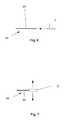
- FIG. 1 aillustrates an exploded view of a variation of the device.
- FIG. 1 bis a variation of cross-section 1 a.
- FIG. 2 aillustrates a variation of the device in a height-contracted configuration.
- FIG. 2 bis a variation of cross-section B-B of FIG. 2 a.
- FIG. 3 aillustrates a variation of the device in a height-expanded configuration.
- FIG. 3 bis a variation of cross-section C-C of FIG. 3 a.
- FIG. 4 ais a top view of a variation of the device in a height-contracted configuration.
- FIG. 4 bis a top view of a variation of the device in a height-expanded.
- FIGS. 5 a and 5 billustrate a variation of a method of expanding the device, shown in cross-sections B-B and C-C, respectively, of FIGS. 2 a and 3 a.
- FIG. 5 c and 5 dillustrate variations of a method for using the device having a variation of a cross-section C-C of FIG. 3 a with a deployment tool and/or locking rod.
- FIGS. 5 e through 5 gare a close up view of a method of using the deployment rod or locking pin with the second side port shown in a cross-sectional view.
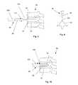
- FIGS. 6 and 7illustrate a variation of a method for using a delivery system for the expandable support element.
- FIGS. 8 through 10illustrate a variation of a method for accessing a damage site in the vertebra.
- FIG. 11illustrates two methods for delivering expandable support devices to the vertebral column.
- FIGS. 12 through 17illustrate various methods for deploying the expandable support device into the damage site in the vertebra.
- FIGS. 18 and 19illustrate a variation of a method for deploying one or more expandable support devices into one or more damage sites in the vertebra.
- FIG. 20illustrates a variation of a method for deploying the expandable support device into the damage site in the vertebra.
- FIG. 21illustrates variations of methods for deploying the expandable support device into the damage site in the vertebra.
- FIGS. 22 and 23illustrate a variation of a method for deploying the expandable support device into the damage site in the vertebra.
- FIGS. 24 through 27illustrate a variation of a method for deploying the expandable support device between adjacent vertebrae.
- FIGS. 28 through 31illustrate a variation of a method for deploying the expandable support device between adjacent vertebrae.
- FIGS. 32 and 33illustrate a variation of a method for deploying a locking pin into the expandable support device in the damage site in the vertebra.
- FIGS. 32 and 33illustrate a variation of a method for deploying a locking pin into the expandable support device in the damage site in the vertebra.
- FIGS. 34 a and 34 billustrate variations of methods for inserting one or more devices into one or more target sites.
- FIGS. 1 a and 1 billustrate an exploded view of an expandable support device 2 that can be implanted in a bone, such as a compression fracture in a vertebra, in the intervertebral space between two vertebrae, or in soft tissue, such as a herniated intervertebral disc.
- the expandable support device 2can be biocompatible.
- the expandable support device 2can be used, for example, for methods of repairing vertebral bone fractures or supporting adjacent vertebral bodies for fusion.
- the expandable support device 2can have a first longitudinal end and a second longitudinal end along a longitudinal axis 4 .
- the expandable support device 2can have a base or bottom 6 (base and bottom are used interchangeably), a middle 8 , and a top 10 .
- the base or bottom 6 and top 10can be or have plates, panels, struts (e.g., legs), ports, cells, and combinations thereof.
- the base 6 and top 10can be configured to be slidably attachable to the middle 8 .
- Either the top 10 , the base 6 , or neither, (shown in the figures as the base)can be slidably attached to the middle 8 in a plane parallel with the longitudinal axis 4 .
- Either the top 10 , the base 6 , or neither, (shown in the figures as the top 10 )can be slidably attached to the middle 8 in a plane substantially perpendicular to the longitudinal axis 4 .
- the top 10can have one or more top stability bars 12 .
- the top stability bars 12can extend from the lateral sides of the top 10 .
- the top stability bars 12can extend from the top 10 in the direction of the base 6 .
- the base 6can have one or more base stability grooves 14 .
- Each top stability bar 12can be configured to be slidably attachable to a corresponding base stability groove 14 .
- the top 10can have two sets of one, two or more symmetrically opposite, laterally located top stability bars 12 .
- the base 6can have two or more sets of two symmetrically opposite, laterally located base stability grooves 14 , as shown.
- the base 6can have one or more base stability bars 16 .
- the base stability bars 16can extend from the lateral sides of the base 6 .
- the base stability bars 16can extend from the bas 6 in the direction of the top 10 .
- the top 10can have one or more top stability grooves 18 .
- the base stability bars 16can each be configured to be slidably attachable to a corresponding top stability groove 18 .
- the base 6can have two sets of one, two, three (as shown) or more symmetrically opposite, laterally located base stability bars 16 .
- the top 10can have two or more sets of two, three (as shown) or more symmetrically opposite, laterally located top stability grooves 18 , as shown.
- the slidable attachment of the top 10 and base 6can permit the base 6 to move radially (with respect to the longitudinal axis 4 ) relative to the top and vice versa.
- the top 10can have a high-friction and/or low-friction texture extending away from the base 6 .
- the top 10can have one or numerous rows of top teeth 20 .
- the bottom 6can have a high-friction and/or low-friction texture extending away from the base 6 .
- the bottom 6can have one or numerous rows of bottom teeth 22 .
- the top teeth 20 and the bottom teeth 22can be arranged to have ridges parallel with the longitudinal access, transverse the parallel axis, a non-zero and non-right angle to the longitudinal axis 4 , or combinations thereof.
- the top 10can have one or more side ports and/or top ports 26 .
- the base 6can have one or more base ports 28 and/or side ports.
- the portscan be circular, square, triangular, oval, elongated in the longitudinal direction, elongated in the radial direction, or combinations thereof.
- the top 10 and/or base 6can have atraumatic edges, such as chamfered edges.
- the chamferscan extend along the perimeter of the base 6 and/or top 10 .
- the expandable support device 2can have one, two, three or more sets of interacting wedges or ramps.
- the sets of rampscan be distributed substantially evenly along the length of the device, or the sets of ramps can be distributed unevenly along the length of the base 6 .
- the rampscan all be oriented in the same direction (e.g., all ramps facing proximally, or all ramps facing distally), or can be oriented in different directions (e.g., some ramps facing distally and some ramps facing proximally).
- the top 10 and/or base 6can have a series of unidirectional and/or bidirectional ramps.
- the unidirectional rampscan be configured to have a ramp stop 30 at one longitudinal end of the ramp.
- the middle 8can have a series of unidirectional and/or bidrectional ramps.
- the unidirectional rampscan be configured to have a ramp stop 30 at one longitudinal end of the ramp.
- the rampscan have ramp tongues and grooves 32 .
- Ramp tongue and grooves 32 on corresponding rampscan be configured to slidably attach to the opposing tongues and grooves.
- the top ramps 34 , 36can have top tongues and grooves.
- the middle ramps 38 , 40 , 42can have middle tongues and grooves that can slidably engage the top tongues and grooves.
- the rampscan have ramp angles 44 with respect to the longitudinal axis 4 .
- the ramp angle 44can be from about 15° to about 75°, more narrowly from about 20° to about 60°, for example about 35°.
- One or more of the rampscan have a ramp stop 30 .
- the ramp stops 30can be configured to abut and interference fit against a corresponding ramp stop 30 on the adjacent element (i.e., the top 10 can be adjacent to the middle 8 ).
- the base 6 (as shown) and/or top 10can have a first side plate 46 .
- the base 6can have a base rail 48 .
- the middle 8can have a middle rail 50 .
- the middle rail 50can be slidably fed onto or under the base rail 48 .
- the base rail 48 and the middle rail 50can constrain relative motion between the middle 8 and the base 6 to the dimension of the longitudinal axis 4 .
- the first side port 52can have a first side outer port 54 on the first side plate 46 .
- the first side port 52can have a first side central port 56 in the top 10 .
- the first side central port 56can be open on the bottom 6 , for example to allow the first side central port 56 to move away from the first side outer port 54 without constraining any rod or other elongated element positioned through the first side port 52 .
- the middle 8can have a first side inner port 58 through the middle first ramp 38 .
- the first side outer 54 , central 56 , inner port 58 or a combination thereofcan be internally threaded.
- the first side outer port 54can form a recess in the first side plate 46 , for example to receive the head of a rod.
- the base 6can have one or more seat ramps, for example, the seat ramps can be positioned to correspond with and receive one or more of the top ramps, for example when the device is in a height-contracted configuration.
- the rampscan be positioned laterally symmetrically on the top 10 .
- the rampscan be evenly distributed along the length of the top 10 .
- the ramp seatscan be positioned laterally symmetrically on the base 6 .
- the rampscan be evenly distributed along the length of the base 6 .
- FIGS. 2 a and 2 billustrate that the device 2 can have a height-contracted configuration.
- Top rampscan receive the middle ramps.
- the ramp stops of the top rampscan interference fit against the ramp stops of the middle ramps.
- FIGS. 3 a and 3 billustrate that the device can have a height-expanded configuration.
- the middle 8can be slidably translated toward the first end.
- the stability barcan be configured to not directly attach to the top 10 when the top stability bar 12 is translated toward the base stability groove 14 , and/or the stability bars can be configured to bias inward against and frictionally hold the top 10 when the top 10 is translated into the base 6 .
- the top 10 and the base 6can be pressed into or otherwise translated toward each other.
- the surrounding tissue in the in vivo environmentcan naturally compress the expandable support device 2 .
- the rampscan have ratchets on their surface, in the tongue and groove or otherwise to prevent contraction once the device 2 is expanded.
- the device 2can be filled by a material, and/or the deployment rod can be fixed to the first side outer port 54 and the second port.
- the respective surfacescan have high friction surfaces, for example a textured (e.g., knurled) surface and/or coated with a high friction material.
- FIGS. 4 a and 4 billustrate that the top port 26 , middle port 27 and base port 28 substantially align transverse with the longitudinal axis 4 .
- the top/middle/base portsform a concurrent vertical port through the device 2 .
- the concurrent vertical portcan be filled with any material disclosed herein or left empty.
- the concurrent vertical portcan be partially obstructed by the middle 8 , including the middle first ramp 38 , when the device 2 is in a height-contracted configuration, as shown in FIG. 4 a .
- the concurrent vertical portcan be less obstructed, or substantially unobstructed when the device 2 is in a height-expanded configuration, as shown in FIG. 4 b.
- FIG. 4 aillustrates that the middle 8 can protrude outside of the footprint of the the top 10 and bottom 6 when the device 2 is viewed from above or below in a height-contracted configuration.
- FIG. 4 bfrom a top or bottom view, the middle 8 can be substantially flush with the top 10 and bottom 6 when viewed from above or below when the device 2 is in a height-contracted configuration.
- FIGS. 5 a and 5 billustrate. the height expansion, as shown by arrow, of the top 10 away from the base 6 .
- the height expansioncan occur when the device 2 is longitudinally compressed, and/or when the middle 8 is slid with respect to the base 6 toward the first side.
- FIG. 5 billustrates that the middle ramps slip, as shown by arrows, against the top ramps when the device 2 is expanded.
- FIG. 5 cillustrates that the middle 8 can have a second side port 68 .
- a deployment tool and/or locking rod 70can be inserted through the first port and the second side port 68 .
- the deployment rod 70can have an attached or integral deployment rod cap 72 or nut that can be outside the first port and interference fit with the wall surrounding the first port.
- the rod 72can be pulled (as shown by arrow), while a resistive force (shown by arrow) is applied to the device 2 to oppose the pulling force (to expand the device 2 rather than solely pulling the device 2 toward the user).
- the deployment rod 70 or locking pincan have a pin shaft with a driver slot, for example, configured to receive a screw driver or drill bit.
- the pin shaftcan have pin thread configured to releasably or fixedly attach to one or both of the ramp ports.
- the pin threadcan extend along all or part of the length of the pin shaft.
- the locking pincan be inserted, as shown by arrow, through the threaded ramp port.
- the deployment rod 70 and locking pincan be the same or different elements.
- the second side ramp 74 and/or the top 10 and/or the bottom 6can have a ramp abutment section, such as the ramp stops 30 .
- the ramp abutment sectioncan be configured to interference fit with and/of fixedly attach to the abutment end.
- a rod detent 76can be fitted onto or through the deployment tool or locking rod 70 .
- the usercan deploy a force against the detent 76 .
- the detent 76can be a clip, nut, brad, lockable slide, or combinations thereof.
- the detent 76can fix to the deployment rod 70 or locking pin and interference fit against the middle 8 .
- the middle 8can then be fixed between the rod detent 76 and the first side plate 46 .
- FIG. 5 dillustrates that the deployment rod or locking pin 80 can be integral or attached to the middle 8 , for example at the second side plate 47 .
- the middle portcan be unobstructed by the rod or pin.
- the deployment rod 70can be removably attached from the remainder of the device 2 , for example after the device 2 is deployed.
- the deployment rod 70can be used to position and expand the device 2 .
- FIG. 5 eillustrates that the second side port 68 can have port thread 78 on all or a portion of the inside of the port.
- the second side port 68can have port thread 78 on about half of the surface of the inside of the port, for example from angles about 0 degrees to about 180 degrees when measured from a longitudinal axis 4 passing through the center of the second side port 78 (as shown), or from about 0 degrees to about 90 degrees and then again from about 180 degrees to about 270 degrees.
- the deployment rod or locking pin 80can have rod/pin thread 82 on a portion of the surface of the rod or pin 80 corresponding to and substantially equal to or less than the portion of the surface of the inside of the port covered by port thread 78 .
- the rod or pin 80can have rod/pin thread 82 on about half of the surface of the outside of the rod or pin 80 , for example from angles about 0 degrees to about 180 degrees when measured from a longitudinal axis 4 passing through the center of the rod or pin 80 (as shown), or from about 0 degrees to about 90 degrees and then again from about 180 degrees to about 270 degrees.
- the non-threaded portion of the surface of the rod 80can be angularly aligned with the threaded portion of the surface of the second side port 68
- FIG. 5 fillustrates that the rod or pin 80 can be translated into or through the second side port 68 .
- the rod/pin thread 82can slidably pass across the inner surface of the second side port 68 not having port thread 78 .
- the port thread 78can slide past the outer surface of the second side port 68 not having port thread 78 .
- FIG. 5 gillustrates that when the rod or pin 80 is at a desired position, the rod or pin 80 can be rotated to align the rod/pin thread 82 with the port thread 78 .
- the rod or pin 80can be translatably fixed with respect to the second side port 68 .
- the partial-thread shown on the second side port 68 in FIGS. 5 e through 5 gcan be on a separate nut rotatably attached to the second side port 68 .
- the nutcan be rotated with respect to the rod or pin 80 to longitudinally fix the position of the rod or pin 80 with respect to the nut and therefore the second side port 68 .
- a biocompatible adhesive or epoxycan be applied to the pin thread 82 , threaded ramp port, abutment end, ramp abutment section, or combinations thereof.
- One, two or more locking pin channelscan be inserted longitudinally into the expandable support device 2 .
- One, two or more locking pins 80can be inserted into the same or separate ports, for example during or after deployment of the remainder of the expandable support device 2 .
- the locking pins 80can prevent overexpansion and/or overcompression and/or disassembly of the expandable support device 2 .
- the rampscan have locking pins 80 therethrough.
- the locking pin 80can be cylindrical.
- the locking pin channel and locking pin portcan have elongated cross-sections, such as an oval or rectangular or oblong cross-sections.
- the locking pin 80can be free to move vertically within a range of motion within the locking pin port.
- the locking pin 80can be a substantially similar shape and size as the locking pin channel.
- the locking pin 80can be substantially unmovable within the locking pin port.
- the locking pin 80 , locking pin channel and locking pin portcan all have elongated cross-sections, such as an oval or rectangular or oblong cross-sections.
- the rampscan have first fixing teeth or ratchets.
- the first fixing teethcan be in contact with the top 10 and/or the bottom 6 .
- the top and/or the bottomcan have second fixing teeth.
- the first fixing teethcan mechanically interact with the second fixing teeth to allow relative translation in a first direction.
- the first fixing teeth and the second fixing teethcan interact to obstruct (e.g., by interference fitting the first fixing teeth against the second fixing teeth) relative translation in a second direction.
- the fixing teethcan obstruct the top ramps from moving one way, for example not allowing the device to contract, and obstruct the top from moving closer to the bottom.
- the fixing teethcan allow relative translation of the side ramps toward each other, for example, to allow the top to move away from the bottom.
- the second side ramp 74can have a first end.
- the first endcan be configured to dissect tissue.
- the first endcan have a blunt or sharp point.
- the second side ramp 74can have a tool connector, such as an externally and/or internally threaded cylinder extending longitudinally from the second side ramp away from the first side ramp.
- the tool connectorcan be configured to removably attach to a deployment tool.
- the first fixing teethcan unidirectionally interference fit the second fixing teeth.
- the unidirectional interference fit of the first fixing teeth and the second fixing teethcan substantially impede or prevent the opposite ramps from moving longitudinally away from each other, for example, therefore impede or preventing compression of the top toward the bottom and vice versa.
- the unidirectional interference fit of the first fixing teeth and the second fixing teethcan allow the opposite ramps to move longitudinally toward each other, for example, therefore allowing the top to expand away from the bottom and vice versa.
- An external deployment toolcan be attached to the first side plate 46 and the second port 68 of the side of the device, and apply a compressive force across the device 2 .
- the base 6 and top 10can expand away from each other, as shown by arrows.
- the expandable support device 2When the expandable support device 2 is in a deployed configuration in vivo, the expandable support device 2 can be partially or substantially filled with a liquid, gel, or solid (e.g., in small parts or granules) filler material, or combinations thereof, such as bone morphogenic powder or any other material disclosed herein or combinations thereof.
- the filler materialcan contact or be in near contact with the surrounding tissue near the edge of the ports
- the expandable support devices 2can have textured and/or porous surfaces for example, to increase friction against bone surfaces, and/or promote tissue ingrowth.
- the expandable support devices 2can be coated with a bone growth factor, such as a calcium base.
- the expandable support device 2can be covered by a thin metal screen, for example over at least the top and/or base ports.
- the thin metal screencan expand and/or open when the expandable support device 2 expands.
- any or all elements of the expandable support device 2 and/or other devices or apparatuses described hereincan be made from, for example, a single or multiple stainless steel alloys, nickel titanium alloys (e.g., Nitinol), cobalt-chrome alloys (e.g., ELGILOY® from Elgin Specialty Metals, Elgin, Ill.; CONICHROME® from Carpenter Metals Corp., Wyomissing, Pa.), nickel-cobalt alloys (e.g., MP35N® from Magellan Industrial Trading Company, Inc., Westport, Conn.), molybdenum alloys (e.g., molybdenum TZM alloy, for example as disclosed in International Pub. No.
- WO 03/082363 A2published 9 Oct. 2003, which is herein incorporated by reference in its entirety
- tungsten-rhenium alloysfor example, as disclosed in International Pub. No. WO 03/082363
- polymerssuch as polyethylene teraphathalate (PET)/polyester (e.g., DACRON® from E. I.
- PGApolyglycolic acid
- PLApolylactic
- any or all elements of the expandable support device 2 and/or other devices or apparatuses described hereincan be, have, and/or be completely or partially coated with agents and/or a matrix a matrix for cell ingrowth or used with a fabric, for example a covering (not shown) that acts as a matrix for cell ingrowth.
- the matrix and/or fabriccan be, for example, polyester (e.g., DACRON® from E. I. Du Pont de Nemours and Company, Wilmington, Del.), polypropylene, PTFE, ePTFE, nylon, extruded collagen, silicone or combinations thereof.
- the expandable support device 2 and/or elements of the expandable support device 2 and/or other devices or apparatuses described herein and/or the fabriccan be filled, coated, layered and/or otherwise made with and/or from cements, fillers, glues, and/or an agent delivery matrix known to one having ordinary skill in the art and/or a therapeutic and/or diagnostic agent. Any of these cements and/or fillers and/or glues can be osteogenic and osteoinductive growth factors.
- cements and/or fillersexamples include bone chips, demineralized bone matrix (DBM), calcium sulfate, coralline hydroxyapatite, biocoral, tricalcium phosphate, calcium phosphate, polymethyl methacrylate (PMMA), biodegradable ceramics, bioactive glasses, hyaluronic acid, lactoferrin, bone morphogenic proteins (BMPs) such as recombinant human bone morphogenetic proteins (rhBMPs), other materials described herein, or combinations thereof.
- DBMdemineralized bone matrix
- PMMApolymethyl methacrylate
- BMPsbone morphogenic proteins
- rhBMPsrecombinant human bone morphogenetic proteins
- the agents within these matricescan include any agent disclosed herein or combinations thereof, including radioactive materials; radiopaque materials; cytogenic agents; cytotoxic agents; cytostatic agents; thrombogenic agents, for example polyurethane, cellulose acetate polymer mixed with bismuth trioxide, and ethylene vinyl alcohol; lubricious, hydrophilic materials; phosphor cholene; anti-inflammatory agents, for example non-steroidal anti-inflammatories (NSAIDs) such as cyclooxygenase-1 (COX-1) inhibitors (e.g., acetylsalicylic acid, for example ASPIRIN® from Bayer AG, Leverkusen, Germany; ibuprofen, for example ADVIL® from Wyeth, Collegeville, Pa.; indomethacin; mefenamic acid), COX-2 inhibitors (e.g., VIOXX® from Merck & Co., Inc., Whitehouse Station, N.J.; CELEBREX®
- the expandable support devices 2can be laser cut, machined, cut by wire electrical discharge machining (“EDM”) or made by other suitable techniques.
- EDMelectrical discharge machining
- the expandable support device 2can be cut in a fully contracted or unexpanded configuration or may be cut in a partially opened pattern, then loaded (e.g., crimped) onto a deployment tool 84 (e.g., balloon).
- the loaded expandable support device 2can have a smaller profile while plastically deforming the struts past their limits.
- the expandable support device 2can be longitudinally segmented. Multiple expandable support devices 2 can be attached first end to second end, and/or a single expandable support device 2 can be severed longitudinally into multiple expandable support devices 2 .
- FIG. 6illustrates that the expandable support device 2 can be loaded in a collapsed (i.e., contracted) configuration onto a deployment tool 84 .
- the deployment tool 84can be configured to removably attach to the first side ramp and the second side ramp.
- One or more deployment toolscan be configured to control the position of the expandable support device 2 (e.g., to rigidly attach to the expandable support device 2 ) and/or to longitudinally compress the second side ramps 74 , and/or to deploy one or more locking pins in the expandable support device 2 .
- the deployment tool 84can include a rigid or flexible catheter 86 .
- FIG. 7illustrates that the deployment tool 86 can longitudinally compress the expandable support device 2 , for example causing the expandable support device 2 to vertically expand as shown by arrows.
- FIGS. 8 (side view) and 9 (top view)illustrate a vertebral column 88 that can have one or more vertebra 90 separated from the other vertebra 90 by discs 92 .
- the vertebra 90can have a damage site 94 , for example a compression fracture.
- An access tool 96can be used to gain access to the damage site 94 and or increase the size of the damage site 94 to allow deployment of the expandable support device 2 .
- the access tool 96can be a rotating or vibrating drill 98 that can have a handle 100 .
- the drill 98may oscillate, as shown by arrows 102 .
- the drill 98can then be translated, as shown by arrow 104 , toward and into the vertebra 90 so as to pass into the damage site 94 .
- FIG. 10illustrates that the access tool 96 can be translated, as shown by arrow 106 , to remove tissue at the damage site 94 .
- the access tool 96can create an access port 108 at the surface of the vertebra 90 .
- the access port 108can open to the damage site 94 .
- the access tool 96can then be removed from the vertebra 90 .
- FIG. 11illustrates that a first deployment tool 110 can enter posteriorly through the subject's back.
- the first deployment tool 110can enter through a first incision 112 in the skin 114 on the posterior side 116 of the subject near the vertebral column 88 .
- the first deployment tool 110can be translated, as shown by arrow 118 , to position a first expandable support device 120 into a first damage site 122 .
- the first access port 124can be on the posterior side 116 of the vertebra 90 .
- a second deployment tool 126can enter through a second incision 128 (as shown) in the skin 114 .
- the second incision 130may be posterior (as shown) or may be anterior, lateral, posterior lateral, or the like.
- the second deployment tool 126can be translated through muscle (not shown), around nerves 132 , the spinal cord 134 , and anterior 136 of the vertebral column 88 .
- the second deployment tool 126can be steerable.
- the second deployment tool 126can be steered, as shown by arrow 138 , to align the distal tip of the second expandable support device 140 with a second access port 142 on a second damage site 144 .
- the second access port 142can face anteriorly 136 .
- the second deployment toolcan translate, as shown by arrow 146 , to position the second expandable support device 140 in the second damage site 144 .
- the vertebra 90can have multiple damage sites and expandable support devices deployed therein.
- the expandable support devicescan be deployed from the anterior 136 , posterior 116 , both lateral, superior, inferior, any angle, or combinations of the directions thereof.
- a single devicemay be deployed from one direction rather than multiple devices from multiple directions.
- FIGS. 12 and 13illustrate translating, as shown by arrow, the deployment tool 84 loaded with the expandable support device 2 through the access port 108 from the anterior side 136 of the vertebral column 88 .
- FIGS. 14 and 15illustrate that the deployment tool 84 can be deployed from the posterior side 116 of the vertebral column 88 .
- the deployment tool 84can be deployed off-center, for example, when approaching the posterior side 116 of the vertebral column 88 .
- FIG. 16illustrates that deployment tool 84 can position the expandable support device 2 in the vertebra 90 and into the damage site 94 .
- FIG. 17illustrates that the expandable support device 2 can be longitudinally compressed (i.e., vertically expanded) until the expandable support device 2 is substantially fixed to the vertebra 90 .
- the expandable support device 2can reshape the vertebral column 88 to a more natural configuration during expansion of the device.
- FIGS. 18 and 19illustrate that first and second deployment tools 110 and 126 can position and deploy first and second expandable support devices 120 and 140 simultaneously, and/or in the same vertebra 90 and into the same or different damage sites 122 and 144 .
- FIG. 20illustrates that the access port 108 can be made close to the disc 92 , for example when the damage site 94 is close to the disc 92 .
- the deployment tool 84can be inserted through the access port 108 and the expandable support device 2 can be deployed as described supra.
- FIG. 21a front view of the vertebral column 88 , illustrates that more than one expandable support device 2 can be deployed into a single vertebra 90 .
- a first expandable support device(not shown) can be inserted through a first access port 124 and deployed in a first damage site 122
- a second expandable support device(not shown) can be inserted through a first access port 124 and deployed in a second damage site 144 .
- the first access port 124can be substantially centered with respect to the first damage site 122 .
- the first expandable support device(not shown) can expand, as shown by arrows 148 , substantially superiorly and inferiorly, aligned with the center of the first access port 124 .
- the second access port 142can be substantially not centered with respect to the second damage site 144 .
- the second expandable support devicecan substantially anchor to a side of the damage site 94 and/or the surface of the disc 92 , and then expand, as shown by arrows 150 , substantially directionally away from the disc 92 .
- FIG. 22illustrates that when compressive tension from the deployment tool 84 is no longer exerted on the expandable support device 2 , the expandable support device 2 can be self-locking and/or a fixation pin can be inserted before, during or after the compressive tension is stopped. The expandable support device 2 can then be substantially fixed to the vertebra 90 at the damage site 94 . For example, the expandable support device 2 can be subject to biomechanical compression within one or between two vertebrae 90 .
- the access port 108can have an access port diameter 152 .
- the access port diameter 152can be from about 1.5 mm (0.060 in.) to about 40 mm (2 in.), for example about 8 mm (0.3 in.).
- the access port diameter 152can be a result of the size of the access tool 96 and in the unexpanded expandable support device 2 .
- the damage site 94can have a deployed diameter 154 .
- the deployed diameter 154can be from about 1.5 mm (0.060 in.) to about 120 mm (4.7 in.), for example from about 10 mm (0.4 in.) to about 20 mm (0.8 in.), or from about 12 mm (0.47 in.) to about 16 mm (0.63 in.).
- the deployed diameter 154can be greater than, equal to, or less than the access port diameter 152 .
- FIG. 23illustrates that the deployment tool 84 can be removed, as shown, from the vertebra 90 after the expandable support device 2 is deployed.
- FIG. 24illustrates that the expandable support device 2 can be loaded onto the deployment tool 84 .
- the expandable support device 2can be positioned adjacent to the disc 92 .
- the disc 92can be between a first vertebra 90 a and a second vertebra 90 b.
- FIG. 25illustrates that the expandable support device 2 can be inserted into the disc 92 , for example into the nuclear space or into the annular space. Removal of none, part or all of the nucleus and/or annulus can be performed before placing the expandable support device 2 in the disc 92 .
- FIG. 26illustrates that the expandable support device 2 can be radially expanded, as shown by arrows, in the space of the disc 92 a .
- Rough texturing, ingrowth matrix, teeth, or combinations thereof on the top or bottom of the expandable support device 2can engage the first or second vertebrae 90 a or 90 b or both.
- the expandable support device 2can fuse or fix the first vertebra 90 a to the second vertebra 90 b .
- the expandable support device 2can increase the gap between the first vertebra 90 a and the second vertebra 90 b (e.g., to restore proper or original biomechanics and/or anatomical geometry).
- FIG. 27illustrates that the deployment tool 84 can be disconnected from the expandable support device 2 .
- the deployment tool 84can be removed from the space of the disc 92 a with or without the expandable support device 2 .
- FIGS. 28 through 31illustrate a method of deploying the variation of the expandable support device 2 .
- FIG. 28illustrates that the expandable support device 2 can be attached to the deployment tool 84 .
- the expandable support device 2can be positioned adjacent to the target site, such as the disc space 92 a and/or a vertebra 90 .
- FIG. 29illustrates that the deployment tool 84 can translate and rotate the expandable support device 2 to the target site.
- FIG. 30illustrates that the expandable support device 2 can be longitudinally compressed and radially expanded, as shown by arrows.
- FIG. 31illustrates that the deployment tool 84 can be separated from the expandable support device 2 .
- the deployment tool 84can be removed from the target site.
- the expandable support device 2can be left in the target site or removed.
- FIGS. 32 and 33illustrate that a locking pin 80 can be inserted, as shown by arrow, into the deployed expandable support device 2 , for example, after the expandable support device 2 is deployed in the vertebra 90 .
- the locking pin 80can prevent the expandable support device 2 from collapsing after the expandable support device 2 is deployed in the vertebra 90 .
- the locking pin 80can form an interference fit with the expandable support device 2 or may include features to hold the locking pin in place.
- FIG. 34 aillustrates that one, two or more devices 2 , such as a first device 120 and a second device 140 , can be inserted, deployed and/or implanted the target site, such as in a vertebral body 158 or on a vertebral body 158 (e.g., between adjacent vertebral bodies).
- the devices 2can be oriented so the longitudinal axes 4 of the devices 2 are substantially parallel with an anterior-posterior axis 160 of the patient.
- the first device 120can be oriented so the first device longitudinal axis 4 a can be substantially parallel with the anterior-posterior axis 160 .
- the second device 140can be oriented so the second device longitudinal axis 4 b can be substantially parallel with the anterior-posterior axis 160 .
- the second device 140can be positioned in a substantially symmetric location and angular orientation to the first device 120 with respect to the anterior-posterior axis 160 .
- the device 2can be longitudinally contracted and radially expanded.
- the second device 140has been radially expanded, and the first device 120 has been delivered to the target site and not yet radially expanded.
- Multiple devicescan be delivered concurrently or sequentially.
- Multiple devicescan be radially expanded sequentially or concurrently.
- the devicescan be inserted with a surgical technique such as an Anterior Lumbar Interbody Fusion (ALIF), shown by arrow 162 , Posterior Lumbar Interbody Fusion (PLIF), shown by arrow 164 , Transforaminal Lumbar interbody Fusion (TLIF), shown by arrow 166 , a direct linear lateral delivery, as shown by arrow 168 , a curvilinear lateral delivery initially inserted posteriorly, as shown by arrow 170 , or other methods or combinations thereof.
- ALIFAnterior Lumbar Interbody Fusion
- PLIFPosterior Lumbar Interbody Fusion
- TLIFTransforaminal Lumbar interbody Fusion
- Operative planning and templatingcan be performed using MRI and CAT imaging scans to determine what size device fits the patient's anatomy and pathology.
- the disc (i.e., intervertebral) space or other target sitecan then be prepared.
- the vertebraecan be accessed through an incision in the patient's back (i.e., posterior to the vertebrae). Depending on the number of vertebral levels to be fused, about a 3-6 inch incision can be made in the patient's back.
- the spinal musclescan then be retracted (or separated), for example, to allow access to the target vertebral discs.
- the laminacan then be removed (i.e., a laminectomy), for example, to be able to see and access the nerve roots.
- the facet joints, which can lie directly over the nerve roots,can be trimmed, for example, to allow more room for the nerve roots.
- the target disc and surrounding tissuecan then be removed and the bone surfaces of adjacent vertebrae can be prepared (e.g., cleaned, abraded, debrided, textured, scored, coated with osteogenic powders or other agents, or combinations thereof).
- the devices 2can then be inserted into the target site.
- One or more devices 2 and/or bone grafte.g., autograft, allograft, xenograft), BMP, or combinations thereof, can be inserted into the target site or disc space, for example, to promote fusion between the vertebrae.
- Additional instrumentatione.g., rods or screws
- rods or screwscan also be used at this time to further stabilize the spine.
- TLIFcan include delivering the device 2 to the spine in a path more from the side of the spinal canal than a PLIF approach and through a midline incision in the patient's back. TLIF can reduce the amount of surgical muscle dissection and can minimizes nerve manipulation required to access the vertebrae, discs and nerves.
- TLIFcan include removing disc material from the spine and inserting the device(s) 2 and bone graft, BMP, screws, rods, or combinations thereof.
- ALIFis performed inserting from the front (anterior) of the body, usually through a 3-5 inch incision in the lower abdominal area or on the side. This incision may involve cutting through, and later repairing, the muscles in the lower abdomen.
- a mini open ALIF approachcan be performed.
- a mini open ALIFcan preserves the muscles and allow access to the front of the spine through an incision. This approach maintains abdominal muscle strength and function and can be used to fuse the L5-S1 disc space, for example
- the disc materialcan be removed.
- the surgeoncan then insert the devices 2 and/or bone graft, rods, screws, BMP, or combinations thereof, for example to stabilize the spine and facilitate fusion.
- the target site for the device(s) 2can be between sacral, lumbar, thoracic, cervical vertebrae, or combinations thereof.
- the target sitecan be between other bones, such as intercostal (between ribs), in the knee, elbow, wrist, ankle, or combinations thereof.
- FIG. 34 billustrates that one (as shown) or more devices 2 can be inserted into the target site, such as in a vertebral body 158 or on a vertebral body 158 (e.g., between adjacent vertebral bodies).
- the longitudinal axis 4 of the device 2can be oriented substantially perpendicular to the anterior-posterior axis 160 (i.e., parallel to a lateral axis).
Landscapes
- Health & Medical Sciences (AREA)
- Engineering & Computer Science (AREA)
- Biomedical Technology (AREA)
- Orthopedic Medicine & Surgery (AREA)
- Life Sciences & Earth Sciences (AREA)
- General Health & Medical Sciences (AREA)
- Neurology (AREA)
- Surgery (AREA)
- Veterinary Medicine (AREA)
- Heart & Thoracic Surgery (AREA)
- Public Health (AREA)
- Animal Behavior & Ethology (AREA)
- Cardiology (AREA)
- Vascular Medicine (AREA)
- Transplantation (AREA)
- Nuclear Medicine, Radiotherapy & Molecular Imaging (AREA)
- Oral & Maxillofacial Surgery (AREA)
- Medical Informatics (AREA)
- Molecular Biology (AREA)
- Prostheses (AREA)
- Surgical Instruments (AREA)
Abstract
Description
Claims (8)
Priority Applications (1)
| Application Number | Priority Date | Filing Date | Title |
|---|---|---|---|
| US12/780,744US8382842B2 (en) | 2009-05-14 | 2010-05-14 | Expandable support device and method of use |
Applications Claiming Priority (2)
| Application Number | Priority Date | Filing Date | Title |
|---|---|---|---|
| US17835509P | 2009-05-14 | 2009-05-14 | |
| US12/780,744US8382842B2 (en) | 2009-05-14 | 2010-05-14 | Expandable support device and method of use |
Publications (2)
| Publication Number | Publication Date |
|---|---|
| US20100292796A1 US20100292796A1 (en) | 2010-11-18 |
| US8382842B2true US8382842B2 (en) | 2013-02-26 |
Family
ID=43069162
Family Applications (1)
| Application Number | Title | Priority Date | Filing Date |
|---|---|---|---|
| US12/780,744Active2030-11-08US8382842B2 (en) | 2009-05-14 | 2010-05-14 | Expandable support device and method of use |
Country Status (2)
| Country | Link |
|---|---|
| US (1) | US8382842B2 (en) |
| WO (1) | WO2010132841A1 (en) |
Cited By (165)
| Publication number | Priority date | Publication date | Assignee | Title |
|---|---|---|---|---|
| US20120245691A1 (en)* | 2011-03-23 | 2012-09-27 | Alphatec Spine, Inc. | Expandable interbody spacer |
| US20120323327A1 (en)* | 2011-06-17 | 2012-12-20 | Mcafee Paul C | Expandable Spinal Implant and Flexible Driver |
| US20130123927A1 (en)* | 2010-07-15 | 2013-05-16 | Spine Wave, Inc. | Plastically deformable inter-osseous device |
| US20130304214A1 (en)* | 2011-07-14 | 2013-11-14 | Nlt Spine Ltd. | Laterally Deflectable Implant |
| US20140163682A1 (en)* | 2012-12-11 | 2014-06-12 | Expandable Vertebral Implant | Expandable Vertebral Implant |
| US8771277B2 (en) | 2012-05-08 | 2014-07-08 | Globus Medical, Inc | Device and a method for implanting a spinous process fixation device |
| US8828019B1 (en) | 2013-03-13 | 2014-09-09 | Spine Wave, Inc. | Inserter for expanding an expandable interbody fusion device |
| US20140343677A1 (en)* | 2013-05-14 | 2014-11-20 | Spine View, Inc. | Intervertebral devices and related methods |
| US8900312B2 (en) | 2013-03-12 | 2014-12-02 | Spine Wave, Inc. | Expandable interbody fusion device with graft chambers |
| US9011493B2 (en) | 2012-12-31 | 2015-04-21 | Globus Medical, Inc. | Spinous process fixation system and methods thereof |
| US9023108B2 (en) | 2005-04-21 | 2015-05-05 | Globus Medical Inc | Expandable vertebral prosthesis |
| US9028498B2 (en) | 2013-03-14 | 2015-05-12 | Innovasis, Inc. | Modular bone fixation plate assembly |
| US9034045B2 (en) | 2013-03-15 | 2015-05-19 | Globus Medical, Inc | Expandable intervertebral implant |
| US9078767B1 (en) | 2014-03-06 | 2015-07-14 | Spine Wave, Inc. | Expandable spinal interbody fusion device |
| US9101489B2 (en) | 2013-10-07 | 2015-08-11 | Spine Wave, Inc. | Expandable anterior lumbar interbody fusion device |
| WO2015120235A1 (en)* | 2014-02-07 | 2015-08-13 | Globus Medical, Inc. | Variable lordosis spacer and related methods of use |
| US9149367B2 (en) | 2013-03-15 | 2015-10-06 | Globus Medical Inc | Expandable intervertebral implant |
| US9186258B2 (en) | 2013-03-15 | 2015-11-17 | Globus Medical, Inc. | Expandable intervertebral implant |
| US9198697B2 (en) | 2013-03-13 | 2015-12-01 | Globus Medical, Inc. | Spinous process fixation system and methods thereof |
| US9204972B2 (en) | 2013-03-01 | 2015-12-08 | Globus Medical, Inc. | Articulating expandable intervertebral implant |
| US9216096B2 (en) | 2010-03-16 | 2015-12-22 | Pinnacle Spine Group, Llc | Intervertebral implants and related tools |
| WO2016019230A1 (en)* | 2014-08-01 | 2016-02-04 | Globus Medical, Inc. | Variable lordosis spacer and related methods of use |
| US9265623B2 (en) | 2014-03-06 | 2016-02-23 | Spine Wave, Inc. | Method of expanding a spinal interbody fusion device |
| US9295562B2 (en) | 2008-01-17 | 2016-03-29 | DePuy Synthes Products, Inc. | Expandable intervertebral implant and associated method of manufacturing the same |
| US9320614B2 (en) | 2006-07-31 | 2016-04-26 | DePuy Synthes Products, Inc. | Spinal fusion implant |
| US9320615B2 (en) | 2010-06-29 | 2016-04-26 | DePuy Synthes Products, Inc. | Distractible intervertebral implant |
| US9333091B2 (en) | 2003-02-14 | 2016-05-10 | DePuy Synthes Products, Inc. | In-situ formed intervertebral fusion device and method |
| US9351848B2 (en) | 2010-09-03 | 2016-05-31 | Globus Medical, Inc. | Expandable fusion device and method of installation thereof |
| US9380932B1 (en) | 2011-11-02 | 2016-07-05 | Pinnacle Spine Group, Llc | Retractor devices for minimally invasive access to the spine |
| US9393130B2 (en) | 2013-05-20 | 2016-07-19 | K2M, Inc. | Adjustable implant and insertion tool |
| US9402738B2 (en) | 2013-02-14 | 2016-08-02 | Globus Medical, Inc. | Devices and methods for correcting vertebral misalignment |
| US9402737B2 (en) | 2007-06-26 | 2016-08-02 | DePuy Synthes Products, Inc. | Highly lordosed fusion cage |
| US9414934B2 (en) | 2008-04-05 | 2016-08-16 | DePuy Synthes Products, Inc. | Expandable intervertebral implant |
| US9414936B2 (en) | 2011-12-19 | 2016-08-16 | Warsaw Orthopedic, Inc. | Expandable interbody implant and methods of use |
| USD766346S1 (en) | 2013-11-21 | 2016-09-13 | Ergotron, Inc. | Recirculating bearing |
| US9439783B2 (en) | 2014-03-06 | 2016-09-13 | Spine Wave, Inc. | Inserter for expanding body tissue |
| US9445919B2 (en) | 2011-12-19 | 2016-09-20 | Warsaw Orthopedic, Inc. | Expandable interbody implant and methods of use |
| US9445921B2 (en) | 2014-03-06 | 2016-09-20 | Spine Wave, Inc. | Device for expanding and supporting body tissue |
| US9445920B2 (en) | 2014-06-03 | 2016-09-20 | Atlas Spine, Inc. | Spinal implant device |
| US9486251B2 (en) | 2012-12-31 | 2016-11-08 | Globus Medical, Inc. | Spinous process fixation system and methods thereof |
| WO2016200631A1 (en)* | 2015-06-11 | 2016-12-15 | Spine Wave, Inc. | Device for expanding and supporting body tissue |
| US9526620B2 (en) | 2009-03-30 | 2016-12-27 | DePuy Synthes Products, Inc. | Zero profile spinal fusion cage |
| US9561117B2 (en) | 2012-07-26 | 2017-02-07 | DePuy Synthes Products, Inc. | Expandable implant |
| US9566168B2 (en) | 2010-09-03 | 2017-02-14 | Globus Medical, Inc. | Expandable fusion device and method of installation thereof |
| US9566167B2 (en) | 2013-08-22 | 2017-02-14 | K2M, Inc. | Expandable spinal implant |
| US9585765B2 (en) | 2013-02-14 | 2017-03-07 | Globus Medical, Inc | Devices and methods for correcting vertebral misalignment |
| US9592063B2 (en) | 2010-06-24 | 2017-03-14 | DePuy Synthes Products, Inc. | Universal trial for lateral cages |
| US9599153B2 (en) | 2014-12-03 | 2017-03-21 | Ergotron, Inc. | Bearing assembly and method |
| US9622876B1 (en) | 2012-04-25 | 2017-04-18 | Theken Spine, Llc | Expandable support device and method of use |
| US9662224B2 (en) | 2014-02-07 | 2017-05-30 | Globus Medical, Inc. | Variable lordosis spacer and related methods of use |
| US9700425B1 (en) | 2011-03-20 | 2017-07-11 | Nuvasive, Inc. | Vertebral body replacement and insertion methods |
| US9713536B2 (en) | 2015-08-12 | 2017-07-25 | Warsaw Orthopedic, Inc. | Expandable spinal implant and method of implanting same |
| US9717601B2 (en) | 2013-02-28 | 2017-08-01 | DePuy Synthes Products, Inc. | Expandable intervertebral implant, system, kit and method |
| US9730806B2 (en) | 2014-10-27 | 2017-08-15 | Warsaw Orthopedic, Inc. | Spinal implant system and method |
| US9750552B2 (en) | 2009-07-06 | 2017-09-05 | DePuy Synthes Products, Inc. | Expandable fixation assemblies |
| US9782265B2 (en) | 2013-02-15 | 2017-10-10 | Globus Medical, Inc | Articulating and expandable vertebral implant |
| US9788971B1 (en) | 2013-05-22 | 2017-10-17 | Nuvasive, Inc. | Expandable fusion implant and related methods |
| US9801734B1 (en) | 2013-08-09 | 2017-10-31 | Nuvasive, Inc. | Lordotic expandable interbody implant |
| US9801725B2 (en) | 2009-12-09 | 2017-10-31 | DePuy Synthes Products, Inc. | Aspirating implants and method of bony regeneration |
| US9827025B2 (en) | 2015-11-20 | 2017-11-28 | Globus Medical, Inc. | Expandable intramedullary systems and methods of using the same |
| US9833334B2 (en) | 2010-06-24 | 2017-12-05 | DePuy Synthes Products, Inc. | Enhanced cage insertion assembly |
| US9839528B2 (en) | 2014-02-07 | 2017-12-12 | Globus Medical, Inc. | Variable lordosis spacer and related methods of use |
| US9907670B2 (en) | 2015-01-21 | 2018-03-06 | Warsaw Orthopedic, Inc. | Unitarily formed expandable spinal implant and method of manufacturing and implanting same |
| US9913727B2 (en) | 2015-07-02 | 2018-03-13 | Medos International Sarl | Expandable implant |
| US9931224B2 (en) | 2009-11-05 | 2018-04-03 | DePuy Synthes Products, Inc. | Self-pivoting spinal implant and associated instrumentation |
| US9937053B2 (en) | 2014-11-04 | 2018-04-10 | Warsaw Orthopedic, Inc. | Expandable interbody implant |
| US9937054B2 (en) | 2016-01-28 | 2018-04-10 | Warsaw Orthopedic, Inc. | Expandable implant and insertion tool |
| US9956087B2 (en) | 2015-07-17 | 2018-05-01 | Globus Medical, Inc | Intervertebral spacer and plate |
| USD816844S1 (en) | 2017-06-29 | 2018-05-01 | American Medical Ortho Systems LLC | Lumbar interbody implant |
| US9974581B2 (en) | 2015-11-20 | 2018-05-22 | Globus Medical, Inc. | Expandable intramedullary systems and methods of using the same |
| US9987144B2 (en) | 2015-07-17 | 2018-06-05 | Globus Medical, Inc. | Intervertebral spacer and plate |
| US9993349B2 (en) | 2002-06-27 | 2018-06-12 | DePuy Synthes Products, Inc. | Intervertebral disc |
| US10016284B2 (en) | 2005-04-12 | 2018-07-10 | Moskowitz Family Llc | Zero-profile expandable intervertebral spacer devices for distraction and spinal fusion and a universal tool for their placement and expansion |
| US10016282B2 (en) | 2015-07-17 | 2018-07-10 | Globus Medical, Inc. | Intervertebral spacer and plate |
| US10022245B2 (en) | 2012-12-17 | 2018-07-17 | DePuy Synthes Products, Inc. | Polyaxial articulating instrument |
| US10070970B2 (en) | 2013-03-14 | 2018-09-11 | Pinnacle Spine Group, Llc | Interbody implants and graft delivery systems |
| US10076423B2 (en) | 2016-01-04 | 2018-09-18 | Warsaw Orthopedic, Inc. | Pivoting wedge expanding spinal implant and method of implanting same |
| US10092333B2 (en) | 2015-11-20 | 2018-10-09 | Globus Medical, Inc. | Expandable intramedullary systems and methods of using the same |
| US10105239B2 (en) | 2013-02-14 | 2018-10-23 | Globus Medical, Inc. | Devices and methods for correcting vertebral misalignment |
| US10117754B2 (en) | 2013-02-25 | 2018-11-06 | Globus Medical, Inc. | Expandable intervertebral implant |
| WO2018208583A1 (en)* | 2017-05-08 | 2018-11-15 | Medos International Sàrl | Expandable cage |
| US10137006B2 (en) | 2016-01-28 | 2018-11-27 | Warsaw Orthopedic, Inc. | Geared cam expandable interbody implant and method of implanting same |
| US10159582B2 (en) | 2011-09-16 | 2018-12-25 | DePuy Synthes Products, Inc. | Removable, bone-securing cover plate for intervertebral fusion cage |
| US10188526B2 (en) | 2015-10-26 | 2019-01-29 | Warsaw Orthopedic, Inc. | Spinal implant system and method |
| US10195053B2 (en) | 2009-09-18 | 2019-02-05 | Spinal Surgical Strategies, Llc | Bone graft delivery system and method for using same |
| USD841167S1 (en) | 2017-08-16 | 2019-02-19 | American Medical Ortho Systems LLC | Lumbar interbody implant |
| US10245159B1 (en) | 2009-09-18 | 2019-04-02 | Spinal Surgical Strategies, Llc | Bone graft delivery system and method for using same |
| US10299934B2 (en) | 2012-12-11 | 2019-05-28 | Globus Medical, Inc | Expandable vertebral implant |
| US10363142B2 (en) | 2014-12-11 | 2019-07-30 | K2M, Inc. | Expandable spinal implants |
| US10369015B2 (en) | 2010-09-23 | 2019-08-06 | DePuy Synthes Products, Inc. | Implant inserter having a laterally-extending dovetail engagement feature |
| US10376377B2 (en) | 2015-07-17 | 2019-08-13 | Globus Medical, Inc. | Intervertebral spacer and plate |
| US10390963B2 (en) | 2006-12-07 | 2019-08-27 | DePuy Synthes Products, Inc. | Intervertebral implant |
| US10441430B2 (en) | 2017-07-24 | 2019-10-15 | K2M, Inc. | Expandable spinal implants |
| US10500062B2 (en) | 2009-12-10 | 2019-12-10 | DePuy Synthes Products, Inc. | Bellows-like expandable interbody fusion cage |
| US10537436B2 (en) | 2016-11-01 | 2020-01-21 | DePuy Synthes Products, Inc. | Curved expandable cage |
| US10610376B2 (en) | 2015-10-16 | 2020-04-07 | Warsaw Orthopedic, Inc. | Expandable spinal implant system and method |
| US10779955B2 (en) | 2015-10-26 | 2020-09-22 | Warsaw Orthopedic, Inc. | Spinal implant system and method |
| US10888433B2 (en) | 2016-12-14 | 2021-01-12 | DePuy Synthes Products, Inc. | Intervertebral implant inserter and related methods |
| US10940016B2 (en) | 2017-07-05 | 2021-03-09 | Medos International Sarl | Expandable intervertebral fusion cage |
| US10966843B2 (en) | 2017-07-18 | 2021-04-06 | DePuy Synthes Products, Inc. | Implant inserters and related methods |
| US10973656B2 (en) | 2009-09-18 | 2021-04-13 | Spinal Surgical Strategies, Inc. | Bone graft delivery system and method for using same |
| US11045331B2 (en) | 2017-08-14 | 2021-06-29 | DePuy Synthes Products, Inc. | Intervertebral implant inserters and related methods |
| US11045326B2 (en) | 2015-07-17 | 2021-06-29 | Global Medical Inc | Intervertebral spacer and plate |
| US11051951B2 (en) | 2013-03-15 | 2021-07-06 | Spectrum Spine Ip Holdings, Llc | Expandable inter-body fusion devices and methods |
| US11065132B2 (en) | 2014-03-06 | 2021-07-20 | Spine Wave, Inc. | Method of expanding a space between opposing tissue surfaces |
| US11083595B2 (en) | 2014-10-28 | 2021-08-10 | Spectrum Spine Ip Holdings, Llc | Expandable, adjustable inter-body fusion devices and methods |
| USRE48719E1 (en) | 2014-10-09 | 2021-09-07 | K2M, Inc. | Expandable spinal interbody spacer and method of use |
| US11285014B1 (en) | 2020-11-05 | 2022-03-29 | Warsaw Orthopedic, Inc. | Expandable inter-body device, system, and method |
| US11291554B1 (en) | 2021-05-03 | 2022-04-05 | Medtronic, Inc. | Unibody dual expanding interbody implant |
| US11344424B2 (en) | 2017-06-14 | 2022-05-31 | Medos International Sarl | Expandable intervertebral implant and related methods |
| US11369483B2 (en) | 2015-07-17 | 2022-06-28 | Expanding Innovations, Inc. | Intervertebral devices and related methods |
| US11369490B2 (en) | 2011-03-22 | 2022-06-28 | DePuy Synthes Products, Inc. | Universal trial for lateral cages |
| US11376134B1 (en) | 2020-11-05 | 2022-07-05 | Warsaw Orthopedic, Inc. | Dual expanding spinal implant, system, and method of use |
| US11395743B1 (en) | 2021-05-04 | 2022-07-26 | Warsaw Orthopedic, Inc. | Externally driven expandable interbody and related methods |
| US11426290B2 (en) | 2015-03-06 | 2022-08-30 | DePuy Synthes Products, Inc. | Expandable intervertebral implant, system, kit and method |
| US11426286B2 (en) | 2020-03-06 | 2022-08-30 | Eit Emerging Implant Technologies Gmbh | Expandable intervertebral implant |
| US11446156B2 (en) | 2018-10-25 | 2022-09-20 | Medos International Sarl | Expandable intervertebral implant, inserter instrument, and related methods |
| US11452607B2 (en) | 2010-10-11 | 2022-09-27 | DePuy Synthes Products, Inc. | Expandable interspinous process spacer implant |
| US11464648B2 (en) | 2019-09-09 | 2022-10-11 | Amplify Surgical, Inc. | Multi-portal surgical systems |
| US11491028B2 (en) | 2016-02-26 | 2022-11-08 | K2M, Inc. | Insertion instrument for expandable spinal implants |
| US11510788B2 (en) | 2016-06-28 | 2022-11-29 | Eit Emerging Implant Technologies Gmbh | Expandable, angularly adjustable intervertebral cages |
| US11517443B2 (en) | 2020-11-05 | 2022-12-06 | Warsaw Orthopedic, Inc. | Dual wedge expandable implant, system and method of use |
| US11523915B2 (en) | 2014-10-28 | 2022-12-13 | Spectrum Spine Ip Holdings, Llc | Expandable, adjustable inter-body fusion devices and methods |
| US11554020B2 (en) | 2020-09-08 | 2023-01-17 | Life Spine, Inc. | Expandable implant with pivoting control assembly |
| US11564809B2 (en) | 2020-03-05 | 2023-01-31 | Alphatec Spine, Inc. | Expandable interbodies and related methods |
| US11564724B2 (en) | 2020-11-05 | 2023-01-31 | Warsaw Orthopedic, Inc. | Expandable inter-body device, system and method |
| US11583412B2 (en) | 2017-05-25 | 2023-02-21 | Stryker European Operations Holdings Llc | Fusion cage with integrated fixation and insertion features |
| US11596522B2 (en) | 2016-06-28 | 2023-03-07 | Eit Emerging Implant Technologies Gmbh | Expandable and angularly adjustable intervertebral cages with articulating joint |
| US11602440B2 (en) | 2020-06-25 | 2023-03-14 | Life Spine, Inc. | Expandable implant assembly |
| US11602439B2 (en) | 2020-04-16 | 2023-03-14 | Life Spine, Inc. | Expandable implant assembly |
| US11612493B2 (en) | 2003-06-30 | 2023-03-28 | DePuy Synthes Products, Inc. | Intervertebral implant with conformable endplate |
| US11612499B2 (en) | 2021-06-24 | 2023-03-28 | Warsaw Orthopedic, Inc. | Expandable interbody implant |
| US11638653B2 (en) | 2020-11-05 | 2023-05-02 | Warsaw Orthopedic, Inc. | Surgery instruments with a movable handle |
| US11678906B2 (en) | 2019-09-09 | 2023-06-20 | Amplify Surgical, Inc. | Multi-portal surgical systems, cannulas, and related technologies |
| US11730608B2 (en) | 2021-07-13 | 2023-08-22 | Warsaw Orthopedic, Inc. | Monoblock expandable interbody implant |
| US11744715B2 (en) | 2016-11-01 | 2023-09-05 | Warsaw Orthopedic, Inc. | Expandable spinal implant system with a biased tip and method of using same |
| US11752009B2 (en) | 2021-04-06 | 2023-09-12 | Medos International Sarl | Expandable intervertebral fusion cage |
| US11806250B2 (en) | 2018-02-22 | 2023-11-07 | Warsaw Orthopedic, Inc. | Expandable spinal implant system and method of using same |
| US11833059B2 (en) | 2020-11-05 | 2023-12-05 | Warsaw Orthopedic, Inc. | Expandable inter-body device, expandable plate system, and associated methods |
| US11850163B2 (en) | 2022-02-01 | 2023-12-26 | Warsaw Orthopedic, Inc. | Interbody implant with adjusting shims |
| US11850164B2 (en) | 2013-03-07 | 2023-12-26 | DePuy Synthes Products, Inc. | Intervertebral implant |
| US11850160B2 (en) | 2021-03-26 | 2023-12-26 | Medos International Sarl | Expandable lordotic intervertebral fusion cage |
| US11857432B2 (en) | 2020-04-13 | 2024-01-02 | Life Spine, Inc. | Expandable implant assembly |
| US11896494B2 (en) | 2017-07-10 | 2024-02-13 | Life Spine, Inc. | Expandable implant assembly |
| US11911284B2 (en) | 2020-11-19 | 2024-02-27 | Spinal Elements, Inc. | Curved expandable interbody devices and deployment tools |
| US11950770B1 (en) | 2022-12-01 | 2024-04-09 | Amplify Surgical, Inc. | Multi-portal split cannulas, endoscopic hemostatic dispensers and surgical tools |
| US11963881B2 (en) | 2020-11-05 | 2024-04-23 | Warsaw Orthopedic, Inc. | Expandable inter-body device, system, and method |
| US11986398B2 (en) | 2013-03-13 | 2024-05-21 | Life Spine, Inc. | Expandable implant assembly |
| US12042395B2 (en) | 2019-06-11 | 2024-07-23 | Life Spine, Inc. | Expandable implant assembly |
| US12090064B2 (en) | 2022-03-01 | 2024-09-17 | Medos International Sarl | Stabilization members for expandable intervertebral implants, and related systems and methods |
| US12121453B2 (en) | 2020-11-05 | 2024-10-22 | Warsaw Orthopedic, Inc. | Dual wedge expandable implant with eyelets, system, and method of use |
| US12138179B2 (en) | 2019-06-10 | 2024-11-12 | Life Spine, Inc. | Expandable implant assembly with compression features |
| US12171439B2 (en) | 2020-11-05 | 2024-12-24 | Warsaw Orthopedic, Inc. | Protected drill |
| US12178712B2 (en) | 2020-09-10 | 2024-12-31 | Warsaw Orthopedic, Inc. | Spinal implant with features facilitating independent expansion of portions thereof and method for use thereof |
| US12193948B2 (en) | 2013-03-13 | 2025-01-14 | Life Spine, Inc. | Expandable implant assembly |
| US12239544B2 (en) | 2020-11-05 | 2025-03-04 | Warsaw Orthopedic, Inc. | Rhomboid shaped implants |
| US12268614B2 (en) | 2021-06-24 | 2025-04-08 | Warsaw Orthopedic, Inc. | Interbody implant with adjusting shims |
| US12279969B2 (en) | 2020-12-17 | 2025-04-22 | Spinal Elements, Inc. | Spinal implant device |
| US12295865B2 (en) | 2021-06-24 | 2025-05-13 | Warsaw Orthopedic, Inc. | Expandable interbody implant and corresponding inserter |
| US12318311B2 (en) | 2018-09-20 | 2025-06-03 | Spinal Elements, Inc. | Spinal implant device |
| US12318308B2 (en) | 2020-11-05 | 2025-06-03 | Warsaw Orthopedic, Inc. | Dual expandable inter-body device |
| US12318307B2 (en) | 2021-07-16 | 2025-06-03 | Blue Ocean Spine Gmbh | Adjustable spinal implants, associated instruments and methods |
| US12336917B2 (en) | 2020-05-15 | 2025-06-24 | Life Spine, Inc. | Steerable implant assembly |
| US12414863B2 (en) | 2021-06-24 | 2025-09-16 | Warsaw Orthopedic, Inc. | Expandable interbody implant and corresponding surgical tool |
| US12440346B2 (en) | 2023-03-31 | 2025-10-14 | DePuy Synthes Products, Inc. | Expandable intervertebral implant |
Families Citing this family (125)
| Publication number | Priority date | Publication date | Assignee | Title |
|---|---|---|---|---|
| US7753958B2 (en) | 2003-08-05 | 2010-07-13 | Gordon Charles R | Expandable intervertebral implant |
| WO2006034436A2 (en) | 2004-09-21 | 2006-03-30 | Stout Medical Group, L.P. | Expandable support device and method of use |
| US8597360B2 (en) | 2004-11-03 | 2013-12-03 | Neuropro Technologies, Inc. | Bone fusion device |
| WO2006058221A2 (en) | 2004-11-24 | 2006-06-01 | Abdou Samy M | Devices and methods for inter-vertebral orthopedic device placement |
| EP2023864B1 (en) | 2006-05-01 | 2019-07-10 | Stout Medical Group, L.P. | Expandable support device |
| US9526525B2 (en) | 2006-08-22 | 2016-12-27 | Neuropro Technologies, Inc. | Percutaneous system for dynamic spinal stabilization |
| US7959677B2 (en) | 2007-01-19 | 2011-06-14 | Flexuspine, Inc. | Artificial functional spinal unit system and method for use |
| US8328818B1 (en) | 2007-08-31 | 2012-12-11 | Globus Medical, Inc. | Devices and methods for treating bone |
| US8267939B2 (en) | 2008-02-28 | 2012-09-18 | Stryker Spine | Tool for implanting expandable intervertebral implant |
| WO2010056895A1 (en) | 2008-11-12 | 2010-05-20 | Stout Medical Group, L.P. | Fixation device and method |
| US20100211176A1 (en) | 2008-11-12 | 2010-08-19 | Stout Medical Group, L.P. | Fixation device and method |
| US9050194B2 (en)* | 2009-05-06 | 2015-06-09 | Stryker Spine | Expandable spinal implant apparatus and method of use |
| US8679183B2 (en) | 2010-06-25 | 2014-03-25 | Globus Medical | Expandable fusion device and method of installation thereof |
| US8556979B2 (en) | 2009-10-15 | 2013-10-15 | Globus Medical, Inc. | Expandable fusion device and method of installation thereof |
| US8062375B2 (en) | 2009-10-15 | 2011-11-22 | Globus Medical, Inc. | Expandable fusion device and method of installation thereof |
| US8709086B2 (en) | 2009-10-15 | 2014-04-29 | Globus Medical, Inc. | Expandable fusion device and method of installation thereof |
| US8685098B2 (en) | 2010-06-25 | 2014-04-01 | Globus Medical, Inc. | Expandable fusion device and method of installation thereof |
| US10098758B2 (en) | 2009-10-15 | 2018-10-16 | Globus Medical, Inc. | Expandable fusion device and method of installation thereof |
| US11103366B2 (en)* | 2009-10-15 | 2021-08-31 | Globus Medical, Inc. | Expandable fusion device and method of installation thereof |
| US8764806B2 (en) | 2009-12-07 | 2014-07-01 | Samy Abdou | Devices and methods for minimally invasive spinal stabilization and instrumentation |
| US8894711B2 (en)* | 2010-01-11 | 2014-11-25 | Innova Spinal Technologies, Llc | Expandable intervertebral implant and associated surgical method |
| US8795366B2 (en)* | 2010-01-11 | 2014-08-05 | Innova Spinal Technologies, Llc | Expandable intervertebral implant and associated surgical method |
| US8894712B2 (en)* | 2010-01-11 | 2014-11-25 | Innova Spinal Technologies, Llc | Expandable intervertebral implant and associated surgical method |
| US9333090B2 (en)* | 2010-01-13 | 2016-05-10 | Jcbd, Llc | Systems for and methods of fusing a sacroiliac joint |
| CA3002234C (en) | 2010-01-13 | 2020-07-28 | Jcbd, Llc | Sacroiliac joint fixation fusion system |
| US9421109B2 (en) | 2010-01-13 | 2016-08-23 | Jcbd, Llc | Systems and methods of fusing a sacroiliac joint |
| US9381045B2 (en) | 2010-01-13 | 2016-07-05 | Jcbd, Llc | Sacroiliac joint implant and sacroiliac joint instrument for fusing a sacroiliac joint |
| WO2014015309A1 (en) | 2012-07-20 | 2014-01-23 | Jcbd, Llc | Orthopedic anchoring system and methods |
| US8535380B2 (en)* | 2010-05-13 | 2013-09-17 | Stout Medical Group, L.P. | Fixation device and method |
| US8506635B2 (en)* | 2010-06-02 | 2013-08-13 | Warsaw Orthopedic, Inc. | System and methods for a laterally expanding implant |
| US9597200B2 (en) | 2010-06-25 | 2017-03-21 | Globus Medical, Inc | Expandable fusion device and method of installation thereof |
| EP2608747A4 (en) | 2010-08-24 | 2015-02-11 | Flexmedex Llc | Support device and method for use |
| US8845734B2 (en)* | 2010-09-03 | 2014-09-30 | Globus Medical, Inc. | Expandable fusion device and method of installation thereof |
| US8852279B2 (en) | 2010-09-03 | 2014-10-07 | Globus Medical, Inc. | Expandable fusion device and method of installation thereof |
| US8491659B2 (en) | 2010-09-03 | 2013-07-23 | Globus Medical, Inc. | Expandable fusion device and method of installation thereof |
| US12370057B2 (en) | 2010-09-03 | 2025-07-29 | Globus Medical, Inc. | Expandable fusion device and method of installation thereof |
| US8435298B2 (en) | 2010-09-03 | 2013-05-07 | Globus Medical, Inc. | Expandable fusion device and method of installation thereof |
| US9474625B2 (en) | 2010-09-03 | 2016-10-25 | Globus Medical, Inc | Expandable fusion device and method of installation thereof |
| US9855151B2 (en) | 2010-09-03 | 2018-01-02 | Globus Medical, Inc | Expandable fusion device and method of installation thereof |
| US8632595B2 (en) | 2010-09-03 | 2014-01-21 | Globus Medical, Inc. | Expandable fusion device and method of installation thereof |
| US8845731B2 (en) | 2010-09-03 | 2014-09-30 | Globus Medical, Inc. | Expandable fusion device and method of installation thereof |
| US9149286B1 (en) | 2010-11-12 | 2015-10-06 | Flexmedex, LLC | Guidance tool and method for use |
| US8876866B2 (en) | 2010-12-13 | 2014-11-04 | Globus Medical, Inc. | Spinous process fusion devices and methods thereof |
| US20120197405A1 (en)* | 2011-01-31 | 2012-08-02 | Interventional Spine, Inc. | Intervertebral implant |
| US9265620B2 (en) | 2011-03-18 | 2016-02-23 | Raed M. Ali, M.D., Inc. | Devices and methods for transpedicular stabilization of the spine |
| EP2685921B1 (en) | 2011-03-18 | 2019-03-13 | Raed M. Ali, M.D., Inc. | Transpedicular access to intervertebral spaces and related spinal fusion systems and methods |
| US8388687B2 (en) | 2011-03-25 | 2013-03-05 | Flexuspine, Inc. | Interbody device insertion systems and methods |
| EP2720628B1 (en) | 2011-06-17 | 2021-08-11 | Jcbd, Llc | Sacroiliac joint implant system |
| US10420654B2 (en) | 2011-08-09 | 2019-09-24 | Neuropro Technologies, Inc. | Bone fusion device, system and method |
| US9358123B2 (en) | 2011-08-09 | 2016-06-07 | Neuropro Spinal Jaxx, Inc. | Bone fusion device, apparatus and method |
| WO2013023096A1 (en) | 2011-08-09 | 2013-02-14 | Neuropro Technologies, Inc. | Bone fusion device, system and method |
| EP2729092B1 (en) | 2011-08-16 | 2016-09-21 | Stryker European Holdings I, LLC | Expandable implant |
| EP2747682A4 (en) | 2011-08-23 | 2015-01-21 | Flexmedex Llc | Tissue removal device and method |
| US8845728B1 (en) | 2011-09-23 | 2014-09-30 | Samy Abdou | Spinal fixation devices and methods of use |
| US8864833B2 (en) | 2011-09-30 | 2014-10-21 | Globus Medical, Inc. | Expandable fusion device and method of installation thereof |
| US9526627B2 (en) | 2011-11-17 | 2016-12-27 | Exactech, Inc. | Expandable interbody device system and method |
| US9233007B2 (en)* | 2012-02-13 | 2016-01-12 | Blue Tip Biologics, Llc | Expandable self-anchoring interbody cage for orthopedic applications |
| US20130226240A1 (en) | 2012-02-22 | 2013-08-29 | Samy Abdou | Spinous process fixation devices and methods of use |
| EP2830542B1 (en)* | 2012-03-28 | 2021-10-27 | Innova Spinal Technologies, LLC | Expandable intervertebral implant |
| EP2833812B1 (en)* | 2012-04-05 | 2020-06-24 | Globus Medical, Inc. | Expandable fusion device |
| US9532883B2 (en) | 2012-04-13 | 2017-01-03 | Neuropro Technologies, Inc. | Bone fusion device |
| US10159583B2 (en) | 2012-04-13 | 2018-12-25 | Neuropro Technologies, Inc. | Bone fusion device |
| IN2014MN02411A (en)* | 2012-05-29 | 2015-08-21 | Neuropro Technologies Inc | |
| US9198767B2 (en) | 2012-08-28 | 2015-12-01 | Samy Abdou | Devices and methods for spinal stabilization and instrumentation |
| US20140067069A1 (en) | 2012-08-30 | 2014-03-06 | Interventional Spine, Inc. | Artificial disc |
| US9320617B2 (en) | 2012-10-22 | 2016-04-26 | Cogent Spine, LLC | Devices and methods for spinal stabilization and instrumentation |
| US9907671B2 (en)* | 2012-11-16 | 2018-03-06 | In Queue Innovations, Llc | Oblique expanding fusion cage device and method |
| US8715351B1 (en) | 2012-11-29 | 2014-05-06 | Spine Wave, Inc. | Expandable interbody fusion device with graft chambers |
| US8663332B1 (en) | 2012-12-13 | 2014-03-04 | Ouroboros Medical, Inc. | Bone graft distribution system |
| EP2742914A1 (en)* | 2012-12-14 | 2014-06-18 | FACET-LINK Inc. | Infinitely height-adjustable vertebral fusion implant |
| US9492288B2 (en) | 2013-02-20 | 2016-11-15 | Flexuspine, Inc. | Expandable fusion device for positioning between adjacent vertebral bodies |
| US10342675B2 (en) | 2013-03-11 | 2019-07-09 | Stryker European Holdings I, Llc | Expandable implant |
| US10687962B2 (en) | 2013-03-14 | 2020-06-23 | Raed M. Ali, M.D., Inc. | Interbody fusion devices, systems and methods |
| US9861495B2 (en) | 2013-03-14 | 2018-01-09 | Raed M. Ali, M.D., Inc. | Lateral interbody fusion devices, systems and methods |
| US9572677B2 (en) | 2013-03-15 | 2017-02-21 | Globus Medical, Inc. | Expandable intervertebral implant |
| US9700356B2 (en) | 2013-07-30 | 2017-07-11 | Jcbd, Llc | Systems for and methods of fusing a sacroiliac joint |
| US9717539B2 (en) | 2013-07-30 | 2017-08-01 | Jcbd, Llc | Implants, systems, and methods for fusing a sacroiliac joint |
| WO2014146018A1 (en) | 2013-03-15 | 2014-09-18 | Jcbd, Llc | Systems and methods for fusing a sacroiliac joint and anchoring an orthopedic appliance |
| CA2906531C (en) | 2013-03-15 | 2020-10-06 | Neuropro Technologies, Inc. | Bodiless bone fusion device, apparatus and method |
| US10245087B2 (en) | 2013-03-15 | 2019-04-02 | Jcbd, Llc | Systems and methods for fusing a sacroiliac joint and anchoring an orthopedic appliance |
| US9456906B2 (en)* | 2013-03-15 | 2016-10-04 | Globus Medical, Inc. | Expandable intervertebral implant |
| US9826986B2 (en) | 2013-07-30 | 2017-11-28 | Jcbd, Llc | Systems for and methods of preparing a sacroiliac joint for fusion |
| US9474622B2 (en)* | 2013-03-15 | 2016-10-25 | Globus Medical, Inc | Expandable intervertebral implant |
| US9186259B2 (en) | 2013-09-09 | 2015-11-17 | Ouroboros Medical, Inc. | Expandable trials |
| US9642720B2 (en) | 2013-12-19 | 2017-05-09 | Amendia, Inc. | Expandable spinal implant |
| US9517144B2 (en) | 2014-04-24 | 2016-12-13 | Exactech, Inc. | Limited profile intervertebral implant with incorporated fastening mechanism |
| US10398565B2 (en) | 2014-04-24 | 2019-09-03 | Choice Spine, Llc | Limited profile intervertebral implant with incorporated fastening and locking mechanism |
| US9801546B2 (en) | 2014-05-27 | 2017-10-31 | Jcbd, Llc | Systems for and methods of diagnosing and treating a sacroiliac joint disorder |
| US10610377B2 (en) | 2014-06-03 | 2020-04-07 | Atlas Spine, Inc. | Spinal implant device |
| US10322011B2 (en) | 2014-06-03 | 2019-06-18 | Atlas Spine, Inc. | Spinal implant device with bone screws |
| US9060876B1 (en) | 2015-01-20 | 2015-06-23 | Ouroboros Medical, Inc. | Stabilized intervertebral scaffolding systems |
| EP3253335B1 (en)* | 2015-02-05 | 2019-08-14 | Spectrum Spine IP Holdings, LLC | Expandable, adjustable inter-body fusion devices |
| CH711040A1 (en)* | 2015-05-05 | 2016-11-15 | Rs-Technik Cad-Cam Gmbh | Intervertebral implant. |
| US9814602B2 (en) | 2015-05-14 | 2017-11-14 | Globus Medical, Inc. | Expandable intervertebral implants and methods of installation thereof |
| US10857003B1 (en) | 2015-10-14 | 2020-12-08 | Samy Abdou | Devices and methods for vertebral stabilization |
| US10219914B2 (en) | 2015-11-10 | 2019-03-05 | Globus Medical, Inc. | Stabilized expandable intervertebral spacer |
| US10369004B2 (en) | 2015-12-16 | 2019-08-06 | Globus Medical, Inc. | Expandable intervertebralspacer |
| US9974662B2 (en)* | 2016-06-29 | 2018-05-22 | Globus Medical, Inc. | Expandable fusion device and method of installation thereof |
| US10052215B2 (en)* | 2016-06-29 | 2018-08-21 | Globus Medical, Inc. | Expandable fusion device and method of installation thereof |
| US9883953B1 (en) | 2016-09-21 | 2018-02-06 | Integrity Implants Inc. | Stabilized laterovertically-expanding fusion cage systems with tensioner |
| US10744000B1 (en) | 2016-10-25 | 2020-08-18 | Samy Abdou | Devices and methods for vertebral bone realignment |
| US10973648B1 (en) | 2016-10-25 | 2021-04-13 | Samy Abdou | Devices and methods for vertebral bone realignment |
| TR201620372A3 (en)* | 2016-12-30 | 2018-08-27 | Tobb Ekonomi Ve Teknoloji Ueniversitesi | AN EXTENDABLE CAGE |
| JP7085554B2 (en) | 2017-01-10 | 2022-06-16 | インテグリティ インプランツ インコーポレイテッド | Deployable intervertebral fusion device |
| US10729560B2 (en) | 2017-01-18 | 2020-08-04 | Neuropro Technologies, Inc. | Bone fusion system, device and method including an insertion instrument |
| US10111760B2 (en) | 2017-01-18 | 2018-10-30 | Neuropro Technologies, Inc. | Bone fusion system, device and method including a measuring mechanism |
| US10213321B2 (en) | 2017-01-18 | 2019-02-26 | Neuropro Technologies, Inc. | Bone fusion system, device and method including delivery apparatus |
| US10973657B2 (en) | 2017-01-18 | 2021-04-13 | Neuropro Technologies, Inc. | Bone fusion surgical system and method |
| US10111755B2 (en)* | 2017-02-24 | 2018-10-30 | Warsaw, Orthopedic, Inc. | Expanding interbody implant and articulating inserter and methods of use |
| CN107411853B (en)* | 2017-03-28 | 2023-03-21 | 广州爱锘德医疗器械有限公司 | Intervertebral fusion device |
| US10470894B2 (en)* | 2017-04-06 | 2019-11-12 | Warsaw Orthopedic, Inc. | Expanding interbody implant and articulating inserter and methods of use |
| US10327909B2 (en)* | 2017-05-31 | 2019-06-25 | Atlas Spine, Inc. | Cervical cage |
| CN111031969A (en) | 2017-07-24 | 2020-04-17 | 整体植入有限公司 | Surgical implants and related methods |
| US10709578B2 (en) | 2017-08-25 | 2020-07-14 | Integrity Implants Inc. | Surgical biologics delivery system and related methods |
| US10603055B2 (en) | 2017-09-15 | 2020-03-31 | Jcbd, Llc | Systems for and methods of preparing and fusing a sacroiliac joint |
| JP7572857B2 (en) | 2018-03-01 | 2024-10-24 | インテグリティ インプランツ インコーポレイテッド | Expandable Fusion Device with Independent Deployment System |
| US11179248B2 (en) | 2018-10-02 | 2021-11-23 | Samy Abdou | Devices and methods for spinal implantation |
| NL2021874B1 (en) | 2018-10-25 | 2020-05-13 | Am Solutions Holding B V | Implants, assemblies and methods of manufacturing such implants or assemblies |
| KR20220002956A (en)* | 2019-04-11 | 2022-01-07 | 에이엠 솔루션즈 홀딩 비.브이. | Implantable Expandable Bone Support Device |
| US11298240B2 (en)* | 2020-06-16 | 2022-04-12 | Globus Medical, Inc. | Expanding intervertebral implants |
| EP4171448A4 (en) | 2020-07-20 | 2025-02-12 | Integrity Implants Inc. | EXPANDABLE FUSION DEVICE WITH INDEPENDENT EXPANSION SYSTEMS |
| CN111759436B (en)* | 2020-07-23 | 2021-09-21 | 山东第一医科大学附属省立医院(山东省立医院) | Self-guiding four-side expandable under-mirror bone grafting interbody fusion cage |
| CN111839830B (en)* | 2020-07-23 | 2021-09-14 | 山东第一医科大学附属省立医院(山东省立医院) | Fixable intervertebral fusion cage under self-guiding distraction mirror |
| JP7270659B2 (en)* | 2021-01-04 | 2023-05-10 | アピフィックス・リミテッド | adjustable spine cage |
| NL2034450B1 (en)* | 2023-03-29 | 2024-10-08 | C1 Connections Holding B V | Actuator for use in an expansion connector |
Citations (32)
| Publication number | Priority date | Publication date | Assignee | Title |
|---|---|---|---|---|
| US3604414A (en) | 1968-08-29 | 1971-09-14 | Nicomedes Borges | Bone setting device |
| US3659595A (en) | 1969-10-22 | 1972-05-02 | Edward J Haboush | Compensating plates for bone fractures |
| US5616142A (en) | 1994-07-20 | 1997-04-01 | Yuan; Hansen A. | Vertebral auxiliary fixation device |
| US5672177A (en) | 1996-01-31 | 1997-09-30 | The General Hospital Corporation | Implantable bone distraction device |
| US5827286A (en) | 1997-02-14 | 1998-10-27 | Incavo; Stephen J. | Incrementally adjustable tibial osteotomy fixation device and method |
| US5895387A (en) | 1996-10-09 | 1999-04-20 | Romulo Guerrero | Method of craniofacial bone distraction |
| US6093188A (en) | 1997-11-10 | 2000-07-25 | Murray; William M. | Adjustable bone fixation plate |
| US6402756B1 (en) | 2001-02-15 | 2002-06-11 | Third Millennium Engineering, Llc | Longitudinal plate assembly having an adjustable length |
| US20020188296A1 (en) | 2001-06-06 | 2002-12-12 | Michelson Gary K. | Dynamic, modular, multilock anterior cervical plate system having detachably fastened assembleable and moveable segments, instrumentation, and method for installation thereof |
| US6503250B2 (en) | 2000-11-28 | 2003-01-07 | Kamaljit S. Paul | Bone support assembly |
| US6679883B2 (en) | 2001-10-31 | 2004-01-20 | Ortho Development Corporation | Cervical plate for stabilizing the human spine |
| US20040019353A1 (en) | 2002-02-01 | 2004-01-29 | Freid James M. | Spinal plate system for stabilizing a portion of a spine |
| US6689134B2 (en) | 2002-02-13 | 2004-02-10 | Third Millennium Engineering, Llc | Longitudinal plate assembly having an adjustable length |
| US6719796B2 (en) | 1999-07-26 | 2004-04-13 | Advanced Prosthetic Technologies, Inc. | Spinal surgical prosthesis |
| US20040153065A1 (en) | 2003-02-03 | 2004-08-05 | Lim Roy K. | Expanding interbody implant and articulating inserter and method |
| US20040162618A1 (en) | 2003-02-14 | 2004-08-19 | Centerpulse Spine-Tech, Inc. | Expandable intervertebral implant cage |
| WO2004110300A2 (en) | 2001-07-25 | 2004-12-23 | Disc Orthopaedic Technologies Inc. | Deformable tools and implants |
| US6852113B2 (en) | 2001-12-14 | 2005-02-08 | Orthopaedic Designs, Llc | Internal osteotomy fixation device |
| US20050043732A1 (en) | 2003-08-18 | 2005-02-24 | Dalton Brian E. | Cervical compression plate assembly |
| US6932820B2 (en) | 2002-01-08 | 2005-08-23 | Said G. Osman | Uni-directional dynamic spinal fixation device |
| US20050209698A1 (en) | 2003-08-05 | 2005-09-22 | Gordon Charles R | Expandable intervertebral implant |
| US20060015103A1 (en) | 2004-07-19 | 2006-01-19 | Shawn Burke | I-beam configuration bone plate |
| WO2006042334A2 (en) | 2004-10-12 | 2006-04-20 | Stout Medical Group, L.P. | Expandable support device and method of use |
| US20060116683A1 (en) | 2004-12-01 | 2006-06-01 | Barrall Benjamin S | Unidirectional translation system for bone fixation |
| US20060129244A1 (en) | 2004-10-25 | 2006-06-15 | Alphaspine, Inc. | Expandable intervertebral spacer method and apparatus |
| WO2006068682A1 (en) | 2004-09-24 | 2006-06-29 | Stout Medical Group, L.P. | Expandable support device and method of use |
| US7118573B2 (en) | 2001-06-04 | 2006-10-10 | Sdgi Holdings, Inc. | Dynamic anterior cervical plate system having moveable segments, instrumentation, and method for installation thereof |
| US20060235398A1 (en) | 2005-04-05 | 2006-10-19 | Sdgi Holdings, Inc. | Ratcheting fixation plate |
| US7137984B2 (en) | 1997-02-11 | 2006-11-21 | Warsaw Orthopedic, Inc. | Single-lock anterior cervical plate and method |
| US20060276794A1 (en) | 2005-05-12 | 2006-12-07 | Stern Joseph D | Revisable anterior cervical plating system |
| US7214243B2 (en)* | 2002-10-21 | 2007-05-08 | 3Hbfm, Llc | Intervertebral disk prosthesis |
| US20100145386A1 (en) | 2007-09-19 | 2010-06-10 | Stout Medical, Inc. | Implantable support device and method of use |
- 2010
- 2010-05-14USUS12/780,744patent/US8382842B2/enactiveActive
- 2010-05-14WOPCT/US2010/035009patent/WO2010132841A1/enactiveApplication Filing
Patent Citations (35)
| Publication number | Priority date | Publication date | Assignee | Title |
|---|---|---|---|---|
| US3604414A (en) | 1968-08-29 | 1971-09-14 | Nicomedes Borges | Bone setting device |
| US3659595A (en) | 1969-10-22 | 1972-05-02 | Edward J Haboush | Compensating plates for bone fractures |
| US5616142A (en) | 1994-07-20 | 1997-04-01 | Yuan; Hansen A. | Vertebral auxiliary fixation device |
| US5672177A (en) | 1996-01-31 | 1997-09-30 | The General Hospital Corporation | Implantable bone distraction device |
| US5895387A (en) | 1996-10-09 | 1999-04-20 | Romulo Guerrero | Method of craniofacial bone distraction |
| US7137984B2 (en) | 1997-02-11 | 2006-11-21 | Warsaw Orthopedic, Inc. | Single-lock anterior cervical plate and method |
| US5827286A (en) | 1997-02-14 | 1998-10-27 | Incavo; Stephen J. | Incrementally adjustable tibial osteotomy fixation device and method |
| US5964763A (en) | 1997-02-14 | 1999-10-12 | Incavo; Stephen J. | Incrementally adjustable tibial osteotomy fixation device and method |
| US6093188A (en) | 1997-11-10 | 2000-07-25 | Murray; William M. | Adjustable bone fixation plate |
| US6719796B2 (en) | 1999-07-26 | 2004-04-13 | Advanced Prosthetic Technologies, Inc. | Spinal surgical prosthesis |
| US6503250B2 (en) | 2000-11-28 | 2003-01-07 | Kamaljit S. Paul | Bone support assembly |
| US6402756B1 (en) | 2001-02-15 | 2002-06-11 | Third Millennium Engineering, Llc | Longitudinal plate assembly having an adjustable length |
| US7118573B2 (en) | 2001-06-04 | 2006-10-10 | Sdgi Holdings, Inc. | Dynamic anterior cervical plate system having moveable segments, instrumentation, and method for installation thereof |
| US20020188296A1 (en) | 2001-06-06 | 2002-12-12 | Michelson Gary K. | Dynamic, modular, multilock anterior cervical plate system having detachably fastened assembleable and moveable segments, instrumentation, and method for installation thereof |
| WO2004110300A2 (en) | 2001-07-25 | 2004-12-23 | Disc Orthopaedic Technologies Inc. | Deformable tools and implants |
| US6679883B2 (en) | 2001-10-31 | 2004-01-20 | Ortho Development Corporation | Cervical plate for stabilizing the human spine |
| US6852113B2 (en) | 2001-12-14 | 2005-02-08 | Orthopaedic Designs, Llc | Internal osteotomy fixation device |
| US20050240184A1 (en) | 2002-01-08 | 2005-10-27 | Osman Said G | Method for postoperatively compressing a bone graft |
| US6932820B2 (en) | 2002-01-08 | 2005-08-23 | Said G. Osman | Uni-directional dynamic spinal fixation device |
| US20040019353A1 (en) | 2002-02-01 | 2004-01-29 | Freid James M. | Spinal plate system for stabilizing a portion of a spine |
| US20040092939A1 (en) | 2002-02-01 | 2004-05-13 | Freid James M. | Spinal plate system for stabilizing a portion of a spine |
| US6689134B2 (en) | 2002-02-13 | 2004-02-10 | Third Millennium Engineering, Llc | Longitudinal plate assembly having an adjustable length |
| US7214243B2 (en)* | 2002-10-21 | 2007-05-08 | 3Hbfm, Llc | Intervertebral disk prosthesis |
| US20040153065A1 (en) | 2003-02-03 | 2004-08-05 | Lim Roy K. | Expanding interbody implant and articulating inserter and method |
| US20040162618A1 (en) | 2003-02-14 | 2004-08-19 | Centerpulse Spine-Tech, Inc. | Expandable intervertebral implant cage |
| US20050209698A1 (en) | 2003-08-05 | 2005-09-22 | Gordon Charles R | Expandable intervertebral implant |
| US20050043732A1 (en) | 2003-08-18 | 2005-02-24 | Dalton Brian E. | Cervical compression plate assembly |
| US20060015103A1 (en) | 2004-07-19 | 2006-01-19 | Shawn Burke | I-beam configuration bone plate |
| WO2006068682A1 (en) | 2004-09-24 | 2006-06-29 | Stout Medical Group, L.P. | Expandable support device and method of use |
| WO2006042334A2 (en) | 2004-10-12 | 2006-04-20 | Stout Medical Group, L.P. | Expandable support device and method of use |
| US20060129244A1 (en) | 2004-10-25 | 2006-06-15 | Alphaspine, Inc. | Expandable intervertebral spacer method and apparatus |
| US20060116683A1 (en) | 2004-12-01 | 2006-06-01 | Barrall Benjamin S | Unidirectional translation system for bone fixation |
| US20060235398A1 (en) | 2005-04-05 | 2006-10-19 | Sdgi Holdings, Inc. | Ratcheting fixation plate |
| US20060276794A1 (en) | 2005-05-12 | 2006-12-07 | Stern Joseph D | Revisable anterior cervical plating system |
| US20100145386A1 (en) | 2007-09-19 | 2010-06-10 | Stout Medical, Inc. | Implantable support device and method of use |
Non-Patent Citations (5)
| Title |
|---|
| Franklin, I.J. et al., "Uptake of Tetracycline by Aortic Aneurysm Wall and Its Effect on Inflammation and Proteolysis," Brit. J. Surger, 86(6)771-775, 1999. |
| Pyo, R. et al., "Targeted Gene Disruption of Matrix Metalloproteinase-9 (Gelatinase B) Suppresses Development of Experimental Abdominal Aortic Aneurysms," J. Clinical Investigation, 105(11);1641-1649, Jun. 2000. |
| Tambiah, J. et al., "Provocation of Experimental Aortic Inflammation Mediators and Chlamydia pneumoniae," Brit., J. Surgery, 88(7):935-940, Feb. 2001. |
| Walton, L.J. et al., "Inhibition of Prostoglandin E2 Synthesis in Abdonminal Aortic Aneurysms," Circulation, 48-54, Jul. 6, 1999. |
| Xu, Q. et al., "Sp1 Increases Expression of Cyclooxygenase-2 in Hypoxic Vascular Endothelium," J. Biological Chemistry, 275(32):24583-24589, Aug. 2000. |
Cited By (393)
| Publication number | Priority date | Publication date | Assignee | Title |
|---|---|---|---|---|
| US9993349B2 (en) | 2002-06-27 | 2018-06-12 | DePuy Synthes Products, Inc. | Intervertebral disc |
| US10238500B2 (en) | 2002-06-27 | 2019-03-26 | DePuy Synthes Products, Inc. | Intervertebral disc |
| US9801729B2 (en) | 2003-02-14 | 2017-10-31 | DePuy Synthes Products, Inc. | In-situ formed intervertebral fusion device and method |
| US10575959B2 (en) | 2003-02-14 | 2020-03-03 | DePuy Synthes Products, Inc. | In-situ formed intervertebral fusion device and method |
| US10376372B2 (en) | 2003-02-14 | 2019-08-13 | DePuy Synthes Products, Inc. | In-situ formed intervertebral fusion device and method |
| US10405986B2 (en) | 2003-02-14 | 2019-09-10 | DePuy Synthes Products, Inc. | In-situ formed intervertebral fusion device and method |
| US10420651B2 (en) | 2003-02-14 | 2019-09-24 | DePuy Synthes Products, Inc. | In-situ formed intervertebral fusion device and method |
| US10085843B2 (en) | 2003-02-14 | 2018-10-02 | DePuy Synthes Products, Inc. | In-situ formed intervertebral fusion device and method |
| US9925060B2 (en) | 2003-02-14 | 2018-03-27 | DePuy Synthes Products, Inc. | In-situ formed intervertebral fusion device and method |
| US10433971B2 (en) | 2003-02-14 | 2019-10-08 | DePuy Synthes Products, Inc. | In-situ formed intervertebral fusion device and method |
| US10555817B2 (en) | 2003-02-14 | 2020-02-11 | DePuy Synthes Products, Inc. | In-situ formed intervertebral fusion device and method |
| US9814590B2 (en) | 2003-02-14 | 2017-11-14 | DePuy Synthes Products, Inc. | In-situ formed intervertebral fusion device and method |
| US9439776B2 (en) | 2003-02-14 | 2016-09-13 | DePuy Synthes Products, Inc. | In-situ formed intervertebral fusion device and method |
| US9439777B2 (en) | 2003-02-14 | 2016-09-13 | DePuy Synthes Products, Inc. | In-situ formed intervertebral fusion device and method |
| US9808351B2 (en) | 2003-02-14 | 2017-11-07 | DePuy Synthes Products, Inc. | In-situ formed intervertebral fusion device and method |
| US10492918B2 (en) | 2003-02-14 | 2019-12-03 | DePuy Synthes Products, Inc. | In-situ formed intervertebral fusion device and method |
| US11432938B2 (en) | 2003-02-14 | 2022-09-06 | DePuy Synthes Products, Inc. | In-situ intervertebral fusion device and method |
| US9333091B2 (en) | 2003-02-14 | 2016-05-10 | DePuy Synthes Products, Inc. | In-situ formed intervertebral fusion device and method |
| US9814589B2 (en) | 2003-02-14 | 2017-11-14 | DePuy Synthes Products, Inc. | In-situ formed intervertebral fusion device and method |
| US9788963B2 (en) | 2003-02-14 | 2017-10-17 | DePuy Synthes Products, Inc. | In-situ formed intervertebral fusion device and method |
| US9730803B2 (en) | 2003-02-14 | 2017-08-15 | DePuy Synthes Products, Inc. | Method of in-situ formation of an intervertebral fusion device |
| US9724207B2 (en) | 2003-02-14 | 2017-08-08 | DePuy Synthes Products, Inc. | In-situ formed intervertebral fusion device and method |
| US10583013B2 (en) | 2003-02-14 | 2020-03-10 | DePuy Synthes Products, Inc. | In-situ formed intervertebral fusion device and method |
| US10639164B2 (en) | 2003-02-14 | 2020-05-05 | DePuy Synthes Products, Inc. | In-situ formed intervertebral fusion device and method |
| US10786361B2 (en) | 2003-02-14 | 2020-09-29 | DePuy Synthes Products, Inc. | In-situ formed intervertebral fusion device and method |
| US11096794B2 (en) | 2003-02-14 | 2021-08-24 | DePuy Synthes Products, Inc. | In-situ formed intervertebral fusion device and method |
| US11207187B2 (en) | 2003-02-14 | 2021-12-28 | DePuy Synthes Products, Inc. | In-situ formed intervertebral fusion device and method |
| US11612493B2 (en) | 2003-06-30 | 2023-03-28 | DePuy Synthes Products, Inc. | Intervertebral implant with conformable endplate |
| US11096797B2 (en) | 2005-04-12 | 2021-08-24 | Moskowitz Family Llc | Zero-profile expandable intervertebral spacer devices for distraction and spinal fusion and a universal tool for their placement and expansion |
| US10016284B2 (en) | 2005-04-12 | 2018-07-10 | Moskowitz Family Llc | Zero-profile expandable intervertebral spacer devices for distraction and spinal fusion and a universal tool for their placement and expansion |
| US12011367B2 (en) | 2005-04-12 | 2024-06-18 | Moskowitz Family Llc | Expandable intervertebral device |
| US10426633B2 (en) | 2005-04-12 | 2019-10-01 | Moskowitz Family Llc | Zero-profile expandable intervertebral spacer devices for distraction and spinal fusion and a universal tool for their placement and expansion |
| US9023108B2 (en) | 2005-04-21 | 2015-05-05 | Globus Medical Inc | Expandable vertebral prosthesis |
| US9393128B2 (en) | 2005-04-21 | 2016-07-19 | Globus Medical, Inc. | Expandable vertebral prosthesis |
| US9320614B2 (en) | 2006-07-31 | 2016-04-26 | DePuy Synthes Products, Inc. | Spinal fusion implant |
| US10695191B2 (en) | 2006-07-31 | 2020-06-30 | DePuy Synthes Products, Inc. | Spinal fusion implant |
| US10010428B2 (en) | 2006-07-31 | 2018-07-03 | DePuy Synthes Products, Inc. | Spinal fusion implant |
| US9737413B2 (en) | 2006-07-31 | 2017-08-22 | DePuy Synthes Products, Inc. | Spinal fusion implant |
| US9387091B2 (en) | 2006-07-31 | 2016-07-12 | DePuy Synthes Products, Inc. | Spinal fusion implant |
| US9713538B2 (en) | 2006-07-31 | 2017-07-25 | DePuy Synthes Products, Inc. | Spinal fusion implant |
| US10583015B2 (en) | 2006-12-07 | 2020-03-10 | DePuy Synthes Products, Inc. | Intervertebral implant |
| US11273050B2 (en) | 2006-12-07 | 2022-03-15 | DePuy Synthes Products, Inc. | Intervertebral implant |
| US10390963B2 (en) | 2006-12-07 | 2019-08-27 | DePuy Synthes Products, Inc. | Intervertebral implant |
| US11497618B2 (en) | 2006-12-07 | 2022-11-15 | DePuy Synthes Products, Inc. | Intervertebral implant |
| US10398566B2 (en) | 2006-12-07 | 2019-09-03 | DePuy Synthes Products, Inc. | Intervertebral implant |
| US11660206B2 (en) | 2006-12-07 | 2023-05-30 | DePuy Synthes Products, Inc. | Intervertebral implant |
| US11712345B2 (en) | 2006-12-07 | 2023-08-01 | DePuy Synthes Products, Inc. | Intervertebral implant |
| US11432942B2 (en) | 2006-12-07 | 2022-09-06 | DePuy Synthes Products, Inc. | Intervertebral implant |
| US11642229B2 (en) | 2006-12-07 | 2023-05-09 | DePuy Synthes Products, Inc. | Intervertebral implant |
| US9402737B2 (en) | 2007-06-26 | 2016-08-02 | DePuy Synthes Products, Inc. | Highly lordosed fusion cage |
| US11622868B2 (en) | 2007-06-26 | 2023-04-11 | DePuy Synthes Products, Inc. | Highly lordosed fusion cage |
| US10973652B2 (en) | 2007-06-26 | 2021-04-13 | DePuy Synthes Products, Inc. | Highly lordosed fusion cage |
| US9839530B2 (en) | 2007-06-26 | 2017-12-12 | DePuy Synthes Products, Inc. | Highly lordosed fusion cage |
| US10449058B2 (en) | 2008-01-17 | 2019-10-22 | DePuy Synthes Products, Inc. | Expandable intervertebral implant and associated method of manufacturing the same |
| US10433977B2 (en) | 2008-01-17 | 2019-10-08 | DePuy Synthes Products, Inc. | Expandable intervertebral implant and associated method of manufacturing the same |
| US11737881B2 (en) | 2008-01-17 | 2023-08-29 | DePuy Synthes Products, Inc. | Expandable intervertebral implant and associated method of manufacturing the same |
| US9433510B2 (en) | 2008-01-17 | 2016-09-06 | DePuy Synthes Products, Inc. | Expandable intervertebral implant and associated method of manufacturing the same |
| US9295562B2 (en) | 2008-01-17 | 2016-03-29 | DePuy Synthes Products, Inc. | Expandable intervertebral implant and associated method of manufacturing the same |
| US12023255B2 (en) | 2008-04-05 | 2024-07-02 | DePuy Synthes Products, Inc. | Expandable inter vertebral implant |
| US9545314B2 (en) | 2008-04-05 | 2017-01-17 | DePuy Synthes Products, Inc. | Expandable intervertebral implant |
| US9474623B2 (en) | 2008-04-05 | 2016-10-25 | DePuy Synthes Products, Inc. | Expandable intervertebral implant |
| US9931223B2 (en) | 2008-04-05 | 2018-04-03 | DePuy Synthes Products, Inc. | Expandable intervertebral implant |
| US9993350B2 (en) | 2008-04-05 | 2018-06-12 | DePuy Synthes Products, Inc. | Expandable intervertebral implant |
| US9526625B2 (en) | 2008-04-05 | 2016-12-27 | DePuy Synthes Products, Inc. | Expandable intervertebral implant |
| US10449056B2 (en) | 2008-04-05 | 2019-10-22 | DePuy Synthes Products, Inc. | Expandable intervertebral implant |
| US9597195B2 (en) | 2008-04-05 | 2017-03-21 | DePuy Synthes Products, Inc. | Expandable intervertebral implant |
| US12011361B2 (en) | 2008-04-05 | 2024-06-18 | DePuy Synthes Products, Inc. | Expandable intervertebral implant |
| US11617655B2 (en) | 2008-04-05 | 2023-04-04 | DePuy Synthes Products, Inc. | Expandable intervertebral implant |
| US11712342B2 (en) | 2008-04-05 | 2023-08-01 | DePuy Synthes Products, Inc. | Expandable intervertebral implant |
| US9414934B2 (en) | 2008-04-05 | 2016-08-16 | DePuy Synthes Products, Inc. | Expandable intervertebral implant |
| US11602438B2 (en) | 2008-04-05 | 2023-03-14 | DePuy Synthes Products, Inc. | Expandable intervertebral implant |
| US11707359B2 (en) | 2008-04-05 | 2023-07-25 | DePuy Synthes Products, Inc. | Expandable intervertebral implant |
| US11701234B2 (en) | 2008-04-05 | 2023-07-18 | DePuy Synthes Products, Inc. | Expandable intervertebral implant |
| US11712341B2 (en) | 2008-04-05 | 2023-08-01 | DePuy Synthes Products, Inc. | Expandable intervertebral implant |
| US9526620B2 (en) | 2009-03-30 | 2016-12-27 | DePuy Synthes Products, Inc. | Zero profile spinal fusion cage |
| US9592129B2 (en) | 2009-03-30 | 2017-03-14 | DePuy Synthes Products, Inc. | Zero profile spinal fusion cage |
| US11612491B2 (en) | 2009-03-30 | 2023-03-28 | DePuy Synthes Products, Inc. | Zero profile spinal fusion cage |
| US10624758B2 (en) | 2009-03-30 | 2020-04-21 | DePuy Synthes Products, Inc. | Zero profile spinal fusion cage |
| US12097124B2 (en) | 2009-03-30 | 2024-09-24 | DePuy Synthes Products, Inc. | Zero profile spinal fusion cage |
| US9750552B2 (en) | 2009-07-06 | 2017-09-05 | DePuy Synthes Products, Inc. | Expandable fixation assemblies |
| US10973656B2 (en) | 2009-09-18 | 2021-04-13 | Spinal Surgical Strategies, Inc. | Bone graft delivery system and method for using same |
| US10245159B1 (en) | 2009-09-18 | 2019-04-02 | Spinal Surgical Strategies, Llc | Bone graft delivery system and method for using same |
| US11660208B2 (en) | 2009-09-18 | 2023-05-30 | Spinal Surgical Strategies, Inc. | Bone graft delivery system and method for using same |
| US10195053B2 (en) | 2009-09-18 | 2019-02-05 | Spinal Surgical Strategies, Llc | Bone graft delivery system and method for using same |
| US12053393B2 (en) | 2009-09-18 | 2024-08-06 | Spinal Surgical Strategies, Inc. | Bone graft delivery system and method for use |
| US10792166B2 (en) | 2009-11-05 | 2020-10-06 | DePuy Synthes Products, Inc. | Self-pivoting spinal implant and associated instrumentation |
| US11712349B2 (en) | 2009-11-05 | 2023-08-01 | DePuy Synthes Products, Inc. | Self-pivoting spinal implant and associated instrumentation |
| US9931224B2 (en) | 2009-11-05 | 2018-04-03 | DePuy Synthes Products, Inc. | Self-pivoting spinal implant and associated instrumentation |
| US10195049B2 (en) | 2009-11-05 | 2019-02-05 | DePuy Synthes Products, Inc. | Self-pivoting spinal implant and associated instrumentation |
| US10342662B2 (en) | 2009-12-09 | 2019-07-09 | DePuy Synthes Products, Inc. | Aspirating implants and method of bony regeneration |
| US9801725B2 (en) | 2009-12-09 | 2017-10-31 | DePuy Synthes Products, Inc. | Aspirating implants and method of bony regeneration |
| US11607321B2 (en) | 2009-12-10 | 2023-03-21 | DePuy Synthes Products, Inc. | Bellows-like expandable interbody fusion cage |
| US10500062B2 (en) | 2009-12-10 | 2019-12-10 | DePuy Synthes Products, Inc. | Bellows-like expandable interbody fusion cage |
| US9649203B2 (en) | 2010-03-16 | 2017-05-16 | Pinnacle Spine Group, Llc | Methods of post-filling an intervertebral implant |
| US9216096B2 (en) | 2010-03-16 | 2015-12-22 | Pinnacle Spine Group, Llc | Intervertebral implants and related tools |
| US9788973B2 (en) | 2010-03-16 | 2017-10-17 | Pinnacle Spine Group, Llc | Spinal implant |
| US10646350B2 (en) | 2010-06-24 | 2020-05-12 | DePuy Synthes Products, Inc. | Multi-segment lateral cages adapted to flex substantially in the coronal plane |
| US10405989B2 (en) | 2010-06-24 | 2019-09-10 | DePuy Synthes Products, Inc. | Lateral spondylolisthesis reduction cage |
| US9801640B2 (en) | 2010-06-24 | 2017-10-31 | DePuy Synthes Products, Inc. | Lateral spondylolisthesis reduction cage |
| US12318304B2 (en) | 2010-06-24 | 2025-06-03 | DePuy Synthes Products, Inc. | Lateral spondylolisthesis reduction cage |
| US11872139B2 (en) | 2010-06-24 | 2024-01-16 | DePuy Synthes Products, Inc. | Enhanced cage insertion assembly |
| US11911287B2 (en) | 2010-06-24 | 2024-02-27 | DePuy Synthes Products, Inc. | Lateral spondylolisthesis reduction cage |
| US9763678B2 (en) | 2010-06-24 | 2017-09-19 | DePuy Synthes Products, Inc. | Multi-segment lateral cage adapted to flex substantially in the coronal plane |
| US9801639B2 (en) | 2010-06-24 | 2017-10-31 | DePuy Synthes Products, Inc. | Lateral spondylolisthesis reduction cage |
| US10327911B2 (en) | 2010-06-24 | 2019-06-25 | DePuy Synthes Products, Inc. | Enhanced cage insertion assembly |
| US9833334B2 (en) | 2010-06-24 | 2017-12-05 | DePuy Synthes Products, Inc. | Enhanced cage insertion assembly |
| US10966840B2 (en) | 2010-06-24 | 2021-04-06 | DePuy Synthes Products, Inc. | Enhanced cage insertion assembly |
| US10588754B2 (en) | 2010-06-24 | 2020-03-17 | DePuy Snythes Products, Inc. | Lateral spondylolisthesis reduction cage and instruments and methods for non-parallel disc space preparation |
| US9592063B2 (en) | 2010-06-24 | 2017-03-14 | DePuy Synthes Products, Inc. | Universal trial for lateral cages |
| US9895236B2 (en) | 2010-06-24 | 2018-02-20 | DePuy Synthes Products, Inc. | Enhanced cage insertion assembly |
| US10449057B2 (en) | 2010-06-24 | 2019-10-22 | DePuy Synthes Products, Inc. | Lateral spondylolisthesis reduction cage |
| US9907560B2 (en) | 2010-06-24 | 2018-03-06 | DePuy Synthes Products, Inc. | Flexible vertebral body shavers |
| US9320615B2 (en) | 2010-06-29 | 2016-04-26 | DePuy Synthes Products, Inc. | Distractible intervertebral implant |
| US9579215B2 (en) | 2010-06-29 | 2017-02-28 | DePuy Synthes Products, Inc. | Distractible intervertebral implant |
| US11654033B2 (en) | 2010-06-29 | 2023-05-23 | DePuy Synthes Products, Inc. | Distractible intervertebral implant |
| US10548741B2 (en) | 2010-06-29 | 2020-02-04 | DePuy Synthes Products, Inc. | Distractible intervertebral implant |
| US8641769B2 (en)* | 2010-07-15 | 2014-02-04 | Spine Wave, Inc. | Plastically deformable inter-osseous device |
| US10117756B2 (en) | 2010-07-15 | 2018-11-06 | Spine Wave, Inc. | Plastically deformable inter-osseous device |
| US9101488B2 (en) | 2010-07-15 | 2015-08-11 | Spine Wave, Inc. | Apparatus for use in spinal surgery |
| US11083592B2 (en) | 2010-07-15 | 2021-08-10 | Spine Wave, Inc. | Plastically deformable inter-osseous device |
| US20130123927A1 (en)* | 2010-07-15 | 2013-05-16 | Spine Wave, Inc. | Plastically deformable inter-osseous device |
| US8920507B2 (en) | 2010-07-15 | 2014-12-30 | Spine Wave, Inc. | Plastically deformable inter-osseous device |
| US9398961B2 (en) | 2010-07-15 | 2016-07-26 | Spine Wave, Inc. | Plastically deformable inter-osseous device |
| US9351848B2 (en) | 2010-09-03 | 2016-05-31 | Globus Medical, Inc. | Expandable fusion device and method of installation thereof |
| US9566168B2 (en) | 2010-09-03 | 2017-02-14 | Globus Medical, Inc. | Expandable fusion device and method of installation thereof |
| US10369015B2 (en) | 2010-09-23 | 2019-08-06 | DePuy Synthes Products, Inc. | Implant inserter having a laterally-extending dovetail engagement feature |
| US12109127B2 (en) | 2010-09-23 | 2024-10-08 | DePuy Synthes Products, Inc. | Implant inserter having a laterally-extending dovetail engagement feature |
| US11452607B2 (en) | 2010-10-11 | 2022-09-27 | DePuy Synthes Products, Inc. | Expandable interspinous process spacer implant |
| US12186198B2 (en) | 2011-03-20 | 2025-01-07 | Nuvasive, Inc. | Vertebral body replacement and insertion methods |
| US10485672B2 (en) | 2011-03-20 | 2019-11-26 | Nuvasive, Inc. | Vertebral body replacement and insertion methods |
| US11389301B2 (en) | 2011-03-20 | 2022-07-19 | Nuvasive, Inc. | Vertebral body replacement and insertion methods |
| US9700425B1 (en) | 2011-03-20 | 2017-07-11 | Nuvasive, Inc. | Vertebral body replacement and insertion methods |
| US11369490B2 (en) | 2011-03-22 | 2022-06-28 | DePuy Synthes Products, Inc. | Universal trial for lateral cages |
| US20120245691A1 (en)* | 2011-03-23 | 2012-09-27 | Alphatec Spine, Inc. | Expandable interbody spacer |
| US9549824B2 (en)* | 2011-06-17 | 2017-01-24 | Globus Medical, Inc. | Expandable spinal implant and flexible driver |
| US20120323327A1 (en)* | 2011-06-17 | 2012-12-20 | Mcafee Paul C | Expandable Spinal Implant and Flexible Driver |
| US10617530B2 (en) | 2011-07-14 | 2020-04-14 | Seaspine, Inc. | Laterally deflectable implant |
| US12029655B2 (en) | 2011-07-14 | 2024-07-09 | Seaspine, Inc. | Laterally deflectable implant |
| US20130304214A1 (en)* | 2011-07-14 | 2013-11-14 | Nlt Spine Ltd. | Laterally Deflectable Implant |
| US9017413B2 (en)* | 2011-07-14 | 2015-04-28 | Nlt Spine Ltd. | Expanding implant for insertion between two regions of tissue and corresponding method |
| US10813773B2 (en) | 2011-09-16 | 2020-10-27 | DePuy Synthes Products, Inc. | Removable, bone-securing cover plate for intervertebral fusion cage |
| US10159582B2 (en) | 2011-09-16 | 2018-12-25 | DePuy Synthes Products, Inc. | Removable, bone-securing cover plate for intervertebral fusion cage |
| US9380932B1 (en) | 2011-11-02 | 2016-07-05 | Pinnacle Spine Group, Llc | Retractor devices for minimally invasive access to the spine |
| US9445919B2 (en) | 2011-12-19 | 2016-09-20 | Warsaw Orthopedic, Inc. | Expandable interbody implant and methods of use |
| US10195050B2 (en) | 2011-12-19 | 2019-02-05 | Warsaw Othopedic, Inc. | Expandable interbody implant and methods of use |
| US9414936B2 (en) | 2011-12-19 | 2016-08-16 | Warsaw Orthopedic, Inc. | Expandable interbody implant and methods of use |
| US9872779B2 (en) | 2011-12-19 | 2018-01-23 | Warsaw Orthopedic, Inc. | Expandable interbody implant and methods of use |
| US11534312B2 (en) | 2012-04-25 | 2022-12-27 | Theken Spine, Llc | Expandable support device and method of use |
| US12419759B2 (en) | 2012-04-25 | 2025-09-23 | Seaspine Orthopedics Corporation | Expandable support device and method of use |
| US9622876B1 (en) | 2012-04-25 | 2017-04-18 | Theken Spine, Llc | Expandable support device and method of use |
| US10702392B2 (en) | 2012-04-25 | 2020-07-07 | Theken Spine, Llc | Expandable support device and method of use |
| US10682165B2 (en) | 2012-05-08 | 2020-06-16 | Globus Medical Inc. | Device and a method for implanting a spinous process fixation device |
| US8771277B2 (en) | 2012-05-08 | 2014-07-08 | Globus Medical, Inc | Device and a method for implanting a spinous process fixation device |
| US9486254B2 (en) | 2012-05-08 | 2016-11-08 | Globus Medical, Inc. | Device and method for implanting a spinous process fixation device |
| US9980756B2 (en) | 2012-05-08 | 2018-05-29 | Globus Medical, Inc. | Device and a method for implanting a spinous process fixation device |
| US10058433B2 (en) | 2012-07-26 | 2018-08-28 | DePuy Synthes Products, Inc. | Expandable implant |
| US9561117B2 (en) | 2012-07-26 | 2017-02-07 | DePuy Synthes Products, Inc. | Expandable implant |
| US20140163682A1 (en)* | 2012-12-11 | 2014-06-12 | Expandable Vertebral Implant | Expandable Vertebral Implant |
| US10299934B2 (en) | 2012-12-11 | 2019-05-28 | Globus Medical, Inc | Expandable vertebral implant |
| US10022245B2 (en) | 2012-12-17 | 2018-07-17 | DePuy Synthes Products, Inc. | Polyaxial articulating instrument |
| US10226283B2 (en) | 2012-12-31 | 2019-03-12 | Globus Medical, Inc. | Spinous process fixation system and methods thereof |
| US11065040B2 (en) | 2012-12-31 | 2021-07-20 | Globus Medical, Inc. | Spinous process fixation system and methods thereof |
| US9486251B2 (en) | 2012-12-31 | 2016-11-08 | Globus Medical, Inc. | Spinous process fixation system and methods thereof |
| US11723695B2 (en) | 2012-12-31 | 2023-08-15 | Globus Medical, Inc. | Spinous process fixation system and methods thereof |
| US9011493B2 (en) | 2012-12-31 | 2015-04-21 | Globus Medical, Inc. | Spinous process fixation system and methods thereof |
| US12396763B2 (en) | 2012-12-31 | 2025-08-26 | Globus Medical, Inc. | Spinous process fixation system and methods thereof |
| US11547577B2 (en) | 2013-02-14 | 2023-01-10 | Globus Medical Inc. | Devices and methods for correcting vertebral misalignment |
| US12127953B2 (en) | 2013-02-14 | 2024-10-29 | Globus Medical, Inc. | Devices and methods for correcting vertebral misalignment |
| US9402738B2 (en) | 2013-02-14 | 2016-08-02 | Globus Medical, Inc. | Devices and methods for correcting vertebral misalignment |
| US9585765B2 (en) | 2013-02-14 | 2017-03-07 | Globus Medical, Inc | Devices and methods for correcting vertebral misalignment |
| US10105239B2 (en) | 2013-02-14 | 2018-10-23 | Globus Medical, Inc. | Devices and methods for correcting vertebral misalignment |
| US9782265B2 (en) | 2013-02-15 | 2017-10-10 | Globus Medical, Inc | Articulating and expandable vertebral implant |
| US10117754B2 (en) | 2013-02-25 | 2018-11-06 | Globus Medical, Inc. | Expandable intervertebral implant |
| US9717601B2 (en) | 2013-02-28 | 2017-08-01 | DePuy Synthes Products, Inc. | Expandable intervertebral implant, system, kit and method |
| USRE49973E1 (en) | 2013-02-28 | 2024-05-21 | DePuy Synthes Products, Inc. | Expandable intervertebral implant, system, kit and method |
| US9204972B2 (en) | 2013-03-01 | 2015-12-08 | Globus Medical, Inc. | Articulating expandable intervertebral implant |
| US11850164B2 (en) | 2013-03-07 | 2023-12-26 | DePuy Synthes Products, Inc. | Intervertebral implant |
| US9949844B2 (en) | 2013-03-12 | 2018-04-24 | Spine Wave, Inc. | Apparatus for use in spinal interbody fusion |
| US10022242B2 (en) | 2013-03-12 | 2018-07-17 | Spine Wave, Inc. | Apparatus for use in spinal interbody fusion |
| US9517140B2 (en) | 2013-03-12 | 2016-12-13 | Spine Wave, Inc. | Apparatus for use in spinal interbody fusion |
| US9517141B2 (en) | 2013-03-12 | 2016-12-13 | Spine Wave, Inc. | Apparatus for use in spinal interbody fusion |
| US8900312B2 (en) | 2013-03-12 | 2014-12-02 | Spine Wave, Inc. | Expandable interbody fusion device with graft chambers |
| US9517142B2 (en) | 2013-03-12 | 2016-12-13 | Spine Wave, Inc. | Insert for insertion into an expandable spinal interbody fusion device |
| US10376387B2 (en) | 2013-03-12 | 2019-08-13 | Spine Wave, Inc | Apparatus for use in spinal interbody fusion |
| US11660127B2 (en) | 2013-03-13 | 2023-05-30 | Globus Medical Inc. | Spinous process fixation system and methods thereof |
| US8828019B1 (en) | 2013-03-13 | 2014-09-09 | Spine Wave, Inc. | Inserter for expanding an expandable interbody fusion device |
| US9545313B2 (en) | 2013-03-13 | 2017-01-17 | Spine Wave, Inc. | Apparatus and method for expanding opposing body tissue |
| US10251680B2 (en) | 2013-03-13 | 2019-04-09 | Globus Medical, Inc. | Spinous process fixation system and methods thereof |
| US9039767B2 (en) | 2013-03-13 | 2015-05-26 | Spine Wave, Inc. | Method and inserter for interbody fusion |
| US12364518B2 (en) | 2013-03-13 | 2025-07-22 | Globus Medical, Inc. | Spinous process fixation system and methods thereof |
| US12285194B2 (en) | 2013-03-13 | 2025-04-29 | Globus Medical, Inc. | Spinous process fixation system and methods thereof |
| US11172963B2 (en) | 2013-03-13 | 2021-11-16 | Globus Medical, Inc. | Spinous process fixation system and methods thereof |
| US12193948B2 (en) | 2013-03-13 | 2025-01-14 | Life Spine, Inc. | Expandable implant assembly |
| US11653958B2 (en) | 2013-03-13 | 2023-05-23 | Globus Medical, Inc. | Spinous process fixation system and mehtods thereof |
| US9198697B2 (en) | 2013-03-13 | 2015-12-01 | Globus Medical, Inc. | Spinous process fixation system and methods thereof |
| US11986398B2 (en) | 2013-03-13 | 2024-05-21 | Life Spine, Inc. | Expandable implant assembly |
| US10070970B2 (en) | 2013-03-14 | 2018-09-11 | Pinnacle Spine Group, Llc | Interbody implants and graft delivery systems |
| US9028498B2 (en) | 2013-03-14 | 2015-05-12 | Innovasis, Inc. | Modular bone fixation plate assembly |
| US9034045B2 (en) | 2013-03-15 | 2015-05-19 | Globus Medical, Inc | Expandable intervertebral implant |
| US11051951B2 (en) | 2013-03-15 | 2021-07-06 | Spectrum Spine Ip Holdings, Llc | Expandable inter-body fusion devices and methods |
| US9186258B2 (en) | 2013-03-15 | 2015-11-17 | Globus Medical, Inc. | Expandable intervertebral implant |
| US9149367B2 (en) | 2013-03-15 | 2015-10-06 | Globus Medical Inc | Expandable intervertebral implant |
| US20140343677A1 (en)* | 2013-05-14 | 2014-11-20 | Spine View, Inc. | Intervertebral devices and related methods |
| US11602441B2 (en) | 2013-05-14 | 2023-03-14 | Expanding Innovations, Inc. | Intervertebral devices and related methods |
| US11648130B2 (en) | 2013-05-14 | 2023-05-16 | Expanding Innovations, Inc. | Intervertebral devices and related methods |
| US10799366B2 (en) | 2013-05-14 | 2020-10-13 | Expanding Innovations, Inc. | Intervertebral devices and related methods |
| US10092416B2 (en)* | 2013-05-14 | 2018-10-09 | Expanding Innovations, Inc. | Intervertebral devices and related methods |
| US9393130B2 (en) | 2013-05-20 | 2016-07-19 | K2M, Inc. | Adjustable implant and insertion tool |
| USRE49753E1 (en) | 2013-05-20 | 2023-12-12 | K2M, Inc. | Adjustable implant and insertion tool |
| US9808353B2 (en) | 2013-05-20 | 2017-11-07 | K2M, Inc. | Adjustable implant and insertion tool |
| US10219915B1 (en) | 2013-05-22 | 2019-03-05 | Nuvasive, Inc. | Expandable fusion implant and related methods |
| US9788971B1 (en) | 2013-05-22 | 2017-10-17 | Nuvasive, Inc. | Expandable fusion implant and related methods |
| US9801734B1 (en) | 2013-08-09 | 2017-10-31 | Nuvasive, Inc. | Lordotic expandable interbody implant |
| US12213893B2 (en) | 2013-08-09 | 2025-02-04 | Nuvasive, Inc. | Lordotic expandable interbody implant and method of using same |
| US10492924B2 (en) | 2013-08-09 | 2019-12-03 | Nuvasive, Inc. | Lordotic expandable interbody implant |
| US11696836B2 (en) | 2013-08-09 | 2023-07-11 | Nuvasive, Inc. | Lordotic expandable interbody implant |
| US9566167B2 (en) | 2013-08-22 | 2017-02-14 | K2M, Inc. | Expandable spinal implant |
| US9387089B2 (en) | 2013-10-07 | 2016-07-12 | Spine Wave, Inc. | Expandable anterior lumbar interbody fusion device |
| US9949842B2 (en) | 2013-10-07 | 2018-04-24 | Spine Wave, Inc. | Expandable anterior lumbar interbody fusion device |
| US9707094B2 (en) | 2013-10-07 | 2017-07-18 | Spine Wave, Inc. | Expandable anterior lumbar interbody fusion device |
| US9101489B2 (en) | 2013-10-07 | 2015-08-11 | Spine Wave, Inc. | Expandable anterior lumbar interbody fusion device |
| USD766346S1 (en) | 2013-11-21 | 2016-09-13 | Ergotron, Inc. | Recirculating bearing |
| US11191648B2 (en) | 2014-02-07 | 2021-12-07 | Globus Medical Inc. | Variable lordosis spacer and related methods of use |
| US10639166B2 (en) | 2014-02-07 | 2020-05-05 | Globus Medical In. | Variable lordosis spacer and related methods of use |
| US11925565B2 (en) | 2014-02-07 | 2024-03-12 | Globus Medical Inc. | Variable lordosis spacer and related methods of use |
| US9839528B2 (en) | 2014-02-07 | 2017-12-12 | Globus Medical, Inc. | Variable lordosis spacer and related methods of use |
| US9662224B2 (en) | 2014-02-07 | 2017-05-30 | Globus Medical, Inc. | Variable lordosis spacer and related methods of use |
| WO2015120235A1 (en)* | 2014-02-07 | 2015-08-13 | Globus Medical, Inc. | Variable lordosis spacer and related methods of use |
| US10092417B2 (en) | 2014-02-07 | 2018-10-09 | Globus Medical, Inc. | Variable lordosis spacer and related methods of use |
| US10143569B2 (en) | 2014-02-07 | 2018-12-04 | Globus Medical, Inc. | Variable lordosis spacer and related methods of use |
| US9402739B2 (en) | 2014-02-07 | 2016-08-02 | Globus Medical, Inc. | Variable lordosis spacer and related methods of use |
| US11406510B2 (en) | 2014-02-07 | 2022-08-09 | Globus Medical, Inc. | Variable lordosis spacer and related methods of use |
| US12350171B2 (en) | 2014-02-07 | 2025-07-08 | Globus Medical, Inc. | Variable lordosis spacer and related methods of use |
| US12390341B2 (en) | 2014-02-07 | 2025-08-19 | Globus Medical, Inc. | Variable lordosis spacer and related methods of use |
| US10682244B2 (en) | 2014-03-06 | 2020-06-16 | Spine Wave, Inc. | Inserter for expanding body tissue |
| US9925067B2 (en) | 2014-03-06 | 2018-03-27 | Spine Wave, Inc. | Device for expanding and supporting body tissue |
| US10314722B2 (en) | 2014-03-06 | 2019-06-11 | Spine Wave, Inc. | Inserter for expanding an expandable device |
| US9445921B2 (en) | 2014-03-06 | 2016-09-20 | Spine Wave, Inc. | Device for expanding and supporting body tissue |
| US9107766B1 (en) | 2014-03-06 | 2015-08-18 | Spine Wave, Inc. | Expandable spinal interbody fusion device and inserter |
| US9114026B1 (en) | 2014-03-06 | 2015-08-25 | Spine Wave, Inc. | Inserter for an expandable spinal interbody fusion device |
| US9078767B1 (en) | 2014-03-06 | 2015-07-14 | Spine Wave, Inc. | Expandable spinal interbody fusion device |
| US9084686B1 (en) | 2014-03-06 | 2015-07-21 | Spine Wave, Inc. | Inserter for an expandable spinal interbody fusion device |
| US9439783B2 (en) | 2014-03-06 | 2016-09-13 | Spine Wave, Inc. | Inserter for expanding body tissue |
| US11065132B2 (en) | 2014-03-06 | 2021-07-20 | Spine Wave, Inc. | Method of expanding a space between opposing tissue surfaces |
| US10045861B2 (en) | 2014-03-06 | 2018-08-14 | Spine Wave, Inc. | Inserter for expanding body tissue |
| US9265623B2 (en) | 2014-03-06 | 2016-02-23 | Spine Wave, Inc. | Method of expanding a spinal interbody fusion device |
| US9216094B2 (en) | 2014-03-06 | 2015-12-22 | Spine Wave, Inc. | Expandable spinal interbody fusion device and inserter |
| US9445920B2 (en) | 2014-06-03 | 2016-09-20 | Atlas Spine, Inc. | Spinal implant device |
| WO2016019230A1 (en)* | 2014-08-01 | 2016-02-04 | Globus Medical, Inc. | Variable lordosis spacer and related methods of use |
| USRE48719E1 (en) | 2014-10-09 | 2021-09-07 | K2M, Inc. | Expandable spinal interbody spacer and method of use |
| USRE50360E1 (en) | 2014-10-09 | 2025-04-08 | K2M, Inc. | Expandable spinal interbody spacer and method of use |
| US9730806B2 (en) | 2014-10-27 | 2017-08-15 | Warsaw Orthopedic, Inc. | Spinal implant system and method |
| US11617657B2 (en) | 2014-10-28 | 2023-04-04 | Spectrum Spine Ip Holdings, Llc | Expandable, adjustable inter-body fusion devices and methods |
| US11590000B2 (en) | 2014-10-28 | 2023-02-28 | Spectrum Spine Ip Holdings, Llc | Expandable, adjustable inter-body fusion devices and methods |
| US11083595B2 (en) | 2014-10-28 | 2021-08-10 | Spectrum Spine Ip Holdings, Llc | Expandable, adjustable inter-body fusion devices and methods |
| US11523915B2 (en) | 2014-10-28 | 2022-12-13 | Spectrum Spine Ip Holdings, Llc | Expandable, adjustable inter-body fusion devices and methods |
| US11918482B2 (en) | 2014-11-04 | 2024-03-05 | Warsaw Orthopedic, Inc. | Expandable interbody implant |
| US11033402B2 (en) | 2014-11-04 | 2021-06-15 | Warsaw Orthopedic, Inc. | Expandable interbody implant |
| US9937053B2 (en) | 2014-11-04 | 2018-04-10 | Warsaw Orthopedic, Inc. | Expandable interbody implant |
| US9599153B2 (en) | 2014-12-03 | 2017-03-21 | Ergotron, Inc. | Bearing assembly and method |
| US11331200B2 (en) | 2014-12-11 | 2022-05-17 | K2M, Inc. | Expandable spinal implants |
| US10363142B2 (en) | 2014-12-11 | 2019-07-30 | K2M, Inc. | Expandable spinal implants |
| US12257159B2 (en) | 2014-12-11 | 2025-03-25 | K2M, Inc. | Expandable spinal implants |
| US9907670B2 (en) | 2015-01-21 | 2018-03-06 | Warsaw Orthopedic, Inc. | Unitarily formed expandable spinal implant and method of manufacturing and implanting same |
| US11426288B2 (en) | 2015-01-21 | 2022-08-30 | Warsaw Orthopedic, Inc. | Unitarily formed expandable spinal implant and method of manufacturing and implanting same |
| US10195524B2 (en) | 2015-01-21 | 2019-02-05 | Warsaw Orthopedic, Inc. | Unitarily formed expandable spinal implant and method of manufacturing and implanting same |
| US10850193B2 (en) | 2015-01-21 | 2020-12-01 | Warsaw Orthopedic, Inc. | Unitarily formed expandable spinal implant and method of manufacturing and implanting same |
| US11426290B2 (en) | 2015-03-06 | 2022-08-30 | DePuy Synthes Products, Inc. | Expandable intervertebral implant, system, kit and method |
| WO2016200631A1 (en)* | 2015-06-11 | 2016-12-15 | Spine Wave, Inc. | Device for expanding and supporting body tissue |
| US9913727B2 (en) | 2015-07-02 | 2018-03-13 | Medos International Sarl | Expandable implant |
| US12213890B2 (en) | 2015-07-17 | 2025-02-04 | Globus Medical, Inc. | Intervertebral spacer and plate |
| US10016282B2 (en) | 2015-07-17 | 2018-07-10 | Globus Medical, Inc. | Intervertebral spacer and plate |
| US11123199B2 (en) | 2015-07-17 | 2021-09-21 | Globus Medical, Inc. | Intervertebral spacer and plate |
| US10376377B2 (en) | 2015-07-17 | 2019-08-13 | Globus Medical, Inc. | Intervertebral spacer and plate |
| US9956087B2 (en) | 2015-07-17 | 2018-05-01 | Globus Medical, Inc | Intervertebral spacer and plate |
| US11369483B2 (en) | 2015-07-17 | 2022-06-28 | Expanding Innovations, Inc. | Intervertebral devices and related methods |
| US11109980B2 (en) | 2015-07-17 | 2021-09-07 | Globus Medical Inc. | Intervertebral spacer and plate |
| US11723780B2 (en) | 2015-07-17 | 2023-08-15 | Globus Medical, Inc. | Intervertebral spacer and plate |
| US11337826B2 (en) | 2015-07-17 | 2022-05-24 | Globus Medical, Inc. | Intervertebral spacer and plate |
| US11045326B2 (en) | 2015-07-17 | 2021-06-29 | Global Medical Inc | Intervertebral spacer and plate |
| US9987144B2 (en) | 2015-07-17 | 2018-06-05 | Globus Medical, Inc. | Intervertebral spacer and plate |
| US12232977B2 (en) | 2015-07-17 | 2025-02-25 | Globus Medical, Inc. | Intervertebral spacer and plate |
| US10959856B2 (en) | 2015-07-17 | 2021-03-30 | Globus Medical, Inc. | Intervertebral spacer and plate |
| US12295863B2 (en) | 2015-07-17 | 2025-05-13 | Globus Medical, Inc. | Intervertebral spacer and plate |
| US9713536B2 (en) | 2015-08-12 | 2017-07-25 | Warsaw Orthopedic, Inc. | Expandable spinal implant and method of implanting same |
| US11285019B2 (en) | 2015-10-16 | 2022-03-29 | Warsaw Orthopedic, Inc. | Expandable spinal implant system and method |
| US12004963B2 (en) | 2015-10-16 | 2024-06-11 | Warsaw Orthopedic, Inc. | Expandable spinal implant system and method |
| US10610376B2 (en) | 2015-10-16 | 2020-04-07 | Warsaw Orthopedic, Inc. | Expandable spinal implant system and method |
| US12433765B2 (en) | 2015-10-16 | 2025-10-07 | Warsaw Orthopedic, Inc. | Expandable spinal implant system and method |
| US10779955B2 (en) | 2015-10-26 | 2020-09-22 | Warsaw Orthopedic, Inc. | Spinal implant system and method |
| US11612497B2 (en) | 2015-10-26 | 2023-03-28 | Warsaw Orthopedic, Inc. | Spinal implant system and method |
| US10188526B2 (en) | 2015-10-26 | 2019-01-29 | Warsaw Orthopedic, Inc. | Spinal implant system and method |
| US12048636B2 (en) | 2015-10-26 | 2024-07-30 | Warsaw Orthopedic, Inc. | Spinal implant system and method |
| US11759241B2 (en) | 2015-11-20 | 2023-09-19 | Audubon | Expandable intramedullary systems and methods of using the same |
| US9974581B2 (en) | 2015-11-20 | 2018-05-22 | Globus Medical, Inc. | Expandable intramedullary systems and methods of using the same |
| US10828074B2 (en) | 2015-11-20 | 2020-11-10 | Globus Medical, Inc. | Expandalbe intramedullary systems and methods of using the same |
| US10111691B2 (en) | 2015-11-20 | 2018-10-30 | Globus Medical, Inc. | Expandable intramedullary systems and methods of using the same |
| US12310637B2 (en) | 2015-11-20 | 2025-05-27 | Globus Medical, Inc. | Expandable intramedullary systems and methods of using the same |
| US10092333B2 (en) | 2015-11-20 | 2018-10-09 | Globus Medical, Inc. | Expandable intramedullary systems and methods of using the same |
| US9827025B2 (en) | 2015-11-20 | 2017-11-28 | Globus Medical, Inc. | Expandable intramedullary systems and methods of using the same |
| US10531964B2 (en) | 2016-01-04 | 2020-01-14 | Wardaw Orthopedic, Inc. | Pivoting wedge expanding spinal implant and method of implanting same |
| US11129731B2 (en) | 2016-01-04 | 2021-09-28 | Warsaw Orthopedic, Inc. | Pivoting wedge expanding spinal implant and method of implanting same |
| US10076423B2 (en) | 2016-01-04 | 2018-09-18 | Warsaw Orthopedic, Inc. | Pivoting wedge expanding spinal implant and method of implanting same |
| US9937054B2 (en) | 2016-01-28 | 2018-04-10 | Warsaw Orthopedic, Inc. | Expandable implant and insertion tool |
| US11737889B2 (en) | 2016-01-28 | 2023-08-29 | Warsaw Orthopedic, Inc. | Geared cam expandable interbody implant and method of implanting same |
| US10932920B2 (en) | 2016-01-28 | 2021-03-02 | Warsaw Orthopedic, Inc. | Geared cam expandable interbody implant and method of implanting same |
| US10137006B2 (en) | 2016-01-28 | 2018-11-27 | Warsaw Orthopedic, Inc. | Geared cam expandable interbody implant and method of implanting same |
| US10076421B2 (en) | 2016-01-28 | 2018-09-18 | Warsaw Orthopedic, Inc. | Expandable implant and insertion tool |
| US11491028B2 (en) | 2016-02-26 | 2022-11-08 | K2M, Inc. | Insertion instrument for expandable spinal implants |
| US12433757B2 (en) | 2016-06-28 | 2025-10-07 | Eit Emerging Implant Technologies Gmbh | Expandable, angularly adjustable and articulating intervertebral cages |
| US12390343B2 (en) | 2016-06-28 | 2025-08-19 | Eit Emerging Implant Technologies Gmbh | Expandable, angularly adjustable intervertebral cages |
| US11596523B2 (en) | 2016-06-28 | 2023-03-07 | Eit Emerging Implant Technologies Gmbh | Expandable and angularly adjustable articulating intervertebral cages |
| US11510788B2 (en) | 2016-06-28 | 2022-11-29 | Eit Emerging Implant Technologies Gmbh | Expandable, angularly adjustable intervertebral cages |
| US11596522B2 (en) | 2016-06-28 | 2023-03-07 | Eit Emerging Implant Technologies Gmbh | Expandable and angularly adjustable intervertebral cages with articulating joint |
| US12403018B2 (en) | 2016-11-01 | 2025-09-02 | Warsaw Orthopedic, Inc. | Expandable spinal implant system and method of using same |
| US11744715B2 (en) | 2016-11-01 | 2023-09-05 | Warsaw Orthopedic, Inc. | Expandable spinal implant system with a biased tip and method of using same |
| US10537436B2 (en) | 2016-11-01 | 2020-01-21 | DePuy Synthes Products, Inc. | Curved expandable cage |
| US10888433B2 (en) | 2016-12-14 | 2021-01-12 | DePuy Synthes Products, Inc. | Intervertebral implant inserter and related methods |
| US10398563B2 (en) | 2017-05-08 | 2019-09-03 | Medos International Sarl | Expandable cage |
| WO2018208583A1 (en)* | 2017-05-08 | 2018-11-15 | Medos International Sàrl | Expandable cage |
| US12427031B2 (en) | 2017-05-08 | 2025-09-30 | Medos International Sarl | Expandable cage |
| US11446155B2 (en) | 2017-05-08 | 2022-09-20 | Medos International Sarl | Expandable cage |
| US11583412B2 (en) | 2017-05-25 | 2023-02-21 | Stryker European Operations Holdings Llc | Fusion cage with integrated fixation and insertion features |
| US11344424B2 (en) | 2017-06-14 | 2022-05-31 | Medos International Sarl | Expandable intervertebral implant and related methods |
| USD816844S1 (en) | 2017-06-29 | 2018-05-01 | American Medical Ortho Systems LLC | Lumbar interbody implant |
| US10940016B2 (en) | 2017-07-05 | 2021-03-09 | Medos International Sarl | Expandable intervertebral fusion cage |
| US11896494B2 (en) | 2017-07-10 | 2024-02-13 | Life Spine, Inc. | Expandable implant assembly |
| US10966843B2 (en) | 2017-07-18 | 2021-04-06 | DePuy Synthes Products, Inc. | Implant inserters and related methods |
| US12029662B2 (en) | 2017-07-24 | 2024-07-09 | K2M, Inc. | Expandable spinal implants |
| US11291552B2 (en) | 2017-07-24 | 2022-04-05 | K2M, Inc. | Expandable spinal implants |
| US10441430B2 (en) | 2017-07-24 | 2019-10-15 | K2M, Inc. | Expandable spinal implants |
| US11045331B2 (en) | 2017-08-14 | 2021-06-29 | DePuy Synthes Products, Inc. | Intervertebral implant inserters and related methods |
| US11690734B2 (en) | 2017-08-14 | 2023-07-04 | DePuy Synthes Products, Inc. | Intervertebral implant inserters and related methods |
| USD841167S1 (en) | 2017-08-16 | 2019-02-19 | American Medical Ortho Systems LLC | Lumbar interbody implant |
| US11806250B2 (en) | 2018-02-22 | 2023-11-07 | Warsaw Orthopedic, Inc. | Expandable spinal implant system and method of using same |
| US12036132B2 (en) | 2018-02-22 | 2024-07-16 | Warsaw Orthopedic, Inc. | Expandable spinal implant system and method of using same |
| US12318311B2 (en) | 2018-09-20 | 2025-06-03 | Spinal Elements, Inc. | Spinal implant device |
| US11446156B2 (en) | 2018-10-25 | 2022-09-20 | Medos International Sarl | Expandable intervertebral implant, inserter instrument, and related methods |
| US12138179B2 (en) | 2019-06-10 | 2024-11-12 | Life Spine, Inc. | Expandable implant assembly with compression features |
| US12042395B2 (en) | 2019-06-11 | 2024-07-23 | Life Spine, Inc. | Expandable implant assembly |
| US12226319B2 (en) | 2019-09-09 | 2025-02-18 | Amplify Surgical, Inc. | Multi-portal surgical systems |
| US12245791B2 (en) | 2019-09-09 | 2025-03-11 | Amplify Surgical, Inc. | Multi-portal surgical systems, cannulas, and related technologies |
| US11678906B2 (en) | 2019-09-09 | 2023-06-20 | Amplify Surgical, Inc. | Multi-portal surgical systems, cannulas, and related technologies |
| US11464648B2 (en) | 2019-09-09 | 2022-10-11 | Amplify Surgical, Inc. | Multi-portal surgical systems |
| US12303399B2 (en) | 2020-03-05 | 2025-05-20 | Alphatec Spine, Inc. | Expandable lordotic interbodies and related methods |
| US11690732B2 (en) | 2020-03-05 | 2023-07-04 | Alphatec Spine, Inc. | Expandable lordotic interbodies and related methods |
| US12004964B2 (en) | 2020-03-05 | 2024-06-11 | Alphatec Spine, Inc. | Expandable interbodies and related methods |
| US11564809B2 (en) | 2020-03-05 | 2023-01-31 | Alphatec Spine, Inc. | Expandable interbodies and related methods |
| US11426286B2 (en) | 2020-03-06 | 2022-08-30 | Eit Emerging Implant Technologies Gmbh | Expandable intervertebral implant |
| US11806245B2 (en) | 2020-03-06 | 2023-11-07 | Eit Emerging Implant Technologies Gmbh | Expandable intervertebral implant |
| US11857432B2 (en) | 2020-04-13 | 2024-01-02 | Life Spine, Inc. | Expandable implant assembly |
| US12138178B2 (en) | 2020-04-16 | 2024-11-12 | Life Spine, Inc. | Expandable implant assembly |
| US11602439B2 (en) | 2020-04-16 | 2023-03-14 | Life Spine, Inc. | Expandable implant assembly |
| US12336917B2 (en) | 2020-05-15 | 2025-06-24 | Life Spine, Inc. | Steerable implant assembly |
| US11602440B2 (en) | 2020-06-25 | 2023-03-14 | Life Spine, Inc. | Expandable implant assembly |
| US12427033B2 (en) | 2020-06-25 | 2025-09-30 | Life Spine, Inc. | Expandable implant assembly |
| US11554020B2 (en) | 2020-09-08 | 2023-01-17 | Life Spine, Inc. | Expandable implant with pivoting control assembly |
| US12364610B2 (en) | 2020-09-08 | 2025-07-22 | Life Spine, Inc. | Expandable implant with pivoting control assembly |
| US12178712B2 (en) | 2020-09-10 | 2024-12-31 | Warsaw Orthopedic, Inc. | Spinal implant with features facilitating independent expansion of portions thereof and method for use thereof |
| US11617658B2 (en) | 2020-11-05 | 2023-04-04 | Warsaw Orthopedic, Inc. | Expandable inter-body device, system and method |
| US12171439B2 (en) | 2020-11-05 | 2024-12-24 | Warsaw Orthopedic, Inc. | Protected drill |
| US11969196B2 (en) | 2020-11-05 | 2024-04-30 | Warsaw Orthopedic, Inc. | Expandable inter-body device, system, and method |
| US11963881B2 (en) | 2020-11-05 | 2024-04-23 | Warsaw Orthopedic, Inc. | Expandable inter-body device, system, and method |
| US12364529B2 (en) | 2020-11-05 | 2025-07-22 | Warsaw Orthopedic, Inc. | Expandable inter-body device, system, and method |
| US12053392B2 (en) | 2020-11-05 | 2024-08-06 | Warsaw Orthopedic, Inc. | Expandable inter-body device, expandable plate system, and associated methods |
| US12121453B2 (en) | 2020-11-05 | 2024-10-22 | Warsaw Orthopedic, Inc. | Dual wedge expandable implant with eyelets, system, and method of use |
| US11376134B1 (en) | 2020-11-05 | 2022-07-05 | Warsaw Orthopedic, Inc. | Dual expanding spinal implant, system, and method of use |
| US11833059B2 (en) | 2020-11-05 | 2023-12-05 | Warsaw Orthopedic, Inc. | Expandable inter-body device, expandable plate system, and associated methods |
| US12239544B2 (en) | 2020-11-05 | 2025-03-04 | Warsaw Orthopedic, Inc. | Rhomboid shaped implants |
| US11564724B2 (en) | 2020-11-05 | 2023-01-31 | Warsaw Orthopedic, Inc. | Expandable inter-body device, system and method |
| US11285014B1 (en) | 2020-11-05 | 2022-03-29 | Warsaw Orthopedic, Inc. | Expandable inter-body device, system, and method |
| US11638653B2 (en) | 2020-11-05 | 2023-05-02 | Warsaw Orthopedic, Inc. | Surgery instruments with a movable handle |
| US12318308B2 (en) | 2020-11-05 | 2025-06-03 | Warsaw Orthopedic, Inc. | Dual expandable inter-body device |
| US11517443B2 (en) | 2020-11-05 | 2022-12-06 | Warsaw Orthopedic, Inc. | Dual wedge expandable implant, system and method of use |
| US11911284B2 (en) | 2020-11-19 | 2024-02-27 | Spinal Elements, Inc. | Curved expandable interbody devices and deployment tools |
| US12414858B2 (en) | 2020-11-19 | 2025-09-16 | Spinal Elements, Inc. | Curved expandable interbody devices and deployment tools |
| US12279969B2 (en) | 2020-12-17 | 2025-04-22 | Spinal Elements, Inc. | Spinal implant device |
| US11850160B2 (en) | 2021-03-26 | 2023-12-26 | Medos International Sarl | Expandable lordotic intervertebral fusion cage |
| US12023258B2 (en) | 2021-04-06 | 2024-07-02 | Medos International Sarl | Expandable intervertebral fusion cage |
| US11752009B2 (en) | 2021-04-06 | 2023-09-12 | Medos International Sarl | Expandable intervertebral fusion cage |
| US11291554B1 (en) | 2021-05-03 | 2022-04-05 | Medtronic, Inc. | Unibody dual expanding interbody implant |
| US11395743B1 (en) | 2021-05-04 | 2022-07-26 | Warsaw Orthopedic, Inc. | Externally driven expandable interbody and related methods |
| US12295865B2 (en) | 2021-06-24 | 2025-05-13 | Warsaw Orthopedic, Inc. | Expandable interbody implant and corresponding inserter |
| US12414863B2 (en) | 2021-06-24 | 2025-09-16 | Warsaw Orthopedic, Inc. | Expandable interbody implant and corresponding surgical tool |
| US11612499B2 (en) | 2021-06-24 | 2023-03-28 | Warsaw Orthopedic, Inc. | Expandable interbody implant |
| US12268614B2 (en) | 2021-06-24 | 2025-04-08 | Warsaw Orthopedic, Inc. | Interbody implant with adjusting shims |
| US11730608B2 (en) | 2021-07-13 | 2023-08-22 | Warsaw Orthopedic, Inc. | Monoblock expandable interbody implant |
| US12318307B2 (en) | 2021-07-16 | 2025-06-03 | Blue Ocean Spine Gmbh | Adjustable spinal implants, associated instruments and methods |
| US11850163B2 (en) | 2022-02-01 | 2023-12-26 | Warsaw Orthopedic, Inc. | Interbody implant with adjusting shims |
| US12440349B2 (en) | 2022-02-04 | 2025-10-14 | Warsaw Orthopedic, Inc. | Expandable interbody implant and breakoff screw |
| US12090064B2 (en) | 2022-03-01 | 2024-09-17 | Medos International Sarl | Stabilization members for expandable intervertebral implants, and related systems and methods |
| US11950770B1 (en) | 2022-12-01 | 2024-04-09 | Amplify Surgical, Inc. | Multi-portal split cannulas, endoscopic hemostatic dispensers and surgical tools |
| US12440346B2 (en) | 2023-03-31 | 2025-10-14 | DePuy Synthes Products, Inc. | Expandable intervertebral implant |
Also Published As
| Publication number | Publication date |
|---|---|
| WO2010132841A1 (en) | 2010-11-18 |
| US20100292796A1 (en) | 2010-11-18 |
Similar Documents
| Publication | Publication Date | Title |
|---|---|---|
| US8382842B2 (en) | Expandable support device and method of use | |
| US11051954B2 (en) | Expandable support device and method of use | |
| US10285820B2 (en) | Fixation device and method | |
| US11083592B2 (en) | Plastically deformable inter-osseous device | |
| US8535380B2 (en) | Fixation device and method | |
| EP2023864B1 (en) | Expandable support device | |
| US8252054B2 (en) | Expandable support device and method of use | |
| US20100191336A1 (en) | Fixation device and method | |
| US20070032791A1 (en) | Expandable support device and method of use | |
| WO2011142761A1 (en) | Fixation device and method | |
| US20080281346A1 (en) | Expandable support device | |
| US20090018524A1 (en) | Expandable delivery device | |
| WO2006042334A2 (en) | Expandable support device and method of use | |
| WO2007076374A2 (en) | Expandable support device and method of using the same | |
| AU2011279588B2 (en) | A plastically deformable inter-osseous device |
Legal Events
| Date | Code | Title | Description |
|---|---|---|---|
| AS | Assignment | Owner name:STOUT MEDICAL GROUP, L.P., PENNSYLVANIA Free format text:ASSIGNMENT OF ASSIGNORS INTEREST;ASSIGNORS:GREENHALGH, E. SKOTT;ROMANO, JOHN-PAUL;REEL/FRAME:024693/0508 Effective date:20100520 | |
| STCF | Information on status: patent grant | Free format text:PATENTED CASE | |
| AS | Assignment | Owner name:NUVASIVE, INC., CALIFORNIA Free format text:ASSIGNMENT OF ASSIGNORS INTEREST;ASSIGNOR:STOUT MEDICAL GROUP, L.P.;REEL/FRAME:036099/0919 Effective date:20150709 | |
| FPAY | Fee payment | Year of fee payment:4 | |
| AS | Assignment | Owner name:BANK OF AMERICA, N.A., AS ADMINISTRATIVE AGENT, CALIFORNIA Free format text:NOTICE OF GRANT OF SECURITY INTEREST IN PATENTS;ASSIGNORS:NUVASIVE, INC.;IMPULSE MONITORING, INC.;REEL/FRAME:040634/0404 Effective date:20160208 Owner name:BANK OF AMERICA, N.A., AS ADMINISTRATIVE AGENT, CA Free format text:NOTICE OF GRANT OF SECURITY INTEREST IN PATENTS;ASSIGNORS:NUVASIVE, INC.;IMPULSE MONITORING, INC.;REEL/FRAME:040634/0404 Effective date:20160208 | |
| AS | Assignment | Owner name:BANK OF AMERICA, N.A., AS ADMINISTRATIVE AGENT, TE Free format text:NOTICE OF GRANT OF SECURITY INTEREST IN PATENTS;ASSIGNORS:NUVASIVE, INC.;BIOTRONIC NATIONAL, LLC;NUVASIVE CLINICAL SERVICES MONITORING, INC.;AND OTHERS;REEL/FRAME:042490/0236 Effective date:20170425 Owner name:BANK OF AMERICA, N.A., AS ADMINISTRATIVE AGENT, TEXAS Free format text:NOTICE OF GRANT OF SECURITY INTEREST IN PATENTS;ASSIGNORS:NUVASIVE, INC.;BIOTRONIC NATIONAL, LLC;NUVASIVE CLINICAL SERVICES MONITORING, INC.;AND OTHERS;REEL/FRAME:042490/0236 Effective date:20170425 | |
| AS | Assignment | Owner name:BANK OF AMERICA, N.A., AS ADMINISTRATIVE AGENT, NORTH CAROLINA Free format text:SECURITY INTEREST;ASSIGNORS:NUVASIVE, INC.;NUVASIVE CLINICAL SERVICES MONITORING, INC.;NUVASIVE CLINICAL SERVICES, INC.;AND OTHERS;REEL/FRAME:052918/0595 Effective date:20200224 | |
| MAFP | Maintenance fee payment | Free format text:PAYMENT OF MAINTENANCE FEE, 8TH YEAR, LARGE ENTITY (ORIGINAL EVENT CODE: M1552); ENTITY STATUS OF PATENT OWNER: LARGE ENTITY Year of fee payment:8 | |
| MAFP | Maintenance fee payment | Free format text:PAYMENT OF MAINTENANCE FEE, 12TH YEAR, LARGE ENTITY (ORIGINAL EVENT CODE: M1553); ENTITY STATUS OF PATENT OWNER: LARGE ENTITY Year of fee payment:12 |