US8382820B2 - Stent having helical elements - Google Patents
Stent having helical elementsDownload PDFInfo
- Publication number
- US8382820B2 US8382820B2US12/178,915US17891508AUS8382820B2US 8382820 B2US8382820 B2US 8382820B2US 17891508 AUS17891508 AUS 17891508AUS 8382820 B2US8382820 B2US 8382820B2
- Authority
- US
- United States
- Prior art keywords
- stent
- segments
- connection elements
- helical
- undulation
- Prior art date
- Legal status (The legal status is an assumption and is not a legal conclusion. Google has not performed a legal analysis and makes no representation as to the accuracy of the status listed.)
- Expired - Fee Related
Links
Images


Classifications
- A—HUMAN NECESSITIES
- A61—MEDICAL OR VETERINARY SCIENCE; HYGIENE
- A61F—FILTERS IMPLANTABLE INTO BLOOD VESSELS; PROSTHESES; DEVICES PROVIDING PATENCY TO, OR PREVENTING COLLAPSING OF, TUBULAR STRUCTURES OF THE BODY, e.g. STENTS; ORTHOPAEDIC, NURSING OR CONTRACEPTIVE DEVICES; FOMENTATION; TREATMENT OR PROTECTION OF EYES OR EARS; BANDAGES, DRESSINGS OR ABSORBENT PADS; FIRST-AID KITS
- A61F2/00—Filters implantable into blood vessels; Prostheses, i.e. artificial substitutes or replacements for parts of the body; Appliances for connecting them with the body; Devices providing patency to, or preventing collapsing of, tubular structures of the body, e.g. stents
- A61F2/82—Devices providing patency to, or preventing collapsing of, tubular structures of the body, e.g. stents
- A61F2/86—Stents in a form characterised by the wire-like elements; Stents in the form characterised by a net-like or mesh-like structure
- A61F2/90—Stents in a form characterised by the wire-like elements; Stents in the form characterised by a net-like or mesh-like structure characterised by a net-like or mesh-like structure
- A61F2/91—Stents in a form characterised by the wire-like elements; Stents in the form characterised by a net-like or mesh-like structure characterised by a net-like or mesh-like structure made from perforated sheets or tubes, e.g. perforated by laser cuts or etched holes
- A61F2/915—Stents in a form characterised by the wire-like elements; Stents in the form characterised by a net-like or mesh-like structure characterised by a net-like or mesh-like structure made from perforated sheets or tubes, e.g. perforated by laser cuts or etched holes with bands having a meander structure, adjacent bands being connected to each other
- A—HUMAN NECESSITIES
- A61—MEDICAL OR VETERINARY SCIENCE; HYGIENE
- A61F—FILTERS IMPLANTABLE INTO BLOOD VESSELS; PROSTHESES; DEVICES PROVIDING PATENCY TO, OR PREVENTING COLLAPSING OF, TUBULAR STRUCTURES OF THE BODY, e.g. STENTS; ORTHOPAEDIC, NURSING OR CONTRACEPTIVE DEVICES; FOMENTATION; TREATMENT OR PROTECTION OF EYES OR EARS; BANDAGES, DRESSINGS OR ABSORBENT PADS; FIRST-AID KITS
- A61F2/00—Filters implantable into blood vessels; Prostheses, i.e. artificial substitutes or replacements for parts of the body; Appliances for connecting them with the body; Devices providing patency to, or preventing collapsing of, tubular structures of the body, e.g. stents
- A61F2/82—Devices providing patency to, or preventing collapsing of, tubular structures of the body, e.g. stents
- A61F2/86—Stents in a form characterised by the wire-like elements; Stents in the form characterised by a net-like or mesh-like structure
- A61F2/90—Stents in a form characterised by the wire-like elements; Stents in the form characterised by a net-like or mesh-like structure characterised by a net-like or mesh-like structure
- A61F2/91—Stents in a form characterised by the wire-like elements; Stents in the form characterised by a net-like or mesh-like structure characterised by a net-like or mesh-like structure made from perforated sheets or tubes, e.g. perforated by laser cuts or etched holes
- A—HUMAN NECESSITIES
- A61—MEDICAL OR VETERINARY SCIENCE; HYGIENE
- A61F—FILTERS IMPLANTABLE INTO BLOOD VESSELS; PROSTHESES; DEVICES PROVIDING PATENCY TO, OR PREVENTING COLLAPSING OF, TUBULAR STRUCTURES OF THE BODY, e.g. STENTS; ORTHOPAEDIC, NURSING OR CONTRACEPTIVE DEVICES; FOMENTATION; TREATMENT OR PROTECTION OF EYES OR EARS; BANDAGES, DRESSINGS OR ABSORBENT PADS; FIRST-AID KITS
- A61F2/00—Filters implantable into blood vessels; Prostheses, i.e. artificial substitutes or replacements for parts of the body; Appliances for connecting them with the body; Devices providing patency to, or preventing collapsing of, tubular structures of the body, e.g. stents
- A61F2/82—Devices providing patency to, or preventing collapsing of, tubular structures of the body, e.g. stents
- A61F2/86—Stents in a form characterised by the wire-like elements; Stents in the form characterised by a net-like or mesh-like structure
- A61F2/88—Stents in a form characterised by the wire-like elements; Stents in the form characterised by a net-like or mesh-like structure the wire-like elements formed as helical or spiral coils
- A—HUMAN NECESSITIES
- A61—MEDICAL OR VETERINARY SCIENCE; HYGIENE
- A61F—FILTERS IMPLANTABLE INTO BLOOD VESSELS; PROSTHESES; DEVICES PROVIDING PATENCY TO, OR PREVENTING COLLAPSING OF, TUBULAR STRUCTURES OF THE BODY, e.g. STENTS; ORTHOPAEDIC, NURSING OR CONTRACEPTIVE DEVICES; FOMENTATION; TREATMENT OR PROTECTION OF EYES OR EARS; BANDAGES, DRESSINGS OR ABSORBENT PADS; FIRST-AID KITS
- A61F2/00—Filters implantable into blood vessels; Prostheses, i.e. artificial substitutes or replacements for parts of the body; Appliances for connecting them with the body; Devices providing patency to, or preventing collapsing of, tubular structures of the body, e.g. stents
- A61F2/82—Devices providing patency to, or preventing collapsing of, tubular structures of the body, e.g. stents
- A61F2/86—Stents in a form characterised by the wire-like elements; Stents in the form characterised by a net-like or mesh-like structure
- A61F2/90—Stents in a form characterised by the wire-like elements; Stents in the form characterised by a net-like or mesh-like structure characterised by a net-like or mesh-like structure
- A61F2/91—Stents in a form characterised by the wire-like elements; Stents in the form characterised by a net-like or mesh-like structure characterised by a net-like or mesh-like structure made from perforated sheets or tubes, e.g. perforated by laser cuts or etched holes
- A61F2/915—Stents in a form characterised by the wire-like elements; Stents in the form characterised by a net-like or mesh-like structure characterised by a net-like or mesh-like structure made from perforated sheets or tubes, e.g. perforated by laser cuts or etched holes with bands having a meander structure, adjacent bands being connected to each other
- A61F2002/91508—Stents in a form characterised by the wire-like elements; Stents in the form characterised by a net-like or mesh-like structure characterised by a net-like or mesh-like structure made from perforated sheets or tubes, e.g. perforated by laser cuts or etched holes with bands having a meander structure, adjacent bands being connected to each other the meander having a difference in amplitude along the band
- A—HUMAN NECESSITIES
- A61—MEDICAL OR VETERINARY SCIENCE; HYGIENE
- A61F—FILTERS IMPLANTABLE INTO BLOOD VESSELS; PROSTHESES; DEVICES PROVIDING PATENCY TO, OR PREVENTING COLLAPSING OF, TUBULAR STRUCTURES OF THE BODY, e.g. STENTS; ORTHOPAEDIC, NURSING OR CONTRACEPTIVE DEVICES; FOMENTATION; TREATMENT OR PROTECTION OF EYES OR EARS; BANDAGES, DRESSINGS OR ABSORBENT PADS; FIRST-AID KITS
- A61F2/00—Filters implantable into blood vessels; Prostheses, i.e. artificial substitutes or replacements for parts of the body; Appliances for connecting them with the body; Devices providing patency to, or preventing collapsing of, tubular structures of the body, e.g. stents
- A61F2/82—Devices providing patency to, or preventing collapsing of, tubular structures of the body, e.g. stents
- A61F2/86—Stents in a form characterised by the wire-like elements; Stents in the form characterised by a net-like or mesh-like structure
- A61F2/90—Stents in a form characterised by the wire-like elements; Stents in the form characterised by a net-like or mesh-like structure characterised by a net-like or mesh-like structure
- A61F2/91—Stents in a form characterised by the wire-like elements; Stents in the form characterised by a net-like or mesh-like structure characterised by a net-like or mesh-like structure made from perforated sheets or tubes, e.g. perforated by laser cuts or etched holes
- A61F2/915—Stents in a form characterised by the wire-like elements; Stents in the form characterised by a net-like or mesh-like structure characterised by a net-like or mesh-like structure made from perforated sheets or tubes, e.g. perforated by laser cuts or etched holes with bands having a meander structure, adjacent bands being connected to each other
- A61F2002/91516—Stents in a form characterised by the wire-like elements; Stents in the form characterised by a net-like or mesh-like structure characterised by a net-like or mesh-like structure made from perforated sheets or tubes, e.g. perforated by laser cuts or etched holes with bands having a meander structure, adjacent bands being connected to each other the meander having a change in frequency along the band
- A—HUMAN NECESSITIES
- A61—MEDICAL OR VETERINARY SCIENCE; HYGIENE
- A61F—FILTERS IMPLANTABLE INTO BLOOD VESSELS; PROSTHESES; DEVICES PROVIDING PATENCY TO, OR PREVENTING COLLAPSING OF, TUBULAR STRUCTURES OF THE BODY, e.g. STENTS; ORTHOPAEDIC, NURSING OR CONTRACEPTIVE DEVICES; FOMENTATION; TREATMENT OR PROTECTION OF EYES OR EARS; BANDAGES, DRESSINGS OR ABSORBENT PADS; FIRST-AID KITS
- A61F2/00—Filters implantable into blood vessels; Prostheses, i.e. artificial substitutes or replacements for parts of the body; Appliances for connecting them with the body; Devices providing patency to, or preventing collapsing of, tubular structures of the body, e.g. stents
- A61F2/82—Devices providing patency to, or preventing collapsing of, tubular structures of the body, e.g. stents
- A61F2/86—Stents in a form characterised by the wire-like elements; Stents in the form characterised by a net-like or mesh-like structure
- A61F2/90—Stents in a form characterised by the wire-like elements; Stents in the form characterised by a net-like or mesh-like structure characterised by a net-like or mesh-like structure
- A61F2/91—Stents in a form characterised by the wire-like elements; Stents in the form characterised by a net-like or mesh-like structure characterised by a net-like or mesh-like structure made from perforated sheets or tubes, e.g. perforated by laser cuts or etched holes
- A61F2/915—Stents in a form characterised by the wire-like elements; Stents in the form characterised by a net-like or mesh-like structure characterised by a net-like or mesh-like structure made from perforated sheets or tubes, e.g. perforated by laser cuts or etched holes with bands having a meander structure, adjacent bands being connected to each other
- A61F2002/91525—Stents in a form characterised by the wire-like elements; Stents in the form characterised by a net-like or mesh-like structure characterised by a net-like or mesh-like structure made from perforated sheets or tubes, e.g. perforated by laser cuts or etched holes with bands having a meander structure, adjacent bands being connected to each other within the whole structure different bands showing different meander characteristics, e.g. frequency or amplitude
- A—HUMAN NECESSITIES
- A61—MEDICAL OR VETERINARY SCIENCE; HYGIENE
- A61F—FILTERS IMPLANTABLE INTO BLOOD VESSELS; PROSTHESES; DEVICES PROVIDING PATENCY TO, OR PREVENTING COLLAPSING OF, TUBULAR STRUCTURES OF THE BODY, e.g. STENTS; ORTHOPAEDIC, NURSING OR CONTRACEPTIVE DEVICES; FOMENTATION; TREATMENT OR PROTECTION OF EYES OR EARS; BANDAGES, DRESSINGS OR ABSORBENT PADS; FIRST-AID KITS
- A61F2/00—Filters implantable into blood vessels; Prostheses, i.e. artificial substitutes or replacements for parts of the body; Appliances for connecting them with the body; Devices providing patency to, or preventing collapsing of, tubular structures of the body, e.g. stents
- A61F2/82—Devices providing patency to, or preventing collapsing of, tubular structures of the body, e.g. stents
- A61F2/86—Stents in a form characterised by the wire-like elements; Stents in the form characterised by a net-like or mesh-like structure
- A61F2/90—Stents in a form characterised by the wire-like elements; Stents in the form characterised by a net-like or mesh-like structure characterised by a net-like or mesh-like structure
- A61F2/91—Stents in a form characterised by the wire-like elements; Stents in the form characterised by a net-like or mesh-like structure characterised by a net-like or mesh-like structure made from perforated sheets or tubes, e.g. perforated by laser cuts or etched holes
- A61F2/915—Stents in a form characterised by the wire-like elements; Stents in the form characterised by a net-like or mesh-like structure characterised by a net-like or mesh-like structure made from perforated sheets or tubes, e.g. perforated by laser cuts or etched holes with bands having a meander structure, adjacent bands being connected to each other
- A61F2002/91533—Stents in a form characterised by the wire-like elements; Stents in the form characterised by a net-like or mesh-like structure characterised by a net-like or mesh-like structure made from perforated sheets or tubes, e.g. perforated by laser cuts or etched holes with bands having a meander structure, adjacent bands being connected to each other characterised by the phase between adjacent bands
- A61F2002/91541—Adjacent bands are arranged out of phase
- A—HUMAN NECESSITIES
- A61—MEDICAL OR VETERINARY SCIENCE; HYGIENE
- A61F—FILTERS IMPLANTABLE INTO BLOOD VESSELS; PROSTHESES; DEVICES PROVIDING PATENCY TO, OR PREVENTING COLLAPSING OF, TUBULAR STRUCTURES OF THE BODY, e.g. STENTS; ORTHOPAEDIC, NURSING OR CONTRACEPTIVE DEVICES; FOMENTATION; TREATMENT OR PROTECTION OF EYES OR EARS; BANDAGES, DRESSINGS OR ABSORBENT PADS; FIRST-AID KITS
- A61F2/00—Filters implantable into blood vessels; Prostheses, i.e. artificial substitutes or replacements for parts of the body; Appliances for connecting them with the body; Devices providing patency to, or preventing collapsing of, tubular structures of the body, e.g. stents
- A61F2/82—Devices providing patency to, or preventing collapsing of, tubular structures of the body, e.g. stents
- A61F2/86—Stents in a form characterised by the wire-like elements; Stents in the form characterised by a net-like or mesh-like structure
- A61F2/90—Stents in a form characterised by the wire-like elements; Stents in the form characterised by a net-like or mesh-like structure characterised by a net-like or mesh-like structure
- A61F2/91—Stents in a form characterised by the wire-like elements; Stents in the form characterised by a net-like or mesh-like structure characterised by a net-like or mesh-like structure made from perforated sheets or tubes, e.g. perforated by laser cuts or etched holes
- A61F2/915—Stents in a form characterised by the wire-like elements; Stents in the form characterised by a net-like or mesh-like structure characterised by a net-like or mesh-like structure made from perforated sheets or tubes, e.g. perforated by laser cuts or etched holes with bands having a meander structure, adjacent bands being connected to each other
- A61F2002/9155—Adjacent bands being connected to each other
- A61F2002/91558—Adjacent bands being connected to each other connected peak to peak
- A—HUMAN NECESSITIES
- A61—MEDICAL OR VETERINARY SCIENCE; HYGIENE
- A61F—FILTERS IMPLANTABLE INTO BLOOD VESSELS; PROSTHESES; DEVICES PROVIDING PATENCY TO, OR PREVENTING COLLAPSING OF, TUBULAR STRUCTURES OF THE BODY, e.g. STENTS; ORTHOPAEDIC, NURSING OR CONTRACEPTIVE DEVICES; FOMENTATION; TREATMENT OR PROTECTION OF EYES OR EARS; BANDAGES, DRESSINGS OR ABSORBENT PADS; FIRST-AID KITS
- A61F2/00—Filters implantable into blood vessels; Prostheses, i.e. artificial substitutes or replacements for parts of the body; Appliances for connecting them with the body; Devices providing patency to, or preventing collapsing of, tubular structures of the body, e.g. stents
- A61F2/82—Devices providing patency to, or preventing collapsing of, tubular structures of the body, e.g. stents
- A61F2/86—Stents in a form characterised by the wire-like elements; Stents in the form characterised by a net-like or mesh-like structure
- A61F2/90—Stents in a form characterised by the wire-like elements; Stents in the form characterised by a net-like or mesh-like structure characterised by a net-like or mesh-like structure
- A61F2/91—Stents in a form characterised by the wire-like elements; Stents in the form characterised by a net-like or mesh-like structure characterised by a net-like or mesh-like structure made from perforated sheets or tubes, e.g. perforated by laser cuts or etched holes
- A61F2/915—Stents in a form characterised by the wire-like elements; Stents in the form characterised by a net-like or mesh-like structure characterised by a net-like or mesh-like structure made from perforated sheets or tubes, e.g. perforated by laser cuts or etched holes with bands having a meander structure, adjacent bands being connected to each other
- A61F2002/9155—Adjacent bands being connected to each other
- A61F2002/91583—Adjacent bands being connected to each other by a bridge, whereby at least one of its ends is connected along the length of a strut between two consecutive apices within a band
- A—HUMAN NECESSITIES
- A61—MEDICAL OR VETERINARY SCIENCE; HYGIENE
- A61F—FILTERS IMPLANTABLE INTO BLOOD VESSELS; PROSTHESES; DEVICES PROVIDING PATENCY TO, OR PREVENTING COLLAPSING OF, TUBULAR STRUCTURES OF THE BODY, e.g. STENTS; ORTHOPAEDIC, NURSING OR CONTRACEPTIVE DEVICES; FOMENTATION; TREATMENT OR PROTECTION OF EYES OR EARS; BANDAGES, DRESSINGS OR ABSORBENT PADS; FIRST-AID KITS
- A61F2230/00—Geometry of prostheses classified in groups A61F2/00 - A61F2/26 or A61F2/82 or A61F9/00 or A61F11/00 or subgroups thereof
- A61F2230/0002—Two-dimensional shapes, e.g. cross-sections
- A61F2230/0004—Rounded shapes, e.g. with rounded corners
- A61F2230/0013—Horseshoe-shaped, e.g. crescent-shaped, C-shaped, U-shaped
Definitions
- the present inventionrelates to prosthetic stents.
- the present inventionrelates to stents having helical elements and to methods for manufacturing the stents of the present invention.
- Stentsare prosthetic devices that are implanted in the lumen of a vessel inside the body to provide support for the vessel's wall. Structural support from stents is particularly important in angioplasty procedures. Typically, stents are implanted within a vessel system to reinforce vessels that are partially occluded, collapsing, weakened, or abnormally dilated. More generally, stents can be used inside any physiological conduit or duct including, for example, arteries, veins, bile ducts, the urinary tract, alimentary tracts, the tracheobronchial tree, a cerebral aqueduct or the genitourinary system. Stents may be used in both humans and animals.
- Self expanding stentsautomatically expand once they are released and assume a deployed, expanded state.
- a balloon expandable stentis expanded using an inflatable balloon catheter. The balloon is inflated to plastically deform the stent.
- Balloon expandable stentsmay be implanted by mounting the stent in an unexpanded or crimped state on a balloon segment of a catheter. The catheter, after having the crimped stent placed thereon, is inserted through a puncture in a vessel wall and moved through the vessel until it is positioned in the portion of the vessel that is in need of repair.
- the stentis then expanded by inflating the balloon catheter against the inside wall of the vessel. Specifically, the stent is plastically deformed by inflating the balloon so that the diameter of the stent is increased and remains at an increased state.
- the vessel in which the stent is implantedmay be dilated by the stent itself when the stent is expanded.
- the Palmaz-SchatzTM stentwhich is disclosed in the Handbook of Coronary Stents by Patrick W. Serruys et al. (Martin Dunitz, LTD 1998), is an example of a balloon expandable stent that had been implanted in hundreds of thousands of patients.
- the Palmaz-SchatzTM stentlike other known stents, has certain limitations. These include, but are not limited to: (i) low stent-to-vessel ratio uniformity, (ii) comparative rigidity of the stent in a crimped as well as deployed state, and (iii) limited flexibility making delivery and placement in narrow vessels difficult.
- Stent-to-vessel ratiogenerally refers to the degree that the vessel wall is supported by the stent in its expanded state and preferably should be uniform throughout the length of the stent. Furthermore because the Palmaz-SchatzTM stent consists of one or more bridges that connect a number of consecutively slotted tubes, there are a number of bare areas in the vessel after the expansion of the stent. These shortfalls are common to many stents. Id. at 36.
- the present inventionis directed to expandable stents that have relatively uniform stent-to-vessel ratios when expanded and other desirable properties, as well as methods for making these stents.
- An expandable intraluminal endoprosthesis of this kindis characterized in that at least in said first unexpanded state at least a part of said wall of said tubular member comprises a substantially continuous structure of mutually staggered undulations which has been separated from a tube wall, in that said substantially continuous structure comprises at least one pattern which advances substantially helically along a longitudinal axis of said tubular body and in that said structure comprises connection elements connecting adjacent undulations, which connection elements are an integral extension of the undulations which they connected.
- the structure making up the wall of the tubular membermay be separated from a hollow tube by means of for instance laser cutting or a similar technique available to a skilled person.
- a substantially stress-free structuremay be created incorporating a substantially helically advancing pattern which can be highly uniform and flexible throughout the length of the device but still facilitates unimpaired design freedom to tailor the pattern to meet additional functionality and to remove specific drawbacks.
- the connecting elementsare likewise separated from the tube as the rest of the structure and consequently are entirely integral with said structure the drawbacks associated with the welds in the prior art device may be avoided.
- the substantial helical pattern within the structuremay be designed to form, upon deployment, a substantially continuously advancing spine as a kind of backbone of the device.
- a specific embodiment of the endoprosthesis according to the inventionis characterized in that said structure comprises a continuous filament which is separated from a tube wall, in that said adjacent undulations are staggered in a substantially helical configuration advancing along a longitudinal axis of the tubular body to form one of said at least one substantially helical pattern within said structure, and in that a first helical turn of said filament around said longitudinal axis of said tubular member is connected to an adjacent second such turn of said filament by means of at least one of said connection elements, being an integral extension of said filament.
- a further specific embodiment of the endoprosthesisis according to the invention characterized in that adjacent turns of said filament are connected to one another by means of a number of connection elements less than the number of undulations in said turns. Due to the fairly unlimited design freedom in the device of the invention, the number of interconnections between adjacent turns may be adapted freely to suit the flexibility of the device. The less connection between adjacent turns, the more flexible the device will be. Said design freedom moreover allows a variation of the number of interconnections between adjacent turns within the same device to suit an optimal behaviour.
- an endoprosthesisis according to the invention characterized in that said structure comprises a number of turns of said filament whereby the connection elements to subsequent turns are radially shifted to form at least one further substantially helical pattern of said at least one substantial helical pattern within said structure.
- a kind of primary framework structuremay be obtained which supports the vessel wall while maintaining deployed flexibility.
- a preferred embodiment of the endoprosthesis according to the inventionis characterized in that at least a portion of the structure comprises a number of connection elements which are substantially equally divided in each turn of said filament and in that connection elements in successive turns are helically shifted by approximately one undulation pitch distance.
- connection elementsBy shifting the connection elements substantially a full pitch distance a structure is realized in which successive connection elements are linked to each other by substantially a full undulation of said first pattern.
- This undulationintroduces significant slack and expandable diameter within the helical spine created by the interlinked connection elements which allows a very gradual expansion of the device transverse to its longitudinal direction. This reduces so-called foreshortening which is a longitudinal shrinking of the device as it is expanded and would otherwise limit the effective range of the device.
- connection elementscomprise a strut diagonally interconnecting a first side of a first adjoining undulation to an opposite side of a second adjoining undulation, the strut being entirely integral with said adjoining undulations and having a direction different to the helical direction of said one substantial helical pattern within said structure.
- connection elements to subsequent turnsare radially shifted by approximately one undulation pitch distance. Due to this regular pattern of connection elements one or more continuous, helically turning spines will be obtained in the deployed state of the device, formed by subsequent struts and the respective sides of the undulations they interconnect. These spines may form a scaffolding lattice which uniformly supports the vessel wall while maintaining deployed flexibility in order to be as conformal as possible with the natural form of the vessel concerned. It has been found that especially lack of the latter, resulting in unnatural straightening of the vessel over a certain length, is a primary cause for late term restenosis of the stented segment. Due to the deployed flexibility and its highly conformal deployed shape this still further embodiment of the invention aims to avoid this problem.
- a further specific embodiment of the endoprosthesis according to the inventionis characterized in that the first side of said first undulation, said opposite side of said second undulation and said strut have a first filament width and in that the opposite side of said first undulation and the first side of the second undulation have a second filament width, the first filament width being larger than the second filament width.
- said second filament widthmay be made smaller than said first filament width, thus gaining flexibility, without deteriorating the strength of the device and particularly its radial hoop strength.
- the endoprosthesis according to the inventionis characterized in that said strut connecting opposite sides of adjoining undulations of subsequent turns have a substantially S-shaped structure.
- Such a double curved structure of the connection elementscreates more slack between mutually interconnected undulations allowing more expansion as well as an improved stent to vessel ratio at said area once the prosthesis has been deployed.
- connection elementseach comprise two intersecting struts which are entirely integral with each other and with the adjoining undulations which they connect.
- the inventorhas recognized that on deployment of the device such an interconnection element will first rotate around its central axis before the entire force applied pulls axially on the point of intersection. As a consequence a certain stress relief is incorporated in the device which allows for a smaller filament width. This does not only add to the flexibility of the device but also leads to a more favourable radio-opacity.
- the intersecting strutsleave a substantially unchanged scaffolding area or footprint upon deployment of the structure thereby improving on the eventual stent-to-vessel ratio of the device compared to a connection element which will almost entirely stretch upon deployment.
- a further specific embodiment of the inventionis characterized in that the undulations in said filament have a first mutual pitch in a first of said turns of said filament and a second mutual pitch in a second of said turns, the first and second pitch being different from each other. Varying the mutual pitch of the undulations will generally give rise to more or less flexibility in combination with less or more vessel support at the zones concerned.
- a still further embodiment of the endoprosthesis according to the inventionis characterized in that at least a part of at least one undulation in at least one turn of said at least one substantially helical pattern has an increased amplitude, while at least the adjoining part of an adjoining undulation in an adjacent turn has a correspondingly decreased amplitude.
- the mechanical properties of the device and especially the manner of deployment as well as the stent-to-vessel ratiomay be tailored by offsetting the point where adjacent undulations meet.
- a further embodiment of the endoprosthesis according to the inventionis characterized in that a first pair of adjacent undulations of said structure is connected by means of a first connection element, in that a second pair of adjacent undulation of said structure is connected by means of a second connection element, in that in between said first and second pair of connection elements at least one undulation of an intermediate pair of undulations has an increased amplitude, to bridge at least part of the length of said first and second connection element.
- the inevitable length of the connection elements between adjacent turns of the deviceis at least partly compensated by the increased amplitude of said at least one undulation, leading to a more uniform deployed stent-to-vessel ratio.
- a substantially helically advancing pattern within the structuremay also be created by the connection elements in themselves.
- a specific embodiment of the endoprosthesis according to the inventionis characterized in that said structure comprises at least one series of connection elements which are substantially regularly distributed over at least part of the length of said tubular body and in that successive connection elements within said at least one series are radially shifted to form one substantially helical pattern within said structure.
- a preferred embodiment of the endoprosthesis according to the inventionis characterized in that said successive connection elements are mutually connected by an elongated member which has a greater length than the linear distance between said connection elements in said first unexpanded state of the structure, in order to impart radial expandability to the structure.
- a helically advancing spineis realised throughout at least a part of the device which adds to the scaffolding lattice of the structure, especially in the deployed state of the device.
- One or even more of such spinesmay give the device a considerable hoop-strength and supporting capability, without depriving the structure of its crimped as well as deployed flexibility.
- the greater length of the elongated memberadds expandable diameter to the individually connected connection elements, imparting additional slack within the structure, an improved expandability and less fore-shortening on the device. This additional circumference allows for side branch access greater than the maximum expanded diameter of the stent along the longitudinal axis.
- a specific embodiment of the endoprosthesisis characterized in that said elongated member comprises a substantially S-curved bent.
- the S-curved membersare situated along the spiral helix equidistantly spaced, along the longitudinal axis of the tubular body, and primarily allow the device to uniformly expand out radially enabling the structure to orient itself into a helical structure upon deployment.
- the S-curved bentis orientated substantially parallel to the longitudinal axis of the tubular body, which allows the member to uniformly expand perpendicular to said axis. This prevents the device from twisting and rotating on the balloon-catheter, or the like, as the device undergoes expansion.
- the endoprosthesismay have a uniform structure throughout the device.
- An embodiment of the deviceis characterized in that the tubular body comprises a central portion, two outer portions at opposite ends of said tubular body and at least one intermediate portion in between the central portion and each of said end portions, the different portions being designed according to their specific function in the device.
- This embodimentis based on the recognition that different requirements may have to be imposed on different parts of the endoprosthesis to precisely meet the specific function or desired behaviour of the part concerned while the device is either unexpanded, expanded or in a transition between the unexpanded and expanded state.
- the present inventionprovides for a device in which this kind of tailoring may be implemented.
- a further embodiment of the endoprosthesisis characterized in that at least in one of the two outer portions of the tubular body the undulations in said structure have a gradually decreasing amplitude whether or not in combination with a changing pitch or filament width in order to render a free end of said portion substantially transverse to the longitudinal axis of said body, at least in said first unexpanded state of said structure.
- Such a square-like tubular end of the endoprosthesisprevents an undesired cantilever protrusion of the last turn which otherwise could harm the wall of the lumen while the device is being navigated to its intended position.
- this structureimproves the mechanical bond between the endoprosthesis and the balloon of the catheter used to manipulate the device within the body.
- the square endis created by gradually decreasing the amplitude and changing the pitch of the last few undulations until there is a final smooth transition forming the desired square end. Modifications of the filament width at this area may further improve this part's behaviour.
- a still further embodiment of the endoprosthesisis characterized in that said central portion of the tubular body comprises a first number of connection elements per full helical turn of said at least one substantially helical pattern within said structure, in that at least one of said intermediate portions comprises a second number of connection elements of the structure per full helical turn of said at least one substantially helical pattern within said structure, and in that the first number of connection elements is smaller than said second number of connection elements imparting a difference in flexibility between both portions of the tubular body. More precisely, the central portion will exhibit more flexibility than the intermediate portions due to the lower number of interconnections between adjacent turns.
- a specific embodiment of the endoprosthesis according to the inventionis characterized in that the central portion and any one of said intermediate portions are separated from each other by a transitional portion in order to smoothly change the number of interconnections between adjacent turns from the first number to the second number of connection elements per full helical turn of said pattern.
- the endoprosthesis according to the inventionis characterized in that adjacent turns in said central portion comprise a number of connection elements which are equally divided and in that connection elements in subsequent turns are helically shifted by approximately one undulation pitch distance.
- adjacent turns in said central portioncomprise a number of connection elements which are equally divided and in that connection elements in subsequent turns are helically shifted by approximately one undulation pitch distance.
- connection elements in subsequent turnsare helically shifted by approximately one undulation pitch distance.
- the structurewill orient itself in line with the helical lattice structure which it forms, exhibiting three intertwining continuous lattice legs within the intermediate region and only two of those legs in the central region.
- the intermediate regionwill possess more stiffness in order to counteract the balloon expansion, known as the “dog bone effect”, which causes the ends of the device to flare prematurely prior to the deployment of the central section and which results in an undue amount of foreshortening upon expansion.
- the intermediate regionsserve as a relief between the end portions and the central region of the device.
- the stents of the present inventionmay also comprise a generally cylindrically shaped main body having a plurality of expandable helical segments.
- the main bodyis comprised of a plurality of cylindrical main body elements that are joined together by the helical segments.
- the cylindrical elementshave cylindrical axes that are collinear with the cylindrical axis of the main body.
- the cylindrical elementsare formed from a plurality of circumferential elements that are joined together by the expandable helical segments.
- the stentmay comprise endzones that straddle the main body.
- the stentmay comprise a first non-helical endzone and a second non-helical endzone that straddle the main body.
- the main bodyis generally cylindrically shaped and has a cylindrical axis.
- a plurality of adjacent main body cylindrical elementsare connected together to form the main body of the stent.
- Each main body cylindrical elementmay be comprised of a plurality of expandable first and second circumferential elements.
- the second circumferential elementshave a circumferential dimension less than the circumferential dimension of the first circumferential elements.
- the first and second circumferential elementshave the same circumferential dimensions and are substantially identical except that, with respect to the cylindrical axis of the stent, they are oriented differently.
- Each second circumferential segment in each main body cylindrical elementis connected to two first circumferential segments.
- each second circumferential segment in each main body cylindrical elementis connected to a second circumferential segment in an adjoining main body cylindrical element thereby forming a plurality of helixes in the main body of the stent.
- the main bodymay be comprised of a plurality of first helical segments each having a substantially identical first pitch and a plurality of second helical segments, each having a substantially identical second pitch.
- the first and second pitchesare generally different.
- the second pitchis twice that of the first, and at least one first helical segment crosses one of the second helical segments.
- the stents of the present inventionmay be manufactured from a tubular member by removing material from the tube to form a first endzone region, a second endzone region, and a middle region. By removing material from the middle region a plurality of parallel helical segments will remain and a plurality of circumferential segments will remain connecting the helical segments.
- the stentmay be formed from a tube by removing material such that at least two sets of helical segments remain with each set having a different pitch.
- FIG. 1shows an isometric view of an embodiment of an expandable intraluminal endoprosthesis in accordance with the present invention
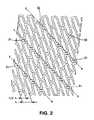
- FIG. 2is a plan view of the endoprosthesis of FIG. 1 ;
- FIG. 3shows alternative embodiments of interconnection elements to be in a device according to the invention
- FIG. 4is an enlarged view of an end portion of the endoprosthesis of FIG. 1 ;
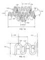
- FIG. 5shows an isometric view of a second embodiment of an expandable intraluminal endoprosthesis in accordance with the present invention
- FIG. 6shows a plan view of the device of FIG. 5 in a unexpanded state
- FIG. 7is a plan view of the device of FIG. 5 in a expanded, deployed state.
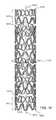
- FIG. 8is a three dimensional view of one embodiment of a stent according to the present invention in its unexpanded state
- FIG. 9is planar view of a flattened portion of the circumference of the stent in FIG. 8 ;
- FIG. 10is an enlarged portion of FIG. 9 ;
- FIG. 11is another planar view of a flattened portion of the circumference of a stent according to the present invention in its unexpanded state;
- FIG. 12is an enlarged view of a portion of FIG. 11 showing a first circumferential element of the stent
- FIG. 13is an enlarged view of a portion of FIG. 11 showing a second circumferential element of the stent
- FIG. 14is a planar view of a flattened portion of the stent in FIG. 8 showing a plurality of sets of helical segments propagating through the stent's body;
- FIG. 15is a planar view of a flattened endzone that may be employed in a stent of the present invention.
- FIG. 16is a planar view of a flattened portion of part of the endzone shown in FIG. 15 ;
- FIG. 17is a planar view of a flattened portion of an expandable stent according to the present invention, after the stent has been deployed in a lumen;
- FIG. 18is three dimensional view of an alternative embodiment of the present invention.
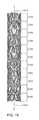
- FIG. 19is a three dimensional view of another stent according to the present invention.
- FIG. 20is a planar view of the stent shown in 19 ;
- FIG. 21is a detailed view of a portion of FIG. 20 ;
- FIG. 22is a detailed view of another portion of FIG. 20 .
- the present inventionis directed to an expandable stent, as well as a method of manufacturing the stent.
- FIG. 1gives an isometric view of an expandable intraluminal endoprosthesis according to a specific embodiment of the present invention.
- the endoprosthesishereinafter briefly referred to as stent, comprises a tubular member 1 which has been separated out of a tubular body of a suitable bio-compatible material.
- a suitable bio-compatible materialfor instance high grade stainless steel (SST), a nickel-titanium based alloy referred to as Nitinol (NiTi), several cobalt based alloys and a Niobium-Titanium (NbTi) based alloy qualify.
- the latter materialmay be chosen because of its excellent mechanical strength, corrosion resistance and radiopaque fluoroscopic signature.
- the tubular member 1is drawn with a first diameter d which permits delivery of the member into a lumen of a body passageway, particularly a blood vessel.
- the member 1is capable of acquiring a second, expanded and deformed diameter upon the application of a radially outwardly extending force from its interior, usually by means of a balloon-catheter.
- This second diameteris variable and dependent on the amount of force applied.
- the memberwill show a certain amount of recoil which means that the device will retract more or less after the balloon has been evacuated.
- the second diameterwill be slightly smaller than the diameter to which the stent has been expanded. Nevertheless the tubular member may be expanded and deformed to expand the lumen of the body passageway to again assure an undisturbed flow through the lumen, like a blood vessel.
- the wall of the stentcomprises a substantially continuous structure which in this example consists of a continuous filament which has been cut out from the tube wall in a substantially helical fashion with a width between about 0.10 and 0.17 mm. This may be done by means of laser cutting, electrochemical etching, electromechanical discharge or any other suitable technique preferably followed by a suitable surface treatment, like etching to deburr and or round off possible sharp edges.
- a tubular body with an internal diameter of about 3.0 mm, a wall thickness of about 1.0 mm and a length of about 30 mmhas been chosen as a starting material.
- other dimensionsare likewise feasible within the scope of the present invention.
- the filament-structurecomprises a number of undulations 2 which are mutually staggered in helical pattern advancing around a central longitudinal axis of the device.
- connection elements 31 , 32which are entirely integral with the undulations thereby connected, as they are cut altogether from one and the same tubular body.
- connection elements 31 to subsequent turnsare radially shifted by about half undulation pitch distance 1 ⁇ 2L to form a helical pattern X-X, Y-Y.
- these patternswill expand to a helically turning spines which form a primary framework or scaffolding lattice of the deployed stent.
- This frameworksupports the vessel wall highly uniformly throughout the device and moreover is capable of withstanding substantial inwardly directed radial forces. This capability of the framework is referred to as its hoop strength.
- the lower drawing part of FIG. 2shows a part of a central modular portion of the device in which successive turns of the filament are interconnected by means of only two connection elements 31 , which are shifted about 180° with respect to one another, while the upper part shows an end portion of the device together with an intermediate portion in which three equally spaced connection elements 31 , 32 interconnect adjacent undulations from successive turns of the filament with each other.
- the parent scaffolding lattice of the deployed devicewill be composed of only one helically advancing spine within the central region and will comprise two helically revolving spines within the other regions.
- connection element 31 and 32two kinds are used, denoted 31 and 32 respectively.
- Both types of connection elementsfeature a strut 3 which is S-shaped and diagonally interconnects opposite sides of adjacent undulations from successive turns of the filament in a helical direction different to that of the staggered undulations themselves, see also FIG. 3E .
- These strutswill be referred to as major struts as they are part of the lattice spines described hereinbefore.
- the strutswill be referred to as major struts as they are part of the lattice spines described hereinbefore.
- the second type of interconnection element 32moreover features a second, S-shaped diagonal 4 strut intersecting the first one, see also FIG. 3D .
- connection element of the second kind 32will first start to rotate around its central axis once the stent is being deployed with only a limited force being exerted axially in the diagonal 3 of the connection element. Only after the first diagonal 3 has become fully in line with the sides of the undulations it interconnects, does it have to withstand the entire force axially.
- This incorporated slack and stress reliefallows thinner strut width and filament width over the lattice legs which can be useful for decreasing the radio-opacity at this area as well as improves its unexpanded, crimped as well as deployed, expanded flexibility.
- the support area covered by connection elements of this second kindwill not decrease much upon deployment of the device. As a result a larger “scaffolding footprint” will remain after deployment compared to any of the other types of connection elements shown which all will stretch substantially upon deployment leaving only the thin major strut 3 as “scaffolding footprint”.
- connection elements depicted in the drawingother shapes are also feasible, as the invention imposes hardly any limitation of the design of any part of the device including the shape of the interconnections used. Examples of other shapes which could advantageously be used in a device according to the invention are shown in FIGS. 3A 3 G.
- the connection elements of FIGS. 3A 3 Cmerely comprise a straight strut 3 connection adjacent undulations, whereas the main strut 3 of the connection elements shown in FIGS. 3D 3 F have a clearly S-curved shape.
- This shapeintroduces more slack and expandability in the structure. The longer this segment, the more slack and expandability there is in the structure and especially in the spinal ladder created by these connection elements in the eventual deployed device.
- a simple formulacan be derived from the expanded state, defining the relative increase of the strut length and the effect it has on the expansion range of the device.
- the major strut 3i.e. the strut eventually forming part of the parent scaffold or framework of the device once it is deployed, is indicated in FIG. 3 by a dotted hatch.
- this strut as well as the undulation sides which it interconnectsare given a first filament width w.sub.1 sufficiently large to withstand the axial forces imposed thereon during expansion of the device, whilst the other undulation sides and if applicable the other strut of the connection element are given a second filament width w.sub.2, at least locally, to gain flexibility and decrease radio-opacity.
- the filament widthis modified in the central portion of the device to improve its overall flexibility such that a first filament width w.sub.1 of approximately 0.14 mm is taken whereas the second filament width w.sub.1 is reduced to about 0.11 mm.
- the amplitudes of the undulations within such pairmay be adapted to fill the gap which would otherwise remain due to the inevitable length of a connection element elsewhere in the structure. This is for instance apparent from FIG. 2 where all adjacent peaks and valleys of pairs of undulations out of successive turns which are not interconnected nevertheless adjoin one another. This is a result of the adapting the amplitude of at least one of the undulations within such pair of undulations.
- both, the peak and the valleyhave an increased amplitude, that only one of those parts is enlarged, the other part remaining unchanged, or even that either the peak or the valley has a increased amplitude while the other part has a decreased amplitude.
- the designerhas full freedom to tailor the stent design to allow optimal behaviour of the stent in its unexpanded state, expanded and/or transitional state.
- the end portion of the deviceends substantially transverse to the central axis of the device in order to avoid a cantilever usually associated with a helix shape which could otherwise harm the wall of the lumen through which the stent is navigated.
- This end portionis shown in more detail in FIG. 4 .
- Its particular shapeis obtained by gradually decreasing the amplitude in the last few undulations and adapting their mutual pitch. Due to the invention this may be done without introducing any stress in the device as the filament is simply cut in the desired pattern.
- the deviating amplitudes and mutual pitchare best recognized from the plan view of FIG. 2 .
- the end modulesexhibit a greater stent-to-vessel ratio than the central and intermediate portions due to the increased metal-to-surface-area in the expanded configuration.
- the more complex structure of the end portionsmoreover give rise to a greater amount of foreshortening upon expansion, thus producing a more dense pattern yielding additional stent-to-vessel ratio.
- FIGS. 5 7A second embodiment of the device according to the invention is depicted in FIGS. 5 7 .
- This devicecomprises a tubular body 1 and has been manufactured using similar techniques as in the first embodiment, although in this case a more complicated structure has been created consisting of more than just a single, wrapped filament.
- the structure of the deviceis composed of a substantially helical pattern of mutually staggered undulations 2 , with connection elements 33 interconnecting some undulations from successive turns of said pattern.
- the connection elements within this structureprimarily comprise two intersecting struts like the type reflected in FIG. 3D .
- connection elements 33 to subsequent turns of said patternare shifted by about a full pitch distance.
- a full undulation 25will link said connection elements 33 to one another and as such creates an elongated member 25 in between the connection elements 33 .
- Said elongated member formed by an intermediate undulationcomprises a S-curved bent and is longer than the linear distance between the interconnection elements thereby linked to each other, at least in the crimped state shown in FIGS. 5 and 6 . This imparts additional slack and considerable expandability to the spinal ladders which are formed by such a series of linked connection elements in the deployed state shown in FIG. 7 .
- the orientation of the S-curved bents in said elongated members 25which is substantially parallel to the longitudinal axis of the body at least in the crimped state shown in FIGS. 5 and 6 , allows the member 25 to uniformly expand in a direction which is substantially perpendicular to said axis. This prevents the device from twisting and turning on the balloon-catheter once it is being expanded.
- said series of interlinked connection elements mutually shifted by a pitch distanceform further substantially helically advancing patterns within the structure.
- these further helically revolving patternswill mature to helical spines running through the structure once it is being expanded, see FIG. 7 .
- These additional spineshowever run in a different direction than the spines created by the undulations, indicated by the straight lines in FIG. 7 , which results in an eventual structure with a considerable hoop strength in combination with an excellent unexpanded and deployed flexibility.
- these aspectsmay be once more tailored throughout the device to fit the best overall characteristics in each portion of the device.
- the filament width as well undulation shapesmay be varied and adapted to suit specific required characteristics besides the flexibility and stent-to-vessel ratio.
- the foreshortening of the devicei.e. the amount of length reduction upon expansion from the crimped to the deployed state of the device, its degree of recoil, its hoop strength as well as it radio-opacity may be so varied and adapted.
- the present inventionprovides the designer with the greatest amount of freedom conceivable.
- the elongated members interlinking a series of connections elements like in the second embodimentneed not coincide with undulations of the pattern and can be introduced in the structure as separate elements.
- These membersmoreover need not necessarily comprise a full S-curved bent or even any S-curved bent at all and may on the other hand consist of more than just one such bent. Also in this respect the designer has total freedom to tailor the device to his demands.
- the stentcomprises a generally cylindrical shaped main body section 1011 having a cylindrical axis 1005 and a wall thickness 1103 .
- the wall thickness 1103may optionally be uniform throughout the stent.
- the main body section 1011is comprised of a plurality of helical segments 1030 and 1040 and a plurality of main body cylindrical elements 1100 , each having cylindrical axes (not shown) that are collinear with the main body cylindrical axis 1005 .
- the main body cylindrical elements 1100are each comprised of circumferential elements 1050 that are joined together by the helical segments 1030 and 1040 to form individual cylinders 1100 .
- the stentmay also have a first endzone 1010 and a second endzone 1020 that straddle the body section 1011 .
- the endzones 1010 and 1020may advantageously provide the stent with square outer edges 1008 .
- the stentmay be manufactured from stainless steel, or other suitable materials. In most embodiments, it is desirable that the material, or a portion of the material, be radiopaque and that the various segments that form the stent be contiguous. Although, in some embodiments, the various segments that make up the stent can be distinct elements that are joined together.
- the main body 1011may be formed in numerous ways.
- the body 1011may contain two or more first helical segment 1030 and 1040 that are generally parallel to each other. In some embodiments they may be opposite each other by 180 degrees.
- the first helical segments 1030 and 1040will be spaced equidistant along the circumference 1110 of the main body 1011 .
- the first helical segments 1030 and 1040are joined by a plurality of circumferential segments 1050 to form a plurality of main body cylindrical elements 1100 , which may be only generally cylindrically shaped.
- the circumferential segments 1050make up a majority of the circumference 1110 of each cylindrical element 1100 .
- the helical segments 1030 and 1040connect each cylindrical element 1100 to an adjacent cylindrical element 1100 to form the main body 1011 .
- the body of the stent 1011may comprise a plurality of main body cylindrical elements 1100 formed from first circumferential segments 1050 that are joined with second circumferential segments 1060 .
- the second circumferential segments 1060 of each cylindrical element 1100may be joined with second circumferential segments 1060 of adjacent cylindrical elements 1100 to form a plurality of first helical segments 1030 and 1040 in the main body 1011 . (See FIG. 9 ).
- Each first circumferential segment 1050may have a circumferential dimension 1055 and each second circumferential segments 1060 may have a circumferential dimension 1066 ′ (See FIG. 10 ).
- the first circumferential segment 1050may be an expandable segment formed from plurality of segments joined together to form a pattern.
- the patternsuch as the one shown in the FIGS. 8-10 , may be a repeating pattern that resembles a square wave form having curved peaks and valleys. Other patterns, both repeating and non-repeating, may be used.
- the first circumferential segments 1050may resemble a triangle wave form, a sinusoidal wave form, other repetitious patterns, or any pattern that enables the segment to expand when a radial force is exerted on the stent from the inside or collapse radially when an external crimping force is applied.
- the first circumferential elements 1050may have a filament width 1420 (see FIG. 11 ).
- the filament widthmay vary between 0.002 inches and 0.007 inches, but is preferably about 0.0050 inches. Other filament widths may be used depending on the parameters of the stent.
- the first circumferential elements 1050comprise linear portions 1320 and curved portions 1328 that join the linear portions 1320 together to form a repeating pattern.
- the linear portion 1320may be parallel to the cylindrical axis of the stent. In other embodiments, the linear portion 1320 lies at an angle of between 0-45 degrees with respect to the cylindrical axis.
- the first circumferential segment 1050has an amplitude 1350 and a period 1380 . In one embodiment the amplitude may range from 0.5 mm to 2.0 mm and the period may range from 0.5 mm to 2.0 mm. In some embodiments, the amplitude is less than the period. Other amplitudes and periods may be used depending on the overall stent design and performance constraints.
- the second circumferential element 1060which may be joined together in a helical pattern to form one or more helical segments 1030 or 1040 , may also take numerous forms, in addition to the form shown in FIG. 13 .
- the second circumferential element 1060comprises linear portions 1412 and curved portions 1414 having a filament width 1407 , and resembles generally an S-shaped structure.
- the second element circumferential segment 1060may have an angled portion 1417 attached to the linear portion 1412 at an end opposite that of the curved portion 1414 .
- the angled portionmay be oriented to form an angle ⁇ relative to the cylindrical axis of the stent 1005 in the range of 0-45 degrees.
- the preferable angle ⁇is about 10 degrees.
- the linear portions 1412 of the second circumferential element 1060lies at an angle ⁇ relative to the cylindrical axis of the stent, wherein ⁇ preferably ranges from 0 to 45 degrees.
- the linear portions 1412may, in some embodiments, form an angle ⁇ , relative to the cylindrical axis of the stent.
- ⁇may be approximately equal to the helical angle of the first helical segments 1030 and 1040 .
- the second circumferential elements 1060may have an amplitude 1300 (see FIGS.
- the preferred periodis about 0.82 mm and the preferred length of the linear portion 1412 is about 0.5 mm and the amplitude 1300 is about 0.38 mm.
- the amplitude of the second circumferential element 1060may be greater than, equal to, or less than the amplitude of the first circumferential element 1050 .
- the circumferential contributions of the first circumferential elements 1050 to the overall circumference of the main body 1011is greater than the circumferential contribution of the second circumferential element 1060 , in terms of either circumferential length or circumferential cylindrical surface area.
- the stentmay have an overall outer surface area of about 0.029 square inches.
- the stentmay have a main body 1011 comprised of two or more first helical segments 1030 and 1040 , as well as two or more second helical segments 1200 and 1210 .
- the first and second helical segments 1030 , 1040 and 1200 , 1210are joined together to form a generally cylindrically shaped body 1011 .
- the first and second helical segmentsmay share a common connecting element 1250 .
- the common connecting element 1250may be H-shaped and the two generally parallel linear portions of the H-shaped connecting segment 1250 may form an angle ⁇ relative to the axis 1005 . (See FIG. 13 ).
- ⁇may, in one embodiment, be about 14 degrees.
- the first helical segments 1030 and 1040 and second helical segments 1200 and 1210may have different pitches, i.e. number of spirals per unit length, which results in the first and second helical segments as having different helical angles ( ⁇ and ⁇ , respectively) i.e. the angle of the helical segment relative to the cylindrical axis 105 of the stent.
- the second helical segments 1200 and 1210have a pitch approximately twice that of the first helical segments.
- ⁇may vary from 0 to 45 degrees and is preferably about 40 degrees and ⁇ is preferably about twice ⁇ .
- the angle ⁇may range from 0 to 90 degrees to the circumference 1110 of each cylindrical element 1100 .
- the helical segments 1030 , 1040are circumferentially expandable (i.e. they expand along the circumference of the stent) and may be formed from a plurality of circumferential elements 1060 that in turn are made up of linear 1412 and/or curved 1414 segments (see FIG. 13 ) that each have a filament width 1407 (see FIG. 13 ) that is less than the circumferential dimension 1066 of the circumferential element 1060 (see FIG. 10 ).
- each helical segment 1030 or 1040will make a total contribution to the circumference of each cylindrical element 1100 that is greater than the filament width 1407 .
- each helical segment 1030 or 1040may be greater than the circumferential contribution of the filament widths 1407 of the segments (e.g. 1412 and 1414 ) making up the circumferential elements 1060 that in turn make up the helical segments.
- the circumferential contribution of the helical segments 1030 and 1040 to the circumference 1110 of each cylindrical element 1100is more than just a function of the filament width 1407 , e.g., it may be a function of the geometry of the element 1060 .
- the geometry of the helical segments 1030 and 1040are a factor in determining their expandability.
- the helical segments 1200 , 1210are circumferentially expandable and may be comprised of other circumferential elements 1050 that are in turn comprised of linear 1320 and/or curved segments 1328 (see FIGS. 10 and 12 ) that have a filament width 1420 (see FIG. 11 ).
- the contribution of the helical segments 1200 , 1210 to the overall circumferential dimension 1110 of each cylindrical element 1100is greater than just the contribution of the filament widths 1420 of the individual segments 1320 and 1328 that make up the elements 1050 that in turn make up the helical segments 1200 , 1210 .
- the geometry of the elements 1050 making up the helical segments 1200 , 1210may be a more important factor in determining the circumferential contribution of the helical segments 1200 and 1210 to the overall stent circumference than the filament width 1420 .
- the circumference of the stent 1110 in its unexpanded state and the circumference 1105 when the stent is expandedare primarily functions of the geometry of the elements 1050 and 1060 that make up the helical segments 1030 , 1040 and 1200 , 1210 , respectively.
- endzones 1010 and 1020may employ endzones 1010 and 1020 .
- Stents that employ endzoneswill generally have two endzone regions straddling a central zone in the middle of the stent.
- the stentsmay also have a transition region between the endzone and the central zone.
- the transition regionserves to help smoothly transition between the expanded middle region and portions of the end of the stent that remain unexpanded after the stent is implanted.
- the size and characteristics of the transition regionare a function of the material and geometry of the stent.
- the transition range propertiesvary as a function of, among other things, the helical angle of the first helical segments, the number of curved segments located in the endzones, and the angle .epsilon. of the linear portions of the segments forming the endzones. (See e.g. FIG. 15 ).
- the endzones 1010 and 1020may take numerous forms.
- the endzonesmay be comprised of one or more rings 1017 .
- the rings 1017may be generally cylindrically shaped, and in some embodiments, right cylindrically shaped.
- the ringsare formed from linear segments 1028 joined together by curved segments 1029 to form a pattern.
- the patternwhich is preferably—but not necessarily—a repeating pattern may take numerous forms, including the one shown.
- the endzones 1010 and 1020may be comprised of a plurality of rings 1017 attached together.
- Struts 1015may be used to attach the rings together to form the endzone and to attach the endzone to the main body 1011 .
- the strutsin some embodiments, act as cantilever springs and there stiffness, which is a function of their width and thickness, may define bending properties of the stent along its cylindrical axis 1005 .
- the linear segments 1028 in the endzone 1010are oriented at an angle c relative to the cylindrical axis of the stent.
- the angle cis greater than 0 degrees.
- cmay range from 0 to 45 degrees and in still another embodiment is preferably about 10 degrees.
- the segments of the endzonemay have a filament width 1013 of between 0.002 and 0.007 inches.
- the repeating pattern of the endzonehas a period 1002 of about 0.027 inches and an amplitude 1021 of about 0.043 inches. Other values may be used. As is shown in FIG.
- the struts 1015which are but one way to attach the endzones 1010 and 1020 to the main body 1011 , may, in one embodiment have a width of between 0.002 inches and 0.08 inches and preferably the width does not exceed the wall thickness, which typically—but not necessarily ranges from about 0.002 to 0.008 inches.
- the stent of the present inventionmay, after insertion into a vessel, be expanded such that it plastically deforms from the unexpanded state to an expanded state having a diameter increase of about 400 to 500%, which results in a larger circumference 1105 .
- FIG. 18depicts the stent shown in FIG. 8 in an expanded state.
- the stent's outer diameterin one particular embodiment increases from 1.0 mm to 3.00 mm and maintains a stent-to-vessel ratio in the expanded state that is greater than on average 16%.
- FIGS. 19-22depict an endzoneless stent. Like the stent shown in FIG. 8 , the stent of FIGS. 19-22 comprises a plurality of adjacent cylindrical elements 1100 .
- the cylindrical elements 1100are formed from a plurality of first circumferential elements 1050 ′ and second circumferential elements 1060 .
- the first circumferential elements 1050 ′ of the stent in FIGS. 19-22are substantially identical to the second circumferential element 1060 except that they are rotated to have a different orientation.
- the circumferential elementsmay be generally S-shaped having a linear portion 1412 , a curved portion 1414 having a radius R, and an angled portion 1417 .
- Rmay vary widely depending on overall stent characteristics and in one embodiment varies between 0.001 and 0.02 inches and is preferably about 0.0083 inches.
- the angled portion 1417is spaced a distance 1499 from the linear portion. In one particular embodiment, the distance 1499 may vary from 0.002 to 0.020 inches and is preferably about 0.007 inches.
- the filament width 1407 of the elementsmay, in one embodiment, be about 0.13 mm.
- angle Kmay be generally S-shaped having a linear portion 1412 , a curved portion 1414 having a radius R, and an angled portion 1417 .
- the angle Kmay vary widely depending on overall stent characteristics and range of radial compression or expansion about the axis 5 .
- Adjacent cylindrical elements 1100are joined together by connecting first circumferential elements 1050 ′ in each cylindrical element 1100 with first circumferential elements 1050 ′ in an adjacent cylindrical element 1100 , such that the first circumferential elements 1050 ′ in adjacent cylindrical elements 1100 form helixes through the stent and such that second circumferential elements form helixes through the stent having an angle ⁇ relative to the axis 1005 .
- a connecting segment 1250(see FIG. 14 ) is used to connect first circumferential elements in adjacent cylindrical elements 1100 and to connect second circumferential elements 1060 in adjacent cylindrical elements 1100 .
- the connecting segmentconnects first circumferential elements 1050 ′ in each cylindrical element 1100 with two second circumferential elements 1060 in each cylindrical element 1100 .
- the individual cylindrical elements 1100are adjacent to each other and are located a distance 1666 apart. In one embodiment, the preferred may range between 0.002 and 0.020 inches, and is preferably about 0.009 inches.
- the above description of the stent of the present inventionis illustrative and not exhaustive. Various modifications may be made to the stent to change its overall characteristics without deviating from the scope and spirit of the invention as defined by the claims.
- the increasing the length of the linear segments and or increasing the arc of the second circumferential elements 1060will decrease the amount of radial force required to expand each circular section and will increase flexibility.
- Increasing the angle ⁇ of the second circumferential element 1060will: (i) increase the amount of radial force required for expansion, (ii) increase surface area, and (iii) decrease flexibility.
- various modificationsmay be made to the struts 1015 . (See FIG. 9 ).
- Increasing strut width and wall thicknesswill: (i) increase surface area, (ii) increase radial strength, (iii) increase pressure required to expand the stent radially, (iv) decrease flexibility, and, in the case of increased wall thickness, (v) increase radiopacity.
- the stent of the present inventionmay be manufactured in numerous ways.
- the stentmay be formed from a metallic tube by removing various portions of the tube's wall to form the patterns described herein.
- the resulting stentwill thus be formed from a single contiguous piece of material, eliminating the need for connecting various segments together.
- Material from the tube wallmay be removed using various techniques including laser (YAG laser for example), electrical discharge, chemical etching, metal cutting, a combination of these techniques, or other well known techniques. See e.g. U.S. Pat. Nos. 5,879,381 to Moriuchi et al. and 6,117,165 to Becker, which are hereby incorporated in their entirety by reference.
- the tube from which the stent is formedmay have an internal diameter of about 3.0 mm, a wall thickness of about 1.0 mm and a length of about 30 mm. Tubes having other dimensions may be used. In particular, the length may be adapted to that of the diseased part of the lumen in which the stent is to be placed. This may avoid using separate stents to cover the total diseased area.
Landscapes
- Health & Medical Sciences (AREA)
- Engineering & Computer Science (AREA)
- Biomedical Technology (AREA)
- Heart & Thoracic Surgery (AREA)
- Life Sciences & Earth Sciences (AREA)
- Cardiology (AREA)
- Oral & Maxillofacial Surgery (AREA)
- Transplantation (AREA)
- Physics & Mathematics (AREA)
- Vascular Medicine (AREA)
- Optics & Photonics (AREA)
- Animal Behavior & Ethology (AREA)
- General Health & Medical Sciences (AREA)
- Public Health (AREA)
- Veterinary Medicine (AREA)
- Media Introduction/Drainage Providing Device (AREA)
- Prostheses (AREA)
Abstract
Description
Claims (11)
Priority Applications (1)
| Application Number | Priority Date | Filing Date | Title |
|---|---|---|---|
| US12/178,915US8382820B2 (en) | 1997-06-13 | 2008-07-24 | Stent having helical elements |
Applications Claiming Priority (10)
| Application Number | Priority Date | Filing Date | Title |
|---|---|---|---|
| EP97201799AEP0890346A1 (en) | 1997-06-13 | 1997-06-13 | Expandable intraluminal endoprosthesis |
| EP97201799 | 1997-06-13 | ||
| EP98201446 | 1998-05-06 | ||
| EP98201446AEP0884029B1 (en) | 1997-06-13 | 1998-05-06 | Expandable intraluminal endoprosthesis |
| US09/094,402US6117165A (en) | 1997-06-13 | 1998-06-10 | Expandable intraluminal endoprosthesis |
| US09/511,481US7108714B1 (en) | 1997-06-13 | 2000-02-23 | Expandable intraluminal endoprosthesis |
| US25468800P | 2000-12-11 | 2000-12-11 | |
| US10/014,705US7329277B2 (en) | 1997-06-13 | 2001-12-11 | Stent having helical elements |
| US12/027,382US8486133B2 (en) | 1997-06-13 | 2008-02-07 | Stent having helical elements |
| US12/178,915US8382820B2 (en) | 1997-06-13 | 2008-07-24 | Stent having helical elements |
Related Parent Applications (1)
| Application Number | Title | Priority Date | Filing Date |
|---|---|---|---|
| US12/027,382ContinuationUS8486133B2 (en) | 1997-06-13 | 2008-02-07 | Stent having helical elements |
Publications (2)
| Publication Number | Publication Date |
|---|---|
| US20080288053A1 US20080288053A1 (en) | 2008-11-20 |
| US8382820B2true US8382820B2 (en) | 2013-02-26 |
Family
ID=26146599
Family Applications (20)
| Application Number | Title | Priority Date | Filing Date |
|---|---|---|---|
| US09/511,481Expired - LifetimeUS7108714B1 (en) | 1997-06-13 | 2000-02-23 | Expandable intraluminal endoprosthesis |
| US10/071,071Expired - LifetimeUS6821292B2 (en) | 1997-06-13 | 2002-02-08 | Crimpable intraluminal endoprosthesis having helical elements |
| US10/390,100AbandonedUS20030149474A1 (en) | 1997-06-13 | 2003-03-17 | Expandable intraluminal endoprosthesis |
| US10/993,380AbandonedUS20050090894A1 (en) | 1997-06-13 | 2004-11-19 | Crimpable intraluminal endoprosthesis having helical elements |
| US11/523,726AbandonedUS20070203570A1 (en) | 1997-06-13 | 2006-09-19 | Expandable intraluminal endoprosthesis |
| US12/027,382Expired - Fee RelatedUS8486133B2 (en) | 1997-06-13 | 2008-02-07 | Stent having helical elements |
| US12/178,387AbandonedUS20080288050A1 (en) | 1997-06-13 | 2008-07-23 | Stent having helical elements |
| US12/178,396AbandonedUS20080288051A1 (en) | 1997-06-13 | 2008-07-23 | Stent having helical elements |
| US12/178,883AbandonedUS20080281406A1 (en) | 1997-06-13 | 2008-07-24 | Stent having helical elements |
| US12/178,906Expired - Fee RelatedUS8968385B2 (en) | 1997-06-13 | 2008-07-24 | Stent having helical elements |
| US12/178,898AbandonedUS20080294244A1 (en) | 1997-06-13 | 2008-07-24 | Stent having helical elements |
| US12/178,895AbandonedUS20080294243A1 (en) | 1997-06-13 | 2008-07-24 | Stent having helical elements |
| US12/178,909AbandonedUS20080288052A1 (en) | 1997-06-13 | 2008-07-24 | Stent having helical elements |
| US12/178,889AbandonedUS20080281407A1 (en) | 1997-06-13 | 2008-07-24 | Stent having helical elements |
| US12/178,915Expired - Fee RelatedUS8382820B2 (en) | 1997-06-13 | 2008-07-24 | Stent having helical elements |
| US12/196,761AbandonedUS20080319537A1 (en) | 1997-06-13 | 2008-08-22 | Stent having helical elements |
| US12/243,392Expired - Fee RelatedUS7682384B2 (en) | 1997-06-13 | 2008-10-01 | Stent with helical elements |
| US12/727,567Expired - Fee RelatedUS8372135B2 (en) | 1997-06-13 | 2010-03-19 | Stent having helical elements |
| US12/878,341Expired - Fee RelatedUS7942922B2 (en) | 1997-06-13 | 2010-09-09 | Stent having helical elements |
| US12/878,232Expired - Fee RelatedUS7967852B2 (en) | 1997-06-13 | 2010-09-09 | Stent having helical elements |
Family Applications Before (14)
| Application Number | Title | Priority Date | Filing Date |
|---|---|---|---|
| US09/511,481Expired - LifetimeUS7108714B1 (en) | 1997-06-13 | 2000-02-23 | Expandable intraluminal endoprosthesis |
| US10/071,071Expired - LifetimeUS6821292B2 (en) | 1997-06-13 | 2002-02-08 | Crimpable intraluminal endoprosthesis having helical elements |
| US10/390,100AbandonedUS20030149474A1 (en) | 1997-06-13 | 2003-03-17 | Expandable intraluminal endoprosthesis |
| US10/993,380AbandonedUS20050090894A1 (en) | 1997-06-13 | 2004-11-19 | Crimpable intraluminal endoprosthesis having helical elements |
| US11/523,726AbandonedUS20070203570A1 (en) | 1997-06-13 | 2006-09-19 | Expandable intraluminal endoprosthesis |
| US12/027,382Expired - Fee RelatedUS8486133B2 (en) | 1997-06-13 | 2008-02-07 | Stent having helical elements |
| US12/178,387AbandonedUS20080288050A1 (en) | 1997-06-13 | 2008-07-23 | Stent having helical elements |
| US12/178,396AbandonedUS20080288051A1 (en) | 1997-06-13 | 2008-07-23 | Stent having helical elements |
| US12/178,883AbandonedUS20080281406A1 (en) | 1997-06-13 | 2008-07-24 | Stent having helical elements |
| US12/178,906Expired - Fee RelatedUS8968385B2 (en) | 1997-06-13 | 2008-07-24 | Stent having helical elements |
| US12/178,898AbandonedUS20080294244A1 (en) | 1997-06-13 | 2008-07-24 | Stent having helical elements |
| US12/178,895AbandonedUS20080294243A1 (en) | 1997-06-13 | 2008-07-24 | Stent having helical elements |
| US12/178,909AbandonedUS20080288052A1 (en) | 1997-06-13 | 2008-07-24 | Stent having helical elements |
| US12/178,889AbandonedUS20080281407A1 (en) | 1997-06-13 | 2008-07-24 | Stent having helical elements |
Family Applications After (5)
| Application Number | Title | Priority Date | Filing Date |
|---|---|---|---|
| US12/196,761AbandonedUS20080319537A1 (en) | 1997-06-13 | 2008-08-22 | Stent having helical elements |
| US12/243,392Expired - Fee RelatedUS7682384B2 (en) | 1997-06-13 | 2008-10-01 | Stent with helical elements |
| US12/727,567Expired - Fee RelatedUS8372135B2 (en) | 1997-06-13 | 2010-03-19 | Stent having helical elements |
| US12/878,341Expired - Fee RelatedUS7942922B2 (en) | 1997-06-13 | 2010-09-09 | Stent having helical elements |
| US12/878,232Expired - Fee RelatedUS7967852B2 (en) | 1997-06-13 | 2010-09-09 | Stent having helical elements |
Country Status (3)
| Country | Link |
|---|---|
| US (20) | US7108714B1 (en) |
| EP (1) | EP0884029B1 (en) |
| JP (2) | JP4704528B2 (en) |
Cited By (7)
| Publication number | Priority date | Publication date | Assignee | Title |
|---|---|---|---|---|
| US9173977B2 (en) | 2010-04-19 | 2015-11-03 | Angioscore, Inc. | Coating formulations for scoring or cutting balloon catheters |
| US9351756B2 (en) | 2010-09-21 | 2016-05-31 | Angioscore, Inc. | Method and system for treating valve stenosis |
| US9375328B2 (en) | 2001-11-09 | 2016-06-28 | Angioscore, Inc. | Balloon catheter with non-deployable stent |
| US9586031B2 (en) | 2005-05-11 | 2017-03-07 | Angioscore, Inc. | Methods and systems for delivering substances into luminal walls |
| US9962529B2 (en) | 2003-01-21 | 2018-05-08 | Angioscore, Inc. | Apparatus and methods for treating hardened vascular lesions |
| US10086178B2 (en) | 2001-11-09 | 2018-10-02 | Angioscore, Inc. | Balloon catheter with non-deployable stent |
| US10117668B2 (en) | 2013-10-08 | 2018-11-06 | The Spectranetics Corporation | Balloon catheter with non-deployable stent having improved stability |
Families Citing this family (227)
| Publication number | Priority date | Publication date | Assignee | Title |
|---|---|---|---|---|
| US7204848B1 (en)* | 1995-03-01 | 2007-04-17 | Boston Scientific Scimed, Inc. | Longitudinally flexible expandable stent |
| US5755682A (en) | 1996-08-13 | 1998-05-26 | Heartstent Corporation | Method and apparatus for performing coronary artery bypass surgery |
| US7329277B2 (en) | 1997-06-13 | 2008-02-12 | Orbusneich Medical, Inc. | Stent having helical elements |
| EP0884029B1 (en) | 1997-06-13 | 2004-12-22 | Gary J. Becker | Expandable intraluminal endoprosthesis |
| US6013091A (en)* | 1997-10-09 | 2000-01-11 | Scimed Life Systems, Inc. | Stent configurations |
| US6129755A (en)* | 1998-01-09 | 2000-10-10 | Nitinol Development Corporation | Intravascular stent having an improved strut configuration |
| US6503271B2 (en) | 1998-01-09 | 2003-01-07 | Cordis Corporation | Intravascular device with improved radiopacity |
| US6395019B2 (en) | 1998-02-09 | 2002-05-28 | Trivascular, Inc. | Endovascular graft |
| US6755856B2 (en) | 1998-09-05 | 2004-06-29 | Abbott Laboratories Vascular Enterprises Limited | Methods and apparatus for stenting comprising enhanced embolic protection, coupled with improved protection against restenosis and thrombus formation |
| US7815763B2 (en)* | 2001-09-28 | 2010-10-19 | Abbott Laboratories Vascular Enterprises Limited | Porous membranes for medical implants and methods of manufacture |
| US7887578B2 (en) | 1998-09-05 | 2011-02-15 | Abbott Laboratories Vascular Enterprises Limited | Stent having an expandable web structure |
| US6682554B2 (en) | 1998-09-05 | 2004-01-27 | Jomed Gmbh | Methods and apparatus for a stent having an expandable web structure |
| US6254564B1 (en) | 1998-09-10 | 2001-07-03 | Percardia, Inc. | Left ventricular conduit with blood vessel graft |
| US6641610B2 (en) | 1998-09-10 | 2003-11-04 | Percardia, Inc. | Valve designs for left ventricular conduits |
| AU6384699A (en) | 1998-09-10 | 2000-04-03 | Percardia, Inc. | Tmr shunt |
| JP2002524196A (en) | 1998-09-10 | 2002-08-06 | パーカーディア,インコーポレイティド | Transmyocardial shunt for left ventricular revascularization and its mounting mechanism |
| US6290728B1 (en) | 1998-09-10 | 2001-09-18 | Percardia, Inc. | Designs for left ventricular conduit |
| US6042597A (en) | 1998-10-23 | 2000-03-28 | Scimed Life Systems, Inc. | Helical stent design |
| US8382821B2 (en) | 1998-12-03 | 2013-02-26 | Medinol Ltd. | Helical hybrid stent |
| US20040267349A1 (en) | 2003-06-27 | 2004-12-30 | Kobi Richter | Amorphous metal alloy medical devices |
| US6660030B2 (en) | 1998-12-11 | 2003-12-09 | Endologix, Inc. | Bifurcation graft deployment catheter |
| EP1027870B1 (en)* | 1999-01-12 | 2005-03-30 | Orbus Medical Technologies, Inc. | Expandable intraluminal endoprosthesis |
| EP1020166A1 (en)* | 1999-01-12 | 2000-07-19 | Orbus Medical Technologies, Inc. | Expandable intraluminal endoprosthesis |
| US6355057B1 (en)† | 1999-01-14 | 2002-03-12 | Medtronic, Inc. | Staggered endoluminal stent |
| US8034100B2 (en) | 1999-03-11 | 2011-10-11 | Endologix, Inc. | Graft deployment system |
| US6261316B1 (en) | 1999-03-11 | 2001-07-17 | Endologix, Inc. | Single puncture bifurcation graft deployment system |
| US6409697B2 (en) | 1999-05-04 | 2002-06-25 | Heartstent Corporation | Transmyocardial implant with forward flow bias |
| FR2793673B1 (en)* | 1999-05-18 | 2001-10-12 | Jean Marie Lefebvre | TUBULAR STENT TYPE WITH LOW CRUSHING RESISTANCE |
| US6638237B1 (en) | 1999-08-04 | 2003-10-28 | Percardia, Inc. | Left ventricular conduits and methods for delivery |
| US7033372B1 (en) | 1999-08-04 | 2006-04-25 | Percardia, Inc. | Corkscrew reinforced left ventricle to coronary artery channel |
| US6605053B1 (en) | 1999-09-10 | 2003-08-12 | Percardia, Inc. | Conduit designs and related methods for optimal flow control |
| FR2799363B1 (en) | 1999-10-11 | 2001-11-30 | Braun Celsa Sa | MEDICAL IMPLANT IN MEANDRES IN ZIGZAG |
| US8088060B2 (en) | 2000-03-15 | 2012-01-03 | Orbusneich Medical, Inc. | Progenitor endothelial cell capturing with a drug eluting implantable medical device |
| US9522217B2 (en) | 2000-03-15 | 2016-12-20 | Orbusneich Medical, Inc. | Medical device with coating for capturing genetically-altered cells and methods for using same |
| US6423091B1 (en)* | 2000-05-16 | 2002-07-23 | Cordis Corporation | Helical stent having flat ends |
| JP2003533335A (en)* | 2000-05-22 | 2003-11-11 | オーバス メディカル テクノロジーズ インク. | Self-expanding stent |
| US20020032478A1 (en) | 2000-08-07 | 2002-03-14 | Percardia, Inc. | Myocardial stents and related methods of providing direct blood flow from a heart chamber to a coronary vessel |
| US7402173B2 (en) | 2000-09-18 | 2008-07-22 | Boston Scientific Scimed, Inc. | Metal stent with surface layer of noble metal oxide and method of fabrication |
| US7101391B2 (en) | 2000-09-18 | 2006-09-05 | Inflow Dynamics Inc. | Primarily niobium stent |
| JP2004521720A (en)* | 2000-12-11 | 2004-07-22 | オーバス メディカル テクノロジーズ インク. | Stent with helical component |
| US6976990B2 (en) | 2001-01-25 | 2005-12-20 | Percardia, Inc. | Intravascular ventriculocoronary bypass via a septal passageway |
| US8038708B2 (en) | 2001-02-05 | 2011-10-18 | Cook Medical Technologies Llc | Implantable device with remodelable material and covering material |
| WO2002091958A1 (en)* | 2001-02-09 | 2002-11-21 | Orbus Medical Technologies Inc. | Crimpable intraluminal endoprosthesis having helical elements |
| US6679911B2 (en)* | 2001-03-01 | 2004-01-20 | Cordis Corporation | Flexible stent |
| US6740114B2 (en) | 2001-03-01 | 2004-05-25 | Cordis Corporation | Flexible stent |
| US6790227B2 (en) | 2001-03-01 | 2004-09-14 | Cordis Corporation | Flexible stent |
| AU784552B2 (en) | 2001-03-02 | 2006-05-04 | Cardinal Health 529, Llc | Flexible stent |
| DE10118944B4 (en) | 2001-04-18 | 2013-01-31 | Merit Medical Systems, Inc. | Removable, essentially cylindrical implants |
| US20050021123A1 (en) | 2001-04-30 | 2005-01-27 | Jurgen Dorn | Variable speed self-expanding stent delivery system and luer locking connector |
| AU2002320456A1 (en) | 2001-07-26 | 2003-02-17 | Alveolus Inc. | Removable stent and method of using the same |
| DE10154163A1 (en) | 2001-11-03 | 2003-05-22 | Advanced Med Tech | Device for straightening and stabilizing the spine |
| US7147661B2 (en) | 2001-12-20 | 2006-12-12 | Boston Scientific Santa Rosa Corp. | Radially expandable stent |
| JP4331610B2 (en) | 2001-12-20 | 2009-09-16 | トリバスキュラー2,インコーポレイティド | Advanced endovascular graft |
| US7537607B2 (en)* | 2001-12-21 | 2009-05-26 | Boston Scientific Scimed, Inc. | Stent geometry for improved flexibility |
| US6949118B2 (en) | 2002-01-16 | 2005-09-27 | Percardia, Inc. | Encased implant and methods |
| US7008397B2 (en) | 2002-02-13 | 2006-03-07 | Percardia, Inc. | Cardiac implant and methods |
| AU2003239369A1 (en)* | 2002-05-06 | 2003-11-17 | Abbott Laboratories | Endoprosthesis for controlled contraction and expansion |
| US7128756B2 (en)* | 2002-05-08 | 2006-10-31 | Abbott Laboratories | Endoprosthesis having foot extensions |
| US8080052B2 (en)* | 2002-06-28 | 2011-12-20 | Cordis Corporation | Stent with diagonal flexible connecting links |
| US7326219B2 (en) | 2002-09-09 | 2008-02-05 | Wilk Patent Development | Device for placing transmyocardial implant |
| US7223283B2 (en)* | 2002-10-09 | 2007-05-29 | Boston Scientific Scimed, Inc. | Stent with improved flexibility |
| US7527644B2 (en) | 2002-11-05 | 2009-05-05 | Alveolus Inc. | Stent with geometry determinated functionality and method of making the same |
| US7959671B2 (en) | 2002-11-05 | 2011-06-14 | Merit Medical Systems, Inc. | Differential covering and coating methods |
| US7875068B2 (en) | 2002-11-05 | 2011-01-25 | Merit Medical Systems, Inc. | Removable biliary stent |
| US7637942B2 (en) | 2002-11-05 | 2009-12-29 | Merit Medical Systems, Inc. | Coated stent with geometry determinated functionality and method of making the same |
| FR2846520B1 (en)* | 2002-11-06 | 2006-09-29 | Roquette Freres | USE OF MALTODEXTRINS BRANCHED AS BLEACHES OF GRANULATION |
| US7901448B2 (en)* | 2002-12-24 | 2011-03-08 | Novostent Corporation | Vascular prothesis having interdigitating edges and methods of use |
| US7316710B1 (en)* | 2002-12-30 | 2008-01-08 | Advanced Cardiovascular Systems, Inc. | Flexible stent |
| US20070239251A1 (en)* | 2002-12-31 | 2007-10-11 | Abbott Cardiovascular Systems Inc. | Flexible stent |
| US7717952B2 (en) | 2003-04-24 | 2010-05-18 | Cook Incorporated | Artificial prostheses with preferred geometries |
| US7658759B2 (en) | 2003-04-24 | 2010-02-09 | Cook Incorporated | Intralumenally implantable frames |
| US7625399B2 (en)* | 2003-04-24 | 2009-12-01 | Cook Incorporated | Intralumenally-implantable frames |
| AU2004233848B2 (en) | 2003-04-24 | 2010-03-04 | Cook Medical Technologies Llc | Artificial valve prosthesis with improved flow dynamics |
| US7625398B2 (en)* | 2003-05-06 | 2009-12-01 | Abbott Laboratories | Endoprosthesis having foot extensions |
| US7625401B2 (en) | 2003-05-06 | 2009-12-01 | Abbott Laboratories | Endoprosthesis having foot extensions |
| US9155639B2 (en) | 2009-04-22 | 2015-10-13 | Medinol Ltd. | Helical hybrid stent |
| US9039755B2 (en)* | 2003-06-27 | 2015-05-26 | Medinol Ltd. | Helical hybrid stent |
| US20050182474A1 (en)* | 2004-02-13 | 2005-08-18 | Medtronic Vascular, Inc. | Coated stent having protruding crowns and elongated struts |
| EP1740219B1 (en) | 2004-04-30 | 2015-03-04 | OrbusNeich Medical, Inc. | Medical device with coating for capturing genetically-altered cells and methods of using same |
| US7763064B2 (en)* | 2004-06-08 | 2010-07-27 | Medinol, Ltd. | Stent having struts with reverse direction curvature |
| US7763065B2 (en) | 2004-07-21 | 2010-07-27 | Reva Medical, Inc. | Balloon expandable crush-recoverable stent device |
| US7894174B2 (en)* | 2004-08-23 | 2011-02-22 | Monolithic Power Systems, Inc. | Method and apparatus for fault detection scheme for cold cathode fluorescent lamp (CCFL) integrated circuits |
| US20060058869A1 (en)* | 2004-09-14 | 2006-03-16 | Vascular Architects, Inc., A Delaware Corporation | Coiled ladder stent |
| US7887579B2 (en) | 2004-09-29 | 2011-02-15 | Merit Medical Systems, Inc. | Active stent |
| US8292944B2 (en) | 2004-12-17 | 2012-10-23 | Reva Medical, Inc. | Slide-and-lock stent |
| DE102005003632A1 (en) | 2005-01-20 | 2006-08-17 | Fraunhofer-Gesellschaft zur Förderung der angewandten Forschung e.V. | Catheter for the transvascular implantation of heart valve prostheses |
| JP5523700B2 (en) | 2005-04-04 | 2014-06-18 | フレキシブル ステンティング ソリューションズ,インク. | Flexible stent |
| US7731654B2 (en) | 2005-05-13 | 2010-06-08 | Merit Medical Systems, Inc. | Delivery device with viewing window and associated method |
| EP2364676B1 (en)* | 2005-06-30 | 2018-12-19 | Abbott Laboratories | Endoprosthesis having foot extensions |
| US7637939B2 (en)* | 2005-06-30 | 2009-12-29 | Boston Scientific Scimed, Inc. | Hybrid stent |
| KR100633020B1 (en)* | 2005-07-15 | 2006-10-11 | 주식회사 스텐다드싸이텍 | Stents and how to make them |
| US8923972B2 (en)* | 2005-07-25 | 2014-12-30 | Vascular Dynamics, Inc. | Elliptical element for blood pressure reduction |
| US9642726B2 (en) | 2005-07-25 | 2017-05-09 | Vascular Dynamics, Inc. | Devices and methods for control of blood pressure |
| US20110077729A1 (en)* | 2009-09-29 | 2011-03-31 | Vascular Dynamics Inc. | Devices and methods for control of blood pressure |
| US9592136B2 (en) | 2005-07-25 | 2017-03-14 | Vascular Dynamics, Inc. | Devices and methods for control of blood pressure |
| US9125732B2 (en) | 2005-07-25 | 2015-09-08 | Vascular Dynamics, Inc. | Devices and methods for control of blood pressure |
| WO2010035271A1 (en)* | 2008-09-26 | 2010-04-01 | Vascular Dynamics Inc. | Devices and methods for control of blood pressure |
| US7914574B2 (en) | 2005-08-02 | 2011-03-29 | Reva Medical, Inc. | Axially nested slide and lock expandable device |
| US9149378B2 (en) | 2005-08-02 | 2015-10-06 | Reva Medical, Inc. | Axially nested slide and lock expandable device |
| ATE459312T1 (en) | 2005-08-17 | 2010-03-15 | Bard Inc C R | VARIABLE SPEED STENT DELIVERY SYSTEM |
| US8956400B2 (en)* | 2005-10-14 | 2015-02-17 | Flexible Stenting Solutions, Inc. | Helical stent |
| US7404823B2 (en) | 2005-10-31 | 2008-07-29 | Boston Scientific Scimed, Inc. | Stent configurations |
| US7381217B2 (en) | 2005-12-23 | 2008-06-03 | Boston Scientific Scimed, Inc. | Serpentine stent pattern |
| US8808346B2 (en) | 2006-01-13 | 2014-08-19 | C. R. Bard, Inc. | Stent delivery system |
| US11026822B2 (en) | 2006-01-13 | 2021-06-08 | C. R. Bard, Inc. | Stent delivery system |
| US8043358B2 (en)* | 2006-03-29 | 2011-10-25 | Boston Scientific Scimed, Inc. | Stent with overlap and high extension |
| US8348991B2 (en)* | 2006-03-29 | 2013-01-08 | Boston Scientific Scimed, Inc. | Stent with overlap and high expansion |
| EP3047860B1 (en) | 2006-07-20 | 2024-08-28 | OrbusNeich Medical Pte. Ltd. | Bioabsorbable polymeric composition for a medical device |
| US8460364B2 (en)* | 2006-07-20 | 2013-06-11 | Orbusneich Medical, Inc. | Bioabsorbable polymeric medical device |
| USD597671S1 (en) | 2006-10-20 | 2009-08-04 | Orbusneich Medical, Inc. | Polymeric stent structure |
| USD568476S1 (en) | 2006-10-27 | 2008-05-06 | Orbusneich Medical, Inc. | Interlocking tubular stent structure |
| GB0615658D0 (en) | 2006-08-07 | 2006-09-13 | Angiomed Ag | Hand-held actuator device |
| US7988720B2 (en) | 2006-09-12 | 2011-08-02 | Boston Scientific Scimed, Inc. | Longitudinally flexible expandable stent |
| US7959942B2 (en)* | 2006-10-20 | 2011-06-14 | Orbusneich Medical, Inc. | Bioabsorbable medical device with coating |
| US8691321B2 (en) | 2006-10-20 | 2014-04-08 | Orbusneich Medical, Inc. | Bioabsorbable polymeric composition and medical device background |
| US20080177389A1 (en)* | 2006-12-21 | 2008-07-24 | Rob Gene Parrish | Intervertebral disc spacer |
| JP5078346B2 (en)* | 2006-12-28 | 2012-11-21 | テルモ株式会社 | Self-expanding stent |
| US8523931B2 (en) | 2007-01-12 | 2013-09-03 | Endologix, Inc. | Dual concentric guidewire and methods of bifurcated graft deployment |
| US7704275B2 (en) | 2007-01-26 | 2010-04-27 | Reva Medical, Inc. | Circumferentially nested expandable device |
| US8512392B2 (en)* | 2007-03-09 | 2013-08-20 | Boston Scientific Scimed, Inc. | Stent design with struts of various angles and stiffness |
| US7896915B2 (en) | 2007-04-13 | 2011-03-01 | Jenavalve Technology, Inc. | Medical device for treating a heart valve insufficiency |
| US20080269745A1 (en)* | 2007-04-24 | 2008-10-30 | Osteolign, Inc. | Thermo-chemically activated intramedullary bone stent |
| US8128679B2 (en) | 2007-05-23 | 2012-03-06 | Abbott Laboratories Vascular Enterprises Limited | Flexible stent with torque-absorbing connectors |
| US8016874B2 (en) | 2007-05-23 | 2011-09-13 | Abbott Laboratories Vascular Enterprises Limited | Flexible stent with elevated scaffolding properties |
| US9265636B2 (en)* | 2007-05-25 | 2016-02-23 | C. R. Bard, Inc. | Twisted stent |
| US7867273B2 (en)* | 2007-06-27 | 2011-01-11 | Abbott Laboratories | Endoprostheses for peripheral arteries and other body vessels |
| GB0713497D0 (en) | 2007-07-11 | 2007-08-22 | Angiomed Ag | Device for catheter sheath retraction |
| US20110130822A1 (en)* | 2007-07-20 | 2011-06-02 | Orbusneich Medical, Inc. | Bioabsorbable Polymeric Compositions and Medical Devices |
| US7988723B2 (en) | 2007-08-02 | 2011-08-02 | Flexible Stenting Solutions, Inc. | Flexible stent |
| US8663309B2 (en) | 2007-09-26 | 2014-03-04 | Trivascular, Inc. | Asymmetric stent apparatus and method |
| US8226701B2 (en) | 2007-09-26 | 2012-07-24 | Trivascular, Inc. | Stent and delivery system for deployment thereof |
| US8066755B2 (en) | 2007-09-26 | 2011-11-29 | Trivascular, Inc. | System and method of pivoted stent deployment |
| WO2009041664A1 (en)* | 2007-09-27 | 2009-04-02 | Terumo Kabushiki Kaisha | Stent and living organ dilator |
| US10159557B2 (en) | 2007-10-04 | 2018-12-25 | Trivascular, Inc. | Modular vascular graft for low profile percutaneous delivery |
| US20090157161A1 (en)* | 2007-10-24 | 2009-06-18 | Edwards Lifesciences Corporation | Percutaneous Nitinol Stent Extraction Device |
| US8328861B2 (en) | 2007-11-16 | 2012-12-11 | Trivascular, Inc. | Delivery system and method for bifurcated graft |
| US8083789B2 (en) | 2007-11-16 | 2011-12-27 | Trivascular, Inc. | Securement assembly and method for expandable endovascular device |
| CN101453818B (en) | 2007-11-29 | 2014-03-19 | 杭州茂力半导体技术有限公司 | Discharge lamp circuit protection and regulation apparatus |
| EP2211773A4 (en) | 2007-11-30 | 2015-07-29 | Reva Medical Inc | Axially-radially nested expandable device |
| US8157751B2 (en)* | 2007-12-13 | 2012-04-17 | Boston Scientific Scimed, Inc. | Coil member for a medical device |
| US7850726B2 (en) | 2007-12-20 | 2010-12-14 | Abbott Laboratories Vascular Enterprises Limited | Endoprosthesis having struts linked by foot extensions |
| US8920488B2 (en) | 2007-12-20 | 2014-12-30 | Abbott Laboratories Vascular Enterprises Limited | Endoprosthesis having a stable architecture |
| US8337544B2 (en)* | 2007-12-20 | 2012-12-25 | Abbott Laboratories Vascular Enterprises Limited | Endoprosthesis having flexible connectors |
| WO2009105699A1 (en) | 2008-02-22 | 2009-08-27 | Endologix, Inc. | Design and method of placement of a graft or graft system |
| US9044318B2 (en) | 2008-02-26 | 2015-06-02 | Jenavalve Technology Gmbh | Stent for the positioning and anchoring of a valvular prosthesis |
| BR112012021347A2 (en) | 2008-02-26 | 2019-09-24 | Jenavalve Tecnology Inc | stent for positioning and anchoring a valve prosthesis at an implantation site in a patient's heart |
| US8052738B2 (en)* | 2008-03-20 | 2011-11-08 | Medtronic Vascular, Inc. | Intraluminal flexible stent device |
| US8236040B2 (en) | 2008-04-11 | 2012-08-07 | Endologix, Inc. | Bifurcated graft deployment systems and methods |
| EP2520320B1 (en) | 2008-07-01 | 2016-11-02 | Endologix, Inc. | Catheter system |
| US8128678B2 (en)* | 2008-09-02 | 2012-03-06 | Cook Medical Technologies Llc | Stent having less invasive ends and improved radial force |
| US9149376B2 (en) | 2008-10-06 | 2015-10-06 | Cordis Corporation | Reconstrainable stent delivery system |
| EP2331014B1 (en) | 2008-10-10 | 2017-08-09 | Reva Medical, Inc. | Expandable slide and lock stent |
| WO2010042854A1 (en)* | 2008-10-10 | 2010-04-15 | Orbusneich Medical, Inc. | Bioabsorbable polymeric medical device |
| CN102245125A (en)* | 2008-10-11 | 2011-11-16 | 奥巴斯尼茨医学公司 | Bioabsorbable polymeric compositions and medical devices |
| US20110054587A1 (en) | 2009-04-28 | 2011-03-03 | Endologix, Inc. | Apparatus and method of placement of a graft or graft system |
| JP2012525239A (en) | 2009-05-01 | 2012-10-22 | エンドロジックス、インク | Transcutaneous methods and devices for treating dissociation (priority information and incorporation by reference) |
| US10772717B2 (en) | 2009-05-01 | 2020-09-15 | Endologix, Inc. | Percutaneous method and device to treat dissections |
| US8795345B2 (en)* | 2009-07-08 | 2014-08-05 | Concentric Medical, Inc. | Vascular and bodily duct treatment devices and methods |
| US20110009941A1 (en)* | 2009-07-08 | 2011-01-13 | Concentric Medical, Inc. | Vascular and bodily duct treatment devices and methods |
| US8357179B2 (en)* | 2009-07-08 | 2013-01-22 | Concentric Medical, Inc. | Vascular and bodily duct treatment devices and methods |
| US8795317B2 (en)* | 2009-07-08 | 2014-08-05 | Concentric Medical, Inc. | Embolic obstruction retrieval devices and methods |
| US8357178B2 (en)* | 2009-07-08 | 2013-01-22 | Concentric Medical, Inc. | Vascular and bodily duct treatment devices and methods |
| US8529596B2 (en) | 2009-07-08 | 2013-09-10 | Concentric Medical, Inc. | Vascular and bodily duct treatment devices and methods |
| WO2011008989A2 (en) | 2009-07-15 | 2011-01-20 | Endologix, Inc. | Stent graft |
| WO2011017123A2 (en) | 2009-07-27 | 2011-02-10 | Endologix, Inc. | Stent graft |
| US9060889B2 (en)* | 2009-09-18 | 2015-06-23 | Medtronic Vascular, Inc. | Methods for forming an orthogonal end on a helical stent |
| BR112012011466B1 (en) | 2009-10-30 | 2020-10-27 | Cordis Corporation | stent for insertion into a patient's vessel |
| US20110218615A1 (en)* | 2010-03-02 | 2011-09-08 | Medtronic Vascular, Inc. | Stent With Multi-Crown Constraint and Method for Ending Helical Wound Stents |
| US8206434B2 (en) | 2010-03-02 | 2012-06-26 | Medtronic Vascular, Inc. | Stent with sinusoidal wave form and orthogonal end and method for making same |
| JP5809237B2 (en) | 2010-04-10 | 2015-11-10 | レヴァ メディカル、 インコーポレイテッドReva Medical, Inc. | Expandable slide lock stent |
| WO2011132803A1 (en)* | 2010-04-20 | 2011-10-27 | 주식회사 엠아이텍 | Stent for expanding blood vessels, with improved structure |
| US10856978B2 (en) | 2010-05-20 | 2020-12-08 | Jenavalve Technology, Inc. | Catheter system |
| WO2011147849A1 (en) | 2010-05-25 | 2011-12-01 | Jenavalve Technology Inc. | Prosthetic heart valve and transcatheter delivered endoprosthesis comprising a prosthetic heart valve and a stent |
| USD665079S1 (en)* | 2010-07-16 | 2012-08-07 | Biocore Biotechnologia S/A | Coronary prosthesis |
| USD665080S1 (en)* | 2010-07-16 | 2012-08-07 | Biocore Biotechnologia S/A | Coronary prosthesis |
| US8328072B2 (en) | 2010-07-19 | 2012-12-11 | Medtronic Vascular, Inc. | Method for forming a wave form used to make wound stents |
| MX2013001444A (en)* | 2010-08-02 | 2013-03-12 | Cordis Corp | Flexible helical stent having different helical regions. |
| GB201017834D0 (en) | 2010-10-21 | 2010-12-01 | Angiomed Ag | System to deliver a bodily implant |
| US20120109279A1 (en) | 2010-11-02 | 2012-05-03 | Endologix, Inc. | Apparatus and method of placement of a graft or graft system |
| US9393100B2 (en) | 2010-11-17 | 2016-07-19 | Endologix, Inc. | Devices and methods to treat vascular dissections |
| JP2014508559A (en) | 2010-12-30 | 2014-04-10 | ボストン サイエンティフィック サイムド,インコーポレイテッド | Multi-stage open stent design |
| RU2581871C2 (en) | 2011-01-28 | 2016-04-20 | Мерит Медикал Системз, Инк. | Electrospun ptfe coated stent and method of use |
| WO2012106657A2 (en) | 2011-02-04 | 2012-08-09 | Concentric Medical, Inc. | Vascular and bodily duct treatment devices and methods |
| US8808350B2 (en) | 2011-03-01 | 2014-08-19 | Endologix, Inc. | Catheter system and methods of using same |
| EP2680797B1 (en) | 2011-03-03 | 2016-10-26 | Boston Scientific Scimed, Inc. | Low strain high strength stent |
| WO2012119037A1 (en) | 2011-03-03 | 2012-09-07 | Boston Scientific Scimed, Inc. | Stent with reduced profile |
| USD665500S1 (en)* | 2011-04-15 | 2012-08-14 | Novostent Corporation | Stent |
| US9296034B2 (en) | 2011-07-26 | 2016-03-29 | Medtronic Vascular, Inc. | Apparatus and method for forming a wave form for a stent from a wire |
| US11623438B2 (en) | 2012-01-16 | 2023-04-11 | Merit Medical Systems, Inc. | Rotational spun material covered medical appliances and methods of manufacture |
| EP3281608B1 (en) | 2012-02-10 | 2020-09-16 | CVDevices, LLC | Medical product comprising a frame and visceral pleura |
| US9242290B2 (en) | 2012-04-03 | 2016-01-26 | Medtronic Vascular, Inc. | Method and apparatus for creating formed elements used to make wound stents |
| US8992595B2 (en) | 2012-04-04 | 2015-03-31 | Trivascular, Inc. | Durable stent graft with tapered struts and stable delivery methods and devices |
| US9498363B2 (en) | 2012-04-06 | 2016-11-22 | Trivascular, Inc. | Delivery catheter for endovascular device |
| US9238260B2 (en) | 2012-04-18 | 2016-01-19 | Medtronic Vascular, Inc. | Method and apparatus for creating formed elements used to make wound stents |
| US9364351B2 (en) | 2012-04-23 | 2016-06-14 | Medtronic Vascular, Inc. | Method for forming a stent |
| JP6220386B2 (en) | 2012-05-14 | 2017-10-25 | シー・アール・バード・インコーポレーテッドC R Bard Incorporated | Uniformly expandable stent |
| US10507268B2 (en) | 2012-09-19 | 2019-12-17 | Merit Medical Systems, Inc. | Electrospun material covered medical appliances and methods of manufacture |
| US9198999B2 (en) | 2012-09-21 | 2015-12-01 | Merit Medical Systems, Inc. | Drug-eluting rotational spun coatings and methods of use |
| US20140114434A1 (en)* | 2012-10-22 | 2014-04-24 | Orbusneich Medical, Inc. | Medical device for implantation into luminal structures |
| CA2900862C (en) | 2013-02-11 | 2017-10-03 | Cook Medical Technologies Llc | Expandable support frame and medical device |
| USD723165S1 (en)* | 2013-03-12 | 2015-02-24 | C. R. Bard, Inc. | Stent |
| WO2014159710A1 (en) | 2013-03-13 | 2014-10-02 | Merit Medical Systems, Inc. | Serially deposited fiber materials and associated devices and methods |
| EP2967929B1 (en) | 2013-03-13 | 2017-11-29 | Merit Medical Systems, Inc. | Methods, systems, and apparatuses for manufacturing rotational spun appliances |
| US9408732B2 (en) | 2013-03-14 | 2016-08-09 | Reva Medical, Inc. | Reduced-profile slide and lock stent |
| DE102013104550B4 (en) | 2013-05-03 | 2021-07-01 | Acandis Gmbh | Medical device for insertion into a hollow organ in the body |
| CN105491978A (en) | 2013-08-30 | 2016-04-13 | 耶拿阀门科技股份有限公司 | Radially collapsible frame for a prosthetic valve and method for manufacturing such a frame |
| US9980835B2 (en)* | 2013-10-22 | 2018-05-29 | Orbusneich Medical Inc. | Medical device for implantation into luminal structures incorporating corrugated structural elements |
| JP6045036B2 (en)* | 2014-01-28 | 2016-12-14 | 日本ライフライン株式会社 | Stent |
| ES2989899T3 (en) | 2015-02-26 | 2024-11-28 | Merit Medical Systems Inc | Medical devices in layers |
| EP3270825B1 (en) | 2015-03-20 | 2020-04-22 | JenaValve Technology, Inc. | Heart valve prosthesis delivery system |
| US10709555B2 (en) | 2015-05-01 | 2020-07-14 | Jenavalve Technology, Inc. | Device and method with reduced pacemaker rate in heart valve replacement |
| KR101593223B1 (en)* | 2015-05-15 | 2016-02-12 | (주)시지바이오 | Hybrid stent |
| WO2017004265A1 (en) | 2015-06-30 | 2017-01-05 | Endologix, Inc. | Locking assembly for coupling guidewire to delivery system |
| WO2017195125A1 (en) | 2016-05-13 | 2017-11-16 | Jenavalve Technology, Inc. | Heart valve prosthesis delivery system and method for delivery of heart valve prosthesis with introducer sheath and loading system |
| JP6963566B2 (en) | 2016-05-16 | 2021-11-10 | エリクシアー メディカル コーポレイション | Uncaging stent |
| US11622872B2 (en) | 2016-05-16 | 2023-04-11 | Elixir Medical Corporation | Uncaging stent |
| WO2018138658A1 (en) | 2017-01-27 | 2018-08-02 | Jenavalve Technology, Inc. | Heart valve mimicry |
| US10368991B2 (en) | 2017-02-06 | 2019-08-06 | C. R. Bard, Inc. | Device and associated percutaneous minimally invasive method for creating a venous valve |
| GB201717885D0 (en) | 2017-10-31 | 2017-12-13 | Hothouse Medical Ltd | Prothesis and method of manufacture |
| US11027046B2 (en) | 2017-10-31 | 2021-06-08 | Hothouse Medical Limited | Textile products having selectively applied sealant or coating and method of manufacture |
| US11154410B2 (en)* | 2018-06-29 | 2021-10-26 | Monarch Biosciences, Inc. | Spiral-based thin-film mesh systems and related methods |
| US11802646B2 (en) | 2019-08-09 | 2023-10-31 | Mueller International, Llc | Pipe repair device |
| US20210378849A1 (en)* | 2020-02-19 | 2021-12-09 | Medinol Ltd. | Stent with Enhanced Low Crimping Profile |
| US11986408B2 (en) | 2020-07-24 | 2024-05-21 | Medtronic Vascular, Inc. | Stent with mid-crowns |
| US11998464B2 (en)* | 2020-07-24 | 2024-06-04 | Medtronic Vascular, Inc. | Stent with angled struts and crowns |
| US12310987B2 (en) | 2021-02-26 | 2025-05-27 | Merit Medical Systems, Inc. | Fibrous constructs with therapeutic material particles |
| WO2024102411A1 (en) | 2022-11-09 | 2024-05-16 | Jenavalve Technology, Inc. | Catheter system for sequential deployment of an expandable implant |
Citations (152)
| Publication number | Priority date | Publication date | Assignee | Title |
|---|---|---|---|---|
| US3657744A (en) | 1970-05-08 | 1972-04-25 | Univ Minnesota | Method for fixing prosthetic implants in a living body |
| US4464722A (en) | 1980-06-14 | 1984-08-07 | U.S. Philips Corporation | Data input or output apparatus incorporating functional testing |
| US5102417A (en) | 1985-11-07 | 1992-04-07 | Expandable Grafts Partnership | Expandable intraluminal graft, and method and apparatus for implanting an expandable intraluminal graft |
| US5104404A (en) | 1989-10-02 | 1992-04-14 | Medtronic, Inc. | Articulated stent |
| US5133732A (en) | 1987-10-19 | 1992-07-28 | Medtronic, Inc. | Intravascular stent |
| US5158548A (en) | 1990-04-25 | 1992-10-27 | Advanced Cardiovascular Systems, Inc. | Method and system for stent delivery |
| US5217483A (en) | 1990-11-28 | 1993-06-08 | Numed, Inc. | Intravascular radially expandable stent |
| US5226913A (en) | 1988-09-01 | 1993-07-13 | Corvita Corporation | Method of making a radially expandable prosthesis |
| EP0565251A1 (en) | 1992-03-25 | 1993-10-13 | Cook Incorporated | Vascular stent |
| US5304200A (en) | 1991-05-29 | 1994-04-19 | Cordis Corporation | Welded radially expandable endoprosthesis and the like |
| WO1994017754A1 (en) | 1993-02-04 | 1994-08-18 | Angiomed Ag | Stent |
| US5354308A (en) | 1992-05-01 | 1994-10-11 | Beth Israel Hospital Association | Metal wire stent |
| US5356423A (en) | 1991-01-04 | 1994-10-18 | American Medical Systems, Inc. | Resectable self-expanding stent |
| US5370683A (en)* | 1992-03-25 | 1994-12-06 | Cook Incorporated | Vascular stent |
| EP0645125A1 (en) | 1993-09-27 | 1995-03-29 | Sooho Medi-Tech Co., Ltd. | Intraluminal stent |
| US5421955A (en) | 1991-10-28 | 1995-06-06 | Advanced Cardiovascular Systems, Inc. | Expandable stents and method for making same |
| US5443498A (en)* | 1991-10-01 | 1995-08-22 | Cook Incorporated | Vascular stent and method of making and implanting a vacsular stent |
| US5449373A (en) | 1994-03-17 | 1995-09-12 | Medinol Ltd. | Articulated stent |
| WO1995026695A2 (en) | 1994-04-01 | 1995-10-12 | Prograft Medical, Inc. | Self-expandable stent and stent-graft and method of using them |
| EP0686379A2 (en) | 1994-06-08 | 1995-12-13 | Cardiovascular Concepts, Inc. | Apparatus for endoluminal graft placement |
| US5507767A (en) | 1992-01-15 | 1996-04-16 | Cook Incorporated | Spiral stent |
| US5527354A (en) | 1991-06-28 | 1996-06-18 | Cook Incorporated | Stent formed of half-round wire |
| US5545210A (en) | 1994-09-22 | 1996-08-13 | Advanced Coronary Technology, Inc. | Method of implanting a permanent shape memory alloy stent |
| US5549663A (en)* | 1994-03-09 | 1996-08-27 | Cordis Corporation | Endoprosthesis having graft member and exposed welded end junctions, method and procedure |
| WO1996026689A1 (en) | 1995-03-01 | 1996-09-06 | Scimed Life Systems, Inc. | Improved longitudinally flexible expandable stent |
| EP0734698A2 (en) | 1995-04-01 | 1996-10-02 | Variomed AG | Stent for transluminal implantation into hollow organs |
| US5591230A (en) | 1994-09-07 | 1997-01-07 | Global Therapeutics, Inc. | Radially expandable stent |
| DE29702671U1 (en) | 1997-02-17 | 1997-04-10 | Jomed Implantate GmbH, 72414 Rangendingen | Stent |
| US5630829A (en) | 1994-12-09 | 1997-05-20 | Intervascular, Inc. | High hoop strength intraluminal stent |
| WO1997021399A1 (en) | 1995-12-11 | 1997-06-19 | Ali Hassan | Device for stabilising angioplastically treated partial regions of a vessel wall (stent) |
| WO1997026840A1 (en) | 1996-01-26 | 1997-07-31 | Deka Products Limited Partnership | Axially flexible stent |
| WO1997032544A1 (en) | 1996-03-05 | 1997-09-12 | Divysio Solutions Ulc. | Expandable stent and method for delivery of same |
| US5667523A (en) | 1995-04-28 | 1997-09-16 | Impra, Inc. | Dual supported intraluminal graft |
| EP0800800A1 (en) | 1996-04-10 | 1997-10-15 | Variomed AG | Stent for transluminal implantation in a hollow organ |
| EP0801934A2 (en) | 1996-04-16 | 1997-10-22 | Medtronic, Inc. | Welded Sinusoidal wave stent |
| WO1997040780A1 (en) | 1996-04-26 | 1997-11-06 | Jang G David | Intravascular stent |
| US5697971A (en)* | 1996-06-11 | 1997-12-16 | Fischell; Robert E. | Multi-cell stent with cells having differing characteristics |
| US5716396A (en) | 1993-09-16 | 1998-02-10 | Cordis Corporation | Endoprosthesis having multiple laser welded junctions method and procedure |
| US5725572A (en) | 1994-04-25 | 1998-03-10 | Advanced Cardiovascular Systems, Inc. | Radiopaque stent |
| US5733303A (en) | 1994-03-17 | 1998-03-31 | Medinol Ltd. | Flexible expandable stent |
| US5741327A (en) | 1997-05-06 | 1998-04-21 | Global Therapeutics, Inc. | Surgical stent featuring radiopaque markers |
| WO1998020810A1 (en) | 1996-11-12 | 1998-05-22 | Medtronic, Inc. | Flexible, radially expansible luminal prostheses |
| US5755781A (en) | 1996-08-06 | 1998-05-26 | Iowa-India Investments Company Limited | Embodiments of multiple interconnected stents |
| US5755776A (en) | 1996-10-04 | 1998-05-26 | Al-Saadon; Khalid | Permanent expandable intraluminal tubular stent |
| US5776161A (en) | 1995-10-16 | 1998-07-07 | Instent, Inc. | Medical stents, apparatus and method for making same |
| WO1998030173A1 (en) | 1997-01-13 | 1998-07-16 | Gore Enterprise Holdings, Inc. | Low profile self-expanding vascular stent |
| FR2758253A1 (en) | 1997-01-10 | 1998-07-17 | Nycomed Lab Sa | IMPLANTABLE DEVICE FOR THE TREATMENT OF A BODY DUCT |
| US5800521A (en) | 1994-11-09 | 1998-09-01 | Endotex Interventional Systems, Inc. | Prosthetic graft and method for aneurysm repair |
| DE19717475C1 (en) | 1997-04-25 | 1998-09-03 | Heraeus Gmbh W C | Radially expandable support structure or stent for tubular vessel in body |
| WO1998040035A1 (en) | 1997-03-13 | 1998-09-17 | United States Surgical Corporation | Flexible tissue supporting device |
| US5810872A (en) | 1997-03-14 | 1998-09-22 | Kanesaka; Nozomu | Flexible stent |
| US5824040A (en) | 1995-12-01 | 1998-10-20 | Medtronic, Inc. | Endoluminal prostheses and therapies for highly variable body lumens |
| EP0876806A1 (en) | 1997-05-05 | 1998-11-11 | Patrick Sabaria | Vascular and coronary stents |
| US5843175A (en) | 1997-06-13 | 1998-12-01 | Global Therapeutics, Inc. | Enhanced flexibility surgical stent |
| US5843164A (en) | 1994-11-15 | 1998-12-01 | Advanced Carrdiovascular Systems, Inc. | Intraluminal stent for attaching a graft |
| US5843120A (en) | 1994-03-17 | 1998-12-01 | Medinol Ltd. | Flexible-expandable stent |
| US5843117A (en)* | 1996-02-14 | 1998-12-01 | Inflow Dynamics Inc. | Implantable vascular and endoluminal stents and process of fabricating the same |
| US5846246A (en) | 1994-10-21 | 1998-12-08 | Cordis Corporation | Dual-balloon rapid-exchange stent delivery catheter with guidewire channel |
| EP0884029A1 (en) | 1997-06-13 | 1998-12-16 | Gary J. Becker | Expandable intraluminal endoprosthesis |
| WO1998056312A1 (en) | 1997-06-13 | 1998-12-17 | Scimed Life Systems, Inc. | Stents having multiple layers of biodegradable polymeric composition |
| US5855597A (en) | 1997-05-07 | 1999-01-05 | Iowa-India Investments Co. Limited | Stent valve and stent graft for percutaneous surgery |
| US5879381A (en) | 1996-03-10 | 1999-03-09 | Terumo Kabushiki Kaisha | Expandable stent for implanting in a body |
| US5882335A (en) | 1994-09-12 | 1999-03-16 | Cordis Corporation | Retrievable drug delivery stent |
| WO1999012495A1 (en) | 1997-09-09 | 1999-03-18 | Micro Science Medical Ag | Stent for transluminal implantation |
| US5902317A (en) | 1994-06-01 | 1999-05-11 | Nitinol Medical Technologies, Inc. | Stent and method and apparatus for forming and delivering the same |
| US5911754A (en) | 1998-07-24 | 1999-06-15 | Uni-Cath Inc. | Flexible stent with effective strut and connector patterns |
| US5913897A (en)* | 1993-09-16 | 1999-06-22 | Cordis Corporation | Endoprosthesis having multiple bridging junctions and procedure |
| US5935161A (en) | 1993-11-04 | 1999-08-10 | C. R. Bard, Inc. | Non-migrating vascular prosthesis and minimally invasive placement system therefor |
| WO1999039660A1 (en) | 1998-02-03 | 1999-08-12 | B. Braun Celsa | Prosthesis with undulating longitudinal braces |
| US5938697A (en) | 1998-03-04 | 1999-08-17 | Scimed Life Systems, Inc. | Stent having variable properties |
| US5948016A (en) | 1997-09-25 | 1999-09-07 | Jang; G. David | Intravascular stent with non-parallel slots |
| EP0945107A2 (en) | 1998-01-23 | 1999-09-29 | Arterial Vascular Engineering, Inc. | Helical stent |
| WO1999049810A1 (en) | 1998-03-27 | 1999-10-07 | Intratherapeutics, Inc. | Stent |
| US5964798A (en) | 1997-12-16 | 1999-10-12 | Cardiovasc, Inc. | Stent having high radial strength |
| EP0968689A2 (en) | 1998-07-03 | 2000-01-05 | W.C. Heraeus GmbH & Co. KG | Radially expandable support device (stent) IV |
| US6013854A (en) | 1994-06-17 | 2000-01-11 | Terumo Kabushiki Kaisha | Indwelling stent and the method for manufacturing the same |
| EP0970664A2 (en) | 1998-07-03 | 2000-01-12 | W.C. Heraeus GmbH & Co. KG | Radially expandable stent |
| US6017365A (en) | 1997-05-20 | 2000-01-25 | Jomed Implantate Gmbh | Coronary stent |
| US6019789A (en) | 1998-04-01 | 2000-02-01 | Quanam Medical Corporation | Expandable unit cell and intraluminal stent |
| US6033433A (en) | 1997-04-25 | 2000-03-07 | Scimed Life Systems, Inc. | Stent configurations including spirals |
| EP0983753A1 (en) | 1998-09-05 | 2000-03-08 | Jomed Implantate GmbH | Compact stent |
| US6042597A (en)* | 1998-10-23 | 2000-03-28 | Scimed Life Systems, Inc. | Helical stent design |
| US6053940A (en) | 1995-10-20 | 2000-04-25 | Wijay; Bandula | Vascular stent |
| WO2000030563A1 (en) | 1998-11-20 | 2000-06-02 | Scimed Life Systems, Inc. | Longitudinally flexible expandable stent |
| EP1008329A1 (en) | 1998-12-08 | 2000-06-14 | Stent Tech (S.A.R.L.) | Coronary stent |
| US6083259A (en) | 1998-11-16 | 2000-07-04 | Frantzen; John J. | Axially non-contracting flexible radially expandable stent |
| US6099561A (en) | 1996-10-21 | 2000-08-08 | Inflow Dynamics, Inc. | Vascular and endoluminal stents with improved coatings |
| US6099559A (en) | 1998-05-28 | 2000-08-08 | Medtronic Ave, Inc. | Endoluminal support assembly with capped ends |
| EP1025812A1 (en) | 1999-02-02 | 2000-08-09 | Nitinol Development Corporation | An intravascular stent having tapered struts |
| WO2000045742A1 (en) | 1999-02-02 | 2000-08-10 | C.R. Bard, Inc. | Covered stent with encapsulated ends |
| US6106548A (en) | 1997-02-07 | 2000-08-22 | Endosystems Llc | Non-foreshortening intraluminal prosthesis |
| US6113627A (en)* | 1998-02-03 | 2000-09-05 | Jang; G. David | Tubular stent consists of horizontal expansion struts and contralaterally attached diagonal-connectors |
| US6117165A (en)* | 1997-06-13 | 2000-09-12 | Becker; Gary J. | Expandable intraluminal endoprosthesis |
| US6123721A (en) | 1998-02-17 | 2000-09-26 | Jang; G. David | Tubular stent consists of chevron-shape expansion struts and ipsilaterally attached M-frame connectors |
| US6124523A (en) | 1995-03-10 | 2000-09-26 | Impra, Inc. | Encapsulated stent |
| US6129755A (en) | 1998-01-09 | 2000-10-10 | Nitinol Development Corporation | Intravascular stent having an improved strut configuration |
| US6132460A (en) | 1998-03-27 | 2000-10-17 | Intratherapeutics, Inc. | Stent |
| WO2000071053A1 (en) | 1999-05-19 | 2000-11-30 | Eurocor Gmbh | Radially expandable vessel support |
| US6171334B1 (en) | 1998-06-17 | 2001-01-09 | Advanced Cardiovascular Systems, Inc. | Expandable stent and method of use |
| US6174326B1 (en) | 1996-09-25 | 2001-01-16 | Terumo Kabushiki Kaisha | Radiopaque, antithrombogenic stent and method for its production |
| US6179867B1 (en) | 1998-01-16 | 2001-01-30 | Advanced Cardiovascular Systems, Inc. | Flexible stent and method of use |
| US6190403B1 (en) | 1998-11-13 | 2001-02-20 | Cordis Corporation | Low profile radiopaque stent with increased longitudinal flexibility and radial rigidity |
| US6200334B1 (en) | 1998-02-03 | 2001-03-13 | G. David Jang | Tubular stent consists of non-parallel expansion struts and contralaterally attached diagonal connectors |
| US6203569B1 (en) | 1996-01-04 | 2001-03-20 | Bandula Wijay | Flexible stent |
| US6231598B1 (en) | 1997-09-24 | 2001-05-15 | Med Institute, Inc. | Radially expandable stent |
| US6238409B1 (en) | 1997-03-10 | 2001-05-29 | Johnson & Johnson Interventional Systems Co. | Articulated expandable intraluminal stent |
| US6241762B1 (en) | 1998-03-30 | 2001-06-05 | Conor Medsystems, Inc. | Expandable medical device with ductile hinges |
| US6245101B1 (en) | 1999-05-03 | 2001-06-12 | William J. Drasler | Intravascular hinge stent |
| US6254628B1 (en) | 1996-12-09 | 2001-07-03 | Micro Therapeutics, Inc. | Intracranial stent |
| US6254632B1 (en) | 2000-09-28 | 2001-07-03 | Advanced Cardiovascular Systems, Inc. | Implantable medical device having protruding surface structures for drug delivery and cover attachment |
| US6261319B1 (en) | 1998-07-08 | 2001-07-17 | Scimed Life Systems, Inc. | Stent |
| US6264689B1 (en) | 1998-03-31 | 2001-07-24 | Scimed Life Systems, Incorporated | Low profile medical stent |
| WO2001058384A1 (en) | 2000-02-14 | 2001-08-16 | Angiomed Gmbh & Co. Medizintechnik Kg | Stent matrix |
| US20010029397A1 (en)* | 1998-03-27 | 2001-10-11 | Thompson Paul J. | Stent |
| US6309414B1 (en) | 1997-11-04 | 2001-10-30 | Sorin Biomedica Cardio S.P.A. | Angioplasty stents |
| US6319277B1 (en) | 1994-08-12 | 2001-11-20 | Meadox Medicals, Inc. | Nested stent |
| WO2001089421A2 (en) | 2000-05-22 | 2001-11-29 | Orbus Medical Technologies Inc. | Self-expanding stent |
| US6331189B1 (en) | 1999-10-18 | 2001-12-18 | Medtronic, Inc. | Flexible medical stent |
| US6331188B1 (en) | 1994-08-31 | 2001-12-18 | Gore Enterprise Holdings, Inc. | Exterior supported self-expanding stent-graft |
| US6340366B2 (en) | 1998-12-08 | 2002-01-22 | Bandula Wijay | Stent with nested or overlapping rings |
| US6350277B1 (en) | 1999-01-15 | 2002-02-26 | Scimed Life Systems, Inc. | Stents with temporary retaining bands |
| US6355057B1 (en) | 1999-01-14 | 2002-03-12 | Medtronic, Inc. | Staggered endoluminal stent |
| US6395020B1 (en) | 1998-03-04 | 2002-05-28 | Scimed Life Systems, Inc. | Stent cell configurations |
| US6398805B1 (en) | 1997-08-01 | 2002-06-04 | Inflow Dynamics Inc. | Balloon expandable stent with low surface friction |
| US20020095206A1 (en)* | 1997-06-13 | 2002-07-18 | Addonizio Scott J. | Stent having helical elements |
| US20020095208A1 (en) | 2000-09-22 | 2002-07-18 | Scimed Life Systems, Inc. | Stent |
| US6423091B1 (en)* | 2000-05-16 | 2002-07-23 | Cordis Corporation | Helical stent having flat ends |
| US6432132B1 (en) | 1999-01-12 | 2002-08-13 | Orbus Medical Technologies Inc. | Expandable intraluminal endoprosthesis |
| US6443982B1 (en) | 1994-03-17 | 2002-09-03 | Medinol, Ltd. | Flexible expandable stent |
| US6464722B2 (en) | 1994-03-17 | 2002-10-15 | Medinol, Ltd. | Flexible expandable stent |
| US6485508B1 (en) | 2000-10-13 | 2002-11-26 | Mcguinness Colm P. | Low profile stent |
| US6506211B1 (en) | 2000-11-13 | 2003-01-14 | Scimed Life Systems, Inc. | Stent designs |
| US6551350B1 (en) | 1996-12-23 | 2003-04-22 | Gore Enterprise Holdings, Inc. | Kink resistant bifurcated prosthesis |
| US6569193B1 (en) | 1999-07-22 | 2003-05-27 | Advanced Cardiovascular Systems, Inc. | Tapered self-expanding stent |
| US6582461B1 (en) | 1994-05-19 | 2003-06-24 | Scimed Life Systems, Inc. | Tissue supporting devices |
| US6620201B1 (en) | 1999-10-11 | 2003-09-16 | B. Braun Medical | One piece medical prosthesis for an anatomical duct |
| US6652579B1 (en) | 2000-06-22 | 2003-11-25 | Advanced Cardiovascular Systems, Inc. | Radiopaque stent |
| US20030225448A1 (en) | 2002-05-28 | 2003-12-04 | Scimed Life Systems, Inc. | Polar radiopaque marker for stent |
| US6682554B2 (en) | 1998-09-05 | 2004-01-27 | Jomed Gmbh | Methods and apparatus for a stent having an expandable web structure |
| US6730117B1 (en)* | 1998-03-05 | 2004-05-04 | Scimed Life Systems, Inc. | Intraluminal stent |
| US6730116B1 (en) | 1999-04-16 | 2004-05-04 | Medtronic, Inc. | Medical device for intraluminal endovascular stenting |
| US6736844B1 (en) | 1997-03-04 | 2004-05-18 | Bernard Glatt | Helical stent and method for making same |
| US6776793B2 (en) | 1995-03-01 | 2004-08-17 | Scimed Life Systems, Inc. | Longitudinally flexible expandable stent |
| US6818014B2 (en) | 1995-03-01 | 2004-11-16 | Scimed Life Systems, Inc. | Longitudinally flexible expandable stent |
| US20040243216A1 (en) | 2003-05-28 | 2004-12-02 | Scimed Life Systems, Inc., Maple Grove, Mn | Stent with tapered flexibility |
| US20050049687A1 (en) | 1999-07-02 | 2005-03-03 | Endotex Interventional Systems, Inc. | Flexible, stretchable coiled-sheet stent |
| US6929660B1 (en) | 2000-12-22 | 2005-08-16 | Advanced Cardiovascular Systems, Inc. | Intravascular stent |
| US6974475B1 (en) | 1987-12-08 | 2005-12-13 | Wall W Henry | Angioplasty stent |
| US6981986B1 (en) | 1995-03-01 | 2006-01-03 | Boston Scientific Scimed, Inc. | Longitudinally flexible expandable stent |
| US20070073384A1 (en) | 1995-03-01 | 2007-03-29 | Boston Scientific Scimed, Inc. | Longitudinally flexible expandable stent |
| US20080065195A1 (en) | 2006-09-12 | 2008-03-13 | Boston Scientific Scimed, Inc. | Longitudinally Flexible Expandable Stent |
| US7404823B2 (en) | 2005-10-31 | 2008-07-29 | Boston Scientific Scimed, Inc. | Stent configurations |
Family Cites Families (34)
| Publication number | Priority date | Publication date | Assignee | Title |
|---|---|---|---|---|
| US4580568A (en)* | 1984-10-01 | 1986-04-08 | Cook, Incorporated | Percutaneous endovascular stent and method for insertion thereof |
| US4733665C2 (en)* | 1985-11-07 | 2002-01-29 | Expandable Grafts Partnership | Expandable intraluminal graft and method and apparatus for implanting an expandable intraluminal graft |
| CA1322628C (en)* | 1988-10-04 | 1993-10-05 | Richard A. Schatz | Expandable intraluminal graft |
| US5019085A (en)* | 1988-10-25 | 1991-05-28 | Cordis Corporation | Apparatus and method for placement of a stent within a subject vessel |
| CH678393A5 (en)* | 1989-01-26 | 1991-09-13 | Ulrich Prof Dr Med Sigwart | |
| US5342348A (en)* | 1992-12-04 | 1994-08-30 | Kaplan Aaron V | Method and device for treating and enlarging body lumens |
| US5419760A (en)* | 1993-01-08 | 1995-05-30 | Pdt Systems, Inc. | Medicament dispensing stent for prevention of restenosis of a blood vessel |
| JP2703510B2 (en)* | 1993-12-28 | 1998-01-26 | アドヴァンスド カーディオヴァスキュラー システムズ インコーポレーテッド | Expandable stent and method of manufacturing the same |
| DE4418336A1 (en)* | 1994-05-26 | 1995-11-30 | Angiomed Ag | Stent for widening and holding open receptacles |
| US5476508A (en)* | 1994-05-26 | 1995-12-19 | Tfx Medical | Stent with mutually interlocking filaments |
| JP3577353B2 (en)* | 1995-01-27 | 2004-10-13 | テルモ株式会社 | In-vivo stent |
| CA2134997C (en)* | 1994-11-03 | 2009-06-02 | Ian M. Penn | Stent |
| US5591197A (en)* | 1995-03-14 | 1997-01-07 | Advanced Cardiovascular Systems, Inc. | Expandable stent forming projecting barbs and method for deploying |
| CA2171896C (en)* | 1995-03-17 | 2007-05-15 | Scott C. Anderson | Multi-anchor stent |
| US5649997A (en)* | 1995-05-19 | 1997-07-22 | Cavallero; Thomas | Air vacuum apparatus |
| US5728131A (en)* | 1995-06-12 | 1998-03-17 | Endotex Interventional Systems, Inc. | Coupling device and method of use |
| DK171865B1 (en)* | 1995-09-11 | 1997-07-21 | Cook William Europ | Expandable endovascular stent |
| US5843158A (en)* | 1996-01-05 | 1998-12-01 | Medtronic, Inc. | Limited expansion endoluminal prostheses and methods for their use |
| JPH09215753A (en)* | 1996-02-08 | 1997-08-19 | Schneider Usa Inc | Self-expanding stent made of titanium alloy |
| US5695516A (en)* | 1996-02-21 | 1997-12-09 | Iso Stent, Inc. | Longitudinally elongating balloon expandable stent |
| US5707387A (en)* | 1996-03-25 | 1998-01-13 | Wijay; Bandula | Flexible stent |
| US6022370A (en)* | 1996-10-01 | 2000-02-08 | Numed, Inc. | Expandable stent |
| US5868781A (en)* | 1996-10-22 | 1999-02-09 | Scimed Life Systems, Inc. | Locking stent |
| US5853419A (en)* | 1997-03-17 | 1998-12-29 | Surface Genesis, Inc. | Stent |
| US5718713A (en)* | 1997-04-10 | 1998-02-17 | Global Therapeutics, Inc. | Surgical stent having a streamlined contour |
| DE29708689U1 (en)* | 1997-05-15 | 1997-07-17 | Jomed Implantate GmbH, 72414 Rangendingen | Coronary stent |
| US6013091A (en)* | 1997-10-09 | 2000-01-11 | Scimed Life Systems, Inc. | Stent configurations |
| US6193744B1 (en)* | 1998-09-10 | 2001-02-27 | Scimed Life Systems, Inc. | Stent configurations |
| US6295078B1 (en)* | 1999-05-26 | 2001-09-25 | Hewlett-Packard Company | Methods of providing lower resolution format data into a higher resolution format |
| US6312459B1 (en)* | 1999-06-30 | 2001-11-06 | Advanced Cardiovascular Systems, Inc. | Stent design for use in small vessels |
| US6364904B1 (en)* | 1999-07-02 | 2002-04-02 | Scimed Life Systems, Inc. | Helically formed stent/graft assembly |
| US20020116644A1 (en)* | 2001-01-30 | 2002-08-22 | Galea Secured Networks Inc. | Adapter card for wirespeed security treatment of communications traffic |
| WO2002091958A1 (en) | 2001-02-09 | 2002-11-21 | Orbus Medical Technologies Inc. | Crimpable intraluminal endoprosthesis having helical elements |
| US6962203B2 (en) | 2003-03-24 | 2005-11-08 | Owen Oil Tools Lp | One trip completion process |
- 1998
- 1998-05-06EPEP98201446Apatent/EP0884029B1/ennot_activeExpired - Lifetime
- 1998-06-15JPJP16714798Apatent/JP4704528B2/ennot_activeExpired - Fee Related
- 2000
- 2000-02-23USUS09/511,481patent/US7108714B1/ennot_activeExpired - Lifetime
- 2002
- 2002-02-08USUS10/071,071patent/US6821292B2/ennot_activeExpired - Lifetime
- 2003
- 2003-03-17USUS10/390,100patent/US20030149474A1/ennot_activeAbandoned
- 2004
- 2004-11-19USUS10/993,380patent/US20050090894A1/ennot_activeAbandoned
- 2006
- 2006-09-19USUS11/523,726patent/US20070203570A1/ennot_activeAbandoned
- 2008
- 2008-02-07USUS12/027,382patent/US8486133B2/ennot_activeExpired - Fee Related
- 2008-07-23USUS12/178,387patent/US20080288050A1/ennot_activeAbandoned
- 2008-07-23USUS12/178,396patent/US20080288051A1/ennot_activeAbandoned
- 2008-07-24USUS12/178,883patent/US20080281406A1/ennot_activeAbandoned
- 2008-07-24USUS12/178,906patent/US8968385B2/ennot_activeExpired - Fee Related
- 2008-07-24USUS12/178,898patent/US20080294244A1/ennot_activeAbandoned
- 2008-07-24USUS12/178,895patent/US20080294243A1/ennot_activeAbandoned
- 2008-07-24USUS12/178,909patent/US20080288052A1/ennot_activeAbandoned
- 2008-07-24USUS12/178,889patent/US20080281407A1/ennot_activeAbandoned
- 2008-07-24USUS12/178,915patent/US8382820B2/ennot_activeExpired - Fee Related
- 2008-08-22USUS12/196,761patent/US20080319537A1/ennot_activeAbandoned
- 2008-10-01USUS12/243,392patent/US7682384B2/ennot_activeExpired - Fee Related
- 2010
- 2010-03-19USUS12/727,567patent/US8372135B2/ennot_activeExpired - Fee Related
- 2010-08-05JPJP2010176484Apatent/JP5016708B2/ennot_activeExpired - Lifetime
- 2010-09-09USUS12/878,341patent/US7942922B2/ennot_activeExpired - Fee Related
- 2010-09-09USUS12/878,232patent/US7967852B2/ennot_activeExpired - Fee Related
Patent Citations (204)
| Publication number | Priority date | Publication date | Assignee | Title |
|---|---|---|---|---|
| US3657744A (en) | 1970-05-08 | 1972-04-25 | Univ Minnesota | Method for fixing prosthetic implants in a living body |
| US4464722A (en) | 1980-06-14 | 1984-08-07 | U.S. Philips Corporation | Data input or output apparatus incorporating functional testing |
| US5102417A (en) | 1985-11-07 | 1992-04-07 | Expandable Grafts Partnership | Expandable intraluminal graft, and method and apparatus for implanting an expandable intraluminal graft |
| US5133732A (en) | 1987-10-19 | 1992-07-28 | Medtronic, Inc. | Intravascular stent |
| US6974475B1 (en) | 1987-12-08 | 2005-12-13 | Wall W Henry | Angioplasty stent |
| US5226913A (en) | 1988-09-01 | 1993-07-13 | Corvita Corporation | Method of making a radially expandable prosthesis |
| US5104404A (en) | 1989-10-02 | 1992-04-14 | Medtronic, Inc. | Articulated stent |
| US5158548A (en) | 1990-04-25 | 1992-10-27 | Advanced Cardiovascular Systems, Inc. | Method and system for stent delivery |
| US5217483A (en) | 1990-11-28 | 1993-06-08 | Numed, Inc. | Intravascular radially expandable stent |
| US5356423A (en) | 1991-01-04 | 1994-10-18 | American Medical Systems, Inc. | Resectable self-expanding stent |
| US5304200A (en) | 1991-05-29 | 1994-04-19 | Cordis Corporation | Welded radially expandable endoprosthesis and the like |
| US5527354A (en) | 1991-06-28 | 1996-06-18 | Cook Incorporated | Stent formed of half-round wire |
| US5443498A (en)* | 1991-10-01 | 1995-08-22 | Cook Incorporated | Vascular stent and method of making and implanting a vacsular stent |
| US5514154A (en) | 1991-10-28 | 1996-05-07 | Advanced Cardiovascular Systems, Inc. | Expandable stents |
| US5421955A (en) | 1991-10-28 | 1995-06-06 | Advanced Cardiovascular Systems, Inc. | Expandable stents and method for making same |
| US5421955B1 (en) | 1991-10-28 | 1998-01-20 | Advanced Cardiovascular System | Expandable stents and method for making same |
| US5507767A (en) | 1992-01-15 | 1996-04-16 | Cook Incorporated | Spiral stent |
| US5370683A (en)* | 1992-03-25 | 1994-12-06 | Cook Incorporated | Vascular stent |
| EP0565251A1 (en) | 1992-03-25 | 1993-10-13 | Cook Incorporated | Vascular stent |
| US5354308A (en) | 1992-05-01 | 1994-10-11 | Beth Israel Hospital Association | Metal wire stent |
| US5860999A (en) | 1993-02-04 | 1999-01-19 | Angiomed Gmbh & Co.Medizintechnik Kg | Stent and method of using same |
| WO1994017754A1 (en) | 1993-02-04 | 1994-08-18 | Angiomed Ag | Stent |
| US5913897A (en)* | 1993-09-16 | 1999-06-22 | Cordis Corporation | Endoprosthesis having multiple bridging junctions and procedure |
| US5716396A (en) | 1993-09-16 | 1998-02-10 | Cordis Corporation | Endoprosthesis having multiple laser welded junctions method and procedure |
| EP0645125A1 (en) | 1993-09-27 | 1995-03-29 | Sooho Medi-Tech Co., Ltd. | Intraluminal stent |
| US5935161A (en) | 1993-11-04 | 1999-08-10 | C. R. Bard, Inc. | Non-migrating vascular prosthesis and minimally invasive placement system therefor |
| US5824043A (en) | 1994-03-09 | 1998-10-20 | Cordis Corporation | Endoprosthesis having graft member and exposed welded end junctions, method and procedure |
| US5549663A (en)* | 1994-03-09 | 1996-08-27 | Cordis Corporation | Endoprosthesis having graft member and exposed welded end junctions, method and procedure |
| US6589276B2 (en) | 1994-03-17 | 2003-07-08 | Medinol Ltd. | Articulated stent |
| US5733303A (en) | 1994-03-17 | 1998-03-31 | Medinol Ltd. | Flexible expandable stent |
| US6443982B1 (en) | 1994-03-17 | 2002-09-03 | Medinol, Ltd. | Flexible expandable stent |
| US6461381B2 (en) | 1994-03-17 | 2002-10-08 | Medinol, Ltd. | Flexible expandable stent |
| US6464722B2 (en) | 1994-03-17 | 2002-10-15 | Medinol, Ltd. | Flexible expandable stent |
| US5843120A (en) | 1994-03-17 | 1998-12-01 | Medinol Ltd. | Flexible-expandable stent |
| US6508834B1 (en) | 1994-03-17 | 2003-01-21 | Medinol Ltd. | Articulated stent |
| US5980552A (en) | 1994-03-17 | 1999-11-09 | Medinol Ltd. | Articulated stent |
| US5972018A (en) | 1994-03-17 | 1999-10-26 | Medinol Ltd. | Flexible expandable stent |
| US5449373A (en) | 1994-03-17 | 1995-09-12 | Medinol Ltd. | Articulated stent |
| US6875228B2 (en) | 1994-03-17 | 2005-04-05 | Medinol, Ltd. | Articulated stent |
| US6059811A (en) | 1994-03-17 | 2000-05-09 | Medinol Ltd. | Articulated stent |
| US6635084B2 (en) | 1994-03-17 | 2003-10-21 | Medinol, Ltd. | Flexible expandable stent |
| WO1995026695A2 (en) | 1994-04-01 | 1995-10-12 | Prograft Medical, Inc. | Self-expandable stent and stent-graft and method of using them |
| US5725572A (en) | 1994-04-25 | 1998-03-10 | Advanced Cardiovascular Systems, Inc. | Radiopaque stent |
| US6582461B1 (en) | 1994-05-19 | 2003-06-24 | Scimed Life Systems, Inc. | Tissue supporting devices |
| US5902317A (en) | 1994-06-01 | 1999-05-11 | Nitinol Medical Technologies, Inc. | Stent and method and apparatus for forming and delivering the same |
| EP0686379A2 (en) | 1994-06-08 | 1995-12-13 | Cardiovascular Concepts, Inc. | Apparatus for endoluminal graft placement |
| US6013854A (en) | 1994-06-17 | 2000-01-11 | Terumo Kabushiki Kaisha | Indwelling stent and the method for manufacturing the same |
| US6319277B1 (en) | 1994-08-12 | 2001-11-20 | Meadox Medicals, Inc. | Nested stent |
| US6331188B1 (en) | 1994-08-31 | 2001-12-18 | Gore Enterprise Holdings, Inc. | Exterior supported self-expanding stent-graft |
| US5591230A (en) | 1994-09-07 | 1997-01-07 | Global Therapeutics, Inc. | Radially expandable stent |
| US5882335A (en) | 1994-09-12 | 1999-03-16 | Cordis Corporation | Retrievable drug delivery stent |
| US5545210A (en) | 1994-09-22 | 1996-08-13 | Advanced Coronary Technology, Inc. | Method of implanting a permanent shape memory alloy stent |
| US5846246A (en) | 1994-10-21 | 1998-12-08 | Cordis Corporation | Dual-balloon rapid-exchange stent delivery catheter with guidewire channel |
| US5800521A (en) | 1994-11-09 | 1998-09-01 | Endotex Interventional Systems, Inc. | Prosthetic graft and method for aneurysm repair |
| US5843164A (en) | 1994-11-15 | 1998-12-01 | Advanced Carrdiovascular Systems, Inc. | Intraluminal stent for attaching a graft |
| US5630829A (en) | 1994-12-09 | 1997-05-20 | Intervascular, Inc. | High hoop strength intraluminal stent |
| WO1996026689A1 (en) | 1995-03-01 | 1996-09-06 | Scimed Life Systems, Inc. | Improved longitudinally flexible expandable stent |
| US6348065B1 (en) | 1995-03-01 | 2002-02-19 | Scimed Life Systems, Inc. | Longitudinally flexible expandable stent |
| US6981986B1 (en) | 1995-03-01 | 2006-01-03 | Boston Scientific Scimed, Inc. | Longitudinally flexible expandable stent |
| US7204848B1 (en) | 1995-03-01 | 2007-04-17 | Boston Scientific Scimed, Inc. | Longitudinally flexible expandable stent |
| US6776793B2 (en) | 1995-03-01 | 2004-08-17 | Scimed Life Systems, Inc. | Longitudinally flexible expandable stent |
| US20010056298A1 (en) | 1995-03-01 | 2001-12-27 | Brown Brian J. | Longitudinally flexible expandable stent |
| US20070073384A1 (en) | 1995-03-01 | 2007-03-29 | Boston Scientific Scimed, Inc. | Longitudinally flexible expandable stent |
| US6818014B2 (en) | 1995-03-01 | 2004-11-16 | Scimed Life Systems, Inc. | Longitudinally flexible expandable stent |
| US6124523A (en) | 1995-03-10 | 2000-09-26 | Impra, Inc. | Encapsulated stent |
| US6579314B1 (en) | 1995-03-10 | 2003-06-17 | C.R. Bard, Inc. | Covered stent with encapsulated ends |
| EP0734698A2 (en) | 1995-04-01 | 1996-10-02 | Variomed AG | Stent for transluminal implantation into hollow organs |
| US5876449A (en) | 1995-04-01 | 1999-03-02 | Variomed Ag | Stent for the transluminal implantation in hollow organs |
| US5667523A (en) | 1995-04-28 | 1997-09-16 | Impra, Inc. | Dual supported intraluminal graft |
| US5776161A (en) | 1995-10-16 | 1998-07-07 | Instent, Inc. | Medical stents, apparatus and method for making same |
| US6053940A (en) | 1995-10-20 | 2000-04-25 | Wijay; Bandula | Vascular stent |
| US5824040A (en) | 1995-12-01 | 1998-10-20 | Medtronic, Inc. | Endoluminal prostheses and therapies for highly variable body lumens |
| WO1997021399A1 (en) | 1995-12-11 | 1997-06-19 | Ali Hassan | Device for stabilising angioplastically treated partial regions of a vessel wall (stent) |
| US6203569B1 (en) | 1996-01-04 | 2001-03-20 | Bandula Wijay | Flexible stent |
| US5895406A (en)* | 1996-01-26 | 1999-04-20 | Cordis Corporation | Axially flexible stent |
| WO1997026840A1 (en) | 1996-01-26 | 1997-07-31 | Deka Products Limited Partnership | Axially flexible stent |
| US5843117A (en)* | 1996-02-14 | 1998-12-01 | Inflow Dynamics Inc. | Implantable vascular and endoluminal stents and process of fabricating the same |
| WO1997032544A1 (en) | 1996-03-05 | 1997-09-12 | Divysio Solutions Ulc. | Expandable stent and method for delivery of same |
| US5879381A (en) | 1996-03-10 | 1999-03-09 | Terumo Kabushiki Kaisha | Expandable stent for implanting in a body |
| US6200337B1 (en) | 1996-03-10 | 2001-03-13 | Terumo Kabushiki Kaisha | Implanting stent |
| EP0800800A1 (en) | 1996-04-10 | 1997-10-15 | Variomed AG | Stent for transluminal implantation in a hollow organ |
| EP0801934A2 (en) | 1996-04-16 | 1997-10-22 | Medtronic, Inc. | Welded Sinusoidal wave stent |
| US6136023A (en) | 1996-04-16 | 2000-10-24 | Medtronic, Inc. | Welded sinusoidal wave stent |
| WO1997040780A1 (en) | 1996-04-26 | 1997-11-06 | Jang G David | Intravascular stent |
| US7081130B2 (en)* | 1996-04-26 | 2006-07-25 | Boston Scientific Scimed, Inc. | Intravascular Stent |
| US5697971A (en)* | 1996-06-11 | 1997-12-16 | Fischell; Robert E. | Multi-cell stent with cells having differing characteristics |
| US5755781A (en) | 1996-08-06 | 1998-05-26 | Iowa-India Investments Company Limited | Embodiments of multiple interconnected stents |
| US6174326B1 (en) | 1996-09-25 | 2001-01-16 | Terumo Kabushiki Kaisha | Radiopaque, antithrombogenic stent and method for its production |
| US5755776A (en) | 1996-10-04 | 1998-05-26 | Al-Saadon; Khalid | Permanent expandable intraluminal tubular stent |
| US6099561A (en) | 1996-10-21 | 2000-08-08 | Inflow Dynamics, Inc. | Vascular and endoluminal stents with improved coatings |
| WO1998020810A1 (en) | 1996-11-12 | 1998-05-22 | Medtronic, Inc. | Flexible, radially expansible luminal prostheses |
| US6270524B1 (en) | 1996-11-12 | 2001-08-07 | Medtronic, Inc. | Flexible, radially expansible luminal prostheses |
| US6254628B1 (en) | 1996-12-09 | 2001-07-03 | Micro Therapeutics, Inc. | Intracranial stent |
| US6551350B1 (en) | 1996-12-23 | 2003-04-22 | Gore Enterprise Holdings, Inc. | Kink resistant bifurcated prosthesis |
| FR2758253A1 (en) | 1997-01-10 | 1998-07-17 | Nycomed Lab Sa | IMPLANTABLE DEVICE FOR THE TREATMENT OF A BODY DUCT |
| US5925061A (en) | 1997-01-13 | 1999-07-20 | Gore Enterprise Holdings, Inc. | Low profile vascular stent |
| WO1998030173A1 (en) | 1997-01-13 | 1998-07-16 | Gore Enterprise Holdings, Inc. | Low profile self-expanding vascular stent |
| US6106548A (en) | 1997-02-07 | 2000-08-22 | Endosystems Llc | Non-foreshortening intraluminal prosthesis |
| DE29702671U1 (en) | 1997-02-17 | 1997-04-10 | Jomed Implantate GmbH, 72414 Rangendingen | Stent |
| US6533809B2 (en) | 1997-02-17 | 2003-03-18 | Randolf Von Oepen | Stent |
| US6736844B1 (en) | 1997-03-04 | 2004-05-18 | Bernard Glatt | Helical stent and method for making same |
| US6238409B1 (en) | 1997-03-10 | 2001-05-29 | Johnson & Johnson Interventional Systems Co. | Articulated expandable intraluminal stent |
| WO1998040035A1 (en) | 1997-03-13 | 1998-09-17 | United States Surgical Corporation | Flexible tissue supporting device |
| US5810872A (en) | 1997-03-14 | 1998-09-22 | Kanesaka; Nozomu | Flexible stent |
| US6033433A (en) | 1997-04-25 | 2000-03-07 | Scimed Life Systems, Inc. | Stent configurations including spirals |
| DE19717475C1 (en) | 1997-04-25 | 1998-09-03 | Heraeus Gmbh W C | Radially expandable support structure or stent for tubular vessel in body |
| EP0876806A1 (en) | 1997-05-05 | 1998-11-11 | Patrick Sabaria | Vascular and coronary stents |
| US5741327A (en) | 1997-05-06 | 1998-04-21 | Global Therapeutics, Inc. | Surgical stent featuring radiopaque markers |
| US5855597A (en) | 1997-05-07 | 1999-01-05 | Iowa-India Investments Co. Limited | Stent valve and stent graft for percutaneous surgery |
| US6017365A (en) | 1997-05-20 | 2000-01-25 | Jomed Implantate Gmbh | Coronary stent |
| EP0884029A1 (en) | 1997-06-13 | 1998-12-16 | Gary J. Becker | Expandable intraluminal endoprosthesis |
| US7329277B2 (en)* | 1997-06-13 | 2008-02-12 | Orbusneich Medical, Inc. | Stent having helical elements |
| US20100211152A1 (en)* | 1997-06-13 | 2010-08-19 | Orbusneich Medical, Inc. | Stent having helical elements |
| US6117165A (en)* | 1997-06-13 | 2000-09-12 | Becker; Gary J. | Expandable intraluminal endoprosthesis |
| US7682384B2 (en)* | 1997-06-13 | 2010-03-23 | Orbusneich Medical, Inc. | Stent with helical elements |
| US6821292B2 (en)* | 1997-06-13 | 2004-11-23 | Orbus Medical Technologies Inc. | Crimpable intraluminal endoprosthesis having helical elements |
| US20090024198A1 (en)* | 1997-06-13 | 2009-01-22 | Orbusneich Medical, Inc. | Stent with helical elements |
| US20090024207A1 (en)* | 1997-06-13 | 2009-01-22 | Addonizio Scott J | Stent Having Helical Elements |
| US20020095206A1 (en)* | 1997-06-13 | 2002-07-18 | Addonizio Scott J. | Stent having helical elements |
| US20080319537A1 (en)* | 1997-06-13 | 2008-12-25 | Orbusneich Medical, Inc. | Stent having helical elements |
| US20080294241A1 (en)* | 1997-06-13 | 2008-11-27 | Orbusneich Medical, Inc. | Stent having helical elements |
| US20080294243A1 (en)* | 1997-06-13 | 2008-11-27 | Orbusneich Medical, Inc. | Stent having helical elements |
| US20080294244A1 (en)* | 1997-06-13 | 2008-11-27 | Orbusneich Medical, Inc. | Stent having helical elements |
| US20080288051A1 (en)* | 1997-06-13 | 2008-11-20 | Orbusneich Medical, Inc. | Stent having helical elements |
| US20080288052A1 (en)* | 1997-06-13 | 2008-11-20 | Orbusneich Medical, Inc. | Stent having helical elements |
| US20080288050A1 (en)* | 1997-06-13 | 2008-11-20 | Orbusneich Medical, Inc. | Stent having helical elements |
| US20080288053A1 (en)* | 1997-06-13 | 2008-11-20 | Orbusneich Medical, Inc. | Stent having helical elements |
| US20080281407A1 (en)* | 1997-06-13 | 2008-11-13 | Orbusneich Medical, Inc. | Stent having helical elements |
| WO1998056312A1 (en) | 1997-06-13 | 1998-12-17 | Scimed Life Systems, Inc. | Stents having multiple layers of biodegradable polymeric composition |
| US7967852B2 (en)* | 1997-06-13 | 2011-06-28 | Orbusneich Medical, Inc. | Stent having helical elements |
| US20080281406A1 (en)* | 1997-06-13 | 2008-11-13 | Orbusneich Medical, Inc. | Stent having helical elements |
| US20100324661A1 (en)* | 1997-06-13 | 2010-12-23 | Orbusneich Medical, Inc. | Stent having helical elements |
| US20100324662A1 (en)* | 1997-06-13 | 2010-12-23 | Orbusneich Medical, Inc. | Stent having helical elements |
| US5843175A (en) | 1997-06-13 | 1998-12-01 | Global Therapeutics, Inc. | Enhanced flexibility surgical stent |
| US7942922B2 (en)* | 1997-06-13 | 2011-05-17 | Orbusneich Medical, Inc. | Stent having helical elements |
| US6398805B1 (en) | 1997-08-01 | 2002-06-04 | Inflow Dynamics Inc. | Balloon expandable stent with low surface friction |
| WO1999012495A1 (en) | 1997-09-09 | 1999-03-18 | Micro Science Medical Ag | Stent for transluminal implantation |
| US6231598B1 (en) | 1997-09-24 | 2001-05-15 | Med Institute, Inc. | Radially expandable stent |
| US5948016A (en) | 1997-09-25 | 1999-09-07 | Jang; G. David | Intravascular stent with non-parallel slots |
| US6309414B1 (en) | 1997-11-04 | 2001-10-30 | Sorin Biomedica Cardio S.P.A. | Angioplasty stents |
| US5964798A (en) | 1997-12-16 | 1999-10-12 | Cardiovasc, Inc. | Stent having high radial strength |
| US6129755A (en) | 1998-01-09 | 2000-10-10 | Nitinol Development Corporation | Intravascular stent having an improved strut configuration |
| US6179867B1 (en) | 1998-01-16 | 2001-01-30 | Advanced Cardiovascular Systems, Inc. | Flexible stent and method of use |
| EP0945107A2 (en) | 1998-01-23 | 1999-09-29 | Arterial Vascular Engineering, Inc. | Helical stent |
| US6200334B1 (en) | 1998-02-03 | 2001-03-13 | G. David Jang | Tubular stent consists of non-parallel expansion struts and contralaterally attached diagonal connectors |
| WO1999039660A1 (en) | 1998-02-03 | 1999-08-12 | B. Braun Celsa | Prosthesis with undulating longitudinal braces |
| US6113627A (en)* | 1998-02-03 | 2000-09-05 | Jang; G. David | Tubular stent consists of horizontal expansion struts and contralaterally attached diagonal-connectors |
| US6123721A (en) | 1998-02-17 | 2000-09-26 | Jang; G. David | Tubular stent consists of chevron-shape expansion struts and ipsilaterally attached M-frame connectors |
| US6395020B1 (en) | 1998-03-04 | 2002-05-28 | Scimed Life Systems, Inc. | Stent cell configurations |
| US5938697A (en) | 1998-03-04 | 1999-08-17 | Scimed Life Systems, Inc. | Stent having variable properties |
| US6730117B1 (en)* | 1998-03-05 | 2004-05-04 | Scimed Life Systems, Inc. | Intraluminal stent |
| US20010029397A1 (en)* | 1998-03-27 | 2001-10-11 | Thompson Paul J. | Stent |
| WO1999049810A1 (en) | 1998-03-27 | 1999-10-07 | Intratherapeutics, Inc. | Stent |
| US6132461A (en)* | 1998-03-27 | 2000-10-17 | Intratherapeutics, Inc. | Stent with dual support structure |
| US6132460A (en) | 1998-03-27 | 2000-10-17 | Intratherapeutics, Inc. | Stent |
| US6241762B1 (en) | 1998-03-30 | 2001-06-05 | Conor Medsystems, Inc. | Expandable medical device with ductile hinges |
| US6264689B1 (en) | 1998-03-31 | 2001-07-24 | Scimed Life Systems, Incorporated | Low profile medical stent |
| US6019789A (en) | 1998-04-01 | 2000-02-01 | Quanam Medical Corporation | Expandable unit cell and intraluminal stent |
| US6099559A (en) | 1998-05-28 | 2000-08-08 | Medtronic Ave, Inc. | Endoluminal support assembly with capped ends |
| US6171334B1 (en) | 1998-06-17 | 2001-01-09 | Advanced Cardiovascular Systems, Inc. | Expandable stent and method of use |
| EP0968689A2 (en) | 1998-07-03 | 2000-01-05 | W.C. Heraeus GmbH & Co. KG | Radially expandable support device (stent) IV |
| US6610086B1 (en)* | 1998-07-03 | 2003-08-26 | W. C. Heraeus Gmbh & Co. Kg | Radially expandable stent IV |
| EP0970664A2 (en) | 1998-07-03 | 2000-01-12 | W.C. Heraeus GmbH & Co. KG | Radially expandable stent |
| US6261319B1 (en) | 1998-07-08 | 2001-07-17 | Scimed Life Systems, Inc. | Stent |
| US5911754A (en) | 1998-07-24 | 1999-06-15 | Uni-Cath Inc. | Flexible stent with effective strut and connector patterns |
| WO2000013611A1 (en) | 1998-09-05 | 2000-03-16 | Jomed Implantate Gmbh | Compact stent |
| US6682554B2 (en) | 1998-09-05 | 2004-01-27 | Jomed Gmbh | Methods and apparatus for a stent having an expandable web structure |
| EP0983753A1 (en) | 1998-09-05 | 2000-03-08 | Jomed Implantate GmbH | Compact stent |
| US6602285B1 (en) | 1998-09-05 | 2003-08-05 | Jomed Gmbh | Compact stent |
| US6042597A (en)* | 1998-10-23 | 2000-03-28 | Scimed Life Systems, Inc. | Helical stent design |
| EP1123065B1 (en) | 1998-10-23 | 2006-11-29 | Boston Scientific Limited | Helical stent design |
| US6190403B1 (en) | 1998-11-13 | 2001-02-20 | Cordis Corporation | Low profile radiopaque stent with increased longitudinal flexibility and radial rigidity |
| US6083259A (en) | 1998-11-16 | 2000-07-04 | Frantzen; John J. | Axially non-contracting flexible radially expandable stent |
| WO2000030563A1 (en) | 1998-11-20 | 2000-06-02 | Scimed Life Systems, Inc. | Longitudinally flexible expandable stent |
| EP1852089A2 (en) | 1998-11-20 | 2007-11-07 | Boston Scientific Scimed Limited | Longitudinally flexible expandable stent |
| EP2204142A1 (en) | 1998-11-20 | 2010-07-07 | Boston Scientific Limited | Longitudinally flexible expandable stent |
| US6340366B2 (en) | 1998-12-08 | 2002-01-22 | Bandula Wijay | Stent with nested or overlapping rings |
| EP1008329A1 (en) | 1998-12-08 | 2000-06-14 | Stent Tech (S.A.R.L.) | Coronary stent |
| US6432132B1 (en) | 1999-01-12 | 2002-08-13 | Orbus Medical Technologies Inc. | Expandable intraluminal endoprosthesis |
| US6355057B1 (en) | 1999-01-14 | 2002-03-12 | Medtronic, Inc. | Staggered endoluminal stent |
| US6350277B1 (en) | 1999-01-15 | 2002-02-26 | Scimed Life Systems, Inc. | Stents with temporary retaining bands |
| EP1025812A1 (en) | 1999-02-02 | 2000-08-09 | Nitinol Development Corporation | An intravascular stent having tapered struts |
| WO2000045742A1 (en) | 1999-02-02 | 2000-08-10 | C.R. Bard, Inc. | Covered stent with encapsulated ends |
| US6730116B1 (en) | 1999-04-16 | 2004-05-04 | Medtronic, Inc. | Medical device for intraluminal endovascular stenting |
| US6245101B1 (en) | 1999-05-03 | 2001-06-12 | William J. Drasler | Intravascular hinge stent |
| WO2000071053A1 (en) | 1999-05-19 | 2000-11-30 | Eurocor Gmbh | Radially expandable vessel support |
| US20050049687A1 (en) | 1999-07-02 | 2005-03-03 | Endotex Interventional Systems, Inc. | Flexible, stretchable coiled-sheet stent |
| US6569193B1 (en) | 1999-07-22 | 2003-05-27 | Advanced Cardiovascular Systems, Inc. | Tapered self-expanding stent |
| US6620201B1 (en) | 1999-10-11 | 2003-09-16 | B. Braun Medical | One piece medical prosthesis for an anatomical duct |
| US6331189B1 (en) | 1999-10-18 | 2001-12-18 | Medtronic, Inc. | Flexible medical stent |
| WO2001058384A1 (en) | 2000-02-14 | 2001-08-16 | Angiomed Gmbh & Co. Medizintechnik Kg | Stent matrix |
| US6423091B1 (en)* | 2000-05-16 | 2002-07-23 | Cordis Corporation | Helical stent having flat ends |
| WO2001089421A2 (en) | 2000-05-22 | 2001-11-29 | Orbus Medical Technologies Inc. | Self-expanding stent |
| US20020116044A1 (en) | 2000-05-22 | 2002-08-22 | Cottone, Robert John | Self-expanding stent |
| US6652579B1 (en) | 2000-06-22 | 2003-11-25 | Advanced Cardiovascular Systems, Inc. | Radiopaque stent |
| US20020095208A1 (en) | 2000-09-22 | 2002-07-18 | Scimed Life Systems, Inc. | Stent |
| US6254632B1 (en) | 2000-09-28 | 2001-07-03 | Advanced Cardiovascular Systems, Inc. | Implantable medical device having protruding surface structures for drug delivery and cover attachment |
| US6485508B1 (en) | 2000-10-13 | 2002-11-26 | Mcguinness Colm P. | Low profile stent |
| US6506211B1 (en) | 2000-11-13 | 2003-01-14 | Scimed Life Systems, Inc. | Stent designs |
| US6929660B1 (en) | 2000-12-22 | 2005-08-16 | Advanced Cardiovascular Systems, Inc. | Intravascular stent |
| US20030225448A1 (en) | 2002-05-28 | 2003-12-04 | Scimed Life Systems, Inc. | Polar radiopaque marker for stent |
| US20040243216A1 (en) | 2003-05-28 | 2004-12-02 | Scimed Life Systems, Inc., Maple Grove, Mn | Stent with tapered flexibility |
| US7404823B2 (en) | 2005-10-31 | 2008-07-29 | Boston Scientific Scimed, Inc. | Stent configurations |
| US20080065195A1 (en) | 2006-09-12 | 2008-03-13 | Boston Scientific Scimed, Inc. | Longitudinally Flexible Expandable Stent |
Non-Patent Citations (338)
| Title |
|---|
| Appendix 1 to Reexamination Request of U.S. Patent 7,942,922. |
| Appendix 1 to Reexamination Request of U.S. Patent 7,967,852. |
| Appendix 10 to Reexamination Request of U.S. Patent 7,942,922. |
| Appendix 10 to Reexamination Request of U.S. Patent 7,967,852. |
| Appendix 11 to Reexamination Request of U.S. Patent 7,942,922. |
| Appendix 11 to Reexamination Request of U.S. Patent 7,967,852. |
| Appendix 12 to Reexamination Request of U.S. Patent 7,942,922. |
| Appendix 12 to Reexamination Request of U.S. Patent 7,967,852. |
| Appendix 13 to Reexamination Request of U.S. Patent 7,942,922. |
| Appendix 13 to Reexamination Request of U.S. Patent 7,967,852. |
| Appendix 14 to Reexamination Request of U.S. Patent 7,942,922. |
| Appendix 14 to Reexamination Request of U.S. Patent 7,967,852. |
| Appendix 15 to Reexamination Request of U.S. Patent 7,942,922. |
| Appendix 15 to Reexamination Request of U.S. Patent 7,967,852. |
| Appendix 16 to Reexamination Request of U.S. Patent 7,942,922. |
| Appendix 16 to Reexamination Request of U.S. Patent 7,967,852. |
| Appendix 17 to Reexamination Request of U.S. Patent 7,942,922. |
| Appendix 17 to Reexamination Request of U.S. Patent 7,967,852. |
| Appendix 18 to Reexamination Request of U.S. Patent 7,942,922. |
| Appendix 18 to Reexamination Request of U.S. Patent 7,967,852. |
| Appendix 19 to Reexamination Request of U.S. Patent 7,942,922. |
| Appendix 19 to Reexamination Request of U.S. Patent 7,967,852. |
| Appendix 2 to Reexamination Request of U.S. Patent 7,942,922. |
| Appendix 2 to Reexamination Request of U.S. Patent 7,967,852. |
| Appendix 20 to Reexamination Request of U.S. Patent 7,942,922. |
| Appendix 20 to Reexamination Request of U.S. Patent 7,967,852. |
| Appendix 21 to Reexamination Request of U.S. Patent 7,942,922. |
| Appendix 21 to Reexamination Request of U.S. Patent 7,967,852. |
| Appendix 22 to Reexamination Request of U.S. Patent 7,942,922. |
| Appendix 22 to Reexamination Request of U.S. Patent 7,967,852. |
| Appendix 23 to Reexamination Request of U.S. Patent 7,942,922. |
| Appendix 23 to Reexamination Request of U.S. Patent 7,967,852. |
| Appendix 24 to Reexamination Request of U.S. Patent 7,942,922. |
| Appendix 24 to Reexamination Request of U.S. Patent 7,967,852. |
| Appendix 25 to Reexamination Request of U.S. Patent 7,942,922. |
| Appendix 25 to Reexamination Request of U.S. Patent 7,967,852. |
| Appendix 26 to Reexamination Request of U.S. Patent 7,942,922. |
| Appendix 26 to Reexamination Request of U.S. Patent 7,967,852. |
| Appendix 27 to Reexamination Request of U.S. Patent 7,942,922. |
| Appendix 27 to Reexamination Request of U.S. Patent 7,967,852. |
| Appendix 28 to Reexamination Request of U.S. Patent 7,942,922. |
| Appendix 28 to Reexamination Request of U.S. Patent 7,967,852. |
| Appendix 29 to Reexamination Request of U.S. Patent 7,942,922. |
| Appendix 29 to Reexamination Request of U.S. Patent 7,967,852. |
| Appendix 3 to Reexamination Request of U.S. Patent 7,942,922. |
| Appendix 3 to Reexamination Request of U.S. Patent 7,967,852. |
| Appendix 30 to Reexamination Request of U.S. Patent 7,942,922. |
| Appendix 30 to Reexamination Request of U.S. Patent 7,967,852. |
| Appendix 31 to Reexamination Request of U.S. Patent 7,942,922. |
| Appendix 31 to Reexamination Request of U.S. Patent 7,967,852. |
| Appendix 32 to Reexamination Request of U.S. Patent 7,942,922. |
| Appendix 32 to Reexamination Request of U.S. Patent 7,967,852. |
| Appendix 33 to Reexamination Request of U.S. Patent 7,942,922. |
| Appendix 33 to Reexamination Request of U.S. Patent 7,967,852. |
| Appendix 34 to Reexamination Request of U.S. Patent 7,942,922. |
| Appendix 34 to Reexamination Request of U.S. Patent 7,967,852. |
| Appendix 35 to Reexamination Request of U.S. Patent 7,942,922. |
| Appendix 35 to Reexamination Request of U.S. Patent 7,967,852. |
| Appendix 36 to Reexamination Request of U.S. Patent 7,942,922. |
| Appendix 36 to Reexamination Request of U.S. Patent 7,967,852. |
| Appendix 37 to Reexamination Request of U.S. Patent 7,942,922. |
| Appendix 37 to Reexamination Request of U.S. Patent 7,967,852. |
| Appendix 38 to Reexamination Request of U.S. Patent 7,942,922. |
| Appendix 38 to Reexamination Request of U.S. Patent 7,967,852. |
| Appendix 39 to Reexamination Request of U.S. Patent 7,942,922. |
| Appendix 39 to Reexamination Request of U.S. Patent 7,967,852. |
| Appendix 4 to Reexamination Request of U.S. Patent 7,942,922. |
| Appendix 4 to Reexamination Request of U.S. Patent 7,967,852. |
| Appendix 40 to Reexamination Request of U.S. Patent 7,942,922. |
| Appendix 40 to Reexamination Request of U.S. Patent 7,967,852. |
| Appendix 41 to Reexamination Request of U.S. Patent 7,942,922. |
| Appendix 41 to Reexamination Request of U.S. Patent 7,967,852. |
| Appendix 42 to Reexamination Request of U.S. Patent 7,942,922. |
| Appendix 42 to Reexamination Request of U.S. Patent 7,967,852. |
| Appendix 43 to Reexamination Request of U.S. Patent 7,942,922. |
| Appendix 43 to Reexamination Request of U.S. Patent 7,967,852. |
| Appendix 44 to Reexamination Request of U.S. Patent 7,942,922. |
| Appendix 44 to Reexamination Request of U.S. Patent 7,967,852. |
| Appendix 45 to Reexamination Request of U.S. Patent 7,942,922. |
| Appendix 45 to Reexamination Request of U.S. Patent 7,967,852. |
| Appendix 46 to Reexamination Request of U.S. Patent 7,967,852. |
| Appendix 47 to Reexamination Request of U.S. Patent No. 7,967,852. |
| Appendix 48 to Reexamination Request of U.S. Patent No. 7,967,852. |
| Appendix 49 to Reexamination Request of U.S. Patent No. 7,967,852. |
| Appendix 5 to Reexamination Request of U.S. Patent 7,942,922. |
| Appendix 5 to Reexamination Request of U.S. Patent 7,967,852. |
| Appendix 50 to Reexamination Request of U.S. Patent No. 7,967,852. |
| Appendix 51 to Reexamination Request of U.S. Patent No. 7,967,852. |
| Appendix 6 to Reexamination Request of U.S. Patent 7,942,922. |
| Appendix 6 to Reexamination Request of U.S. Patent 7,967,852. |
| Appendix 7 to Reexamination Request of U.S. Patent 7,942,922. |
| Appendix 7 to Reexamination Request of U.S. Patent 7,967,852. |
| Appendix 8 to Reexamination Request of U.S. Patent 7,942,922. |
| Appendix 8 to Reexamination Request of U.S. Patent 7,967,852. |
| Appendix 9 to Reexamination Request of U.S. Patent 7,942,922. |
| Appendix 9 to Reexamination Request of U.S. Patent 7,967,852. |
| Arterial Vascular Engineering Announces Next Generation Stent Launch, http://www.thefreelibrary.com/Arterial+Vascular+Engineering+Announces+Next+Generation+Stent+Launch-a018658409, 2-pages. |
| AVE Commences U.S. Clinical Trial of gfx(TM) Coronary Stent System, http://www.thefreelibrary.com/AVE+Commences+U.S.+Clinical+Trial+of+gfx(TM)+ Coronary+Stent+System-a019453153, 4-pages. |
| Cover Letter Filed to Reexamination Request of U.S. Patent 7,942,922. |
| Cover Letter Filed to Reexamination Request of U.S. Patent No. 7,967,852. |
| Declaration Filed to Reexamination Request of U.S. Patent 7,942,922. |
| Declaration Filed to Reexamination Request of U.S. Patent No. 7,967,852. |
| Home Medical Devices Products and Medical Procedures Device Approvals and Clearances, Medical Devices, Dec. 1997 PMA Approvals, http://www.fda.gov/medicaldevices/productsandmedicalprocedures/deviceapprovalsandclearances/pmaaprovals/ucm115816.htm, 5-pages. |
| IDS Filed to Reexamination Request of U.S. Patent 7,942,922. |
| IDS Filed to Reexamination Request of U.S. Patent No. 7,967,852. |
| IDSAA1 to Reexamination Request of U.S. Patent 7,942,922. |
| IDSAA1 to Reexamination Request of U.S. Patent No. 7,967,852. |
| IDSAB1 to Reexamination Request of U.S. Patent 7,942,922. |
| IDSAB1 to Reexamination Request of U.S. Patent No. 7,967,852. |
| IDSAC1 to Reexamination Request of U.S. Patent 7,942,922. |
| IDSAC1 to Reexamination Request of U.S. Patent No. 7,967,852. |
| IDSAD1 to Reexamination Request of U.S. Patent 7,942,922. |
| IDSAD1 to Reexamination Request of U.S. Patent No. 7,967,852. |
| IDSAG1 to Reexamination Request of U.S. Patent 7,942,922. |
| IDSAG1 to Reexamination Request of U.S. Patent No. 7,967,852. |
| IDSAH1 to Reexamination Request of U.S. Patent 7,942,922. |
| IDSAH1 to Reexamination Request of U.S. Patent No. 7,967,852. |
| IDSAI1 to Reexamination Request of U.S. Patent 7,942,922. |
| IDSAI1 to Reexamination Request of U.S. Patent No. 7,967,852. |
| IDSAJ1 to Reexamination Request of U.S. Patent 7,942,922. |
| IDSAJ1 to Reexamination Request of U.S. Patent No. 7,967,852. |
| IDSAK1 to Reexamination Request of U.S. Patent No. 7,967,852. |
| Jean Gregoire et al., Handbook of Coronary Stents, 1997, p. 72, Martin Dunitz Ltd., The Livery House, London, United Kingdom. |
| Notice of Opposition dated Aug. 5, 2011 re EP 1341482. |
| Notice of Opposition dated Jul. 28, 2011 re EP 1341482. |
| Office Action for U..S. Patent No. 7,682,384. |
| Office Action for U.S. Patent No. 6,821,292. |
| Office Action for U.S. Patent No. 7,329,277. |
| Order Granting Re-Exam request for USP 7,942,922. |
| Order Granting Re-Exam request for USP 7,967,852. |
| Order Granting Request for Inter Parties Reexamination for U.S. Patent No. 6,821,292. |
| Order Granting Request for Inter Parties Reexamination for U.S. Patent No. 7,329,277. |
| Order Granting Request for Inter Parties Reexamination for U.S. Patent No. 7,682,384. |
| Petition Filed to Reexamination Request of U.S. Patent 7,942,922. |
| Petition Filed to Reexamination Request of U.S. Patent No. 7,967,852. |
| Power Filed to Reexamination Request of U.S. Patent 7,942,922. |
| Power Filed to Reexamination Request of U.S. Patent No. 7,967,852. |
| Re-Exam Office Action for USP 7,942,922. |
| Re-Exam Office Action for USP 7,967,852. |
| Reexamination Request of U.S. Patent 6,821,292. |
| Reexamination Request of U.S. Patent 6,821,292—Appendix 1. |
| Reexamination Request of U.S. Patent 6,821,292—Appendix 10. |
| Reexamination Request of U.S. Patent 6,821,292—Appendix 11. |
| Reexamination Request of U.S. Patent 6,821,292—Appendix 12. |
| Reexamination Request of U.S. Patent 6,821,292—Appendix 13. |
| Reexamination Request of U.S. Patent 6,821,292—Appendix 14. |
| Reexamination Request of U.S. Patent 6,821,292—Appendix 15. |
| Reexamination Request of U.S. Patent 6,821,292—Appendix 16. |
| Reexamination Request of U.S. Patent 6,821,292—Appendix 17. |
| Reexamination Request of U.S. Patent 6,821,292—Appendix 18. |
| Reexamination Request of U.S. Patent 6,821,292—Appendix 19. |
| Reexamination Request of U.S. Patent 6,821,292—Appendix 2. |
| Reexamination Request of U.S. Patent 6,821,292—Appendix 20. |
| Reexamination Request of U.S. Patent 6,821,292—Appendix 21. |
| Reexamination Request of U.S. Patent 6,821,292—Appendix 22. |
| Reexamination Request of U.S. Patent 6,821,292—Appendix 23. |
| Reexamination Request of U.S. Patent 6,821,292—Appendix 24. |
| Reexamination Request of U.S. Patent 6,821,292—Appendix 25. |
| Reexamination Request of U.S. Patent 6,821,292—Appendix 26. |
| Reexamination Request of U.S. Patent 6,821,292—Appendix 27. |
| Reexamination Request of U.S. Patent 6,821,292—Appendix 28. |
| Reexamination Request of U.S. Patent 6,821,292—Appendix 29. |
| Reexamination Request of U.S. Patent 6,821,292—Appendix 3. |
| Reexamination Request of U.S. Patent 6,821,292—Appendix 30. |
| Reexamination Request of U.S. Patent 6,821,292—Appendix 31. |
| Reexamination Request of U.S. Patent 6,821,292—Appendix 32. |
| Reexamination Request of U.S. Patent 6,821,292—Appendix 33. |
| Reexamination Request of U.S. Patent 6,821,292—Appendix 34. |
| Reexamination Request of U.S. Patent 6,821,292—Appendix 35. |
| Reexamination Request of U.S. Patent 6,821,292—Appendix 36. |
| Reexamination Request of U.S. Patent 6,821,292—Appendix 37. |
| Reexamination Request of U.S. Patent 6,821,292—Appendix 38. |
| Reexamination Request of U.S. Patent 6,821,292—Appendix 39. |
| Reexamination Request of U.S. Patent 6,821,292—Appendix 4. |
| Reexamination Request of U.S. Patent 6,821,292—Appendix 5. |
| Reexamination Request of U.S. Patent 6,821,292—Appendix 6. |
| Reexamination Request of U.S. Patent 6,821,292—Appendix 7. |
| Reexamination Request of U.S. Patent 6,821,292—Appendix 8. |
| Reexamination Request of U.S. Patent 6,821,292—Appendix 9. |
| Reexamination Request of U.S. Patent 6,821,292—Cover Letter. |
| Reexamination Request of U.S. Patent 6,821,292—Declaration. |
| Reexamination Request of U.S. Patent 6,821,292—InformationDisclosure Statement. |
| Reexamination Request of U.S. Patent 6,821,292—Power of Attorney. |
| Reexamination Request of U.S. Patent 6,821,292—PTO1449. |
| Reexamination Request of U.S. Patent 6,821,292—Transmittal Letter. |
| Reexamination Request of U.S. Patent 7,329,277—Appendix 1. |
| Reexamination Request of U.S. Patent 7,329,277—Appendix 10. |
| Reexamination Request of U.S. Patent 7,329,277—Appendix 11. |
| Reexamination Request of U.S. Patent 7,329,277—Appendix 12. |
| Reexamination Request of U.S. Patent 7,329,277—Appendix 13. |
| Reexamination Request of U.S. Patent 7,329,277—Appendix 14. |
| Reexamination Request of U.S. Patent 7,329,277—Appendix 15. |
| Reexamination Request of U.S. Patent 7,329,277—Appendix 16. |
| Reexamination Request of U.S. Patent 7,329,277—Appendix 17. |
| Reexamination Request of U.S. Patent 7,329,277—Appendix 18. |
| Reexamination Request of U.S. Patent 7,329,277—Appendix 19. |
| Reexamination Request of U.S. Patent 7,329,277—Appendix 2. |
| Reexamination Request of U.S. Patent 7,329,277—Appendix 20. |
| Reexamination Request of U.S. Patent 7,329,277—Appendix 21. |
| Reexamination Request of U.S. Patent 7,329,277—Appendix 22. |
| Reexamination Request of U.S. Patent 7,329,277—Appendix 23. |
| Reexamination Request of U.S. Patent 7,329,277—Appendix 24. |
| Reexamination Request of U.S. Patent 7,329,277—Appendix 25. |
| Reexamination Request of U.S. Patent 7,329,277—Appendix 26. |
| Reexamination Request of U.S. Patent 7,329,277—Appendix 27. |
| Reexamination Request of U.S. Patent 7,329,277—Appendix 28. |
| Reexamination Request of U.S. Patent 7,329,277—Appendix 29. |
| Reexamination Request of U.S. Patent 7,329,277—Appendix 3. |
| Reexamination Request of U.S. Patent 7,329,277—Appendix 30. |
| Reexamination Request of U.S. Patent 7,329,277—Appendix 31. |
| Reexamination Request of U.S. Patent 7,329,277—Appendix 32. |
| Reexamination Request of U.S. Patent 7,329,277—Appendix 33. |
| Reexamination Request of U.S. Patent 7,329,277—Appendix 34. |
| Reexamination Request of U.S. Patent 7,329,277—Appendix 35. |
| Reexamination Request of U.S. Patent 7,329,277—Appendix 36. |
| Reexamination Request of U.S. Patent 7,329,277—Appendix 37. |
| Reexamination Request of U.S. Patent 7,329,277—Appendix 38. |
| Reexamination Request of U.S. Patent 7,329,277—Appendix 39. |
| Reexamination Request of U.S. Patent 7,329,277—Appendix 4. |
| Reexamination Request of U.S. Patent 7,329,277—Appendix 40. |
| Reexamination Request of U.S. Patent 7,329,277—Appendix 41. |
| Reexamination Request of U.S. Patent 7,329,277—Appendix 42. |
| Reexamination Request of U.S. Patent 7,329,277—Appendix 43. |
| Reexamination Request of U.S. Patent 7,329,277—Appendix 44. |
| Reexamination Request of U.S. Patent 7,329,277—Appendix 45. |
| Reexamination Request of U.S. Patent 7,329,277—Appendix 46. |
| Reexamination Request of U.S. Patent 7,329,277—Appendix 47. |
| Reexamination Request of U.S. Patent 7,329,277—Appendix 48. |
| Reexamination Request of U.S. Patent 7,329,277—Appendix 49. |
| Reexamination Request of U.S. Patent 7,329,277—Appendix 5. |
| Reexamination Request of U.S. Patent 7,329,277—Appendix 50. |
| Reexamination Request of U.S. Patent 7,329,277—Appendix 51. |
| Reexamination Request of U.S. Patent 7,329,277—Appendix 52. |
| Reexamination Request of U.S. Patent 7,329,277—Appendix 53. |
| Reexamination Request of U.S. Patent 7,329,277—Appendix 54. |
| Reexamination Request of U.S. Patent 7,329,277—Appendix 55. |
| Reexamination Request of U.S. Patent 7,329,277—Appendix 56. |
| Reexamination Request of U.S. Patent 7,329,277—Appendix 57. |
| Reexamination Request of U.S. Patent 7,329,277—Appendix 58. |
| Reexamination Request of U.S. Patent 7,329,277—Appendix 59. |
| Reexamination Request of U.S. Patent 7,329,277—Appendix 6. |
| Reexamination Request of U.S. Patent 7,329,277—Appendix 60. |
| Reexamination Request of U.S. Patent 7,329,277—Appendix 61. |
| Reexamination Request of U.S. Patent 7,329,277—Appendix 62. |
| Reexamination Request of U.S. Patent 7,329,277—Appendix 63. |
| Reexamination Request of U.S. Patent 7,329,277—Appendix 64. |
| Reexamination Request of U.S. Patent 7,329,277—Appendix 65. |
| Reexamination Request of U.S. Patent 7,329,277—Appendix 66. |
| Reexamination Request of U.S. Patent 7,329,277—Appendix 67. |
| Reexamination Request of U.S. Patent 7,329,277—Appendix 68. |
| Reexamination Request of U.S. Patent 7,329,277—Appendix 7. |
| Reexamination Request of U.S. Patent 7,329,277—Appendix 8. |
| Reexamination Request of U.S. Patent 7,329,277—Appendix 9. |
| Reexamination Request of U.S. Patent 7,329,277—Declaration. |
| Reexamination Request of U.S. Patent 7,329,277—Information Disclosure Statement. |
| Reexamination Request of U.S. Patent 7,329,277—Part 1. |
| Reexamination Request of U.S. Patent 7,329,277—Part 2. |
| Reexamination Request of U.S. Patent 7,329,277—Power of Attorney. |
| Reexamination Request of U.S. Patent 7,329,277—PTO1449. |
| Reexamination Request of U.S. Patent 7,329,277—Transmittal Letter. |
| Reexamination Request of U.S. Patent 7,682,384—Appendix 1. |
| Reexamination Request of U.S. Patent 7,682,384—Appendix 10. |
| Reexamination Request of U.S. Patent 7,682,384—Appendix 11. |
| Reexamination Request of U.S. Patent 7,682,384—Appendix 12. |
| Reexamination Request of U.S. Patent 7,682,384—Appendix 13. |
| Reexamination Request of U.S. Patent 7,682,384—Appendix 14. |
| Reexamination Request of U.S. Patent 7,682,384—Appendix 15. |
| Reexamination Request of U.S. Patent 7,682,384—Appendix 16. |
| Reexamination Request of U.S. Patent 7,682,384—Appendix 17. |
| Reexamination Request of U.S. Patent 7,682,384—Appendix 18. |
| Reexamination Request of U.S. Patent 7,682,384—Appendix 19. |
| Reexamination Request of U.S. Patent 7,682,384—Appendix 2. |
| Reexamination Request of U.S. Patent 7,682,384—Appendix 20. |
| Reexamination Request of U.S. Patent 7,682,384—Appendix 21. |
| Reexamination Request of U.S. Patent 7,682,384—Appendix 22. |
| Reexamination Request of U.S. Patent 7,682,384—Appendix 23. |
| Reexamination Request of U.S. Patent 7,682,384—Appendix 24. |
| Reexamination Request of U.S. Patent 7,682,384—Appendix 25. |
| Reexamination Request of U.S. Patent 7,682,384—Appendix 26. |
| Reexamination Request of U.S. Patent 7,682,384—Appendix 27. |
| Reexamination Request of U.S. Patent 7,682,384—Appendix 28. |
| Reexamination Request of U.S. Patent 7,682,384—Appendix 29. |
| Reexamination Request of U.S. Patent 7,682,384—Appendix 3. |
| Reexamination Request of U.S. Patent 7,682,384—Appendix 30. |
| Reexamination Request of U.S. Patent 7,682,384—Appendix 31. |
| Reexamination Request of U.S. Patent 7,682,384—Appendix 32. |
| Reexamination Request of U.S. Patent 7,682,384—Appendix 33. |
| Reexamination Request of U.S. Patent 7,682,384—Appendix 34. |
| Reexamination Request of U.S. Patent 7,682,384—Appendix 35. |
| Reexamination Request of U.S. Patent 7,682,384—Appendix 36. |
| Reexamination Request of U.S. Patent 7,682,384—Appendix 37. |
| Reexamination Request of U.S. Patent 7,682,384—Appendix 38. |
| Reexamination Request of U.S. Patent 7,682,384—Appendix 39. |
| Reexamination Request of U.S. Patent 7,682,384—Appendix 4. |
| Reexamination Request of U.S. Patent 7,682,384—Appendix 40. |
| Reexamination Request of U.S. Patent 7,682,384—Appendix 41. |
| Reexamination Request of U.S. Patent 7,682,384—Appendix 42. |
| Reexamination Request of U.S. Patent 7,682,384—Appendix 43. |
| Reexamination Request of U.S. Patent 7,682,384—Appendix 44. |
| Reexamination Request of U.S. Patent 7,682,384—Appendix 45. |
| Reexamination Request of U.S. Patent 7,682,384—Appendix 46. |
| Reexamination Request of U.S. Patent 7,682,384—Appendix 47. |
| Reexamination Request of U.S. Patent 7,682,384—Appendix 48. |
| Reexamination Request of U.S. Patent 7,682,384—Appendix 49. |
| Reexamination Request of U.S. Patent 7,682,384—Appendix 5. |
| Reexamination Request of U.S. Patent 7,682,384—Appendix 50. |
| Reexamination Request of U.S. Patent 7,682,384—Appendix 51. |
| Reexamination Request of U.S. Patent 7,682,384—Appendix 52. |
| Reexamination Request of U.S. Patent 7,682,384—Appendix 53. |
| Reexamination Request of U.S. Patent 7,682,384—Appendix 54. |
| Reexamination Request of U.S. Patent 7,682,384—Appendix 55. |
| Reexamination Request of U.S. Patent 7,682,384—Appendix 6. |
| Reexamination Request of U.S. Patent 7,682,384—Appendix 7. |
| Reexamination Request of U.S. Patent 7,682,384—Appendix 8. |
| Reexamination Request of U.S. Patent 7,682,384—Appendix 9. |
| Reexamination Request of U.S. Patent 7,682,384—Cover Letter. |
| Reexamination Request of U.S. Patent 7,682,384—Information Disclosure Statement. |
| Reexamination Request of U.S. Patent 7,682,384—Part 1. |
| Reexamination Request of U.S. Patent 7,682,384—Part 2. |
| Reexamination Request of U.S. Patent 7,682,384—Power of Attorney. |
| Reexamination Request of U.S. Patent 7,682,384—PTO1449. |
| Reexamination Request of U.S. Patent 7,682,384—Taylor Declaration. |
| Reexamination Request of U.S. Patent 7,682,384—Transmittal Letter. |
| Reexamination Request of U.S. Patent 7,682,384—U.S. Appl. No. 60/254,688, filed Dec. 11, 2000. |
| Request for Reexamination of U.S. Patent 7,942,922 Part 1 of 4. |
| Request for Reexamination of U.S. Patent 7,942,922 Part 2. |
| Request for Reexamination of U.S. Patent 7,942,922 Part 3. |
| Request for Reexamination of U.S. Patent 7,942,922 Part 4. |
| Request for Reexamination of U.S. Patent 7,967,852 Part 1 of 4. |
| Request for Reexamination of U.S. Patent 7,967,852 Part 2. |
| Request for Reexamination of U.S. Patent 7,967,852 Part 3. |
| Request for Reexamination of U.S. Patent 7,967,852 Part 4. |
| Richard A. Schatz et al., Handbook of Coronary Stents, 1997, p. 24, Martin Dunitz Ltd., The Livery House, London, United Kingdom. |
| Simon H. Stertzer et al., AVE GFX STENT, Handbook of Coronary Stents, Second Edition, 1997, pp. 45-54, Martin Dunitz Ltd., The Livery House, London, United Kingdom. |
| Transmittal Filed to Reexamination Request of U.S. Patent 7,942,922. |
| Transmittal Filed to Reexamination Request of U.S. Patent No. 7,967,852. |
| US7942922 Filed to Reexamination Request of U.S. Patent 7,942,922. |
| US7967852 Filed to Reexamination Request of U.S. Patent No. 7,967,852. |
Cited By (17)
| Publication number | Priority date | Publication date | Assignee | Title |
|---|---|---|---|---|
| US11571554B2 (en) | 2001-11-09 | 2023-02-07 | Angioscore, Inc. | Balloon catheter with non-deployable stent |
| US9375328B2 (en) | 2001-11-09 | 2016-06-28 | Angioscore, Inc. | Balloon catheter with non-deployable stent |
| US10086178B2 (en) | 2001-11-09 | 2018-10-02 | Angioscore, Inc. | Balloon catheter with non-deployable stent |
| US9962529B2 (en) | 2003-01-21 | 2018-05-08 | Angioscore, Inc. | Apparatus and methods for treating hardened vascular lesions |
| US10722694B2 (en) | 2003-01-21 | 2020-07-28 | Angioscore, Inc. | Apparatus and methods for treating hardened vascular lesions |
| US10076641B2 (en) | 2005-05-11 | 2018-09-18 | The Spectranetics Corporation | Methods and systems for delivering substances into luminal walls |
| US11420030B2 (en) | 2005-05-11 | 2022-08-23 | Angioscore, Inc. | Methods and systems for delivering substances into luminal walls |
| US9586031B2 (en) | 2005-05-11 | 2017-03-07 | Angioscore, Inc. | Methods and systems for delivering substances into luminal walls |
| US10342960B2 (en) | 2005-05-11 | 2019-07-09 | Angioscore, Inc. | Methods and systems for delivering substances into luminal walls |
| US9173977B2 (en) | 2010-04-19 | 2015-11-03 | Angioscore, Inc. | Coating formulations for scoring or cutting balloon catheters |
| US10314947B2 (en) | 2010-04-19 | 2019-06-11 | Angioscore, Inc. | Coating formulations for scoring or cutting balloon catheters |
| US10471184B2 (en) | 2010-04-19 | 2019-11-12 | Angioscore, Inc. | Coating formulations for scoring or cutting balloon catheters |
| US9364254B2 (en) | 2010-09-21 | 2016-06-14 | Angioscore, Inc. | Method and system for treating valve stenosis |
| US9351756B2 (en) | 2010-09-21 | 2016-05-31 | Angioscore, Inc. | Method and system for treating valve stenosis |
| US10736652B2 (en) | 2010-09-21 | 2020-08-11 | Angioscore, Inc. | Method and system for treating valve stenosis |
| US10117668B2 (en) | 2013-10-08 | 2018-11-06 | The Spectranetics Corporation | Balloon catheter with non-deployable stent having improved stability |
| US10485571B2 (en) | 2013-10-08 | 2019-11-26 | Angioscore, Inc. | Balloon catheter with non-deployable stent having improved stability |
Also Published As
| Publication number | Publication date |
|---|---|
| JPH11128364A (en) | 1999-05-18 |
| US7108714B1 (en) | 2006-09-19 |
| US20090024207A1 (en) | 2009-01-22 |
| US20080319537A1 (en) | 2008-12-25 |
| US20080281406A1 (en) | 2008-11-13 |
| JP2011025047A (en) | 2011-02-10 |
| US20070203570A1 (en) | 2007-08-30 |
| US20100211152A1 (en) | 2010-08-19 |
| US8968385B2 (en) | 2015-03-03 |
| US20080294241A1 (en) | 2008-11-27 |
| JP4704528B2 (en) | 2011-06-15 |
| US20100324661A1 (en) | 2010-12-23 |
| US8372135B2 (en) | 2013-02-12 |
| US20100324662A1 (en) | 2010-12-23 |
| US20090024198A1 (en) | 2009-01-22 |
| US6821292B2 (en) | 2004-11-23 |
| US8486133B2 (en) | 2013-07-16 |
| US20020111669A1 (en) | 2002-08-15 |
| US20080281407A1 (en) | 2008-11-13 |
| US7942922B2 (en) | 2011-05-17 |
| EP0884029B1 (en) | 2004-12-22 |
| US20080288052A1 (en) | 2008-11-20 |
| US20080288051A1 (en) | 2008-11-20 |
| EP0884029A1 (en) | 1998-12-16 |
| US7967852B2 (en) | 2011-06-28 |
| US20080288050A1 (en) | 2008-11-20 |
| US20080294243A1 (en) | 2008-11-27 |
| US20080294244A1 (en) | 2008-11-27 |
| US20030149474A1 (en) | 2003-08-07 |
| US20080288053A1 (en) | 2008-11-20 |
| US7682384B2 (en) | 2010-03-23 |
| US20050090894A1 (en) | 2005-04-28 |
| JP5016708B2 (en) | 2012-09-05 |
Similar Documents
| Publication | Publication Date | Title |
|---|---|---|
| US8382820B2 (en) | Stent having helical elements | |
| US6117165A (en) | Expandable intraluminal endoprosthesis | |
| EP2926775B1 (en) | A balloon expandable stent | |
| US7329277B2 (en) | Stent having helical elements | |
| US6432132B1 (en) | Expandable intraluminal endoprosthesis | |
| EP1027870B1 (en) | Expandable intraluminal endoprosthesis |
Legal Events
| Date | Code | Title | Description |
|---|---|---|---|
| STCF | Information on status: patent grant | Free format text:PATENTED CASE | |
| FPAY | Fee payment | Year of fee payment:4 | |
| AS | Assignment | Owner name:ORBUSNEICH MEDICAL PTE. LTD., SINGAPORE Free format text:ASSIGNMENT OF ASSIGNORS INTEREST;ASSIGNOR:ORBUSNEICH MEDICAL, INC.;REEL/FRAME:048043/0879 Effective date:20181101 | |
| AS | Assignment | Owner name:ORBUS MEDICAL TECHNOLOGIES INC., FLORIDA Free format text:ASSIGNMENT OF ASSIGNORS INTEREST;ASSIGNORS:ADDONIZIO, SCOTT J.;CAMP, DAVID L., JR.;BECKER, GARY J., M.D.;AND OTHERS;REEL/FRAME:050758/0344 Effective date:20011210 Owner name:ORBUSNEICH MEDICAL, INC., FLORIDA Free format text:CHANGE OF NAME;ASSIGNOR:ORBUS MEDICAL TECHNOLOGIES, INC.;REEL/FRAME:050767/0448 Effective date:20060814 | |
| FEPP | Fee payment procedure | Free format text:MAINTENANCE FEE REMINDER MAILED (ORIGINAL EVENT CODE: REM.); ENTITY STATUS OF PATENT OWNER: SMALL ENTITY | |
| LAPS | Lapse for failure to pay maintenance fees | Free format text:PATENT EXPIRED FOR FAILURE TO PAY MAINTENANCE FEES (ORIGINAL EVENT CODE: EXP.); ENTITY STATUS OF PATENT OWNER: SMALL ENTITY | |
| STCH | Information on status: patent discontinuation | Free format text:PATENT EXPIRED DUE TO NONPAYMENT OF MAINTENANCE FEES UNDER 37 CFR 1.362 | |
| FP | Lapsed due to failure to pay maintenance fee | Effective date:20210226 |