US8382802B2 - Systems, methods and devices for placement of bone anchors and connectors - Google Patents
Systems, methods and devices for placement of bone anchors and connectorsDownload PDFInfo
- Publication number
- US8382802B2 US8382802B2US11/463,539US46353906AUS8382802B2US 8382802 B2US8382802 B2US 8382802B2US 46353906 AUS46353906 AUS 46353906AUS 8382802 B2US8382802 B2US 8382802B2
- Authority
- US
- United States
- Prior art keywords
- extension
- connector
- slot
- bone anchor
- distal end
- Prior art date
- Legal status (The legal status is an assumption and is not a legal conclusion. Google has not performed a legal analysis and makes no representation as to the accuracy of the status listed.)
- Expired - Fee Related, expires
Links
Images


Classifications
- A—HUMAN NECESSITIES
- A61—MEDICAL OR VETERINARY SCIENCE; HYGIENE
- A61B—DIAGNOSIS; SURGERY; IDENTIFICATION
- A61B17/00—Surgical instruments, devices or methods
- A61B17/56—Surgical instruments or methods for treatment of bones or joints; Devices specially adapted therefor
- A61B17/58—Surgical instruments or methods for treatment of bones or joints; Devices specially adapted therefor for osteosynthesis, e.g. bone plates, screws or setting implements
- A61B17/68—Internal fixation devices, including fasteners and spinal fixators, even if a part thereof projects from the skin
- A61B17/70—Spinal positioners or stabilisers, e.g. stabilisers comprising fluid filler in an implant
- A61B17/7001—Screws or hooks combined with longitudinal elements which do not contact vertebrae
- A61B17/7035—Screws or hooks, wherein a rod-clamping part and a bone-anchoring part can pivot relative to each other
- A61B17/7037—Screws or hooks, wherein a rod-clamping part and a bone-anchoring part can pivot relative to each other wherein pivoting is blocked when the rod is clamped
- A—HUMAN NECESSITIES
- A61—MEDICAL OR VETERINARY SCIENCE; HYGIENE
- A61B—DIAGNOSIS; SURGERY; IDENTIFICATION
- A61B17/00—Surgical instruments, devices or methods
- A61B17/16—Instruments for performing osteoclasis; Drills or chisels for bones; Trepans
- A61B17/17—Guides or aligning means for drills, mills, pins or wires
- A61B17/1739—Guides or aligning means for drills, mills, pins or wires specially adapted for particular parts of the body
- A61B17/1757—Guides or aligning means for drills, mills, pins or wires specially adapted for particular parts of the body for the spine
- A—HUMAN NECESSITIES
- A61—MEDICAL OR VETERINARY SCIENCE; HYGIENE
- A61B—DIAGNOSIS; SURGERY; IDENTIFICATION
- A61B17/00—Surgical instruments, devices or methods
- A61B17/56—Surgical instruments or methods for treatment of bones or joints; Devices specially adapted therefor
- A61B17/58—Surgical instruments or methods for treatment of bones or joints; Devices specially adapted therefor for osteosynthesis, e.g. bone plates, screws or setting implements
- A61B17/68—Internal fixation devices, including fasteners and spinal fixators, even if a part thereof projects from the skin
- A61B17/70—Spinal positioners or stabilisers, e.g. stabilisers comprising fluid filler in an implant
- A61B17/7001—Screws or hooks combined with longitudinal elements which do not contact vertebrae
- A61B17/7002—Longitudinal elements, e.g. rods
- A61B17/7004—Longitudinal elements, e.g. rods with a cross-section which varies along its length
- A61B17/7005—Parts of the longitudinal elements, e.g. their ends, being specially adapted to fit in the screw or hook heads
- A—HUMAN NECESSITIES
- A61—MEDICAL OR VETERINARY SCIENCE; HYGIENE
- A61B—DIAGNOSIS; SURGERY; IDENTIFICATION
- A61B17/00—Surgical instruments, devices or methods
- A61B17/56—Surgical instruments or methods for treatment of bones or joints; Devices specially adapted therefor
- A61B17/58—Surgical instruments or methods for treatment of bones or joints; Devices specially adapted therefor for osteosynthesis, e.g. bone plates, screws or setting implements
- A61B17/68—Internal fixation devices, including fasteners and spinal fixators, even if a part thereof projects from the skin
- A61B17/70—Spinal positioners or stabilisers, e.g. stabilisers comprising fluid filler in an implant
- A61B17/7001—Screws or hooks combined with longitudinal elements which do not contact vertebrae
- A61B17/7032—Screws or hooks with U-shaped head or back through which longitudinal rods pass
- A—HUMAN NECESSITIES
- A61—MEDICAL OR VETERINARY SCIENCE; HYGIENE
- A61B—DIAGNOSIS; SURGERY; IDENTIFICATION
- A61B17/00—Surgical instruments, devices or methods
- A61B17/56—Surgical instruments or methods for treatment of bones or joints; Devices specially adapted therefor
- A61B17/58—Surgical instruments or methods for treatment of bones or joints; Devices specially adapted therefor for osteosynthesis, e.g. bone plates, screws or setting implements
- A61B17/68—Internal fixation devices, including fasteners and spinal fixators, even if a part thereof projects from the skin
- A61B17/70—Spinal positioners or stabilisers, e.g. stabilisers comprising fluid filler in an implant
- A61B17/7074—Tools specially adapted for spinal fixation operations other than for bone removal or filler handling
- A61B17/7083—Tools for guidance or insertion of tethers, rod-to-anchor connectors, rod-to-rod connectors, or longitudinal elements
- A61B17/7085—Tools for guidance or insertion of tethers, rod-to-anchor connectors, rod-to-rod connectors, or longitudinal elements for insertion of a longitudinal element down one or more hollow screw or hook extensions, i.e. at least a part of the element within an extension has a component of movement parallel to the extension's axis
- A—HUMAN NECESSITIES
- A61—MEDICAL OR VETERINARY SCIENCE; HYGIENE
- A61B—DIAGNOSIS; SURGERY; IDENTIFICATION
- A61B17/00—Surgical instruments, devices or methods
- A61B17/56—Surgical instruments or methods for treatment of bones or joints; Devices specially adapted therefor
- A61B17/58—Surgical instruments or methods for treatment of bones or joints; Devices specially adapted therefor for osteosynthesis, e.g. bone plates, screws or setting implements
- A61B17/88—Osteosynthesis instruments; Methods or means for implanting or extracting internal or external fixation devices
- A61B17/90—Guides therefor
- A—HUMAN NECESSITIES
- A61—MEDICAL OR VETERINARY SCIENCE; HYGIENE
- A61B—DIAGNOSIS; SURGERY; IDENTIFICATION
- A61B17/00—Surgical instruments, devices or methods
- A61B17/56—Surgical instruments or methods for treatment of bones or joints; Devices specially adapted therefor
- A61B17/58—Surgical instruments or methods for treatment of bones or joints; Devices specially adapted therefor for osteosynthesis, e.g. bone plates, screws or setting implements
- A61B17/68—Internal fixation devices, including fasteners and spinal fixators, even if a part thereof projects from the skin
- A61B17/70—Spinal positioners or stabilisers, e.g. stabilisers comprising fluid filler in an implant
- A61B17/7001—Screws or hooks combined with longitudinal elements which do not contact vertebrae
- A61B17/7002—Longitudinal elements, e.g. rods
- A61B17/7004—Longitudinal elements, e.g. rods with a cross-section which varies along its length
- A—HUMAN NECESSITIES
- A61—MEDICAL OR VETERINARY SCIENCE; HYGIENE
- A61B—DIAGNOSIS; SURGERY; IDENTIFICATION
- A61B17/00—Surgical instruments, devices or methods
- A61B17/32—Surgical cutting instruments
- A61B17/320016—Endoscopic cutting instruments, e.g. arthroscopes, resectoscopes
- A61B2017/32004—Endoscopic cutting instruments, e.g. arthroscopes, resectoscopes having a laterally movable cutting member at its most distal end which remains within the contours of said end
- A—HUMAN NECESSITIES
- A61—MEDICAL OR VETERINARY SCIENCE; HYGIENE
- A61B—DIAGNOSIS; SURGERY; IDENTIFICATION
- A61B17/00—Surgical instruments, devices or methods
- A61B17/34—Trocars; Puncturing needles
- A61B17/3417—Details of tips or shafts, e.g. grooves, expandable, bendable; Multiple coaxial sliding cannulas, e.g. for dilating
- A61B17/3421—Cannulas
- A61B2017/3445—Cannulas used as instrument channel for multiple instruments
Definitions
- the present inventionrelates to an instrumentation system, and method for operating the same, used in spinal surgeries.
- U.S. Pat. No. 6,443,953discloses the other, more commonly performed procedure associated with a system which is configured to interlock the pedicles of the vertebral bodies to be fused and includes inserting multiple screws into pedicles and bridging the screw heads of the screws by a connecting rod. As illustrated in FIGS. 1 and 2 , implementation of such a procedure requires that a superior positioned incision be made in the paravertebral tissues of the lower thoracic area located below the lowest of the screws 22 . Connecting rod 14 is then passed parallel to the spine, as indicated by an arrow A, through holes 18 in the screw heads 12 and is secured into position by initially topping the screw heads 12 with caps 20 and, further, by placing nuts 16 in the caps 20 .
- a system and method for performing spinal surgeryis provided.
- FIG. 1is a side view of an instrumentation system of known prior art
- FIG. 2is an exploded view of a screw of the instrumentation system illustrated in FIG. 1 ;
- FIG. 3is a side view of the inventive device
- FIG. 4is an isometric view of the inventive screw configured to be subcutaneously introduced into the pedicle of the vertebra;
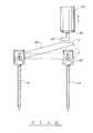
- FIG. 5is a view of one embodiment of a guide system configured to position multiple instruments associated with adjacent screws in a desired position
- FIG. 6a front view of the guide system of the FIG. 5 illustrating a combination of an awl and outer and inner dilators
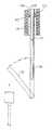
- FIG. 7is an isometric view of a tissue cutting instrument configured in accordance with the invention.
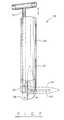
- FIG. 8is an elevated front view of a rod holder system configured in accordance with the invention and shown in a primary position of the connecting rod in which the latter is engaged inside the rod holder;
- FIG. 9is a sectional view of the rod holder system of FIG. 7 illustrating the initial stage of the rod's displacement towards its final position;
- FIG. 10is an isometric view of one embodiment of the rod holder system configured to establish the final position of the connecting rod, in which the trailing end thereof is received in the second screw;
- FIG. 11is an isometric view of another embodiment of the rod holder system.
- FIG. 12is a side view illustrating a rod guide system establishing the final position of the connecting rod
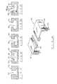
- FIG. 13is an isometric view of a placement system for establishing the desired trajectory of the guide system relative to the entry points into the pedicles to be interlinked;
- FIG. 14is a top view of a combination of the inner frame and the cradle frame of the placement system illustrated in FIG. 13 ;
- FIG. 15is a front view of the placement system illustrated in FIG. 13 ;
- FIG. 16is an embodiment of the outer frame of the positioning system shown in FIG. 13 ;
- FIGS. 17-21illustrate different embodiments of track structures provided in the outer frame of FIGS. 13 and 15 for engaging the inner frame of the placement system;
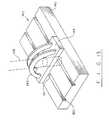
- FIG. 22is an isometric view of one embodiment of the cradle of the placement system illustrated in FIG. 13 ;
- FIG. 23is another embodiment of the cradle of the placement system of FIG. 13 .
- the inventive methodis performed to interlink vertebra to be fused by percutaneously guiding a connecting rod 66 in alignment with a longitudinal A-A axis of a screw 54 and, upon coupling the connecting rod 66 with this screw, pivoting the rod 66 so that it bridges adjacent screws 54 . Accordingly, a pathway formed for one of the adjacent screws 54 , which is advanced along this pathway towards the pedicle of one of the vertebra to be fused, is subsequently traversed by the connecting rod 66 that, thus, is automatically aligned with and engages a screw head 60 of the one screw 54 .
- Inventive system 55configured to assist the surgeon to perform the inventive method, in addition to the screws 54 and the connecting rod 66 , includes nuts 78 securing leading 70 ( FIG. 4 ) and trailing 72 ends of the connecting rod 66 after the pedicles have been positioned relative to one another.
- Vertical displacement of the rod 66requires that the screw head 60 be configured to receive the leading end 70 of the rod 66 from above in a first or primary position of the rod 66 , in which the latter and a shank 56 of the first screw 54 are aligned.
- the screw head 60is formed with a peripheral wall defining a central opening dimensioned to receive the leading end 70 of the rod 66 in the primary position thereof.
- the peripheral wall of the screw head 60is slotted and recessed. As shown in FIG. 4 , two recesses 64 , each formed in a respective segment of the peripheral wall, are aligned with one another and dimensioned to receive a pin 68 provided on the leading end 70 of the rod 66 .
- the recesses 64 and the pin 68are configured to provide rotational motion of the rod 66 about its leading end 70 while confining the latter within the screw head 60 between aligned slots 62 during the rotation of the rod 66 .
- the screw head 60receives the leading end 70 of the rod 66 from above and has at least one slot 62 and a pair of recesses 64 which are dimensioned to allow the rod 66 to rotate.
- the leading end 70 of the rod 66can be permanently attached to the screw head 60 .
- the pin 68is formed as an integral part of the screw head 60 , and the leading end 70 is permanently and pivotally mounted on the pin 68 .
- the trailing end 72 of the rod 66engages the screw head 60 of the adjacent screw 54 , which is inserted into the pedicle of the second one of the vertebra to be fused.
- the trailing end 72 of the rod 66is displaced along an arcuate path towards and placed through the slot 62 into the screw head 60 of the adjacent screw 54 .
- the slots 62 formed in screw heads 60 of the one and adjacent screws 54have to be located in a certain spatial relationship with respect to one another.
- the slots 62 of the screw head 60 of the screw 54 , receiving the trailing end 72 of the rod 66 , and the screw 54 coupled to the leading end 70can be aligned, if the rod 66 is straight.
- the slots 62 of the adjacent screws 54can be located in a desired angular position relative to one another, if the rod 66 is curved.
- One of the reasons why the rod 66 may be curvedis to connect the adjacent screws 54 introduced into the pedicles, which may extend at different angles, as is well known in the art.
- the curved rodis also useful in maintaining lordosis of the lumbar spine.
- each of the screws 54has a rotational component, such as a ratcheting or hinged mechanism, or a ball-in-socket joint 58 , as shown in FIGS. 3 and 4 .
- the ballpreferably formed on the top of the shank 56 .
- the screw head 60 of the screw 54conjoins to the ball of the ball-in-socket joint 58 by the socket of the latter, which surrounds the ball.
- the socketforms the undersurface or bottom of the screw head 60 .
- This mechanismwould allow the screw head 60 a substantial amount of rotational latitude, thus ultimately adjusting the path of the rod.
- the bottom of the head 60may be provided with the ball, whereas the top of the shank 56 carries the socket.
- FIGS. 5-6illustrate a guide system configured to provide displacement of the screws 54 to the pedicles of the vertebra to be fused and to establish the desired position between the screw placement instruments associated with the adjacent screws 54 .
- This systemincludes a pair of tubular sheaths 81 positioned in alignment with entry points of the screws 54 into the pedicles.
- the sheaths 81may function as guides for further installation of screw placement instruments including a plurality of inner 86 and outer 80 dilators forming the pathways for the screws 54 , which extend from the skin to the entry points of the screws into the pedicles to be interlinked.
- the adjacent screws 54are to be interlinked by the connecting rod 66 , which is displaced to its final position while the outer dilators 80 are still being locked in the pedicles for the reasons explained below. Accordingly, the rod 66 in the final position thereof should extend through the outer dilators 80 , which, for this and other reasons, as explained below, are formed with slits 82 . Therefore, the slits 82 are to be positioned so as to allow the rod 66 to penetrate through them before it interlinks the screws 54 in its final position. To provide such a desired position of the slits 82 , the tubular sheaths 81 have to be placed relative to one another in a predetermined spatial relationship.
- Changing the length of the retractable arm 84having either a telescopic structure or a mechanism translating rotational motion into a linear one, allows proper placement of the sheaths 81 in the pedicles to be interlinked.
- the screw placement instruments including inner 86 and outer dilators 80are sequentially introduced over each of the sheaths 81 and lodge in the respective pedicles.
- the outer dilator 80is provided with two to three small fixation pegs, so when it is positioned against the bone at the entry point to the pedicles, its position can be maintained through out the required portion of the surgery.
- the retractable arm 84allows the introduction of each subsequent dilator only in one position, in which the slits 82 of the progressively larger dilators straddle the opposite ends of the arm 84 .
- Diameters of sequentially inserted and progressively larger dilatorsdiffer from one another such that each subsequent dilator has its inner diameter approximating the outer diameter of the previous dilator to prevent the entry of tissue into the plane between the two dilators while allowing relative displacement of the dilators 80 , 86 .
- Another configuration of the guide systemincludes the sheaths 81 and the retractable arms 84 , which provides the initial desired position of the sheaths 81 relative to the pedicles.
- the retractable armis removably attached to the sheaths 81 and is detached once the desired position of the sheath has been established.
- the outer surfaces of the sheaths 81have guiding surfaces 91 . Mating with the guiding surfaces 91 are complementary shaped guiding surfaces 93 formed on the subsequently introduced inner and outer dilators 86 , 80 .
- the outer dilators 80 lodged in the adjacent pediclescan be located relative to one another only in one position characterized by the aligned spatial relationship between the slits 82 .
- the guiding surfaces 91 , 93can be formed along a part of the length of the sheaths and dilators and can be provided with various cross sections including rounded or polygonal projections and complementary shaped indents.
- the dilatorsmay be formed with displaceable panels 83 (see FIG. 8 ) uncovering the slit 82 after the dilators have been lodged in the pedicles.
- the sheaths 81 , dilators 80 , 86 , and awls 87are preferably made from radiolucent material such as hard plastic, carbon fiber, or any other substance, which is firm to provide the pathway.
- the tips of the instruments, having contact with the pedicles,must be traced to prevent damage to the pedicles and, as a consequence, are made from radio-opaque material depending on quality of which, the tips may be either reusable or disposable.
- the dilators 80 , 86have respective tips configured to be relatively sharp to be able to penetrate percutaneously and to cut the subcutaneous tissue on their way towards the pedicles.
- the tip of the awl 87which is designed to disrupt the pedicle for subsequent insertion of the screws 54 , is much sharper than the tips of the dilators and can be formed with pyramidal, conical or rounded shape. It is advantageous, but not necessary, to initially install the awl 87 before the dilators. However, such a sequence helps avoid the possibility of injury with the sharp tip of the dilators in the event that placement is initially incorrect.
- the awls 87guided either manually, or with the use of a standard operating room mallet, can be cannulated to allow for the passage of an orthopedic pin passable into pedicle to provide a guide for the screws 54 thus cannulated to be placed over the pin.
- the tip of the awl 87is made from radioopaque material to help the surgeon trace the awl's advancement during the surgery.
- the tipmay be configured to be disposable for a single event so as to preserve its sharpness, or alternatively, it may be reusable.
- the awls 87are removed from the outer dilators 80 to allow for the passage of further instruments that may, for example, be a drill, not shown in the drawings.
- the drillis configured such that the “wobble” thereof inside the outer dilator 80 is minimized.
- the pegs installed on the dilatorsare instrumental in reducing the wobble.
- One of the inventive configurations of the drillmay include a guiding surface dimensioned and shaped to mate with the guiding surfaces 91 ( FIG. 6 ) of the outer dilator 80 .
- the drill tipwidens the initial disruption of the pedicle made by the awl 87 , it still has a small diameter to prevent damage to the pedicle.
- the drillcan be cannulated to provide a passage for a guide wire remaining in the tract upon removal of the drill, and the drill's tip is made from radioopaque material to trace the drill's position relative to the pedicle.
- the screws 54are introduced in a sequential manner into the adjacent pedicles of the vertebra to be fused located on one side of the spine and, then, when the entire procedure is repeated, another pair of the screws 54 is introduced into the pedicles located on the opposite side of the spine.
- the unique structure of the screws 54 allowing the rod 66 to be introduced vertically into the screw head 60defines the ability of this system to achieve percutaneous placement of the screws and rods in accordance with the inventive method.
- the order of the placement of the screwis not important, it is desirable to introduce the screw 54 ( FIG. 3 ) having the head 60 formed with the recesses 64 pivotally engaging the leading end 70 of the rod 66 .
- the screws 54 penetrating the pedicle and vertebral bodyare preferably composed of titanium, although stainless steel, other metals, or any other material, including bioabsorbable materials could be utilized for performing the inventive method.
- Dimensions of the screws 54are not limited to the uniform size, both in terms of the diameter of the screw as well as the length of the screw.
- the inner diameter of the screwmay increase in size from the tip of the shank 56 of the screw 54 ( FIG. 3 ) to the screw head 60 to maintain bone purchase while minimizing the risk of screw breakage.
- the tip, thread, and pitch of the screware structured so as to allow the screws 54 to be passed into the pedicle and vertebral body without requiring complete drilling or tapping along the course and trajectory through the pedicle and vertebral body.
- a tissue-cutting instrument 26has a cylindrical body 28 configured to slide through the outer dilator 80 in a manner similar to the other instruments.
- a blade 34pivots between a rest position, in which the blade is withdrawn in the body 28 , and a cutting position, when the blade extends through the slits 82 of the adjacent outer dilators 80 .
- the bladehas to be fully withdrawn within the body 28 , which is thus recessed at 30 .
- Such an aligned positioncan be automatically set by providing the opposing surfaces of the body 28 and the outer dilator 80 with the guiding surfaces 91 ( FIG. 6 ) mating with one another to define the aligned position during displacement of the body 28 through the dilator 80 .
- a structure for pivoting the blade 34includes a mechanism translating linear motion of a blade-actuating rod 32 into pivoting motion of the blade 34 .
- the downward pivoting action of the blade 34is accomplished during an upward stroke of the actuating rod 32 .
- a distal end 36 of the actuating rod 32is recessed to form two identical arms bridged by a pin 38 , which serves as a fulcrum for the blade 34 a portion of which is rotatably mounted on the pin 38 between these arms.
- the distal end of the body 28is provided with another pin 42 bridging the bottom of the recess 30 and spaced from the pin 38 such that the blade 34 extends at a right angle to the body 28 in its cutting position.
- the blade 34has a short slot 40 providing a cam surface for the pin 42 which traverses the slot 40 .
- a combination of the linear force generated by the rod 32 and the torque created by the pin 42provides the blade 34 with pivotal motion terminating when the blade 34 extends horizontally into the slit 82 of the adjacent outer dilator 80 in the blade's cutting position.
- its opposite edgesare both cutting edges capable of providing a cut in opposite directions of the blade's displacement.
- the actuating rod 32is eccentrically placed with respect to the axis of symmetry of the body 28 to allow the blade to be fully accommodated within the body 28 in the rest position of the blade.
- the blade 34pivots to its cutting position during a downward stroke of the actuating rod 32 .
- the blade 34has the slot 40 , as shown in phantom lines in FIG. 7 , which is defined between two edges and extends unparallel to the longitudinal axis of the actuating rod 32 in the rest position of the blade.
- the distal end of the actuating rod 32is split into two arms attached to one another so that a pin connecting the arms extends through the slot. Accordingly, during a downstroke of the rod 32 , its distal end first slides along the slot without affecting its motion, but once the planes in which the rod 32 moves and the slot extends converge, the blade starts rotating about the pin 38 in its cutting position.
- tissue-cutting instrument 86can be installed in the adjacent outer dilator 80 , and the entire procedure can be repeated. While the tissue-cutting instrument 26 is shown to have a mechanical structure, any of thermal-, laser-, and ultrasound-cutting instruments can be utilized as well.
- the connecting rod 66is attached to the screw head 60 of one of the screws 54 by means of a rod holder system 100 , as illustrated in FIGS. 8 , 9 .
- the rod holder system 100includes a sleeve 104 slidingly guided through the outer dilator 80 to assume an aligned position, in which a recess 102 , formed on the sleeve 104 , coincides with the slit 82 provided on the outer dilator 80 . In this aligned position, and only in this position, the rod 66 can be displaced to its final position interlinking adjacent screws 54 .
- the opposing surfaces of the sleeve 104 and the outer dilator 80may be formed with the mating guiding surfaces 93 , as explained in reference to FIG. 6 .
- the rod holder 100is 1) to couple the leading end 70 with the screw head 60 , if the screw 54 is configured to have separate parts, and 2) to initiate displacement of the rod 66 in a desired direction so it will bridge the adjacent screw heads. Engagement between the rod 66 and the screw head 60 is realized by releasably locking the trailing end 72 of the rod 66 in the rod holder 100 .
- Numerous holding systemssuch as a chuck, a spring-loaded ball mechanism, or simply an O-ring made from frictional material and provided on the inner surface of the sleeve, can be incorporated within the sleeve 104 . In case of the spring-loaded ball mechanism, as shown in FIGS.
- balls 108 , 110 holding the trailing end 72 of the rod 66can retract laterally and let the rod 66 go in response to an external force created by the surgeon.
- the O-ringis configured to hold the rod 66 until the external force is applied.
- the rod holder 100would have a rotational actuator bringing engaging surfaces of the chuck towards and away from one another.
- the screw head 60( FIG. 3 ) is preliminary rotated in a position in which the pin 68 of the rod 66 automatically extends through and engages the recesses 64 formed in the screw head 60 .
- the inner surface of the outer dilatormay be provided with additional guide formations allowing the screw head 60 to slide through the outer dilator 80 only in one position, in which the slots 62 are automatically aligned with the dilator's slit 82 .
- Such a structurecan be advantageous for the screw configuration having the leading end 70 of the rod 66 permanently attached to the screw head 60 .
- a structure converting a thrust produced by a push rod 116 into the rotation of the rod 66includes the specifically configured trailing end 72 of the rod 66 and a distal end of the push rod 116 opposing one another within the rod holder 100 . Particularly, as shown in FIG. 9 , these ends are complementary slanted to allow the push rod 116 to apply the necessary torque in a desired direction towards the adjacent outer dilator.
- the push rod 116is actuated to apply the torque to the trailing end 72 of the rod 66 causing the latter to rotate about is leading end 70 towards the rod's final position.
- the inventionprovides for a rod-guiding tool 120 illustrated in FIGS. 1O-12 .
- the rod-guiding tool 120includes an arm 128 capable of engaging and guiding the trailing end 72 of the rod 66 into a respective screw head 60 of the screw 54 .
- a free end 130 of the armcan have a paddle-like shape (not shown) configured to press against the trailing end 72 of the connecting rod 66 and to bring it into the screw head 60 , as the housing 122 is being pulled upwards.
- the housing 122may have the guiding surface mating with the guiding surface of the outer dilator 80 to establish the alignment between the arm 128 and the slit 82 of the dilator 80 .
- Still another embodiment of the rod guiding tool 120may have the housing 120 provided with an arm carrier 124 which is formed as a unitary piece having an L-shaped distal end 130 functioning as the arm 128 . Displacing the arm carrier 124 downwards within the housing 122 provides actuation of the arm 128 .
- the above disclosed inventive method and systemare directed to interlink at least a pair of pedicles of the vertebra to be fused identified by placing appropriate landmarks on the skin such that they are aligned with the entry points to the pedicles.
- An identifying procedure of the inventive processuses an X-ray imaging, fluoroscopic, ultrasound and computer-guiding techniques for identifying the pedicles to be landmarked.
- this procedureinvolves preparing a sterile, transparent sheet of plastic which has on it an outline of the profile of the lumbar spine as seen, for example, from the anteroposterior projection, (hereinafter referred to the A-P) of an image of the spine. Also on this sheet is an oval, for identifying the pedicle from an approximately 30-degree A-P oblique view.
- the sterile sheet with the fiducial incorporated withinis placed on the skin of the patient's lumbar spine, and A-P views are obtained.
- the sheetcan be moved until the profile, as seen on the A-P view, is matched with the lateral aspect of the lumbar spine.
- Appropriate softwarecan be written so that in this way, the various image-guided systems could be utilized if available, but the recommendation would be to still utilize radiological imagery to some degree.
- the fiducial sheetis further displaced on the skin so that when the profile of the lumbar spine matches the outlines on the fiducial, an imaging component, such as a fluoroscopic camera, can be brought into an approximately 30-degree A-P oblique view. It has been proposed that this is the most accurate view for viewing the pedicle.
- This systemcan be refined further through several adjustments, including a simple system for measuring the angle of the pedicles on pre-op studies. This consists of a compass-like transparency to be placed against the preoperative transaxial images, measuring the angle of the pedicles as they enter the vertebral body. In general, it has been accepted that this angle is approximately 5-degrees at L3, 10-degrees at L4, 15-degrees at L5, and 20 degrees at S1.
- the inventive systemfurther includes a positioning system or assembly shown in FIGS. 13-23 assisting the surgeon in establishing the desired trajectory of tissue dissecting instruments. As is illustrated in FIG.
- a placement system 140enables a hollow guide 148 , subsequently traversed by one of the dilators or the sheath 81 , to be aligned with the landmark and positioned at a desired angle with respect to the pedicle. Accordingly, the instrument(s) passes through the interior of the hollow guide 148 towards the pedicles along the optimally established screw pathway.
- the placement system 140includes a rectangular outer frame 142 , provided with tracks 150 , which extend along the spine, an inner frame 144 , displaceable along the tracks, and a cradle 146 carrying the guide 148 operative to move transversely to the spine.
- the outer frame 142it has a transparent base, the bottom of which is temporarily attached to the transparent sheet with the landmarks either by adhesive, or by small piercing blades or pins that are inserted into the outer layer of the skin.
- the outer frame 142is mounted on two connector stand-holders 152 that connect to the sides of the operating table and operative to establish the desired height of the placement system 140 .
- the outer frame 142may be locked in a desired position by activating a locking mechanism 154 .
- the outer framemay have a two-half base 156 , each provided with a respective track 150 . Provision of the two-part base of the outer frame 142 eliminates the necessity of forming a central recess accommodating the guide 148 within the base 156 .
- the inner frame 144 of the placement system 140allows the adjustment of the hollow guide 148 along the spine as it slides along the tracks 150 of the outer frame 142 .
- the bottom of the inner frame 144has guide surfaces 151 ( FIGS. 3 , 13 , 22 ) extending complementary to the tracks 150 of the outer frame 142 and configured to allow sliding motion of these frames relative to one another.
- Various cross-sections of the tracks 150 having one of T-, U-, V-, C- and L-shapes necessitating complementary surfaces on the inner frame 144can be implemented.
- the track 150is provided with an inverted T-shape having a trapezoidal bottom.
- FIG. 18shows a T-shaped recess provided with two undercuts 152 , which are formed in upper sides 165 of the track 150 .
- the track 150as shown in FIG. 19 , has an inverted T shape, whereas the bottom of the track 150 of FIG. 20 is provided with a C-shape.
- FIG. 21illustrates the track 150 with two lateral surfaces 160 extending inwards from opposite walls of the track 150 and terminating at a distance from one another to form a two-level rectangular compartments 162 .
- FIGS. 15 , 22 and 23two modifications of the cradle 146 mounted on the inner frame 144 and providing controllable displacement of the hollow guide 148 in a direction transverse to the longitudinal dimension of the spine is shown in FIGS. 15 , 22 and 23 .
- the inner frame 144may receive a base of the cradle 146 which, in combination with the outer frame 142 , not shown on this figure, provide displacement of the of the guide 148 in a medial-lateral plane and a cranial-caudal plane.
- the inner frame 144is provided with a guide rail 166 that can have a polygonal or circular cross-section and has a slide 168 operative to move along the guide rail 166 .
- the slide 168is provided with an arcuate element 170 rigidly attached to the hollow guide 148 , which, in turn, is pivotally mounted on the inner frame 144 .
- a desired angle of the hollow guide 148derived from preoperative studies by evaluating the angle the pedicle unites with the vertebral body, can be established when a mark 182 on the slide 168 coincides with the desired calibration mark on a scale 172 .
- the other configuration of the cradle 146has a pair of arcuate elements 174 provided with recesses 188 , which define a path for the guide 148 mounted on a crossbar 186 slidable along the recesses 188 , which are aligned with one another.
- the crossbarhas at least one locking nut 176 provided with a mark 184 that, when brought in alignment with a respective mark on the scale 180 corresponding to the selected angle, indicates the desired angular position of the guide 148 , which is then locked in this position by tightening the nut 176 against the guide 174 .
- the hollow guide 148establishes the trajectory of the entry into the pedicle and, in particular, into the oval fiducial demarcating the entry point into the pedicle.
- the established trajectoryallows the screws 54 to pass through the pedicles in the safest way, minimizing risk to important peri-pedicular structures, particularly the nerve roots and thecal sac.
- the placement system 140also insures that the screws 54 lie entirely within the pedicle, thus reducing the opportunity for screw breakage or pullout.
Landscapes
- Health & Medical Sciences (AREA)
- Orthopedic Medicine & Surgery (AREA)
- Surgery (AREA)
- Life Sciences & Earth Sciences (AREA)
- Neurology (AREA)
- Animal Behavior & Ethology (AREA)
- Public Health (AREA)
- Heart & Thoracic Surgery (AREA)
- Medical Informatics (AREA)
- Molecular Biology (AREA)
- Engineering & Computer Science (AREA)
- General Health & Medical Sciences (AREA)
- Biomedical Technology (AREA)
- Veterinary Medicine (AREA)
- Nuclear Medicine, Radiotherapy & Molecular Imaging (AREA)
- Oral & Maxillofacial Surgery (AREA)
- Dentistry (AREA)
- Surgical Instruments (AREA)
- Orthopedics, Nursing, And Contraception (AREA)
- Joining Of Building Structures In Genera (AREA)
Abstract
Description
Claims (28)
Priority Applications (1)
| Application Number | Priority Date | Filing Date | Title |
|---|---|---|---|
| US11/463,539US8382802B2 (en) | 2002-08-21 | 2006-08-09 | Systems, methods and devices for placement of bone anchors and connectors |
Applications Claiming Priority (3)
| Application Number | Priority Date | Filing Date | Title |
|---|---|---|---|
| US40526102P | 2002-08-21 | 2002-08-21 | |
| US10/320,989US7306603B2 (en) | 2002-08-21 | 2002-12-17 | Device and method for percutaneous placement of lumbar pedicle screws and connecting rods |
| US11/463,539US8382802B2 (en) | 2002-08-21 | 2006-08-09 | Systems, methods and devices for placement of bone anchors and connectors |
Related Parent Applications (1)
| Application Number | Title | Priority Date | Filing Date |
|---|---|---|---|
| US10/320,989ContinuationUS7306603B2 (en) | 2002-08-21 | 2002-12-17 | Device and method for percutaneous placement of lumbar pedicle screws and connecting rods |
Publications (2)
| Publication Number | Publication Date |
|---|---|
| US20070016198A1 US20070016198A1 (en) | 2007-01-18 |
| US8382802B2true US8382802B2 (en) | 2013-02-26 |
Family
ID=31891032
Family Applications (4)
| Application Number | Title | Priority Date | Filing Date |
|---|---|---|---|
| US10/320,989Expired - LifetimeUS7306603B2 (en) | 2002-08-21 | 2002-12-17 | Device and method for percutaneous placement of lumbar pedicle screws and connecting rods |
| US11/463,546Expired - Fee RelatedUS8202304B2 (en) | 2002-08-21 | 2006-08-09 | Methods and systems for performing spinal surgery |
| US11/463,543Active2026-11-11US8579942B2 (en) | 2002-08-21 | 2006-08-09 | Systems, methods and tools for spinal surgery |
| US11/463,539Expired - Fee RelatedUS8382802B2 (en) | 2002-08-21 | 2006-08-09 | Systems, methods and devices for placement of bone anchors and connectors |
Family Applications Before (3)
| Application Number | Title | Priority Date | Filing Date |
|---|---|---|---|
| US10/320,989Expired - LifetimeUS7306603B2 (en) | 2002-08-21 | 2002-12-17 | Device and method for percutaneous placement of lumbar pedicle screws and connecting rods |
| US11/463,546Expired - Fee RelatedUS8202304B2 (en) | 2002-08-21 | 2006-08-09 | Methods and systems for performing spinal surgery |
| US11/463,543Active2026-11-11US8579942B2 (en) | 2002-08-21 | 2006-08-09 | Systems, methods and tools for spinal surgery |
Country Status (8)
| Country | Link |
|---|---|
| US (4) | US7306603B2 (en) |
| EP (2) | EP1545355B1 (en) |
| AT (1) | ATE416703T1 (en) |
| AU (1) | AU2003260019B2 (en) |
| CA (1) | CA2496371C (en) |
| DE (1) | DE60325242D1 (en) |
| MX (1) | MXPA05002050A (en) |
| WO (1) | WO2004017847A2 (en) |
Cited By (3)
| Publication number | Priority date | Publication date | Assignee | Title |
|---|---|---|---|---|
| US9011450B2 (en) | 2012-08-08 | 2015-04-21 | DePuy Synthes Products, LLC | Surgical instrument |
| US10758285B2 (en) | 2016-08-24 | 2020-09-01 | Integrity Implants Inc. | Length adjustable modular screw system |
| US10779866B2 (en) | 2016-12-29 | 2020-09-22 | K2M, Inc. | Rod reducer assembly |
Families Citing this family (319)
| Publication number | Priority date | Publication date | Assignee | Title |
|---|---|---|---|---|
| US20050267481A1 (en) | 2003-10-17 | 2005-12-01 | Allen Carl | Systems, devices and apparatuses for bony fixation and disk repair and replacement and methods related thereto |
| WO2007084649A2 (en)* | 2006-01-17 | 2007-07-26 | Highgate Orthopedics, Inc. | Systems, devices and apparatuses for bony fixation and disk repair and replacement and methods related thereto |
| US7833250B2 (en) | 2004-11-10 | 2010-11-16 | Jackson Roger P | Polyaxial bone screw with helically wound capture connection |
| US10258382B2 (en) | 2007-01-18 | 2019-04-16 | Roger P. Jackson | Rod-cord dynamic connection assemblies with slidable bone anchor attachment members along the cord |
| US8353932B2 (en) | 2005-09-30 | 2013-01-15 | Jackson Roger P | Polyaxial bone anchor assembly with one-piece closure, pressure insert and plastic elongate member |
| US8292926B2 (en) | 2005-09-30 | 2012-10-23 | Jackson Roger P | Dynamic stabilization connecting member with elastic core and outer sleeve |
| US20160242816A9 (en)* | 2001-05-09 | 2016-08-25 | Roger P. Jackson | Dynamic spinal stabilization assembly with elastic bumpers and locking limited travel closure mechanisms |
| US7862587B2 (en) | 2004-02-27 | 2011-01-04 | Jackson Roger P | Dynamic stabilization assemblies, tool set and method |
| US10729469B2 (en) | 2006-01-09 | 2020-08-04 | Roger P. Jackson | Flexible spinal stabilization assembly with spacer having off-axis core member |
| US7306603B2 (en) | 2002-08-21 | 2007-12-11 | Innovative Spinal Technologies | Device and method for percutaneous placement of lumbar pedicle screws and connecting rods |
| US8876868B2 (en) | 2002-09-06 | 2014-11-04 | Roger P. Jackson | Helical guide and advancement flange with radially loaded lip |
| WO2006052796A2 (en) | 2004-11-10 | 2006-05-18 | Jackson Roger P | Helical guide and advancement flange with break-off extensions |
| US9539012B2 (en) | 2002-10-30 | 2017-01-10 | Zimmer Spine, Inc. | Spinal stabilization systems with quick-connect sleeve assemblies for use in surgical procedures |
| AU2003287273C1 (en) | 2002-10-30 | 2010-01-07 | Zimmer Spine, Inc. | Spinal stabilization system insertion and methods |
| US20040158254A1 (en)* | 2003-02-12 | 2004-08-12 | Sdgi Holdings, Inc. | Instrument and method for milling a path into bone |
| JP2004301157A (en)* | 2003-03-28 | 2004-10-28 | Nichias Corp | Squeal prevention shim structure and disc brake device having the same |
| TWI315010B (en)* | 2003-03-31 | 2009-09-21 | Sharp Corporatio | Liquid crystal display device and method of manufacturing the same |
| US6716214B1 (en) | 2003-06-18 | 2004-04-06 | Roger P. Jackson | Polyaxial bone screw with spline capture connection |
| US7621918B2 (en) | 2004-11-23 | 2009-11-24 | Jackson Roger P | Spinal fixation tool set and method |
| US7377923B2 (en) | 2003-05-22 | 2008-05-27 | Alphatec Spine, Inc. | Variable angle spinal screw assembly |
| US8377102B2 (en) | 2003-06-18 | 2013-02-19 | Roger P. Jackson | Polyaxial bone anchor with spline capture connection and lower pressure insert |
| US20100211114A1 (en)* | 2003-06-18 | 2010-08-19 | Jackson Roger P | Polyaxial bone anchor with shelf capture connection |
| US8926670B2 (en) | 2003-06-18 | 2015-01-06 | Roger P. Jackson | Polyaxial bone screw assembly |
| US7776067B2 (en) | 2005-05-27 | 2010-08-17 | Jackson Roger P | Polyaxial bone screw with shank articulation pressure insert and method |
| US8398682B2 (en) | 2003-06-18 | 2013-03-19 | Roger P. Jackson | Polyaxial bone screw assembly |
| US8137386B2 (en) | 2003-08-28 | 2012-03-20 | Jackson Roger P | Polyaxial bone screw apparatus |
| US7967850B2 (en) | 2003-06-18 | 2011-06-28 | Jackson Roger P | Polyaxial bone anchor with helical capture connection, insert and dual locking assembly |
| US7766915B2 (en) | 2004-02-27 | 2010-08-03 | Jackson Roger P | Dynamic fixation assemblies with inner core and outer coil-like member |
| US8366753B2 (en) | 2003-06-18 | 2013-02-05 | Jackson Roger P | Polyaxial bone screw assembly with fixed retaining structure |
| US8257398B2 (en) | 2003-06-18 | 2012-09-04 | Jackson Roger P | Polyaxial bone screw with cam capture |
| US6945974B2 (en) | 2003-07-07 | 2005-09-20 | Aesculap Inc. | Spinal stabilization implant and method of application |
| US6945975B2 (en)* | 2003-07-07 | 2005-09-20 | Aesculap, Inc. | Bone fixation assembly and method of securement |
| US7955355B2 (en) | 2003-09-24 | 2011-06-07 | Stryker Spine | Methods and devices for improving percutaneous access in minimally invasive surgeries |
| US8002798B2 (en) | 2003-09-24 | 2011-08-23 | Stryker Spine | System and method for spinal implant placement |
| WO2007079242A2 (en)* | 2005-12-29 | 2007-07-12 | Highgate Orthopedics, Inc. | Devices and methods for bony fixation and disk repair and replaceme |
| US7967826B2 (en)* | 2003-10-21 | 2011-06-28 | Theken Spine, Llc | Connector transfer tool for internal structure stabilization systems |
| US7588588B2 (en)* | 2003-10-21 | 2009-09-15 | Innovative Spinal Technologies | System and method for stabilizing of internal structures |
| US7588575B2 (en)* | 2003-10-21 | 2009-09-15 | Innovative Spinal Technologies | Extension for use with stabilization systems for internal structures |
| WO2005039392A2 (en)* | 2003-10-22 | 2005-05-06 | Endius Incorporated | Method and surgical tool for inserting a longitudinal member |
| US9055934B2 (en)* | 2004-08-26 | 2015-06-16 | Zimmer Spine, Inc. | Methods and apparatus for access to and/or treatment of the spine |
| US11419642B2 (en)* | 2003-12-16 | 2022-08-23 | Medos International Sarl | Percutaneous access devices and bone anchor assemblies |
| US7666188B2 (en)* | 2003-12-16 | 2010-02-23 | Depuy Spine, Inc. | Methods and devices for spinal fixation element placement |
| KR20070029650A (en)* | 2003-12-16 | 2007-03-14 | 디퍼이 스파인 인코포레이티드 | Methods and instruments for minimally invasive spinal cord fixation element placement |
| US7648506B2 (en) | 2003-12-16 | 2010-01-19 | Depuy Acromed, Inc. | Pivoting implant holder |
| US7179261B2 (en)* | 2003-12-16 | 2007-02-20 | Depuy Spine, Inc. | Percutaneous access devices and bone anchor assemblies |
| US7527638B2 (en)* | 2003-12-16 | 2009-05-05 | Depuy Spine, Inc. | Methods and devices for minimally invasive spinal fixation element placement |
| US7311712B2 (en)* | 2004-02-26 | 2007-12-25 | Aesculap Implant Systems, Inc. | Polyaxial locking screw plate assembly |
| US8152810B2 (en) | 2004-11-23 | 2012-04-10 | Jackson Roger P | Spinal fixation tool set and method |
| US7160300B2 (en) | 2004-02-27 | 2007-01-09 | Jackson Roger P | Orthopedic implant rod reduction tool set and method |
| US11241261B2 (en) | 2005-09-30 | 2022-02-08 | Roger P Jackson | Apparatus and method for soft spinal stabilization using a tensionable cord and releasable end structure |
| JP2007525274A (en) | 2004-02-27 | 2007-09-06 | ロジャー・ピー・ジャクソン | Orthopedic implant rod reduction instrument set and method |
| US7547318B2 (en) | 2004-03-19 | 2009-06-16 | Depuy Spine, Inc. | Spinal fixation element and methods |
| US7214227B2 (en)* | 2004-03-22 | 2007-05-08 | Innovative Spinal Technologies | Closure member for a medical implant device |
| US7909852B2 (en) | 2004-03-31 | 2011-03-22 | Depuy Spine Sarl | Adjustable-angle spinal fixation element |
| US8475495B2 (en) | 2004-04-08 | 2013-07-02 | Globus Medical | Polyaxial screw |
| US7503924B2 (en) | 2004-04-08 | 2009-03-17 | Globus Medical, Inc. | Polyaxial screw |
| US20050228380A1 (en)* | 2004-04-09 | 2005-10-13 | Depuy Spine Inc. | Instruments and methods for minimally invasive spine surgery |
| US8460310B2 (en) | 2004-08-04 | 2013-06-11 | Leslie Stern | Surgical base unit and retractor support mechanism |
| US7637914B2 (en)* | 2004-08-04 | 2009-12-29 | Leslie Stern | Surgical base unit and retractor support mechanism |
| US7465306B2 (en)* | 2004-08-13 | 2008-12-16 | Warsaw Orthopedic, Inc. | System and method for positioning a connecting member adjacent the spinal column in minimally invasive procedures |
| US7651502B2 (en) | 2004-09-24 | 2010-01-26 | Jackson Roger P | Spinal fixation tool set and method for rod reduction and fastener insertion |
| US7666189B2 (en)* | 2004-09-29 | 2010-02-23 | Synthes Usa, Llc | Less invasive surgical system and methods |
| US7575600B2 (en) | 2004-09-29 | 2009-08-18 | Kyphon Sarl | Artificial vertebral disk replacement implant with translating articulation contact surface and method |
| US7794477B2 (en) | 2004-10-05 | 2010-09-14 | Warsaw Orthopedic, Inc. | Spinal implants and methods with extended multi-axial anchor assemblies |
| US7722654B2 (en)* | 2004-10-05 | 2010-05-25 | Warsaw Orthopedic, Inc. | Spinal implants with multi-axial anchor assembly and methods |
| US7572280B2 (en)* | 2004-10-05 | 2009-08-11 | Warsaw Orthopedic, Inc. | Multi-axial anchor assemblies for spinal implants and methods |
| US8267969B2 (en) | 2004-10-20 | 2012-09-18 | Exactech, Inc. | Screw systems and methods for use in stabilization of bone structures |
| US8162985B2 (en) | 2004-10-20 | 2012-04-24 | The Board Of Trustees Of The Leland Stanford Junior University | Systems and methods for posterior dynamic stabilization of the spine |
| US7935134B2 (en) | 2004-10-20 | 2011-05-03 | Exactech, Inc. | Systems and methods for stabilization of bone structures |
| US20070239159A1 (en)* | 2005-07-22 | 2007-10-11 | Vertiflex, Inc. | Systems and methods for stabilization of bone structures |
| US8226690B2 (en)* | 2005-07-22 | 2012-07-24 | The Board Of Trustees Of The Leland Stanford Junior University | Systems and methods for stabilization of bone structures |
| US8025680B2 (en) | 2004-10-20 | 2011-09-27 | Exactech, Inc. | Systems and methods for posterior dynamic stabilization of the spine |
| WO2006047711A2 (en) | 2004-10-25 | 2006-05-04 | Alphaspine, Inc. | Pedicle screw systems and methods |
| US7604655B2 (en)* | 2004-10-25 | 2009-10-20 | X-Spine Systems, Inc. | Bone fixation system and method for using the same |
| US8075591B2 (en) | 2004-11-09 | 2011-12-13 | Depuy Spine, Inc. | Minimally invasive spinal fixation guide systems and methods |
| US8926672B2 (en) | 2004-11-10 | 2015-01-06 | Roger P. Jackson | Splay control closure for open bone anchor |
| US20110190822A1 (en)* | 2004-11-16 | 2011-08-04 | James Spitler | Internal Structure Stabilization System for Spanning Three or More Structures |
| US7569061B2 (en) | 2004-11-16 | 2009-08-04 | Innovative Spinal Technologies, Inc. | Off-axis anchor guidance system |
| US9980753B2 (en) | 2009-06-15 | 2018-05-29 | Roger P Jackson | pivotal anchor with snap-in-place insert having rotation blocking extensions |
| WO2006057837A1 (en) | 2004-11-23 | 2006-06-01 | Jackson Roger P | Spinal fixation tool attachment structure |
| US8444681B2 (en) | 2009-06-15 | 2013-05-21 | Roger P. Jackson | Polyaxial bone anchor with pop-on shank, friction fit retainer and winged insert |
| US9168069B2 (en) | 2009-06-15 | 2015-10-27 | Roger P. Jackson | Polyaxial bone anchor with pop-on shank and winged insert with lower skirt for engaging a friction fit retainer |
| US7875065B2 (en)* | 2004-11-23 | 2011-01-25 | Jackson Roger P | Polyaxial bone screw with multi-part shank retainer and pressure insert |
| US9216041B2 (en) | 2009-06-15 | 2015-12-22 | Roger P. Jackson | Spinal connecting members with tensioned cords and rigid sleeves for engaging compression inserts |
| US8308782B2 (en) | 2004-11-23 | 2012-11-13 | Jackson Roger P | Bone anchors with longitudinal connecting member engaging inserts and closures for fixation and optional angulation |
| WO2006058221A2 (en) | 2004-11-24 | 2006-06-01 | Abdou Samy M | Devices and methods for inter-vertebral orthopedic device placement |
| EP1719468A1 (en)* | 2004-12-17 | 2006-11-08 | Zimmer GmbH | Intervertebral stabilization system |
| US7785353B2 (en)* | 2005-02-02 | 2010-08-31 | Syberspine Limited | Integral, articulated, pedicle screw and longitudinal member for spinal osteosynthesis |
| US10076361B2 (en) | 2005-02-22 | 2018-09-18 | Roger P. Jackson | Polyaxial bone screw with spherical capture, compression and alignment and retention structures |
| US7901437B2 (en) | 2007-01-26 | 2011-03-08 | Jackson Roger P | Dynamic stabilization member with molded connection |
| WO2008024937A2 (en) | 2006-08-23 | 2008-02-28 | Pioneer Surgical Technology, Inc. | Minimally invasive surgical system |
| EP1858422A4 (en)* | 2005-02-23 | 2011-12-28 | Pioneer Surgical Technology Inc | Minimally invasive surgical system |
| CA2614898C (en)* | 2005-04-27 | 2014-04-22 | Trinity Orthopedics, Llc | Mono-planar pedilcle screw method, system, and kit |
| US7758617B2 (en)* | 2005-04-27 | 2010-07-20 | Globus Medical, Inc. | Percutaneous vertebral stabilization system |
| US9314273B2 (en) | 2005-04-27 | 2016-04-19 | Globus Medical, Inc. | Percutaneous vertebral stabilization system |
| US7491208B2 (en) | 2005-04-28 | 2009-02-17 | Warsaw Orthopedic, Inc. | Instrument and method for guiding surgical implants and instruments during surgery |
| US8177817B2 (en) | 2005-05-18 | 2012-05-15 | Stryker Spine | System and method for orthopedic implant configuration |
| US8523865B2 (en) | 2005-07-22 | 2013-09-03 | Exactech, Inc. | Tissue splitter |
| US7717943B2 (en) | 2005-07-29 | 2010-05-18 | X-Spine Systems, Inc. | Capless multiaxial screw and spinal fixation assembly and method |
| US7909830B2 (en)* | 2005-08-25 | 2011-03-22 | Synthes Usa, Llc | Methods of spinal fixation and instrumentation |
| US7695475B2 (en)* | 2005-08-26 | 2010-04-13 | Warsaw Orthopedic, Inc. | Instruments for minimally invasive stabilization of bony structures |
| US20070073290A1 (en)* | 2005-09-13 | 2007-03-29 | Boehm Frank H Jr | Insertion of artificial/prosthetic facet joints with ballotable/compressible joint space component |
| EP1926443B1 (en)* | 2005-09-23 | 2013-04-03 | Synthes GmbH | Bone support apparatus |
| US8105368B2 (en) | 2005-09-30 | 2012-01-31 | Jackson Roger P | Dynamic stabilization connecting member with slitted core and outer sleeve |
| US20080140076A1 (en)* | 2005-09-30 | 2008-06-12 | Jackson Roger P | Dynamic stabilization connecting member with slitted segment and surrounding external elastomer |
| WO2007041702A2 (en)* | 2005-10-04 | 2007-04-12 | Alphaspine, Inc. | Pedicle screw system with provisional locking aspects |
| US8002806B2 (en) | 2005-10-20 | 2011-08-23 | Warsaw Orthopedic, Inc. | Bottom loading multi-axial screw assembly |
| US8097025B2 (en) | 2005-10-25 | 2012-01-17 | X-Spine Systems, Inc. | Pedicle screw system configured to receive a straight or curved rod |
| WO2007061960A2 (en)* | 2005-11-18 | 2007-05-31 | Life Spine, Inc. | Dynamic spinal stabilization devices and systems |
| US8100946B2 (en) | 2005-11-21 | 2012-01-24 | Synthes Usa, Llc | Polyaxial bone anchors with increased angulation |
| US8034078B2 (en) | 2008-05-30 | 2011-10-11 | Globus Medical, Inc. | System and method for replacement of spinal motion segment |
| US7704271B2 (en) | 2005-12-19 | 2010-04-27 | Abdou M Samy | Devices and methods for inter-vertebral orthopedic device placement |
| US20080294198A1 (en)* | 2006-01-09 | 2008-11-27 | Jackson Roger P | Dynamic spinal stabilization assembly with torsion and shear control |
| US7927360B2 (en)* | 2006-01-26 | 2011-04-19 | Warsaw Orthopedic, Inc. | Spinal anchor assemblies having extended receivers |
| US7497869B2 (en)* | 2006-01-27 | 2009-03-03 | Warsaw Orthopedic, Inc. | Methods and devices for a minimally invasive placement of a rod within a patient |
| US7833252B2 (en) | 2006-01-27 | 2010-11-16 | Warsaw Orthopedic, Inc. | Pivoting joints for spinal implants including designed resistance to motion and methods of use |
| US7722652B2 (en) | 2006-01-27 | 2010-05-25 | Warsaw Orthopedic, Inc. | Pivoting joints for spinal implants including designed resistance to motion and methods of use |
| US8057519B2 (en)* | 2006-01-27 | 2011-11-15 | Warsaw Orthopedic, Inc. | Multi-axial screw assembly |
| USD589147S1 (en)* | 2006-02-02 | 2009-03-24 | Innovative Spinal Technologies | Bone anchor head |
| EP1981422B1 (en) | 2006-02-06 | 2018-10-24 | Stryker European Holdings I, LLC | Rod contouring apparatus for percutaneous pedicle screw extension |
| US8029545B2 (en)* | 2006-02-07 | 2011-10-04 | Warsaw Orthopedic Inc. | Articulating connecting member and anchor systems for spinal stabilization |
| US7520879B2 (en)* | 2006-02-07 | 2009-04-21 | Warsaw Orthopedic, Inc. | Surgical instruments and techniques for percutaneous placement of spinal stabilization elements |
| WO2007121271A2 (en)* | 2006-04-11 | 2007-10-25 | Synthes (U.S.A) | Minimally invasive fixation system |
| US7588593B2 (en)* | 2006-04-18 | 2009-09-15 | International Spinal Innovations, Llc | Pedicle screw with vertical adjustment |
| US8435267B2 (en)* | 2006-04-24 | 2013-05-07 | Spinefrontier Inc | Spine fixation method and apparatus |
| US8221468B2 (en) | 2006-05-11 | 2012-07-17 | Gaines Jr Robert W | Use of bioabsorbable materials for anterior extradiscal correction of thoracolumbar pathologies |
| EP1862135B1 (en)* | 2006-05-29 | 2017-07-05 | Stryker European Holdings I, LLC | Clamping element and insert therefor |
| US20080058808A1 (en)* | 2006-06-14 | 2008-03-06 | Spartek Medical, Inc. | Implant system and method to treat degenerative disorders of the spine |
| CN101496170B (en)* | 2006-07-31 | 2011-06-29 | 3M创新有限公司 | Integrated light source module |
| US20080051135A1 (en)* | 2006-07-31 | 2008-02-28 | 3M Innovative Properties Company | Combination camera/projector system |
| US20080036972A1 (en)* | 2006-07-31 | 2008-02-14 | 3M Innovative Properties Company | Led mosaic |
| JP2009545894A (en)* | 2006-07-31 | 2009-12-24 | スリーエム イノベイティブ プロパティズ カンパニー | LED source with hollow condenser lens |
| US8075140B2 (en)* | 2006-07-31 | 2011-12-13 | 3M Innovative Properties Company | LED illumination system with polarization recycling |
| EP2049947A1 (en) | 2006-07-31 | 2009-04-22 | 3M Innovative Properties Company | Optical projection subsystem |
| US7686809B2 (en) | 2006-09-25 | 2010-03-30 | Stryker Spine | Rod inserter and rod with reduced diameter end |
| US8162952B2 (en) | 2006-09-26 | 2012-04-24 | Ebi, Llc | Percutaneous instrument assembly |
| US7918857B2 (en) | 2006-09-26 | 2011-04-05 | Depuy Spine, Inc. | Minimally invasive bone anchor extensions |
| US8038699B2 (en) | 2006-09-26 | 2011-10-18 | Ebi, Llc | Percutaneous instrument assembly |
| US8096996B2 (en) | 2007-03-20 | 2012-01-17 | Exactech, Inc. | Rod reducer |
| US8052720B2 (en)* | 2006-11-09 | 2011-11-08 | Zimmer Spine, Inc. | Minimally invasive pedicle screw access system and associated method |
| US8211110B1 (en) | 2006-11-10 | 2012-07-03 | Lanx, Inc. | Minimally invasive tool to facilitate implanting a pedicle screw and housing |
| US8262662B2 (en)* | 2006-11-20 | 2012-09-11 | Depuy Spine, Inc. | Break-off screw extensions |
| US7931673B2 (en)* | 2006-12-06 | 2011-04-26 | Zimmer Spine, Inc. | Minimally invasive vertebral anchor access system and associated method |
| CA2670988C (en) | 2006-12-08 | 2014-03-25 | Roger P. Jackson | Tool system for dynamic spinal implants |
| US8734452B2 (en)* | 2006-12-15 | 2014-05-27 | Spinefrontier, Inc | Guidance system,tools and devices for spinal fixation |
| US8475498B2 (en) | 2007-01-18 | 2013-07-02 | Roger P. Jackson | Dynamic stabilization connecting member with cord connection |
| US8366745B2 (en) | 2007-05-01 | 2013-02-05 | Jackson Roger P | Dynamic stabilization assembly having pre-compressed spacers with differential displacements |
| US8435268B2 (en)* | 2007-01-19 | 2013-05-07 | Reduction Technologies, Inc. | Systems, devices and methods for the correction of spinal deformities |
| US20080177326A1 (en)* | 2007-01-19 | 2008-07-24 | Matthew Thompson | Orthosis to correct spinal deformities |
| US10792074B2 (en) | 2007-01-22 | 2020-10-06 | Roger P. Jackson | Pivotal bone anchor assemly with twist-in-place friction fit insert |
| US20080195153A1 (en)* | 2007-02-08 | 2008-08-14 | Matthew Thompson | Dynamic spinal deformity correction |
| US7648521B2 (en)* | 2007-03-15 | 2010-01-19 | Zimmer Spine, Inc. | System and method for minimally invasive spinal surgery |
| WO2008121343A1 (en)* | 2007-03-30 | 2008-10-09 | Vertiflex, Inc. | Multi-level minimally invasive spinal stabilization system |
| US20080256646A1 (en)* | 2007-04-12 | 2008-10-16 | Microsoft Corporation | Managing Digital Rights in a Member-Based Domain Architecture |
| US8202302B2 (en)* | 2007-04-19 | 2012-06-19 | Mi4Spine, Llc | Pedicle screw and rod system |
| WO2008134703A2 (en) | 2007-04-30 | 2008-11-06 | Globus Medical, Inc. | Flexible spine stabilization system |
| US10383660B2 (en) | 2007-05-01 | 2019-08-20 | Roger P. Jackson | Soft stabilization assemblies with pretensioned cords |
| US8979904B2 (en) | 2007-05-01 | 2015-03-17 | Roger P Jackson | Connecting member with tensioned cord, low profile rigid sleeve and spacer with torsion control |
| US8092501B2 (en) | 2007-06-05 | 2012-01-10 | Spartek Medical, Inc. | Dynamic spinal rod and method for dynamic stabilization of the spine |
| US8021396B2 (en) | 2007-06-05 | 2011-09-20 | Spartek Medical, Inc. | Configurable dynamic spinal rod and method for dynamic stabilization of the spine |
| US8048115B2 (en) | 2007-06-05 | 2011-11-01 | Spartek Medical, Inc. | Surgical tool and method for implantation of a dynamic bone anchor |
| US8048123B2 (en) | 2007-06-05 | 2011-11-01 | Spartek Medical, Inc. | Spine implant with a deflection rod system and connecting linkages and method |
| US8048128B2 (en) | 2007-06-05 | 2011-11-01 | Spartek Medical, Inc. | Revision system and method for a dynamic stabilization and motion preservation spinal implantation system and method |
| US8109970B2 (en) | 2007-06-05 | 2012-02-07 | Spartek Medical, Inc. | Deflection rod system with a deflection contouring shield for a spine implant and method |
| US8083772B2 (en) | 2007-06-05 | 2011-12-27 | Spartek Medical, Inc. | Dynamic spinal rod assembly and method for dynamic stabilization of the spine |
| US8052722B2 (en) | 2007-06-05 | 2011-11-08 | Spartek Medical, Inc. | Dual deflection rod system for a dynamic stabilization and motion preservation spinal implantation system and method |
| US8114134B2 (en) | 2007-06-05 | 2012-02-14 | Spartek Medical, Inc. | Spinal prosthesis having a three bar linkage for motion preservation and dynamic stabilization of the spine |
| US20080312704A1 (en)* | 2007-06-12 | 2008-12-18 | Zimmer Spine, Inc. | Instrumentation and associated techniques for minimally invasive spinal construct installation |
| US8460300B2 (en)* | 2007-06-12 | 2013-06-11 | Zimmer Spine, Inc. | Instrumentation and associated techniques for minimally invasive vertebral rod installation |
| US8313515B2 (en) | 2007-06-15 | 2012-11-20 | Rachiotek, Llc | Multi-level spinal stabilization system |
| US7947046B2 (en)* | 2007-06-21 | 2011-05-24 | Warsaw Orthopedic, Inc. | Anchor extenders for minimally invasive surgical procedures |
| US8043343B2 (en)* | 2007-06-28 | 2011-10-25 | Zimmer Spine, Inc. | Stabilization system and method |
| US8361126B2 (en) | 2007-07-03 | 2013-01-29 | Pioneer Surgical Technology, Inc. | Bone plate system |
| US8623019B2 (en) | 2007-07-03 | 2014-01-07 | Pioneer Surgical Technology, Inc. | Bone plate system |
| US9439681B2 (en) | 2007-07-20 | 2016-09-13 | DePuy Synthes Products, Inc. | Polyaxial bone fixation element |
| WO2009026519A1 (en)* | 2007-08-23 | 2009-02-26 | Life Spine Inc. | Resilient spinal rod system with controllable angulation |
| US20090082811A1 (en)* | 2007-09-26 | 2009-03-26 | Depuy Spine, Inc. | Devices and methods for positioning a spinal fixation element |
| US8414588B2 (en)* | 2007-10-04 | 2013-04-09 | Depuy Spine, Inc. | Methods and devices for minimally invasive spinal connection element delivery |
| CA2781407A1 (en) | 2008-01-14 | 2009-07-23 | Michael P. Brenzel | Apparatus and methods for fracture repair |
| US8221426B2 (en)* | 2008-02-12 | 2012-07-17 | Warsaw Orthopedic, Inc. | Methods and devices for deformity correction |
| US8333792B2 (en) | 2008-02-26 | 2012-12-18 | Spartek Medical, Inc. | Load-sharing bone anchor having a deflectable post and method for dynamic stabilization of the spine |
| US8057517B2 (en) | 2008-02-26 | 2011-11-15 | Spartek Medical, Inc. | Load-sharing component having a deflectable post and centering spring and method for dynamic stabilization of the spine |
| US8211155B2 (en) | 2008-02-26 | 2012-07-03 | Spartek Medical, Inc. | Load-sharing bone anchor having a durable compliant member and method for dynamic stabilization of the spine |
| US8007518B2 (en) | 2008-02-26 | 2011-08-30 | Spartek Medical, Inc. | Load-sharing component having a deflectable post and method for dynamic stabilization of the spine |
| US8337536B2 (en) | 2008-02-26 | 2012-12-25 | Spartek Medical, Inc. | Load-sharing bone anchor having a deflectable post with a compliant ring and method for stabilization of the spine |
| US8097024B2 (en) | 2008-02-26 | 2012-01-17 | Spartek Medical, Inc. | Load-sharing bone anchor having a deflectable post and method for stabilization of the spine |
| US8083775B2 (en) | 2008-02-26 | 2011-12-27 | Spartek Medical, Inc. | Load-sharing bone anchor having a natural center of rotation and method for dynamic stabilization of the spine |
| US8267979B2 (en) | 2008-02-26 | 2012-09-18 | Spartek Medical, Inc. | Load-sharing bone anchor having a deflectable post and axial spring and method for dynamic stabilization of the spine |
| US8048125B2 (en) | 2008-02-26 | 2011-11-01 | Spartek Medical, Inc. | Versatile offset polyaxial connector and method for dynamic stabilization of the spine |
| US8226656B2 (en)* | 2008-04-16 | 2012-07-24 | Warsaw Orthopedic, Inc. | Minimally invasive systems and methods for insertion of a connecting member adjacent the spinal column |
| US8932332B2 (en)* | 2008-05-08 | 2015-01-13 | Aesculap Implant Systems, Llc | Minimally invasive spinal stabilization system |
| AU2010260521C1 (en) | 2008-08-01 | 2013-08-01 | Roger P. Jackson | Longitudinal connecting member with sleeved tensioned cords |
| US9616205B2 (en)* | 2008-08-13 | 2017-04-11 | Smed-Ta/Td, Llc | Drug delivery implants |
| JP5815407B2 (en) | 2008-09-12 | 2015-11-17 | ジンテス ゲゼルシャフト ミット ベシュレンクテル ハフツング | Spinal stabilization and guided fixation system |
| KR20110081208A (en) | 2008-09-29 | 2011-07-13 | 신세스 게엠바하 | Multi-Axis Bottom-Loading Screw and Rod Assemblies |
| US8211012B2 (en)* | 2008-09-30 | 2012-07-03 | Aesculap Implant Systems, Llc | Tissue retractor system |
| WO2011123580A1 (en) | 2010-03-30 | 2011-10-06 | Sherwin Hua | Systems and methods for pedicle screw stabilization of spinal vertebrae |
| CA2739431C (en)* | 2008-10-01 | 2016-12-06 | Sherwin Hua | System and method for wire-guided pedicle screw stabilization of spinal vertebrae |
| US8388659B1 (en) | 2008-10-17 | 2013-03-05 | Theken Spine, Llc | Spondylolisthesis screw and instrument for implantation |
| CA2742399A1 (en) | 2008-11-03 | 2010-06-03 | Dustin M. Harvey | Uni-planar bone fixation assembly |
| US10045860B2 (en) | 2008-12-19 | 2018-08-14 | Amicus Design Group, Llc | Interbody vertebral prosthetic device with self-deploying screws |
| US20100198271A1 (en)* | 2009-02-02 | 2010-08-05 | Vincent Leone | Screw Sheath for Minimally Invasive Spinal Surgery and Method Relating Thereto |
| KR20120013312A (en) | 2009-04-15 | 2012-02-14 | 신세스 게엠바하 | Orthodontic Connectors for Spinal Structures |
| CN102497828B (en) | 2009-05-20 | 2015-09-09 | 斯恩蒂斯有限公司 | What patient installed retracts part |
| US9439691B2 (en)* | 2009-05-22 | 2016-09-13 | Clifford Tribus | Fixation-based surgery |
| EP2440145A4 (en)* | 2009-06-08 | 2013-12-11 | Reduction Technologies Inc | Systems, methods and devices for correcting spinal deformities |
| US11229457B2 (en) | 2009-06-15 | 2022-01-25 | Roger P. Jackson | Pivotal bone anchor assembly with insert tool deployment |
| US8998959B2 (en) | 2009-06-15 | 2015-04-07 | Roger P Jackson | Polyaxial bone anchors with pop-on shank, fully constrained friction fit retainer and lock and release insert |
| CN103826560A (en) | 2009-06-15 | 2014-05-28 | 罗杰.P.杰克逊 | Polyaxial Bone Anchor with Socket Stem and Winged Inserts with Friction Fit Compression Collars |
| US9668771B2 (en) | 2009-06-15 | 2017-06-06 | Roger P Jackson | Soft stabilization assemblies with off-set connector |
| CA2764841A1 (en) | 2009-06-17 | 2010-12-23 | Synthes Usa, Llc | Revision connector for spinal constructs |
| US8721536B2 (en)* | 2009-07-28 | 2014-05-13 | Trinity Orthopedics, Llc | Arcuate surgical guidance system and methods |
| EP2485654B1 (en) | 2009-10-05 | 2021-05-05 | Jackson P. Roger | Polyaxial bone anchor with non-pivotable retainer and pop-on shank, some with friction fit |
| US9655658B2 (en) | 2009-10-14 | 2017-05-23 | Ebi, Llc | Deformable device for minimally invasive fixation |
| US20110093014A1 (en)* | 2009-10-19 | 2011-04-21 | Zimmer Spine, Inc. | Rod with Removable End and Inserter Therefor |
| WO2011057178A1 (en) | 2009-11-06 | 2011-05-12 | Dean Lin | System and method for stabilizing and fixating lumbar vertebrae |
| CN102695465A (en) | 2009-12-02 | 2012-09-26 | 斯帕泰克医疗股份有限公司 | Low profile spinal prosthesis incorporating a bone anchor having a deflectable post and a compound spinal rod |
| US8764806B2 (en) | 2009-12-07 | 2014-07-01 | Samy Abdou | Devices and methods for minimally invasive spinal stabilization and instrumentation |
| US20110178520A1 (en) | 2010-01-15 | 2011-07-21 | Kyle Taylor | Rotary-rigid orthopaedic rod |
| WO2011091052A1 (en) | 2010-01-20 | 2011-07-28 | Kyle Taylor | Apparatus and methods for bone access and cavity preparation |
| US8460301B2 (en)* | 2010-01-27 | 2013-06-11 | Warsaw Orthopedic, Inc. | Systems and methods for minimally invasive stabilization of bony structures |
| US8323286B2 (en) | 2010-03-02 | 2012-12-04 | Warsaw Orthopedic, Inc. | Systems and methods for minimally invasive surgical procedures |
| WO2011112615A1 (en) | 2010-03-08 | 2011-09-15 | Krinke Todd A | Apparatus and methods for securing a bone implant |
| CA2829196A1 (en)* | 2010-03-08 | 2011-09-15 | Conventus Orthopaedics, Inc. | Apparatus and methods for bone repair |
| WO2011119690A1 (en) | 2010-03-26 | 2011-09-29 | Echostar Technologies L.L.C. | Multiple input television receiver |
| US8535318B2 (en) | 2010-04-23 | 2013-09-17 | DePuy Synthes Products, LLC | Minimally invasive instrument set, devices and related methods |
| US12383311B2 (en) | 2010-05-14 | 2025-08-12 | Roger P. Jackson | Pivotal bone anchor assembly and method for use thereof |
| US20110307015A1 (en) | 2010-06-10 | 2011-12-15 | Spartek Medical, Inc. | Adaptive spinal rod and methods for stabilization of the spine |
| US8394108B2 (en) | 2010-06-18 | 2013-03-12 | Spine Wave, Inc. | Screw driver for a multiaxial bone screw |
| US8777954B2 (en) | 2010-06-18 | 2014-07-15 | Spine Wave, Inc. | Pedicle screw extension for use in percutaneous spinal fixation |
| US8454664B2 (en) | 2010-06-18 | 2013-06-04 | Spine Wave, Inc. | Method for fixing a connecting rod to a thoracic spine |
| US8206395B2 (en) | 2010-06-18 | 2012-06-26 | Spine Wave, Inc. | Surgical instrument and method for the distraction or compression of bones |
| US8512383B2 (en) | 2010-06-18 | 2013-08-20 | Spine Wave, Inc. | Method of percutaneously fixing a connecting rod to a spine |
| US8603094B2 (en) | 2010-07-26 | 2013-12-10 | Spinal Usa, Inc. | Minimally invasive surgical tower access devices and related methods |
| WO2012031000A1 (en) | 2010-09-03 | 2012-03-08 | International Spinal Innovations, Llc | Polyaxial vertebral anchor assembly with vertical adjustment and split lock |
| AU2011299558A1 (en) | 2010-09-08 | 2013-05-02 | Roger P. Jackson | Dynamic stabilization members with elastic and inelastic sections |
| AU2011324058A1 (en) | 2010-11-02 | 2013-06-20 | Roger P. Jackson | Polyaxial bone anchor with pop-on shank and pivotable retainer |
| EP2460484A1 (en)* | 2010-12-01 | 2012-06-06 | FACET-LINK Inc. | Variable angle bone screw fixation assembly |
| EP2737864B1 (en)* | 2010-12-10 | 2017-04-12 | Biedermann Technologies GmbH & Co. KG | Receiving part for receiving a rod for coupling the rod to a bone anchoring element and a bone anchoring device |
| US8920475B1 (en) | 2011-01-07 | 2014-12-30 | Lanx, Inc. | Vertebral fixation system including torque mitigation |
| US9387013B1 (en) | 2011-03-01 | 2016-07-12 | Nuvasive, Inc. | Posterior cervical fixation system |
| JP5865479B2 (en) | 2011-03-24 | 2016-02-17 | ロジャー・ピー・ジャクソン | Multiaxial bone anchor with compound joint and pop-mounted shank |
| US8828059B2 (en) | 2011-04-25 | 2014-09-09 | Warsaw Orthopedic, Inc. | Elongated connecting elements for minimally invasive surgical procedures |
| US8617218B2 (en) | 2011-05-13 | 2013-12-31 | Warsaw Orthoepdic, Inc. | Bone anchor extenders |
| CN103717159B (en) | 2011-05-27 | 2016-08-17 | 新特斯有限责任公司 | Minimally Invasive Spinal Fixation System Including Vertebral Alignment Features |
| US8932295B1 (en) | 2011-06-01 | 2015-01-13 | Surgical Device Exchange, LLC | Bone graft delivery system and method for using same |
| US9358047B2 (en) | 2011-07-15 | 2016-06-07 | Globus Medical, Inc. | Orthopedic fixation devices and methods of installation thereof |
| US8888827B2 (en) | 2011-07-15 | 2014-11-18 | Globus Medical, Inc. | Orthopedic fixation devices and methods of installation thereof |
| US9186187B2 (en) | 2011-07-15 | 2015-11-17 | Globus Medical, Inc. | Orthopedic fixation devices and methods of installation thereof |
| US9993269B2 (en) | 2011-07-15 | 2018-06-12 | Globus Medical, Inc. | Orthopedic fixation devices and methods of installation thereof |
| US9198694B2 (en) | 2011-07-15 | 2015-12-01 | Globus Medical, Inc. | Orthopedic fixation devices and methods of installation thereof |
| US9113853B1 (en) | 2011-08-31 | 2015-08-25 | Nuvasive, Inc. | Systems and methods for performing spine surgery |
| US8845728B1 (en) | 2011-09-23 | 2014-09-30 | Samy Abdou | Spinal fixation devices and methods of use |
| EP2747670A4 (en) | 2011-10-05 | 2015-06-24 | Mark A Dodson | Modular retractor and related method |
| US9028522B1 (en) | 2011-11-15 | 2015-05-12 | Seaspine, Inc. | Tissue dilator and retractor system and method of use |
| US8740950B2 (en) | 2011-12-08 | 2014-06-03 | Spine Wave, Inc. | Methods for percutaneously attaching a cross connector to contralateral spinal constructs |
| US9198769B2 (en) | 2011-12-23 | 2015-12-01 | Pioneer Surgical Technology, Inc. | Bone anchor assembly, bone plate system, and method |
| US8911479B2 (en) | 2012-01-10 | 2014-12-16 | Roger P. Jackson | Multi-start closures for open implants |
| US8430916B1 (en) | 2012-02-07 | 2013-04-30 | Spartek Medical, Inc. | Spinal rod connectors, methods of use, and spinal prosthesis incorporating spinal rod connectors |
| US20130226240A1 (en) | 2012-02-22 | 2013-08-29 | Samy Abdou | Spinous process fixation devices and methods of use |
| US9566165B2 (en) | 2012-03-19 | 2017-02-14 | Amicus Design Group, Llc | Interbody vertebral prosthetic and orthopedic fusion device with self-deploying anchors |
| ES2770824T3 (en) | 2012-03-19 | 2020-07-03 | Amicus Design Group Llc | Intervertebral fusion prosthetic and orthopedic device with self-deploying anchors |
| US10687860B2 (en) | 2012-04-24 | 2020-06-23 | Retrospine Pty Ltd | Segmental correction of lumbar lordosis |
| WO2013187928A1 (en) | 2012-06-14 | 2013-12-19 | Spine Wave, Inc. | Pedicle screw extension for use in percutaneous spinal fixation |
| US9198767B2 (en) | 2012-08-28 | 2015-12-01 | Samy Abdou | Devices and methods for spinal stabilization and instrumentation |
| US9320617B2 (en) | 2012-10-22 | 2016-04-26 | Cogent Spine, LLC | Devices and methods for spinal stabilization and instrumentation |
| US8911478B2 (en) | 2012-11-21 | 2014-12-16 | Roger P. Jackson | Splay control closure for open bone anchor |
| US10058354B2 (en) | 2013-01-28 | 2018-08-28 | Roger P. Jackson | Pivotal bone anchor assembly with frictional shank head seating surfaces |
| US8852239B2 (en) | 2013-02-15 | 2014-10-07 | Roger P Jackson | Sagittal angle screw with integral shank and receiver |
| CA2846149C (en) | 2013-03-14 | 2018-03-20 | Stryker Spine | Systems and methods for percutaneous spinal fusion |
| US9554835B2 (en) | 2013-03-14 | 2017-01-31 | Warsaw Orthopedic, Inc. | Surgical implant system and method |
| US9387018B2 (en) | 2013-03-14 | 2016-07-12 | Warsaw Orthopedic, Inc. | Surgical implant system and method |
| US9827020B2 (en) | 2013-03-14 | 2017-11-28 | Stryker European Holdings I, Llc | Percutaneous spinal cross link system and method |
| US9668881B1 (en) | 2013-03-15 | 2017-06-06 | Surgentec, Llc | Bone graft delivery system and method for using same |
| US8945137B1 (en) | 2013-03-15 | 2015-02-03 | Surgical Device Exchange, LLC | Bone graft delivery system and method for using same |
| US9295500B2 (en) | 2013-06-12 | 2016-03-29 | Spine Wave, Inc. | Screw driver with release for a multiaxial bone screw |
| CN103405213B (en)* | 2013-08-20 | 2015-02-25 | 广州医学院第一附属医院 | Pedicle screw microscope |
| US9566092B2 (en) | 2013-10-29 | 2017-02-14 | Roger P. Jackson | Cervical bone anchor with collet retainer and outer locking sleeve |
| US10159579B1 (en) | 2013-12-06 | 2018-12-25 | Stryker European Holdings I, Llc | Tubular instruments for percutaneous posterior spinal fusion systems and methods |
| US9408716B1 (en) | 2013-12-06 | 2016-08-09 | Stryker European Holdings I, Llc | Percutaneous posterior spinal fusion implant construction and method |
| US9744050B1 (en) | 2013-12-06 | 2017-08-29 | Stryker European Holdings I, Llc | Compression and distraction system for percutaneous posterior spinal fusion |
| US9717533B2 (en) | 2013-12-12 | 2017-08-01 | Roger P. Jackson | Bone anchor closure pivot-splay control flange form guide and advancement structure |
| CN105939677A (en) | 2013-12-12 | 2016-09-14 | 康文图斯整形外科公司 | Tissue displacement tools and methods |
| US9451993B2 (en) | 2014-01-09 | 2016-09-27 | Roger P. Jackson | Bi-radial pop-on cervical bone anchor |
| US20150196224A1 (en)* | 2014-01-16 | 2015-07-16 | Dermal Therapy (Barbados) Inc. | Implantable Sensor and Method for Such Sensor |
| US9597119B2 (en) | 2014-06-04 | 2017-03-21 | Roger P. Jackson | Polyaxial bone anchor with polymer sleeve |
| US10064658B2 (en) | 2014-06-04 | 2018-09-04 | Roger P. Jackson | Polyaxial bone anchor with insert guides |
| US20160058482A1 (en) | 2014-08-07 | 2016-03-03 | Jeffrey Scott Smith | Rod delivery tool for use in pedicle screw systems |
| WO2016025408A2 (en) | 2014-08-11 | 2016-02-18 | Spinal Elements, Inc | Articulating rod inserter |
| EP3193755B1 (en) | 2014-09-19 | 2022-02-09 | In Queue Innovations, LLC | Fusion systems of assembly and use |
| BR112017005408B1 (en) | 2014-09-19 | 2022-05-10 | Duet Spine Holdings, Llc | Single-level fusion system and assembly method thereof |
| CA3008161C (en) | 2014-12-09 | 2023-09-26 | John A. Heflin | Spine alignment system |
| US10238507B2 (en) | 2015-01-12 | 2019-03-26 | Surgentec, Llc | Bone graft delivery system and method for using same |
| CN104665920B (en)* | 2015-03-30 | 2017-03-15 | 蔡鸿敏 | A kind of passage preparation tool of pelvis crista iliaca external fixing rack screw |
| US9439692B1 (en)* | 2015-10-09 | 2016-09-13 | Spine Wave, Inc. | Minimally invasive spinal fixation system and method therefor |
| US10857003B1 (en) | 2015-10-14 | 2020-12-08 | Samy Abdou | Devices and methods for vertebral stabilization |
| WO2017139782A1 (en) | 2016-02-12 | 2017-08-17 | Nuvasive, Inc. | Post-operatively adjustable angled rod |
| US11446063B2 (en) | 2016-02-12 | 2022-09-20 | Nuvasive, Inc. | Post-operatively adjustable angled rod |
| US10085778B2 (en) | 2016-03-04 | 2018-10-02 | Spinal Elements, Inc. | Rod reducer instrument for spinal surgery |
| US10973648B1 (en) | 2016-10-25 | 2021-04-13 | Samy Abdou | Devices and methods for vertebral bone realignment |
| US10744000B1 (en) | 2016-10-25 | 2020-08-18 | Samy Abdou | Devices and methods for vertebral bone realignment |
| EP3531946A4 (en)* | 2016-10-27 | 2020-10-21 | Leucadia 6, LLC | INTRAOPERATIVE FLUOROSCOPIC REGISTRATION OF VERTEBRAL BODIES |
| US10631881B2 (en) | 2017-03-09 | 2020-04-28 | Flower Orthopedics Corporation | Plating depth gauge and countersink instrument |
| WO2019010252A2 (en) | 2017-07-04 | 2019-01-10 | Conventus Orthopaedics, Inc. | APPARATUS AND METHODS FOR TREATING BONES |
| US10687828B2 (en) | 2018-04-13 | 2020-06-23 | Surgentec, Llc | Bone graft delivery system and method for using same |
| US11116647B2 (en) | 2018-04-13 | 2021-09-14 | Surgentec, Llc | Bone graft delivery system and method for using same |
| US11179248B2 (en) | 2018-10-02 | 2021-11-23 | Samy Abdou | Devices and methods for spinal implantation |
| US20220160400A1 (en)* | 2019-03-12 | 2022-05-26 | Carbofix Spine Inc. | Composite material spinal implant |
| US11160580B2 (en) | 2019-04-24 | 2021-11-02 | Spine23 Inc. | Systems and methods for pedicle screw stabilization of spinal vertebrae |
| US11259940B2 (en) | 2019-06-28 | 2022-03-01 | Mis Spine Ip, Llc | Systems and methods for percutaneous spinal interbody fusion (PSIF) |
| EP4054451A1 (en) | 2019-11-08 | 2022-09-14 | Spine23 Inc. | Systems and methods for pedicle screw stabilization of spinal vertebrae |
| EP4065016A1 (en) | 2019-11-27 | 2022-10-05 | Spine23 Inc. | Systems, devices and methods for treating a lateral curvature of a spine |
| US11877779B2 (en) | 2020-03-26 | 2024-01-23 | Xtant Medical Holdings, Inc. | Bone plate system |
| CN111920506B (en)* | 2020-09-11 | 2024-08-20 | 青岛和兴医疗器械有限公司 | Distal blind lock guide device for intramedullary nail |
| US12347100B2 (en) | 2020-11-19 | 2025-07-01 | Mazor Robotics Ltd. | Systems and methods for generating virtual images |
| US12324610B2 (en) | 2021-04-28 | 2025-06-10 | Spinal Elements, Inc. | Lever reducer |
| WO2022241140A1 (en) | 2021-05-12 | 2022-11-17 | Spine23 Inc. | Systems and methods for pedicle screw stabilization of spinal vertebrae |
| US12059168B2 (en) | 2021-06-16 | 2024-08-13 | Ludwig David Orozco Castillo | Systems and methods for ball probe ultrasonic foraminotomy |
| US20250057546A1 (en)* | 2023-08-16 | 2025-02-20 | Ariel Eli Bialik | Pedicle Fusion Device |
Citations (130)
| Publication number | Priority date | Publication date | Assignee | Title |
|---|---|---|---|---|
| US2579438A (en) | 1946-02-15 | 1951-12-18 | Puy Mfg Company Inc De | Screw holding screw driver |
| US4611581A (en) | 1983-12-16 | 1986-09-16 | Acromed Corporation | Apparatus for straightening spinal columns |
| US5020519A (en) | 1990-12-07 | 1991-06-04 | Zimmer, Inc. | Sagittal approximator |
| FR2659546A1 (en) | 1990-03-19 | 1991-09-20 | Lapresle Philippe | Device for adjustable fixation of spinal osteosynthesis rods |
| US5120171A (en) | 1990-11-27 | 1992-06-09 | Stuart Surgical | Bone screw with improved threads |
| US5171279A (en) | 1992-03-17 | 1992-12-15 | Danek Medical | Method for subcutaneous suprafascial pedicular internal fixation |
| US5176680A (en) | 1990-02-08 | 1993-01-05 | Vignaud Jean Louis | Device for the adjustable fixing of spinal osteosynthesis rods |
| US5176678A (en)* | 1991-03-14 | 1993-01-05 | Tsou Paul M | Orthopaedic device with angularly adjustable anchor attachments to the vertebrae |
| US5196015A (en) | 1992-04-30 | 1993-03-23 | Neubardt Seth L | Procedure for spinal pedicle screw insertion |
| US5207678A (en) | 1989-07-20 | 1993-05-04 | Prufer | Pedicle screw and receiver member therefore |
| US5281223A (en) | 1992-09-21 | 1994-01-25 | Ray R Charles | Tool and method for derotating scoliotic spine |
| DE9402695U1 (en) | 1994-02-18 | 1994-04-14 | Kernforschungszentrum Karlsruhe Gmbh, 76133 Karlsruhe | Implant |
| US5306275A (en) | 1992-12-31 | 1994-04-26 | Bryan Donald W | Lumbar spine fixation apparatus and method |
| US5352231A (en) | 1992-11-23 | 1994-10-04 | Danek Medical, Inc. | Nut starter wrench for orthopedic fixation system |
| US5385570A (en) | 1993-01-12 | 1995-01-31 | R. J. Surgical Instruments, Inc. | Surgical cutting instrument |
| US5480440A (en)* | 1991-08-15 | 1996-01-02 | Smith & Nephew Richards, Inc. | Open surgical technique for vertebral fixation with subcutaneous fixators positioned between the skin and the lumbar fascia of a patient |
| US5526812A (en) | 1993-06-21 | 1996-06-18 | General Electric Company | Display system for enhancing visualization of body structures during medical procedures |
| US5584833A (en) | 1994-04-25 | 1996-12-17 | Soprane S.A. | Device for retaining a connecting rod of a spine fixator on a pedicular screw |
| US5591165A (en) | 1992-11-09 | 1997-01-07 | Sofamor, S.N.C. | Apparatus and method for spinal fixation and correction of spinal deformities |
| US5593407A (en) | 1991-10-26 | 1997-01-14 | Reis; Nicolas D. | Internal ilio-lumbar fixator |
| US5603714A (en) | 1993-12-15 | 1997-02-18 | Mizuho Ika Kogyo Kabushiki Kaisha | Instrument for anterior correction of scoliosis or the like |
| US5624442A (en) | 1990-04-26 | 1997-04-29 | Cross Medical Products, Inc. | Transverse link for use with a spinal implant system |
| US5628740A (en) | 1993-12-23 | 1997-05-13 | Mullane; Thomas S. | Articulating toggle bolt bone screw |
| US5643260A (en) | 1995-02-14 | 1997-07-01 | Smith & Nephew, Inc. | Orthopedic fixation system |
| US5649947A (en) | 1990-11-09 | 1997-07-22 | Arthrotek, Inc. | Surgical instrument |
| US5649931A (en) | 1996-01-16 | 1997-07-22 | Zimmer, Inc. | Orthopaedic apparatus for driving and/or removing a bone screw |
| US5669911A (en)* | 1995-04-13 | 1997-09-23 | Fastenetix, L.L.C. | Polyaxial pedicle screw |
| US5681311A (en) | 1994-09-15 | 1997-10-28 | Smith & Nephew, Inc. | Osteosynthesis apparatus |
| US5697929A (en) | 1995-10-18 | 1997-12-16 | Cross Medical Products, Inc. | Self-limiting set screw for use with spinal implant systems |
| US5716355A (en) | 1995-04-10 | 1998-02-10 | Sofamor Danek Group, Inc. | Transverse connection for spinal rods |
| US5720751A (en) | 1996-11-27 | 1998-02-24 | Jackson; Roger P. | Tools for use in seating spinal rods in open ended implants |
| US5738685A (en) | 1993-05-18 | 1998-04-14 | Schafer Micomed Gmbh | Osteosynthesis device |
| US5752957A (en) | 1997-02-12 | 1998-05-19 | Third Millennium Engineering, Llc | Polyaxial mechanism for use with orthopaedic implant devices |
| US5860983A (en) | 1996-01-19 | 1999-01-19 | Mitek Surgical Products, Inc. | Bone anchor inserter, method for loading same, method for holding and delivering a bone anchor, and method for inserting a bone anchor in a bone |
| US5879350A (en) | 1996-09-24 | 1999-03-09 | Sdgi Holdings, Inc. | Multi-axial bone screw assembly |
| US5885286A (en) | 1996-09-24 | 1999-03-23 | Sdgi Holdings, Inc. | Multi-axial bone screw assembly |
| US5910141A (en) | 1997-02-12 | 1999-06-08 | Sdgi Holdings, Inc. | Rod introduction apparatus |
| US5910142A (en) | 1998-10-19 | 1999-06-08 | Bones Consulting, Llc | Polyaxial pedicle screw having a rod clamping split ferrule coupling element |
| US5941885A (en) | 1996-10-08 | 1999-08-24 | Jackson; Roger P. | Tools for use in installing osteosynthesis apparatus utilizing set screw with break-off head |
| US5980523A (en) | 1998-01-08 | 1999-11-09 | Jackson; Roger | Transverse connectors for spinal rods |
| US6004349A (en) | 1997-01-06 | 1999-12-21 | Jackson; Roger P. | Set screw for use with osteosynthesis apparatus |
| US6056753A (en) | 1998-07-13 | 2000-05-02 | Jackson; Roger P. | Set screw for use with osteosynthesis apparatus |
| US6059786A (en) | 1998-10-22 | 2000-05-09 | Jackson; Roger P. | Set screw for medical implants |
| US6086589A (en) | 1999-02-02 | 2000-07-11 | Spineology, Inc. | Method and device for fixing spondylolisthesis posteriorly |
| US6102914A (en) | 1996-07-23 | 2000-08-15 | Biomat B.V. | Detachably connecting cap for a screw used in orthopaedic surgery |
| US6139549A (en) | 1996-04-09 | 2000-10-31 | Waldemar Link (Gmbh & Co.) | Spinal fixing device |
| US6152871A (en) | 1996-03-22 | 2000-11-28 | Sdgi Holdings, Inc. | Apparatus for percutaneous surgery |
| US6167145A (en) | 1996-03-29 | 2000-12-26 | Surgical Navigation Technologies, Inc. | Bone navigation system |
| US6183472B1 (en) | 1998-04-09 | 2001-02-06 | Howmedica Gmbh | Pedicle screw and an assembly aid therefor |
| US6189422B1 (en) | 1998-07-17 | 2001-02-20 | Karl Storz Gmbh & Co. Kg | Screwdriver |
| US6214050B1 (en) | 1999-05-11 | 2001-04-10 | Donald R. Huene | Expandable implant for inter-bone stabilization and adapted to extrude osteogenic material, and a method of stabilizing bones while extruding osteogenic material |
| WO2001028436A1 (en) | 1999-10-20 | 2001-04-26 | Sdgi Holdings, Inc. | Instruments and methods for stabilization of bony structures |
| US6226548B1 (en) | 1997-09-24 | 2001-05-01 | Surgical Navigation Technologies, Inc. | Percutaneous registration apparatus and method for use in computer-assisted surgical navigation |
| US6224596B1 (en) | 1997-01-06 | 2001-05-01 | Roger P. Jackson | Set screw for use with osteosynthesis apparatus |
| US6236875B1 (en) | 1994-10-07 | 2001-05-22 | Surgical Navigation Technologies | Surgical navigation systems including reference and localization frames |
| US6248107B1 (en) | 2000-03-15 | 2001-06-19 | Sdgi Holdings, Inc. | System for reducing the displacement of a vertebra |
| US6251111B1 (en) | 1999-10-20 | 2001-06-26 | Sdgi Holdings, Inc. | Jack for pulling a vertebral anchor |
| US6264658B1 (en) | 1998-07-06 | 2001-07-24 | Solco Surgical Instruments Co., Ltd. | Spine fixing apparatus |
| US6287313B1 (en) | 1999-11-23 | 2001-09-11 | Sdgi Holdings, Inc. | Screw delivery system and method |
| US6331179B1 (en) | 2000-01-06 | 2001-12-18 | Spinal Concepts, Inc. | System and method for stabilizing the human spine with a bone plate |
| US6342056B1 (en) | 2000-02-04 | 2002-01-29 | Jean-Marc Mac-Thiong | Surgical drill guide and method for using the same |
| US6347240B1 (en) | 1990-10-19 | 2002-02-12 | St. Louis University | System and method for use in displaying images of a body part |
| US6348058B1 (en) | 1997-12-12 | 2002-02-19 | Surgical Navigation Technologies, Inc. | Image guided spinal surgery guide, system, and method for use thereof |
| US6379356B1 (en) | 2000-04-26 | 2002-04-30 | Roger P. Jackson | Closure for open ended medical implant |
| US20020058942A1 (en) | 2000-11-10 | 2002-05-16 | Biedermann Motech Gmbh | Bone screw |
| US6415693B1 (en) | 2000-08-12 | 2002-07-09 | Stryker Trauma Gmbh | Sleeve-shaped device to retain screws while these are turned into an object such as a bone by means of a screw driver |
| US6440133B1 (en) | 2001-07-03 | 2002-08-27 | Sdgi Holdings, Inc. | Rod reducer instruments and methods |
| US6440132B1 (en) | 2000-05-24 | 2002-08-27 | Roger P. Jackson | Open head bone screw closure with threaded boss |
| US6443953B1 (en) | 2000-02-08 | 2002-09-03 | Cross Medical Products, Inc. | Self-aligning cap nut for use with a spinal rod anchor |
| US6442814B1 (en) | 1999-04-23 | 2002-09-03 | Spinal Concepts, Inc. | Apparatus for manufacturing a bone dowel |
| US6447512B1 (en) | 2000-01-06 | 2002-09-10 | Spinal Concepts, Inc. | Instrument and method for implanting an interbody fusion device |
| US20020133159A1 (en) | 2000-12-08 | 2002-09-19 | Jackson Roger P. | Closure for open-headed medical implant |
| US6454768B1 (en) | 2000-12-05 | 2002-09-24 | Roger P. Jackson | Removable gripping set screw |
| US6470207B1 (en) | 1999-03-23 | 2002-10-22 | Surgical Navigation Technologies, Inc. | Navigational guidance via computer-assisted fluoroscopic imaging |
| US6475218B2 (en)* | 2000-06-30 | 2002-11-05 | Sofamor, S.N.C. | Spinal implant for an osteosynthesis device |
| US6485491B1 (en) | 2000-09-15 | 2002-11-26 | Sdgi Holdings, Inc. | Posterior fixation system |
| US6488682B2 (en) | 2000-03-28 | 2002-12-03 | Showa Ika Kohgyo Co., Ltd. | Spinal implant, driver tool and nut guide |
| US6500180B1 (en) | 1999-10-20 | 2002-12-31 | Sdgi Holdings, Inc. | Methods and instrumentation for distraction of a disc space |
| US20030040746A1 (en) | 2001-07-20 | 2003-02-27 | Mitchell Margaret E. | Spinal stabilization system and method |
| US6546277B1 (en) | 1998-04-21 | 2003-04-08 | Neutar L.L.C. | Instrument guidance system for spinal and other surgery |
| US6557226B1 (en) | 1999-04-23 | 2003-05-06 | Michael E. Landry | Apparatus for manufacturing a bone dowel |
| US6562073B2 (en) | 2001-02-06 | 2003-05-13 | Sdgi Holding, Inc. | Spinal bone implant |
| US6575899B1 (en) | 1999-10-20 | 2003-06-10 | Sdgi Holdings, Inc. | Methods and instruments for endoscopic interbody surgical techniques |
| US6576017B2 (en) | 2001-02-06 | 2003-06-10 | Sdgi Holdings, Inc. | Spinal implant with attached ligament and methods |
| US6599291B1 (en) | 2000-10-20 | 2003-07-29 | Sdgi Holdings, Inc. | Methods and instruments for interbody surgical techniques |
| US6616663B2 (en) | 2001-04-13 | 2003-09-09 | Scimed Life Systems, Inc. | Bone-anchor loading devices and methods of use therefor |
| US20030199872A1 (en) | 2002-04-17 | 2003-10-23 | Stryker Spine | Rod persuader |
| US6648888B1 (en) | 2002-09-06 | 2003-11-18 | Endius Incorporated | Surgical instrument for moving a vertebra |
| US6676665B2 (en) | 2000-08-11 | 2004-01-13 | Sdgi Holdings, Inc. | Surgical instrumentation and method for treatment of the spine |
| US6679833B2 (en) | 1996-03-22 | 2004-01-20 | Sdgi Holdings, Inc. | Devices and methods for percutaneous surgery |
| US6692503B2 (en) | 1999-10-13 | 2004-02-17 | Sdgi Holdings, Inc | System and method for securing a plate to the spinal column |
| US6709434B1 (en) | 1998-07-30 | 2004-03-23 | Sofamor S.N.C. | Spinal osteosynthesis device |
| US6726687B2 (en) | 2000-12-08 | 2004-04-27 | Jackson Roger P | Closure plug for open-headed medical implant |
| US6726689B2 (en) | 2002-09-06 | 2004-04-27 | Roger P. Jackson | Helical interlocking mating guide and advancement structure |
| US6726692B2 (en) | 2001-07-25 | 2004-04-27 | Spinevision | Ancillary for spinal osteosynthesis system and process for implanting a spinal osteosynthesis system using the said ancillary |
| US6730089B2 (en) | 2002-08-26 | 2004-05-04 | Roger P. Jackson | Nested closure plug and set screw with break-off heads |
| US6740086B2 (en) | 2002-04-18 | 2004-05-25 | Spinal Innovations, Llc | Screw and rod fixation assembly and device |
| US6740089B2 (en) | 2002-01-10 | 2004-05-25 | Thomas T. Haider | Orthopedic hook system |
| US6743231B1 (en) | 2000-10-02 | 2004-06-01 | Sulzer Spine-Tech Inc. | Temporary spinal fixation apparatuses and methods |
| US6746449B2 (en) | 2001-09-12 | 2004-06-08 | Spinal Concepts, Inc. | Spinal rod translation instrument |
| US6755829B1 (en) | 2000-09-22 | 2004-06-29 | Depuy Acromed, Inc. | Lock cap anchor assembly for orthopaedic fixation |
| US6783527B2 (en) | 2001-10-30 | 2004-08-31 | Sdgi Holdings, Inc. | Flexible spinal stabilization system and method |
| US6802844B2 (en) | 2001-03-26 | 2004-10-12 | Nuvasive, Inc | Spinal alignment apparatus and methods |
| WO2004098466A2 (en) | 2003-05-02 | 2004-11-18 | Smart Disc, Inc. | Artificial spinal disk |
| US6858031B2 (en) | 1999-04-16 | 2005-02-22 | Sdgi Holdings, Inc. | Multi-axial bone anchor system |
| US6860889B2 (en) | 2002-10-07 | 2005-03-01 | Alfred O. Bonati | Clamping screw extractor |
| US6884244B1 (en) | 2000-06-06 | 2005-04-26 | Roger P. Jackson | Removable medical implant closure for open headed implants |
| US6911030B1 (en) | 1999-07-01 | 2005-06-28 | Spinevision S.A. | Fixing element and ancillary for stabilizing vertebrae |
| US20050187549A1 (en) | 2000-06-06 | 2005-08-25 | Jackson Roger P. | Removable medical implant closure |
| US6945933B2 (en) | 2002-06-26 | 2005-09-20 | Sdgi Holdings, Inc. | Instruments and methods for minimally invasive tissue retraction and surgery |
| US20050267477A1 (en) | 2000-06-06 | 2005-12-01 | Jackson Roger P | Removable medical implant closure |
| US6978166B2 (en) | 1994-10-07 | 2005-12-20 | Saint Louis University | System for use in displaying images of a body part |
| US20060009773A1 (en) | 2002-09-06 | 2006-01-12 | Jackson Roger P | Helical interlocking mating guide and advancement structure |
| US6991654B2 (en) | 2002-10-21 | 2006-01-31 | Sdgi Holdings, Inc. | Systems and techniques for restoring and maintaining intervertebral anatomy |
| US20060025771A1 (en) | 2000-08-23 | 2006-02-02 | Jackson Roger P | Helical reverse angle guide and advancement structure with break-off extensions |
| US6997927B2 (en) | 2000-12-08 | 2006-02-14 | Jackson Roger P | closure for rod receiving orthopedic implant having a pair of spaced apertures for removal |
| US7004947B2 (en) | 2002-06-24 | 2006-02-28 | Endius Incorporated | Surgical instrument for moving vertebrae |
| US20060058794A1 (en) | 2002-09-06 | 2006-03-16 | Jackson Roger P | Helical guide and advancement flange with break-off extensions |
| US7090679B2 (en) | 2001-10-04 | 2006-08-15 | Pierre Henri Saint-Martin | Spinal osteosynthesis assembly comprising the head of an anchoring member and a tool for fixing said head |
| US7125425B2 (en) | 2002-10-21 | 2006-10-24 | Sdgi Holdings, Inc. | Systems and techniques for restoring and maintaining intervertebral anatomy |
| US20060241602A1 (en) | 2000-06-06 | 2006-10-26 | Jackson Roger P | Hooked transverse connector for spinal implant system |
| US7198598B2 (en) | 1996-03-22 | 2007-04-03 | Warsaw Orthopedic, Inc. | Devices and methods for percutaneous surgery |
| US7250052B2 (en) | 2002-10-30 | 2007-07-31 | Abbott Spine Inc. | Spinal stabilization systems and methods |
| US7261688B2 (en) | 2002-04-05 | 2007-08-28 | Warsaw Orthopedic, Inc. | Devices and methods for percutaneous tissue retraction and surgery |
| US7278995B2 (en) | 2002-06-04 | 2007-10-09 | Howmedica Osteonics Corp. | Apparatus for securing a spinal rod system |
| US7306603B2 (en) | 2002-08-21 | 2007-12-11 | Innovative Spinal Technologies | Device and method for percutaneous placement of lumbar pedicle screws and connecting rods |
| US7322980B2 (en) | 2002-02-27 | 2008-01-29 | Warsaw Orthopedic, Inc. | Anterior spinal anchor plate |
| US7625378B2 (en) | 2002-09-30 | 2009-12-01 | Warsaw Orthopedic, Inc. | Devices and methods for securing a bone plate to a bony segment |
| US7637952B2 (en) | 2002-03-11 | 2009-12-29 | Zimmer Spine, Inc. | Instrumentation and procedure for implanting spinal implant devices |
| US7842073B2 (en) | 2002-04-18 | 2010-11-30 | Aesculap Ii, Inc. | Screw and rod fixation assembly and device |
Family Cites Families (2)
| Publication number | Priority date | Publication date | Assignee | Title |
|---|---|---|---|---|
| DE9402685U1 (en) | 1994-02-18 | 1994-04-14 | Obo Bettermann Ohg, 58710 Menden | Electric welding gun |
| US5863293A (en)* | 1996-10-18 | 1999-01-26 | Spinal Innovations | Spinal implant fixation assembly |
- 2002
- 2002-12-17USUS10/320,989patent/US7306603B2/ennot_activeExpired - Lifetime
- 2003
- 2003-08-21EPEP03793332Apatent/EP1545355B1/ennot_activeExpired - Lifetime
- 2003-08-21CACA2496371Apatent/CA2496371C/ennot_activeExpired - Fee Related
- 2003-08-21DEDE60325242Tpatent/DE60325242D1/ennot_activeExpired - Lifetime
- 2003-08-21ATAT03793332Tpatent/ATE416703T1/ennot_activeIP Right Cessation
- 2003-08-21AUAU2003260019Apatent/AU2003260019B2/ennot_activeCeased
- 2003-08-21WOPCT/US2003/026435patent/WO2004017847A2/ennot_activeApplication Discontinuation
- 2003-08-21EPEP08171095Apatent/EP2111809A3/ennot_activeWithdrawn
- 2003-08-21MXMXPA05002050Apatent/MXPA05002050A/enunknown
- 2006
- 2006-08-09USUS11/463,546patent/US8202304B2/ennot_activeExpired - Fee Related
- 2006-08-09USUS11/463,543patent/US8579942B2/enactiveActive
- 2006-08-09USUS11/463,539patent/US8382802B2/ennot_activeExpired - Fee Related
Patent Citations (182)
| Publication number | Priority date | Publication date | Assignee | Title |
|---|---|---|---|---|
| US2579438A (en) | 1946-02-15 | 1951-12-18 | Puy Mfg Company Inc De | Screw holding screw driver |
| US4611581A (en) | 1983-12-16 | 1986-09-16 | Acromed Corporation | Apparatus for straightening spinal columns |
| US5207678A (en) | 1989-07-20 | 1993-05-04 | Prufer | Pedicle screw and receiver member therefore |
| US5176680A (en) | 1990-02-08 | 1993-01-05 | Vignaud Jean Louis | Device for the adjustable fixing of spinal osteosynthesis rods |
| FR2659546A1 (en) | 1990-03-19 | 1991-09-20 | Lapresle Philippe | Device for adjustable fixation of spinal osteosynthesis rods |
| US5624442A (en) | 1990-04-26 | 1997-04-29 | Cross Medical Products, Inc. | Transverse link for use with a spinal implant system |
| US6347240B1 (en) | 1990-10-19 | 2002-02-12 | St. Louis University | System and method for use in displaying images of a body part |
| US6434415B1 (en) | 1990-10-19 | 2002-08-13 | St. Louis University | System for use in displaying images of a body part |
| US6490467B1 (en) | 1990-10-19 | 2002-12-03 | Surgical Navigation Technologies, Inc. | Surgical navigation systems including reference and localization frames |
| US5649947A (en) | 1990-11-09 | 1997-07-22 | Arthrotek, Inc. | Surgical instrument |
| US5120171A (en) | 1990-11-27 | 1992-06-09 | Stuart Surgical | Bone screw with improved threads |
| US5020519A (en) | 1990-12-07 | 1991-06-04 | Zimmer, Inc. | Sagittal approximator |
| US5176678A (en)* | 1991-03-14 | 1993-01-05 | Tsou Paul M | Orthopaedic device with angularly adjustable anchor attachments to the vertebrae |
| US5480440A (en)* | 1991-08-15 | 1996-01-02 | Smith & Nephew Richards, Inc. | Open surgical technique for vertebral fixation with subcutaneous fixators positioned between the skin and the lumbar fascia of a patient |
| US5593407A (en) | 1991-10-26 | 1997-01-14 | Reis; Nicolas D. | Internal ilio-lumbar fixator |
| US5171279A (en) | 1992-03-17 | 1992-12-15 | Danek Medical | Method for subcutaneous suprafascial pedicular internal fixation |
| US6033406A (en) | 1992-03-17 | 2000-03-07 | Sdgi Holdings, Inc. | Method for subcutaneous suprafascial pedicular internal fixation |
| US5196015A (en) | 1992-04-30 | 1993-03-23 | Neubardt Seth L | Procedure for spinal pedicle screw insertion |
| US5385565A (en) | 1992-09-21 | 1995-01-31 | Danek Medical, Inc. | Tool and method for derotating scoliotic spine |
| US5281223A (en) | 1992-09-21 | 1994-01-25 | Ray R Charles | Tool and method for derotating scoliotic spine |
| US5591165A (en) | 1992-11-09 | 1997-01-07 | Sofamor, S.N.C. | Apparatus and method for spinal fixation and correction of spinal deformities |
| US5352231A (en) | 1992-11-23 | 1994-10-04 | Danek Medical, Inc. | Nut starter wrench for orthopedic fixation system |
| US5306275A (en) | 1992-12-31 | 1994-04-26 | Bryan Donald W | Lumbar spine fixation apparatus and method |
| US5385570A (en) | 1993-01-12 | 1995-01-31 | R. J. Surgical Instruments, Inc. | Surgical cutting instrument |
| US7139601B2 (en) | 1993-04-26 | 2006-11-21 | Surgical Navigation Technologies, Inc. | Surgical navigation systems including reference and localization frames |
| US5738685A (en) | 1993-05-18 | 1998-04-14 | Schafer Micomed Gmbh | Osteosynthesis device |
| US5526812A (en) | 1993-06-21 | 1996-06-18 | General Electric Company | Display system for enhancing visualization of body structures during medical procedures |
| US5603714A (en) | 1993-12-15 | 1997-02-18 | Mizuho Ika Kogyo Kabushiki Kaisha | Instrument for anterior correction of scoliosis or the like |
| US5628740A (en) | 1993-12-23 | 1997-05-13 | Mullane; Thomas S. | Articulating toggle bolt bone screw |
| DE9402695U1 (en) | 1994-02-18 | 1994-04-14 | Kernforschungszentrum Karlsruhe Gmbh, 76133 Karlsruhe | Implant |
| US5584833A (en) | 1994-04-25 | 1996-12-17 | Soprane S.A. | Device for retaining a connecting rod of a spine fixator on a pedicular screw |
| US5681311A (en) | 1994-09-15 | 1997-10-28 | Smith & Nephew, Inc. | Osteosynthesis apparatus |
| US6978166B2 (en) | 1994-10-07 | 2005-12-20 | Saint Louis University | System for use in displaying images of a body part |
| US6236875B1 (en) | 1994-10-07 | 2001-05-22 | Surgical Navigation Technologies | Surgical navigation systems including reference and localization frames |
| US5643260A (en) | 1995-02-14 | 1997-07-01 | Smith & Nephew, Inc. | Orthopedic fixation system |
| US5716355A (en) | 1995-04-10 | 1998-02-10 | Sofamor Danek Group, Inc. | Transverse connection for spinal rods |
| US5669911A (en)* | 1995-04-13 | 1997-09-23 | Fastenetix, L.L.C. | Polyaxial pedicle screw |
| US5697929A (en) | 1995-10-18 | 1997-12-16 | Cross Medical Products, Inc. | Self-limiting set screw for use with spinal implant systems |
| US5649931A (en) | 1996-01-16 | 1997-07-22 | Zimmer, Inc. | Orthopaedic apparatus for driving and/or removing a bone screw |
| US5860983A (en) | 1996-01-19 | 1999-01-19 | Mitek Surgical Products, Inc. | Bone anchor inserter, method for loading same, method for holding and delivering a bone anchor, and method for inserting a bone anchor in a bone |
| US6679833B2 (en) | 1996-03-22 | 2004-01-20 | Sdgi Holdings, Inc. | Devices and methods for percutaneous surgery |
| US7198598B2 (en) | 1996-03-22 | 2007-04-03 | Warsaw Orthopedic, Inc. | Devices and methods for percutaneous surgery |
| US6152871A (en) | 1996-03-22 | 2000-11-28 | Sdgi Holdings, Inc. | Apparatus for percutaneous surgery |
| US6167145A (en) | 1996-03-29 | 2000-12-26 | Surgical Navigation Technologies, Inc. | Bone navigation system |
| US6139549A (en) | 1996-04-09 | 2000-10-31 | Waldemar Link (Gmbh & Co.) | Spinal fixing device |
| US6102914A (en) | 1996-07-23 | 2000-08-15 | Biomat B.V. | Detachably connecting cap for a screw used in orthopaedic surgery |
| US5885286A (en) | 1996-09-24 | 1999-03-23 | Sdgi Holdings, Inc. | Multi-axial bone screw assembly |
| US5879350A (en) | 1996-09-24 | 1999-03-09 | Sdgi Holdings, Inc. | Multi-axial bone screw assembly |
| US6053917A (en) | 1996-09-24 | 2000-04-25 | Sdgi Holdings, Inc. | Multi-axial bone screw assembly |
| US5941885A (en) | 1996-10-08 | 1999-08-24 | Jackson; Roger P. | Tools for use in installing osteosynthesis apparatus utilizing set screw with break-off head |
| US5720751A (en) | 1996-11-27 | 1998-02-24 | Jackson; Roger P. | Tools for use in seating spinal rods in open ended implants |
| US6224596B1 (en) | 1997-01-06 | 2001-05-01 | Roger P. Jackson | Set screw for use with osteosynthesis apparatus |
| US6179841B1 (en) | 1997-01-06 | 2001-01-30 | Medtronic Sofamor Danek, Incorporated | Set screw for use with osteosynthesis apparatus |
| US6004349A (en) | 1997-01-06 | 1999-12-21 | Jackson; Roger P. | Set screw for use with osteosynthesis apparatus |
| US5752957A (en) | 1997-02-12 | 1998-05-19 | Third Millennium Engineering, Llc | Polyaxial mechanism for use with orthopaedic implant devices |
| US5910141A (en) | 1997-02-12 | 1999-06-08 | Sdgi Holdings, Inc. | Rod introduction apparatus |
| USRE39133E1 (en) | 1997-09-24 | 2006-06-13 | Surgical Navigation Technologies, Inc. | Percutaneous registration apparatus and method for use in computer-assisted surgical navigation |
| US6226548B1 (en) | 1997-09-24 | 2001-05-01 | Surgical Navigation Technologies, Inc. | Percutaneous registration apparatus and method for use in computer-assisted surgical navigation |
| US6796988B2 (en) | 1997-12-12 | 2004-09-28 | Surgical Navigation Technologies, Inc. | Image guided spinal surgery guide, system, and method for use thereof |
| US7763035B2 (en) | 1997-12-12 | 2010-07-27 | Medtronic Navigation, Inc. | Image guided spinal surgery guide, system and method for use thereof |
| US6348058B1 (en) | 1997-12-12 | 2002-02-19 | Surgical Navigation Technologies, Inc. | Image guided spinal surgery guide, system, and method for use thereof |
| US5980523A (en) | 1998-01-08 | 1999-11-09 | Jackson; Roger | Transverse connectors for spinal rods |
| US6183472B1 (en) | 1998-04-09 | 2001-02-06 | Howmedica Gmbh | Pedicle screw and an assembly aid therefor |
| US6546277B1 (en) | 1998-04-21 | 2003-04-08 | Neutar L.L.C. | Instrument guidance system for spinal and other surgery |
| US6264658B1 (en) | 1998-07-06 | 2001-07-24 | Solco Surgical Instruments Co., Ltd. | Spine fixing apparatus |
| US6056753A (en) | 1998-07-13 | 2000-05-02 | Jackson; Roger P. | Set screw for use with osteosynthesis apparatus |
| US6189422B1 (en) | 1998-07-17 | 2001-02-20 | Karl Storz Gmbh & Co. Kg | Screwdriver |
| US6709434B1 (en) | 1998-07-30 | 2004-03-23 | Sofamor S.N.C. | Spinal osteosynthesis device |
| US5910142A (en) | 1998-10-19 | 1999-06-08 | Bones Consulting, Llc | Polyaxial pedicle screw having a rod clamping split ferrule coupling element |
| US6102913A (en) | 1998-10-22 | 2000-08-15 | Jackson; Roger P. | Removeable set screw for medical implant |
| US6059786A (en) | 1998-10-22 | 2000-05-09 | Jackson; Roger P. | Set screw for medical implants |
| US6086589A (en) | 1999-02-02 | 2000-07-11 | Spineology, Inc. | Method and device for fixing spondylolisthesis posteriorly |
| US6470207B1 (en) | 1999-03-23 | 2002-10-22 | Surgical Navigation Technologies, Inc. | Navigational guidance via computer-assisted fluoroscopic imaging |
| US7606613B2 (en) | 1999-03-23 | 2009-10-20 | Medtronic Navigation, Inc. | Navigational guidance via computer-assisted fluoroscopic imaging |
| US6858031B2 (en) | 1999-04-16 | 2005-02-22 | Sdgi Holdings, Inc. | Multi-axial bone anchor system |
| US6557226B1 (en) | 1999-04-23 | 2003-05-06 | Michael E. Landry | Apparatus for manufacturing a bone dowel |
| US6442814B1 (en) | 1999-04-23 | 2002-09-03 | Spinal Concepts, Inc. | Apparatus for manufacturing a bone dowel |
| US6214050B1 (en) | 1999-05-11 | 2001-04-10 | Donald R. Huene | Expandable implant for inter-bone stabilization and adapted to extrude osteogenic material, and a method of stabilizing bones while extruding osteogenic material |
| US6911030B1 (en) | 1999-07-01 | 2005-06-28 | Spinevision S.A. | Fixing element and ancillary for stabilizing vertebrae |
| US6692503B2 (en) | 1999-10-13 | 2004-02-17 | Sdgi Holdings, Inc | System and method for securing a plate to the spinal column |
| US6855148B2 (en) | 1999-10-20 | 2005-02-15 | Sdgi Holdings, Inc. | Methods and instrumentation for distraction of a disc space |
| WO2001028436A1 (en) | 1999-10-20 | 2001-04-26 | Sdgi Holdings, Inc. | Instruments and methods for stabilization of bony structures |
| US7717944B2 (en) | 1999-10-20 | 2010-05-18 | Warsaw Orthopedic, Inc. | Instruments and methods for stabilization of bony structures |
| US7648512B2 (en) | 1999-10-20 | 2010-01-19 | Warsaw Orthopedic, Inc. | Methods and instrumentation for distraction of a disc space |
| US20050021031A1 (en) | 1999-10-20 | 2005-01-27 | Foley Kevin T. | Instruments and methods for stabilization of bony structures |
| US6500180B1 (en) | 1999-10-20 | 2002-12-31 | Sdgi Holdings, Inc. | Methods and instrumentation for distraction of a disc space |
| US7867259B2 (en) | 1999-10-20 | 2011-01-11 | Warsaw Orthopedic, Inc. | Instruments and methods for stabilization of bony structures |
| US7862595B2 (en) | 1999-10-20 | 2011-01-04 | Warsaw Orthopedic, Inc. | Instruments and methods for stabilization of bony structures |
| US6530929B1 (en) | 1999-10-20 | 2003-03-11 | Sdgi Holdings, Inc. | Instruments for stabilization of bony structures |
| US20020161368A1 (en) | 1999-10-20 | 2002-10-31 | Foley Kevin T. | Instruments and methods for stabilization of bony structures |
| US7320688B2 (en) | 1999-10-20 | 2008-01-22 | Warsaw Orthopedic, Inc. | Methods and instruments for endoscopic interbody surgical techniques |
| US7008422B2 (en) | 1999-10-20 | 2006-03-07 | Sdgi Holdings, Inc. | Instruments and methods for stabilization of bony structures |
| US6575899B1 (en) | 1999-10-20 | 2003-06-10 | Sdgi Holdings, Inc. | Methods and instruments for endoscopic interbody surgical techniques |
| US7011660B2 (en) | 1999-10-20 | 2006-03-14 | Sdgi Holdings, Inc. | Instruments and methods for stabilization of bony structures |
| US7188626B2 (en) | 1999-10-20 | 2007-03-13 | Warsaw Orthopedic, Inc. | Instruments and methods for stabilization of bony structures |
| US6251111B1 (en) | 1999-10-20 | 2001-06-26 | Sdgi Holdings, Inc. | Jack for pulling a vertebral anchor |
| US20060111714A1 (en) | 1999-10-20 | 2006-05-25 | Foley Kevin T | Instruments and methods for stabilization of bony structures |
| US20060229614A1 (en) | 1999-10-20 | 2006-10-12 | Foley Kevin T | Instruments and methods for stabilization of bony structures |
| US20060200135A1 (en) | 1999-10-20 | 2006-09-07 | Sherman Michael C | Instruments and methods for stabilization of bony structures |
| US6287313B1 (en) | 1999-11-23 | 2001-09-11 | Sdgi Holdings, Inc. | Screw delivery system and method |
| US6562046B2 (en) | 1999-11-23 | 2003-05-13 | Sdgi Holdings, Inc. | Screw delivery system and method |
| US6616671B2 (en) | 2000-01-06 | 2003-09-09 | Spinal Concepts, Inc. | Instrument and method for implanting an interbody fusion device |
| US7611527B2 (en) | 2000-01-06 | 2009-11-03 | Zimmer Spine, Inc. | System and method for stabilizing the human spine with a bone plate |
| US6331179B1 (en) | 2000-01-06 | 2001-12-18 | Spinal Concepts, Inc. | System and method for stabilizing the human spine with a bone plate |
| US6964664B2 (en) | 2000-01-06 | 2005-11-15 | Spinal Concepts Inc. | System and method for stabilizing the human spine with a bone plate |
| US6447512B1 (en) | 2000-01-06 | 2002-09-10 | Spinal Concepts, Inc. | Instrument and method for implanting an interbody fusion device |
| US6524312B2 (en) | 2000-01-06 | 2003-02-25 | Spinal Concepts, Inc. | Instrument and method for implanting an interbody fusion device |
| US6342056B1 (en) | 2000-02-04 | 2002-01-29 | Jean-Marc Mac-Thiong | Surgical drill guide and method for using the same |
| US6443953B1 (en) | 2000-02-08 | 2002-09-03 | Cross Medical Products, Inc. | Self-aligning cap nut for use with a spinal rod anchor |
| US6248107B1 (en) | 2000-03-15 | 2001-06-19 | Sdgi Holdings, Inc. | System for reducing the displacement of a vertebra |
| US6932822B2 (en) | 2000-03-28 | 2005-08-23 | Showa Ika Kohgyo Co., Ltd. | Spinal implant, driver tool and nut guide |
| US20050203530A1 (en) | 2000-03-28 | 2005-09-15 | Showa Ika Kohgyo Co., Ltd. | Spinal implant, driver tool and nut guide |
| US6488682B2 (en) | 2000-03-28 | 2002-12-03 | Showa Ika Kohgyo Co., Ltd. | Spinal implant, driver tool and nut guide |
| US6379356B1 (en) | 2000-04-26 | 2002-04-30 | Roger P. Jackson | Closure for open ended medical implant |
| US6440132B1 (en) | 2000-05-24 | 2002-08-27 | Roger P. Jackson | Open head bone screw closure with threaded boss |
| US6884244B1 (en) | 2000-06-06 | 2005-04-26 | Roger P. Jackson | Removable medical implant closure for open headed implants |
| US20050187549A1 (en) | 2000-06-06 | 2005-08-25 | Jackson Roger P. | Removable medical implant closure |
| US20060241602A1 (en) | 2000-06-06 | 2006-10-26 | Jackson Roger P | Hooked transverse connector for spinal implant system |
| US20050267477A1 (en) | 2000-06-06 | 2005-12-01 | Jackson Roger P | Removable medical implant closure |
| US6475218B2 (en)* | 2000-06-30 | 2002-11-05 | Sofamor, S.N.C. | Spinal implant for an osteosynthesis device |
| US6676665B2 (en) | 2000-08-11 | 2004-01-13 | Sdgi Holdings, Inc. | Surgical instrumentation and method for treatment of the spine |
| US6415693B1 (en) | 2000-08-12 | 2002-07-09 | Stryker Trauma Gmbh | Sleeve-shaped device to retain screws while these are turned into an object such as a bone by means of a screw driver |
| US20060025771A1 (en) | 2000-08-23 | 2006-02-02 | Jackson Roger P | Helical reverse angle guide and advancement structure with break-off extensions |
| US6485491B1 (en) | 2000-09-15 | 2002-11-26 | Sdgi Holdings, Inc. | Posterior fixation system |
| US7699872B2 (en) | 2000-09-15 | 2010-04-20 | Warsaw Orthopedic, Inc. | Posterior fixation system |
| US6755829B1 (en) | 2000-09-22 | 2004-06-29 | Depuy Acromed, Inc. | Lock cap anchor assembly for orthopaedic fixation |
| US20050137593A1 (en) | 2000-10-02 | 2005-06-23 | Sulzer Spine-Tech Inc. | Temporary spinal fixation apparatuses and methods |
| US6743231B1 (en) | 2000-10-02 | 2004-06-01 | Sulzer Spine-Tech Inc. | Temporary spinal fixation apparatuses and methods |
| US7169152B2 (en) | 2000-10-20 | 2007-01-30 | Sdgi Holdings, Inc. | Methods and instruments for interbody surgical techniques |
| US6599291B1 (en) | 2000-10-20 | 2003-07-29 | Sdgi Holdings, Inc. | Methods and instruments for interbody surgical techniques |
| US20020058942A1 (en) | 2000-11-10 | 2002-05-16 | Biedermann Motech Gmbh | Bone screw |
| US6454768B1 (en) | 2000-12-05 | 2002-09-24 | Roger P. Jackson | Removable gripping set screw |
| US6997927B2 (en) | 2000-12-08 | 2006-02-14 | Jackson Roger P | closure for rod receiving orthopedic implant having a pair of spaced apertures for removal |
| US7846187B2 (en) | 2000-12-08 | 2010-12-07 | Jackson Roger P | Closure plug for open headed medical implant |
| US6726687B2 (en) | 2000-12-08 | 2004-04-27 | Jackson Roger P | Closure plug for open-headed medical implant |
| US20020133159A1 (en) | 2000-12-08 | 2002-09-19 | Jackson Roger P. | Closure for open-headed medical implant |
| US7354452B2 (en) | 2001-02-06 | 2008-04-08 | Warsaw Orthopedic, Inc. | Spinal bone implant |
| US6576017B2 (en) | 2001-02-06 | 2003-06-10 | Sdgi Holdings, Inc. | Spinal implant with attached ligament and methods |
| US6562073B2 (en) | 2001-02-06 | 2003-05-13 | Sdgi Holding, Inc. | Spinal bone implant |
| US20040260287A1 (en) | 2001-03-26 | 2004-12-23 | Nuvasive, Inc. | Spinal alignment system and related methods |
| US6802844B2 (en) | 2001-03-26 | 2004-10-12 | Nuvasive, Inc | Spinal alignment apparatus and methods |
| US6616663B2 (en) | 2001-04-13 | 2003-09-09 | Scimed Life Systems, Inc. | Bone-anchor loading devices and methods of use therefor |
| US6790209B2 (en) | 2001-07-03 | 2004-09-14 | Sdgi Holdings, Inc. | Rod reducer instruments and methods |
| US6440133B1 (en) | 2001-07-03 | 2002-08-27 | Sdgi Holdings, Inc. | Rod reducer instruments and methods |
| US20030040746A1 (en) | 2001-07-20 | 2003-02-27 | Mitchell Margaret E. | Spinal stabilization system and method |
| US6726692B2 (en) | 2001-07-25 | 2004-04-27 | Spinevision | Ancillary for spinal osteosynthesis system and process for implanting a spinal osteosynthesis system using the said ancillary |
| US6746449B2 (en) | 2001-09-12 | 2004-06-08 | Spinal Concepts, Inc. | Spinal rod translation instrument |
| US7090679B2 (en) | 2001-10-04 | 2006-08-15 | Pierre Henri Saint-Martin | Spinal osteosynthesis assembly comprising the head of an anchoring member and a tool for fixing said head |
| US6783527B2 (en) | 2001-10-30 | 2004-08-31 | Sdgi Holdings, Inc. | Flexible spinal stabilization system and method |
| US6740089B2 (en) | 2002-01-10 | 2004-05-25 | Thomas T. Haider | Orthopedic hook system |
| US7322980B2 (en) | 2002-02-27 | 2008-01-29 | Warsaw Orthopedic, Inc. | Anterior spinal anchor plate |
| US7637952B2 (en) | 2002-03-11 | 2009-12-29 | Zimmer Spine, Inc. | Instrumentation and procedure for implanting spinal implant devices |
| US7261688B2 (en) | 2002-04-05 | 2007-08-28 | Warsaw Orthopedic, Inc. | Devices and methods for percutaneous tissue retraction and surgery |
| US6660006B2 (en) | 2002-04-17 | 2003-12-09 | Stryker Spine | Rod persuader |
| US20030199872A1 (en) | 2002-04-17 | 2003-10-23 | Stryker Spine | Rod persuader |
| US7776040B2 (en) | 2002-04-17 | 2010-08-17 | Stryker Spine | System for use in spinal stabilization |
| US20040049191A1 (en) | 2002-04-17 | 2004-03-11 | Stryker Spine | System for use in spinal stabilization |
| US6740086B2 (en) | 2002-04-18 | 2004-05-25 | Spinal Innovations, Llc | Screw and rod fixation assembly and device |
| US7842073B2 (en) | 2002-04-18 | 2010-11-30 | Aesculap Ii, Inc. | Screw and rod fixation assembly and device |
| US7261714B2 (en) | 2002-04-18 | 2007-08-28 | Aesculap Implant Systems, Inc. | Screw and rod fixation assembly and device |
| US20080015584A1 (en) | 2002-04-18 | 2008-01-17 | Aesculap Implant Systems | Screw and rod fixation assembly and device |
| US7278995B2 (en) | 2002-06-04 | 2007-10-09 | Howmedica Osteonics Corp. | Apparatus for securing a spinal rod system |
| US7341594B2 (en) | 2002-06-24 | 2008-03-11 | Endius Incorporated | Surgical instrument for moving vertebrae |
| US7004947B2 (en) | 2002-06-24 | 2006-02-28 | Endius Incorporated | Surgical instrument for moving vertebrae |
| US7524285B2 (en) | 2002-06-26 | 2009-04-28 | Warsaw Orthopedic, Inc. | Instruments and methods for minimally invasive tissue retraction and surgery |
| US6945933B2 (en) | 2002-06-26 | 2005-09-20 | Sdgi Holdings, Inc. | Instruments and methods for minimally invasive tissue retraction and surgery |
| US7306603B2 (en) | 2002-08-21 | 2007-12-11 | Innovative Spinal Technologies | Device and method for percutaneous placement of lumbar pedicle screws and connecting rods |
| US6730089B2 (en) | 2002-08-26 | 2004-05-04 | Roger P. Jackson | Nested closure plug and set screw with break-off heads |
| US6726689B2 (en) | 2002-09-06 | 2004-04-27 | Roger P. Jackson | Helical interlocking mating guide and advancement structure |
| US6648888B1 (en) | 2002-09-06 | 2003-11-18 | Endius Incorporated | Surgical instrument for moving a vertebra |
| US20060009773A1 (en) | 2002-09-06 | 2006-01-12 | Jackson Roger P | Helical interlocking mating guide and advancement structure |
| US20060058794A1 (en) | 2002-09-06 | 2006-03-16 | Jackson Roger P | Helical guide and advancement flange with break-off extensions |
| US7625378B2 (en) | 2002-09-30 | 2009-12-01 | Warsaw Orthopedic, Inc. | Devices and methods for securing a bone plate to a bony segment |
| US6860889B2 (en) | 2002-10-07 | 2005-03-01 | Alfred O. Bonati | Clamping screw extractor |
| US7476252B2 (en) | 2002-10-21 | 2009-01-13 | Warsaw Orthopedic, Inc. | System and techniques for restoring and maintaining intervertebral anatomy |
| US7125425B2 (en) | 2002-10-21 | 2006-10-24 | Sdgi Holdings, Inc. | Systems and techniques for restoring and maintaining intervertebral anatomy |
| US6991654B2 (en) | 2002-10-21 | 2006-01-31 | Sdgi Holdings, Inc. | Systems and techniques for restoring and maintaining intervertebral anatomy |
| US7063725B2 (en) | 2002-10-21 | 2006-06-20 | Sdgi Holdings, Inc. | Systems and techniques for restoring and maintaining intervertebral anatomy |
| US7491218B2 (en) | 2002-10-30 | 2009-02-17 | Abbott Spine, Inc. | Spinal stabilization systems and methods using minimally invasive surgical procedures |
| US7250052B2 (en) | 2002-10-30 | 2007-07-31 | Abbott Spine Inc. | Spinal stabilization systems and methods |
| US7563264B2 (en) | 2002-10-30 | 2009-07-21 | Zimmer Spine Austin, Inc. | Spinal stabilization systems and methods |
| WO2004098466A2 (en) | 2003-05-02 | 2004-11-18 | Smart Disc, Inc. | Artificial spinal disk |
Non-Patent Citations (5)
| Title |
|---|
| European Search Report 03793332.2-2318 dated Jun. 20, 2007. |
| European Search Report for European Patent Application No. 08171095.6 (Publication No. EP2111809). |
| International Search Report for PCT/US03/26435. |
| John W. Brantigan, M.D. et al., Posterior Lumbar Interbody Fusion Technique Using the Variable Screw Placement Spinal Fixation System, SPINE, State of the Art Reviews, 1992. |
| New Zealand Examination Report 538853 dated Jun. 7, 2007. |
Cited By (7)
| Publication number | Priority date | Publication date | Assignee | Title |
|---|---|---|---|---|
| US9011450B2 (en) | 2012-08-08 | 2015-04-21 | DePuy Synthes Products, LLC | Surgical instrument |
| US10758285B2 (en) | 2016-08-24 | 2020-09-01 | Integrity Implants Inc. | Length adjustable modular screw system |
| US11129657B2 (en) | 2016-08-24 | 2021-09-28 | Wyatt Drake Geist | Adjustable bone fixation systems |
| US11633220B2 (en) | 2016-08-24 | 2023-04-25 | Integrity Implants, Inc. | Length adjustable modular screw system |
| US12285200B2 (en) | 2016-08-24 | 2025-04-29 | Integrity Implants Inc. | Length adjustable modular screw system |
| US10779866B2 (en) | 2016-12-29 | 2020-09-22 | K2M, Inc. | Rod reducer assembly |
| US12178479B2 (en) | 2016-12-29 | 2024-12-31 | K2M, Inc. | Rod reducer assembly |
Also Published As
| Publication number | Publication date |
|---|---|
| US7306603B2 (en) | 2007-12-11 |
| AU2003260019B2 (en) | 2008-04-24 |
| CA2496371A1 (en) | 2004-03-04 |
| EP2111809A3 (en) | 2010-01-13 |
| WO2004017847A2 (en) | 2004-03-04 |
| US8202304B2 (en) | 2012-06-19 |
| EP1545355B1 (en) | 2008-12-10 |
| US8579942B2 (en) | 2013-11-12 |
| US20070016199A1 (en) | 2007-01-18 |
| EP2111809A2 (en) | 2009-10-28 |
| CA2496371C (en) | 2012-10-30 |
| WO2004017847A3 (en) | 2004-07-01 |
| US20070016188A1 (en) | 2007-01-18 |
| MXPA05002050A (en) | 2005-06-08 |
| US20040039384A1 (en) | 2004-02-26 |
| DE60325242D1 (en) | 2009-01-22 |
| AU2003260019A1 (en) | 2004-03-11 |
| US20070016198A1 (en) | 2007-01-18 |
| EP1545355A2 (en) | 2005-06-29 |
| ATE416703T1 (en) | 2008-12-15 |
Similar Documents
| Publication | Publication Date | Title |
|---|---|---|
| US8382802B2 (en) | Systems, methods and devices for placement of bone anchors and connectors | |
| US7188626B2 (en) | Instruments and methods for stabilization of bony structures | |
| JP5009899B2 (en) | Percutaneous spinal fixation system | |
| EP1641403B1 (en) | Spinal stabilization implant | |
| US8328815B2 (en) | Surgical access with target visualization | |
| US8231661B2 (en) | Systems and methods for minimally invasive facet fusion | |
| US9179926B2 (en) | Minimally invasive spinal fixation guide systems and methods | |
| US8696558B1 (en) | Pedicle guided retractor system | |
| WO2010017521A2 (en) | Surgical access with target visualization | |
| KR20060094733A (en) | Apparatus and method for transdermal placement of lumbar pedicle screws and connecting rods |
Legal Events
| Date | Code | Title | Description |
|---|---|---|---|
| AS | Assignment | Owner name:SILICON VALLEY BANK, AS AGENT AND AS A LENDER, MAS Free format text:SECURITY AGREEMENT;ASSIGNOR:INNOVATIVE SPINAL TECHNOLOGIES, INC.;REEL/FRAME:021750/0493 Effective date:20080912 Owner name:GE BUSINESS FINANCIAL SERVICES INC., F/K/A MERRILL Free format text:SECURITY AGREEMENT;ASSIGNOR:INNOVATIVE SPINAL TECHNOLOGIES, INC.;REEL/FRAME:021750/0493 Effective date:20080912 Owner name:SILICON VALLEY BANK, AS AGENT AND AS A LENDER,MASS Free format text:SECURITY AGREEMENT;ASSIGNOR:INNOVATIVE SPINAL TECHNOLOGIES, INC.;REEL/FRAME:021750/0493 Effective date:20080912 | |
| AS | Assignment | Owner name:THEKEN SPINE, LLC, OHIO Free format text:TERMINATION AND RELEASE OF SECURITY INTEREST;ASSIGNORS:SILICON VALLEY BANK;GE BUSINESS FINANCIAL SERVICES, INC.;REEL/FRAME:023228/0001 Effective date:20090910 Owner name:THEKEN SPINE, LLC,OHIO Free format text:TERMINATION AND RELEASE OF SECURITY INTEREST;ASSIGNORS:SILICON VALLEY BANK;GE BUSINESS FINANCIAL SERVICES, INC.;REEL/FRAME:023228/0001 Effective date:20090910 | |
| AS | Assignment | Owner name:THEKEN SPINE, LLC, OHIO Free format text:ASSIGNMENT OF ASSIGNORS INTEREST;ASSIGNOR:WARREN E. AGIN, QUALIFIED CHAPTER 7 TRUSTEE IN BANKRUPTCY FOR INNOVATIVE SPINAL TECHNOLOGIES, INC.;REEL/FRAME:023233/0395 Effective date:20090910 Owner name:THEKEN SPINE, LLC,OHIO Free format text:ASSIGNMENT OF ASSIGNORS INTEREST;ASSIGNOR:WARREN E. AGIN, QUALIFIED CHAPTER 7 TRUSTEE IN BANKRUPTCY FOR INNOVATIVE SPINAL TECHNOLOGIES, INC.;REEL/FRAME:023233/0395 Effective date:20090910 | |
| AS | Assignment | Owner name:INNOVATIVE SPINAL TECHNOLOGIES, INC., TEXAS Free format text:ASSIGNMENT OF ASSIGNORS INTEREST;ASSIGNORS:BOEHM, FRANK H., JR.;MELNICK, BENEDETTA D.;REEL/FRAME:023279/0157 Effective date:20060202 | |
| STCF | Information on status: patent grant | Free format text:PATENTED CASE | |
| AS | Assignment | Owner name:WELLS FARGO BANK, NATIONAL ASSOCIATION, CALIFORNIA Free format text:SECURITY INTEREST;ASSIGNORS:SEASPINE HOLDINGS CORPORATION;SEASPINE ORTHOPEDICS CORPORATION;SEASPINE, INC.;AND OTHERS;REEL/FRAME:037393/0895 Effective date:20151224 | |
| FPAY | Fee payment | Year of fee payment:4 | |
| FEPP | Fee payment procedure | Free format text:ENTITY STATUS SET TO SMALL (ORIGINAL EVENT CODE: SMAL); ENTITY STATUS OF PATENT OWNER: SMALL ENTITY | |
| MAFP | Maintenance fee payment | Free format text:PAYMENT OF MAINTENANCE FEE, 8TH YR, SMALL ENTITY (ORIGINAL EVENT CODE: M2552); ENTITY STATUS OF PATENT OWNER: SMALL ENTITY Year of fee payment:8 | |
| AS | Assignment | Owner name:WELLS FARGO BANK, NATIONAL ASSOCIATION, AS AGENT, CALIFORNIA Free format text:SECOND AMENDMENT TO PATENT SECURITY AGREEMENT;ASSIGNORS:SEASPINE HOLDINGS CORPORATION;SEASPINE ORTHOPEDICS CORPORATION;SEASPINE, INC.;AND OTHERS;REEL/FRAME:060715/0395 Effective date:20220715 | |
| AS | Assignment | Owner name:7D SURGICAL USA INC., CALIFORNIA Free format text:RELEASE BY SECURED PARTY;ASSIGNOR:WELLS FARGO BANK, NATIONAL ASSOCIATION;REEL/FRAME:062336/0593 Effective date:20230105 Owner name:SEASPINE ORTHOPEDICS INTERMEDIATECO, INC., CALIFORNIA Free format text:RELEASE BY SECURED PARTY;ASSIGNOR:WELLS FARGO BANK, NATIONAL ASSOCIATION;REEL/FRAME:062336/0593 Effective date:20230105 Owner name:THEKEN SPINE, LLC, CALIFORNIA Free format text:RELEASE BY SECURED PARTY;ASSIGNOR:WELLS FARGO BANK, NATIONAL ASSOCIATION;REEL/FRAME:062336/0593 Effective date:20230105 Owner name:ISOTIS ORTHOBIOLOGICS, INC., CALIFORNIA Free format text:RELEASE BY SECURED PARTY;ASSIGNOR:WELLS FARGO BANK, NATIONAL ASSOCIATION;REEL/FRAME:062336/0593 Effective date:20230105 Owner name:SEASPINE SALES LLC, CALIFORNIA Free format text:RELEASE BY SECURED PARTY;ASSIGNOR:WELLS FARGO BANK, NATIONAL ASSOCIATION;REEL/FRAME:062336/0593 Effective date:20230105 Owner name:ISOTIS, INC., CALIFORNIA Free format text:RELEASE BY SECURED PARTY;ASSIGNOR:WELLS FARGO BANK, NATIONAL ASSOCIATION;REEL/FRAME:062336/0593 Effective date:20230105 Owner name:SEASPINE, INC., CALIFORNIA Free format text:RELEASE BY SECURED PARTY;ASSIGNOR:WELLS FARGO BANK, NATIONAL ASSOCIATION;REEL/FRAME:062336/0593 Effective date:20230105 Owner name:SEASPINE ORTHOPEDICS CORPORATION, CALIFORNIA Free format text:RELEASE BY SECURED PARTY;ASSIGNOR:WELLS FARGO BANK, NATIONAL ASSOCIATION;REEL/FRAME:062336/0593 Effective date:20230105 Owner name:SEASPINE HOLDINGS CORPORATION, CALIFORNIA Free format text:RELEASE BY SECURED PARTY;ASSIGNOR:WELLS FARGO BANK, NATIONAL ASSOCIATION;REEL/FRAME:062336/0593 Effective date:20230105 | |
| AS | Assignment | Owner name:JPMORGAN CHASE BANK, N.A., AS ADMINISTRATIVE ASSISTANT, ILLINOIS Free format text:SECURITY INTEREST;ASSIGNORS:SEASPINE ORTHOPEDICS CORPORATION;SEASPINE, INC.;ISOTIS ORTHOBIOLOGICS, INC.;AND OTHERS;REEL/FRAME:062819/0650 Effective date:20230217 | |
| FEPP | Fee payment procedure | Free format text:ENTITY STATUS SET TO UNDISCOUNTED (ORIGINAL EVENT CODE: BIG.); ENTITY STATUS OF PATENT OWNER: LARGE ENTITY | |
| AS | Assignment | Owner name:BLUE TORCH FINANCE LLC, AS COLLATERAL AGENT, NEW YORK Free format text:SECURITY INTEREST;ASSIGNOR:THEKEN SPINE, LLC;REEL/FRAME:066257/0388 Effective date:20231106 | |
| FEPP | Fee payment procedure | Free format text:MAINTENANCE FEE REMINDER MAILED (ORIGINAL EVENT CODE: REM.); ENTITY STATUS OF PATENT OWNER: LARGE ENTITY | |
| AS | Assignment | Owner name:THEKEN SPINE, LLC, CALIFORNIA Free format text:RELEASE BY SECURED PARTY;ASSIGNOR:JPMORGAN CHASE BANK, N.A.;REEL/FRAME:069323/0561 Effective date:20241107 Owner name:ISOTIS ORTHOBIOLOGICS, INC., CALIFORNIA Free format text:RELEASE BY SECURED PARTY;ASSIGNOR:JPMORGAN CHASE BANK, N.A.;REEL/FRAME:069323/0561 Effective date:20241107 Owner name:SEASPINE, INC., CALIFORNIA Free format text:RELEASE BY SECURED PARTY;ASSIGNOR:JPMORGAN CHASE BANK, N.A.;REEL/FRAME:069323/0561 Effective date:20241107 Owner name:SEASPINE ORTHOPEDICS CORPORATION, CALIFORNIA Free format text:RELEASE BY SECURED PARTY;ASSIGNOR:JPMORGAN CHASE BANK, N.A.;REEL/FRAME:069323/0561 Effective date:20241107 | |
| AS | Assignment | Owner name:OXFORD FINANCE LLC, AS AGENT, VIRGINIA Free format text:SECURITY INTEREST;ASSIGNORS:ORTHOFIX MEDICAL INC.;ORTHOFIX US LLC;SPINAL KINETICS LLC;AND OTHERS;REEL/FRAME:069332/0761 Effective date:20241107 | |
| AS | Assignment | Owner name:THEKEN SPINE, LLC, CALIFORNIA Free format text:RELEASE BY SECURED PARTY;ASSIGNOR:BLUE TORCH FINANCE LLC;REEL/FRAME:069358/0110 Effective date:20241111 Owner name:SPINAL KINETICS LLC, CALIFORNIA Free format text:RELEASE BY SECURED PARTY;ASSIGNOR:BLUE TORCH FINANCE LLC;REEL/FRAME:069358/0110 Effective date:20241111 Owner name:SEASPINE ORTHOPEDICS CORPORATION, CALIFORNIA Free format text:RELEASE BY SECURED PARTY;ASSIGNOR:BLUE TORCH FINANCE LLC;REEL/FRAME:069358/0110 Effective date:20241111 Owner name:SEASPINE, INC., CALIFORNIA Free format text:RELEASE BY SECURED PARTY;ASSIGNOR:BLUE TORCH FINANCE LLC;REEL/FRAME:069358/0110 Effective date:20241111 Owner name:ORTHOFIX US, LLC, TEXAS Free format text:RELEASE BY SECURED PARTY;ASSIGNOR:BLUE TORCH FINANCE LLC;REEL/FRAME:069358/0110 Effective date:20241111 Owner name:ISOTIS ORTHOBIOLOGICS, INC., CALIFORNIA Free format text:RELEASE BY SECURED PARTY;ASSIGNOR:BLUE TORCH FINANCE LLC;REEL/FRAME:069358/0110 Effective date:20241111 | |
| AS | Assignment | Owner name:SEASPINE ORTHOPEDICS CORPORATION, CALIFORNIA Free format text:ASSIGNMENT OF ASSIGNORS INTEREST;ASSIGNOR:THEKEN SPINE, LLC;REEL/FRAME:069746/0620 Effective date:20241220 | |
| LAPS | Lapse for failure to pay maintenance fees | Free format text:PATENT EXPIRED FOR FAILURE TO PAY MAINTENANCE FEES (ORIGINAL EVENT CODE: EXP.); ENTITY STATUS OF PATENT OWNER: LARGE ENTITY | |
| STCH | Information on status: patent discontinuation | Free format text:PATENT EXPIRED DUE TO NONPAYMENT OF MAINTENANCE FEES UNDER 37 CFR 1.362 | |
| FP | Lapsed due to failure to pay maintenance fee | Effective date:20250226 |