US8382768B2 - Apparatus and methods for inserting an implant - Google Patents
Apparatus and methods for inserting an implantDownload PDFInfo
- Publication number
- US8382768B2 US8382768B2US13/246,297US201113246297AUS8382768B2US 8382768 B2US8382768 B2US 8382768B2US 201113246297 AUS201113246297 AUS 201113246297AUS 8382768 B2US8382768 B2US 8382768B2
- Authority
- US
- United States
- Prior art keywords
- implant
- ramps
- distraction
- contact surfaces
- spine
- Prior art date
- Legal status (The legal status is an assumption and is not a legal conclusion. Google has not performed a legal analysis and makes no representation as to the accuracy of the status listed.)
- Expired - Fee Related, expires
Links
Images


Classifications
- A—HUMAN NECESSITIES
- A61—MEDICAL OR VETERINARY SCIENCE; HYGIENE
- A61F—FILTERS IMPLANTABLE INTO BLOOD VESSELS; PROSTHESES; DEVICES PROVIDING PATENCY TO, OR PREVENTING COLLAPSING OF, TUBULAR STRUCTURES OF THE BODY, e.g. STENTS; ORTHOPAEDIC, NURSING OR CONTRACEPTIVE DEVICES; FOMENTATION; TREATMENT OR PROTECTION OF EYES OR EARS; BANDAGES, DRESSINGS OR ABSORBENT PADS; FIRST-AID KITS
- A61F2/00—Filters implantable into blood vessels; Prostheses, i.e. artificial substitutes or replacements for parts of the body; Appliances for connecting them with the body; Devices providing patency to, or preventing collapsing of, tubular structures of the body, e.g. stents
- A61F2/02—Prostheses implantable into the body
- A61F2/30—Joints
- A61F2/44—Joints for the spine, e.g. vertebrae, spinal discs
- A61F2/442—Intervertebral or spinal discs, e.g. resilient
- A—HUMAN NECESSITIES
- A61—MEDICAL OR VETERINARY SCIENCE; HYGIENE
- A61F—FILTERS IMPLANTABLE INTO BLOOD VESSELS; PROSTHESES; DEVICES PROVIDING PATENCY TO, OR PREVENTING COLLAPSING OF, TUBULAR STRUCTURES OF THE BODY, e.g. STENTS; ORTHOPAEDIC, NURSING OR CONTRACEPTIVE DEVICES; FOMENTATION; TREATMENT OR PROTECTION OF EYES OR EARS; BANDAGES, DRESSINGS OR ABSORBENT PADS; FIRST-AID KITS
- A61F2/00—Filters implantable into blood vessels; Prostheses, i.e. artificial substitutes or replacements for parts of the body; Appliances for connecting them with the body; Devices providing patency to, or preventing collapsing of, tubular structures of the body, e.g. stents
- A61F2/02—Prostheses implantable into the body
- A61F2/30—Joints
- A61F2/46—Special tools for implanting artificial joints
- A61F2/4603—Special tools for implanting artificial joints for insertion or extraction of endoprosthetic joints or of accessories thereof
- A61F2/4611—Special tools for implanting artificial joints for insertion or extraction of endoprosthetic joints or of accessories thereof of spinal prostheses
- A—HUMAN NECESSITIES
- A61—MEDICAL OR VETERINARY SCIENCE; HYGIENE
- A61B—DIAGNOSIS; SURGERY; IDENTIFICATION
- A61B17/00—Surgical instruments, devices or methods
- A61B17/02—Surgical instruments, devices or methods for holding wounds open, e.g. retractors; Tractors
- A61B17/025—Joint distractors
- A—HUMAN NECESSITIES
- A61—MEDICAL OR VETERINARY SCIENCE; HYGIENE
- A61F—FILTERS IMPLANTABLE INTO BLOOD VESSELS; PROSTHESES; DEVICES PROVIDING PATENCY TO, OR PREVENTING COLLAPSING OF, TUBULAR STRUCTURES OF THE BODY, e.g. STENTS; ORTHOPAEDIC, NURSING OR CONTRACEPTIVE DEVICES; FOMENTATION; TREATMENT OR PROTECTION OF EYES OR EARS; BANDAGES, DRESSINGS OR ABSORBENT PADS; FIRST-AID KITS
- A61F2/00—Filters implantable into blood vessels; Prostheses, i.e. artificial substitutes or replacements for parts of the body; Appliances for connecting them with the body; Devices providing patency to, or preventing collapsing of, tubular structures of the body, e.g. stents
- A61F2/02—Prostheses implantable into the body
- A61F2/30—Joints
- A61F2002/30001—Additional features of subject-matter classified in A61F2/28, A61F2/30 and subgroups thereof
- A61F2002/30316—The prosthesis having different structural features at different locations within the same prosthesis; Connections between prosthetic parts; Special structural features of bone or joint prostheses not otherwise provided for
- A61F2002/30535—Special structural features of bone or joint prostheses not otherwise provided for
- A61F2002/30593—Special structural features of bone or joint prostheses not otherwise provided for hollow
- A—HUMAN NECESSITIES
- A61—MEDICAL OR VETERINARY SCIENCE; HYGIENE
- A61F—FILTERS IMPLANTABLE INTO BLOOD VESSELS; PROSTHESES; DEVICES PROVIDING PATENCY TO, OR PREVENTING COLLAPSING OF, TUBULAR STRUCTURES OF THE BODY, e.g. STENTS; ORTHOPAEDIC, NURSING OR CONTRACEPTIVE DEVICES; FOMENTATION; TREATMENT OR PROTECTION OF EYES OR EARS; BANDAGES, DRESSINGS OR ABSORBENT PADS; FIRST-AID KITS
- A61F2/00—Filters implantable into blood vessels; Prostheses, i.e. artificial substitutes or replacements for parts of the body; Appliances for connecting them with the body; Devices providing patency to, or preventing collapsing of, tubular structures of the body, e.g. stents
- A61F2/02—Prostheses implantable into the body
- A61F2/30—Joints
- A61F2/30767—Special external or bone-contacting surface, e.g. coating for improving bone ingrowth
- A61F2/30771—Special external or bone-contacting surface, e.g. coating for improving bone ingrowth applied in original prostheses, e.g. holes or grooves
- A61F2002/30878—Special external or bone-contacting surface, e.g. coating for improving bone ingrowth applied in original prostheses, e.g. holes or grooves with non-sharp protrusions, for instance contacting the bone for anchoring, e.g. keels, pegs, pins, posts, shanks, stems, struts
- A61F2002/30891—Plurality of protrusions
- A61F2002/30892—Plurality of protrusions parallel
- A—HUMAN NECESSITIES
- A61—MEDICAL OR VETERINARY SCIENCE; HYGIENE
- A61F—FILTERS IMPLANTABLE INTO BLOOD VESSELS; PROSTHESES; DEVICES PROVIDING PATENCY TO, OR PREVENTING COLLAPSING OF, TUBULAR STRUCTURES OF THE BODY, e.g. STENTS; ORTHOPAEDIC, NURSING OR CONTRACEPTIVE DEVICES; FOMENTATION; TREATMENT OR PROTECTION OF EYES OR EARS; BANDAGES, DRESSINGS OR ABSORBENT PADS; FIRST-AID KITS
- A61F2/00—Filters implantable into blood vessels; Prostheses, i.e. artificial substitutes or replacements for parts of the body; Appliances for connecting them with the body; Devices providing patency to, or preventing collapsing of, tubular structures of the body, e.g. stents
- A61F2/02—Prostheses implantable into the body
- A61F2/30—Joints
- A61F2/46—Special tools for implanting artificial joints
- A61F2/4603—Special tools for implanting artificial joints for insertion or extraction of endoprosthetic joints or of accessories thereof
- A61F2002/4625—Special tools for implanting artificial joints for insertion or extraction of endoprosthetic joints or of accessories thereof with relative movement between parts of the instrument during use
- A61F2002/4627—Special tools for implanting artificial joints for insertion or extraction of endoprosthetic joints or of accessories thereof with relative movement between parts of the instrument during use with linear motion along or rotating motion about the instrument axis or the implantation direction, e.g. telescopic, along a guiding rod, screwing inside the instrument
- A—HUMAN NECESSITIES
- A61—MEDICAL OR VETERINARY SCIENCE; HYGIENE
- A61F—FILTERS IMPLANTABLE INTO BLOOD VESSELS; PROSTHESES; DEVICES PROVIDING PATENCY TO, OR PREVENTING COLLAPSING OF, TUBULAR STRUCTURES OF THE BODY, e.g. STENTS; ORTHOPAEDIC, NURSING OR CONTRACEPTIVE DEVICES; FOMENTATION; TREATMENT OR PROTECTION OF EYES OR EARS; BANDAGES, DRESSINGS OR ABSORBENT PADS; FIRST-AID KITS
- A61F2/00—Filters implantable into blood vessels; Prostheses, i.e. artificial substitutes or replacements for parts of the body; Appliances for connecting them with the body; Devices providing patency to, or preventing collapsing of, tubular structures of the body, e.g. stents
- A61F2/02—Prostheses implantable into the body
- A61F2/30—Joints
- A61F2/46—Special tools for implanting artificial joints
- A61F2/4603—Special tools for implanting artificial joints for insertion or extraction of endoprosthetic joints or of accessories thereof
- A61F2002/4625—Special tools for implanting artificial joints for insertion or extraction of endoprosthetic joints or of accessories thereof with relative movement between parts of the instrument during use
- A61F2002/4628—Special tools for implanting artificial joints for insertion or extraction of endoprosthetic joints or of accessories thereof with relative movement between parts of the instrument during use with linear motion along or rotating motion about an axis transverse to the instrument axis or to the implantation direction, e.g. clamping
Definitions
- This present inventionis directed to methods and apparatus for interbody distraction and implant/transplant insertion.
- intervertebral devicescommonly known as interbody spacers, and allograft transplants
- interbody spacersand allograft transplants
- Surgeonsinsert these interbody devices/transplants to facilitate bone fusion in between and into the contiguous involved vertebrae.
- This fusioncreates a new solid bone mass, which acts to hold the spinal segment at an appropriate biomechanically restored height as well as to stop motion in a painful segment of the spine.
- Items surgically placed in these involved interbody regionscan thus stimulate interbody bone in-growth such that the operated anterior spinal segments heal into a contiguous bone mass; this means that a fusion occurs.
- intervertebral spinal implants/transplantsfor surgical therapy for degenerative disc disease (DDD), discogenic low back pain, spondylolisthesis, reconstruction following tumor or infection surgery, and other spine related maladies requiring surgical intervention.
- DDDdegenerative disc disease
- spondylolisthesisreconstruction following tumor or infection surgery
- other spine related maladies requiring surgical interventiona gap separating two adjacent bodies.
- a gap separating two adjacent vertebral bodiesis referred to as an intervertebral cavity.
- a relatively hard or sturdy implant constructis formed from a selected biocompatible material such as metal, ceramic, or carbon fiber-reinforced polymer.
- This implant constructoften has a partially open or porous configuration and is coated or partially filled with a selected bone ingrowth-enhancing substance, such as harvested bone graft supplied from the patient, human donor allograft bone transplant material supplied by a tissue bank, genetically cultivated bone growing protein substitutes, and/or other biological/biochemical bone extenders.
- a selected bone ingrowth-enhancing substancesuch as harvested bone graft supplied from the patient, human donor allograft bone transplant material supplied by a tissue bank, genetically cultivated bone growing protein substitutes, and/or other biological/biochemical bone extenders.
- Such deviceswhen implanted into the intervertebral space, promote ingrowth of blood supply and grow active and live bone from the adjacent spinal vertebrae to inter-knit with the implant, thereby eventually immobilizing or fusing the adjacent spinal vertebrae.
- Such implantsalso commonly include a patterned exterior surface such
- Bone Banks and tissue processorsare able to precision-engineer donated human bone to specific vertebral interbody milled dimensions most likely to fit into the affected intra-discal zones. For many spine surgeons these biological solutions may prove a better option for a particular patient than the use of man-made materials.
- intervertebral or interbody implants of these general typeshave achieved a significant degree of clinical success. Notwithstanding this success, a variety of problems arise in connection with surgical interbody implant placement. Surgeons can have difficulty with the implantation process because of individual pathology, deformity, anatomical space restraints, or implant material limitations.
- implant placementproves a difficult and time-consuming procedure when the adjacent vertebrae's soft tissue support elements degenerate, causing collapse of the spaces between the vertebrae.
- This degenerative condition coupled with compromised adjacent tissues, nerves and vasculaturemay impede physical and visual access to the intervertebral space.
- the surgeonAfter the surgeon removes the disc material, he has made a clean aperture in which to place the device.
- the surgeongrasps the interbody spacer with a special pliers-like tool and places it at the mouth of this opening.
- the surgeontypically uses extreme force as he hammers on the top part of the tool so that the implant finds its final placement.
- This hammering techniquevectors enormous shear forces through the spacer.
- the actual implantshave material and engineering limitations which may cause the implant to fracture, shear, or break apart as a result of these forceful insertion moments.
- some implant designsrequire materials which do not tolerate well the use of impaction-type forces necessary to advance the implant into the intervertebral space.
- intervertebral implant insertion instrumentshave been developed in recent years as a result of efforts to simplify surgical distraction of the intervertebral space while facilitating placement of the implant therein. See, for example, U.S. Pat. Nos. 6,755,841; 6,478,800; and 6,652,533; and U.S. Publication No. 2005/0165408 which disclose instruments for advancing an intervertebral implant between a pair of pivotally mounted distraction levers used to engage and distract adjacent vertebral structures. In these designs, the advancing movement of the implant is accompanied by wedged separation of the distal end tips of the levers which are engaged with and thereby separate or distract the adjacent vertebral structures.
- the present inventionprovides: an instrument for inserting an implant which may include at least two opposed ramps having an initial angle between the respective longitudinal axes thereof, each ramp having a proximal and a distal end; at least one distraction guide disposed between the opposed ramps and mobile with respect to the ramps along the longitudinal axes thereof, wherein advancement of the distraction guide distally along the longitudinal axes of the ramps is operable to separate the ramps while holding the initial angle between the two ramps at least substantially constant.
- the present inventionprovides a method for inserting an implant into a cavity which may include advancing an implant insertion instrument toward a pair of adjacent bodies, the implant insertion instrument having two opposed ramps, wherein each ramp has a distal tip and wherein the longitudinal axes of the opposed ramps are separated by an initial angle; inserting the distal tips of the opposed ramps between the adjacent bodies, thereby creating an initial interbody cavity between the adjacent bodies; expanding the interbody cavity while maintaining the initial angle between the longitudinal axes of the opposed ramps; placing the implant in a final location between the adjacent bodies; transferring a compressive force urging the adjacent bodies together from the opposed ramps to the implant; and extracting the implant insertion instrument from the interbody cavity.
- the distraction guide and rampmay be provided as separate parts that may be reversibly assembled to one another as needed.
- a module including one or more distraction guides and one or more rampsmay be provided as a substantially permanent assembly.
- One or more embodiments of the inventionhave applicability when a spine surgical team access the spine from a retro peritoneal or anterior lateral approach.
- the spine surgeonmay initially remove disc material from the anterior or anterior lateral involved disc space, and may then insert an instrument embodying one or more aspects of the invention between two human spinal vertebrae to distract or separate the opposing vertebrae.
- the surgeonmay then place a spinal implant and or allogenic transplant of specific dimensions and geometry into the opened intervertebral space.
- One or more aspects of the inventionmay be directed to an instrument having novel ramp segments for safe and reliable distraction of the bone structures in a manner accommodating a range of different implant and transplant sizes.
- an instrument in accordance with one or more embodiments of the present inventionmay be employed to gently insert the intervertebral device or transplant safely and with relatively little force.
- an improved insertion instrumentthat may be placed through an anterior or anterior lateral surgical wound, may operate to distract adjacent bony structures, such as spinal vertebrae, and to insert an implant into the distracted and evacuated disc space.
- the insertion instrumentmay include an elongated inserter body having a modular and a removable distal end that may be coupled to a distraction guide which may include a pair of clamp jaw components with tall side walls that may be configured to support, carry, grasp and/or thread into, and release the implant, in combination with a pair of sliding trapezoidal ramped wedges that may be mounted into the distraction guides so that as the wedges travel along the guide, the wedges may engage and distract the device and consequently distract the adjacent spinal vertebrae or like structures.
- the side walls of the distraction guidesmay have elongated grooves cut at an angle corresponding to the angle of the cephalad and caudal faces of the implant.
- the groovesmay have a first portion which may be perpendicular to the side walls and/or a second portion which may be at an non-perpendicular angle relative to the side wall, thus forming a “figure 4” type shape.
- This groovemay extend from the proximal end to the distal end of the distraction guide.
- the side walls of the distraction guidemay define a height dimension slightly less than a corresponding height dimension of the implant carried thereby.
- the distal end of the inserter bodymay be adapted to enable removable mounting of the distraction guide including the clamp jaw components of selected size and shape for supporting and retaining the implant.
- one or more further embodiments of the devicemay use a threaded rod placed through the center of the implant delivery handle that is designed to engage or mate to a threaded hole found anteriorly or off axis through the implants.
- one or more further embodiments of the devicemay use non threaded prominences (protrusions) placed centrally on the jaw components or along the radius of the clamp jaws that are designed to engage or mate through the implants to non threaded holes, slots, grooves found anteriorly, anterior laterally or other possible off axis interfaces into or through the implant/transplant.
- the inserter body and jaw componentsmay define a keyed interlock assembly.
- the jaw componentsmay be carried by arm members that are mounted so as to slide from the proximal to distal instrument ends onto the inserter body and may be spring loaded such that default displacement may be directed in a laterally outward direction, thereby spreading the jaw components sufficiently for to release the implant.
- the arm membersmay be retained in a laterally inboard position by a tube mechanism for normal clamp-lock retention of the implant.
- the tube mechanismmay include a square surface attached to a threaded member that may be engaged at the distal end. This threaded member may be engaged with an external thread at the distal end of the inserter body.
- the sliding mounted tube mechanismmay move along the exterior of the inserter body and the arm members.
- the arm membershave angled faces on their outward surfaces, such that the angled faces may be engaged by the interior surface of the tube member, thereby allowing the arm members to be forced in and out, depending on the position of the tube member.
- the arm memberswhen the tube member is in the proximal position, the arm members may be pressed outward by the internal springs, thus releasing the implant.
- the corresponding clamp jaw componentsmay be forced inward, thereby supporting and retaining the implant.
- the distal-end ramp segments of the two distraction rampsmay include distal-end distraction tips shaped to fit between adjacent spinal vertebrae.
- the distraction guidesmay be advanced between the ramps to distract the distal-end ramp segments and the vertebral structures engaged thereby, and also advance the implant into the resulting distracted intervertebral space.
- the distraction guide(s)may define a height dimension slightly less than the thickness of the implant being advanced by the guides. However, the distraction guide may cooperate with the distal-end ramp segments to provide a combined height dimension that is slightly greater than the implant height to prevent compression and shear force loading of the implant during advancement thereof between the distraction ramps.
- the outer surfaces of the distal-end ramp segmentsmay be roughened or serrated in a manner that may be effective to grip the adjacent endplates of the vertebral bodies in order to prevent movement of the ramps in relation to the bone.
- an elongated groove extending from the distal ends of the ramps to the point just offset from the proximal ends of the rampsmay be located on each of the outer lateral walls of the ramps. These grooves may include a first portion which may be perpendicular to the side walls and a second portion which may be oriented at an angle relative to the side wall, thus forming a “figure 4” type shape.
- the above-described ramp groovesmay have an orientation opposite those which may be present on the interior side walls of the distraction guides.
- the grooves on the rampsmay engage the grooves on the distraction guides, thereby enabling the ramps to slide with respect to the distraction guides.
- the above described geometric interface between the ramps and the distraction guidesmay operate to transfer the compressive force load from the vertebral bodies through the ramps and onto the distraction guides.
- the preferably perpendicular portion of the groovemay enable the ramps to slide along the distraction guides while maintaining a specific lordotic angle throughout the insertion process.
- the endplates of the vertebral bodiesmay be held at this specified lordotic angle while being distracted axially during the implantation.
- the angled portions of the distraction guidemay be moved to a laterally inward position, thereby causing the ramps to be maximally distracted for a given position of the distraction guides with respect to the ramps along the longitudinal axis of the insertion instrument.
- the rampswhen the tube member is in the distal position, and the distraction ramps are at their greatest height in relation to the implant, the ramps can be slid along the guides and moved into an advanced position in which the distal-end distraction tips of the ramp segments project beyond the implant and the distraction guide.
- the distal-end distraction tipsmay be configured for facilitated slide-fit reception into the intervertebral space, and may include stops defining an insertion limit or depth guide.
- the implant carried by the clamp jaw components at the distal end of the inserter bodymay then be advanced, such as by impact advancement, ratchet advancement, and/or threaded screw like advancement, between the distraction ramps in a distal direction toward the intervertebral space.
- Such advancement of the implantmay be accompanied by distraction or spreading of the distraction ramps by engagement with the distraction wedge, and by corresponding distraction of the intervertebral space. Implant advancement may continue until the implant is positioned within the intervertebral distraction space. In one or more embodiments, the combined height of the distraction ramps and guide may be greater than the thickness of the implant.
- One or more further embodiments of the distal portion of the implant insertion devicemay terminate in two flat metallic tabs oriented superiorly and anteriorly to the respective vertebral bodies which insert into the cavity and have for their purpose the distraction of vertebral bodies and further act to gently transfer the final compressive load to the implanted device. Therefore, the implant may experience little or no force during the insertion process.
- the rampsmay be positioned such that the tang portion of the ramps may be adjacent to the implant, with no portion of the ramps being located between the implant and the vertebral bodies.
- the compressive force from the vertebral bodiesmay still be supported by the ramps and the distraction guides.
- the tube membermay then be retracted into a proximal position by suitably rotating the knob, thereby allowing the arm members to slide laterally outward, which may thereby release the implant from the clamp jaws.
- the angled faces of the rampsmay slide down the angled surface of the outwardly moving distraction guides, thereby decreasing the combined height of the ramps until the vertebrae-contacting surfaces of the ramps are separated by a distance that is less than the thickness of the implant.
- This movementmay gradually transfer the compressive force urging the adjacent vertebral bodies together from the ramp tips to the implant.
- the transfer of the compressive load off the rampsmay be operable to enable the ramps to be easily removed from the intervertebral cavity without disturbing the placement or positioning of the implant. Additionally, with the load removed from the distraction guide, and therefore the inserter, the inserter can also be easily removed.
- an implant insertion instrument 10for placement of an implant G into a space between adjacent bony structures such as between a pair of adjacent spinal vertebrae are described herein.
- the insertion instrument 10may be used with any type of bone support implant G, such as a fusion device, or with alternative constructs including but not limited to spacer devices and/or artificial joint components.
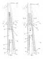
- FIG. 1is a right side perspective view of an intervertebral implant insertion instrument for use in distracting adjacent bony structures such as adjacent spinal vertebrae, and/or for inserting an implant and/or transplant of selected size and shape therebetween, in accordance with one or more embodiments of the present invention
- FIG. 2is a perspective view of the insertion instrument of FIG. 1 with the distraction ramps and implant removed;
- FIG. 3is a perspective view of a portion of the insertion instrument in FIG. 2 , illustrating an implant carried by distraction guides including pair of clamp jaw components at a distal end of an elongated inserter body, in accordance with one or more embodiments of the present invention
- FIG. 4is a perspective view of the insertion instrument of FIG. 2 , depicting an implant being grasped by the clamp jaw components, in accordance with one or more embodiments of the present invention
- FIG. 5is a perspective view of the insertion instrument of FIG. 4 showing the sliding removable mounting of the distraction ramps into the distraction guides, in accordance with one or more embodiments of the present invention
- FIG. 6is an elevational view of the front of the insertion instrument of FIG. 5 , in accordance with one or more embodiments of the invention.
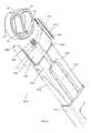
- FIG. 7is a perspective view of the distal end of the inserter of FIG. 4 showing the slideable, removable distraction ramps in an advanced position in relation to the distraction guides, in accordance with one or more embodiments of the present invention
- FIG. 8is a side view of a portion of the insertion instrument of FIG. 7 , in which the ramp units are in an advanced position, with the distal tips of the ramps inserted into an intervertebral cavity between adjacent vertebral bodies, in accordance with one or more embodiments of the present invention
- FIG. 9is side view of a portion of the insertion instrument of FIG. 8 in which the distraction guides have been advanced toward the intervertebral cavity, thereby distracting the vertebral bodies, in accordance with one or more embodiments of the present invention
- FIG. 10is a side view of a portion of the insertion instrument of FIG. 9 in which the distraction guides have been advanced to a final position in relation to the vertebral bodies and the distraction ramps, in accordance with one or more embodiments of the present invention
- FIG. 11is a side view along the elongated midline of the insertion instrument of FIG. 8 , illustrating the lesser height of the implant in relation to the combined height of the ramp tips and distraction guide, in accordance with one or more embodiments of the present invention
- FIG. 12is a side elevational view of the insertion instrument depicting the retraction of a tube member with respect to the ramps and the resulting decrease in the combined height of the distraction ramps in accordance with one or more embodiments of the present invention
- FIG. 13is a side view of the insertion instrument of FIG. 12 showing the engagement of an implant having a height that is greater than the combined height of the distraction ramps and distraction guides, in accordance with one or more embodiments of the invention;
- FIG. 14is an elevational view of the insertion instrument of FIG. 13 from a vantage point at the left side of the view of FIG. 13 that shows the distraction guide, implant and clamp jaw components, wherein the guide and jaw components are in an laterally outward position and wherein the distance between the upper and lower outer surfaces of the distraction ramps is less than the thickness of the implant, in accordance with one or more embodiments of the present invention;
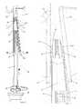
- FIG. 15is an exploded perspective view of the insertion instrument of FIG. 1 and an implant suitable for insertion therewith, in accordance with one or more embodiments of the present invention
- FIG. 16is a perspective view of an implant insertion instrument for use in distracting adjacent bony structures such as adjacent spinal vertebrae, and for inserting an implant and/or transplant of selected size and shape therebetween, in accordance with one or more alternative embodiments of the present invention
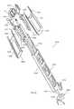
- FIG. 17is an exploded perspective view of the insertion instrument of FIG. 16 , in accordance with one or more embodiments of the present invention.
- FIG. 18is a perspective view of a portion of the insertion instrument and implant of FIG. 16 , with the distraction ramp elements hidden to illustrate the clamp jaw mechanism and the implant, in accordance with one or more alternative embodiments of the present invention
- FIG. 19is a perspective view of an implant insertion instrument for use in distracting adjacent bony structures such as adjacent spinal vertebrae, and for inserting an implant and/or transplant of selected size and shape there between, in accordance with one or more alternative embodiments of the present invention
- FIG. 20is an exploded perspective view of the insertion instrument and implant of FIG. 19 ;
- FIG. 21is a close-up perspective view of a portion of the insertion instrument and implant of FIG. 19 , with the distraction ramp elements hidden to illustrate the threaded engagement mechanism and the implant, in accordance with one or more embodiments of the present invention
- FIG. 22is a perspective view of an implant insertion instrument for use in distracting adjacent bony structures such as adjacent spinal vertebrae, and for inserting an implant and/or transplant of selected size and shape therebetween, with the distraction ramp elements hidden to demonstrate the threaded engagement mechanism and the implant, in accordance with one or more alternative embodiments of the present invention
- FIG. 23is an elevational view of the distal end of the insertion instrument and implant of FIG. 22 , demonstrating a compound distraction angle suitable for anterior lateral implant insertion, in accordance with one or more embodiments of the present invention
- FIG. 24is a plan view of a portion of the insertion instrument and implant of FIG. 22 along with a vertebral body, depicting an anterior-lateral approach to implant insertion, in accordance with one or more embodiments of the present invention
- FIG. 25is an elevational view of a side of the insertion instrument of FIG. 22 employing an anterior-lateral approach to implant insertion, and showing the distraction guide in a final position in relation to the vertebral bodies and the distraction ramps, in accordance with one or more embodiments of the present invention.
- FIG. 26is an elevational view of a side of the insertion instrument of FIG. 25 , showing the engagement of an implant having a height greater than the combined height of the distraction ramps and the guides, in accordance with one or more embodiments of the present invention.
- FIG. 1is a right side perspective view of an intervertebral implant insertion instrument 10 for use in distracting adjacent bony structures such as adjacent spinal vertebrae V 1 and V 2 , and/or for inserting an implant G and/or transplant of selected size and shape therebetween, in accordance with one or more embodiments of the present invention.
- the insertion instrument 10 and related implant Gmay be adapted for use in spinal surgical procedures for placement of the implant G into a distracted intervertebral space wherein the implant G may subsequently serve as a load bearing spacer element for maintaining a prescribed spacing between adjacent vertebral structures (or “vertebrae”) V 1 and V 2 .
- the implant Gmay be formed from a relatively sturdy and biocompatible material such as (but not limited to) a selected metal or metal alloy, bone, polymer, carbon fiber-reinforced polymer and/or ceramic.
- the implant Gmay be formed with a partially open or porous configuration and may be coated or partially filled with a selected bone ingrowth-enhancing substance, such as autogenous bone material harvested from the patient, with transplantable allogenic bone material supplied by a third party donor.
- a selected bone ingrowth-enhancing substancesuch as autogenous bone material harvested from the patient, with transplantable allogenic bone material supplied by a third party donor.
- Such deviceswhen implanted into the intervertebral space, may promote ingrowth of blood supply and live bone cells from the adjacent spinal vertebrae V 1 , V 2 to inter-knit with the implant G, thereby eventually immobilizing or fusing the adjacent spinal vertebrae V 1 , V 2 .
- insertion instrument 10may include handle 40 which may include impaction cap 42 at its proximal end, base component 12 , tube component 16 which may include flange 18 , and knob 20 which may include internal threads 62 ( FIG. 15 ) and which may rotate about shaft 60 having threads 14 .
- Base 12may include slideable arms 22 which may have angled faces 48 , which arms 22 may in turn move distraction guides 36 .
- insertion instrument 10may further include distraction guides 36 , which may in turn include angled faces 44 , grooves 38 , flat face(s) 50 for contacting an implant, and/or clamp components 46 .
- insertion instrument 10may further include distraction ramps (or simply “ramps”) 24 , which may in turn include stopper (or “stop”) 26 , distraction faces 28 , angled faces 30 , flanges 32 , and/or depth stops 34 .
- One or more embodiments of the present inventionmay be operable to insert an implant G into an interbody cavity while avoiding imparting any compressive force, or shear force, to the implant until the implant is located in its final position in an interbody cavity, which may be an intervertebral cavity.
- one or more embodiments of the present inventionmay enable the insertion instrument 10 to be extracted from the interbody cavity without being subjected to compressive or shear forces from the adjacent bodies during such extraction. Avoidance of such compressive and/or shear forces may enable avoiding damage to the adjacent bodies and/or to the insertion instrument.
- one or more embodiments of the present inventionmay be operable to maintain an initial angle between the ramps 24 of insertion instrument 10 during expansion of the interbody cavity, thereby enabling maintenance of a constant lordotic angle between the adjacent bodies being separated by insertion instrument 10 . Further, once the implant G is in a final position between the adjacent bodies, one or more embodiments of the present invention may be operable to gradually transfer the compressive force, urging the adjacent bodies together, from the ramps 24 and distraction guides 36 to the implant, thereby avoiding any sudden undesirable impact forces upon either the implant G or the either or the adjacent bodies.
- Insertion instrument 10may include one or more ramps 24 , which may slide with respect to a mating surface on distraction guides 36 , and which may be configured for quickly and easily distracting, or separating, an interbody cavity between two adjacent bodies, or more particularly, an intervertebral cavity between two adjacent vertebral bodies.
- insertion instrument 10may operate to distract an intervertebral cavity (such as between V 1 and V 2 in FIG. 8 ) at a substantially optimized insertion and distraction angle for facilitated placement of the implant G having a height selected from a range of different heights according to individual patient requirements.
- insertion instrument 10may protect the implant G against substantial compression and/or shear forces during intervertebral distraction and implant placement into the intervertebral cavity or “intervertebral space”.
- instrument 10may include at least one removable distraction guide 36 which may include a pair of clamp components 46 for securely supporting and retaining the implant G during intervertebral placement.
- Insertion instrument 10may further include a tube mechanism, or simply “tube”, 16 which may be operationally coupled to the clamp components 46 for quickly and easily releasing the implant G within the intervertebral space.
- FIGS. 1-5 and 15depict stages of a method for setting up instrument 10 prior to insertion of the implant G in accordance with one or more embodiments of the present invention.
- a pair of distraction guides 36may be removably mounted to a pair of slideable arms 22 .
- Distraction guides 36may be shaped and sized to correspond with the size and shape of a specific implant G which may be selected for a particular insertion operation.
- Distraction guides 36may configured to match the size and shape of a wide range of possible implants G.
- a portion of base 12 of insertion instrument 10may include guide pins 52 which may mate with holes 54 of slideable arms 22 .
- Base 12may further include holes 58 into which springs 56 may be mounted.
- Base 12may further include post 60 .
- knob 20may include internal threads 62 which may engage threads 14 of post 60
- handle 40may include internal threads 64 .
- arms 22may move laterally in relation to the base 12 . Otherwise stated, arms 22 may move within a plane parallel to the plane of the serrated upper and lower surfaces of implant G in the view of FIG. 15 . Arms 22 may move employing sliding contact with adjacent surfaces, or alternatively using a roller interface, or other suitable mechanism for movement of arms 22 with respect to surfaces remaining stationary within insertion instrument 10 . Guide pins 52 on the laterally inward side of arms 22 may reside within holes 54 on the base 12 to enable the laterally directed motion of the arms 22 . A pair of springs 56 ( FIG. 15 ) may be positioned within a second set of lateral holes 58 in the base 12 . This arrangement of springs 56 serve to force the arms 22 , and thereby the distraction guides 36 , out laterally in the absence of any opposing force.
- tube 16may move with respect to base 12 along a longitudinal axis thereof to either open (expand)_ or close (contract) arms 22 .
- Motion of the tube 16 with respect to the base 12may be effected by rotating threaded knob 20 in the desired direction.
- Knob 20may have internal threads 62 that mate with threads 14 on shaft 60 on the body 12 .
- Tube 16may include a cylindrical flange 18 at the proximal end thereof, which may operate to maintain a constant linear distance between the knob 20 and the tube 16 .
- knob 20may advance or retract the tube 16 into the desired position with respect to tube 12 .
- the internal edges of the tube 16may engage the angled faces 48 of the arms 22 , thereby bringing the arms together and causing the distraction guides 36 to grasp the implant G.
- the knob 20 and the tube 16may be prevented from retracting too far by threading the handle 40 onto the rear of the body 12 using internal threads 64 of the handle 40 .
- distraction guides 36may be removably attached to slideable arms 22 .
- distraction guides 36may track the movement of the arms 22 .
- the clamps 46 of the distraction guides 36may make contact with the lateral walls of the implant G to hold the implant G in place.
- the flat face 50 of the distraction guides 36may press against a proximal wall portion (the portion facing toward instrument 10 ) of the implant G to ensure proper positioning of the implant.
- the medial face (inner face) of the guides 36may include one or more grooves 38 and/or one or more angled faces 44 .
- the angled faces 44 of the distraction guides 36may form portions of V-shaped surfaces for engaging corresponding surfaces on ramps 24 .
- each distraction guide 36may include one upper slanted surface and one lower slanted surface 44 for engaging respective surfaces of ramps 24 .
- the upper and lower faces 44 of distraction guides 36may be oriented at a generally lordotic angle with respect to one another, which arrangement may cause the longitudinal axes of the upper and lower ramps 24 to also be oriented at this lordotic angle with respect to one another.
- Each of grooves 38 and faces 44 of the distraction guides 36may extend along an axis corresponding to the proximal-distal axis of a corresponding ramp 24 .
- the foregoingmay apply to both the upper groove 38 and face 44 and the lower groove 38 and face 44 of each distraction guide 36 .
- Each edge of each ramp 24may include a flange 32 and angled face 30 corresponding to the groove 38 and face 44 , respectively, of the distraction guide 36 with which the ramp 24 edge interfaces.
- the flange 32 of each ramp 24 and the groove of the corresponding distraction guide 36may slide with respect to one another as the ramps 24 move with respect to the distraction guides 36 .
- the angled faces 30 of the ramps 24may be shaped so as to form a portion of a V-shaped surface with the point of the “V” pointed towards the implant G.
- the ramps 24may be slid forward until the stops 26 of the ramps 24 make contact with respective rear portions (portions facing the proximal end of the instrument 10 ) of the guides 36 , as shown in FIG. 7 .
- Advancing the ramps 24 with respect to the distraction guides 36 in this mannermay operate to present a thinner profile for instrument 10 , and a more acute angle between (the longitudinal axes of) the ramps 24 .
- This more acute angle between ramps 24may enable the insertion instrument 10 to more effectively advance into a space between adjacent bodies, such as adjacent vertebrae, and to create an initial interbody cavity prior to expanding this interbody cavity via movement of the distraction guides with respect to the ramps 24 .
- FIG. 6depicts the interaction between the implant G, the distraction guides 36 , and the ramps 24 , in accordance with one or more embodiments of the present invention.
- the angled faces 44 of the guides 36 and angled faces 30 of the ramps 24may contact one another. More specifically, the ramps 24 may move atop (in the case of the upper ramp 24 ) the angled face 44 of the distraction guides 36 .
- the distraction guides 36are in the medial (inward) position, and may thereby operate to grasp the implant G.
- the guides 36may operate to resist any compressive force operating to urge the ramps 24 together and to thereby avoid loading implant G with any of the compressive force.
- the overall height of the ramps 24may be determined by the position of the distraction guides 36 with respect to the ramps 24 along the lateral axis of the body 12 (the axis from left to right in the view of FIG. 6 ).
- the ramps 24may include distraction faces 28 on the outer surfaces thereof (the surfaces being configured to contact the adjacent bodies such as vertebral bodies).
- the distraction faces 28may have surfaces that are roughened in some manner, with one or more of serrations, knurling, chemical etching, and/or other surface modifications.
- the distance between the distraction faces 28 of the ramps 24may be greater than the thickness of the implant G, which may enable the ramps 24 and the guides 36 to receive the entirety of the compressive force urging adjacent bodies together, thereby shielding the implant from this compressive force during the implant insertion process.
- the thickness of the implant Gmay be less than the distance between the inner surfaces of the ramps 24 , thereby allowing the ramps to slide over the implant without contacting it.
- FIGS. 8-14depict various stages of insertion of the implant G between a pair of vertebral bodies V 1 and V 2 by the insertion instrument 10 , in accordance with one or more embodiments of the present invention.
- the ramps 24are in the most extended position with respect to the distraction guides 36 along the longitudinal axis of insertion instrument 10 .
- the distraction guides 36may be in the medial (inward) position as shown in FIG. 6 .
- the distraction guides 36may be maintained in this medial (inward) position by placing the tube 16 in its most forward or distal position with respect to the body 12 .
- the combined height of the ramps 24may only slightly exceed that of the implant G.
- the insertion instrument 10may be advanced toward a surgical site leading with the ramps 24 .
- the distal tips of the ramps 24may be inserted into an intervertebral cavity between a pair of vertebral bodies V 1 and V 2 until the depth stops 34 contact the anterior surfaces (the surface facing toward the proximal end of insertion instrument 10 ) of the vertebral bodies V 1 and V 2 .
- the entry of the ramps into the intervertebral cavitymay be facilitated by maintaining a lordotic angle between the ramps 24 using the distraction guides 36 .
- ramps 24may be prevented from undesirably retracting from the intervertebral cavity by virtue of the presence of frictional forces between distraction faces 28 on the tips of the ramps 24 and the surfaces of the adjacent vertebrae contacting surfaces 28 .
- the body 12 of the device 10may be advanced toward the vertebral bodies V 1 and V 2 by impacting the impaction cap 42 , which may be located at the proximal end of the handle 40 .
- this distractionmay be accomplished by moving the distraction guides 36 distally along the longitudinal axis of insertion instrument 10 , with respect to the ramps 24 to separate the ramps 24 . As the instrument 10 advances, the distraction guides 36 may advance therewith. The grooves 38 on the medial (inward) side of the distraction guides 36 may slide along the flanges 32 of the ramps 24 .
- the compressive force urging the adjacent vertebral bodies together(which may also be referred to herein as the “load”) may be transferred through the ramps 24 to the distraction guides 36 .
- the above-described approachwhich enables the distraction guides 36 to receive all or at least substantially all of the compressive force urging the adjacent bodies together, may enable the system and method of the present invention to avoid loading the implant with any of the compressive force from the interbody cavity during the insertion of the implant into the interbody cavity.
- the advancement of the distraction guides 36 with respect to the ramps 24 distally along the longitudinal axis of the instrument 10may operate to separate the ramps 24 while maintaining the angle between the ramps constant.
- the angle between the ramps 24 that is being held constantis the lordotic angle suitable for the particular insertion process being conducted.
- the preservation of the angle between the ramps 24 during the insertion processmay cause the lordotic angle between the surfaces of the bodies V 1 and V 2 contacted by the ramps 24 to also remain constant throughout the implant insertion process.
- the above-described approachmay provide parallel distraction of bodies V 1 and V 2 while preserving the desired lordotic angle between the bodies V 1 and V 2 .
- This approachcontrasts with existing approaches in which ramps or levers pivot about a common fulcrum, or about separate fulcrums, in which the angle between the surfaces of the intervertebral cavity is not maintained constant throughout the implant insertion process.
- FIGS. 10 and 11show the instrument 10 in the fully distracted position with the distraction guides 36 and implant G fully advanced into the intervertebral cavity, in accordance with one or more embodiments of the invention.
- the ramps 24may be fully distracted.
- the implant Gmay be located in a desired final location between the adjacent vertebral bodies.
- the distance between the respective distraction faces 28 of the two ramps 24may be slightly greater than the height of the implant G, thereby enabling the serrated faces G 1 and G 2 of the implant G to be free from contact with the vertebral bodies V 1 and V 2 .
- implant Gmay still be free of compressive force from the intervertebral bodies V 1 and V 2 .
- FIGS. 12-14demonstrate the final positioning of the implant G and the release of the implant G by the instrument 10 , in accordance with one or more embodiments of the present invention.
- the tube component 16may be retracted with respect to the body 12 of instrument 10 toward the proximal end of instrument 10 .
- the retraction of tube 12may be accomplished by rotating the knob 20 which may cause the tube 16 to move linearly toward the proximal end of instrument 10 and away from the vertebrae V (where “V” refers to the V 1 and V 2 together).
- the internal springs 56may cause the arms 22 to move out laterally away from a longitudinal center of instrument 10 , which in turn may cause the distraction guides 36 to move out laterally as well.
- the lateral motion of the distraction guides 36 away from the center of instrument 10may cause distraction guides to stop receiving, or otherwise stated, to stop resisting the compressive force imparted by the adjacent bodies V 1 and V 2 .
- the compressive force from the adjacent bodieswhich may no longer be opposed by the distraction guides, 36 may cause the ramps 24 to move toward each other, thereby enabling the vertebral bodies V 1 and V 2 to do the same.
- the ramps 24may comply with the unopposed compressive force from the adjacent bodies and approach one another by moving into the expanding space between the laterally displaced distraction guides 36 .
- the approach of the ramps towards one anothermay continue until the distance between the outer ramp 24 surfaces is less than the thickness (or “height”) of the implant G.
- the compressive force urging the adjacent bodies V 1 and V 2 togethermay be gradually transferred from the ramps 24 to the implant G.
- the serrated faces G 1 and G 2 of the implant Gmay engage, or bite into, the endplates (implant-facing surfaces) of the corresponding vertebral bodies V 1 and V 2 , as the upper and lower bodies V 1 and V 2 are urged together toward the upper and lower surfaces, respectively, of the implant G.
- the above-discussed approachmay enable the gradual transfer of the compressive force from the ramps 24 to the implant G and may enable the implant G to be securely held in place during the release of the implant by the instrument 10 and during the extraction of the instrument 10 from the intervertebral cavity.
- the above-discussed approachmay also enable the instrument 10 to be extracted from the intervertebral cavity without the application of a compressive force thereon. Freeing the instrument from the compressive force in this manner, may help avoid damage to the instrument and/or to the implant during the instrument extraction.
- the ability to extract the instrument 10 from the interbody cavity while free of the application of compressive force from bodies V 1 and V 2may be enabled by the shape of one or more embodiments of the distal portions of ramps 24 , as best seen in FIG. 1 .
- the tangs or “finger portions” of the upper ramp 24clear the edges of the implant along the plane of the upper surface of the implant.
- the ramp 24 tangsmay move vertically along the sides of the implant G instead of coming to rest on the upper and lower surfaces of the implant G. In this manner, the ramp 24 tangs may avoid getting caught between the vertebral bodies and the implant G, as the vertebral bodies come to rest.
- FIGS. 16-18depict a method for setting up an instrument 1610 prior to insertion of the implant G 3 in accordance with one or more alternative embodiments of the present invention.
- a pair of distraction guides 1636may be removably mounted to a pair of slideable arms 1622 .
- the distraction guides 1636may be shaped and sized to correspond with the size and shape of a particular implant G 3 which has been chosen by a surgeon to conform to an individual patient's anatomy.
- Various embodiments of the distraction guides 1636may be available to match various respective implants G 3 .
- the slideable arms 1622may move laterally inward or outward in relation to the base 1612 , as discussed in connection with the embodiments of FIGS. 1-15 . With reference to FIG.
- guide pins 1652 on the medial (inward) side of the arms 1622may be located within holes 1654 on the base 1612 to enable the lateral motion of the arms 1622 .
- a pair of springs 1656may be positioned within a second set of lateral holes 1658 in the base 1612 . Springs 1656 may operate to force the arms 1622 , and thereby the distraction guides 1636 , laterally outward from base 1612 .
- Tube 1616may move along base 1612 employing sliding contact, rolling contact, or other suitable motion interface.
- the motion of the tube 1616may be controlled by rotating threaded knob 1620 , as discussed in connection with other embodiments herein.
- the knob 1620may include internal threads 1662 that mate with external threads 1614 located on a shaft 1660 extending from the base (or “body”) 1612 .
- a cylindrical flange 1618 at the proximal end of the tube 1616may be operable to maintain a constant linear distance between the knob 1620 and the tube 1616 .
- the above described arrangementmay enable rotation of the knob 1620 to move the tube 1616 to a desired position with respect to the body 12 .
- Distal movement of the tube 1616may be operable to force the slideable arms 1622 toward a laterally inward position.
- the inside edges of the tube 1616may engage the angled faces 1648 of the arms 1622 , thereby pushing the arms 1622 into a laterally inward position.
- the knob 1620 and the tube 1616may be prevented from retracting too far with respect to the body 1612 by causing the internal threads 1664 of handle 1640 to engage the external threads 1614 of the body 1612 .
- distraction guides 1636may be removably attached to the slideable arms 1622 , distraction guides 1636 may move laterally along with arms 1622 .
- a pair of grasping jaws 1668may be provided which may move within a cutout 1672 of the guides 1636 .
- Grasping jaws 1668may also have an angled face 1670 which is engaged by the tube 1616 , as the tube 1616 advances distally with respect to the base 1612 . As the jaws 1668 move laterally inward, the inner walls 1646 of jaws 1668 may press against the grooves G 4 of the implant G 3 to securely grasp the implant and to hold the implant in place.
- the flat faces 1650 of the guides 1636may press against the proximal wall (the wall of the implant facing the proximal end of the instrument 1610 ) of the implant G 3 to ensure proper positioning of the implant.
- the distraction guides 1636may also be moved laterally inward by the tube component 1616 , and the ramps 1624 can be slid into position.
- the implant G 3which may have larger tolerances than the instrument 1610 , may be securely grasped with greater reliability.
- the instrument 1610may conduct the implant G 3 insertion operation and subsequent extraction of the insertion instrument 1610 in much the same manner as described in connection with FIGS. 8-14 .
- FIGS. 19-21depict a method for setting up yet another embodiment of an insertion instrument, instrument 1910 , prior to insertion of an implant G 5 into an interbody cavity, in accordance with one or more embodiments of the present invention.
- a pair of distraction guides 1936may be removably mounted to a pair of slideable arms 1922 .
- the distraction guides 1936may be shaped and sized to accommodate the size and shape of a particular implant G 5 which has been chosen by a surgeon to suit a particular patient's anatomy.
- a plurality of distraction guides 1936may have dimensions that are customized to match various respective implants G 5 .
- the slideable arms 1922may move laterally inward and outward in relation to the base 1912 .
- guide pins 1952 on the medial side of the arms 1922may be located within holes 1954 on the base 1912 to enable the lateral motion of the arms 1922 .
- a pair of springs 1956may be positioned within a second set of lateral holes 1958 in the base 1912 . Springs 1956 may operate to force the arms 1922 , and thereby the distraction guides 1936 , laterally outward from base 1912 .
- Tube 1916may move along base 1912 employing sliding contact, rolling contact, or other suitable motion interface.
- the tube 1916may be locked into place using a locking arm 1920 .
- the locking arm 1920may create a friction lock between the base 1912 and the tube 1916 .
- Movement of the tube 1916may be operable to force the slideable arms 1922 toward a laterally inward position.
- the inside edges of the tube 1916may engage the angled faces 1948 of the arms 1922 , thereby pushing the arms 1922 into a laterally inward position.
- the tube 1916may be prevented from retracting too far with respect to the body 1912 by inserting the small post 1960 that protrudes from body 1912 into the internal bore 1964 of handle 1940 .
- the implant G 5may be attached to the inserter 1910 by means of an elongated shaft 1914 .
- the shaft 1914may extend through the entire body 1912 and handle 1940 of the instrument 1910 .
- the shaft 1914may include a threaded tip 1918 , at the distal end thereof, that may engage the implant G 5 by means of a threaded hole G 6 on the proximal side of the implant.
- the shaft 1914may be rotated by a knob 1942 at the proximal end of the shaft 1914 . Since the distraction guides 1936 may be removably attached to the slideable arms 1922 , as the arms 1922 move laterally inward and outward, the distraction guides 1936 may move along with the arms 1922 .
- the inner faces 1950 of guides 1936may press against the perimeter of the implant G 5 and may thereby hold the implant in place.
- the ramps 1924can be slid into position. The processes of a) assembling the ramps 1924 to the instrument 1910 and b) the subsequent insertion of the implant G 5 within an intervertebral cavity are similar to what was discussed in connection with FIGS. 5-14 . Accordingly, that discussion is not repeated in this section.
- FIG. 22-26depict yet another embodiment of the insertion device 2210 , in accordance with various aspects of the invention, for placing an implant G 5 between two adjacent vertebral bodies V 1 and V 2 from an anterior-lateral, or oblique, approach.
- the direction of insertion of implant G 5may be at a non-zero angle with respect to the longitudinal axis of the insertion instrument 2210 about an axis perpendicular the planes of the upper and lower surfaces of implant G 5 .
- the non-zero anglemay be between 10 and 90 degrees. In one or more other embodiments, the non-zero angle may be between 15 and 45 degrees.
- any non-zero angle between the direction of insertion and the longitudinal axes of insertion instrument 10may be employed.
- two distraction guides 2220 and 2236may be removably mounted to two respective slideable arms 2222 .
- Distraction guides 2220 and 2236may be shaped and sized to correspond with the size and shape of a particular implant G 5 which has been chosen by a surgeon to conform to a particular patient's anatomy.
- Various implementations of the distraction guides 2220 and 2236may be made available to match various respective specific implants G 5 .
- distraction guides 2220 and 2236may be designed to enable the implant G 5 to be inserted from an anterior-lateral approach while maintaining the appropriate sagittal alignment of the spine.
- the vertebral bodiesmay be distracted at the appropriate sagittal angle.
- the sagittal angle of distraction between the vertebral bodiesthat may be provided by the above combination may be best seen in FIGS. 25 and 26 .
- tube 2216may move along base 2212 employing sliding contact, rolling contact, or other suitable motion interface. Once the tube 2216 is in a desired position with respect to the base 2212 , the tube 2216 may be locked into place using a locking arm, such as locking arm 1920 shown in FIG. 19 . Motion of the tube 2216 with respect to the base 2212 may be operable to control the position of the slideable arms 2222 and the distraction guides 2220 and 2236 . In one or more embodiments, as the tube 2216 moves toward the implant G 5 , the inside edges of the tube 2216 may engage the angled faces 2248 of the arms 2222 , thereby pushing the arms 2222 into a laterally inward position.
- the implant G 5may be attached to the insertion instrument 2210 by means of an elongated shaft 2214 .
- Shaft 2214may extend through the entire body 2212 of the insertion instrument 2210 .
- Shaft 2214may include a threaded tip 2218 , at the distal end of shaft 2214 , that may thread into the implant G 5 by means of a threaded hole G 7 on the anterior-lateral face (a face of the implant G 5 facing the proximal end of the instrument 2210 ) of the implant G 5 .
- the distraction guides 2220 and 2236may be removably attached to the slideable arms 2222 . Accordingly, as the arms 2222 move laterally, the distraction guides 2220 and 2236 may move laterally along with the arms 2222 . As the distraction guides 2236 move laterally inward, the inner wall 2250 of each distraction guide 2220 , 2236 may contact the perimeter of the implant G 5 and may thereby operate to hold the implant in place. Once the implant G 5 is securely held by the threaded shaft 2214 , the ramps 2224 can be slid into position. Because of the compound angle ⁇ of the grooves 2238 and 2230 and angled faces 2244 and 2232 , the ramps 2224 are likewise held at this angle ⁇ .
- FIG. 24depicts the instrument 2210 and implant G 5 on a vertebral body V 2 from an anterior lateral approach, in accordance with one or more embodiments of the present invention. It is noted that that the implant G 5 may be in the same orientation it would have been in, had the implant G 5 been implanted from a straight anterior approach, in which the insertion direction and the longitudinal axis of the insertion instrument 10 are aligned. Proper orientation of the implant during the insertion process may be beneficial in ensuring that the proper sagittal alignment of the spine is maintained during and after insertion of the implant G 5 .
- FIG. 24further shows threaded tip 2218 protruding through the sidewall of the implant G 5 . As the insertion progresses into the intervertebral cavity above the vertebral body V 2 , depth stops 2234 of the ramps 2224 may engage the anterior lateral face of the body V 2 .
- FIG. 25shows the device 2210 in the fully distracted position between the vertebral bodies V 1 and V 2 with the distraction guide 2236 and the implant G 5 fully advanced into the intervertebral cavity.
- the ramps 2224may be fully distracted.
- the implant G 5may be located at a desired final location between the adjacent vertebral bodies.
- the distance between the respective distraction faces 2228 of the two ramps 2224may be slightly greater than the height of the implant G 5 , thereby enabling the serrated faces G 8 and G 9 to be free from contact with the vertebral bodies V 1 and V 2 .
- implant G 5may still not have experienced any compressive force from the vertebral bodies.
- the ramps 2224may be distracted while being maintained at a constant sagittal angle with respect to one another. It is noted that that the combination of these angles may match the lordotic angle between the upper and lower contact surfaces of implant G 5 as well.
- FIG. 26demonstrates the final positioning of the implant G 5 and the release of the implant G 5 by the instrument 2210 , in accordance with one or more embodiments of the present invention.
- the tube 2216may be retracted with respect to the body 2212 of instrument 2210 .
- internal springsmay cause the arms 2222 to move out laterally, which may in turn cause the distraction guides 2220 and 2236 to move out laterally as well.
- the outward lateral motion of the distraction guides 2220 and 2236may cause the distraction guides 2220 and 2236 to stop receiving, or otherwise stated, to stop resisting the compressive force imparted by the adjacent vertebral bodies V 1 and V 2 .
- the compressive force from the adjacent bodies V 1 and V 2may cause the ramps 2224 to approach one another, thereby enabling the vertebral bodies V 1 and V 2 approach one another as well.
- the ramps 2224may comply with the compressive force from the adjacent bodies and move into the expanding space between the laterally displaced distraction guides 2220 and 2236 .
- the approach of the ramps toward one anothermay continue until the distance between the outer surfaces 2228 of the ramps 2224 is less than the height of the implant G 5 .
- the compressive force urging the bodies V 1 and V 2 togethermay be gradually transferred from the ramps 2224 to the implant G 5 .
- the serrated faces G 8 and G 9 of the implant G 5may engage, or bite into, the endplates (the implant-facing surfaces) of the vertebral bodies V 1 and V 2 .
- the above-described gradual transfer of compressive forcemay enable the implant G 5 to remain in a desired final location between the bodies V 1 and V 2 without being unintentionally dislodged by the extraction of the insertion instrument 2210 .
- the shaft 2214may be unthreaded from the implant hole G 7 .
- insertion instrument 2210may be removed from the interbody cavity with the implant G 5 located in the desired position with respect to the vertebral bodies V.
- various characteristics of insertion instrument 2210may enable instrument 2210 to be free of any compressive force from the bodies V 1 and V 2 during the extraction thereof from the interbody cavity (in this case, an intervertebral cavity).
Landscapes
- Health & Medical Sciences (AREA)
- Engineering & Computer Science (AREA)
- Biomedical Technology (AREA)
- Orthopedic Medicine & Surgery (AREA)
- Transplantation (AREA)
- Neurology (AREA)
- Oral & Maxillofacial Surgery (AREA)
- Cardiology (AREA)
- Heart & Thoracic Surgery (AREA)
- Vascular Medicine (AREA)
- Life Sciences & Earth Sciences (AREA)
- Animal Behavior & Ethology (AREA)
- General Health & Medical Sciences (AREA)
- Public Health (AREA)
- Veterinary Medicine (AREA)
- Physical Education & Sports Medicine (AREA)
- Prostheses (AREA)
Abstract
Description
Claims (6)
Priority Applications (2)
| Application Number | Priority Date | Filing Date | Title |
|---|---|---|---|
| US13/246,297US8382768B2 (en) | 2006-08-16 | 2011-09-27 | Apparatus and methods for inserting an implant |
| US13/777,435US8801721B2 (en) | 2006-08-16 | 2013-02-26 | Apparatus and methods for inserting an implant |
Applications Claiming Priority (3)
| Application Number | Priority Date | Filing Date | Title |
|---|---|---|---|
| US82261306P | 2006-08-16 | 2006-08-16 | |
| US11/622,545US8062303B2 (en) | 2006-08-16 | 2007-01-12 | Apparatus and methods for inserting an implant |
| US13/246,297US8382768B2 (en) | 2006-08-16 | 2011-09-27 | Apparatus and methods for inserting an implant |
Related Parent Applications (1)
| Application Number | Title | Priority Date | Filing Date |
|---|---|---|---|
| US11/622,545DivisionUS8062303B2 (en) | 2006-08-16 | 2007-01-12 | Apparatus and methods for inserting an implant |
Related Child Applications (1)
| Application Number | Title | Priority Date | Filing Date |
|---|---|---|---|
| US13/777,435ContinuationUS8801721B2 (en) | 2006-08-16 | 2013-02-26 | Apparatus and methods for inserting an implant |
Publications (2)
| Publication Number | Publication Date |
|---|---|
| US20120029642A1 US20120029642A1 (en) | 2012-02-02 |
| US8382768B2true US8382768B2 (en) | 2013-02-26 |
Family
ID=39082846
Family Applications (3)
| Application Number | Title | Priority Date | Filing Date |
|---|---|---|---|
| US11/622,545Expired - Fee RelatedUS8062303B2 (en) | 2006-08-16 | 2007-01-12 | Apparatus and methods for inserting an implant |
| US13/246,297Expired - Fee RelatedUS8382768B2 (en) | 2006-08-16 | 2011-09-27 | Apparatus and methods for inserting an implant |
| US13/777,435ActiveUS8801721B2 (en) | 2006-08-16 | 2013-02-26 | Apparatus and methods for inserting an implant |
Family Applications Before (1)
| Application Number | Title | Priority Date | Filing Date |
|---|---|---|---|
| US11/622,545Expired - Fee RelatedUS8062303B2 (en) | 2006-08-16 | 2007-01-12 | Apparatus and methods for inserting an implant |
Family Applications After (1)
| Application Number | Title | Priority Date | Filing Date |
|---|---|---|---|
| US13/777,435ActiveUS8801721B2 (en) | 2006-08-16 | 2013-02-26 | Apparatus and methods for inserting an implant |
Country Status (3)
| Country | Link |
|---|---|
| US (3) | US8062303B2 (en) |
| EP (1) | EP2051660B1 (en) |
| WO (1) | WO2008021645A2 (en) |
Cited By (11)
| Publication number | Priority date | Publication date | Assignee | Title |
|---|---|---|---|---|
| US8702719B2 (en)* | 2008-10-16 | 2014-04-22 | Aesculap Implant Systems, Llc | Surgical instrument and method of use for inserting an implant between two bones |
| US9034046B2 (en) | 2007-10-30 | 2015-05-19 | Aesculap Implant Systems, Llc | Vertebral body replacement device and method for use to maintain a space between two vertebral bodies within a spine |
| US9192419B2 (en) | 2008-11-07 | 2015-11-24 | DePuy Synthes Products, Inc. | Zero-profile interbody spacer and coupled plate assembly |
| US9220604B2 (en) | 2010-12-21 | 2015-12-29 | DePuy Synthes Products, Inc. | Intervertebral implants, systems, and methods of use |
| US9241809B2 (en) | 2010-12-21 | 2016-01-26 | DePuy Synthes Products, Inc. | Intervertebral implants, systems, and methods of use |
| US9463097B2 (en) | 2003-02-06 | 2016-10-11 | DePuy Synthes Products, Inc. | Intervertebral implant |
| US9572681B2 (en) | 2002-02-19 | 2017-02-21 | DePuy Synthes Products, Inc. | Intervertebral implant |
| US9744049B2 (en) | 2007-11-16 | 2017-08-29 | DePuy Synthes Products, Inc. | Low profile intervertebral implant |
| US9867718B2 (en) | 2014-10-22 | 2018-01-16 | DePuy Synthes Products, Inc. | Intervertebral implants, systems, and methods of use |
| US10512548B2 (en) | 2006-02-27 | 2019-12-24 | DePuy Synthes Products, Inc. | Intervertebral implant with fixation geometry |
| US12318307B2 (en) | 2021-07-16 | 2025-06-03 | Blue Ocean Spine Gmbh | Adjustable spinal implants, associated instruments and methods |
Families Citing this family (164)
| Publication number | Priority date | Publication date | Assignee | Title |
|---|---|---|---|---|
| US7901458B2 (en)* | 2005-12-16 | 2011-03-08 | Warsaw Orthopedic, Inc. | Intervertebral spacer and insertion tool |
| US20080161821A1 (en)* | 2006-10-16 | 2008-07-03 | Warsaw Orthopedic, Inc. | Surgical Tool for Insertion of Spinal Prosthesis |
| US20080161929A1 (en) | 2006-12-29 | 2008-07-03 | Mccormack Bruce | Cervical distraction device |
| US8486081B2 (en)* | 2007-07-23 | 2013-07-16 | DePuy Synthes Products, LLC | Implant insertion device and method |
| WO2009089367A2 (en) | 2008-01-09 | 2009-07-16 | Providence Medical Technology, Inc. | Methods and apparatus for accessing and treating the facet joint |
| US9333086B2 (en) | 2008-06-06 | 2016-05-10 | Providence Medical Technology, Inc. | Spinal facet cage implant |
| EP2361046B1 (en) | 2008-06-06 | 2019-04-24 | Providence Medical Technology, Inc. | Cervical distraction/implant delivery device |
| US8361152B2 (en) | 2008-06-06 | 2013-01-29 | Providence Medical Technology, Inc. | Facet joint implants and delivery tools |
| US11224521B2 (en) | 2008-06-06 | 2022-01-18 | Providence Medical Technology, Inc. | Cervical distraction/implant delivery device |
| CA2725811A1 (en) | 2008-06-06 | 2009-12-10 | Providence Medical Technology, Inc. | Facet joint implants and delivery tools |
| US9381049B2 (en) | 2008-06-06 | 2016-07-05 | Providence Medical Technology, Inc. | Composite spinal facet implant with textured surfaces |
| US8267966B2 (en) | 2008-06-06 | 2012-09-18 | Providence Medical Technology, Inc. | Facet joint implants and delivery tools |
| US8382767B2 (en)* | 2008-10-31 | 2013-02-26 | K2M, Inc. | Implant insertion tool |
| US8992558B2 (en) | 2008-12-18 | 2015-03-31 | Osteomed, Llc | Lateral access system for the lumbar spine |
| US10045860B2 (en) | 2008-12-19 | 2018-08-14 | Amicus Design Group, Llc | Interbody vertebral prosthetic device with self-deploying screws |
| US9474629B2 (en)* | 2009-08-19 | 2016-10-25 | The Governors Of The University Of Alberta | End plate slider/distractor for posterior intervertebral device and method |
| US11564807B2 (en) | 2009-10-15 | 2023-01-31 | Globus Medical, Inc. | Expandable fusion device and method of installation thereof |
| US8685098B2 (en) | 2010-06-25 | 2014-04-01 | Globus Medical, Inc. | Expandable fusion device and method of installation thereof |
| US10327917B2 (en) | 2009-10-15 | 2019-06-25 | Globus Medical, Inc. | Expandable fusion device and method of installation thereof |
| US9216095B2 (en) | 2009-10-15 | 2015-12-22 | Globus Medical, Inc. | Expandable fusion device and method of installation thereof |
| US11344430B2 (en) | 2009-10-15 | 2022-05-31 | Globus Medical, Inc. | Expandable fusion device and method of installation thereof |
| US10098758B2 (en) | 2009-10-15 | 2018-10-16 | Globus Medical, Inc. | Expandable fusion device and method of installation thereof |
| US8062375B2 (en) | 2009-10-15 | 2011-11-22 | Globus Medical, Inc. | Expandable fusion device and method of installation thereof |
| US9155628B2 (en) | 2009-10-15 | 2015-10-13 | Globus Medical, Inc. | Expandable fusion device and method of installation thereof |
| US8556979B2 (en) | 2009-10-15 | 2013-10-15 | Globus Medical, Inc. | Expandable fusion device and method of installation thereof |
| US11103366B2 (en) | 2009-10-15 | 2021-08-31 | Globus Medical, Inc. | Expandable fusion device and method of installation thereof |
| US10806596B2 (en) | 2009-10-15 | 2020-10-20 | Globus Medical, Inc. | Expandable fusion device and method installation thereof |
| US8709086B2 (en)* | 2009-10-15 | 2014-04-29 | Globus Medical, Inc. | Expandable fusion device and method of installation thereof |
| US9480511B2 (en) | 2009-12-17 | 2016-11-01 | Engage Medical Holdings, Llc | Blade fixation for ankle fusion and arthroplasty |
| US8353963B2 (en) | 2010-01-12 | 2013-01-15 | Globus Medical | Expandable spacer and method for use thereof |
| US9913726B2 (en) | 2010-02-24 | 2018-03-13 | Globus Medical, Inc. | Expandable intervertebral spacer and method of posterior insertion thereof |
| US8858636B2 (en) | 2010-04-09 | 2014-10-14 | DePuy Synthes Products, LLC | Intervertebral implant |
| US9301853B2 (en)* | 2010-04-09 | 2016-04-05 | DePuy Synthes Products, Inc. | Holder for implantation and extraction of prosthesis |
| US8870880B2 (en) | 2010-04-12 | 2014-10-28 | Globus Medical, Inc. | Angling inserter tool for expandable vertebral implant |
| US9301850B2 (en) | 2010-04-12 | 2016-04-05 | Globus Medical, Inc. | Expandable vertebral implant |
| US9597200B2 (en) | 2010-06-25 | 2017-03-21 | Globus Medical, Inc | Expandable fusion device and method of installation thereof |
| US9474625B2 (en) | 2010-09-03 | 2016-10-25 | Globus Medical, Inc | Expandable fusion device and method of installation thereof |
| US11446162B2 (en) | 2010-09-03 | 2022-09-20 | Globus Medical, Inc. | Expandable fusion device and method of installation thereof |
| US8632595B2 (en) | 2010-09-03 | 2014-01-21 | Globus Medical, Inc. | Expandable fusion device and method of installation thereof |
| US10842644B2 (en) | 2010-09-03 | 2020-11-24 | Globus Medical, Inc. | Expandable fusion device and method of installation thereof |
| US9907673B2 (en) | 2010-09-03 | 2018-03-06 | Globus Medical, Inc. | Expandable fusion device and method of installation thereof |
| US10709573B2 (en) | 2010-09-03 | 2020-07-14 | Globus Medical Inc. | Expandable fusion device and method of installation thereof |
| US10945858B2 (en) | 2010-09-03 | 2021-03-16 | Globus Medical, Inc. | Expandable interspinous process fixation device |
| US10779957B2 (en) | 2010-09-03 | 2020-09-22 | Globus Medical, Inc. | Expandable fusion device and method of installation thereof |
| US10869768B2 (en) | 2010-09-03 | 2020-12-22 | Globus Medical Inc. | Expandable fusion device and method of installation thereof |
| US10835387B2 (en) | 2010-09-03 | 2020-11-17 | Globus Medical Inc. | Expandable fusion device and method of installation thereof |
| US10758367B2 (en) | 2010-09-03 | 2020-09-01 | Globus Medical Inc. | Expandable fusion device and method of installation thereof |
| US8491659B2 (en) | 2010-09-03 | 2013-07-23 | Globus Medical, Inc. | Expandable fusion device and method of installation thereof |
| US8435298B2 (en) | 2010-09-03 | 2013-05-07 | Globus Medical, Inc. | Expandable fusion device and method of installation thereof |
| US9351848B2 (en) | 2010-09-03 | 2016-05-31 | Globus Medical, Inc. | Expandable fusion device and method of installation thereof |
| US12370057B2 (en) | 2010-09-03 | 2025-07-29 | Globus Medical, Inc. | Expandable fusion device and method of installation thereof |
| US11793654B2 (en) | 2010-09-03 | 2023-10-24 | Globus Medical, Inc. | Expandable fusion device and method of installation thereof |
| US8845732B2 (en) | 2010-09-03 | 2014-09-30 | Globus Medical, Inc. | Expandable fusion device and method of installation thereof |
| US12059358B2 (en) | 2010-09-03 | 2024-08-13 | Globus Medical Inc. | Expandable fusion device and method of installation thereof |
| US10085849B2 (en) | 2010-09-03 | 2018-10-02 | Globus Medical, Inc. | Expandable fusion device and method of installation thereof |
| US10512550B2 (en) | 2010-09-03 | 2019-12-24 | Globus Medical, Inc. | Expandable interspinous process fixation device |
| US9566168B2 (en) | 2010-09-03 | 2017-02-14 | Globus Medical, Inc. | Expandable fusion device and method of installation thereof |
| US9855151B2 (en) | 2010-09-03 | 2018-01-02 | Globus Medical, Inc | Expandable fusion device and method of installation thereof |
| EP2651341B1 (en) | 2010-12-16 | 2017-01-04 | Engage Medical Holdings, LLC | Arthroplasty systems and methods |
| US9579214B1 (en)* | 2011-03-01 | 2017-02-28 | John W. McClellan | Peripheral vertebral body spacer implant and insertion tool |
| US8540721B2 (en)* | 2011-04-04 | 2013-09-24 | Amicus Design Group, Llc | Adjustable apparatus and methods for inserting an implant |
| US8500749B2 (en)* | 2011-04-19 | 2013-08-06 | Prescient Surgical Designs, Llc | Apparatus and method for inserting intervertebral implants |
| US8864833B2 (en) | 2011-09-30 | 2014-10-21 | Globus Medical, Inc. | Expandable fusion device and method of installation thereof |
| FR2981264B1 (en)* | 2011-10-17 | 2013-11-29 | Osteal Medical Lab | INTERVERTEBRAL IMPLANT GRIPPER, KIT AND MANIPULATION ASSEMBLY THEREFOR |
| US9615856B2 (en) | 2011-11-01 | 2017-04-11 | Imds Llc | Sacroiliac fusion cage |
| US9254130B2 (en) | 2011-11-01 | 2016-02-09 | Hyun Bae | Blade anchor systems for bone fusion |
| US9186263B2 (en)* | 2012-02-29 | 2015-11-17 | Globus Medical, Inc. | Implant inserter |
| ES2770824T3 (en) | 2012-03-19 | 2020-07-03 | Amicus Design Group Llc | Intervertebral fusion prosthetic and orthopedic device with self-deploying anchors |
| US9566165B2 (en) | 2012-03-19 | 2017-02-14 | Amicus Design Group, Llc | Interbody vertebral prosthetic and orthopedic fusion device with self-deploying anchors |
| US10238382B2 (en) | 2012-03-26 | 2019-03-26 | Engage Medical Holdings, Llc | Blade anchor for foot and ankle |
| US9044342B2 (en) | 2012-05-30 | 2015-06-02 | Globus Medical, Inc. | Expandable interbody spacer |
| US9445918B1 (en) | 2012-10-22 | 2016-09-20 | Nuvasive, Inc. | Expandable spinal fusion implants and related instruments and methods |
| USD745156S1 (en) | 2012-10-23 | 2015-12-08 | Providence Medical Technology, Inc. | Spinal implant |
| USD732667S1 (en) | 2012-10-23 | 2015-06-23 | Providence Medical Technology, Inc. | Cage spinal implant |
| ES2544274T3 (en)* | 2012-10-24 | 2015-08-28 | Waldemar Link Gmbh & Co. Kg | Support for a medical implant |
| US10350081B2 (en) | 2012-12-11 | 2019-07-16 | Globus Medical, Inc. | Expandable vertebral implant |
| US10299934B2 (en) | 2012-12-11 | 2019-05-28 | Globus Medical, Inc | Expandable vertebral implant |
| US9011493B2 (en) | 2012-12-31 | 2015-04-21 | Globus Medical, Inc. | Spinous process fixation system and methods thereof |
| US9804840B2 (en) | 2013-01-23 | 2017-10-31 | International Business Machines Corporation | Vector Galois Field Multiply Sum and Accumulate instruction |
| US9778932B2 (en) | 2013-01-23 | 2017-10-03 | International Business Machines Corporation | Vector generate mask instruction |
| US9782265B2 (en) | 2013-02-15 | 2017-10-10 | Globus Medical, Inc | Articulating and expandable vertebral implant |
| US10117754B2 (en) | 2013-02-25 | 2018-11-06 | Globus Medical, Inc. | Expandable intervertebral implant |
| US10004607B2 (en) | 2013-03-01 | 2018-06-26 | Globus Medical, Inc. | Articulating expandable intervertebral implant |
| US9554918B2 (en) | 2013-03-01 | 2017-01-31 | Globus Medical, Inc. | Articulating expandable intervertebral implant |
| US9204972B2 (en) | 2013-03-01 | 2015-12-08 | Globus Medical, Inc. | Articulating expandable intervertebral implant |
| US9198772B2 (en) | 2013-03-01 | 2015-12-01 | Globus Medical, Inc. | Articulating expandable intervertebral implant |
| US9770343B2 (en) | 2013-03-01 | 2017-09-26 | Globus Medical Inc. | Articulating expandable intervertebral implant |
| US8864830B2 (en) | 2013-03-12 | 2014-10-21 | Spine Wave, Inc. | Apparatus and methods for inserting an interbody fusion device |
| US9233009B2 (en) | 2013-03-15 | 2016-01-12 | Globus Medical, Inc. | Expandable intervertebral implant |
| US9572677B2 (en) | 2013-03-15 | 2017-02-21 | Globus Medical, Inc. | Expandable intervertebral implant |
| US9186258B2 (en) | 2013-03-15 | 2015-11-17 | Globus Medical, Inc. | Expandable intervertebral implant |
| US9456906B2 (en) | 2013-03-15 | 2016-10-04 | Globus Medical, Inc. | Expandable intervertebral implant |
| US9149367B2 (en) | 2013-03-15 | 2015-10-06 | Globus Medical Inc | Expandable intervertebral implant |
| US9730802B1 (en) | 2014-01-14 | 2017-08-15 | Nuvasive, Inc. | Spinal fusion implant and related methods |
| US9968464B2 (en) | 2014-01-17 | 2018-05-15 | Spine Wave, Inc. | Spinal fusion system |
| US9839528B2 (en) | 2014-02-07 | 2017-12-12 | Globus Medical, Inc. | Variable lordosis spacer and related methods of use |
| US9662224B2 (en) | 2014-02-07 | 2017-05-30 | Globus Medical, Inc. | Variable lordosis spacer and related methods of use |
| US9402739B2 (en) | 2014-02-07 | 2016-08-02 | Globus Medical, Inc. | Variable lordosis spacer and related methods of use |
| AU2015267055B2 (en) | 2014-05-27 | 2020-04-02 | Christopher U. Phan | Lateral mass fixation implant |
| JP2017520357A (en) | 2014-05-28 | 2017-07-27 | プロビデンス メディカル テクノロジー インコーポレイテッド | Outer mass fixing system |
| USD761957S1 (en) | 2014-11-11 | 2016-07-19 | Nuvasive, Inc. | Combined intradiscal insertion tool and intradiscal shim |
| US9901459B2 (en) | 2014-12-16 | 2018-02-27 | Globus Medical, Inc. | Expandable fusion devices and methods of installation thereof |
| US9814602B2 (en) | 2015-05-14 | 2017-11-14 | Globus Medical, Inc. | Expandable intervertebral implants and methods of installation thereof |
| US10631997B2 (en) | 2015-05-21 | 2020-04-28 | Globus Medical, Inc. | Device and method for deployment of an anchoring device for intervertebral spinal fusion |
| US10765532B2 (en) | 2015-05-21 | 2020-09-08 | Globus Medical, Inc. | Device and method for deployment of an anchoring device for intervertebral spinal fusion |
| US10433975B2 (en) | 2015-05-21 | 2019-10-08 | Globus Medical, Inc. | Device and method for deployment of an anchoring device for intervertebral spinal fusion |
| US9848996B2 (en) | 2015-06-17 | 2017-12-26 | Globus Medical, Inc. | Variable lordotic interbody spacer |
| WO2016207797A1 (en)* | 2015-06-25 | 2016-12-29 | Changzhou Kanghui Medical Innovation Co., Ltd | Assembly comprising a delivery system and an interbody cage |
| US10016282B2 (en) | 2015-07-17 | 2018-07-10 | Globus Medical, Inc. | Intervertebral spacer and plate |
| US11045326B2 (en) | 2015-07-17 | 2021-06-29 | Global Medical Inc | Intervertebral spacer and plate |
| US10137009B2 (en) | 2015-09-02 | 2018-11-27 | Globus Medical, Inc. | Expandable intervertebral fusion devices and methods of installation thereof |
| US10034768B2 (en) | 2015-09-02 | 2018-07-31 | Globus Medical, Inc. | Implantable systems, devices and related methods |
| CN108289689A (en) | 2015-10-13 | 2018-07-17 | 普罗维登斯医疗技术公司 | Joint of vertebral column implantation material conveying device and system |
| USD841165S1 (en) | 2015-10-13 | 2019-02-19 | Providence Medical Technology, Inc. | Cervical cage |
| US10219914B2 (en) | 2015-11-10 | 2019-03-05 | Globus Medical, Inc. | Stabilized expandable intervertebral spacer |
| US10524928B2 (en) | 2015-12-15 | 2020-01-07 | Globus Medical, Inc | Stabilized intervertebral spacer |
| US10369004B2 (en) | 2015-12-16 | 2019-08-06 | Globus Medical, Inc. | Expandable intervertebralspacer |
| US9974575B2 (en) | 2016-02-02 | 2018-05-22 | Globus Medical, Inc. | Expandable spinal fixation system |
| TW201806562A (en) | 2016-06-28 | 2018-03-01 | 普羅維登斯醫療科技公司 | Spinal implant and methods of using the same |
| US9974662B2 (en) | 2016-06-29 | 2018-05-22 | Globus Medical, Inc. | Expandable fusion device and method of installation thereof |
| US10052215B2 (en) | 2016-06-29 | 2018-08-21 | Globus Medical, Inc. | Expandable fusion device and method of installation thereof |
| USD887552S1 (en) | 2016-07-01 | 2020-06-16 | Providence Medical Technology, Inc. | Cervical cage |
| WO2018039228A1 (en) | 2016-08-23 | 2018-03-01 | Stryker European Holdings I, Llc | Instrumentation for the implantation of spinal implants |
| US11596526B2 (en) | 2016-09-14 | 2023-03-07 | Globus Medical Inc. | Systems and methods for expandable corpectomy spacer implantation |
| US12161563B2 (en) | 2016-09-14 | 2024-12-10 | Globus Medical, Inc. | Systems and methods for expandable corpectomy spacer implantation |
| US10390955B2 (en) | 2016-09-22 | 2019-08-27 | Engage Medical Holdings, Llc | Bone implants |
| US10004609B2 (en) | 2016-09-23 | 2018-06-26 | Warsaw Orthopedic, Inc. | Surgical instrument and method |
| US10231849B2 (en)* | 2016-10-13 | 2019-03-19 | Warsaw Orthopedic, Inc. | Surgical instrument system and method |
| US10500063B2 (en) | 2016-10-14 | 2019-12-10 | Spine Wave, Inc. | Modular interbody fusion device |
| US9937055B1 (en) | 2016-11-28 | 2018-04-10 | Spine Wave, Inc. | Scoring implant trial and implant inserter for spinal fusion system |
| US10456272B2 (en) | 2017-03-03 | 2019-10-29 | Engage Uni Llc | Unicompartmental knee arthroplasty |
| US11540928B2 (en) | 2017-03-03 | 2023-01-03 | Engage Uni Llc | Unicompartmental knee arthroplasty |
| US11871968B2 (en) | 2017-05-19 | 2024-01-16 | Providence Medical Technology, Inc. | Spinal fixation access and delivery system |
| US10441430B2 (en)* | 2017-07-24 | 2019-10-15 | K2M, Inc. | Expandable spinal implants |
| US10888435B2 (en) | 2017-10-05 | 2021-01-12 | Spine Wave, Inc. | Modular inserter for anterior cervical cage |
| US10709569B2 (en) | 2017-11-09 | 2020-07-14 | Globus Medical, Inc. | Expandable intervertebral implant |
| US11648128B2 (en) | 2018-01-04 | 2023-05-16 | Providence Medical Technology, Inc. | Facet screw and delivery device |
| EP3545857B1 (en) | 2018-03-30 | 2024-01-03 | Stryker European Operations Holdings LLC | Lateral access retractor and core insertion |
| WO2020061464A1 (en) | 2018-09-21 | 2020-03-26 | Providence Medical Technology, Inc. | Vertebral joint access and decortication devices and methods of using |
| USD933230S1 (en) | 2019-04-15 | 2021-10-12 | Providence Medical Technology, Inc. | Cervical cage |
| USD911525S1 (en) | 2019-06-21 | 2021-02-23 | Providence Medical Technology, Inc. | Spinal cage |
| US11179242B2 (en) | 2019-07-18 | 2021-11-23 | Globus Medical, Inc. | Expanding intervertebral implants |
| US11259933B2 (en) | 2019-09-06 | 2022-03-01 | Globus Medical Inc. | Expandable motion preservation spacer |
| CN110693631B (en)* | 2019-10-17 | 2023-06-27 | 徐州市中心医院 | A reverse intervertebral intervertebral fusion device under endoscopy |
| US11564674B2 (en) | 2019-11-27 | 2023-01-31 | K2M, Inc. | Lateral access system and method of use |
| US11337824B2 (en) | 2019-12-20 | 2022-05-24 | Globus Medical, Inc. | Stabilizing vertebrae with articulating implants |
| US11154405B2 (en) | 2020-01-23 | 2021-10-26 | Globus Medical, Inc. | Articulating expandable interbody fusions devices |
| US11191650B2 (en) | 2020-02-03 | 2021-12-07 | Globus Medical Inc. | Expandable fusions devices, instruments, and methods thereof |
| USD945621S1 (en) | 2020-02-27 | 2022-03-08 | Providence Medical Technology, Inc. | Spinal cage |
| EP3900675A1 (en)* | 2020-04-23 | 2021-10-27 | Sofradim Production | Kits for surgical repair of soft tissue defects and components, packaging, and methods of use thereof |
| CN111493952A (en)* | 2020-05-29 | 2020-08-07 | 北京市富乐科技开发有限公司 | Intervertebral body strutting assembly and intervertebral body strutting device |
| US11298240B2 (en) | 2020-06-16 | 2022-04-12 | Globus Medical, Inc. | Expanding intervertebral implants |
| US11357640B2 (en) | 2020-07-08 | 2022-06-14 | Globus Medical Inc. | Expandable interbody fusions devices |
| US20220117749A1 (en) | 2020-07-09 | 2022-04-21 | Globus Medical, Inc. | Intradiscal fixation systems |
| US11491020B2 (en) | 2020-07-09 | 2022-11-08 | Globus Medical, Inc. | Articulating and expandable interbody fusions devices |
| CN112656553B (en)* | 2020-12-15 | 2022-05-03 | 北京爱康宜诚医疗器材有限公司 | Implant Instruments and Disc Prosthesis Components |
| US11712346B2 (en) | 2021-12-02 | 2023-08-01 | Globus Medical, Inc. | Expandable fusion device with integrated deployable retention spikes |
| US12324748B2 (en) | 2021-12-02 | 2025-06-10 | Globus Medical, Inc. | Expandable fusion device with integrated deployable retention spikes |
| FR3132625B1 (en)* | 2022-02-17 | 2024-04-12 | Sc Medica | IMPLANT DEVICE FOR PERFORMING A POSTERIOR SPINAL ARTHRODESIS AT THE LEVEL OF A FACET JOINT, AND SYSTEM COMPRISING SAID IMPLANT AND ITS PLACEMENT TOOL. |
| US12011364B2 (en) | 2022-06-15 | 2024-06-18 | Globus Medical, Inc | Expandable footprint implant |
| US11883080B1 (en) | 2022-07-13 | 2024-01-30 | Globus Medical, Inc | Reverse dynamization implants |
| US12396867B2 (en) | 2023-03-21 | 2025-08-26 | Globus Medical, Inc. | Expandable footprint implant |
| US12427038B2 (en) | 2023-06-27 | 2025-09-30 | Globus Medical Inc. | Expandable intervertebral interbody implants |
| US12396866B2 (en) | 2023-09-27 | 2025-08-26 | Globus Medical, Inc. | Expandable anterior lumbar implants |
Citations (43)
| Publication number | Priority date | Publication date | Assignee | Title |
|---|---|---|---|---|
| US3486505A (en) | 1967-05-22 | 1969-12-30 | Gordon M Morrison | Orthopedic surgical instrument |
| US3762400A (en) | 1971-10-26 | 1973-10-02 | Donald B Mc | Medical examining instrument |
| US4714469A (en) | 1987-02-26 | 1987-12-22 | Pfizer Hospital Products Group, Inc. | Spinal implant |
| US5122130A (en)* | 1988-03-23 | 1992-06-16 | Waldemar Link Gmbh & Co. | Forceps for inserting intervertebral device |
| EP0637439A1 (en) | 1988-06-28 | 1995-02-08 | Karlin Technology, Inc. | Artificial spinal fusion implants |
| US5431658A (en) | 1994-02-14 | 1995-07-11 | Moskovich; Ronald | Facilitator for vertebrae grafts and prostheses |
| US5571109A (en) | 1993-08-26 | 1996-11-05 | Man Ceramics Gmbh | System for the immobilization of vertebrae |
| US5599279A (en) | 1994-03-16 | 1997-02-04 | Gus J. Slotman | Surgical instruments and method useful for endoscopic spinal procedures |
| US5683399A (en) | 1995-12-01 | 1997-11-04 | Stelkast Incorporated | Acetabular cup insertion tool |
| US6159215A (en) | 1997-12-19 | 2000-12-12 | Depuy Acromed, Inc. | Insertion instruments and method for delivering a vertebral body spacer |
| US20020116009A1 (en)* | 2000-05-08 | 2002-08-22 | Fraser Robert D. | Medical installation tool |
| US20030055434A1 (en) | 2001-09-20 | 2003-03-20 | O'neil Michael J. | Medical inserter tool with slaphammer |
| US6569168B2 (en) | 2000-05-05 | 2003-05-27 | Osteotech, Inc. | Intervertebral distractor and implant insertion instrument |
| US6616671B2 (en) | 2000-01-06 | 2003-09-09 | Spinal Concepts, Inc. | Instrument and method for implanting an interbody fusion device |
| US20040030346A1 (en) | 1999-10-21 | 2004-02-12 | George Frey | Devices and techniques for a posterior lateral disc space approach |
| US6770074B2 (en) | 1988-06-13 | 2004-08-03 | Gary Karlin Michelson | Apparatus for use in inserting spinal implants |
| WO2004066884A1 (en) | 2003-01-31 | 2004-08-12 | Spinalmotion, Inc. | Intervertebral prosthesis placement instrument |
| US20040225295A1 (en) | 2001-07-16 | 2004-11-11 | Rafail Zubok | Wedge ramp distractor and related methods for use in implanting artificial intervertebral discs |
| US6824565B2 (en) | 2000-09-08 | 2004-11-30 | Nabil L. Muhanna | System and methods for inserting a vertebral spacer |
| US20040267277A1 (en) | 2003-06-30 | 2004-12-30 | Zannis Anthony D. | Implant delivery instrument |
| US20050021042A1 (en) | 2003-07-21 | 2005-01-27 | Theirry Marnay | Instruments and method for inserting an intervertebral implant |
| US6887248B2 (en) | 1998-05-27 | 2005-05-03 | Nuvasive, Inc. | Bone blocks and methods for inserting bone blocks into intervertebral spaces |
| US20050113842A1 (en)* | 2002-05-06 | 2005-05-26 | Rudolf Bertagnoli | Instrumentation and methods for preparation of an intervertebral space |
| US20050165408A1 (en) | 2004-01-26 | 2005-07-28 | Puno Rolando M. | Methods and instrumentation for inserting intervertebral grafts and devices |
| US20050182416A1 (en) | 2004-02-13 | 2005-08-18 | Roy Lim | Spacer with height and angle adjustments for spacing vertebral members |
| US6986772B2 (en) | 2001-03-01 | 2006-01-17 | Michelson Gary K | Dynamic lordotic guard with movable extensions for creating an implantation space posteriorly in the lumbar spine |
| US20060030856A1 (en)* | 2004-07-21 | 2006-02-09 | Sdgi Holding, Inc. | Dual distractor inserter |
| US20060030857A1 (en) | 2004-08-06 | 2006-02-09 | Spinalmotion, Inc. | Methods and apparatus for intervertebral disc prosthesis insertion |
| US20060052793A1 (en) | 2004-08-20 | 2006-03-09 | Heinz Eric S | Instrumentation and methods for vertebral distraction |
| US20060122701A1 (en) | 2004-11-23 | 2006-06-08 | Kiester P D | Posterior lumbar interbody fusion expandable cage with lordosis and method of deploying the same |
| US7070598B2 (en) | 2002-06-25 | 2006-07-04 | Sdgi Holdings, Inc. | Minimally invasive expanding spacer and method |
| US7087055B2 (en) | 2002-06-25 | 2006-08-08 | Sdgi Holdings, Inc. | Minimally invasive expanding spacer and method |
| US20060241641A1 (en) | 2005-04-22 | 2006-10-26 | Sdgi Holdings, Inc. | Methods and instrumentation for distraction and insertion of implants in a spinal disc space |
| US20060241643A1 (en) | 2002-06-25 | 2006-10-26 | Roy Lim | Minimally invasive expanding spacer and method |
| US20070016220A1 (en) | 2001-03-01 | 2007-01-18 | Sdgi Holding, Inc. | Method for using dynamic lordotic guard |
| US7204852B2 (en) | 2002-12-13 | 2007-04-17 | Spine Solutions, Inc. | Intervertebral implant, insertion tool and method of inserting same |
| US20070191857A1 (en) | 2006-01-31 | 2007-08-16 | Sdgi Holdings, Inc. | Spinal disc replacement surgical instrument and methods for use in spinal disc replacement |
| US7294134B2 (en) | 2004-07-28 | 2007-11-13 | Weber Instrumente Gmbh | Surgical instrument for the introduction of a multi-component intervertebral prosthesis |
| US20080161817A1 (en) | 2006-09-28 | 2008-07-03 | Depuy Spine, Inc. | Intervertebral distraction device |
| US20080177275A1 (en)* | 2006-12-01 | 2008-07-24 | Charles Wing | Interbody distractor |
| US7608078B2 (en) | 2002-09-23 | 2009-10-27 | Warsaw Orthopedic, Inc. | Expansion apparatus for adjustable spinal implant |
| US7625377B2 (en) | 2001-07-02 | 2009-12-01 | Mandaco 569 Ltd | Collapsible and expandable instrument for insertion in a dorsal vertebra |
| US20100249792A1 (en) | 2002-05-21 | 2010-09-30 | Bonvallet Todd C | Instruments and techniques for separating bony structures |
Family Cites Families (3)
| Publication number | Priority date | Publication date | Assignee | Title |
|---|---|---|---|---|
| EP1222903B1 (en)* | 2001-01-12 | 2005-01-19 | Link Spine Group, Inc. | Surgical instrument for implanting an intervertebral prosthesis |
| EP1482877B1 (en)* | 2002-03-11 | 2007-05-30 | Spinal Concepts Inc. | Instrumentation for implanting spinal implant devices |
| US6940943B2 (en)* | 2002-10-07 | 2005-09-06 | General Electric Company | Continuous scan tomosynthesis system and method |
- 2007
- 2007-01-12USUS11/622,545patent/US8062303B2/ennot_activeExpired - Fee Related
- 2007-07-16EPEP07812960.8Apatent/EP2051660B1/ennot_activeNot-in-force
- 2007-07-16WOPCT/US2007/073573patent/WO2008021645A2/enactiveApplication Filing
- 2011
- 2011-09-27USUS13/246,297patent/US8382768B2/ennot_activeExpired - Fee Related
- 2013
- 2013-02-26USUS13/777,435patent/US8801721B2/enactiveActive
Patent Citations (53)
| Publication number | Priority date | Publication date | Assignee | Title |
|---|---|---|---|---|
| US3486505A (en) | 1967-05-22 | 1969-12-30 | Gordon M Morrison | Orthopedic surgical instrument |
| US3762400A (en) | 1971-10-26 | 1973-10-02 | Donald B Mc | Medical examining instrument |
| US4714469A (en) | 1987-02-26 | 1987-12-22 | Pfizer Hospital Products Group, Inc. | Spinal implant |
| US5122130A (en)* | 1988-03-23 | 1992-06-16 | Waldemar Link Gmbh & Co. | Forceps for inserting intervertebral device |
| US6770074B2 (en) | 1988-06-13 | 2004-08-03 | Gary Karlin Michelson | Apparatus for use in inserting spinal implants |
| EP0637439A1 (en) | 1988-06-28 | 1995-02-08 | Karlin Technology, Inc. | Artificial spinal fusion implants |
| US5571109A (en) | 1993-08-26 | 1996-11-05 | Man Ceramics Gmbh | System for the immobilization of vertebrae |
| US5431658A (en) | 1994-02-14 | 1995-07-11 | Moskovich; Ronald | Facilitator for vertebrae grafts and prostheses |
| US5599279A (en) | 1994-03-16 | 1997-02-04 | Gus J. Slotman | Surgical instruments and method useful for endoscopic spinal procedures |
| US5683399A (en) | 1995-12-01 | 1997-11-04 | Stelkast Incorporated | Acetabular cup insertion tool |
| US6159215A (en) | 1997-12-19 | 2000-12-12 | Depuy Acromed, Inc. | Insertion instruments and method for delivering a vertebral body spacer |
| US6887248B2 (en) | 1998-05-27 | 2005-05-03 | Nuvasive, Inc. | Bone blocks and methods for inserting bone blocks into intervertebral spaces |
| US20040030346A1 (en) | 1999-10-21 | 2004-02-12 | George Frey | Devices and techniques for a posterior lateral disc space approach |
| US6616671B2 (en) | 2000-01-06 | 2003-09-09 | Spinal Concepts, Inc. | Instrument and method for implanting an interbody fusion device |
| US6569168B2 (en) | 2000-05-05 | 2003-05-27 | Osteotech, Inc. | Intervertebral distractor and implant insertion instrument |
| US20020116009A1 (en)* | 2000-05-08 | 2002-08-22 | Fraser Robert D. | Medical installation tool |
| US6478800B1 (en) | 2000-05-08 | 2002-11-12 | Depuy Acromed, Inc. | Medical installation tool |
| US6755841B2 (en) | 2000-05-08 | 2004-06-29 | Depuy Acromed, Inc. | Medical installation tool |
| EP1323396A2 (en) | 2000-05-08 | 2003-07-02 | DePuy AcroMed, Inc. | Medical installation tool |
| US6824565B2 (en) | 2000-09-08 | 2004-11-30 | Nabil L. Muhanna | System and methods for inserting a vertebral spacer |
| US6986772B2 (en) | 2001-03-01 | 2006-01-17 | Michelson Gary K | Dynamic lordotic guard with movable extensions for creating an implantation space posteriorly in the lumbar spine |
| US20070016220A1 (en) | 2001-03-01 | 2007-01-18 | Sdgi Holding, Inc. | Method for using dynamic lordotic guard |
| US7625377B2 (en) | 2001-07-02 | 2009-12-01 | Mandaco 569 Ltd | Collapsible and expandable instrument for insertion in a dorsal vertebra |
| US20040225295A1 (en) | 2001-07-16 | 2004-11-11 | Rafail Zubok | Wedge ramp distractor and related methods for use in implanting artificial intervertebral discs |
| US20050143747A1 (en) | 2001-07-16 | 2005-06-30 | Rafail Zubok | Parallel distractor and related methods for use in implanting an artificial intervertebral disc |
| US20030055434A1 (en) | 2001-09-20 | 2003-03-20 | O'neil Michael J. | Medical inserter tool with slaphammer |
| EP1295578A2 (en) | 2001-09-20 | 2003-03-26 | DePuy Acromed, Inc. | Medical insertion tool with slaphammer |
| US6652533B2 (en) | 2001-09-20 | 2003-11-25 | Depuy Acromed, Inc. | Medical inserter tool with slaphammer |
| US20050113842A1 (en)* | 2002-05-06 | 2005-05-26 | Rudolf Bertagnoli | Instrumentation and methods for preparation of an intervertebral space |
| US20100249792A1 (en) | 2002-05-21 | 2010-09-30 | Bonvallet Todd C | Instruments and techniques for separating bony structures |
| US7070598B2 (en) | 2002-06-25 | 2006-07-04 | Sdgi Holdings, Inc. | Minimally invasive expanding spacer and method |
| US20060241643A1 (en) | 2002-06-25 | 2006-10-26 | Roy Lim | Minimally invasive expanding spacer and method |
| US7087055B2 (en) | 2002-06-25 | 2006-08-08 | Sdgi Holdings, Inc. | Minimally invasive expanding spacer and method |
| US7608078B2 (en) | 2002-09-23 | 2009-10-27 | Warsaw Orthopedic, Inc. | Expansion apparatus for adjustable spinal implant |
| US7204852B2 (en) | 2002-12-13 | 2007-04-17 | Spine Solutions, Inc. | Intervertebral implant, insertion tool and method of inserting same |
| WO2004066884A1 (en) | 2003-01-31 | 2004-08-12 | Spinalmotion, Inc. | Intervertebral prosthesis placement instrument |
| US20040267277A1 (en) | 2003-06-30 | 2004-12-30 | Zannis Anthony D. | Implant delivery instrument |
| US20050021042A1 (en) | 2003-07-21 | 2005-01-27 | Theirry Marnay | Instruments and method for inserting an intervertebral implant |
| WO2005072662A1 (en) | 2004-01-26 | 2005-08-11 | Sdgi Holdings, Inc. | Methods and instrumentation for inserting intervertebral grafts and devices |
| US20100069914A1 (en) | 2004-01-26 | 2010-03-18 | Puno Rolando M | Methods and instrumentation for inserting intervertebral grafts and devices |
| US7625379B2 (en) | 2004-01-26 | 2009-12-01 | Warsaw Orthopedic, Inc. | Methods and instrumentation for inserting intervertebral grafts and devices |
| US20050165408A1 (en) | 2004-01-26 | 2005-07-28 | Puno Rolando M. | Methods and instrumentation for inserting intervertebral grafts and devices |
| US20050182416A1 (en) | 2004-02-13 | 2005-08-18 | Roy Lim | Spacer with height and angle adjustments for spacing vertebral members |
| US20060030856A1 (en)* | 2004-07-21 | 2006-02-09 | Sdgi Holding, Inc. | Dual distractor inserter |
| US7294134B2 (en) | 2004-07-28 | 2007-11-13 | Weber Instrumente Gmbh | Surgical instrument for the introduction of a multi-component intervertebral prosthesis |
| US20060030857A1 (en) | 2004-08-06 | 2006-02-09 | Spinalmotion, Inc. | Methods and apparatus for intervertebral disc prosthesis insertion |
| US20060052793A1 (en) | 2004-08-20 | 2006-03-09 | Heinz Eric S | Instrumentation and methods for vertebral distraction |
| US20060122701A1 (en) | 2004-11-23 | 2006-06-08 | Kiester P D | Posterior lumbar interbody fusion expandable cage with lordosis and method of deploying the same |
| US20060241641A1 (en) | 2005-04-22 | 2006-10-26 | Sdgi Holdings, Inc. | Methods and instrumentation for distraction and insertion of implants in a spinal disc space |
| US20070191857A1 (en) | 2006-01-31 | 2007-08-16 | Sdgi Holdings, Inc. | Spinal disc replacement surgical instrument and methods for use in spinal disc replacement |
| US20080161817A1 (en) | 2006-09-28 | 2008-07-03 | Depuy Spine, Inc. | Intervertebral distraction device |
| US20080177275A1 (en)* | 2006-12-01 | 2008-07-24 | Charles Wing | Interbody distractor |
| US7896884B2 (en) | 2006-12-01 | 2011-03-01 | Aesculap, Inc. | Interbody distractor |
Non-Patent Citations (2)
| Title |
|---|
| European search report for corresponding EP application 07812960.8, dated Aug. 29, 2012. |
| Synthes, Inc. "Luminary ALIF. Disc preparation and implant insertion instruments" pp. 1-23, 2006. |
Cited By (33)
| Publication number | Priority date | Publication date | Assignee | Title |
|---|---|---|---|---|
| US10492922B2 (en) | 2002-02-19 | 2019-12-03 | DePuy Synthes Products, Inc. | Intervertebral implant |
| US9572681B2 (en) | 2002-02-19 | 2017-02-21 | DePuy Synthes Products, Inc. | Intervertebral implant |
| US9463097B2 (en) | 2003-02-06 | 2016-10-11 | DePuy Synthes Products, Inc. | Intervertebral implant |
| US10660765B2 (en) | 2003-02-06 | 2020-05-26 | DePuy Synthes Products, Inc. | Intervertebral implant |
| US10064740B2 (en) | 2003-02-06 | 2018-09-04 | DePuy Synthes Products, LLC | Intervertebral implant |
| US11696837B2 (en) | 2006-02-27 | 2023-07-11 | DePuy Synthes Products, Inc. | Intervertebral implant with fixation geometry |
| US10512548B2 (en) | 2006-02-27 | 2019-12-24 | DePuy Synthes Products, Inc. | Intervertebral implant with fixation geometry |
| US10806595B2 (en) | 2007-10-30 | 2020-10-20 | Aesculap Implant Systems, Llc | Vertebral body replacement device and method for use to maintain a space between two vertebral bodies within a spine |
| US9034046B2 (en) | 2007-10-30 | 2015-05-19 | Aesculap Implant Systems, Llc | Vertebral body replacement device and method for use to maintain a space between two vertebral bodies within a spine |
| US10881527B2 (en) | 2007-10-30 | 2021-01-05 | Aesculap Implant Systems, Llc | Vertebral body replacement device and method for use to maintain a space between two vertebral bodies within a spine |
| US10137003B2 (en) | 2007-11-16 | 2018-11-27 | DePuy Synthes Products, Inc. | Low profile intervertebral implant |
| US9744049B2 (en) | 2007-11-16 | 2017-08-29 | DePuy Synthes Products, Inc. | Low profile intervertebral implant |
| US10543102B2 (en) | 2007-11-16 | 2020-01-28 | DePuy Synthes Products, Inc. | Low profile intervertebral implant |
| US8702719B2 (en)* | 2008-10-16 | 2014-04-22 | Aesculap Implant Systems, Llc | Surgical instrument and method of use for inserting an implant between two bones |
| US11517444B2 (en) | 2008-11-07 | 2022-12-06 | DePuy Synthes Products, Inc. | Zero-profile interbody spacer and coupled plate assembly |
| US9192419B2 (en) | 2008-11-07 | 2015-11-24 | DePuy Synthes Products, Inc. | Zero-profile interbody spacer and coupled plate assembly |
| US10433976B2 (en) | 2008-11-07 | 2019-10-08 | DePuy Synthes Products, Inc. | Zero-profile interbody spacer and coupled plate assembly |
| US9414935B2 (en) | 2008-11-07 | 2016-08-16 | DePuy Synthes Products, Inc. | Zero-profile interbody spacer and coupled plate assembly |
| US9402735B2 (en) | 2008-11-07 | 2016-08-02 | DePuy Synthes Products, Inc. | Zero-profile interbody spacer and coupled plate assembly |
| US11612492B2 (en) | 2008-11-07 | 2023-03-28 | DePuy Synthes Products, Inc. | Zero-profile interbody spacer and coupled plate assembly |
| US10531960B2 (en) | 2008-11-07 | 2020-01-14 | DePuy Synthes Products, Inc. | Zero-profile interbody spacer and coupled plate assembly |
| US12263096B2 (en) | 2008-11-07 | 2025-04-01 | DePuy Synthes Products, Inc. | Zero-profile interbody spacer and coupled plate assembly |
| US11458027B2 (en) | 2010-12-21 | 2022-10-04 | DePuy Synthes Products, Inc. | Intervertebral implants, systems, and methods of use |
| US9220604B2 (en) | 2010-12-21 | 2015-12-29 | DePuy Synthes Products, Inc. | Intervertebral implants, systems, and methods of use |
| US10507117B2 (en) | 2010-12-21 | 2019-12-17 | DePuy Synthes Products, Inc. | Intervertebral implants, systems, and methods of use |
| US9241809B2 (en) | 2010-12-21 | 2016-01-26 | DePuy Synthes Products, Inc. | Intervertebral implants, systems, and methods of use |
| US9848992B2 (en) | 2010-12-21 | 2017-12-26 | DePuy Synthes Products, Inc. | Intervertebral implants, systems, and methods of use |
| US10702394B2 (en) | 2014-10-22 | 2020-07-07 | DePuy Synthes Products, Inc. | Intervertebral implants, systems, and methods of use |
| US10130492B2 (en) | 2014-10-22 | 2018-11-20 | DePuy Synthes Products, Inc. | Intervertebral implants, systems, and methods of use |
| US11540927B2 (en) | 2014-10-22 | 2023-01-03 | DePuy Synthes Products, Inc. | Intervertebral implants, systems, and methods of use |
| US10010432B2 (en) | 2014-10-22 | 2018-07-03 | DePuy Synthes Products, Inc. | Intervertebral implants, systems, and methods of use |
| US9867718B2 (en) | 2014-10-22 | 2018-01-16 | DePuy Synthes Products, Inc. | Intervertebral implants, systems, and methods of use |
| US12318307B2 (en) | 2021-07-16 | 2025-06-03 | Blue Ocean Spine Gmbh | Adjustable spinal implants, associated instruments and methods |
Also Published As
| Publication number | Publication date |
|---|---|
| EP2051660A2 (en) | 2009-04-29 |
| US8801721B2 (en) | 2014-08-12 |
| US20080275455A1 (en) | 2008-11-06 |
| EP2051660B1 (en) | 2019-02-20 |
| WO2008021645A3 (en) | 2008-09-04 |
| WO2008021645A2 (en) | 2008-02-21 |
| US20130245768A1 (en) | 2013-09-19 |
| EP2051660A4 (en) | 2012-09-26 |
| US20120029642A1 (en) | 2012-02-02 |
| US8062303B2 (en) | 2011-11-22 |
Similar Documents
| Publication | Publication Date | Title |
|---|---|---|
| US8382768B2 (en) | Apparatus and methods for inserting an implant | |
| US8876829B2 (en) | Adjustable apparatus and methods for inserting an implant | |
| US20240268967A1 (en) | Expandable vertebral implant | |
| US7625379B2 (en) | Methods and instrumentation for inserting intervertebral grafts and devices | |
| US6663638B2 (en) | Femoral ring loader | |
| JP6243937B2 (en) | Surgical graft with guide rail | |
| US7959675B2 (en) | Spine implant insertion device and method | |
| US6905512B2 (en) | System for stabilizing the vertebral column including deployment instruments and variable expansion inserts therefore | |
| US20060089656A1 (en) | Revision instruments | |
| JP6836899B2 (en) | Lateral interbody fusion devices, systems, and methods | |
| US20200214849A1 (en) | Cervical Disc And Instrumentation |
Legal Events
| Date | Code | Title | Description |
|---|---|---|---|
| STCF | Information on status: patent grant | Free format text:PATENTED CASE | |
| AS | Assignment | Owner name:AMICUS, LLC, TEXAS Free format text:ASSIGNMENT OF ASSIGNORS INTEREST;ASSIGNORS:BERRY, BRET M.;GUYER, RICHARD D., DR.;ZIGLER, JACK E., DR.;AND OTHERS;REEL/FRAME:030159/0303 Effective date:20070112 Owner name:K2M, INC., VIRGINIA Free format text:ASSIGNMENT OF ASSIGNORS INTEREST;ASSIGNOR:AMICUS, LLC;REEL/FRAME:030159/0380 Effective date:20080922 | |
| AS | Assignment | Owner name:SILICON VALLEY BANK, CALIFORNIA Free format text:FIRST AMENDMENT TO PATENT SECURITY AGREEMENT;ASSIGNORS:K2M, INC.;K2M UNLIMITED;K2M HOLDINGS, INC.;REEL/FRAME:034034/0097 Effective date:20141021 | |
| AS | Assignment | Owner name:SILICON VALLEY BANK, AS ADMINISTRATIVE AGENT, CALIFORNIA Free format text:SECOND AMENDMENT TO PATENT SECURITY AGREEMENT;ASSIGNORS:K2M, INC.;K2M HOLDINGS, INC.;K2M UK LIMITED;REEL/FRAME:037091/0221 Effective date:20151029 Owner name:SILICON VALLEY BANK, AS ADMINISTRATIVE AGENT, CALI Free format text:SECOND AMENDMENT TO PATENT SECURITY AGREEMENT;ASSIGNORS:K2M, INC.;K2M HOLDINGS, INC.;K2M UK LIMITED;REEL/FRAME:037091/0221 Effective date:20151029 | |
| FPAY | Fee payment | Year of fee payment:4 | |
| AS | Assignment | Owner name:K2M HOLDINGS, INC., VIRGINIA Free format text:RELEASE BY SECURED PARTY;ASSIGNOR:SILICON VALLEY BANK;REEL/FRAME:047496/0001 Effective date:20181109 Owner name:K2M UK LIMITED, UNITED KINGDOM Free format text:RELEASE BY SECURED PARTY;ASSIGNOR:SILICON VALLEY BANK;REEL/FRAME:047496/0001 Effective date:20181109 Owner name:K2M, INC., VIRGINIA Free format text:RELEASE BY SECURED PARTY;ASSIGNOR:SILICON VALLEY BANK;REEL/FRAME:047496/0001 Effective date:20181109 | |
| FEPP | Fee payment procedure | Free format text:ENTITY STATUS SET TO UNDISCOUNTED (ORIGINAL EVENT CODE: BIG.); ENTITY STATUS OF PATENT OWNER: LARGE ENTITY | |
| MAFP | Maintenance fee payment | Free format text:PAYMENT OF MAINTENANCE FEE, 8TH YEAR, LARGE ENTITY (ORIGINAL EVENT CODE: M1552); ENTITY STATUS OF PATENT OWNER: LARGE ENTITY Year of fee payment:8 | |
| FEPP | Fee payment procedure | Free format text:MAINTENANCE FEE REMINDER MAILED (ORIGINAL EVENT CODE: REM.); ENTITY STATUS OF PATENT OWNER: LARGE ENTITY | |
| LAPS | Lapse for failure to pay maintenance fees | Free format text:PATENT EXPIRED FOR FAILURE TO PAY MAINTENANCE FEES (ORIGINAL EVENT CODE: EXP.); ENTITY STATUS OF PATENT OWNER: LARGE ENTITY | |
| STCH | Information on status: patent discontinuation | Free format text:PATENT EXPIRED DUE TO NONPAYMENT OF MAINTENANCE FEES UNDER 37 CFR 1.362 | |
| FP | Lapsed due to failure to pay maintenance fee | Effective date:20250226 |