US8382762B2 - Endoscopic bone debridement - Google Patents
Endoscopic bone debridementDownload PDFInfo
- Publication number
- US8382762B2 US8382762B2US12/181,205US18120508AUS8382762B2US 8382762 B2US8382762 B2US 8382762B2US 18120508 AUS18120508 AUS 18120508AUS 8382762 B2US8382762 B2US 8382762B2
- Authority
- US
- United States
- Prior art keywords
- bone
- cylinder
- femoral head
- osteomedullary
- bony
- Prior art date
- Legal status (The legal status is an assumption and is not a legal conclusion. Google has not performed a legal analysis and makes no representation as to the accuracy of the status listed.)
- Expired - Fee Related, expires
Links
Images


Classifications
- A—HUMAN NECESSITIES
- A61—MEDICAL OR VETERINARY SCIENCE; HYGIENE
- A61B—DIAGNOSIS; SURGERY; IDENTIFICATION
- A61B17/00—Surgical instruments, devices or methods
- A61B17/56—Surgical instruments or methods for treatment of bones or joints; Devices specially adapted therefor
- A61B17/58—Surgical instruments or methods for treatment of bones or joints; Devices specially adapted therefor for osteosynthesis, e.g. bone plates, screws or setting implements
- A61B17/68—Internal fixation devices, including fasteners and spinal fixators, even if a part thereof projects from the skin
- A61B17/74—Devices for the head or neck or trochanter of the femur
- A61B17/742—Devices for the head or neck or trochanter of the femur having one or more longitudinal elements oriented along or parallel to the axis of the neck
- A—HUMAN NECESSITIES
- A61—MEDICAL OR VETERINARY SCIENCE; HYGIENE
- A61B—DIAGNOSIS; SURGERY; IDENTIFICATION
- A61B1/00—Instruments for performing medical examinations of the interior of cavities or tubes of the body by visual or photographical inspection, e.g. endoscopes; Illuminating arrangements therefor
- A61B1/313—Instruments for performing medical examinations of the interior of cavities or tubes of the body by visual or photographical inspection, e.g. endoscopes; Illuminating arrangements therefor for introducing through surgical openings, e.g. laparoscopes
- A—HUMAN NECESSITIES
- A61—MEDICAL OR VETERINARY SCIENCE; HYGIENE
- A61B—DIAGNOSIS; SURGERY; IDENTIFICATION
- A61B17/00—Surgical instruments, devices or methods
- A61B17/32—Surgical cutting instruments
- A61B17/320016—Endoscopic cutting instruments, e.g. arthroscopes, resectoscopes
- A61B17/32002—Endoscopic cutting instruments, e.g. arthroscopes, resectoscopes with continuously rotating, oscillating or reciprocating cutting instruments
- A—HUMAN NECESSITIES
- A61—MEDICAL OR VETERINARY SCIENCE; HYGIENE
- A61B—DIAGNOSIS; SURGERY; IDENTIFICATION
- A61B17/00—Surgical instruments, devices or methods
- A61B17/34—Trocars; Puncturing needles
- A61B17/3472—Trocars; Puncturing needles for bones, e.g. intraosseus injections
- A—HUMAN NECESSITIES
- A61—MEDICAL OR VETERINARY SCIENCE; HYGIENE
- A61B—DIAGNOSIS; SURGERY; IDENTIFICATION
- A61B17/00—Surgical instruments, devices or methods
- A61B17/12—Surgical instruments, devices or methods for ligaturing or otherwise compressing tubular parts of the body, e.g. blood vessels or umbilical cord
- A61B2017/12004—Surgical instruments, devices or methods for ligaturing or otherwise compressing tubular parts of the body, e.g. blood vessels or umbilical cord for haemostasis, for prevention of bleeding
- A—HUMAN NECESSITIES
- A61—MEDICAL OR VETERINARY SCIENCE; HYGIENE
- A61F—FILTERS IMPLANTABLE INTO BLOOD VESSELS; PROSTHESES; DEVICES PROVIDING PATENCY TO, OR PREVENTING COLLAPSING OF, TUBULAR STRUCTURES OF THE BODY, e.g. STENTS; ORTHOPAEDIC, NURSING OR CONTRACEPTIVE DEVICES; FOMENTATION; TREATMENT OR PROTECTION OF EYES OR EARS; BANDAGES, DRESSINGS OR ABSORBENT PADS; FIRST-AID KITS
- A61F2/00—Filters implantable into blood vessels; Prostheses, i.e. artificial substitutes or replacements for parts of the body; Appliances for connecting them with the body; Devices providing patency to, or preventing collapsing of, tubular structures of the body, e.g. stents
- A61F2/02—Prostheses implantable into the body
- A61F2/30—Joints
- A61F2/46—Special tools for implanting artificial joints
- A61F2/4601—Special tools for implanting artificial joints for introducing bone substitute, for implanting bone graft implants or for compacting them in the bone cavity
- A—HUMAN NECESSITIES
- A61—MEDICAL OR VETERINARY SCIENCE; HYGIENE
- A61F—FILTERS IMPLANTABLE INTO BLOOD VESSELS; PROSTHESES; DEVICES PROVIDING PATENCY TO, OR PREVENTING COLLAPSING OF, TUBULAR STRUCTURES OF THE BODY, e.g. STENTS; ORTHOPAEDIC, NURSING OR CONTRACEPTIVE DEVICES; FOMENTATION; TREATMENT OR PROTECTION OF EYES OR EARS; BANDAGES, DRESSINGS OR ABSORBENT PADS; FIRST-AID KITS
- A61F2/00—Filters implantable into blood vessels; Prostheses, i.e. artificial substitutes or replacements for parts of the body; Appliances for connecting them with the body; Devices providing patency to, or preventing collapsing of, tubular structures of the body, e.g. stents
- A61F2/02—Prostheses implantable into the body
- A61F2/28—Bones
- A61F2002/2825—Femur
- A61F2002/2828—Femoral head
- A—HUMAN NECESSITIES
- A61—MEDICAL OR VETERINARY SCIENCE; HYGIENE
- A61F—FILTERS IMPLANTABLE INTO BLOOD VESSELS; PROSTHESES; DEVICES PROVIDING PATENCY TO, OR PREVENTING COLLAPSING OF, TUBULAR STRUCTURES OF THE BODY, e.g. STENTS; ORTHOPAEDIC, NURSING OR CONTRACEPTIVE DEVICES; FOMENTATION; TREATMENT OR PROTECTION OF EYES OR EARS; BANDAGES, DRESSINGS OR ABSORBENT PADS; FIRST-AID KITS
- A61F2/00—Filters implantable into blood vessels; Prostheses, i.e. artificial substitutes or replacements for parts of the body; Appliances for connecting them with the body; Devices providing patency to, or preventing collapsing of, tubular structures of the body, e.g. stents
- A61F2/02—Prostheses implantable into the body
- A61F2/28—Bones
- A61F2002/2835—Bone graft implants for filling a bony defect or an endoprosthesis cavity, e.g. by synthetic material or biological material
- A—HUMAN NECESSITIES
- A61—MEDICAL OR VETERINARY SCIENCE; HYGIENE
- A61F—FILTERS IMPLANTABLE INTO BLOOD VESSELS; PROSTHESES; DEVICES PROVIDING PATENCY TO, OR PREVENTING COLLAPSING OF, TUBULAR STRUCTURES OF THE BODY, e.g. STENTS; ORTHOPAEDIC, NURSING OR CONTRACEPTIVE DEVICES; FOMENTATION; TREATMENT OR PROTECTION OF EYES OR EARS; BANDAGES, DRESSINGS OR ABSORBENT PADS; FIRST-AID KITS
- A61F2/00—Filters implantable into blood vessels; Prostheses, i.e. artificial substitutes or replacements for parts of the body; Appliances for connecting them with the body; Devices providing patency to, or preventing collapsing of, tubular structures of the body, e.g. stents
- A61F2/02—Prostheses implantable into the body
- A61F2/30—Joints
- A61F2/46—Special tools for implanting artificial joints
- A61F2002/4635—Special tools for implanting artificial joints using minimally invasive surgery
- A—HUMAN NECESSITIES
- A61—MEDICAL OR VETERINARY SCIENCE; HYGIENE
- A61F—FILTERS IMPLANTABLE INTO BLOOD VESSELS; PROSTHESES; DEVICES PROVIDING PATENCY TO, OR PREVENTING COLLAPSING OF, TUBULAR STRUCTURES OF THE BODY, e.g. STENTS; ORTHOPAEDIC, NURSING OR CONTRACEPTIVE DEVICES; FOMENTATION; TREATMENT OR PROTECTION OF EYES OR EARS; BANDAGES, DRESSINGS OR ABSORBENT PADS; FIRST-AID KITS
- A61F2/00—Filters implantable into blood vessels; Prostheses, i.e. artificial substitutes or replacements for parts of the body; Appliances for connecting them with the body; Devices providing patency to, or preventing collapsing of, tubular structures of the body, e.g. stents
- A61F2/02—Prostheses implantable into the body
- A61F2/30—Joints
- A61F2/46—Special tools for implanting artificial joints
- A61F2002/4685—Special tools for implanting artificial joints by means of vacuum
Definitions
- Osteonecrosis of the femoral head in the young patientis a musculoskeletal disorder with growing concerns, particularly as osteolysis from particulate polyethylene wear debris compromises the longevity of a total hip arthroplasty. Approximately 20,000 new cases are reported each year, with an estimated 450,000 patients, on average, with ongoing disease in the United States. Lavernia et al. further reported in the Journal of the American Academy of Orthopaedic Surgeons in 1999 that osteonecrosis usually occurs during the prime of one's working years.
- Osteonecrosis of the femoral headcan be separated into two clinical categories, the symptomatic hip and the asymptomatic hip. Almost uniformly, 85% of symptomatic hips progress to collapse, irrespective of the stage of disease at the time of the initial diagnosis. It is often the asymptomatic hip wherein controversy arises regarding treatment.
- Urbaniakfound in his series of asymptomatic patients that at least 2 ⁇ 3 would progress to collapse.
- impending collapse of the femoral headas greater than 50% head involvement in two radiographic orthogonal views.
- Bradway and Morreyin the J of Arthroplasty 1993, found that a collection of 15 “presymptomatic” hips all collapsed. Consequently, proponents of core decompression recommend early diagnosis and treatment of disease, with the understanding that such a treatment regimen may not halt progression.
- Stages of osteonecrosisare described to allow one to institute and compare various treatment regimens.
- the most frequently used staging systemis that of Ficat and Arlet as follows: Stage I, normal plain film radiographs; Stage II, Sclerotic or cystic lesions without subchondral fracture; Stage III, Subchondral fracture (crescent sign), with or without articular incongruity; and Stage IV, osteoarthrosis with osteophytes.
- Other staging systemsinclude those of Marcus et al., University of Pennsylvania System of Staging, Association Research Circulation Osseous (ARCO), and the Japanese Investigation Committee on Osteonecrosis wherein the location of the lesion determines the stage of disease.
- necrosis of the femoral headcan be described as dead or nonviable to osteocytes surrounded by a mineralized matrix of bone.
- 13 core biopsieshad been performed to treat eleven patients with asymptomatic or silent hips in Stage I or Stage II disease. All core biopsies in their series demonstrated normal articular cartilage, necrotic subchondral bone, and creeping substitution (osteoclastic bone resorption followed by the infiltration of marrow mesenchymal cells within a fibrovascular stroma).
- the diagnosis of osteonecrosiscan be easily made on plain film radiographs, assuming the disease is at least Ficat and Arlet Stage II, combined with a thorough history with an emphasis on predisposing risk factors, principally alcohol and steroid use, and a complete physical examination.
- Magnetic resonance imaging (MRI)may add additional information but is not routinely necessary. The MRI, however, is particularly useful in the asymptomatic hip, Ficat and Arlet Stage I.
- Treatment options for ostonecrosis of the femoral headare categorized into one of two major groups, non-operative and operative.
- Nonoperatively, limited clinical successhas been observed in the treatment of the symptomatic hip.
- Mont and Hungerfordreviewed the nonoperative experience in the medical literature and found that only 22% of 819 hips in several pooled studies had a satisfactory result.
- These authorsrefer to the location of the osteonecrotic lesion, medial versus lateral, and suggest that medial lesions are more likely to have a satisfactory outcome. This observation is consistent with a mechanical component having a dominant role in the progression of disease, irrespective of etiology.
- Operative treatmentcan be characterized as core decompression of the femoral head with or without bone grafting followed by at least six weeks of non-weight bearing.
- Brown et al. at the University of Iowaused a three-dimensional finite-element model to elucidate the stress distribution over the diseased femoral head so as to characterize the optimal placement of a decompressing core with respect to location, depth, and diameter. More importantly, Brown et al. further showed that the optimum mechanical benefit of appropriately placed cortical bone grafts in a decompressed femoral head is realized when such grafts are situated in direct mechanical contact with the subchondral plate.
- a blood supplymay be more important at cortical-cortical junctions.
- Cortical-cancellous junctionsdepend on the nature of the host cancellous bone. Cortical bone will not incorporate necrotic cancellous bone as cortical bone lacks sufficient metabolic activity. However, given that cancellous bone is 8 times as metabolically active as cortical bone, one can expect incorporation of viable cortical bone at a cortical-cancellous junction.
- necrotic calcified cartilagestimulates osteoclastic resorption followed by the laying down of osteoid by osteoblast. In primary bone healing, osteoclast bore into necrotic segments of bone, which are then followed by the laying down of osteoid by osteoblast.
- necrotic and avascular autogenous bonestimulates the infiltration of osteoclast and mesenchymal cells, and that external bridging callus in the presence of internal repair represents union.
- external bridging callus along human allograft boneis a surface event driven by local mesenchymal cells in the surrounding tissue while internal repair is limited as the cytokine germane to new bone formation within the allograft bone are lost during the sterilization process.
- Necrotic or avascular autogenous boneretains its ability to induce and to conduct new bone formation, having a major requirement of stability and a healthy host bed.
- the mesenchymal cells that followmust continually receive the appropriate signals from cytokines (a physiologic event), and the graft must be sufficiently stable.
- cytokinesa physiologic event
- An intra-osseous nonunionis to be distinctly differentiated from an extra-osseous nonunion wherein fibrous tissue characterizes the ununited bone.
- fibrous tissuecharacterizes the ununited bone.
- Vail and Urbaniakreported on donor site morbidity in 247 consecutive grafts in 198 patients at five years follow up. The authors observed an abnormality in 24% of limbs, a sensory deficit in 11.8% and 2.7% had motor weakness. Other complications reported by Urbaniak and Harvey in 822 vascularized fibula grafts procedures include superficial wound infections in two patients, and thromboembolic events in three patients.
- bony ingrowthis unidirectional growth, i.e., growth from the surrounding bone into the trabecular metal implant.
- Zimmerpromotes an acetabular component in which trabecular metal overlies the outer surface of the component. Bony ingrowth is promoted along the surface of the implant as means for establishing its stable fixation. In this setting, unidirectional growth is ideal, i.e., bony ingrowth into the implant.
- trabecular metal or any synthetic component juxtaposed necrotic bonewill not promote new bone formation in a direction away from the implanted device and toward the necrotic bone.
- such a large porous materialwill create a physiologic demand on bone formation in a direction away from the necrotic bone toward and into the implanted device, when in fact the purpose of treatment, particularly vascularized fibula grafts, is to direct bony ingrowth into the necrotic hone, i.e., bone growth in a direction away from the fibula strut and into the necrotic bone.
- an acetabular component with trabecular metal on its outer surfacehas clinical value
- a mechanically stable column of trabecular metal within the femoral neck of a patient with osteonecrosishas less than obvious clinical value, as the bony ingrowth in this setting is in a direction away from the necrotic bone, thereby almost ensuring that the necrotic bone will not undergo sufficient internal repair as characterized by Enneking.
- Bone graftingis among one of the most frequently performed surgical procedures by surgeons challenged with reconstructing or replacing skeletal defects. Over the years, several techniques have been devised to obtain and implant autologous hone. Principle and clinicians have sought and defined the essential elements of bone healing and have further desired to secure these elements when considering the benefits of various types of bone grafting techniques. Recently, scientific inquiry has been directed toward understanding the role of bone morphogenic protein (BMP) in the process of new bone formation. What we have learned is that a simple fracture incites a tremendous cascade of events that lead to new bone formation, and that reducing this cascade to a product that can be sold is a difficult task if not impossible. Nonetheless, complex fractures continue to occur which orthopedic surgeons manage daily. Therefore, if one is to appreciate the invention at hand the essentials of fracture healing and new hone formation must be understood.
- BMPbone morphogenic protein
- the essential elements required for bone regenerationare osteoconduction, osteoinduction, and osteogenic cells.
- autogenous boneis the gold standard for bone harvesting.
- Cortical honehas structural integrity but is limited in quantity.
- cortical boneis 4 times as dense as cancellous bone, and cancellous bone is 8 times as metabolically active as cortical bone.
- clinicianshave recognized the consequences of donor site morbidity and prolonged hospitalization after a traditional harvesting technique.
- numerous synthetic bone like productshave been made available for general use. Each product attempts to exploit one or more of the three essential elements of bone regeneration described above. Although many of these products, e.g., Pro Osteon, INTERPORE, Collagraft, ZIMMER and others are unique, they remain expensive.
- the authordescribes using a trephine to twist and lever out a core of bone of 8 mm in size.
- INNOVASIVE DEVISESdescribes using their CORTM System for arthroscopic bone graft harvesting. This system describes a disposable cutter having a distal cuffing tooth projected into the lumen of the Harvester. This cutting tooth ensures that all harvested osteochondral bone grafts will have a uniform dimension. This cutting tool also serves as means for removing the harvested hone from its donor site. Further, the plunger of the CORTM System is used to disengage gently the harvested bone so as to maintain the overall length of the graft.
- the recipient siteWhen considering bone for grafting purposes, the recipient site must be considered as well. Failure to achieve bony union at a fracture site or bony fusion at a fusion site may be caused by several factors. Often, the blood flow is inadequate at the fracture site because of local trauma during the inciting event, as might be the case in osteonecrosis of the femoral head. Further, when considering augmentation of the healing process with bone graft, it is imperative that the grafted bone contains all of the essential elements germane to successful osseous regeneration, namely, osteoconductive elements, osteoinductive elements, and osteoprogenitor cells. Most current devices used for bone grafting focus on quantity, the osteoconductive portion of the harvested bone, and less so on quality, the osteoinductive portion of the harvested hone.
- bone substituteshave been developed and can be classified according to the following major categories: 1) Osteoconductive synthetics (Pro Osteon 500), 2) Osteoinductive allograft (Grafton), 3) Osteoinductive biosynthetics (OP-1), 4) Osteoinductive autologous hone marrow aspirates, 5) Osteoconductive/Osteoinductive combination synthetics, and 6) Gene therapy.
- Osteoconductive syntheticsPro Osteon 500
- Osteoinductive allograftGrafton
- OP-1Osteoinductive biosynthetics
- OP-1Osteoinductive autologous hone marrow aspirates
- Osteoconductive/Osteoinductive combination syntheticsand 6) Gene therapy.
- synthetic alternatives to bone graftingcan be used as expanders that can be added to autogenous bone and mesenchymal cells harvested in situ at the fracture site or the surgical site. This approach will indeed ensure that all patients are given an optimal opportunity for bony union or bony fusion.
- Boneis a viscoelastic material, and as such, it behaves predictably along its stress strain curve when axially loaded in either tension or compression.
- the key word hereis viscoelastic.
- viscodescribes the fluid component of the material being tested and the suffix “elastic” describes the recoil potential of the material being tested.
- strainis Young's Modulus.
- a springis fully elastic. One may place a tension force on a spring, but when the tension is released, the spring recoils to its original length.
- a syringeon the other hand, with a thin hypodermic needle attached, is considered viscoelastic. In other words, the amount of deformation observed is time dependent.
- the physiologic properties of bone hinge on the fluid elements that govern bone regenerationnamely, bone morphogenic protein, various horomones, and osteoprogenitor cells.
- Poisson's ratiocan be thought of as a measure of how much a material thins when it is stretched, consider taffy, or how much a material bulges when it is compressed.
- boneone does not necessarily observe an increase in volume when it is compressed, but rather an increase in the density as bone remodels along the lines of stress, i.e., form follows function, Wolf's Law.
- fracture healingis divided into at least four categories as follows: 1) inflammatory stage, 2) soft callus stage, 3) hard callous stage, and 4) remodeling stage. Each of these stages has clinical parameters that can be evaluated at the bedside. It is important to note, however, that any healing process in the human begins with clot formation; consider a simple laceration. Thus, fracture healing begins with clot formation. However, this stage of fracture healing does not have a clinical parameter unless the fracture is considered an open fracture and the absence of bleeding is observed.
- the clotting cascadeis divided into two arms; the intrinsic pathway, i.e., local tissue trauma incites clot formation through exposure of the subendothelial collagen to circulating serine proteases and platelets; and the extrinsic pathway which incites clot formation through the activation of Factor VII serine protease and by tissue thromboplastin released from damaged cells. Both pathways then converge on Factor X serine protease.
- plateletsthese cells are first to arrive and become adherent to injured tissue and form a platelet plug.
- Adherent plateletsare activated platelets and as such release hemostatic agonist and autologous growth factors through a process of degranulation.
- the hemostatic agonistspromote clot formation to ensure that the bleeding stops, while the autologous growth factors initiate the healing process of the injured tissue.
- Unique to boneis that its healing process is more regenerative of new bone formation as opposed to reparative which is more indicative of scar formation.
- Scar formation in fracture healingis a nonunion.
- a collection of bone growth elementsare generated directly within the fracture that contain both fluid and non-fluid components.
- Within the fluid componentare platelets, blood and bone marrow mesenchymal cells, collagen and noncollagenous proteins, and small spicules of bone.
- the solid componentsis considered the bony fragments.
- ORIFis specifically designed to restore length and alignment of the fractured hone through rigid fixation of the non-fluid component. Bone grafting is used when it is determined preoperatively that the structural integrity and the quantity of the bony fragments are insufficient to allow ORIF. Clearly, the collection of bone growth elements required for bony union are present at the fracture site at the time of surgical (core decompression) or unintentional trauma. It stands to reason that in situ autologous bone growth elements, fluid and non-fluid, should be retained and used in conjunction with means for stabilizing the intra-osseous nonunion within the osteonecrotic femoral head.
- In situ autologous bone growth factors at a given fracture siteunequivocally include the approximate level of BMP's and other noncollagenous proteins at the various stages of fracture healing as described above. Understanding the physiology of new bone formation, a reparative process, will lend credence to how one should collect and use bone graft elements harvested in situ or from a second operative site.
- the invention described hereinuniquely exploits the above principles so as to ensure the optimum chance for bony union.
- the present inventiondescribes a novel and unobvious method for debriding osteonecrotic bone from a femoral head intra-osseously under direct visualization.
- the osteoendoscopic cylinder of the present inventionis directed into a surgically created osteocentral canal of a femoral neck so as to protect the surrounding cancellous bone of the femoral neck and to tamponade any bleeding therefrom.
- the distal portion of the osteoendscopic cylinderis of a shape and a dimension so as not to compromise the integrity of an endoscope and render it nonfunctional.
- the distal end of the osteoendosopic cylinderfurther includes means for orienting the surgeon within the femoral head as to where osteonecrotic bone may be debrided.
- the endoscopeis slidably passed over a proximal securing member thereabout the proximal end of the osteoendoscopic cylinder and then further directed therein to allow direct visualization of osteonecrotic bone within the femoral head.
- the bone within the femoral headis irrigated via the endoscope thereby allowing one to determine visually the quality of the bone then visualized.
- a flexible probe, grasping instrument or reameris passed into the femoral head via the endoscope and necrotic bone is debrided therefrom under direct visualization.
- the debrided fragments of boneare evacuated through a vacuum apparatus source situated proximally along the osteoendoscopic cylinder.
- the antecedent autogenous cancellous osteomedullary bone cylinderis returned orthotopically and compacted therein so as to hone graft in situ.
- the above procedureis accomplished using a minimally invasive surgical technique.
- FIG. 1is a sectional anteroposterior and lateral view of a femoral head and neck having an osteonecrotic segment bone within the femoral head.
- FIG. 2is the femoral head and neck as in FIG. 1 with a plunger pin having been placed substantially centrally within the osteonecrotic segment of bone using fluoroscopic guidance.
- FIG. 3Ais a sectional anteroposterior view of the femoral head and neck with a reamer establishing a lateral portal of entry along the lateral cortex of the femur. Whereas a cancellous bony remains undisturbed as shown in FIG. 3B .
- FIG. 4Ais the femoral head and neck as in FIG. 3A with a centralizing sleeve having been inserted into the lateral portal of entry.
- An osteomedullary cylinderis shown having been advanced proximally into the femoral head and neck axially, concentrically and centrally about the plunger pin so as to establish an autogenous cancellous osteomedullarly bone cylinder having an osteoaxial canal.
- FIG. 4Bis a geometric view of the autogenous cancellous osteomedullary bone cylinder having an osteoaxial canal.
- FIG. 5is a sectional anteroposterior view of the femoral head and neck with the osteonecrotic segment of bone in structural confluency with an osteocentral canal.
- FIG. 6is sectional view of the femoral head having the osteoendoscopic cylinder inserted therein.
- a vacuum apparatus sourceis shown for removing osteonecrotic bone fragments debrided from the femoral head.
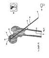
- FIG. 7Ais a sectional view of the osteoendoscopic cylinder of the present invention wherein an endoscope is shown having been inserted there through and into the femoral head so as to facilitate debridement of the femoral head under direct visualization.
- FIG. 7Bis an enhanced sectional view of the femoral head wherein a grasper is shown extending from the endoscope and into the femoral head.
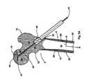
- FIG. 8is an enhanced view of the osteoendoscopic cylinder of the present invention wherein the orientation mark is shown in larger view.
- FIG. 9is a sectional anteroposterior view of the proximal femur after having replaced the segment of osteonecrotic bone of FIG. 4A with bone graft.
- the autogenous cancellous osteomedullary bone cylinderis further shown having been advanced proximally to a second position juxtainferior to the bone graft.
- a friction bony interfaceis shown circumferential to the autogenous cancellous osteomedullary bone cylinder.
- FIG. 10Ais a sectional anteroposterior view of the proximal femur after having advanced further the osteomedullary bone cylinder to a third position juxainferior to a region of overlying cartilage so as to provide mechanical support thereto within the osteocentral canal.
- FIG. 10Bis a sectional view of the proximal femur as in FIG. 7A having the centralized sleeve, the plunger pin, and the osteomedullary cylinder removed therefrom.
- FIG. 10Cis a sectional view of the proximal femur showing the completed procedure.
- FIG. 1There shown generally at 2 in FIG. 1 is an anteroposterior view of a proximal femur having a fernoral head 4 and a femoral neck 6 in anatomic confluency with a greater trochanter 10 and a lesser trochanter 20 .
- Cancellous bone 22is substantially confluent throughout the femoral head 4 , the femoral neck 6 and the greater trochanter 10 .
- the femoral head 4is situated proximally while the greater and lessor trochanters are situated distally.
- the femoral neck 6establishes a cancellous bony pathway 32 therebetween the femoral head proximally and the greater and lesser trochanters distally.
- the greater trochanter 10 and the lesser trochanter 20are in anatomic confluency with a femoral shaft 26 having an outer radius R.
- the fernoral shaft 26is comprised of cortical bone 28 circumferential to a medullary canal 30 having an inner radius r and a neutral axis N.
- the femoral shaft 26includes a medial cortex 12 and a lateral cortex 8 .
- Mis bending moment and is defined as the perpendicular distance from a line of force to a point of interest
- yis the linear distance from the neutral axis
- Iis the areal moment of inertia.
- Equation 2shows that the areal moment of inertia I is inversely proportional to the magnitude of compressive or tensile stresses within the femoral shaft 26 .
- tis the thickness of the cylindrical wall.
- the femoral head 4the femoral neck 6 , and the greater and lesser trochanters 10 and 20 , respectively, are shown in anatomic confluency with the femoral shaft 26 .
- the femoral shaft 26 having the medullary canal 30includes a posterior cortex 14 and an anterior cortex 16 .
- a segment of osteonecrotic bone 18is shown in both views of the proximal femur and is situated in the anterolateral portion of the femoral head 4 .
- FIG. 2the proximal femur of FIG. 1 is shown in two orthogonal views, anteroposterior and lateral, having a plunger pin 34 of the present invention positioned substantially centrally within the segment of osteonecrotic bone 18 .
- the plunger pin 34is advanced proximally into the femoral head with use of a drill 36 and fluoroscopy 38 and first passes through the lateral cortex 8 and the cancellous bony pathway 32 of the femoral neck 6 .
- the plunger pin 34includes a sharpened distal end 40 , a proximal end 42 , and a longitudinal surface 44 having a friction capture region 46 distally situated thereabout the plunger pin.
- the distal end of the plunger pinis advanced into the femoral head 4 .
- a reamer 48is passed over the plunger pin to establish a lateral portal of entry 50 leaving the cancellous bony pathway 32 undisturbed as shown in FIG. 3B .
- a centralizing sleeve 52is shown within the lateral portal of entry 50 having the cancellous bony pathway 32 antecedent thereto the segment of osteonecrotic bone 18 .
- An ostomeclullary cylinder 74 of the present inventionis passed through the centralizing sleeve and advanced proximally into the femoral neck 6 and femoral head 4 axially, concentrically, and centrally about the plunger pin 34 .
- the osteomedullary cylinderremains physically separate from the plunger at all times.
- the osteomedullary cylinder 74passes through the cancellous bony pathway 32 to a first position 54 juxtainferior to the segment of osteonerotic bone 18 .
- the osteomedullary cylinder 74includes a distal bony end 56 and a proximal mechanical end 58 for mounting a handle 60 or the drill 36 .
- the osteomedullary cylinder 74further includes a first low friction inner surface 62 and a second low friction outer surface 66 in coaxial alignment so as to establish a material width 68 therebetween the inner and outer surfaces 62 and 66 , respectively, of the osteomedullary cylinder.
- the material width 68is of a dimension so as to establish a friction bony interface 80 there within the femoral neck 6 .
- An autogenous cancellous osteomedullary bone cylinder 70is uniformly porous having a length of at least 1 cm and an outer radius C and an osteoaxial canal 72 having an inner radius c from a neutral axius n is shown contained there within the osteomedullary cylinder 74 .
- the plunger pin 34is removed from the autogenous cancellous osteomedullary bone cylinder 70 by advancing the plunger pin proximally thereabout the proximal mechanical end 58 .
- proximal mechanical end 58 of the osteomedullary cylinder 74is a proximal retaining support 92 of a size and shape adapted to prevent the removal of the autogenous cancellous osteomedullary bone cylinder 70 from the osteomedullary cylinder in a proximal direction.
- the proximal retaining support 92being circumferentially situated thereabout the proximal mechanical end 58 is further of a size and dimension adapted to allow a displacement plunger 82 to pass there through in a distal direction and into the osteomedullary cylinder 74 .
- the autogenous cancellous osteomedullary bone cylinder 70is only advanced into a proximal portion of the femoral head 4 and the femoral neck 6 by removal of the autogenous cancellous osteomedullary bone cylinder 70 from the osteomedullary cylinder 74 in a distal direction through the distal bony end 56 .
- the geometric configuration thereofis of a construct to resist bending loads during normal gait as in Equation 2 above wherein the areal moment of inertia I bone is inversely proportional to the magnitude of compressive or tensile stresses. More importantly, Equation 2 does not reflect the material properties of bone as does Young's Modulus. Young's modulus of elasticity for cancellous bone may vary from approximately 10 MPa to 2,000 MPa, whereas that for cortical bone is approximately 17,000 MPa.
- the osteoaxial canal 72substantially functions to decompress the femoral head 4 of increased intraosseous hydrostatic pressure characteristic of osteonecrosis of the femoral head.
- FIG. 5is a sectional view of the proximal femur having an osteocentral canal 100 .
- the segment of osteonecrotic bone 18is in structural confluency with the osteocentral canal having a longitudinal canal surface 102 .
- the osteoendoscopic cylinder 94includes an outer bony contact surface 96 of a dimension adapted to contact the longitudinal canal surface 102 so as to tamponade bleeding therefrom, and an inner visual surface 106 .
- the outer bony contact surface 96is further of a size and dimension adapted to establish a hermetic seal at the juncture thereof and the longitudinal canal surface.
- a hermetic sealis also desirable at the juncture of the centralizing sleeve 52 and an inner bony surface 124 of the lateral portal of entry 50 , and yet another hermetic seal at the juncture of the outer bony contact surface 96 and an inner centralizing surface 122 of the centralizing sleeve 52 .
- the osteoendoscopic cylinderis of a size and dimension adapted to receive an endoscope coaxially along the inner visual surface and further includes a proximal handle end 98 and is shown having been engaged by the handle 60 .
- a distal endoscopic end 104is shown in proximity to the segment of osteonecrotic bone 18 .
- the vacuum apparatusinduces a low pressure environment within the femoral head 4 .
- the vacuum apparatusinduces a low pressure environment within the femoral head so as to decompress an elevated intraosseous pressure therein.
- the vacuum apparatusinduces blood to flow from the cancellous bone then visualized within the femoral head with the endoscope thereby allowing the determination of the viability of the segment of osteonecrotic bone 18 .
- FIG. 7Ais a sectional view of the osteoendoscopic cylinder 94 within, the femoral head wherein the distal endoscopic end 104 is situated juxtainferior to the segment of osteonecrotic bone 18 .
- An endoscope 110 having a longitudinal material surface 118is shown having been advanced into the osteoendoscopic cylinder substantially coaxially along the inner visual surface 106 as to create a bony particle chamber 120 for collecting the quantity of osteonecrotic bone fragments 108 debrided from the femoral head.
- the endoscopepasses into the osteoendoscopic cylinder after first passing through the handle 60 and over a proximal stabilizing support 114 .
- the proximal stabilizing supportis of a size and dimension adapted to allow distal and proximal advancement of the endoscope within the osteoendoscopic cylinder at all times thereby allowing visualization of the segment of osteonecrotic hone and the juncture thereof and surrounding cancellous bone.
- the proximal stabilizing supportis further of a size and dimension adapted to prevent the flow of air at the juncture thereof and the longitudinal material surface 118 of the endoscope 110 .
- the surgeonmay manipulate the optics thereof so as to visually observe the osteonecrotic bone and the cancellous bone within the femoral head.
- FIG. 7Bis an enhanced sectional view of the proximal femur wherein a grasping instrument 126 , a reamer, or a probe may be passed through the endoscope and into the femoral head as shown and in so doing, the femoral head may be debrided under direct visualization.
- FIG. 8situated thereabout the distal endoscopic end 104 and along the inner visual surface 106 is an orientation mark 116 .
- the orientation mark 116is of a size and shape adapted to ensure a first visualization thereof with the endoscope 110 .
- the orientation markis in orthogonal alignment with the side opening 112 so as to ensure operational and spatial orientation with respect to the superior, inferor, anterior and posterior bony quadrants within the femoral head at all times.
- the surgeonmay position the side opening 112 in a posterior direction and thereby position the orientation mark 116 anteriorly within the anterior bony quadrant of the femoral head.
- debridement of the femoral headis strategic in that the quality and the location of the osteonecrotic bone then debrided under direct endoscopic visualization can be fully described.
- FIG. 9There shown in FIG. 9 is the osteocavity 76 of the femoral head 4 having been packed with a quantity of morselized cortical or cancellous bone graft 78 .
- FIG. 9further shows the autogenous cancellous osteomedullary hone cylinder having been returned to a second position 86 juxtainferior to the now filled osteocavity 76 .
- the osteoaxial canal 72is in view.
- FIG. 10Ashows the displacement plunger 82 having been passed through the ostcomedullary cylinder 74 to further advance the autogenous cancellous osteomedullary cylinder distally into a proximal portion of the femoral head 4 to a third position 88 juxtainferior to the region of overlying cartilage 64 so as to provide mechanical support thereto.
- the autogenous cancellous osteomedullary hone cylinderis of a length and dimension to provide mechanical support to the region of overlying cartilage and simultaneously remains in contact with the longitudinal canal surface 102 of the osteocentral canal 100 .
- a stabilizing wire 84is shown transfixing the autogenous cancellous osteomedullary bone cylinder so as to ensure the autogenous cancellous osteomedullary bone cylinder remains in the third position 88 .
- a friction bony interface or a stable cylindrical fracture 80is shown circumferentially situated to the autogenous cancellous osteomedullary bone cylinder 70 and is established therebetween a longitudinal bony friction surface 90 of the autogenous cancellous osteomedullary bone cylinder 70 and the longitudinal canal surface 102 of the osteocentral canal 100 .
- FIG. 10Bis a sagittal plane cross sectional view of the femoral neck 6 having the autogenous cancellous osteomedullary bone cylinder 70 centrally positioned therein.
- FIG. 10Cshows the completed procedure wherein the osteomedullary cylinder 74 , the displacement plunger 82 , and the centralizing sleeve 52 have been removed.
Landscapes
- Health & Medical Sciences (AREA)
- Life Sciences & Earth Sciences (AREA)
- Surgery (AREA)
- Orthopedic Medicine & Surgery (AREA)
- General Health & Medical Sciences (AREA)
- Molecular Biology (AREA)
- Veterinary Medicine (AREA)
- Public Health (AREA)
- Nuclear Medicine, Radiotherapy & Molecular Imaging (AREA)
- Engineering & Computer Science (AREA)
- Biomedical Technology (AREA)
- Heart & Thoracic Surgery (AREA)
- Medical Informatics (AREA)
- Animal Behavior & Ethology (AREA)
- Optics & Photonics (AREA)
- Physics & Mathematics (AREA)
- Radiology & Medical Imaging (AREA)
- Pathology (AREA)
- Neurology (AREA)
- Biophysics (AREA)
- Prostheses (AREA)
Abstract
Description
v=−(deltad/do)/(delta 1/10) (1).
σ=My/I (2).
I=¼π(R4−r4), (3).
It=¼πr3t, (4).
Ibone=¼π(C4−c4), (5).
- 2 proximal femur
- 4 a femoral head
- 6 a femoral neck
- 8 a lateral cortex
- 10 a greater trochanter
- 12 a medial cortex
- 14 a posterior cortex
- 16 an anterior cortex
- 18 a segment of osteonecrotic bone
- 20 a lesser trochanter
- 22 cancellous hone
- 24 a compaction sleeve
- 26 a femoral shaft
- 28 cortical bone
- 30 a medullary canal
- 32 a cancellous bony pathway
- 34 a plunger pin
- 36 a drill
- 38 fluoroscopy
- 40 a sharpened distal end
- 42 a proximal end
- 44 a longitudinal surface
- 46 a friction capture region.
- 48 a reamer
- 50 a lateral portal of entry
- 52 a centralizing sleeve
- 54 a first position
- 56 a distal bony end
- 58 a proximal mechanical end
- 60 a handle
- 62 a first low friction inner surface
- 64 a region of overlying cartilage
- 66 a second low friction outer surface
- 68 a material width
- 70 an autogenous cancellous osteomedullary hone cylinder
- 72 an osteoaxial canal
- 74 an osteomedullary cylinder
- 76 a partially debrided osteocavity
- 78 morselized cortical or cancellous bone
- 80 a friction bony interface
- 82 a displacement plunger
- 84 a stabilizing wire
- 86 a second position
- 88 a third position
- 90 a longitudinal bony friction surface
- 92 a proximal retaining support
- 94 an osteoendoscopic cylinder
- 96 an outer bony contact surface
- 98 a proximal handle end
- 100 an osteocentral canal
- 102 a longitudinal canal surface
- 104 a distal endoscopic end
- 106 an inner visual surface
- 108 a quantity of osteonecrotic bone fragments
- 110 an endoscope
- 112 a side opening
- 114 a proximal stabilizing support
- 116 a plurality of orientation marks
- 118 a longitudinal material surface
- 120 a bony particle chamber
- 122 an inner centralizing surface
- 124 an inner bony surface
- 126 a grasping instrument
- 128 a vacuum apparatus
Claims (5)
Priority Applications (1)
| Application Number | Priority Date | Filing Date | Title |
|---|---|---|---|
| US12/181,205US8382762B2 (en) | 2001-09-19 | 2008-07-28 | Endoscopic bone debridement |
Applications Claiming Priority (3)
| Application Number | Priority Date | Filing Date | Title |
|---|---|---|---|
| US09/957,817US20030055316A1 (en) | 2001-09-19 | 2001-09-19 | Endoscopic bone debridement |
| US10/928,553US7445595B2 (en) | 2001-09-19 | 2004-08-26 | Endoscopic bone debridement |
| US12/181,205US8382762B2 (en) | 2001-09-19 | 2008-07-28 | Endoscopic bone debridement |
Related Parent Applications (1)
| Application Number | Title | Priority Date | Filing Date |
|---|---|---|---|
| US10/928,553DivisionUS7445595B2 (en) | 2001-09-19 | 2004-08-26 | Endoscopic bone debridement |
Publications (2)
| Publication Number | Publication Date |
|---|---|
| US20080288006A1 US20080288006A1 (en) | 2008-11-20 |
| US8382762B2true US8382762B2 (en) | 2013-02-26 |
Family
ID=25500183
Family Applications (3)
| Application Number | Title | Priority Date | Filing Date |
|---|---|---|---|
| US09/957,817AbandonedUS20030055316A1 (en) | 2001-09-19 | 2001-09-19 | Endoscopic bone debridement |
| US10/928,553Expired - LifetimeUS7445595B2 (en) | 2001-09-19 | 2004-08-26 | Endoscopic bone debridement |
| US12/181,205Expired - Fee RelatedUS8382762B2 (en) | 2001-09-19 | 2008-07-28 | Endoscopic bone debridement |
Family Applications Before (2)
| Application Number | Title | Priority Date | Filing Date |
|---|---|---|---|
| US09/957,817AbandonedUS20030055316A1 (en) | 2001-09-19 | 2001-09-19 | Endoscopic bone debridement |
| US10/928,553Expired - LifetimeUS7445595B2 (en) | 2001-09-19 | 2004-08-26 | Endoscopic bone debridement |
Country Status (1)
| Country | Link |
|---|---|
| US (3) | US20030055316A1 (en) |
Cited By (3)
| Publication number | Priority date | Publication date | Assignee | Title |
|---|---|---|---|---|
| US20140074103A1 (en)* | 2012-09-07 | 2014-03-13 | Zimmer Gmbh, Inc. | Subchondral treatment of bone defects with bone-derived implant |
| US11523834B1 (en) | 2022-06-20 | 2022-12-13 | University Of Utah Research Foundation | Cartilage and bone harvest and delivery system and methods |
| US11660194B1 (en) | 2022-06-20 | 2023-05-30 | University Of Utah Research Foundation | Cartilage and bone harvest and delivery system and methods |
Families Citing this family (35)
| Publication number | Priority date | Publication date | Assignee | Title |
|---|---|---|---|---|
| US20030055316A1 (en)* | 2001-09-19 | 2003-03-20 | Brannon James Kevin | Endoscopic bone debridement |
| FR2903004B1 (en)* | 2006-07-03 | 2009-07-10 | Oreal | COSMETIC USE OF A C-GLYCOSIDE DERIVATIVE IN ASSOCIATION WITH ASCORBIC ACID |
| ES2279733B1 (en)* | 2006-11-27 | 2008-08-16 | Rudolf Morgenstern Lopez | DEVICE FOR ELIMINATION OF FABRIC IN ENDOSCOPIC OPERATIONS. |
| US8062364B1 (en) | 2007-04-27 | 2011-11-22 | Knee Creations, Llc | Osteoarthritis treatment and device |
| EP2152141B1 (en)* | 2007-05-03 | 2014-07-30 | Mediola Kft. | Device for measuring blood flow in the bone after a fracture |
| US7780740B2 (en)* | 2007-05-21 | 2010-08-24 | Active Implants Corporation | Methods, systems, and apparatus for implanting prosthetic devices into cartilage |
| US8343157B2 (en) | 2007-05-25 | 2013-01-01 | Howmedica Osteonics Corp. | Bone-reaming system |
| EP2303155A4 (en)* | 2008-06-23 | 2014-08-27 | Allosource | ASEPTIC CLEANING ROOM WITH HIGH PRESSURE WATER |
| US7836967B2 (en)* | 2008-07-28 | 2010-11-23 | Caterpillar Inc | Cooling system packaging arrangement for a machine |
| US8303594B2 (en)* | 2008-12-30 | 2012-11-06 | Howmedica Osteonics Corp. | Method and apparatus for removal of tissue |
| US8864768B2 (en) | 2009-11-20 | 2014-10-21 | Zimmer Knee Creations, Inc. | Coordinate mapping system for joint treatment |
| US8951261B2 (en) | 2009-11-20 | 2015-02-10 | Zimmer Knee Creations, Inc. | Subchondral treatment of joint pain |
| JP2013511356A (en) | 2009-11-20 | 2013-04-04 | ニー・クリエイションズ・リミテッド・ライアビリティ・カンパニー | Device for variable angle approach to joints |
| US9259257B2 (en) | 2009-11-20 | 2016-02-16 | Zimmer Knee Creations, Inc. | Instruments for targeting a joint defect |
| WO2011063260A1 (en) | 2009-11-20 | 2011-05-26 | Knee Creations, Llc | Bone-derived implantable devices for subchondral treatment of joint pain |
| EP2501303B1 (en) | 2009-11-20 | 2020-02-12 | Zimmer Knee Creations, Inc. | Navigation and positioning instruments for joint repair |
| WO2011063240A1 (en) | 2009-11-20 | 2011-05-26 | Knee Creations, Llc | Implantable devices for subchondral treatment of joint pain |
| US8821504B2 (en) | 2009-11-20 | 2014-09-02 | Zimmer Knee Creations, Inc. | Method for treating joint pain and associated instruments |
| KR101075847B1 (en)* | 2009-12-21 | 2011-10-25 | 가톨릭대학교 산학협력단 | Surgical equipment for avascular necrosis of femoral head |
| US8740114B2 (en) | 2010-01-07 | 2014-06-03 | Metronic Xomed, Inc. | System and method of bone processing |
| GB201001573D0 (en) | 2010-02-01 | 2010-03-17 | Univ Antwerpen | Method and device for endoscopically assisted arthroplasty |
| JP5327986B2 (en)* | 2011-03-31 | 2013-10-30 | 富士フイルム株式会社 | Endoscope insertion aid |
| US8529574B2 (en) | 2011-06-22 | 2013-09-10 | Howmedica Osteonics Corp. | Cutting guide for removal of cam lesion |
| US20160199072A1 (en)* | 2013-08-19 | 2016-07-14 | Smith & Nephew, Inc. | Bone removal under direct visualization |
| EP3148451B1 (en)* | 2014-07-30 | 2018-06-06 | Medovex Corp. | Surgical tools for spinal facet therapy to alleviate pain |
| CN104352273B (en)* | 2014-10-14 | 2018-04-27 | 中南大学湘雅三医院 | Prevent After femoral neck fracture caput femoris necrosis and treat the device of caput femoris necrosis |
| US11666447B1 (en)* | 2015-03-05 | 2023-06-06 | Taq Ortho, LLC | Bone implant augment and offset device |
| US10610242B2 (en) | 2015-05-08 | 2020-04-07 | Fortus Medical, Inc. | Bone fragment and tissue harvesting system |
| AU2017204355B2 (en) | 2016-07-08 | 2021-09-09 | Mako Surgical Corp. | Scaffold for alloprosthetic composite implant |
| CN106264701A (en)* | 2016-08-05 | 2017-01-04 | 王成斌 | Fracture of femoral neck bone grafting instrument |
| EP3509520B1 (en) | 2016-09-07 | 2021-07-28 | Fortus Medical, Inc. | Bone void filler preparation system |
| WO2018226562A1 (en) | 2017-06-07 | 2018-12-13 | Fortus Medical, Inc. | Connective tissue progenitor cell aspiration and processing system |
| US11278336B2 (en)* | 2018-03-22 | 2022-03-22 | Fortus Medical, Inc. | Osteomedullary tissue processing system |
| CN113331931B (en)* | 2021-05-25 | 2022-05-17 | 长沙年轮骨科医院有限公司 | Fracture intramedullary fixation device and method |
| CN113730049B (en)* | 2021-09-18 | 2023-07-18 | 河南省中医院(河南中医药大学第二附属医院) | A compression bone graft support device for femoral head necrosis |
Citations (170)
| Publication number | Priority date | Publication date | Assignee | Title |
|---|---|---|---|---|
| US2121193A (en)* | 1932-12-21 | 1938-06-21 | Hanicke Paul Gustav Erich | Fracture clamping apparatus |
| US2381050A (en)* | 1943-12-04 | 1945-08-07 | Mervyn G Hardinge | Fracture reducing device |
| US2397545A (en)* | 1945-02-13 | 1946-04-02 | Mervyn G Hardinge | Self-adjusting fracture reducing device |
| US2536964A (en)* | 1949-05-26 | 1951-01-02 | Guidoscope Corp | Surgical or fracture nail |
| US2537070A (en)* | 1948-12-27 | 1951-01-09 | Puy Mfg Company Inc De | Surgical appliance and method for fixation of bone fragments |
| US2570465A (en)* | 1949-08-01 | 1951-10-09 | Joseph S Lundholm | Means for fixation of hip fractures |
| US2612159A (en)* | 1949-03-01 | 1952-09-30 | Marie B Collison | Trochanteric plate for bone surgery |
| US2621653A (en)* | 1949-04-29 | 1952-12-16 | Briggs Henry | Fracture reducing device |
| US2682265A (en)* | 1951-12-28 | 1954-06-29 | Marie B Collison | Trochanteric plate and artificial femoral head |
| US2699774A (en)* | 1952-05-12 | 1955-01-18 | Livingston Herman Harrison | Bone pin locking device |
| US2772676A (en)* | 1951-12-06 | 1956-12-04 | Pohl Ernst | Connecting device for bone fractures in the neighborhood of joints |
| US2801631A (en)* | 1954-08-18 | 1957-08-06 | Charnley John | Fracture screw adjusting means |
| US3051169A (en)* | 1957-12-07 | 1962-08-28 | Stille Werner Ab | Surgical screw connector |
| US3716051A (en)* | 1970-09-10 | 1973-02-13 | Fischer Artur | Expandible connector for fractured bones |
| US3822697A (en) | 1973-03-20 | 1974-07-09 | Olympus Optical Co | Envelope of an endoscope |
| US3996931A (en)* | 1975-07-03 | 1976-12-14 | Callender Jr George R | Fractured bone setting fastener assembly |
| US4432358A (en)* | 1982-01-22 | 1984-02-21 | Fixel Irving E | Compression hip screw apparatus |
| US4438762A (en)* | 1981-12-30 | 1984-03-27 | Richard F. Kyle | Orthopedic hip fixation device |
| US4449532A (en) | 1980-07-08 | 1984-05-22 | Karl Storz | Dilator to facilitate endoscope insertion into the body |
| US4621629A (en)* | 1985-08-12 | 1986-11-11 | Harrington Arthritis Research Center | Compression hip screw |
| US4628923A (en)* | 1983-11-28 | 1986-12-16 | Medoff Robert J | Axial compression device |
| US4653489A (en)* | 1984-04-02 | 1987-03-31 | Tronzo Raymond G | Fenestrated hip screw and method of augmented fixation |
| US4696308A (en)* | 1986-04-09 | 1987-09-29 | The Cleveland Clinic Foundation | Core sampling apparatus |
| US4760844A (en)* | 1986-03-21 | 1988-08-02 | Ace Medical Company | Cannulated screw dye injector |
| US4765314A (en) | 1985-01-09 | 1988-08-23 | Aesculap-Werke Aktiengesellschaft | Device for introducing an endoscope or a surgical tool into body cavities with a feed for a flushing medium and an extractor for said flushing medium |
| US4776329A (en)* | 1985-09-20 | 1988-10-11 | Richards Medical Company | Resorbable compressing screw and method |
| US4823780A (en)* | 1984-03-14 | 1989-04-25 | Odensten Magnus G | Drill guiding and aligning device |
| US4863444A (en)* | 1985-09-19 | 1989-09-05 | Bloemer Alois | Antibiotic-containing agent and its use as a surgical plastic material |
| US4911153A (en)* | 1988-02-04 | 1990-03-27 | Biomet, Inc. | Orthopedic surgical instrument |
| USRE33348E (en)* | 1985-11-07 | 1990-09-25 | Zimmer, Inc. | Bone screw |
| US4959064A (en)* | 1988-10-07 | 1990-09-25 | Boehringer Mannheim Corporation | Dynamic tension bone screw |
| US4973332A (en)* | 1988-09-12 | 1990-11-27 | Hospital For Joint Diseases | Attachment for femur sliding screw plate |
| US5007910A (en)* | 1989-01-04 | 1991-04-16 | Emmanuel Anapliotis | Device for compression screwing |
| US5041116A (en)* | 1990-05-21 | 1991-08-20 | Wilson James T | Compression hip screw system |
| US5102413A (en)* | 1990-11-14 | 1992-04-07 | Poddar Satish B | Inflatable bone fixation device |
| US5108404A (en)* | 1989-02-09 | 1992-04-28 | Arie Scholten | Surgical protocol for fixation of bone using inflatable device |
| US5287845A (en) | 1991-01-19 | 1994-02-22 | Olympus Winter & Ibe Gmbh | Endoscope for transurethral surgery |
| US5324295A (en)* | 1992-04-24 | 1994-06-28 | Shapiro Michael R | Drill guide for surgical pins |
| US5400767A (en) | 1991-05-14 | 1995-03-28 | Murdoch; Mervyn J. | Laparoscopic telescope lens cleaner and protector |
| US5413578A (en) | 1989-03-14 | 1995-05-09 | Zahedi; Amir | Device for removing a bone cement tube |
| US5441503A (en)* | 1988-09-24 | 1995-08-15 | Considine; John | Apparatus for removing tumors from hollow organs of the body |
| US5464008A (en)* | 1994-04-14 | 1995-11-07 | Kim; John H. | Laparoscope defogging |
| US5514138A (en)* | 1991-02-08 | 1996-05-07 | Pfizer Inc. | Connector having a stop member |
| US5575756A (en)* | 1993-08-16 | 1996-11-19 | Olympus Optical Co., Ltd. | Endoscope apparatus |
| US5578035A (en)* | 1995-05-16 | 1996-11-26 | Lin; Chih-I | Expandable bone marrow cavity fixation device |
| US5591168A (en)* | 1993-10-25 | 1997-01-07 | Tornier S.A. | Device for stabilizing fractures of the upper end of the femur |
| US5681262A (en)* | 1994-10-05 | 1997-10-28 | Very Inventive Physicians Inc. | Endoscope and tool therefore |
| US5743912A (en)* | 1995-08-23 | 1998-04-28 | Biomat | Upper femoral epiphysis osteosynthesis implant |
| US5755809A (en)* | 1995-06-07 | 1998-05-26 | Implex Corporation | Femoral head core channel filling prothesis |
| US5755797A (en)* | 1993-04-21 | 1998-05-26 | Sulzer Medizinaltechnik Ag | Intervertebral prosthesis and a process for implanting such a prosthesis |
| US5759184A (en)* | 1993-07-23 | 1998-06-02 | Santangelo; Massimo | Device for preventive support of the femur |
| US5800553A (en)* | 1991-07-23 | 1998-09-01 | Aktiebolaget Astra | Hip joint prosthesis to be permanently anchored within a femur of a patient |
| US5800439A (en)* | 1997-05-16 | 1998-09-01 | Clyburn; Terry A. | Cement injection and intramedullary canal drying system |
| US5810821A (en)* | 1997-03-28 | 1998-09-22 | Biomet Inc. | Bone fixation screw system |
| US5824087A (en)* | 1994-04-11 | 1998-10-20 | Aberdeen University And Plasma Biotal Limited | Bone regeneration |
| US5827312A (en)* | 1995-06-09 | 1998-10-27 | Instratek Incorporated | Marked cannula |
| US5849023A (en)* | 1996-12-27 | 1998-12-15 | Mericle; Robert William | Disposable remote flexible drive cutting apparatus |
| USRE36020E (en)* | 1992-06-08 | 1998-12-29 | Orthopedic Systems, Inc. | Method and apparatus for tying suture to bone |
| US5878886A (en)* | 1996-09-20 | 1999-03-09 | Marshall; John C. | Display package for pull chains and the like |
| US5899908A (en)* | 1993-02-10 | 1999-05-04 | Sulzer Spine-Tech Inc. | Spinal drill tube guide |
| US5913867A (en)* | 1996-12-23 | 1999-06-22 | Smith & Nephew, Inc. | Surgical instrument |
| US5919196A (en)* | 1995-02-16 | 1999-07-06 | Arthrex, Inc. | Method and apparatus for osteochondral autograft transplantation |
| US5968050A (en)* | 1997-12-05 | 1999-10-19 | Smith & Nephew, Inc. | Positioning a tibial tunnel |
| US5972015A (en)* | 1997-08-15 | 1999-10-26 | Kyphon Inc. | Expandable, asymetric structures for deployment in interior body regions |
| US5976139A (en)* | 1996-07-17 | 1999-11-02 | Bramlet; Dale G. | Surgical fastener assembly |
| US5980525A (en)* | 1997-10-27 | 1999-11-09 | Bristol-Myers Squibb Company | Bone reamer with impeller |
| US5997582A (en)* | 1998-05-01 | 1999-12-07 | Weiss; James M. | Hip replacement methods and apparatus |
| US6001106A (en)* | 1997-09-03 | 1999-12-14 | M & R Medical, Inc. | System for tensioning ligament grafts |
| US6017348A (en)* | 1995-03-07 | 2000-01-25 | Innovasive Devices, Inc. | Apparatus and methods for articular cartilage defect repair |
| US6019767A (en)* | 1990-07-16 | 2000-02-01 | Arthrotek | Tibial guide |
| US6071284A (en)* | 1995-10-30 | 2000-06-06 | Biomedical Enterprises, Inc. | Materials collection system and uses thereof |
| US6086530A (en) | 1998-10-30 | 2000-07-11 | Mack; Michael | Adjustable sleeve for endoscopes |
| US6120511A (en)* | 1997-11-18 | 2000-09-19 | Chan; Kwan-Ho | Drill guide assembly and method for producing a bone tunnel |
| US6132433A (en)* | 1997-02-12 | 2000-10-17 | Arthrex, Inc. | Apparatus of loading tendons into the knee |
| US6139552A (en)* | 1998-05-13 | 2000-10-31 | K. K. Hollyx | Bone jointer and a bone jointer fixing tool |
| US6142931A (en) | 1997-10-06 | 2000-11-07 | Olympus Optical Co., Ltd. | Guide tube unit for endoscope and method for resecting a tissue |
| US6217619B1 (en)* | 1997-12-05 | 2001-04-17 | GMT GESELLSCHAFT FüR MEDIZINISCHE TECHNIK MBH | Endoprosthesis for a least partial replacement of a tibia |
| US6235043B1 (en)* | 1994-01-26 | 2001-05-22 | Kyphon, Inc. | Inflatable device for use in surgical protocol relating to fixation of bone |
| US6248110B1 (en)* | 1994-01-26 | 2001-06-19 | Kyphon, Inc. | Systems and methods for treating fractured or diseased bone using expandable bodies |
| US6270502B1 (en)* | 1998-12-11 | 2001-08-07 | Smith & Nephew, Inc. | Methods and instruments for performing radial impacting |
| US6280474B1 (en)* | 1997-01-09 | 2001-08-28 | Neucoll, Inc. | Devices for tissue repair and methods for preparation and use thereof |
| US6299648B1 (en)* | 2000-03-17 | 2001-10-09 | Hammill Manufacturing Co. | Locking hip prosthesis |
| US6315714B1 (en)* | 1998-11-30 | 2001-11-13 | Fuji Photo Optical Co., Ltd. | Endoscope insertion guide pipe |
| US6354992B1 (en) | 1999-11-08 | 2002-03-12 | Daniel T. Kato | Automated laparoscopic lens cleaner |
| US6358251B1 (en)* | 2000-03-21 | 2002-03-19 | University Of Washington | Method and apparatus for forming a cavity in soft tissue or bone |
| US20020068974A1 (en)* | 2000-07-21 | 2002-06-06 | Kuslich Stephen D. | Expandable porous mesh bag device and methods of use for reduction, filling, fixation and supporting of bone |
| US20020077701A1 (en)* | 2000-12-15 | 2002-06-20 | Kuslich Stephen D. | Annulus-reinforcing band |
| US6440061B1 (en) | 2000-03-24 | 2002-08-27 | Donald E. Wenner | Laparoscopic instrument system for real-time biliary exploration and stone removal |
| US6520907B1 (en)* | 1996-03-22 | 2003-02-18 | Sdgi Holdings, Inc. | Methods for accessing the spinal column |
| US6537274B1 (en)* | 2000-09-28 | 2003-03-25 | Biomet, Inc. | Fixation screw, detachable pin, guide, and frame |
| US20030083662A1 (en)* | 2001-11-01 | 2003-05-01 | Middleton Lance M. | Orthopaedic implant fixation using an in-situ formed anchor |
| US20030097132A1 (en)* | 2001-11-19 | 2003-05-22 | Marty Padget | Proximal anchors for bone fixation system |
| US20030120278A1 (en)* | 2000-05-26 | 2003-06-26 | Morgan Craig D. | Retrograde fixation technique with insert-molded interference screw |
| US20030130741A1 (en)* | 2002-01-07 | 2003-07-10 | Mcminn Derek James Wallace | Hip prosthesis |
| US20030135214A1 (en)* | 2002-01-15 | 2003-07-17 | Fetto Joseph F. | System, device, composition and method for treating and preventing avascular or osteonecrosis |
| US6607561B2 (en)* | 2001-10-02 | 2003-08-19 | James Kevin Brannon | Biaxial core compression |
| US6632235B2 (en)* | 2001-04-19 | 2003-10-14 | Synthes (U.S.A.) | Inflatable device and method for reducing fractures in bone and in treating the spine |
| US20040010252A1 (en)* | 2002-03-21 | 2004-01-15 | Stryker Trauma Gmbh | Locking nail and targeting apparatus |
| US6679890B2 (en)* | 2001-08-28 | 2004-01-20 | Joseph Y. Margulies | Method and apparatus for augmentation of the femoral neck |
| US6740093B2 (en)* | 2000-02-28 | 2004-05-25 | Stephen Hochschuler | Method and apparatus for treating a vertebral body |
| US6746451B2 (en)* | 2001-06-01 | 2004-06-08 | Lance M. Middleton | Tissue cavitation device and method |
| US6755865B2 (en)* | 2001-09-24 | 2004-06-29 | Imad Ed. Tarabishy | Joint prosthesis and method for placement |
| US20040162621A1 (en)* | 2002-04-11 | 2004-08-19 | Crofford Theodore W. | Femoral neck fixation prosthesis |
| US20040167532A1 (en)* | 2002-06-26 | 2004-08-26 | Scimed Life Systems, Inc. | Retrograde plunger delivery system |
| US6827720B2 (en)* | 2002-01-15 | 2004-12-07 | Alejandro Leali | System and method for treating osteonecrosis |
| US6827722B1 (en)* | 2001-12-11 | 2004-12-07 | Biomet, Inc. | Method and apparatus for use of a guide wire capturing surgical instrument |
| US20050015148A1 (en)* | 2003-07-18 | 2005-01-20 | Jansen Lex P. | Biocompatible wires and methods of using same to fill bone void |
| US20050043805A1 (en)* | 2003-08-11 | 2005-02-24 | Chudik Steven C. | Devices and methods used for shoulder replacement |
| US6887243B2 (en)* | 2001-03-30 | 2005-05-03 | Triage Medical, Inc. | Method and apparatus for bone fixation with secondary compression |
| US6890333B2 (en)* | 2001-03-30 | 2005-05-10 | Triage Medical, Inc. | Method and apparatus for bone fixation with secondary compression |
| US20050143745A1 (en)* | 2003-12-30 | 2005-06-30 | Medicinelodge, Inc. | Instruments and methods for preparing a joint articulation surface for an implant |
| US20050234464A1 (en)* | 2001-09-19 | 2005-10-20 | Brannon James K | Endoscopic bone debridement |
| US20050278023A1 (en)* | 2004-06-10 | 2005-12-15 | Zwirkoski Paul A | Method and apparatus for filling a cavity |
| US20060052874A1 (en)* | 2004-09-09 | 2006-03-09 | Johnson Wesley M | Prostheses for spine discs having fusion capability |
| US7025771B2 (en)* | 2000-06-30 | 2006-04-11 | Spineology, Inc. | Tool to direct bone replacement material |
| US20060085081A1 (en)* | 2004-06-07 | 2006-04-20 | Shadduck John H | Implants and methods for treating bone |
| US20060085006A1 (en)* | 2002-12-03 | 2006-04-20 | Ek Steven W | System and method for retrograde procedure |
| US20060106461A1 (en)* | 2004-11-12 | 2006-05-18 | Embry Jill M | Implantable vertebral lift |
| US20060149362A1 (en)* | 2004-12-30 | 2006-07-06 | Pedrozo Hugo A | Orthopaedic implant for vascularization of the femoral head |
| US7135023B2 (en)* | 2003-07-07 | 2006-11-14 | Watkins William T | Compression bone screw device |
| US20060265077A1 (en)* | 2005-02-23 | 2006-11-23 | Zwirkoski Paul A | Spinal repair |
| US7160305B2 (en)* | 2003-03-07 | 2007-01-09 | Arthrex, Inc. | Retrodrill technique for insertion of autograft, allograft or synthetic osteochondral implants |
| US20070055274A1 (en)* | 2005-06-20 | 2007-03-08 | Andreas Appenzeller | Apparatus and methods for treating bone |
| US20070088436A1 (en)* | 2005-09-29 | 2007-04-19 | Matthew Parsons | Methods and devices for stenting or tamping a fractured vertebral body |
| US20070093899A1 (en)* | 2005-09-28 | 2007-04-26 | Christof Dutoit | Apparatus and methods for treating bone |
| US20070093822A1 (en)* | 2005-09-28 | 2007-04-26 | Christof Dutoit | Apparatus and methods for vertebral augmentation using linked expandable bodies |
| US20070118136A1 (en)* | 2002-12-03 | 2007-05-24 | Arthrosurface, Inc. | Tibial resurfacing system |
| US20070162132A1 (en)* | 2005-12-23 | 2007-07-12 | Dominique Messerli | Flexible elongated chain implant and method of supporting body tissue with same |
| US20070162044A1 (en)* | 2005-11-23 | 2007-07-12 | Trinity Orthopedics | Percutaneous transpedicular access, fusion, discectomy, and stabilization system and method |
| US20070173939A1 (en)* | 2005-12-23 | 2007-07-26 | The Board Of Trustees Of The Leland Stanford Junior University | Systems and methods for fixation of bone with an expandable device |
| US20070255420A1 (en)* | 2005-08-26 | 2007-11-01 | Johnson James F | Thrust plate hip prosthesis |
| US7303577B1 (en)* | 2003-02-05 | 2007-12-04 | Dean John C | Apparatus and method for use in repairs of injured soft tissue |
| US20070282346A1 (en)* | 1998-08-14 | 2007-12-06 | Kyphon Inc. | Systems and methods for treating vertebral bodies |
| US20080009792A1 (en)* | 2006-01-27 | 2008-01-10 | Bruce Henniges | System and method for deliverying an agglomeration of solid beads and cement to the interior of a bone in order to form an implant within the bone |
| US20080051800A1 (en)* | 2004-05-03 | 2008-02-28 | Robert Diaz | Method and device for reducing susceptibility to fractures in vertebral bodies |
| US20080300603A1 (en)* | 2007-06-04 | 2008-12-04 | Ao Technology Ag | Method for placement of bone cement into pre-selected bone regions |
| US7465318B2 (en)* | 2004-04-15 | 2008-12-16 | Soteira, Inc. | Cement-directing orthopedic implants |
| US20080319444A9 (en)* | 1997-06-09 | 2008-12-25 | Kyphon Inc. | Methods and devices for treating bone after high velocity and/or trauma fracture |
| US20090043344A1 (en)* | 2007-08-06 | 2009-02-12 | Zimmer, Inc. | Methods for repairing defects in bone |
| US20090112221A1 (en)* | 2007-10-25 | 2009-04-30 | Disc Dynamics, Inc. | System and method for measuring the shape of internal body cavities |
| US20090143716A1 (en)* | 2007-11-27 | 2009-06-04 | David Lowry | Methods and systems for repairing an intervertebral disc using a transcorporal approach |
| US20090171361A1 (en)* | 2007-12-27 | 2009-07-02 | Melsheimer Jeffry S | Apparatus and method for mixing and dispensing a bone cement mixture |
| US20090177206A1 (en)* | 2008-01-08 | 2009-07-09 | Zimmer Spine, Inc. | Instruments, implants, and methods for fixation of vertebral compression fractures |
| US20090187249A1 (en)* | 2008-01-23 | 2009-07-23 | Osman Said G | Biologic Vertebral Reconstruction |
| US20090187190A1 (en)* | 2000-08-14 | 2009-07-23 | Spine Wave, Inc. | Transverse Cavity Device and Method |
| US20090204216A1 (en)* | 2007-12-28 | 2009-08-13 | Lutz Biedermann | Implant for stabilizing vertebrae or bones |
| US20090240334A1 (en)* | 2008-03-19 | 2009-09-24 | Richelsoph Marc E | Vertebral device for restoration of vertebral body height |
| US20090264942A1 (en)* | 2003-06-17 | 2009-10-22 | Depuy Spine, Inc. | Methods, Materials and Apparatus for Treating Bone and Other Tissue |
| US20090275995A1 (en)* | 2004-12-06 | 2009-11-05 | Dfine, Inc. | Bone treatment systems and methods |
| US20090281545A1 (en)* | 2008-03-05 | 2009-11-12 | Allston J. Stubbs | Method and Apparatus for Arthroscopic Assisted Arthroplasty of the Hip Joint |
| US7621950B1 (en)* | 1999-01-27 | 2009-11-24 | Kyphon Sarl | Expandable intervertebral spacer |
| US20100174284A1 (en)* | 2008-10-15 | 2010-07-08 | Zimmer, Gmbh | Intramedullary nail |
| US20100211073A1 (en)* | 2009-02-17 | 2010-08-19 | Gregory Merrell | Intramedullary compression rod |
| US20100331841A1 (en)* | 2004-01-16 | 2010-12-30 | Expanding Orthopedics, Inc. | Bone fracture treatment devices and methods of their use |
| US20110015680A1 (en)* | 2002-08-27 | 2011-01-20 | Warsaw Orthopedic, Inc. | Systems and methods for intravertebral reduction |
| US7896885B2 (en)* | 2002-12-03 | 2011-03-01 | Arthrosurface Inc. | Retrograde delivery of resurfacing devices |
| US20110060373A1 (en)* | 2009-09-09 | 2011-03-10 | Russell Thomas A | Bone screws and methods of use thereof |
| US20110060337A1 (en)* | 2003-09-08 | 2011-03-10 | Smith & Nephew, Inc. | Orthopaedic Implant and Fastener Assembly |
| US7914545B2 (en)* | 2002-12-03 | 2011-03-29 | Arthrosurface, Inc | System and method for retrograde procedure |
| US7951163B2 (en)* | 2003-11-20 | 2011-05-31 | Arthrosurface, Inc. | Retrograde excision system and apparatus |
| US20110172667A1 (en)* | 2008-06-26 | 2011-07-14 | AO Tecnology AG | Bone fixation device with cover |
| US20110172668A1 (en)* | 2010-01-13 | 2011-07-14 | Frake Paul C | Intramedullary Mandibular Condyle Implants and Method for Application of the Same |
| US20110218531A1 (en)* | 2010-03-04 | 2011-09-08 | Skeletal Dynamics Llc | Endosteal nail plate for fixing bone segments |
| US20110282346A1 (en)* | 2008-06-10 | 2011-11-17 | Sonoma Orthopedic Products, Inc. | Fracture Fixation Device, Tools and Methods |
| US20110282347A1 (en)* | 2010-05-11 | 2011-11-17 | Gordon J Eric | Pediatric intramedullary nail |
| US20110282395A1 (en)* | 2009-01-16 | 2011-11-17 | Carbofix Orthopedics Ltd. | Composite material bone implant |
| US20110295255A1 (en)* | 2009-02-05 | 2011-12-01 | Sonoma Orthopedic Products, Inc. | Proximal femur fixation apparatus, systems and methods with angled elongate elements |
| US20110295254A1 (en)* | 2008-05-07 | 2011-12-01 | Tornier Sas | Implant locking device and corresponding implant |
| US20110306975A1 (en)* | 2009-08-31 | 2011-12-15 | Ozics Oy | Arrangement for internal bone support |
| US20110313420A1 (en)* | 2010-06-18 | 2011-12-22 | Lecronier David | Easily implantable and stable nail-fastener for skeletal fixation and method |
- 2001
- 2001-09-19USUS09/957,817patent/US20030055316A1/ennot_activeAbandoned
- 2004
- 2004-08-26USUS10/928,553patent/US7445595B2/ennot_activeExpired - Lifetime
- 2008
- 2008-07-28USUS12/181,205patent/US8382762B2/ennot_activeExpired - Fee Related
Patent Citations (178)
| Publication number | Priority date | Publication date | Assignee | Title |
|---|---|---|---|---|
| US2121193A (en)* | 1932-12-21 | 1938-06-21 | Hanicke Paul Gustav Erich | Fracture clamping apparatus |
| US2381050A (en)* | 1943-12-04 | 1945-08-07 | Mervyn G Hardinge | Fracture reducing device |
| US2397545A (en)* | 1945-02-13 | 1946-04-02 | Mervyn G Hardinge | Self-adjusting fracture reducing device |
| US2537070A (en)* | 1948-12-27 | 1951-01-09 | Puy Mfg Company Inc De | Surgical appliance and method for fixation of bone fragments |
| US2612159A (en)* | 1949-03-01 | 1952-09-30 | Marie B Collison | Trochanteric plate for bone surgery |
| US2621653A (en)* | 1949-04-29 | 1952-12-16 | Briggs Henry | Fracture reducing device |
| US2536964A (en)* | 1949-05-26 | 1951-01-02 | Guidoscope Corp | Surgical or fracture nail |
| US2570465A (en)* | 1949-08-01 | 1951-10-09 | Joseph S Lundholm | Means for fixation of hip fractures |
| US2772676A (en)* | 1951-12-06 | 1956-12-04 | Pohl Ernst | Connecting device for bone fractures in the neighborhood of joints |
| US2682265A (en)* | 1951-12-28 | 1954-06-29 | Marie B Collison | Trochanteric plate and artificial femoral head |
| US2699774A (en)* | 1952-05-12 | 1955-01-18 | Livingston Herman Harrison | Bone pin locking device |
| US2801631A (en)* | 1954-08-18 | 1957-08-06 | Charnley John | Fracture screw adjusting means |
| US3051169A (en)* | 1957-12-07 | 1962-08-28 | Stille Werner Ab | Surgical screw connector |
| US3716051A (en)* | 1970-09-10 | 1973-02-13 | Fischer Artur | Expandible connector for fractured bones |
| US3822697A (en) | 1973-03-20 | 1974-07-09 | Olympus Optical Co | Envelope of an endoscope |
| US3996931A (en)* | 1975-07-03 | 1976-12-14 | Callender Jr George R | Fractured bone setting fastener assembly |
| US4449532A (en) | 1980-07-08 | 1984-05-22 | Karl Storz | Dilator to facilitate endoscope insertion into the body |
| US4438762A (en)* | 1981-12-30 | 1984-03-27 | Richard F. Kyle | Orthopedic hip fixation device |
| US4432358A (en)* | 1982-01-22 | 1984-02-21 | Fixel Irving E | Compression hip screw apparatus |
| US4628923A (en)* | 1983-11-28 | 1986-12-16 | Medoff Robert J | Axial compression device |
| US4823780A (en)* | 1984-03-14 | 1989-04-25 | Odensten Magnus G | Drill guiding and aligning device |
| US4653489A (en)* | 1984-04-02 | 1987-03-31 | Tronzo Raymond G | Fenestrated hip screw and method of augmented fixation |
| US4765314A (en) | 1985-01-09 | 1988-08-23 | Aesculap-Werke Aktiengesellschaft | Device for introducing an endoscope or a surgical tool into body cavities with a feed for a flushing medium and an extractor for said flushing medium |
| US4621629A (en)* | 1985-08-12 | 1986-11-11 | Harrington Arthritis Research Center | Compression hip screw |
| US4863444A (en)* | 1985-09-19 | 1989-09-05 | Bloemer Alois | Antibiotic-containing agent and its use as a surgical plastic material |
| US4776329A (en)* | 1985-09-20 | 1988-10-11 | Richards Medical Company | Resorbable compressing screw and method |
| USRE33348E (en)* | 1985-11-07 | 1990-09-25 | Zimmer, Inc. | Bone screw |
| US4760844A (en)* | 1986-03-21 | 1988-08-02 | Ace Medical Company | Cannulated screw dye injector |
| US4696308A (en)* | 1986-04-09 | 1987-09-29 | The Cleveland Clinic Foundation | Core sampling apparatus |
| US4911153A (en)* | 1988-02-04 | 1990-03-27 | Biomet, Inc. | Orthopedic surgical instrument |
| US4973332A (en)* | 1988-09-12 | 1990-11-27 | Hospital For Joint Diseases | Attachment for femur sliding screw plate |
| US5441503A (en)* | 1988-09-24 | 1995-08-15 | Considine; John | Apparatus for removing tumors from hollow organs of the body |
| US4959064A (en)* | 1988-10-07 | 1990-09-25 | Boehringer Mannheim Corporation | Dynamic tension bone screw |
| US5007910A (en)* | 1989-01-04 | 1991-04-16 | Emmanuel Anapliotis | Device for compression screwing |
| US5108404A (en)* | 1989-02-09 | 1992-04-28 | Arie Scholten | Surgical protocol for fixation of bone using inflatable device |
| US5413578A (en) | 1989-03-14 | 1995-05-09 | Zahedi; Amir | Device for removing a bone cement tube |
| US5041116A (en)* | 1990-05-21 | 1991-08-20 | Wilson James T | Compression hip screw system |
| US6019767A (en)* | 1990-07-16 | 2000-02-01 | Arthrotek | Tibial guide |
| US5102413A (en)* | 1990-11-14 | 1992-04-07 | Poddar Satish B | Inflatable bone fixation device |
| US5287845A (en) | 1991-01-19 | 1994-02-22 | Olympus Winter & Ibe Gmbh | Endoscope for transurethral surgery |
| US5514138A (en)* | 1991-02-08 | 1996-05-07 | Pfizer Inc. | Connector having a stop member |
| US5400767A (en) | 1991-05-14 | 1995-03-28 | Murdoch; Mervyn J. | Laparoscopic telescope lens cleaner and protector |
| US5800553A (en)* | 1991-07-23 | 1998-09-01 | Aktiebolaget Astra | Hip joint prosthesis to be permanently anchored within a femur of a patient |
| US5324295A (en)* | 1992-04-24 | 1994-06-28 | Shapiro Michael R | Drill guide for surgical pins |
| USRE36020E (en)* | 1992-06-08 | 1998-12-29 | Orthopedic Systems, Inc. | Method and apparatus for tying suture to bone |
| US5899908A (en)* | 1993-02-10 | 1999-05-04 | Sulzer Spine-Tech Inc. | Spinal drill tube guide |
| US5755797A (en)* | 1993-04-21 | 1998-05-26 | Sulzer Medizinaltechnik Ag | Intervertebral prosthesis and a process for implanting such a prosthesis |
| US5759184A (en)* | 1993-07-23 | 1998-06-02 | Santangelo; Massimo | Device for preventive support of the femur |
| US5575756A (en)* | 1993-08-16 | 1996-11-19 | Olympus Optical Co., Ltd. | Endoscope apparatus |
| US5591168A (en)* | 1993-10-25 | 1997-01-07 | Tornier S.A. | Device for stabilizing fractures of the upper end of the femur |
| US20040153114A1 (en)* | 1994-01-26 | 2004-08-05 | Kyphon Inc. | Inflatable device for use in surgical protocol relating to fixation of bone |
| US6235043B1 (en)* | 1994-01-26 | 2001-05-22 | Kyphon, Inc. | Inflatable device for use in surgical protocol relating to fixation of bone |
| US6423083B2 (en)* | 1994-01-26 | 2002-07-23 | Kyphon Inc. | Inflatable device for use in surgical protocol relating to fixation of bone |
| US6248110B1 (en)* | 1994-01-26 | 2001-06-19 | Kyphon, Inc. | Systems and methods for treating fractured or diseased bone using expandable bodies |
| US5824087A (en)* | 1994-04-11 | 1998-10-20 | Aberdeen University And Plasma Biotal Limited | Bone regeneration |
| US5464008A (en)* | 1994-04-14 | 1995-11-07 | Kim; John H. | Laparoscope defogging |
| US5681262A (en)* | 1994-10-05 | 1997-10-28 | Very Inventive Physicians Inc. | Endoscope and tool therefore |
| US5919196A (en)* | 1995-02-16 | 1999-07-06 | Arthrex, Inc. | Method and apparatus for osteochondral autograft transplantation |
| US6017348A (en)* | 1995-03-07 | 2000-01-25 | Innovasive Devices, Inc. | Apparatus and methods for articular cartilage defect repair |
| US5578035A (en)* | 1995-05-16 | 1996-11-26 | Lin; Chih-I | Expandable bone marrow cavity fixation device |
| US5755809A (en)* | 1995-06-07 | 1998-05-26 | Implex Corporation | Femoral head core channel filling prothesis |
| US5827312A (en)* | 1995-06-09 | 1998-10-27 | Instratek Incorporated | Marked cannula |
| US5743912A (en)* | 1995-08-23 | 1998-04-28 | Biomat | Upper femoral epiphysis osteosynthesis implant |
| US6071284A (en)* | 1995-10-30 | 2000-06-06 | Biomedical Enterprises, Inc. | Materials collection system and uses thereof |
| US6520907B1 (en)* | 1996-03-22 | 2003-02-18 | Sdgi Holdings, Inc. | Methods for accessing the spinal column |
| US5976139A (en)* | 1996-07-17 | 1999-11-02 | Bramlet; Dale G. | Surgical fastener assembly |
| US5878886A (en)* | 1996-09-20 | 1999-03-09 | Marshall; John C. | Display package for pull chains and the like |
| US5913867A (en)* | 1996-12-23 | 1999-06-22 | Smith & Nephew, Inc. | Surgical instrument |
| US5849023A (en)* | 1996-12-27 | 1998-12-15 | Mericle; Robert William | Disposable remote flexible drive cutting apparatus |
| US6280474B1 (en)* | 1997-01-09 | 2001-08-28 | Neucoll, Inc. | Devices for tissue repair and methods for preparation and use thereof |
| US6132433A (en)* | 1997-02-12 | 2000-10-17 | Arthrex, Inc. | Apparatus of loading tendons into the knee |
| US5810821A (en)* | 1997-03-28 | 1998-09-22 | Biomet Inc. | Bone fixation screw system |
| US5800439A (en)* | 1997-05-16 | 1998-09-01 | Clyburn; Terry A. | Cement injection and intramedullary canal drying system |
| US20080319444A9 (en)* | 1997-06-09 | 2008-12-25 | Kyphon Inc. | Methods and devices for treating bone after high velocity and/or trauma fracture |
| US5972015A (en)* | 1997-08-15 | 1999-10-26 | Kyphon Inc. | Expandable, asymetric structures for deployment in interior body regions |
| US6001106A (en)* | 1997-09-03 | 1999-12-14 | M & R Medical, Inc. | System for tensioning ligament grafts |
| US6142931A (en) | 1997-10-06 | 2000-11-07 | Olympus Optical Co., Ltd. | Guide tube unit for endoscope and method for resecting a tissue |
| US5980525A (en)* | 1997-10-27 | 1999-11-09 | Bristol-Myers Squibb Company | Bone reamer with impeller |
| US6120511A (en)* | 1997-11-18 | 2000-09-19 | Chan; Kwan-Ho | Drill guide assembly and method for producing a bone tunnel |
| US6217619B1 (en)* | 1997-12-05 | 2001-04-17 | GMT GESELLSCHAFT FüR MEDIZINISCHE TECHNIK MBH | Endoprosthesis for a least partial replacement of a tibia |
| US5968050A (en)* | 1997-12-05 | 1999-10-19 | Smith & Nephew, Inc. | Positioning a tibial tunnel |
| US5997582A (en)* | 1998-05-01 | 1999-12-07 | Weiss; James M. | Hip replacement methods and apparatus |
| US6139552A (en)* | 1998-05-13 | 2000-10-31 | K. K. Hollyx | Bone jointer and a bone jointer fixing tool |
| US20070282346A1 (en)* | 1998-08-14 | 2007-12-06 | Kyphon Inc. | Systems and methods for treating vertebral bodies |
| US6086530A (en) | 1998-10-30 | 2000-07-11 | Mack; Michael | Adjustable sleeve for endoscopes |
| US6315714B1 (en)* | 1998-11-30 | 2001-11-13 | Fuji Photo Optical Co., Ltd. | Endoscope insertion guide pipe |
| US6270502B1 (en)* | 1998-12-11 | 2001-08-07 | Smith & Nephew, Inc. | Methods and instruments for performing radial impacting |
| US7621950B1 (en)* | 1999-01-27 | 2009-11-24 | Kyphon Sarl | Expandable intervertebral spacer |
| US6354992B1 (en) | 1999-11-08 | 2002-03-12 | Daniel T. Kato | Automated laparoscopic lens cleaner |
| US20040215343A1 (en)* | 2000-02-28 | 2004-10-28 | Stephen Hochschuler | Method and apparatus for treating a vertebral body |
| US6740093B2 (en)* | 2000-02-28 | 2004-05-25 | Stephen Hochschuler | Method and apparatus for treating a vertebral body |
| US6299648B1 (en)* | 2000-03-17 | 2001-10-09 | Hammill Manufacturing Co. | Locking hip prosthesis |
| US6358251B1 (en)* | 2000-03-21 | 2002-03-19 | University Of Washington | Method and apparatus for forming a cavity in soft tissue or bone |
| US6440061B1 (en) | 2000-03-24 | 2002-08-27 | Donald E. Wenner | Laparoscopic instrument system for real-time biliary exploration and stone removal |
| US20030120278A1 (en)* | 2000-05-26 | 2003-06-26 | Morgan Craig D. | Retrograde fixation technique with insert-molded interference screw |
| US7025771B2 (en)* | 2000-06-30 | 2006-04-11 | Spineology, Inc. | Tool to direct bone replacement material |
| US20020068974A1 (en)* | 2000-07-21 | 2002-06-06 | Kuslich Stephen D. | Expandable porous mesh bag device and methods of use for reduction, filling, fixation and supporting of bone |
| US20090187190A1 (en)* | 2000-08-14 | 2009-07-23 | Spine Wave, Inc. | Transverse Cavity Device and Method |
| US6537274B1 (en)* | 2000-09-28 | 2003-03-25 | Biomet, Inc. | Fixation screw, detachable pin, guide, and frame |
| US20020077701A1 (en)* | 2000-12-15 | 2002-06-20 | Kuslich Stephen D. | Annulus-reinforcing band |
| US6890333B2 (en)* | 2001-03-30 | 2005-05-10 | Triage Medical, Inc. | Method and apparatus for bone fixation with secondary compression |
| US6887243B2 (en)* | 2001-03-30 | 2005-05-03 | Triage Medical, Inc. | Method and apparatus for bone fixation with secondary compression |
| US6632235B2 (en)* | 2001-04-19 | 2003-10-14 | Synthes (U.S.A.) | Inflatable device and method for reducing fractures in bone and in treating the spine |
| US6746451B2 (en)* | 2001-06-01 | 2004-06-08 | Lance M. Middleton | Tissue cavitation device and method |
| US6679890B2 (en)* | 2001-08-28 | 2004-01-20 | Joseph Y. Margulies | Method and apparatus for augmentation of the femoral neck |
| US20080288006A1 (en)* | 2001-09-19 | 2008-11-20 | Brannon James K | Endoscopic Bone Debridement |
| US20050234464A1 (en)* | 2001-09-19 | 2005-10-20 | Brannon James K | Endoscopic bone debridement |
| US6755865B2 (en)* | 2001-09-24 | 2004-06-29 | Imad Ed. Tarabishy | Joint prosthesis and method for placement |
| US6607561B2 (en)* | 2001-10-02 | 2003-08-19 | James Kevin Brannon | Biaxial core compression |
| US20030083662A1 (en)* | 2001-11-01 | 2003-05-01 | Middleton Lance M. | Orthopaedic implant fixation using an in-situ formed anchor |
| US20030097132A1 (en)* | 2001-11-19 | 2003-05-22 | Marty Padget | Proximal anchors for bone fixation system |
| US6827722B1 (en)* | 2001-12-11 | 2004-12-07 | Biomet, Inc. | Method and apparatus for use of a guide wire capturing surgical instrument |
| US20030130741A1 (en)* | 2002-01-07 | 2003-07-10 | Mcminn Derek James Wallace | Hip prosthesis |
| US6827720B2 (en)* | 2002-01-15 | 2004-12-07 | Alejandro Leali | System and method for treating osteonecrosis |
| US20030135214A1 (en)* | 2002-01-15 | 2003-07-17 | Fetto Joseph F. | System, device, composition and method for treating and preventing avascular or osteonecrosis |
| US20040010252A1 (en)* | 2002-03-21 | 2004-01-15 | Stryker Trauma Gmbh | Locking nail and targeting apparatus |
| US20040162621A1 (en)* | 2002-04-11 | 2004-08-19 | Crofford Theodore W. | Femoral neck fixation prosthesis |
| US20040167532A1 (en)* | 2002-06-26 | 2004-08-26 | Scimed Life Systems, Inc. | Retrograde plunger delivery system |
| US20110015680A1 (en)* | 2002-08-27 | 2011-01-20 | Warsaw Orthopedic, Inc. | Systems and methods for intravertebral reduction |
| US7901408B2 (en)* | 2002-12-03 | 2011-03-08 | Arthrosurface, Inc. | System and method for retrograde procedure |
| US20060085006A1 (en)* | 2002-12-03 | 2006-04-20 | Ek Steven W | System and method for retrograde procedure |
| US20070118136A1 (en)* | 2002-12-03 | 2007-05-24 | Arthrosurface, Inc. | Tibial resurfacing system |
| US7896885B2 (en)* | 2002-12-03 | 2011-03-01 | Arthrosurface Inc. | Retrograde delivery of resurfacing devices |
| US7914545B2 (en)* | 2002-12-03 | 2011-03-29 | Arthrosurface, Inc | System and method for retrograde procedure |
| US7303577B1 (en)* | 2003-02-05 | 2007-12-04 | Dean John C | Apparatus and method for use in repairs of injured soft tissue |
| US7160305B2 (en)* | 2003-03-07 | 2007-01-09 | Arthrex, Inc. | Retrodrill technique for insertion of autograft, allograft or synthetic osteochondral implants |
| US20070093842A1 (en)* | 2003-03-07 | 2007-04-26 | Reinhold Schmieding | Retrodrill technique for insertion of autograft, allograft or synthetic osteochondral implants |
| US20090264942A1 (en)* | 2003-06-17 | 2009-10-22 | Depuy Spine, Inc. | Methods, Materials and Apparatus for Treating Bone and Other Tissue |
| US7135023B2 (en)* | 2003-07-07 | 2006-11-14 | Watkins William T | Compression bone screw device |
| US20050015148A1 (en)* | 2003-07-18 | 2005-01-20 | Jansen Lex P. | Biocompatible wires and methods of using same to fill bone void |
| US20050043805A1 (en)* | 2003-08-11 | 2005-02-24 | Chudik Steven C. | Devices and methods used for shoulder replacement |
| US20110060337A1 (en)* | 2003-09-08 | 2011-03-10 | Smith & Nephew, Inc. | Orthopaedic Implant and Fastener Assembly |
| US7951163B2 (en)* | 2003-11-20 | 2011-05-31 | Arthrosurface, Inc. | Retrograde excision system and apparatus |
| US20050143745A1 (en)* | 2003-12-30 | 2005-06-30 | Medicinelodge, Inc. | Instruments and methods for preparing a joint articulation surface for an implant |
| US20100331841A1 (en)* | 2004-01-16 | 2010-12-30 | Expanding Orthopedics, Inc. | Bone fracture treatment devices and methods of their use |
| US7465318B2 (en)* | 2004-04-15 | 2008-12-16 | Soteira, Inc. | Cement-directing orthopedic implants |
| US20090030468A1 (en)* | 2004-04-15 | 2009-01-29 | Sennett Andrew R | Cement-directing orthopedic implants |
| US20080051800A1 (en)* | 2004-05-03 | 2008-02-28 | Robert Diaz | Method and device for reducing susceptibility to fractures in vertebral bodies |
| US20060085081A1 (en)* | 2004-06-07 | 2006-04-20 | Shadduck John H | Implants and methods for treating bone |
| US20060184246A1 (en)* | 2004-06-10 | 2006-08-17 | Zwirkoski Paul A | Non-soft tissue repair |
| US20050278023A1 (en)* | 2004-06-10 | 2005-12-15 | Zwirkoski Paul A | Method and apparatus for filling a cavity |
| US20060052874A1 (en)* | 2004-09-09 | 2006-03-09 | Johnson Wesley M | Prostheses for spine discs having fusion capability |
| US20060106461A1 (en)* | 2004-11-12 | 2006-05-18 | Embry Jill M | Implantable vertebral lift |
| US20090275995A1 (en)* | 2004-12-06 | 2009-11-05 | Dfine, Inc. | Bone treatment systems and methods |
| US20060149362A1 (en)* | 2004-12-30 | 2006-07-06 | Pedrozo Hugo A | Orthopaedic implant for vascularization of the femoral head |
| US20060265077A1 (en)* | 2005-02-23 | 2006-11-23 | Zwirkoski Paul A | Spinal repair |
| US20070055274A1 (en)* | 2005-06-20 | 2007-03-08 | Andreas Appenzeller | Apparatus and methods for treating bone |
| US20070255420A1 (en)* | 2005-08-26 | 2007-11-01 | Johnson James F | Thrust plate hip prosthesis |
| US20070093899A1 (en)* | 2005-09-28 | 2007-04-26 | Christof Dutoit | Apparatus and methods for treating bone |
| US20070093822A1 (en)* | 2005-09-28 | 2007-04-26 | Christof Dutoit | Apparatus and methods for vertebral augmentation using linked expandable bodies |
| US20070088436A1 (en)* | 2005-09-29 | 2007-04-19 | Matthew Parsons | Methods and devices for stenting or tamping a fractured vertebral body |
| US20070162044A1 (en)* | 2005-11-23 | 2007-07-12 | Trinity Orthopedics | Percutaneous transpedicular access, fusion, discectomy, and stabilization system and method |
| US20070162132A1 (en)* | 2005-12-23 | 2007-07-12 | Dominique Messerli | Flexible elongated chain implant and method of supporting body tissue with same |
| US20070173939A1 (en)* | 2005-12-23 | 2007-07-26 | The Board Of Trustees Of The Leland Stanford Junior University | Systems and methods for fixation of bone with an expandable device |
| US20080009792A1 (en)* | 2006-01-27 | 2008-01-10 | Bruce Henniges | System and method for deliverying an agglomeration of solid beads and cement to the interior of a bone in order to form an implant within the bone |
| US20080300603A1 (en)* | 2007-06-04 | 2008-12-04 | Ao Technology Ag | Method for placement of bone cement into pre-selected bone regions |
| US20090043344A1 (en)* | 2007-08-06 | 2009-02-12 | Zimmer, Inc. | Methods for repairing defects in bone |
| US20090112221A1 (en)* | 2007-10-25 | 2009-04-30 | Disc Dynamics, Inc. | System and method for measuring the shape of internal body cavities |
| US20090143716A1 (en)* | 2007-11-27 | 2009-06-04 | David Lowry | Methods and systems for repairing an intervertebral disc using a transcorporal approach |
| US20090171361A1 (en)* | 2007-12-27 | 2009-07-02 | Melsheimer Jeffry S | Apparatus and method for mixing and dispensing a bone cement mixture |
| US20090204216A1 (en)* | 2007-12-28 | 2009-08-13 | Lutz Biedermann | Implant for stabilizing vertebrae or bones |
| US20090177206A1 (en)* | 2008-01-08 | 2009-07-09 | Zimmer Spine, Inc. | Instruments, implants, and methods for fixation of vertebral compression fractures |
| US20090187249A1 (en)* | 2008-01-23 | 2009-07-23 | Osman Said G | Biologic Vertebral Reconstruction |
| US20090281545A1 (en)* | 2008-03-05 | 2009-11-12 | Allston J. Stubbs | Method and Apparatus for Arthroscopic Assisted Arthroplasty of the Hip Joint |
| US20090240334A1 (en)* | 2008-03-19 | 2009-09-24 | Richelsoph Marc E | Vertebral device for restoration of vertebral body height |
| US20110295254A1 (en)* | 2008-05-07 | 2011-12-01 | Tornier Sas | Implant locking device and corresponding implant |
| US20110282346A1 (en)* | 2008-06-10 | 2011-11-17 | Sonoma Orthopedic Products, Inc. | Fracture Fixation Device, Tools and Methods |
| US20110172667A1 (en)* | 2008-06-26 | 2011-07-14 | AO Tecnology AG | Bone fixation device with cover |
| US20100174284A1 (en)* | 2008-10-15 | 2010-07-08 | Zimmer, Gmbh | Intramedullary nail |
| US20110282395A1 (en)* | 2009-01-16 | 2011-11-17 | Carbofix Orthopedics Ltd. | Composite material bone implant |
| US20110295255A1 (en)* | 2009-02-05 | 2011-12-01 | Sonoma Orthopedic Products, Inc. | Proximal femur fixation apparatus, systems and methods with angled elongate elements |
| US20100211073A1 (en)* | 2009-02-17 | 2010-08-19 | Gregory Merrell | Intramedullary compression rod |
| US20110306975A1 (en)* | 2009-08-31 | 2011-12-15 | Ozics Oy | Arrangement for internal bone support |
| US20110060373A1 (en)* | 2009-09-09 | 2011-03-10 | Russell Thomas A | Bone screws and methods of use thereof |
| US20110172668A1 (en)* | 2010-01-13 | 2011-07-14 | Frake Paul C | Intramedullary Mandibular Condyle Implants and Method for Application of the Same |
| US20110218531A1 (en)* | 2010-03-04 | 2011-09-08 | Skeletal Dynamics Llc | Endosteal nail plate for fixing bone segments |
| US20110282347A1 (en)* | 2010-05-11 | 2011-11-17 | Gordon J Eric | Pediatric intramedullary nail |
| US20110313420A1 (en)* | 2010-06-18 | 2011-12-22 | Lecronier David | Easily implantable and stable nail-fastener for skeletal fixation and method |
Non-Patent Citations (9)
| Title |
|---|
| Enneking, William F., Campanacci, Domenico A., Retreived Human Allografts, The Journal of Bone and Joint Surgery (American) 83:971-986 (2001). |
| Garino, Jonathan P., The Treatment of Avascular Necrosis of the Femoral Head-A Commentary, The University of Penn. Ortho. Journal, 13: 96, 2000. |
| Garino, Jonathan P., The Treatment of Avascular Necrosis of the Femoral Head—A Commentary, The University of Penn. Ortho. Journal, 13: 96, 2000. |
| Lavernia, Carlos J. Sierra. Rafael J., Grieco, Francisco R., Osteonercrosis of the Femoral Head, Journal of the American Acadamy of Orthopaedic Sugeons, 1999; 7:250-261. |
| Marcus, Neal, Ennecking, W.F., The Silent Hip in Idiopathic Aseptic Necrosis, Treatment by Bone Grating JBJS vol. 55A No. 7, Oct. 1973,1351-1366. |
| Moore, Richard S., The Role of Free Vascularized Grafts in the Management of Osteonercrosis of the Femoral Head, The University of Penn. Ortho. Journal. 13 89-95, 2000. |
| Steinberg, Marvin, The Advantages of Core Decompression for Testing Avascular Necrosis, The University of Penn. Ortho. Journal, 13: 84-88, 2000. |
| Trabecular Metal, The Best thing Next to Bone, Zimmer Brochure, 2000. |
| Urbaniak, James R., Harvey, Edward, Revascularization of the Femoral Head in Osteonecrosis. Journal of the American Academy of Orthopeadic Surgeons, 1998: 6:44-54. |
Cited By (3)
| Publication number | Priority date | Publication date | Assignee | Title |
|---|---|---|---|---|
| US20140074103A1 (en)* | 2012-09-07 | 2014-03-13 | Zimmer Gmbh, Inc. | Subchondral treatment of bone defects with bone-derived implant |
| US11523834B1 (en) | 2022-06-20 | 2022-12-13 | University Of Utah Research Foundation | Cartilage and bone harvest and delivery system and methods |
| US11660194B1 (en) | 2022-06-20 | 2023-05-30 | University Of Utah Research Foundation | Cartilage and bone harvest and delivery system and methods |
Also Published As
| Publication number | Publication date |
|---|---|
| US20050234464A1 (en) | 2005-10-20 |
| US20080288006A1 (en) | 2008-11-20 |
| US20030055316A1 (en) | 2003-03-20 |
| US7445595B2 (en) | 2008-11-04 |
Similar Documents
| Publication | Publication Date | Title |
|---|---|---|
| US8382762B2 (en) | Endoscopic bone debridement | |
| US6607561B2 (en) | Biaxial core compression | |
| US20030055431A1 (en) | Bone cutting assembly | |
| Baldwin et al. | Autograft, allograft, and bone graft substitutes: clinical evidence and indications for use in the setting of orthopaedic trauma surgery | |
| MALLORY | Preparation of the proximal femur in cementless total hip revision. | |
| Burdin | Arthroscopic management of tibial plateau fractures: surgical technique | |
| CA2324136C (en) | Percutaneous surgical cavitation device and method | |
| US20100152855A1 (en) | Expandable porous mesh bag device and methods of use for reduction, filling, fixation and supporting of bone | |
| US20070055282A1 (en) | Apparatus and method for harvesting bone marrow | |
| US6872184B2 (en) | Tissue collection apparatus | |
| Masquelet et al. | Harvest of cortico-cancellous intramedullary femoral bone graft using the Reamer-Irrigator-Aspirator (RIA) | |
| US20040068226A1 (en) | Osteodwelling catheter | |
| US20090149707A1 (en) | Endoscopic bone debridement portal | |
| Newman et al. | A new minimally invasive technique for large volume bone graft harvest for treatment of fracture nonunions | |
| Govaers et al. | Endoscopically assisted core decompression in avascular necrosis of the femoral head. | |
| STRANNE et al. | Would revision arthroplasty be facilitated by extracorporeal shock wave lithotripsy?: an evaluation including whole bone strength in dogs | |
| Yang et al. | Biomaterial‐loaded allograft threaded cage for the treatment of femoral head osteonecrosis in a goat model | |
| Kim et al. | Effect of shock wave treatment on femoral prosthesis and cement removal | |
| Hsieh et al. | Minimally invasive open reduction and internal fixation for osteoporotic vertebral compression fractures: Technical report and mid-term outcomes | |
| US20230363770A1 (en) | Device and method for autologous bone graft harvesting | |
| HYER | Management of Failed Central Metatarsal–Cuneiform Arthrodesis | |
| Anderson | Allograft bone for arthrodesis and repair of skeletal hand problems | |
| Zhao et al. | Case Report Combined therapy of vascularized pedicle bone grafts and tantalum rods for tantalum rod implantation failure | |
| Abicht | Clinical Review of the CorexTM Minimally Invasive Autogenous Bone Graft Harvester for Augmentation in Foot and Ankle Procedures: A Case Series Involving 23 Surgeries | |
| Baek et al. | Impaction Bone Grafting |
Legal Events
| Date | Code | Title | Description |
|---|---|---|---|
| STCF | Information on status: patent grant | Free format text:PATENTED CASE | |
| FPAY | Fee payment | Year of fee payment:4 | |
| FEPP | Fee payment procedure | Free format text:MAINTENANCE FEE REMINDER MAILED (ORIGINAL EVENT CODE: REM.); ENTITY STATUS OF PATENT OWNER: SMALL ENTITY | |
| LAPS | Lapse for failure to pay maintenance fees | Free format text:PATENT EXPIRED FOR FAILURE TO PAY MAINTENANCE FEES (ORIGINAL EVENT CODE: EXP.); ENTITY STATUS OF PATENT OWNER: SMALL ENTITY | |
| STCH | Information on status: patent discontinuation | Free format text:PATENT EXPIRED DUE TO NONPAYMENT OF MAINTENANCE FEES UNDER 37 CFR 1.362 | |
| PRDP | Patent reinstated due to the acceptance of a late maintenance fee | Effective date:20210413 | |
| FEPP | Fee payment procedure | Free format text:PETITION RELATED TO MAINTENANCE FEES FILED (ORIGINAL EVENT CODE: PMFP); ENTITY STATUS OF PATENT OWNER: SMALL ENTITY Free format text:SURCHARGE, PETITION TO ACCEPT PYMT AFTER EXP, UNINTENTIONAL. (ORIGINAL EVENT CODE: M2558); ENTITY STATUS OF PATENT OWNER: SMALL ENTITY Free format text:PETITION RELATED TO MAINTENANCE FEES GRANTED (ORIGINAL EVENT CODE: PMFG); ENTITY STATUS OF PATENT OWNER: SMALL ENTITY | |
| MAFP | Maintenance fee payment | Free format text:PAYMENT OF MAINTENANCE FEE, 8TH YR, SMALL ENTITY (ORIGINAL EVENT CODE: M2552); ENTITY STATUS OF PATENT OWNER: SMALL ENTITY Year of fee payment:8 | |
| STCF | Information on status: patent grant | Free format text:PATENTED CASE | |
| FP | Lapsed due to failure to pay maintenance fee | Effective date:20210226 | |
| FEPP | Fee payment procedure | Free format text:MAINTENANCE FEE REMINDER MAILED (ORIGINAL EVENT CODE: REM.); ENTITY STATUS OF PATENT OWNER: SMALL ENTITY | |
| LAPS | Lapse for failure to pay maintenance fees | Free format text:PATENT EXPIRED FOR FAILURE TO PAY MAINTENANCE FEES (ORIGINAL EVENT CODE: EXP.); ENTITY STATUS OF PATENT OWNER: SMALL ENTITY | |
| STCH | Information on status: patent discontinuation | Free format text:PATENT EXPIRED DUE TO NONPAYMENT OF MAINTENANCE FEES UNDER 37 CFR 1.362 | |
| FP | Lapsed due to failure to pay maintenance fee | Effective date:20250226 |