US8382748B2 - High efficiency, precision electrosurgical apparatus and method - Google Patents
High efficiency, precision electrosurgical apparatus and methodDownload PDFInfo
- Publication number
- US8382748B2 US8382748B2US12/023,562US2356208AUS8382748B2US 8382748 B2US8382748 B2US 8382748B2US 2356208 AUS2356208 AUS 2356208AUS 8382748 B2US8382748 B2US 8382748B2
- Authority
- US
- United States
- Prior art keywords
- cutting
- conductive element
- coagulating
- glow
- generator
- Prior art date
- Legal status (The legal status is an assumption and is not a legal conclusion. Google has not performed a legal analysis and makes no representation as to the accuracy of the status listed.)
- Active, expires
Links
Images


Classifications
- A—HUMAN NECESSITIES
- A61—MEDICAL OR VETERINARY SCIENCE; HYGIENE
- A61B—DIAGNOSIS; SURGERY; IDENTIFICATION
- A61B18/00—Surgical instruments, devices or methods for transferring non-mechanical forms of energy to or from the body
- A61B18/04—Surgical instruments, devices or methods for transferring non-mechanical forms of energy to or from the body by heating
- A61B18/08—Surgical instruments, devices or methods for transferring non-mechanical forms of energy to or from the body by heating by means of electrically-heated probes
- A61B18/10—Power sources therefor
- A—HUMAN NECESSITIES
- A61—MEDICAL OR VETERINARY SCIENCE; HYGIENE
- A61B—DIAGNOSIS; SURGERY; IDENTIFICATION
- A61B18/00—Surgical instruments, devices or methods for transferring non-mechanical forms of energy to or from the body
- A61B18/04—Surgical instruments, devices or methods for transferring non-mechanical forms of energy to or from the body by heating
- A61B18/12—Surgical instruments, devices or methods for transferring non-mechanical forms of energy to or from the body by heating by passing a current through the tissue to be heated, e.g. high-frequency current
- A61B18/14—Probes or electrodes therefor
- A—HUMAN NECESSITIES
- A61—MEDICAL OR VETERINARY SCIENCE; HYGIENE
- A61B—DIAGNOSIS; SURGERY; IDENTIFICATION
- A61B18/00—Surgical instruments, devices or methods for transferring non-mechanical forms of energy to or from the body
- A61B2018/00571—Surgical instruments, devices or methods for transferring non-mechanical forms of energy to or from the body for achieving a particular surgical effect
- A61B2018/00589—Coagulation
- A—HUMAN NECESSITIES
- A61—MEDICAL OR VETERINARY SCIENCE; HYGIENE
- A61B—DIAGNOSIS; SURGERY; IDENTIFICATION
- A61B18/00—Surgical instruments, devices or methods for transferring non-mechanical forms of energy to or from the body
- A61B2018/00571—Surgical instruments, devices or methods for transferring non-mechanical forms of energy to or from the body for achieving a particular surgical effect
- A61B2018/00601—Cutting
- A—HUMAN NECESSITIES
- A61—MEDICAL OR VETERINARY SCIENCE; HYGIENE
- A61B—DIAGNOSIS; SURGERY; IDENTIFICATION
- A61B18/00—Surgical instruments, devices or methods for transferring non-mechanical forms of energy to or from the body
- A61B2018/00636—Sensing and controlling the application of energy
- A61B2018/00642—Sensing and controlling the application of energy with feedback, i.e. closed loop control
- A—HUMAN NECESSITIES
- A61—MEDICAL OR VETERINARY SCIENCE; HYGIENE
- A61B—DIAGNOSIS; SURGERY; IDENTIFICATION
- A61B18/00—Surgical instruments, devices or methods for transferring non-mechanical forms of energy to or from the body
- A61B18/04—Surgical instruments, devices or methods for transferring non-mechanical forms of energy to or from the body by heating
- A61B18/12—Surgical instruments, devices or methods for transferring non-mechanical forms of energy to or from the body by heating by passing a current through the tissue to be heated, e.g. high-frequency current
- A61B18/14—Probes or electrodes therefor
- A61B2018/1405—Electrodes having a specific shape
- A61B2018/1407—Loop
- A—HUMAN NECESSITIES
- A61—MEDICAL OR VETERINARY SCIENCE; HYGIENE
- A61B—DIAGNOSIS; SURGERY; IDENTIFICATION
- A61B18/00—Surgical instruments, devices or methods for transferring non-mechanical forms of energy to or from the body
- A61B18/04—Surgical instruments, devices or methods for transferring non-mechanical forms of energy to or from the body by heating
- A61B18/12—Surgical instruments, devices or methods for transferring non-mechanical forms of energy to or from the body by heating by passing a current through the tissue to be heated, e.g. high-frequency current
- A61B18/14—Probes or electrodes therefor
- A61B2018/1405—Electrodes having a specific shape
- A61B2018/144—Wire
Definitions
- the present inventionrelates to an electrosurgical apparatus for cutting and/or coagulating living tissue, a method of forming the electrosurgical apparatus, and methods of using the electrosurgical apparatus.
- the basic electrosurgical deviceconsists of a intermediate frequency RF generator with power capability on the order of several hundred watts, driven by approximately 1000 volts or higher.
- the generator commonis connected to a patient pad, upon which a patient lies.
- the hot lead of the generatoris connected via an insulating cable to a conductive shaped end for tissue cutting, called the cutting probe.
- the shapefor example, could be needle like, circular or flat. It is this conductive end which is employed for tissue cutting.
- the present inventionprovides an electrosurgical apparatus for cutting and/or coagulating a local portion of living tissue of a mammal, said apparatus comprising:
- a radio frequency (RF) generatorsuch that a first output of the RF generator is electrically connected to the glow blade
- the RF generatoris configured to supply sufficient RF power and associated electrical current across the living tissue for performing said cutting and/or coagulating by the glow blade while sufficient energy is being supplied by the energy source to heat the glow blade to a sufficient temperature for performing said cutting and/or coagulating by the glow blade.
- the present inventionprovides a method for cutting and/or coagulating a local portion of living tissue of a mammal, said method comprising cutting and/or coagulating the local portion of the living tissue of a mammal with a glow blade accompanied by sufficient electrical current across the living tissue to enable said cutting and/or coagulating to be performed while the glow blade is heated to a sufficient temperature.
- the present inventionovercomes at least one of the disadvantages (identified supra) of conventional electrosurgical devices.
- FIG. 1depicts an electrosurgical apparatus in a monopolar (single ended) mode with a single glow blade for use with a patient, in accordance with embodiments of the present invention.
- FIG. 2depicts an electrosurgical apparatus configured for bipolar (differential) operation with a dual glow blade for use with a patient, in accordance with embodiments of the present invention.
- FIG. 3depicts the single glow blade of FIG. 1 in greater detail, in accordance with embodiments of the present invention.
- FIGS. 4A , 4 B, and 4 Cdepict conductive elements of the bipolar glow blade of FIG. 2 in various geometric configurations, in accordance with embodiments of the present invention.
- FIG. 5depicts an equivalent electric circuit representing the electrosurgical apparatus and patient of FIG. 1 , in accordance with embodiments of the present invention.
- FIG. 6depicts an equivalent electric circuit representing the electrosurgical apparatus and patient of FIG. 2 , in accordance with embodiments of the present invention.
- FIG. 7depicts examples of radio frequency (RF) generator output wave shapes, in accordance with embodiments of the present invention.
- FIG. 8depicts an alternative electrosurgical apparatus in a monopolar mode with a single glow blade for use with a patient, in accordance with embodiments of the present invention.
- FIG. 9depicts an alternative electrosurgical apparatus configured for bipolar operation with a dual glow blade for use with a patient, in accordance with embodiments of the present invention.
- FIG. 10depicts a proxipolar mode of electrosurgical cutting, in accordance with embodiments of the present invention.
- FIG. 11depicts a circumpolar operational mode for tumor removal, in accordance with embodiments of the present invention.
- FIG. 12depicts the electrosurgical apparatus in the monopolar mode of FIG. 1 with the power supply being replaced by an alternative heating source, in accordance with embodiments of the present invention.
- FIG. 13depicts the electrosurgical apparatus in the bipolar mode of FIG. 2 with the power supplies being replaced by alternative heating sources, in accordance with embodiments of the present invention.
- the present inventionprovides an electrosurgical apparatus having a glow blade for cutting and/or coagulating living tissue of a mammal.
- the phrase “cutting and/or coagulating”means cutting, coagulating, or both cutting and coagulating.
- the present inventionteaches the advantages of a heated or glowing cutting blade for use in conjunction with an electrosurgical device.
- the cutting blademay be heated electrically or by other heating means (laser heating, ultrasonic heating, flame radiation, plasma etc.).
- specific embodiments of the present inventionare described infra with respect to cutting and/or coagulating living tissue of a person or patient, the electrosurgical apparatus of the present invention may be employed generally for cutting and/or coagulating living tissue of a mammal.
- the mammalmay be a human being such as, inter alia, a person in an operating room of a hospital or in a doctor's office, a soldier wounded in combat, etc.
- the mammalmay be a non-human mammal (e.g., a rat, a dog, etc.).
- a lower power electrosurgical unitfor coagulating tissue as it cuts
- the electrosurgical apparatus of the present inventiondiscloses a substantial improvement over the conventional electrosurgical device.
- the improvementallows for cutting of tissue with accompanying coagulation, using reduced power and voltage, hence less current, yielding more precise cutting, less tissue trauma, faster healing, and improved safety for patient and surgeon.
- the electrosurgical apparatus of the present inventionmay be used for rapid coagulation of tissue (with or without accompanying cutting) in order to stop bleeding immediately (e.g.; to stop uncontrolled bleeding of soldiers wounded in combat). This rapid coagulation has not been previously practical in a battery powered field unit. With the present invention, however, a battery-powered unit is now practical.
- the present inventionprovides an electrosurgical apparatus for coagulating living tissue.
- the electrosurgical apparatuscomprises a glow blade, a radio frequency (RF) generator, and one or two loop power supplies.
- the glow bladehas one or two glow loops, each glow loop being a loop of resistance wire.
- the RF generatorsupplies RF energy for coagulating living tissue by the glow blade.
- the one or two loop power suppliesrespectively correspond to the one or two glow loops, each loop power supply adapted to independently supply sufficient electrical current to its respective glow loop to heat the resistance wire of its respective glow loop to a glow such that the glow loop is ready and able to give off electrons to enable the one or two glow loops to coagulate the living tissue.
- the RF generator and the one or two loop power suppliesare configured to operate concurrently, while the one or two glow loops are heated to a glow, to supply both sufficient RF power and associated electrical current across the living tissue for coagulating the living tissue by the one or two glow loops.
- a first output of the RF generatoris electrically coupled to the one or two glow loops.
- a first power supply of the one or two power suppliesis configured such that there is no electrical current path from any output of the RF generator into the first power supply.
- the glow blademay be a single glow blade or a dual glow blade.
- the dual glow bladecomprises two conductive elements such that one or both conductive elements may be heated for cutting and coagulating the living tissue.
- the sections entitled “Single or Monopolar Glow Blade Embodiment” and “Dual or Bipolar Glow Blade Embodiment”will describe infra embodiments illustrated in FIGS. 1-11 in which the energy source is one or two power supplies.
- the scope of the present inventionincludes any alternative energy source that may be used to heat the glow blade. Accordingly, all features of the present invention described in conjunction with FIGS. 1-11 are applicable to any alternative energy source, except those features that physically and/or logically require the existence of one or two power supplies as the energy source for heating the glow blade.
- the section entitled “Alternative Energy Sources”, described infra in conjunction with FIGS. 12-13will describe the electrosurgical apparatus of the present invention with use of alternative energy sources.
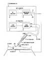
- FIG. 1depicts an electrosurgical apparatus in a monopolar mode with a single glow blade for use with a patient, in accordance with embodiments of the present invention.
- the electrosurgical unit apparatus of FIG. 1may be powered by alternating current (AC) power, direct current (DC) power such via batteries (e.g., isolated rechargeable batteries), or by a combination of AC power and DC power.
- ACalternating current
- DCdirect current
- the electrosurgical apparatus of FIG. 1comprises an electrosurgical unit 1 and a glow blade 11 , which may be contained within a single enclosure as shown in FIG. 1 or may be provided in separate enclosures as depicted in FIG. 8 described infra.
- the electrosurgical unit 1which comprises a radio frequency (RF) generator 30 and a power supply 31 , is electrically connected to the glow blade 11 by cable 15 which comprises conductors 15 A and 15 B.
- the power supply 31is configured such that there is no electrical current path from any output of the RF generator into the power supply 31 .
- the glow blade 11comprises a glow loop 6 which functions as a cutting probe that maintains an arc, wherein the arc cuts the target tissue.
- the glow loop 6is a loop of resistance wire heated to a glow (e.g., a cherry red color) by electrical current.
- the glowing of the glow loop 6may be analogous to a filament in a vacuum tube that is heated to promote electron emission from “filament to plate” or “cathode to plate” elements of the vacuum tube. Thus, it should be understood that the glow loop 6 is ready and able to give off electrons.
- the conductive element 507is electrically connected to the hot lead 8 of the RF generator 30 .
- the conductive element 507is RF excited such that a cutting tip 500 of the conductive element 507 cuts a local portion of tissue 32 of a patient 9 .
- the tissue 32is living tissue.
- the RF generator 30supplies the cutting energy and also causes RF heating of the tissue 32 . As the tissue 32 is cut, coagulation of tissue results from the RF heating, which immediately stops bleeding.
- the RF generator 30which supplies RF energy for tissue cutting, comprises a RF oscillator 2 and a high voltage (HV) amplifier 3 , wherein the RF oscillator 2 drives the high voltage amplifier 3 .
- the RF oscillator 2has an operating frequency between 100 KHz and 10 MHz (e.g., 500 KHz).
- the high voltage amplifier 3may generate variable wave shapes, including modulated types.
- FIG. 7depicts examples of radio frequency (RF) generator output wave shapes, in accordance with embodiments of the present invention.
- a continuous wavei.e., 100% duty cycle
- wave shape 41with amplitude of 100 volts RMS.
- a modulated shape of approximately 30% duty cycleis shown at wave shape 42 with higher amplitude than wave shape 41 .
- the duty cycle of the modulated shapeis defined as the ratio of the pulse duration in each cycle to the cycle period.
- a modulated shape of approximately 10% duty cycleis shown at wave shape 43 , with much higher amplitude than wave shape 41 .
- Different wave shapesmay be employed for different procedures (e.g., cutting with accompanying coagulation; coagulation without accompanying cutting; etc; etc.).
- modulated pulse shapes having duty cycles from about 20% to about 100%, which include the wave shapes 41 and 42 of FIG. 7may be employed for cutting with accompanying coagulation.
- modulated pulse shapes having duty cyclesfrom about 2% to about 20%, which include the wave shape 43 of FIG.
- wave shape 43may contain complex wave patterns, an alternate method to describe wave shape 43 is by a crest factor defined as a ratio of peak voltage to rms voltage, wherein values of the crest factor may range from about 5 to about 10 with peak voltages up to several thousand volts.
- wave shape 41may be alternatively employed for pure cutting without accompanying coagulation, which defines a “pure cutting” mode of operation.
- a feature of the glow bladeis that cutting with coagulation of highly vascular tissue can be achieved in an enhanced coagulation mode such as wave shape 43 . Conventional devices cannot cut a liver in any mode and achieve coagulation.
- the glow bladedoes not stick to the target tissue in the enhanced coagulation mode. This makes the enhanced coagulation mode of the present invention especially useful for concurrent cutting with coagulation, or for coagulation alone following an alternative cutting process that does not utilize the glow blade of the present invention.
- the wave shape 43is an example of an “enhanced coagulation waveform” which is defined as a waveform having a duty cycle from about 2% to about 20% and/or having a crest factor from about 5 to about 10.
- variable wave shapeshave an associated time-averaged output that may be varied from 50 to 500 volts (e.g., a sine wave with 100 volts RMS output voltage).
- Successful tissue cuttingwill occur, inter alia, with 100 volts while consuming only 5 watts of power, which implies a power range of 1.25 to 125 watts for the output voltage range of 50 to 500 volts.
- the lower output voltage of the RF generator 30as compared the much higher output voltage of at least 1000 volts of a conventional electrosurgical device, results in lower current through the target tissue and bulk of the patient 9 .
- the power supply 31comprises a glow oscillator 4 and glow amplifier 5 , wherein the glow oscillator 4 drives the glow amplifier 5 .
- the output of the glow amplifier 5is a low-voltage, high-current signal to heat up the conductive element 507 of the glow blade 11 .
- By adjusting the duty cycle of the glow oscillator 4one can adjust the temperature of conductive element 507 .
- the glow componentsi.e., the glow oscillator 4 and the glow amplifier 5
- the glow oscillator 4 and glow amplifier 5could be replaced by any suitable adjustable power source.
- the power supply 31is a DC source (e.g., one or more batteries) that drives a pulse amplifier to generate a pulse train that is sent to the conductive element 507 .
- the power of the pulse train from the power supply 31controls the temperature of the conductive element 507 .
- the power of the pulse train from the power supply 31may be varied by adjustment of the pulse amplitude, duty cycle and/or the pulse frequency.
- the power source for the power supply 31is an AC power source such as 115 VAC mains (e.g., the electrosurgical adapter 53 of FIG. 8 , described infra).
- the RF generator 30is electrically coupled to the power supply 31 .
- the hot lead 8 of the high voltage amplifier 3is electrically connected to both the output high side of the glow amplifier 5 and a first portion of the conductive element 507 via conductor 15 A.
- the output low side of glow amplifier 5is electrically connected to a remaining portion of the conductive element 507 via conductor 15 B.
- the circuit ground 10 of the high voltage amplifier 3is electrically connected to patient pad 7 which is in physical and electrical contact with the patient 9 such as, inter alia, the patient 9 lying or sitting on the pad 7 .
- the pad 7is an electrically conducting element that can be positioned in physical and electrical contact with any portion of the patient 9 , such as, inter alia, underneath the patient 9 in contact with the patient's back and/or buttock as in FIG. 1 , on or around an arm or leg of the patient 9 , on the chest of the patient 9 , etc.
- the hot lead 8 output (via circuit ground 10 ) of the RF generator 30is electrically connected to the pad 7 to facilitate an electric current flowing through the tissue of the patient 9 between the conductive element 507 and the pad 7 .
- the circuit ground 10is actually a return path for the hot lead 8 output and is sometimes called ground or minus terminal, where such ground is sometimes used as a convenience designation and does not necessarily imply any connection to earth ground.
- the RF generator 30may incorporate an output transformer where it is common practice to float output common from earth ground for safety reasons.
- RF currentflows from conductive element 507 through the target tissue, through the bulk of the patient 9 , and to the patient pad 7 .
- the cutting of the tissue 32occurs at the points of contact between the cutting tip 500 of the conductive element 507 and the patient 9 .
- tissue of the patient 9is cut.
- FIG. 5depicts an equivalent electric circuit representing the electrosurgical apparatus and patient of FIG. 1 , in accordance with embodiments of the present invention.
- the RF generator 30connects to conductive element 507 .
- the power supply 31is shown simplistically as a battery and connects across the section of resistance wire 504 .
- the conductive element 507is shown in electrical contact with patient tissue 32 , indicated as a resistive element. A portion of this resistive element adjacent to the patient pad 7 is the remainder of the patient which touches the patient pad 7 .
- the patient pad 7is electrically connected back to the RF generator 30 common at circuit ground 10 .
- the batteryheats up the section of resistance wire 504 and RF power is connected to the conductive element 507 which in turn transports energy to cut the tissue 32 of the patient 9 .
- the RF current pathis from the RF generator 30 to the conductive element 507 , through the tissue being cut, through the bulk of the patient, to the pad 7 and back to the RF generator 30 .
- the battery current pathis through the section of resistance wire 504 , so as to facilitate the transport of RF energy to the target tissue 32 .
- the RF current through the patient tissue 32achieves the cutting of the tissue 32 of the patient 9 . Because the applied RF voltage is substantially lower than the voltage of the conventional electrosurgical devices, lower and safer current flows through the patient as a result of usage of the single glow blade electrosurgical apparatus of the current invention.
- FIG. 3depicts the single glow blade 11 of FIG. 1 in greater detail, in accordance with embodiments of the present invention.
- Cable 15simultaneously provides both RF and glow power to conductive element 507 from RF generator 30 and glow amplifier 5 , respectively.
- a non-metallic handle 16supports the conductive element 507 and is mechanically fastened to conductive element 507 .
- the heated portion of the conductive element 507 near the cutting tip 500comprises resistance wire 504 in the form any functional geometry, protected by an enclosure of metal tubing 501 .
- the resistance wire 504may have the shape of a straight or curved wire or may represent a bulk electrically resistive material.
- the heated portion of the conductive element 507is near the cutting tip 500 of conductive element 507 where most efficient cutting occurs.
- the cutting tip 500has a flat surface configured to contact tissue. Heating power is supplied by cable 15 A via center conductor 502 , which is surrounded by insulator 503 and lies within the metallic tubing 501 (e.g., along the center line of the metallic tubing 501 ).
- the center conductor 502may comprise copper, but may alternatively comprise any other suitable electrically conductive metal or metallic alloy (e.g., nickel, chrome, stainless steel, etc.). Center conductor 502 supplies power to an end 508 of a section of resistance wire 504 which conducts heat to the cutting tip 500 . Another end 509 of the section of resistance wire 504 is electrically connected to the metallic tubing 501 by end crimp 506 .
- the metallic tubing 501is connected to cable 15 B as shown.
- the current path from cable 15 Ais down the center conductor 502 , through the section of resistance wire 504 and back along the outside of metallic tubing 501 to cable 15 B.
- Currentcauses the section of resistance wire 504 to heat up and thus the cutting tip 500 becomes hot and may glow.
- the metal tubing 501mechanically protects the section of resistance wire 504 .
- the metal tubing 501could be eliminated and the section of resistance wire 504 could function as the cutting element and assume numerous shapes such as a narrow or circular single loop or multiple loops.
- FIG. 8depicts an alternative electrosurgical apparatus in a single ended (i.e., monopolar) mode with a single glow blade for use with the patient 9 of FIG. 1 , in accordance with embodiments of the present invention.
- the electrosurgical apparatus of FIG. 8differs from the electrosurgical apparatus of FIGS. 1 and 5 in that: a commercial electrosurgical unit 50 of FIG. 8 replaces the RF generator 30 of FIGS. 1 and 5 ; and the electrosurgical adapter 53 of FIG. 8 replaces the power supply 31 of FIGS. 1 and 5 .
- the electrosurgical apparatus of FIG. 8 and the electrosurgical apparatus of FIGS. 1 and 5are essentially the same electrosurgical apparatus with respect to structure and functionality.
- the commercial electrosurgical unit 50is the RF power portion of a conventional electrosurgical apparatus used in the prior art.
- the glow blade 11(see FIG. 1 ) comprises the conductive element 507 and operates in conjunction with the electrosurgical adapter 53 .
- the commercial electrosurgical unit 50receives AC power as shown and has a high voltage output 51 and a common output 52 connected to RF circuit ground.
- the high voltage output 51is electrically connected, via the electrosurgical adapter 53 , to conductive element 507 which contacts the patient tissue 32 .
- the common output 52is electrically tied to the patient pad 7 .
- the electrosurgical adapter 53which converts AC power to a pulse train to provide power to the conductive element 507 , comprises a pulse generator/amplifier 56 and a RF isolation transformer 55 .
- An operator power control 54connects to the pulse generator/amplifier 56 and controls the power in the pulse train by varying pulse rate, duty cycle, or amplitude of the pulse train, which controls the temperature of the conductive element 507 .
- the RF isolation transformer 55allows power to be coupled from the pulse amplifier 56 to the conductive element 507 while providing a high impedance for any stray RF current flowing from the electrosurgical unit 50 .
- the transformer 55is wound with sufficient distance between primary and secondary coils to achieve the desired RF isolation and deliver the required power to be supplied to the conductive element 507 .
- the electrosurgical adapter 53may be replaced by a battery such as a battery representing the power supply 31 of FIGS. 1 and 5 , for use with the commercial electrosurgical unit 50 .
- the output from the electrosurgical adapter 53 of FIG. 8is analogous to the output from the power supply 31 of FIG. 1 .
- the output of the power supply 31is electrically decoupled from the AC power source of the RF generator 30 (e.g., by use of a battery as a power source of the power supply 31 ), which prevents unwanted RF power from flowing from the RF generator 30 to the power source of the power supply 31 .
- FIG. 1the output of the power supply 31 is electrically decoupled from the AC power source of the RF generator 30 (e.g., by use of a battery as a power source of the power supply 31 ), which prevents unwanted RF power from flowing from the RF generator 30 to the power source of the power supply 31 .
- FIG. 1the output of the power supply 31 is electrically decoupled from the AC power source of the RF generator 30 (e.g., by use of a battery as a power source of the power supply 31 ), which prevents unwanted RF power from flowing from the RF generator 30 to
- the output of the electrosurgical adapter 53is electrically decoupled from its AC power source and hence the power source of the electrosurgical unit 50 due to the output of the electrosurgical adapter 53 being decoupled by the RF isolation transformer 55 , which prevents unwanted RF power from flowing from the electrosurgical adapter 53 to the power source of the electrosurgical adapter 53 .
- the single glow blademay be used for rapid coagulation of tissue (without accompanying cutting of tissue) in order to stop bleeding immediately (e.g.; to stops uncontrolled bleeding of soldiers wounded in combat).
- the conductive element 507may be may be brushed along the surface of the tissue being coagulated (e.g., moved in a brushing-type motion in a direction that is about parallel to the surface of the tissue being coagulated, with actual contact or with a small gap; e.g., about in the direction 62 in FIG. 1 ).
- successful coagulation of tissue(without accompanying cutting of tissue) will occur with output power from the RF generator in a range of 1.25 to 125 watts.
- the RF generator 30 and the power supply 31are configured to operate concurrently, while the conductive element 507 is heated to a glow, to supply both sufficient RF power and associated electrical current across the living tissue 32 for cutting and/or coagulating the living tissue 32 by the conductive element 507 .
- the inventor of the present inventionhas determined that the single glow blade embodiment of the present invention may be beneficially employed in a non-glowing mode for the conductive element, as an improvement over conventional electrosurgical devices of the prior art, if the single glow blade embodiment is implemented as described supra except that the conductive element 507 performs cutting and/or coagulation of tissue at a temperature below the minimum glow temperature of the material of the conductive element 507 (e.g., at a temperature in a range of about 300° F. to just below the minimum glow temperature).
- the minimum glow temperature of the materialis defined as the minimum temperature at which the material glows (i.e., emits electromagnetic radiation in the visible portion of the electromagnetic spectrum).
- the bipolar glow blade embodimentprovides an alternative mode of operation that totally eliminates the patient pad of the single glow blade and eliminates associated currents which would otherwise travel through the patient's body.
- Two heated elements, or one heated element and one non-heated elementare placed, side by side, nearly touching each other and one or both made to glow.
- the RF generatoris connected across the two elements.
- the heated elementsare resistive elements. When the elements touch the patient's tissue, current flows from one element to the other element via the tissue that contacts the tip of the elements. If this approach were attempted with a conventional electrosurgical technology in a blend or coagulation mode using unheated elements, the required higher voltage would arc and short one element to the other due to carbon and tissue debris between the elements.
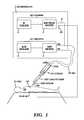
- FIG. 2depicts an electrosurgical apparatus configured for bipolar operation with a bipolar glow blade for use with a patient, in accordance with embodiments of the present invention.
- the electrosurgical unit apparatus of FIG. 2may be powered by alternating current (AC) power, direct current (DC) power such via batteries (e.g., isolated rechargeable batteries), or by a combination of AC power and DC power.
- ACalternating current
- DCdirect current
- the electrosurgical apparatus of FIG. 2comprises an electrosurgical unit 1 A and a bipolar glow blade 14 , which may combined in a single enclosure as shown in FIG. 2 or may be provided in separate enclosures as depicted in FIG. 9 described infra.
- the electrosurgical unit 1 Awhich comprises a radio frequency (RF) generator 30 , a power supply 31 A, and a power supply 31 B, is electrically connected to the bipolar glow blade 14 by cable 21 and cable 22 , respectively.
- the power supply 31 Ais analogous to the power supply 31 of FIG. 1 and the power supply 31 B is an added power supply which may be similar to, or identical with, the power supply 31 A.
- Cable 21comprises conductors 21 A and 21 B.
- Cable 22comprises conductors 22 A and 22 B.
- the power supply 31 Ais configured such that there is no electrical current path from any output of the RF generator into the power supply 31 A.
- the bipolar glow blade 14comprises a dual element 45 comprising a conductive element 507 a and a conductive element 507 b .
- the conductive element 507 ais heated and the conductive element 507 b is either heated or non-heated.
- the bipolar glow blade 14functions as a cutting probe that maintains an arc, wherein the arc cuts the target tissue.
- the patient pad 7has been eliminated in FIG. 2 , and the RF cutting voltage appears from conductive element 507 a (which is heated to a glow) to conductive element 507 b (which is either heated or non-heated).
- the conductive elements 507 a and 507 b of dual glow blade 14come in contact with the patient tissue 32 (which is living tissue), cutting is achieved. As the tissue 32 is cut, coagulation of tissue results from the RF heating, which immediately stops bleeding.
- Cable 21 A and 21 Bsupply both heating and RF power to conductive element 507 a in a manner similar to the heating supplied by cables 15 A and 15 B to the conductive element 507 of FIG. 3 .
- Cable 22 A and 22 Bsupply both heating power (if employed) and RF power return to element 507 b in a manner similar to the heating supplied by cables 15 A and 15 B to the conductive element 507 of FIG. 3 .
- the bipolar glow blade 14may have a metal tubing and non-metallic handle similar to the metal tubing 501 and the non-metallic handle 16 depicted for the single glow blade 11 in FIG. 3 .
- the glow blade 14may employ two assemblies similar to the glow blade 11 of FIG. 3 , However, FIG. 2 shows the conductive elements 507 a and 507 b schematically as simple electrical loops.
- the RF generator 30which supplies RF energy for tissue cutting, comprises a RF oscillator 2 and a high voltage (HV) amplifier 3 , wherein the RF oscillator 2 drives the high voltage amplifier 3 .
- the RF oscillator 2has an operating frequency between 100 KHz and 10 MHz (e.g., 500 KHz).
- the high voltage amplifier 3generates variable wave shapes, including modulated types.
- the high voltage amplifier 3generates variable wave shapes, including modulated types.
- FIG. 7depicts examples of radio frequency (RF) generator output wave shapes, in accordance with embodiments of the present invention.
- a continuous wavei.e., 100% duty cycle
- wave shape 41with amplitude of 100 volts RMS.
- a modulated shape of approximately 30% duty cycleis shown at wave shape 42 with higher amplitude than wave shape 41 .
- the duty cycle of the modulated shapeis defined as the ratio of the pulse duration in each cycle to the cycle period.
- a modulated shape of approximately 10% duty cycleis shown at wave shape 43 , with much higher amplitude than wave shape 41 .
- Different wave shapesmay be employed for different procedures (e.g., cutting with accompanying coagulation; coagulation without accompanying cutting; etc; etc.).
- modulated pulse shapes having duty cycles from about 20% to about 100%, which include the wave shapes 41 and 42 of FIG. 7may be employed for cutting with accompanying coagulation.
- modulated pulse shapes having duty cyclesfrom about 2% to about 20%, which include the wave shape 43 of FIG.
- wave shape 43may contain complex wave patterns, an alternate method to describe wave shape 43 is by a crest factor defined as a ratio of peak voltage to rms voltage, wherein values of the crest factor may range from about 5 to about 10 with peak voltages up to several thousand volts.
- wave shape 41may be alternatively employed for pure cutting without accompanying coagulation, which defines the “pure cutting” mode of operation.
- a key feature of the glow bladeis that cutting with coagulation of highly vascular tissue can be achieved in an enhanced coagulation mode such as wave shape 43 . Conventional devices cannot cut a liver in any mode and achieve coagulation.
- the glow bladeeasily cuts live liver with coagulation and does not stick to the target tissue in the enhanced coagulation mode. This makes the enhanced coagulation mode of the present invention especially useful for concurrent cutting with coagulation, or for coagulation alone following an alternative cutting process that does not utilize the glow blade of the present invention.
- the wave shape 43is an example of an “enhanced coagulation waveform” defined supra.
- variable wave shapeshave an associated time-averaged output that may be varied from 50 to 500 volts (e.g., a sine wave with 100 volts RMS output voltage).
- Successful tissue cuttingwill occur, inter alia, with 100 volts while consuming only 5 watts of power, which implies a power range of 1.25 to 125 watts for the output voltage range of 50 to 500 volts.
- the lower output voltage of the RF generator 30as compared the much higher output voltage of at least 1000 volts of a conventional electrosurgical device, results in lower current through the target tissue and bulk of the patient 9 .
- the power supply 31 Acomprises the glow oscillator 4 and glow amplifier 5 , wherein the glow oscillator 4 drives the glow amplifier 5 .
- the output of the glow amplifier 5is a low-voltage, high-current signal to heat up the conductive element 507 a of the glow blade 14 .
- By adjusting the duty cycle of the glow oscillator 4one can adjust the temperature of conductive element 507 a .
- the glow componentsi.e., the glow oscillator 4 and the glow amplifier 5
- the glow oscillator 4 and glow amplifier 5could be replaced by any suitable adjustable power source.
- the power supply 31 Ais powered by a DC source (e.g., one or more batteries) that drives a pulse amplifier to generate a pulse train that is sent to the conductive element 507 a .
- the power of the pulse train from the power supply 31 Acontrols the temperature of the conductive element 507 a .
- the power of the pulse train from the power supply 31 Amay be varied by adjustment of the pulse amplitude, duty cycle and/or the pulse rate.
- the power source for the power supply 31 Ais an AC power source such as 115 VAC mains (e.g., the electrosurgical adapter 53 A of FIG. 9 , described infra).
- the power supply 31 Bcomprises the glow oscillator 12 and glow amplifier 13 , wherein the glow oscillator 12 drives the glow amplifier 13 .
- the conductive element 507 bmay be heated or non-heated when used for cutting and/or coagulation.
- the output of the glow amplifier 13is a low-voltage, high-current signal to heat up the conductive element 507 b of the glow blade 14 .
- the glow componentsi.e., the glow oscillator 12 and the glow amplifier 13
- the power supply 31 Bis a DC source (e.g., one or more batteries) that drives a pulse amplifier to generate a pulse train that is sent to the conductive element 507 b .
- the power of the pulse train from the power supply 31 Bcontrols the temperature of the conductive element 507 b , which controls the temperature of the conductive element 507 b .
- the power of the pulse train from the power supply 31 Bmay be varied by adjustment of the pulse amplitude, duty cycle and/or the pulse rate.
- the power source for the power supply 31 Bis an AC power source such as 115 VAC mains (e.g., the electrosurgical adapter 53 B of FIG. 9 , described infra).
- the RF generator 30is electrically coupled to the power supplies 31 A and 31 B.
- the hot lead 8 of the high voltage amplifier 3is electrically connected to the high side of the glow amplifier 5 as in FIG. 1 and also to the conductive element 507 a .
- the low side of the high voltage amplifier 3is electrically connected in FIG. 2 to an internal circuit ground 10 A which is also electrically connected to the low side of the glow amplifier 13 and to conductive element 507 b .
- Outputs of the glow amplifier 5 and the glow amplifier 13are electrically connected to and across the resistive elements within conductive elements 507 a and 507 b of the dual glow blade 14 via cable 21 and 22 , respectively.
- FIG. 6depicts an equivalent electric circuit representing the electrosurgical apparatus and patient of FIG. 2 , in accordance with embodiments of the present invention.
- the high side of the RF generator 30is electrically connected to conductive element 507 a .
- the low side or common of the RF generator 30is electrically connected to conductive element 507 b .
- the power supplies 31 A and 31 Bare represented simplistically as batteries and heat the conductive elements but may alternatively be represented by AC power sources.
- the power supplies 31 A and 31 Bheat up the conductive elements, while the RF generator 30 provides energy for tissue cutting.
- the outputs of each respective supply 31 A and 31 Bare reversible; i.e.; high can be swapped with low and vice versa.
- the conductive elements 507 a and 507 bare in physically proximity and are separated by a gap that is equal to the minimum distance or separation between the conductive elements 507 a and 507 b .
- the range of gap sizethat may be beneficially used and depends on the nature of the surgery and the tissue being cut.
- the conductive elements 507 a and 507 bmay have any functional geometry as discussed infra in conjunction with FIG. 4B .
- An exemplary but not limiting range of gap sizesis 0.010 inch to 1 inch.
- FIGS. 4A , 4 B, and 4 Cdepict conductive elements 507 a and 507 b of the bipolar glow blade 14 of FIG. 2 in various geometric configurations, in accordance with embodiments of the present invention.
- the size and shape of conductive elements 507 a and 507 bmay vary depending on the type of surgical procedure and other factors such as durability and cost.
- the conductive elements 507 a and 507 bmay exist in any functional geometry that is suitable for cutting and/or coagulating tissue.
- the conductive elements 507 a and 507 b depicted in FIGS. 4A , 4 B, and 4 Care merely illustrative and do not limit the scope of possible geometries for conductive elements 507 a and 507 b.
- conductive elements 507 a and 507 bare each linear elements which are parallel to each other as in FIG. 2 .
- the conductive elements 507 a and 507 bare separated by gap 20 .
- the conductive elements 507 a and 507 bmay have equal or unequal lengths.
- conductive element 507 bis longer and thicker than conductive element 507 a in FIG. 2 .
- the shorter conductive element 507 acuts and/or coagulates while the longer conductive element 507 b is unheated.
- conductive elements 507 a and 507 bare each linear elements which form an acute angle with respect to each other to each other.
- the conductive elements 507 a and 507 bare separated by gap 20 .
- the conductive elements 507 a and 507 bmay be projected to intersect in a point.
- the conductive elements 507 a and 507 bmay have equal or unequal lengths.
- conductive element 507 bmay be longer than conductive element 507 a .
- the shorter conductive element 507 acuts and/or coagulates while the shorter conductive element 507 b is unheated.
- the conductive elements 507 a and 507 bmay be coplanar or may alternatively be non-coplanar.
- conductive elements 507 a and 507 bare loops which may be parallel or non-parallel to each other or co-linear or co-planar.
- the conductive elements 507 a and 507 bare separated by gap 20 .
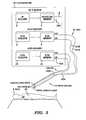
- FIG. 9depicts an alternative electrosurgical apparatus configured for bipolar operation with a bipolar glow blade for use with a patient, in accordance with embodiments of the present invention.
- the electrosurgical apparatus of FIG. 9differs from the electrosurgical apparatus of FIGS. 2 and 6 in that: a commercial electrosurgical unit 50 of FIG. 9 replaces the RF generator 30 of FIGS. 2 and 6 ; and the electrosurgical adapters 53 A and 53 B of FIG. 9 replace the power supplies 31 A and 31 B, respectively, of FIGS. 2 and 6 .
- the electrosurgical apparatus of FIG. 9 and the electrosurgical apparatus of FIGS. 2 and 6are essentially the same electrosurgical apparatus with respect to structure and functionality.
- the commercial electrosurgical unit 50is the RF power portion of a conventional electrosurgical apparatus used in the prior art.
- the bipolar glow blade 14(see FIG. 2 ) comprises the conductive elements 507 a and 507 b and operates in conjunction with the electrosurgical adapters 53 A and 53 B.
- the commercial electrosurgical unit 50receives AC power as shown and has a high voltage output 51 and a common output 52 .
- the high voltage output 51is electrically connected, via the electrosurgical adapter 53 A, to conductive element 507 a which contacts the patient tissue 32 .
- the common output 52is electrically connected, via the electrosurgical adapter 53 B to conductive element 507 b , or alternatively conductive element 507 b is non-heated, such that conductive element 507 b contacts the patient tissue 32 .
- the electrosurgical adapter 53 Awhich converts AC power to a pulse train to provide power to the conductive element 507 a , comprises a pulse generator/amplifier 56 A and an RF isolation transformer 55 A.
- An operator power control 54 Aconnects to the pulse generator/amplifier 56 A and controls the power in the pulse train by varying pulse rate, duty cycle, or amplitude of the pulse train, which controls the temperature of the conductive element 507 a .
- the RF isolation transformer 55 Aallows power to be coupled from the pulse amplifier 56 A to the conductive element 507 a while providing a high impedance for any stray RF current flowing from the electrosurgical unit 50 .
- the transformer 55 Ais wound with sufficient distance between primary and secondary coils to achieve the desired RF isolation and deliver the required power to be supplied to the conductive element 507 a .
- the electrosurgical adapter 53 Amay be replaced by a battery such as a battery representing the power supply 31 A of FIGS. 2 and 6 , for use with the commercial electrosurgical unit 50 .
- Power to the conductive element 507 ais supplied via the secondary of the isolation transformer 55 A.
- the electrosurgical adapter 53 Bwhich converts AC power to a pulse train to provide power to the conductive element 507 b , comprises a pulse generator/amplifier 56 B and an RF isolation transformer 55 B.
- An operator power control 54 Bconnects to the pulse generator/amplifier 56 B and controls the power in the pulse train by varying pulse rate, duty cycle, or amplitude of the pulse train, which controls the temperature of the conductive element 507 b .
- the RF isolation transformer 55 Ballows power to be coupled from the pulse amplifier 56 B to the conductive element 507 b while providing a high impedance for any stray RF current flowing from the electrosurgical unit 50 .
- the transformer 55 Bis wound with sufficient distance between primary and secondary coils to achieve the desired RF isolation and deliver the required power to be supplied to the conductive element 507 b .
- the electrosurgical adapter 53 Bmay be replaced by a battery such as a battery representing the power supply 31 A of FIGS. 2 and 6 , for use with the commercial electrosurgical unit 50 .
- Power to the conductive element 507 bis supplied via the secondary of the isolation transformer 55 B.
- the output from the electrosurgical adapters 53 A and 53 B of FIG. 9is analogous to the output from the power supplies 31 A and 31 B, respectively, of FIG. 2 .
- the output of the power supplies 31 A and 31 Bare electrically decoupled from the AC power source of the RF generator 30 (e.g., by use of a battery as a power source of the power supplies 31 A and 31 B), which prevents unwanted RF power from flowing from the RF generator 30 to the power source of the power supply 31 .
- FIG. 2the output of the power supplies 31 A and 31 B are electrically decoupled from the AC power source of the RF generator 30 (e.g., by use of a battery as a power source of the power supplies 31 A and 31 B), which prevents unwanted RF power from flowing from the RF generator 30 to the power source of the power supply 31 .
- the output of the electrosurgical adapter 53is electrically decoupled from its AC power source and hence the power source of the electrosurgical unit 50 due to the output of the electrosurgical adapter 53 being decoupled from by the RF isolation transformer 55 , which prevents unwanted RF power from flowing from the electrosurgical adapter 53 to the power source of the electrosurgical adapter 53 .
- the bipolar glow blademay be used for rapid coagulation of tissue (without accompanying cutting of tissue) in order to stop bleeding immediately (e.g.; to stops uncontrolled bleeding of soldiers wounded in combat).
- the conductive elements 507 a and 507 bmay be brushed along the surface of the tissue being coagulated (e.g., moved in a brushing-type motion in a direction that is about parallel to the surface of the tissue being coagulated, with actual contact or with a small gap; e.g., about in the direction 62 in FIG. 2 ).
- successful coagulation of tissuewill occur with output power from the RF generator in a range of 1.25 to 125 watts.
- the RF generator 30 and the power supplies 31 A and 31 Bare configured to operate concurrently, while the conductive elements 507 a and 507 b (or conductive element 507 a only) are heated to a glow, to supply both sufficient RF power and associated electrical current across the living tissue 32 for cutting and/or coagulating the living tissue 32 by the conductive elements 507 a and 507 b.
- the bipolar glow blade embodiment of the present inventionmay be beneficially employed in a non-glowing mode for the conductive elements, as an improvement over conventional electrosurgical devices of the prior art, if the dual glow blade embodiment is implemented as described supra except that the conductive elements 507 a and 507 b perform cutting and/or coagulation of tissue at a temperature below the minimum glow temperature of the material of the conductive elements (e.g., at a temperature in a range of about 300° F. to just below the minimum glow temperature).
- the minimum glow temperature of the materialis defined as the minimum temperature at which the material glows (i.e., emits electromagnetic radiation in the visible portion of the electromagnetic spectrum).
- FIG. 10depicts a proxipolar mode of electrosurgical cutting, in accordance with embodiments of the present invention.
- the proxipolar mode of cutting and coagulationhas features of both monopolar and bipolar with respect to RF return connection positions on the patient 9 .
- FIG. 10is similar to FIG. 1 except that a tissue hook 700 replaces the patient pad 7 of FIG. 1 as an electrically conducting element for the RF return path back to circuit ground 10 .
- the tissue hook 700is located proximate to where the tissue is being cut and/or coagulated by conductive element 507 (i.e., from 0.1 inches to 12 inches from where the tissue is being cut and/or coagulated as measured along the exterior surface of the tissue).
- the tissue hook 700is located remote from where the tissue is being cut and/or coagulated by conductive element 507 (i.e., greater than 12 inches from where the tissue is being cut and/or coagulated as measured along the exterior surface of the tissue). In one embodiment, the tissue hook 700 resembles a fishhook without a barb. Generally, the tissue hook 700 is an electrically conducting element that can be fastened to the tissue 32 to prevent relative motion between the tissue hook 700 at a location in the tissue 32 where the tissue hook 700 is fastened to the tissue 32 and may puncture or clamp the tissue 32 . This could be as close as 1 inch to the incision, depending on characteristics of the tissue 32 and requirements of the surgery.
- the tissue hook 700can be employed in lieu of a patient pad 7 , because the heated blade technology consumes a compatibly lower power, and a smaller surface area of patient tissue contact is adequate for RF return.
- the conductive element 507may be employed in the proxipolar mode as an unheated cutting element. Since the tissue hook 700 may have any geometric shape that enables the tissue hook 700 to be fastened to the tissue 32 , the tissue hook 700 could take numerous forms, such as a hook, clip, clamp, needle, or other tissue contact means.
- An advantage of using the tissue hook 700 instead of the patient pad 7is that the RF current in the patient 9 flows primarily from the conductive element 507 to the tissue hook 700 . Essentially no currents flow through sensitive tissue elsewhere in the patient 9 .
- FIG. 11depicts a circumpolar operational mode for tumor removal, in accordance with embodiments of the present invention.
- the circumpolar mode for tumor removalis an application of the proxipolar mode, wherein the tissue hook 700 is placed in the tissue of a tumor 525 targeted for excision.
- the tumor 525is disposed within tissue 523 .
- the tissue hook 700is placed about in the center 521 of the tumor 525 or in other tissue being excised.
- the conductive element 507circumscribes a path 522 around the tumor 525 as the conductive element 507 excises the tumor 525 .
- the RF current flowing through the tissueflows primarily from the conductive element 507 through the tumor 525 to the tissue hook 700 , which eliminates unwanted currents flowing, for example, through sensitive brain tissue located near a brain tumor when surgically removing such tumor.
- the glow blademay alternatively be heated by other heating mechanisms using alternative energy sources (e.g., laser heating, ultrasonic heating, flame heating, plasma heating, etc.) in a glowing mode or a non-glowing mode to implement the embodiments described herein for cutting and/or coagulating living tissue of a mammal.
- alternative energy sourcese.g., laser heating, ultrasonic heating, flame heating, plasma heating, etc.
- the scope of the present inventionincludes any method of using a heated glow blade to cut and/or coagulate living tissue of a mammal, regardless of the method by which the glow blade is heated.
- FIGS. 12 and 13illustrate infra alternative energy sources for heating the glow blade of the present invention.
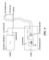
- FIG. 12depicts the electrosurgical apparatus in the monopolar mode of FIG. 1 with the power supply 31 being replaced by an alternative heating source, namely an energy source 550 and accompanying energy source controller 552 , in accordance with embodiments of the present invention.
- the energy source 550is controlled by the energy source controller 552 .
- the conductor cable 15electrically couples the RF generator to the glow blade 11 .
- the energy source 550comprises any energy source configured to focus an energy beam 551 on the cutting tip 500 with sufficient energy to heat the cutting tip 500 to a glow or to a non-glowing temperature sufficient for cutting and/or coagulating tissue of the patient 9 .
- the energy source 550is mechanically affixed to the glow blade 11 (e.g., at the metal tubing 501 or the non-metallic handle 16 shown in FIG. 3 ) in manner that constrains the energy beam 551 to point toward the cutting tip 500 continuously while the glow blade is being moved.
- the energy source 550is a source of laser radiation whose wavelength and power are configured to sufficiently heat the cutting tip 500 to for cutting and/or coagulating tissue of the patient 9 .
- the energy source 550is a source of sonic radiation whose frequency and power are configured to sufficiently heat the cutting tip 500 to for cutting and/or coagulating tissue of the patient 9 .
- the energy source 550provides flame radiation configured to sufficiently heat the cutting tip 500 for cutting and/or coagulating tissue of the patient 9 .
- the energy source 550provides plasma configured to sufficiently heat the cutting tip 500 for cutting and/or coagulating tissue of the patient 9 .
- the energy source 550generally represents any energy source coupled to the glow blade 11 (e.g., mechanically affixed to the glow blade) that can provide energy to the cutting tip 500 , said provided energy being of sufficient magnitude to heat the cutting tip 500 to a glow or to a non-glowing temperature sufficient for cutting and/or coagulating tissue of the patient 9 by the glow blade 11 in accordance with the present invention as described supra.
- FIG. 13depicts the electrosurgical apparatus in the bipolar mode of FIG. 2 with the power supplies 31 A and 31 B being replaced by an alternative heating sources, namely energy sources 550 a and 550 b along with accompanying energy source controllers 552 a and 552 b , in accordance with embodiments of the present invention.
- the energy sources 550 a and 550 bare controlled by the energy source controllers 552 a and 552 b , respectively.
- the conductor cables 21 c and 21 delectrically couple the RF generator 30 to the bipolar glow blade 14 .
- the energy sources 550 a and 550 bcomprises any energy source configured to focus energy beams 551 a and 551 b on the conductive elements 507 a and 507 b with sufficient energy to heat the conductive elements 507 a and 507 b to a glow or to a non-glowing temperature sufficient for cutting and/or coagulating tissue of the patient 9 .
- the energy sources 550 a and 550 bare mechanically affixed to the glow blade 14 (e.g., at the metal tubing or non-metallic handle similar to the metal tubing 501 or the non-metallic handle 16 shown in FIG.
- the sources 550 a and 550 bare sources of laser radiation whose wavelength and power are sufficiently configured to heat the conductive elements 507 a and 507 b , respectively, for cutting and/or coagulating tissue of the patient 9 .
- the energy sources 550 a and 550 bare ultrasound sources of sonic radiation whose frequency and power are sufficiently configured to heat the conductive elements 507 a and 507 b , respectively, for cutting and/or coagulating tissue of the patient 9 .
- the energy sources 550 a and 550 bprovide flame radiation configured to sufficiently heat the conductive elements 507 a and 507 b for cutting and/or coagulating tissue of the patient 9 . In one embodiment, the energy sources 550 a and 550 b provide plasma configured to sufficiently heat the conductive elements 507 a and 507 b for cutting and/or coagulating tissue of the patient 9 . In one embodiment only one energy source is employed to heat one conductive element while the second conductive element is unheated.
- the energy sources 550 a and 550 bgenerally represents any energy sources coupled to the glow blade 14 (e.g., mechanically affixed to the glow blade) that can provide energy to conductive elements 507 a and 507 , said provided energy being of sufficient magnitude to heat the conductive elements 507 a and 507 b to a glow or to a non-glowing temperature sufficient for cutting and/or coagulating tissue of the patient 9 by the glow blade 14 in accordance with the present invention as described supra.
- the electrosurgical apparatus of the present inventionis fully operational.
- the conductive elementsare constructed with an outer member of stainless steel tubing. Internal to the tubing is a heated nickel chrome resistance wire. Both the monopolar and bipolar glow blades have been used successfully to cut and coagulate live pig tissue.
- a conventional electrosurgical generatorwas set up in an enhanced coagulation mode, crest factor equal to 8, and was employed in conjunction with the electrosurgical adapter of the present invention to cut and coagulate live pig liver using a glow blade. When cutting, the single glow blade was moved across the target tissue similar to using a conventional knife. In practice, however, some back and forth motion may be employed.
- the elementmay be placed over the tissue and its edge gently pressed against and into the tissue to create a cut.
- undercuti.e., to move the glow blade under the target tissue, where the blade may be shaped as required to first penetrate the target tissue, followed by cutting under the target tissue. Cutting along a curve is practical, since the glow blade may be easily bent by a user (e.g., a surgeon) to the required curvature.
Landscapes
- Health & Medical Sciences (AREA)
- Surgery (AREA)
- Engineering & Computer Science (AREA)
- Life Sciences & Earth Sciences (AREA)
- Biomedical Technology (AREA)
- Otolaryngology (AREA)
- Nuclear Medicine, Radiotherapy & Molecular Imaging (AREA)
- Plasma & Fusion (AREA)
- Physics & Mathematics (AREA)
- Heart & Thoracic Surgery (AREA)
- Medical Informatics (AREA)
- Molecular Biology (AREA)
- Animal Behavior & Ethology (AREA)
- General Health & Medical Sciences (AREA)
- Public Health (AREA)
- Veterinary Medicine (AREA)
- Surgical Instruments (AREA)
Abstract
Description
Claims (26)
Priority Applications (1)
| Application Number | Priority Date | Filing Date | Title |
|---|---|---|---|
| US12/023,562US8382748B2 (en) | 2006-01-03 | 2008-01-31 | High efficiency, precision electrosurgical apparatus and method |
Applications Claiming Priority (3)
| Application Number | Priority Date | Filing Date | Title |
|---|---|---|---|
| US75590006P | 2006-01-03 | 2006-01-03 | |
| US11/552,581US7922713B2 (en) | 2006-01-03 | 2006-10-25 | High efficiency, precision electrosurgical apparatus and method |
| US12/023,562US8382748B2 (en) | 2006-01-03 | 2008-01-31 | High efficiency, precision electrosurgical apparatus and method |
Related Parent Applications (1)
| Application Number | Title | Priority Date | Filing Date |
|---|---|---|---|
| US11/552,581Continuation-In-PartUS7922713B2 (en) | 2006-01-03 | 2006-10-25 | High efficiency, precision electrosurgical apparatus and method |
Publications (2)
| Publication Number | Publication Date |
|---|---|
| US20080119841A1 US20080119841A1 (en) | 2008-05-22 |
| US8382748B2true US8382748B2 (en) | 2013-02-26 |
Family
ID=46330094
Family Applications (1)
| Application Number | Title | Priority Date | Filing Date |
|---|---|---|---|
| US12/023,562Active2030-01-03US8382748B2 (en) | 2006-01-03 | 2008-01-31 | High efficiency, precision electrosurgical apparatus and method |
Country Status (1)
| Country | Link |
|---|---|
| US (1) | US8382748B2 (en) |
Cited By (135)
| Publication number | Priority date | Publication date | Assignee | Title |
|---|---|---|---|---|
| US9168054B2 (en) | 2009-10-09 | 2015-10-27 | Ethicon Endo-Surgery, Inc. | Surgical generator for ultrasonic and electrosurgical devices |
| WO2015175400A2 (en) | 2014-05-12 | 2015-11-19 | Gyrus Acmi, Inc. | Resistively heated electrosurgical device |
| US9283045B2 (en) | 2012-06-29 | 2016-03-15 | Ethicon Endo-Surgery, Llc | Surgical instruments with fluid management system |
| US9326788B2 (en) | 2012-06-29 | 2016-05-03 | Ethicon Endo-Surgery, Llc | Lockout mechanism for use with robotic electrosurgical device |
| US9339289B2 (en) | 2007-11-30 | 2016-05-17 | Ehticon Endo-Surgery, LLC | Ultrasonic surgical instrument blades |
| US9393037B2 (en) | 2012-06-29 | 2016-07-19 | Ethicon Endo-Surgery, Llc | Surgical instruments with articulating shafts |
| US9414853B2 (en) | 2007-07-27 | 2016-08-16 | Ethicon Endo-Surgery, Llc | Ultrasonic end effectors with increased active length |
| US9427249B2 (en) | 2010-02-11 | 2016-08-30 | Ethicon Endo-Surgery, Llc | Rotatable cutting implements with friction reducing material for ultrasonic surgical instruments |
| US9504483B2 (en) | 2007-03-22 | 2016-11-29 | Ethicon Endo-Surgery, Llc | Surgical instruments |
| US9504855B2 (en) | 2008-08-06 | 2016-11-29 | Ethicon Surgery, LLC | Devices and techniques for cutting and coagulating tissue |
| US9510850B2 (en) | 2010-02-11 | 2016-12-06 | Ethicon Endo-Surgery, Llc | Ultrasonic surgical instruments |
| US9636135B2 (en) | 2007-07-27 | 2017-05-02 | Ethicon Endo-Surgery, Llc | Ultrasonic surgical instruments |
| US9642644B2 (en) | 2007-07-27 | 2017-05-09 | Ethicon Endo-Surgery, Llc | Surgical instruments |
| US9649126B2 (en) | 2010-02-11 | 2017-05-16 | Ethicon Endo-Surgery, Llc | Seal arrangements for ultrasonically powered surgical instruments |
| US9700339B2 (en) | 2009-05-20 | 2017-07-11 | Ethicon Endo-Surgery, Inc. | Coupling arrangements and methods for attaching tools to ultrasonic surgical instruments |
| US9700343B2 (en) | 2012-04-09 | 2017-07-11 | Ethicon Endo-Surgery, Llc | Devices and techniques for cutting and coagulating tissue |
| US9713507B2 (en) | 2012-06-29 | 2017-07-25 | Ethicon Endo-Surgery, Llc | Closed feedback control for electrosurgical device |
| US9724118B2 (en) | 2012-04-09 | 2017-08-08 | Ethicon Endo-Surgery, Llc | Techniques for cutting and coagulating tissue for ultrasonic surgical instruments |
| US9737326B2 (en) | 2012-06-29 | 2017-08-22 | Ethicon Endo-Surgery, Llc | Haptic feedback devices for surgical robot |
| US9743947B2 (en) | 2013-03-15 | 2017-08-29 | Ethicon Endo-Surgery, Llc | End effector with a clamp arm assembly and blade |
| US9764164B2 (en) | 2009-07-15 | 2017-09-19 | Ethicon Llc | Ultrasonic surgical instruments |
| US9795405B2 (en) | 2012-10-22 | 2017-10-24 | Ethicon Llc | Surgical instrument |
| US9801648B2 (en) | 2007-03-22 | 2017-10-31 | Ethicon Llc | Surgical instruments |
| US9848901B2 (en) | 2010-02-11 | 2017-12-26 | Ethicon Llc | Dual purpose surgical instrument for cutting and coagulating tissue |
| US9848902B2 (en) | 2007-10-05 | 2017-12-26 | Ethicon Llc | Ergonomic surgical instruments |
| US9883884B2 (en) | 2007-03-22 | 2018-02-06 | Ethicon Llc | Ultrasonic surgical instruments |
| US9925003B2 (en) | 2012-02-10 | 2018-03-27 | Ethicon Endo-Surgery, Llc | Robotically controlled surgical instrument |
| US9962182B2 (en) | 2010-02-11 | 2018-05-08 | Ethicon Llc | Ultrasonic surgical instruments with moving cutting implement |
| US10010339B2 (en) | 2007-11-30 | 2018-07-03 | Ethicon Llc | Ultrasonic surgical blades |
| US10034704B2 (en) | 2015-06-30 | 2018-07-31 | Ethicon Llc | Surgical instrument with user adaptable algorithms |
| US10034684B2 (en) | 2015-06-15 | 2018-07-31 | Ethicon Llc | Apparatus and method for dissecting and coagulating tissue |
| US10154852B2 (en) | 2015-07-01 | 2018-12-18 | Ethicon Llc | Ultrasonic surgical blade with improved cutting and coagulation features |
| US10179022B2 (en) | 2015-12-30 | 2019-01-15 | Ethicon Llc | Jaw position impedance limiter for electrosurgical instrument |
| US10194973B2 (en) | 2015-09-30 | 2019-02-05 | Ethicon Llc | Generator for digitally generating electrical signal waveforms for electrosurgical and ultrasonic surgical instruments |
| US10201382B2 (en) | 2009-10-09 | 2019-02-12 | Ethicon Llc | Surgical generator for ultrasonic and electrosurgical devices |
| US10226273B2 (en) | 2013-03-14 | 2019-03-12 | Ethicon Llc | Mechanical fasteners for use with surgical energy devices |
| US10245064B2 (en) | 2016-07-12 | 2019-04-02 | Ethicon Llc | Ultrasonic surgical instrument with piezoelectric central lumen transducer |
| US10251664B2 (en) | 2016-01-15 | 2019-04-09 | Ethicon Llc | Modular battery powered handheld surgical instrument with multi-function motor via shifting gear assembly |
| USD847990S1 (en) | 2016-08-16 | 2019-05-07 | Ethicon Llc | Surgical instrument |
| US10278721B2 (en) | 2010-07-22 | 2019-05-07 | Ethicon Llc | Electrosurgical instrument with separate closure and cutting members |
| US10285724B2 (en) | 2014-07-31 | 2019-05-14 | Ethicon Llc | Actuation mechanisms and load adjustment assemblies for surgical instruments |
| US10285723B2 (en) | 2016-08-09 | 2019-05-14 | Ethicon Llc | Ultrasonic surgical blade with improved heel portion |
| US10321950B2 (en) | 2015-03-17 | 2019-06-18 | Ethicon Llc | Managing tissue treatment |
| US10335182B2 (en) | 2012-06-29 | 2019-07-02 | Ethicon Llc | Surgical instruments with articulating shafts |
| US10342602B2 (en) | 2015-03-17 | 2019-07-09 | Ethicon Llc | Managing tissue treatment |
| US10349999B2 (en) | 2014-03-31 | 2019-07-16 | Ethicon Llc | Controlling impedance rise in electrosurgical medical devices |
| US10357303B2 (en) | 2015-06-30 | 2019-07-23 | Ethicon Llc | Translatable outer tube for sealing using shielded lap chole dissector |
| US10357305B2 (en) | 2014-03-26 | 2019-07-23 | Venclose, Inc. | Venous disease treatment |
| US10376305B2 (en) | 2016-08-05 | 2019-08-13 | Ethicon Llc | Methods and systems for advanced harmonic energy |
| US10420579B2 (en) | 2007-07-31 | 2019-09-24 | Ethicon Llc | Surgical instruments |
| US10420580B2 (en) | 2016-08-25 | 2019-09-24 | Ethicon Llc | Ultrasonic transducer for surgical instrument |
| US10426507B2 (en) | 2007-07-31 | 2019-10-01 | Ethicon Llc | Ultrasonic surgical instruments |
| US10433899B2 (en) | 2015-01-13 | 2019-10-08 | Megadyne Medical Products, Inc. | Precision blade electrosurgical instrument |
| US10433900B2 (en) | 2011-07-22 | 2019-10-08 | Ethicon Llc | Surgical instruments for tensioning tissue |
| US10433898B2 (en) | 2015-01-13 | 2019-10-08 | Megadyne Medical Products, Inc. | Tapered precision blade electrosurgical instrument |
| US10441345B2 (en) | 2009-10-09 | 2019-10-15 | Ethicon Llc | Surgical generator for ultrasonic and electrosurgical devices |
| US10456193B2 (en) | 2016-05-03 | 2019-10-29 | Ethicon Llc | Medical device with a bilateral jaw configuration for nerve stimulation |
| US10463421B2 (en) | 2014-03-27 | 2019-11-05 | Ethicon Llc | Two stage trigger, clamp and cut bipolar vessel sealer |
| US10485607B2 (en) | 2016-04-29 | 2019-11-26 | Ethicon Llc | Jaw structure with distal closure for electrosurgical instruments |
| US10517627B2 (en) | 2012-04-09 | 2019-12-31 | Ethicon Llc | Switch arrangements for ultrasonic surgical instruments |
| US10524854B2 (en) | 2010-07-23 | 2020-01-07 | Ethicon Llc | Surgical instrument |
| US10537352B2 (en) | 2004-10-08 | 2020-01-21 | Ethicon Llc | Tissue pads for use with surgical instruments |
| US10543008B2 (en) | 2012-06-29 | 2020-01-28 | Ethicon Llc | Ultrasonic surgical instruments with distally positioned jaw assemblies |
| US10555769B2 (en) | 2016-02-22 | 2020-02-11 | Ethicon Llc | Flexible circuits for electrosurgical instrument |
| US10575892B2 (en) | 2015-12-31 | 2020-03-03 | Ethicon Llc | Adapter for electrical surgical instruments |
| US10595929B2 (en) | 2015-03-24 | 2020-03-24 | Ethicon Llc | Surgical instruments with firing system overload protection mechanisms |
| US10595930B2 (en) | 2015-10-16 | 2020-03-24 | Ethicon Llc | Electrode wiping surgical device |
| US10603064B2 (en) | 2016-11-28 | 2020-03-31 | Ethicon Llc | Ultrasonic transducer |
| US10639092B2 (en) | 2014-12-08 | 2020-05-05 | Ethicon Llc | Electrode configurations for surgical instruments |
| US10646269B2 (en) | 2016-04-29 | 2020-05-12 | Ethicon Llc | Non-linear jaw gap for electrosurgical instruments |
| USRE47996E1 (en) | 2009-10-09 | 2020-05-19 | Ethicon Llc | Surgical generator for ultrasonic and electrosurgical devices |
| US10702329B2 (en) | 2016-04-29 | 2020-07-07 | Ethicon Llc | Jaw structure with distal post for electrosurgical instruments |
| US10716615B2 (en) | 2016-01-15 | 2020-07-21 | Ethicon Llc | Modular battery powered handheld surgical instrument with curved end effectors having asymmetric engagement between jaw and blade |
| US10765470B2 (en) | 2015-06-30 | 2020-09-08 | Ethicon Llc | Surgical system with user adaptable techniques employing simultaneous energy modalities based on tissue parameters |
| US10779845B2 (en) | 2012-06-29 | 2020-09-22 | Ethicon Llc | Ultrasonic surgical instruments with distally positioned transducers |
| US10779848B2 (en) | 2006-01-20 | 2020-09-22 | Ethicon Llc | Ultrasound medical instrument having a medical ultrasonic blade |
| US10779879B2 (en) | 2014-03-18 | 2020-09-22 | Ethicon Llc | Detecting short circuits in electrosurgical medical devices |
| US10820920B2 (en) | 2017-07-05 | 2020-11-03 | Ethicon Llc | Reusable ultrasonic medical devices and methods of their use |
| US10835307B2 (en) | 2001-06-12 | 2020-11-17 | Ethicon Llc | Modular battery powered handheld surgical instrument containing elongated multi-layered shaft |
| US10842522B2 (en) | 2016-07-15 | 2020-11-24 | Ethicon Llc | Ultrasonic surgical instruments having offset blades |
| US10842580B2 (en) | 2012-06-29 | 2020-11-24 | Ethicon Llc | Ultrasonic surgical instruments with control mechanisms |
| US10856929B2 (en) | 2014-01-07 | 2020-12-08 | Ethicon Llc | Harvesting energy from a surgical generator |
| US10856896B2 (en) | 2005-10-14 | 2020-12-08 | Ethicon Llc | Ultrasonic device for cutting and coagulating |
| US10874418B2 (en) | 2004-02-27 | 2020-12-29 | Ethicon Llc | Ultrasonic surgical shears and method for sealing a blood vessel using same |
| US10881449B2 (en) | 2012-09-28 | 2021-01-05 | Ethicon Llc | Multi-function bi-polar forceps |
| US10893883B2 (en) | 2016-07-13 | 2021-01-19 | Ethicon Llc | Ultrasonic assembly for use with ultrasonic surgical instruments |
| US10898256B2 (en) | 2015-06-30 | 2021-01-26 | Ethicon Llc | Surgical system with user adaptable techniques based on tissue impedance |
| US10912603B2 (en) | 2013-11-08 | 2021-02-09 | Ethicon Llc | Electrosurgical devices |
| US10912580B2 (en) | 2013-12-16 | 2021-02-09 | Ethicon Llc | Medical device |
| US10925659B2 (en) | 2013-09-13 | 2021-02-23 | Ethicon Llc | Electrosurgical (RF) medical instruments for cutting and coagulating tissue |
| US10952759B2 (en) | 2016-08-25 | 2021-03-23 | Ethicon Llc | Tissue loading of a surgical instrument |
| US10987123B2 (en) | 2012-06-28 | 2021-04-27 | Ethicon Llc | Surgical instruments with articulating shafts |
| US11000328B2 (en) | 2016-11-09 | 2021-05-11 | Gyrus Acmi, Inc. | Resistively heated electrosurgical device |
| US11020140B2 (en) | 2015-06-17 | 2021-06-01 | Cilag Gmbh International | Ultrasonic surgical blade for use with ultrasonic surgical instruments |
| US11033292B2 (en) | 2013-12-16 | 2021-06-15 | Cilag Gmbh International | Medical device |
| US11051873B2 (en) | 2015-06-30 | 2021-07-06 | Cilag Gmbh International | Surgical system with user adaptable techniques employing multiple energy modalities based on tissue parameters |
| US11058447B2 (en) | 2007-07-31 | 2021-07-13 | Cilag Gmbh International | Temperature controlled ultrasonic surgical instruments |
| US11090104B2 (en) | 2009-10-09 | 2021-08-17 | Cilag Gmbh International | Surgical generator for ultrasonic and electrosurgical devices |
| US11129669B2 (en) | 2015-06-30 | 2021-09-28 | Cilag Gmbh International | Surgical system with user adaptable techniques based on tissue type |
| US11129670B2 (en) | 2016-01-15 | 2021-09-28 | Cilag Gmbh International | Modular battery powered handheld surgical instrument with selective application of energy based on button displacement, intensity, or local tissue characterization |
| US11229471B2 (en) | 2016-01-15 | 2022-01-25 | Cilag Gmbh International | Modular battery powered handheld surgical instrument with selective application of energy based on tissue characterization |
| US11266430B2 (en) | 2016-11-29 | 2022-03-08 | Cilag Gmbh International | End effector control and calibration |
| US11311326B2 (en) | 2015-02-06 | 2022-04-26 | Cilag Gmbh International | Electrosurgical instrument with rotation and articulation mechanisms |
| US11324527B2 (en) | 2012-11-15 | 2022-05-10 | Cilag Gmbh International | Ultrasonic and electrosurgical devices |
| US11337747B2 (en) | 2014-04-15 | 2022-05-24 | Cilag Gmbh International | Software algorithms for electrosurgical instruments |
| US11399855B2 (en) | 2014-03-27 | 2022-08-02 | Cilag Gmbh International | Electrosurgical devices |
| US11446078B2 (en) | 2015-07-20 | 2022-09-20 | Megadyne Medical Products, Inc. | Electrosurgical wave generator |
| US11452525B2 (en) | 2019-12-30 | 2022-09-27 | Cilag Gmbh International | Surgical instrument comprising an adjustment system |
| US11547471B2 (en) | 2019-03-27 | 2023-01-10 | Gyrus Acmi, Inc. | Device with loop electrodes for treatment of menorrhagia |
| US11589916B2 (en) | 2019-12-30 | 2023-02-28 | Cilag Gmbh International | Electrosurgical instruments with electrodes having variable energy densities |
| US11660089B2 (en) | 2019-12-30 | 2023-05-30 | Cilag Gmbh International | Surgical instrument comprising a sensing system |
| US11684412B2 (en) | 2019-12-30 | 2023-06-27 | Cilag Gmbh International | Surgical instrument with rotatable and articulatable surgical end effector |
| US11696776B2 (en) | 2019-12-30 | 2023-07-11 | Cilag Gmbh International | Articulatable surgical instrument |
| US11723716B2 (en) | 2019-12-30 | 2023-08-15 | Cilag Gmbh International | Electrosurgical instrument with variable control mechanisms |
| US11759251B2 (en) | 2019-12-30 | 2023-09-19 | Cilag Gmbh International | Control program adaptation based on device status and user input |
| US11779387B2 (en) | 2019-12-30 | 2023-10-10 | Cilag Gmbh International | Clamp arm jaw to minimize tissue sticking and improve tissue control |
| US11779329B2 (en) | 2019-12-30 | 2023-10-10 | Cilag Gmbh International | Surgical instrument comprising a flex circuit including a sensor system |
| US11786291B2 (en) | 2019-12-30 | 2023-10-17 | Cilag Gmbh International | Deflectable support of RF energy electrode with respect to opposing ultrasonic blade |
| US11812957B2 (en) | 2019-12-30 | 2023-11-14 | Cilag Gmbh International | Surgical instrument comprising a signal interference resolution system |
| US11911063B2 (en) | 2019-12-30 | 2024-02-27 | Cilag Gmbh International | Techniques for detecting ultrasonic blade to electrode contact and reducing power to ultrasonic blade |
| US11937863B2 (en) | 2019-12-30 | 2024-03-26 | Cilag Gmbh International | Deflectable electrode with variable compression bias along the length of the deflectable electrode |
| US11937866B2 (en) | 2019-12-30 | 2024-03-26 | Cilag Gmbh International | Method for an electrosurgical procedure |
| US11944366B2 (en) | 2019-12-30 | 2024-04-02 | Cilag Gmbh International | Asymmetric segmented ultrasonic support pad for cooperative engagement with a movable RF electrode |
| US11950797B2 (en) | 2019-12-30 | 2024-04-09 | Cilag Gmbh International | Deflectable electrode with higher distal bias relative to proximal bias |
| US11986201B2 (en) | 2019-12-30 | 2024-05-21 | Cilag Gmbh International | Method for operating a surgical instrument |
| US12023086B2 (en) | 2019-12-30 | 2024-07-02 | Cilag Gmbh International | Electrosurgical instrument for delivering blended energy modalities to tissue |
| US12053224B2 (en) | 2019-12-30 | 2024-08-06 | Cilag Gmbh International | Variation in electrode parameters and deflectable electrode to modify energy density and tissue interaction |
| US12064109B2 (en) | 2019-12-30 | 2024-08-20 | Cilag Gmbh International | Surgical instrument comprising a feedback control circuit |
| US12076006B2 (en) | 2019-12-30 | 2024-09-03 | Cilag Gmbh International | Surgical instrument comprising an orientation detection system |
| US12082808B2 (en) | 2019-12-30 | 2024-09-10 | Cilag Gmbh International | Surgical instrument comprising a control system responsive to software configurations |
| US12114912B2 (en) | 2019-12-30 | 2024-10-15 | Cilag Gmbh International | Non-biased deflectable electrode to minimize contact between ultrasonic blade and electrode |
| US12193698B2 (en) | 2016-01-15 | 2025-01-14 | Cilag Gmbh International | Method for self-diagnosing operation of a control switch in a surgical instrument system |
| US12262937B2 (en) | 2019-12-30 | 2025-04-01 | Cilag Gmbh International | User interface for surgical instrument with combination energy modality end-effector |
| US12336747B2 (en) | 2019-12-30 | 2025-06-24 | Cilag Gmbh International | Method of operating a combination ultrasonic / bipolar RF surgical device with a combination energy modality end-effector |
| US12343063B2 (en) | 2019-12-30 | 2025-07-01 | Cilag Gmbh International | Multi-layer clamp arm pad for enhanced versatility and performance of a surgical device |
Families Citing this family (15)
| Publication number | Priority date | Publication date | Assignee | Title |
|---|---|---|---|---|
| US8500727B2 (en) | 2008-05-13 | 2013-08-06 | Megadyne Medical Products, Inc. | Methods, systems, and devices for performing electrosurgical procedures |
| US9730749B2 (en) | 2009-04-17 | 2017-08-15 | Domain Surgical, Inc. | Surgical scalpel with inductively heated regions |
| US9107666B2 (en) | 2009-04-17 | 2015-08-18 | Domain Surgical, Inc. | Thermal resecting loop |
| US9131977B2 (en) | 2009-04-17 | 2015-09-15 | Domain Surgical, Inc. | Layered ferromagnetic coated conductor thermal surgical tool |
| US9078655B2 (en) | 2009-04-17 | 2015-07-14 | Domain Surgical, Inc. | Heated balloon catheter |
| US9265556B2 (en) | 2009-04-17 | 2016-02-23 | Domain Surgical, Inc. | Thermally adjustable surgical tool, balloon catheters and sculpting of biologic materials |
| US8932279B2 (en) | 2011-04-08 | 2015-01-13 | Domain Surgical, Inc. | System and method for cooling of a heated surgical instrument and/or surgical site and treating tissue |
| EP2704657A4 (en) | 2011-04-08 | 2014-12-31 | Domain Surgical Inc | IMPEDANCE ADAPTATION CIRCUIT |
| WO2012158722A2 (en) | 2011-05-16 | 2012-11-22 | Mcnally, David, J. | Surgical instrument guide |
| WO2013040255A2 (en) | 2011-09-13 | 2013-03-21 | Domain Surgical, Inc. | Sealing and/or cutting instrument |
| JP2015506729A (en) | 2011-12-06 | 2015-03-05 | ドメイン・サージカル,インコーポレーテッド | System and method for controlling power supply to a surgical instrument |
| US10448986B2 (en)* | 2013-09-27 | 2019-10-22 | Covidien Lp | Electrosurgical medical device with power modulation |
| US10219856B2 (en) | 2013-09-30 | 2019-03-05 | Donald J. Geisel | Heated resonant cutting device and method of use thereof |
| US10357306B2 (en) | 2014-05-14 | 2019-07-23 | Domain Surgical, Inc. | Planar ferromagnetic coated surgical tip and method for making |
| US20160296270A1 (en)* | 2015-04-10 | 2016-10-13 | Ethicon Endo-Surgery, Llc | Devices and methods for providing additional power to surgical devices |
Citations (7)
| Publication number | Priority date | Publication date | Assignee | Title |
|---|---|---|---|---|
| US4196734A (en) | 1978-02-16 | 1980-04-08 | Valleylab, Inc. | Combined electrosurgery/cautery system and method |
| US5046506A (en)* | 1990-02-09 | 1991-09-10 | Singer Medical Products, Inc. | Molded needle with adhesive |
| US5807392A (en) | 1995-03-02 | 1998-09-15 | Eggers; Philip E. | Resistively heated cutting and coagulating surgical instrument |
| US5885277A (en)* | 1994-07-15 | 1999-03-23 | Olympus Winter & Ibe Gmbh | High-frequency surgical instrument for minimally invasive surgery |
| US20050096681A1 (en)* | 2003-10-29 | 2005-05-05 | Celon Ag Medical Instruments | Medical device for electrotomy |
| US20090024154A1 (en)* | 2007-07-20 | 2009-01-22 | Michael Williams | Power supply using time varying signal for electrolytically detaching implantable device |
| US7922713B2 (en)* | 2006-01-03 | 2011-04-12 | Geisel Donald J | High efficiency, precision electrosurgical apparatus and method |
- 2008
- 2008-01-31USUS12/023,562patent/US8382748B2/enactiveActive
Patent Citations (7)
| Publication number | Priority date | Publication date | Assignee | Title |
|---|---|---|---|---|
| US4196734A (en) | 1978-02-16 | 1980-04-08 | Valleylab, Inc. | Combined electrosurgery/cautery system and method |
| US5046506A (en)* | 1990-02-09 | 1991-09-10 | Singer Medical Products, Inc. | Molded needle with adhesive |
| US5885277A (en)* | 1994-07-15 | 1999-03-23 | Olympus Winter & Ibe Gmbh | High-frequency surgical instrument for minimally invasive surgery |
| US5807392A (en) | 1995-03-02 | 1998-09-15 | Eggers; Philip E. | Resistively heated cutting and coagulating surgical instrument |
| US20050096681A1 (en)* | 2003-10-29 | 2005-05-05 | Celon Ag Medical Instruments | Medical device for electrotomy |
| US7922713B2 (en)* | 2006-01-03 | 2011-04-12 | Geisel Donald J | High efficiency, precision electrosurgical apparatus and method |
| US20090024154A1 (en)* | 2007-07-20 | 2009-01-22 | Michael Williams | Power supply using time varying signal for electrolytically detaching implantable device |
Cited By (262)
| Publication number | Priority date | Publication date | Assignee | Title |
|---|---|---|---|---|
| US11229472B2 (en) | 2001-06-12 | 2022-01-25 | Cilag Gmbh International | Modular battery powered handheld surgical instrument with multiple magnetic position sensors |
| US10835307B2 (en) | 2001-06-12 | 2020-11-17 | Ethicon Llc | Modular battery powered handheld surgical instrument containing elongated multi-layered shaft |
| US10874418B2 (en) | 2004-02-27 | 2020-12-29 | Ethicon Llc | Ultrasonic surgical shears and method for sealing a blood vessel using same |
| US11730507B2 (en) | 2004-02-27 | 2023-08-22 | Cilag Gmbh International | Ultrasonic surgical shears and method for sealing a blood vessel using same |
| US11006971B2 (en) | 2004-10-08 | 2021-05-18 | Ethicon Llc | Actuation mechanism for use with an ultrasonic surgical instrument |
| US10537352B2 (en) | 2004-10-08 | 2020-01-21 | Ethicon Llc | Tissue pads for use with surgical instruments |
| US11998229B2 (en) | 2005-10-14 | 2024-06-04 | Cilag Gmbh International | Ultrasonic device for cutting and coagulating |
| US10856896B2 (en) | 2005-10-14 | 2020-12-08 | Ethicon Llc | Ultrasonic device for cutting and coagulating |
| US12042168B2 (en) | 2006-01-20 | 2024-07-23 | Cilag Gmbh International | Ultrasound medical instrument having a medical ultrasonic blade |
| US10779848B2 (en) | 2006-01-20 | 2020-09-22 | Ethicon Llc | Ultrasound medical instrument having a medical ultrasonic blade |
| US9504483B2 (en) | 2007-03-22 | 2016-11-29 | Ethicon Endo-Surgery, Llc | Surgical instruments |
| US9883884B2 (en) | 2007-03-22 | 2018-02-06 | Ethicon Llc | Ultrasonic surgical instruments |
| US9801648B2 (en) | 2007-03-22 | 2017-10-31 | Ethicon Llc | Surgical instruments |
| US10722261B2 (en) | 2007-03-22 | 2020-07-28 | Ethicon Llc | Surgical instruments |
| US10828057B2 (en) | 2007-03-22 | 2020-11-10 | Ethicon Llc | Ultrasonic surgical instruments |
| US9987033B2 (en) | 2007-03-22 | 2018-06-05 | Ethicon Llc | Ultrasonic surgical instruments |
| US11690641B2 (en) | 2007-07-27 | 2023-07-04 | Cilag Gmbh International | Ultrasonic end effectors with increased active length |
| US9636135B2 (en) | 2007-07-27 | 2017-05-02 | Ethicon Endo-Surgery, Llc | Ultrasonic surgical instruments |
| US9414853B2 (en) | 2007-07-27 | 2016-08-16 | Ethicon Endo-Surgery, Llc | Ultrasonic end effectors with increased active length |
| US12324602B2 (en) | 2007-07-27 | 2025-06-10 | Cilag Gmbh International | Ultrasonic end effectors with increased active length |
| US10398466B2 (en) | 2007-07-27 | 2019-09-03 | Ethicon Llc | Ultrasonic end effectors with increased active length |
| US9642644B2 (en) | 2007-07-27 | 2017-05-09 | Ethicon Endo-Surgery, Llc | Surgical instruments |
| US10531910B2 (en) | 2007-07-27 | 2020-01-14 | Ethicon Llc | Surgical instruments |
| US9913656B2 (en) | 2007-07-27 | 2018-03-13 | Ethicon Llc | Ultrasonic surgical instruments |
| US11607268B2 (en) | 2007-07-27 | 2023-03-21 | Cilag Gmbh International | Surgical instruments |
| US9707004B2 (en) | 2007-07-27 | 2017-07-18 | Ethicon Llc | Surgical instruments |
| US11666784B2 (en) | 2007-07-31 | 2023-06-06 | Cilag Gmbh International | Surgical instruments |
| US11058447B2 (en) | 2007-07-31 | 2021-07-13 | Cilag Gmbh International | Temperature controlled ultrasonic surgical instruments |
| US12268900B2 (en) | 2007-07-31 | 2025-04-08 | Cilag Gmbh International | Surgical instruments |
| US12220143B2 (en) | 2007-07-31 | 2025-02-11 | Cilag Gmbh International | Temperature controlled ultrasonic surgical instruments |
| US10426507B2 (en) | 2007-07-31 | 2019-10-01 | Ethicon Llc | Ultrasonic surgical instruments |
| US11877734B2 (en) | 2007-07-31 | 2024-01-23 | Cilag Gmbh International | Ultrasonic surgical instruments |
| US10420579B2 (en) | 2007-07-31 | 2019-09-24 | Ethicon Llc | Surgical instruments |
| US9848902B2 (en) | 2007-10-05 | 2017-12-26 | Ethicon Llc | Ergonomic surgical instruments |
| US10828059B2 (en) | 2007-10-05 | 2020-11-10 | Ethicon Llc | Ergonomic surgical instruments |
| US10265094B2 (en) | 2007-11-30 | 2019-04-23 | Ethicon Llc | Ultrasonic surgical blades |
| US9339289B2 (en) | 2007-11-30 | 2016-05-17 | Ehticon Endo-Surgery, LLC | Ultrasonic surgical instrument blades |
| US11439426B2 (en) | 2007-11-30 | 2022-09-13 | Cilag Gmbh International | Ultrasonic surgical blades |
| US11690643B2 (en) | 2007-11-30 | 2023-07-04 | Cilag Gmbh International | Ultrasonic surgical blades |
| US10045794B2 (en) | 2007-11-30 | 2018-08-14 | Ethicon Llc | Ultrasonic surgical blades |
| US11253288B2 (en) | 2007-11-30 | 2022-02-22 | Cilag Gmbh International | Ultrasonic surgical instrument blades |
| US10010339B2 (en) | 2007-11-30 | 2018-07-03 | Ethicon Llc | Ultrasonic surgical blades |
| US12383296B2 (en) | 2007-11-30 | 2025-08-12 | Cilag Gmbh International | Ultrasonic surgical instrument blades |
| US12369939B2 (en) | 2007-11-30 | 2025-07-29 | Cilag Gmbh International | Ultrasonic surgical blades |
| US11766276B2 (en) | 2007-11-30 | 2023-09-26 | Cilag Gmbh International | Ultrasonic surgical blades |
| US11266433B2 (en) | 2007-11-30 | 2022-03-08 | Cilag Gmbh International | Ultrasonic surgical instrument blades |
| US10245065B2 (en) | 2007-11-30 | 2019-04-02 | Ethicon Llc | Ultrasonic surgical blades |
| US10888347B2 (en) | 2007-11-30 | 2021-01-12 | Ethicon Llc | Ultrasonic surgical blades |
| US10433865B2 (en) | 2007-11-30 | 2019-10-08 | Ethicon Llc | Ultrasonic surgical blades |
| US10433866B2 (en) | 2007-11-30 | 2019-10-08 | Ethicon Llc | Ultrasonic surgical blades |
| US10441308B2 (en) | 2007-11-30 | 2019-10-15 | Ethicon Llc | Ultrasonic surgical instrument blades |
| US10463887B2 (en) | 2007-11-30 | 2019-11-05 | Ethicon Llc | Ultrasonic surgical blades |
| US9795808B2 (en) | 2008-08-06 | 2017-10-24 | Ethicon Llc | Devices and techniques for cutting and coagulating tissue |
| US11890491B2 (en) | 2008-08-06 | 2024-02-06 | Cilag Gmbh International | Devices and techniques for cutting and coagulating tissue |
| US10022567B2 (en) | 2008-08-06 | 2018-07-17 | Ethicon Llc | Devices and techniques for cutting and coagulating tissue |
| US9504855B2 (en) | 2008-08-06 | 2016-11-29 | Ethicon Surgery, LLC | Devices and techniques for cutting and coagulating tissue |
| US10335614B2 (en) | 2008-08-06 | 2019-07-02 | Ethicon Llc | Devices and techniques for cutting and coagulating tissue |
| US10022568B2 (en) | 2008-08-06 | 2018-07-17 | Ethicon Llc | Devices and techniques for cutting and coagulating tissue |
| US10709906B2 (en) | 2009-05-20 | 2020-07-14 | Ethicon Llc | Coupling arrangements and methods for attaching tools to ultrasonic surgical instruments |
| US9700339B2 (en) | 2009-05-20 | 2017-07-11 | Ethicon Endo-Surgery, Inc. | Coupling arrangements and methods for attaching tools to ultrasonic surgical instruments |
| US9764164B2 (en) | 2009-07-15 | 2017-09-19 | Ethicon Llc | Ultrasonic surgical instruments |
| US10688321B2 (en) | 2009-07-15 | 2020-06-23 | Ethicon Llc | Ultrasonic surgical instruments |
| US11717706B2 (en) | 2009-07-15 | 2023-08-08 | Cilag Gmbh International | Ultrasonic surgical instruments |
| US12408967B2 (en) | 2009-10-09 | 2025-09-09 | Cilag Gmbh International | Surgical generator for ultrasonic and electrosurgical devices |
| US10441345B2 (en) | 2009-10-09 | 2019-10-15 | Ethicon Llc | Surgical generator for ultrasonic and electrosurgical devices |
| US11090104B2 (en) | 2009-10-09 | 2021-08-17 | Cilag Gmbh International | Surgical generator for ultrasonic and electrosurgical devices |
| US10265117B2 (en) | 2009-10-09 | 2019-04-23 | Ethicon Llc | Surgical generator method for controlling and ultrasonic transducer waveform for ultrasonic and electrosurgical devices |
| US10263171B2 (en) | 2009-10-09 | 2019-04-16 | Ethicon Llc | Surgical generator for ultrasonic and electrosurgical devices |
| US11871982B2 (en) | 2009-10-09 | 2024-01-16 | Cilag Gmbh International | Surgical generator for ultrasonic and electrosurgical devices |
| US9623237B2 (en) | 2009-10-09 | 2017-04-18 | Ethicon Endo-Surgery, Llc | Surgical generator for ultrasonic and electrosurgical devices |
| US9168054B2 (en) | 2009-10-09 | 2015-10-27 | Ethicon Endo-Surgery, Inc. | Surgical generator for ultrasonic and electrosurgical devices |
| US10201382B2 (en) | 2009-10-09 | 2019-02-12 | Ethicon Llc | Surgical generator for ultrasonic and electrosurgical devices |
| USRE47996E1 (en) | 2009-10-09 | 2020-05-19 | Ethicon Llc | Surgical generator for ultrasonic and electrosurgical devices |
| US9848901B2 (en) | 2010-02-11 | 2017-12-26 | Ethicon Llc | Dual purpose surgical instrument for cutting and coagulating tissue |
| US9962182B2 (en) | 2010-02-11 | 2018-05-08 | Ethicon Llc | Ultrasonic surgical instruments with moving cutting implement |
| US10835768B2 (en) | 2010-02-11 | 2020-11-17 | Ethicon Llc | Dual purpose surgical instrument for cutting and coagulating tissue |
| US10117667B2 (en) | 2010-02-11 | 2018-11-06 | Ethicon Llc | Control systems for ultrasonically powered surgical instruments |
| US9649126B2 (en) | 2010-02-11 | 2017-05-16 | Ethicon Endo-Surgery, Llc | Seal arrangements for ultrasonically powered surgical instruments |
| US10299810B2 (en) | 2010-02-11 | 2019-05-28 | Ethicon Llc | Rotatable cutting implements with friction reducing material for ultrasonic surgical instruments |
| US11382642B2 (en) | 2010-02-11 | 2022-07-12 | Cilag Gmbh International | Rotatable cutting implements with friction reducing material for ultrasonic surgical instruments |
| US9510850B2 (en) | 2010-02-11 | 2016-12-06 | Ethicon Endo-Surgery, Llc | Ultrasonic surgical instruments |
| US9427249B2 (en) | 2010-02-11 | 2016-08-30 | Ethicon Endo-Surgery, Llc | Rotatable cutting implements with friction reducing material for ultrasonic surgical instruments |
| US11369402B2 (en) | 2010-02-11 | 2022-06-28 | Cilag Gmbh International | Control systems for ultrasonically powered surgical instruments |
| US10278721B2 (en) | 2010-07-22 | 2019-05-07 | Ethicon Llc | Electrosurgical instrument with separate closure and cutting members |
| US10524854B2 (en) | 2010-07-23 | 2020-01-07 | Ethicon Llc | Surgical instrument |
| US10433900B2 (en) | 2011-07-22 | 2019-10-08 | Ethicon Llc | Surgical instruments for tensioning tissue |
| US10729494B2 (en) | 2012-02-10 | 2020-08-04 | Ethicon Llc | Robotically controlled surgical instrument |
| US9925003B2 (en) | 2012-02-10 | 2018-03-27 | Ethicon Endo-Surgery, Llc | Robotically controlled surgical instrument |
| US12167866B2 (en) | 2012-04-09 | 2024-12-17 | Cilag Gmbh International | Switch arrangements for ultrasonic surgical instruments |
| US9700343B2 (en) | 2012-04-09 | 2017-07-11 | Ethicon Endo-Surgery, Llc | Devices and techniques for cutting and coagulating tissue |
| US11419626B2 (en) | 2012-04-09 | 2022-08-23 | Cilag Gmbh International | Switch arrangements for ultrasonic surgical instruments |
| US10517627B2 (en) | 2012-04-09 | 2019-12-31 | Ethicon Llc | Switch arrangements for ultrasonic surgical instruments |
| US9724118B2 (en) | 2012-04-09 | 2017-08-08 | Ethicon Endo-Surgery, Llc | Techniques for cutting and coagulating tissue for ultrasonic surgical instruments |
| US10987123B2 (en) | 2012-06-28 | 2021-04-27 | Ethicon Llc | Surgical instruments with articulating shafts |
| US10441310B2 (en) | 2012-06-29 | 2019-10-15 | Ethicon Llc | Surgical instruments with curved section |
| US11602371B2 (en) | 2012-06-29 | 2023-03-14 | Cilag Gmbh International | Ultrasonic surgical instruments with control mechanisms |
| US9393037B2 (en) | 2012-06-29 | 2016-07-19 | Ethicon Endo-Surgery, Llc | Surgical instruments with articulating shafts |
| US11717311B2 (en) | 2012-06-29 | 2023-08-08 | Cilag Gmbh International | Surgical instruments with articulating shafts |
| US10993763B2 (en) | 2012-06-29 | 2021-05-04 | Ethicon Llc | Lockout mechanism for use with robotic electrosurgical device |
| US9326788B2 (en) | 2012-06-29 | 2016-05-03 | Ethicon Endo-Surgery, Llc | Lockout mechanism for use with robotic electrosurgical device |
| US9283045B2 (en) | 2012-06-29 | 2016-03-15 | Ethicon Endo-Surgery, Llc | Surgical instruments with fluid management system |
| US10966747B2 (en) | 2012-06-29 | 2021-04-06 | Ethicon Llc | Haptic feedback devices for surgical robot |
| US11871955B2 (en) | 2012-06-29 | 2024-01-16 | Cilag Gmbh International | Surgical instruments with articulating shafts |
| US10335182B2 (en) | 2012-06-29 | 2019-07-02 | Ethicon Llc | Surgical instruments with articulating shafts |
| US10335183B2 (en) | 2012-06-29 | 2019-07-02 | Ethicon Llc | Feedback devices for surgical control systems |
| US10398497B2 (en) | 2012-06-29 | 2019-09-03 | Ethicon Llc | Lockout mechanism for use with robotic electrosurgical device |
| US10524872B2 (en) | 2012-06-29 | 2020-01-07 | Ethicon Llc | Closed feedback control for electrosurgical device |
| US9713507B2 (en) | 2012-06-29 | 2017-07-25 | Ethicon Endo-Surgery, Llc | Closed feedback control for electrosurgical device |
| US10543008B2 (en) | 2012-06-29 | 2020-01-28 | Ethicon Llc | Ultrasonic surgical instruments with distally positioned jaw assemblies |
| US10842580B2 (en) | 2012-06-29 | 2020-11-24 | Ethicon Llc | Ultrasonic surgical instruments with control mechanisms |
| US11583306B2 (en) | 2012-06-29 | 2023-02-21 | Cilag Gmbh International | Surgical instruments with articulating shafts |
| US11096752B2 (en) | 2012-06-29 | 2021-08-24 | Cilag Gmbh International | Closed feedback control for electrosurgical device |
| US10779845B2 (en) | 2012-06-29 | 2020-09-22 | Ethicon Llc | Ultrasonic surgical instruments with distally positioned transducers |
| US9737326B2 (en) | 2012-06-29 | 2017-08-22 | Ethicon Endo-Surgery, Llc | Haptic feedback devices for surgical robot |
| US11426191B2 (en) | 2012-06-29 | 2022-08-30 | Cilag Gmbh International | Ultrasonic surgical instruments with distally positioned jaw assemblies |
| US12268408B2 (en) | 2012-06-29 | 2025-04-08 | Cilag Gmbh International | Haptic feedback devices for surgical robot |
| US10881449B2 (en) | 2012-09-28 | 2021-01-05 | Ethicon Llc | Multi-function bi-polar forceps |
| US9795405B2 (en) | 2012-10-22 | 2017-10-24 | Ethicon Llc | Surgical instrument |
| US11179173B2 (en) | 2012-10-22 | 2021-11-23 | Cilag Gmbh International | Surgical instrument |
| US11324527B2 (en) | 2012-11-15 | 2022-05-10 | Cilag Gmbh International | Ultrasonic and electrosurgical devices |
| US10226273B2 (en) | 2013-03-14 | 2019-03-12 | Ethicon Llc | Mechanical fasteners for use with surgical energy devices |
| US11272952B2 (en) | 2013-03-14 | 2022-03-15 | Cilag Gmbh International | Mechanical fasteners for use with surgical energy devices |
| US9743947B2 (en) | 2013-03-15 | 2017-08-29 | Ethicon Endo-Surgery, Llc | End effector with a clamp arm assembly and blade |
| US10925659B2 (en) | 2013-09-13 | 2021-02-23 | Ethicon Llc | Electrosurgical (RF) medical instruments for cutting and coagulating tissue |
| US10912603B2 (en) | 2013-11-08 | 2021-02-09 | Ethicon Llc | Electrosurgical devices |
| US10912580B2 (en) | 2013-12-16 | 2021-02-09 | Ethicon Llc | Medical device |
| US11033292B2 (en) | 2013-12-16 | 2021-06-15 | Cilag Gmbh International | Medical device |
| US10856929B2 (en) | 2014-01-07 | 2020-12-08 | Ethicon Llc | Harvesting energy from a surgical generator |
| US10932847B2 (en) | 2014-03-18 | 2021-03-02 | Ethicon Llc | Detecting short circuits in electrosurgical medical devices |
| US10779879B2 (en) | 2014-03-18 | 2020-09-22 | Ethicon Llc | Detecting short circuits in electrosurgical medical devices |
| US12396778B2 (en) | 2014-03-26 | 2025-08-26 | Venclose, Inc. | Venous disease treatment |
| US10357305B2 (en) | 2014-03-26 | 2019-07-23 | Venclose, Inc. | Venous disease treatment |
| US11877784B2 (en) | 2014-03-26 | 2024-01-23 | Venclose, Inc. | Venous disease treatment |
| US11399855B2 (en) | 2014-03-27 | 2022-08-02 | Cilag Gmbh International | Electrosurgical devices |
| US10463421B2 (en) | 2014-03-27 | 2019-11-05 | Ethicon Llc | Two stage trigger, clamp and cut bipolar vessel sealer |
| US11471209B2 (en) | 2014-03-31 | 2022-10-18 | Cilag Gmbh International | Controlling impedance rise in electrosurgical medical devices |
| US10349999B2 (en) | 2014-03-31 | 2019-07-16 | Ethicon Llc | Controlling impedance rise in electrosurgical medical devices |
| US11337747B2 (en) | 2014-04-15 | 2022-05-24 | Cilag Gmbh International | Software algorithms for electrosurgical instruments |
| WO2015175400A2 (en) | 2014-05-12 | 2015-11-19 | Gyrus Acmi, Inc. | Resistively heated electrosurgical device |
| US9918774B2 (en) | 2014-05-12 | 2018-03-20 | Gyrus Acmi, Inc. | Resistively heated electrosurgical device |
| US10285724B2 (en) | 2014-07-31 | 2019-05-14 | Ethicon Llc | Actuation mechanisms and load adjustment assemblies for surgical instruments |
| US11413060B2 (en) | 2014-07-31 | 2022-08-16 | Cilag Gmbh International | Actuation mechanisms and load adjustment assemblies for surgical instruments |
| US10639092B2 (en) | 2014-12-08 | 2020-05-05 | Ethicon Llc | Electrode configurations for surgical instruments |
| US10433898B2 (en) | 2015-01-13 | 2019-10-08 | Megadyne Medical Products, Inc. | Tapered precision blade electrosurgical instrument |
| US10433899B2 (en) | 2015-01-13 | 2019-10-08 | Megadyne Medical Products, Inc. | Precision blade electrosurgical instrument |
| US11311326B2 (en) | 2015-02-06 | 2022-04-26 | Cilag Gmbh International | Electrosurgical instrument with rotation and articulation mechanisms |
| US10321950B2 (en) | 2015-03-17 | 2019-06-18 | Ethicon Llc | Managing tissue treatment |
| US10342602B2 (en) | 2015-03-17 | 2019-07-09 | Ethicon Llc | Managing tissue treatment |
| US10595929B2 (en) | 2015-03-24 | 2020-03-24 | Ethicon Llc | Surgical instruments with firing system overload protection mechanisms |
| US10034684B2 (en) | 2015-06-15 | 2018-07-31 | Ethicon Llc | Apparatus and method for dissecting and coagulating tissue |
| US11020140B2 (en) | 2015-06-17 | 2021-06-01 | Cilag Gmbh International | Ultrasonic surgical blade for use with ultrasonic surgical instruments |
| US12156674B2 (en) | 2015-06-17 | 2024-12-03 | Cilag Gmbh International | Ultrasonic surgical blade for use with ultrasonic surgical instruments |
| US10357303B2 (en) | 2015-06-30 | 2019-07-23 | Ethicon Llc | Translatable outer tube for sealing using shielded lap chole dissector |
| US10898256B2 (en) | 2015-06-30 | 2021-01-26 | Ethicon Llc | Surgical system with user adaptable techniques based on tissue impedance |
| US10765470B2 (en) | 2015-06-30 | 2020-09-08 | Ethicon Llc | Surgical system with user adaptable techniques employing simultaneous energy modalities based on tissue parameters |
| US11903634B2 (en) | 2015-06-30 | 2024-02-20 | Cilag Gmbh International | Surgical instrument with user adaptable techniques |
| US11129669B2 (en) | 2015-06-30 | 2021-09-28 | Cilag Gmbh International | Surgical system with user adaptable techniques based on tissue type |
| US11553954B2 (en) | 2015-06-30 | 2023-01-17 | Cilag Gmbh International | Translatable outer tube for sealing using shielded lap chole dissector |
| US10952788B2 (en) | 2015-06-30 | 2021-03-23 | Ethicon Llc | Surgical instrument with user adaptable algorithms |
| US11141213B2 (en) | 2015-06-30 | 2021-10-12 | Cilag Gmbh International | Surgical instrument with user adaptable techniques |
| US10034704B2 (en) | 2015-06-30 | 2018-07-31 | Ethicon Llc | Surgical instrument with user adaptable algorithms |
| US11051873B2 (en) | 2015-06-30 | 2021-07-06 | Cilag Gmbh International | Surgical system with user adaptable techniques employing multiple energy modalities based on tissue parameters |
| US10154852B2 (en) | 2015-07-01 | 2018-12-18 | Ethicon Llc | Ultrasonic surgical blade with improved cutting and coagulation features |
| US11446078B2 (en) | 2015-07-20 | 2022-09-20 | Megadyne Medical Products, Inc. | Electrosurgical wave generator |
| US10194973B2 (en) | 2015-09-30 | 2019-02-05 | Ethicon Llc | Generator for digitally generating electrical signal waveforms for electrosurgical and ultrasonic surgical instruments |
| US10687884B2 (en) | 2015-09-30 | 2020-06-23 | Ethicon Llc | Circuits for supplying isolated direct current (DC) voltage to surgical instruments |
| US11766287B2 (en) | 2015-09-30 | 2023-09-26 | Cilag Gmbh International | Methods for operating generator for digitally generating electrical signal waveforms and surgical instruments |
| US10624691B2 (en) | 2015-09-30 | 2020-04-21 | Ethicon Llc | Techniques for operating generator for digitally generating electrical signal waveforms and surgical instruments |
| US10736685B2 (en) | 2015-09-30 | 2020-08-11 | Ethicon Llc | Generator for digitally generating combined electrical signal waveforms for ultrasonic surgical instruments |
| US11058475B2 (en) | 2015-09-30 | 2021-07-13 | Cilag Gmbh International | Method and apparatus for selecting operations of a surgical instrument based on user intention |
| US10610286B2 (en) | 2015-09-30 | 2020-04-07 | Ethicon Llc | Techniques for circuit topologies for combined generator |
| US11033322B2 (en) | 2015-09-30 | 2021-06-15 | Ethicon Llc | Circuit topologies for combined generator |
| US10751108B2 (en) | 2015-09-30 | 2020-08-25 | Ethicon Llc | Protection techniques for generator for digitally generating electrosurgical and ultrasonic electrical signal waveforms |
| US11559347B2 (en) | 2015-09-30 | 2023-01-24 | Cilag Gmbh International | Techniques for circuit topologies for combined generator |
| US10595930B2 (en) | 2015-10-16 | 2020-03-24 | Ethicon Llc | Electrode wiping surgical device |
| US11666375B2 (en) | 2015-10-16 | 2023-06-06 | Cilag Gmbh International | Electrode wiping surgical device |
| US10179022B2 (en) | 2015-12-30 | 2019-01-15 | Ethicon Llc | Jaw position impedance limiter for electrosurgical instrument |
| US10575892B2 (en) | 2015-12-31 | 2020-03-03 | Ethicon Llc | Adapter for electrical surgical instruments |
| US12193698B2 (en) | 2016-01-15 | 2025-01-14 | Cilag Gmbh International | Method for self-diagnosing operation of a control switch in a surgical instrument system |
| US11229471B2 (en) | 2016-01-15 | 2022-01-25 | Cilag Gmbh International | Modular battery powered handheld surgical instrument with selective application of energy based on tissue characterization |
| US11051840B2 (en) | 2016-01-15 | 2021-07-06 | Ethicon Llc | Modular battery powered handheld surgical instrument with reusable asymmetric handle housing |
| US12402906B2 (en) | 2016-01-15 | 2025-09-02 | Cilag Gmbh International | Modular battery powered handheld surgical instrument and methods therefor |
| US10828058B2 (en) | 2016-01-15 | 2020-11-10 | Ethicon Llc | Modular battery powered handheld surgical instrument with motor control limits based on tissue characterization |
| US10842523B2 (en) | 2016-01-15 | 2020-11-24 | Ethicon Llc | Modular battery powered handheld surgical instrument and methods therefor |
| US11896280B2 (en) | 2016-01-15 | 2024-02-13 | Cilag Gmbh International | Clamp arm comprising a circuit |
| US10537351B2 (en) | 2016-01-15 | 2020-01-21 | Ethicon Llc | Modular battery powered handheld surgical instrument with variable motor control limits |
| US11129670B2 (en) | 2016-01-15 | 2021-09-28 | Cilag Gmbh International | Modular battery powered handheld surgical instrument with selective application of energy based on button displacement, intensity, or local tissue characterization |
| US11134978B2 (en) | 2016-01-15 | 2021-10-05 | Cilag Gmbh International | Modular battery powered handheld surgical instrument with self-diagnosing control switches for reusable handle assembly |
| US10299821B2 (en) | 2016-01-15 | 2019-05-28 | Ethicon Llc | Modular battery powered handheld surgical instrument with motor control limit profile |
| US11058448B2 (en) | 2016-01-15 | 2021-07-13 | Cilag Gmbh International | Modular battery powered handheld surgical instrument with multistage generator circuits |
| US10716615B2 (en) | 2016-01-15 | 2020-07-21 | Ethicon Llc | Modular battery powered handheld surgical instrument with curved end effectors having asymmetric engagement between jaw and blade |
| US11974772B2 (en) | 2016-01-15 | 2024-05-07 | Cilag GmbH Intemational | Modular battery powered handheld surgical instrument with variable motor control limits |
| US10709469B2 (en) | 2016-01-15 | 2020-07-14 | Ethicon Llc | Modular battery powered handheld surgical instrument with energy conservation techniques |
| US11751929B2 (en) | 2016-01-15 | 2023-09-12 | Cilag Gmbh International | Modular battery powered handheld surgical instrument with selective application of energy based on tissue characterization |
| US11684402B2 (en) | 2016-01-15 | 2023-06-27 | Cilag Gmbh International | Modular battery powered handheld surgical instrument with selective application of energy based on tissue characterization |
| US10251664B2 (en) | 2016-01-15 | 2019-04-09 | Ethicon Llc | Modular battery powered handheld surgical instrument with multi-function motor via shifting gear assembly |
| US12201339B2 (en) | 2016-01-15 | 2025-01-21 | Cilag Gmbh International | Modular battery powered handheld surgical instrument with selective application of energy based on tissue characterization |
| US11229450B2 (en) | 2016-01-15 | 2022-01-25 | Cilag Gmbh International | Modular battery powered handheld surgical instrument with motor drive |
| US10779849B2 (en) | 2016-01-15 | 2020-09-22 | Ethicon Llc | Modular battery powered handheld surgical instrument with voltage sag resistant battery pack |
| US12239360B2 (en) | 2016-01-15 | 2025-03-04 | Cilag Gmbh International | Modular battery powered handheld surgical instrument with selective application of energy based on button displacement, intensity, or local tissue characterization |
| US11202670B2 (en) | 2016-02-22 | 2021-12-21 | Cilag Gmbh International | Method of manufacturing a flexible circuit electrode for electrosurgical instrument |
| US10555769B2 (en) | 2016-02-22 | 2020-02-11 | Ethicon Llc | Flexible circuits for electrosurgical instrument |
| US10485607B2 (en) | 2016-04-29 | 2019-11-26 | Ethicon Llc | Jaw structure with distal closure for electrosurgical instruments |
| US10702329B2 (en) | 2016-04-29 | 2020-07-07 | Ethicon Llc | Jaw structure with distal post for electrosurgical instruments |
| US10646269B2 (en) | 2016-04-29 | 2020-05-12 | Ethicon Llc | Non-linear jaw gap for electrosurgical instruments |
| US11864820B2 (en) | 2016-05-03 | 2024-01-09 | Cilag Gmbh International | Medical device with a bilateral jaw configuration for nerve stimulation |
| US10456193B2 (en) | 2016-05-03 | 2019-10-29 | Ethicon Llc | Medical device with a bilateral jaw configuration for nerve stimulation |
| US11883055B2 (en) | 2016-07-12 | 2024-01-30 | Cilag Gmbh International | Ultrasonic surgical instrument with piezoelectric central lumen transducer |
| US10245064B2 (en) | 2016-07-12 | 2019-04-02 | Ethicon Llc | Ultrasonic surgical instrument with piezoelectric central lumen transducer |
| US10966744B2 (en) | 2016-07-12 | 2021-04-06 | Ethicon Llc | Ultrasonic surgical instrument with piezoelectric central lumen transducer |
| US10893883B2 (en) | 2016-07-13 | 2021-01-19 | Ethicon Llc | Ultrasonic assembly for use with ultrasonic surgical instruments |
| US10842522B2 (en) | 2016-07-15 | 2020-11-24 | Ethicon Llc | Ultrasonic surgical instruments having offset blades |
| US11344362B2 (en) | 2016-08-05 | 2022-05-31 | Cilag Gmbh International | Methods and systems for advanced harmonic energy |
| US12114914B2 (en) | 2016-08-05 | 2024-10-15 | Cilag Gmbh International | Methods and systems for advanced harmonic energy |
| US10376305B2 (en) | 2016-08-05 | 2019-08-13 | Ethicon Llc | Methods and systems for advanced harmonic energy |
| US10285723B2 (en) | 2016-08-09 | 2019-05-14 | Ethicon Llc | Ultrasonic surgical blade with improved heel portion |
| USD924400S1 (en) | 2016-08-16 | 2021-07-06 | Cilag Gmbh International | Surgical instrument |
| USD1049376S1 (en) | 2016-08-16 | 2024-10-29 | Cilag Gmbh International | Surgical instrument |
| USD847990S1 (en) | 2016-08-16 | 2019-05-07 | Ethicon Llc | Surgical instrument |
| US11350959B2 (en) | 2016-08-25 | 2022-06-07 | Cilag Gmbh International | Ultrasonic transducer techniques for ultrasonic surgical instrument |
| US10952759B2 (en) | 2016-08-25 | 2021-03-23 | Ethicon Llc | Tissue loading of a surgical instrument |
| US10420580B2 (en) | 2016-08-25 | 2019-09-24 | Ethicon Llc | Ultrasonic transducer for surgical instrument |
| US10779847B2 (en) | 2016-08-25 | 2020-09-22 | Ethicon Llc | Ultrasonic transducer to waveguide joining |
| US11925378B2 (en) | 2016-08-25 | 2024-03-12 | Cilag Gmbh International | Ultrasonic transducer for surgical instrument |
| US11000328B2 (en) | 2016-11-09 | 2021-05-11 | Gyrus Acmi, Inc. | Resistively heated electrosurgical device |
| US10603064B2 (en) | 2016-11-28 | 2020-03-31 | Ethicon Llc | Ultrasonic transducer |
| US11998230B2 (en) | 2016-11-29 | 2024-06-04 | Cilag Gmbh International | End effector control and calibration |
| US11266430B2 (en) | 2016-11-29 | 2022-03-08 | Cilag Gmbh International | End effector control and calibration |
| US10820920B2 (en) | 2017-07-05 | 2020-11-03 | Ethicon Llc | Reusable ultrasonic medical devices and methods of their use |
| US11547471B2 (en) | 2019-03-27 | 2023-01-10 | Gyrus Acmi, Inc. | Device with loop electrodes for treatment of menorrhagia |
| US11779329B2 (en) | 2019-12-30 | 2023-10-10 | Cilag Gmbh International | Surgical instrument comprising a flex circuit including a sensor system |
| US11779387B2 (en) | 2019-12-30 | 2023-10-10 | Cilag Gmbh International | Clamp arm jaw to minimize tissue sticking and improve tissue control |
| US11986234B2 (en) | 2019-12-30 | 2024-05-21 | Cilag Gmbh International | Surgical system communication pathways |
| US11937863B2 (en) | 2019-12-30 | 2024-03-26 | Cilag Gmbh International | Deflectable electrode with variable compression bias along the length of the deflectable electrode |
| US11911063B2 (en) | 2019-12-30 | 2024-02-27 | Cilag Gmbh International | Techniques for detecting ultrasonic blade to electrode contact and reducing power to ultrasonic blade |
| US12023086B2 (en) | 2019-12-30 | 2024-07-02 | Cilag Gmbh International | Electrosurgical instrument for delivering blended energy modalities to tissue |
| US11812957B2 (en) | 2019-12-30 | 2023-11-14 | Cilag Gmbh International | Surgical instrument comprising a signal interference resolution system |
| US12053224B2 (en) | 2019-12-30 | 2024-08-06 | Cilag Gmbh International | Variation in electrode parameters and deflectable electrode to modify energy density and tissue interaction |
| US12064109B2 (en) | 2019-12-30 | 2024-08-20 | Cilag Gmbh International | Surgical instrument comprising a feedback control circuit |
| US12076006B2 (en) | 2019-12-30 | 2024-09-03 | Cilag Gmbh International | Surgical instrument comprising an orientation detection system |
| US12082808B2 (en) | 2019-12-30 | 2024-09-10 | Cilag Gmbh International | Surgical instrument comprising a control system responsive to software configurations |
| US12114912B2 (en) | 2019-12-30 | 2024-10-15 | Cilag Gmbh International | Non-biased deflectable electrode to minimize contact between ultrasonic blade and electrode |
| US11786294B2 (en) | 2019-12-30 | 2023-10-17 | Cilag Gmbh International | Control program for modular combination energy device |
| US11786291B2 (en) | 2019-12-30 | 2023-10-17 | Cilag Gmbh International | Deflectable support of RF energy electrode with respect to opposing ultrasonic blade |
| US11937866B2 (en) | 2019-12-30 | 2024-03-26 | Cilag Gmbh International | Method for an electrosurgical procedure |
| US11986201B2 (en) | 2019-12-30 | 2024-05-21 | Cilag Gmbh International | Method for operating a surgical instrument |
| US11759251B2 (en) | 2019-12-30 | 2023-09-19 | Cilag Gmbh International | Control program adaptation based on device status and user input |
| US11744636B2 (en) | 2019-12-30 | 2023-09-05 | Cilag Gmbh International | Electrosurgical systems with integrated and external power sources |
| US11723716B2 (en) | 2019-12-30 | 2023-08-15 | Cilag Gmbh International | Electrosurgical instrument with variable control mechanisms |
| US11707318B2 (en) | 2019-12-30 | 2023-07-25 | Cilag Gmbh International | Surgical instrument with jaw alignment features |
| US12262937B2 (en) | 2019-12-30 | 2025-04-01 | Cilag Gmbh International | User interface for surgical instrument with combination energy modality end-effector |
| US11696776B2 (en) | 2019-12-30 | 2023-07-11 | Cilag Gmbh International | Articulatable surgical instrument |
| US11684412B2 (en) | 2019-12-30 | 2023-06-27 | Cilag Gmbh International | Surgical instrument with rotatable and articulatable surgical end effector |
| US11660089B2 (en) | 2019-12-30 | 2023-05-30 | Cilag Gmbh International | Surgical instrument comprising a sensing system |
| US12336747B2 (en) | 2019-12-30 | 2025-06-24 | Cilag Gmbh International | Method of operating a combination ultrasonic / bipolar RF surgical device with a combination energy modality end-effector |
| US12343063B2 (en) | 2019-12-30 | 2025-07-01 | Cilag Gmbh International | Multi-layer clamp arm pad for enhanced versatility and performance of a surgical device |
| US12349961B2 (en) | 2019-12-30 | 2025-07-08 | Cilag Gmbh International | Electrosurgical instrument with electrodes operable in bipolar and monopolar modes |
| US11589916B2 (en) | 2019-12-30 | 2023-02-28 | Cilag Gmbh International | Electrosurgical instruments with electrodes having variable energy densities |
| US11974801B2 (en) | 2019-12-30 | 2024-05-07 | Cilag Gmbh International | Electrosurgical instrument with flexible wiring assemblies |
| US11452525B2 (en) | 2019-12-30 | 2022-09-27 | Cilag Gmbh International | Surgical instrument comprising an adjustment system |
| US11950797B2 (en) | 2019-12-30 | 2024-04-09 | Cilag Gmbh International | Deflectable electrode with higher distal bias relative to proximal bias |
| US11944366B2 (en) | 2019-12-30 | 2024-04-02 | Cilag Gmbh International | Asymmetric segmented ultrasonic support pad for cooperative engagement with a movable RF electrode |
Also Published As
| Publication number | Publication date |
|---|---|
| US20080119841A1 (en) | 2008-05-22 |
Similar Documents
| Publication | Publication Date | Title |
|---|---|---|
| US8382748B2 (en) | High efficiency, precision electrosurgical apparatus and method | |
| US7922713B2 (en) | High efficiency, precision electrosurgical apparatus and method | |
| US10765468B2 (en) | System and method for electrosurgical conductive gas cutting for improving eschar, sealing vessels and tissues | |
| US8177783B2 (en) | Electric plasma-mediated cutting and coagulation of tissue and surgical apparatus | |
| US6059781A (en) | Electroconvergent cautery system | |
| AU672753B2 (en) | Hemostatic bi-polar electrosurgical cutting apparatus and method | |
| US8979842B2 (en) | Wire electrode devices for tonsillectomy and adenoidectomy | |
| US10213247B2 (en) | Thermal resecting loop | |
| US20040006335A1 (en) | Cauterizing surgical saw | |
| US10278762B2 (en) | Inductive powered surgical device with wireless control | |
| EP2409659B1 (en) | Improved electrosurgical electrodes and materials | |
| US5964759A (en) | Electroconvergent cautery system | |
| Tremblay et al. | Endobronchial electrocautery and argon plasma coagulation: a practical approach | |
| JP2003245285A (en) | Feedback light apparatus and method for use with electrosurgical instrument | |
| EP1087715A2 (en) | Electrosurgical cutting tool | |
| JP2021526051A (en) | Electric surgical instruments | |
| US20060058779A1 (en) | Electrocautery method and system | |
| Hay | Electrosurgery | |
| MOULYARAJ | A Comparative Study of Skin Incisions Made by Electrocautery Versus Stainless Steel Scalpel in Elective Surgical Cases | |
| Quadar | A Comparative Study of Abdominal Incisions Made by Electrocautery and Stainless Steel Scalpel in Tertiary Care Hospital |
Legal Events
| Date | Code | Title | Description |
|---|---|---|---|
| FEPP | Fee payment procedure | Free format text:PAYOR NUMBER ASSIGNED (ORIGINAL EVENT CODE: ASPN); ENTITY STATUS OF PATENT OWNER: LARGE ENTITY | |
| STCF | Information on status: patent grant | Free format text:PATENTED CASE | |
| AS | Assignment | Owner name:D.J. GEISEL TECHNOLOGIES INC., NEW YORK Free format text:ASSIGNMENT OF ASSIGNORS INTEREST;ASSIGNOR:GEISEL, DONALD J.;REEL/FRAME:033354/0313 Effective date:20140721 | |
| AS | Assignment | Owner name:OLYMPUS MEDICAL SYSTEMS CORPORATION, JAPAN Free format text:ASSIGNMENT OF ASSIGNORS INTEREST;ASSIGNOR:D.J. GEISEL TECHNOLOGIES, INC.;REEL/FRAME:033617/0558 Effective date:20140826 | |
| FEPP | Fee payment procedure | Free format text:PAT HOLDER NO LONGER CLAIMS SMALL ENTITY STATUS, ENTITY STATUS SET TO UNDISCOUNTED (ORIGINAL EVENT CODE: STOL); ENTITY STATUS OF PATENT OWNER: LARGE ENTITY | |
| FEPP | Fee payment procedure | Free format text:PAYOR NUMBER ASSIGNED (ORIGINAL EVENT CODE: ASPN); ENTITY STATUS OF PATENT OWNER: LARGE ENTITY | |
| AS | Assignment | Owner name:OLYMPUS CORPORATION, JAPAN Free format text:ASSIGNMENT OF ASSIGNORS INTEREST;ASSIGNOR:OLYMPUS MEDICAL SYSTEMS CORP.;REEL/FRAME:036276/0543 Effective date:20150401 | |
| AS | Assignment | Owner name:OLYMPUS CORPORATION, JAPAN Free format text:CHANGE OF ADDRESS;ASSIGNOR:OLYMPUS CORPORATION;REEL/FRAME:039344/0502 Effective date:20160401 | |
| FPAY | Fee payment | Year of fee payment:4 | |
| MAFP | Maintenance fee payment | Free format text:PAYMENT OF MAINTENANCE FEE, 8TH YEAR, LARGE ENTITY (ORIGINAL EVENT CODE: M1552); ENTITY STATUS OF PATENT OWNER: LARGE ENTITY Year of fee payment:8 | |
| MAFP | Maintenance fee payment | Free format text:PAYMENT OF MAINTENANCE FEE, 12TH YEAR, LARGE ENTITY (ORIGINAL EVENT CODE: M1553); ENTITY STATUS OF PATENT OWNER: LARGE ENTITY Year of fee payment:12 |