US8382514B1 - Wall plate/cover housing assembly - Google Patents
Wall plate/cover housing assemblyDownload PDFInfo
- Publication number
- US8382514B1 US8382514B1US13/593,780US201213593780AUS8382514B1US 8382514 B1US8382514 B1US 8382514B1US 201213593780 AUS201213593780 AUS 201213593780AUS 8382514 B1US8382514 B1US 8382514B1
- Authority
- US
- United States
- Prior art keywords
- faceplate
- cover housing
- opening
- pair
- attachment
- Prior art date
- Legal status (The legal status is an assumption and is not a legal conclusion. Google has not performed a legal analysis and makes no representation as to the accuracy of the status listed.)
- Active
Links
- 230000013011matingEffects0.000claimsdescription3
- 230000014759maintenance of locationEffects0.000claims4
- 238000009434installationMethods0.000description8
- 230000004048modificationEffects0.000description2
- 238000012986modificationMethods0.000description2
- 238000005728strengtheningMethods0.000description2
- 238000010276constructionMethods0.000description1
- 230000002950deficientEffects0.000description1
- 230000003993interactionEffects0.000description1
- 125000006850spacer groupChemical group0.000description1
Images


Classifications
- H—ELECTRICITY
- H01—ELECTRIC ELEMENTS
- H01R—ELECTRICALLY-CONDUCTIVE CONNECTIONS; STRUCTURAL ASSOCIATIONS OF A PLURALITY OF MUTUALLY-INSULATED ELECTRICAL CONNECTING ELEMENTS; COUPLING DEVICES; CURRENT COLLECTORS
- H01R13/00—Details of coupling devices of the kinds covered by groups H01R12/70 or H01R24/00 - H01R33/00
- H01R13/44—Means for preventing access to live contacts
- H01R13/447—Shutter or cover plate
- H—ELECTRICITY
- H01—ELECTRIC ELEMENTS
- H01R—ELECTRICALLY-CONDUCTIVE CONNECTIONS; STRUCTURAL ASSOCIATIONS OF A PLURALITY OF MUTUALLY-INSULATED ELECTRICAL CONNECTING ELEMENTS; COUPLING DEVICES; CURRENT COLLECTORS
- H01R24/00—Two-part coupling devices, or either of their cooperating parts, characterised by their overall structure
- H01R24/38—Two-part coupling devices, or either of their cooperating parts, characterised by their overall structure having concentrically or coaxially arranged contacts
- H01R24/40—Two-part coupling devices, or either of their cooperating parts, characterised by their overall structure having concentrically or coaxially arranged contacts specially adapted for high frequency
- H01R24/52—Two-part coupling devices, or either of their cooperating parts, characterised by their overall structure having concentrically or coaxially arranged contacts specially adapted for high frequency mounted in or to a panel or structure
- H01R24/525—Outlets
- H—ELECTRICITY
- H01—ELECTRIC ELEMENTS
- H01R—ELECTRICALLY-CONDUCTIVE CONNECTIONS; STRUCTURAL ASSOCIATIONS OF A PLURALITY OF MUTUALLY-INSULATED ELECTRICAL CONNECTING ELEMENTS; COUPLING DEVICES; CURRENT COLLECTORS
- H01R31/00—Coupling parts supported only by co-operation with counterpart
- H01R31/06—Intermediate parts for linking two coupling parts, e.g. adapter
- H01R31/065—Intermediate parts for linking two coupling parts, e.g. adapter with built-in electric apparatus
Definitions
- the present inventionrelates generally to wall plates configured to provide an aesthetic appearing cover for wall openings and provide access to electrical wires such as coaxial cables for feeding electrical signals including internet signals, radio signals, video signals, and so forth, to a room for connection thereto by a user, whereby one or more coaxial cables, for example, may be accessible via the wall opening.
- Ethernet cables, and coaxial cablesare wired into a building for feeding internet signals, television signals, radio signals, and so forth, to various rooms within the building.
- Coaxially cablestypically are accessed in each room via holes in the wall, whereby the cables may have connectors connected to their free ends, for connection to mating connectors of various devices such as splitters, amplifiers, digital video recorders, and so forth.
- various wall plateshave been developed to provide an aesthetic appearance and cover over the hole in the wall, while permitting the coaxial cable or Ethernet cables, for example, to be electrically connected to connectors installed on the wall plate, whereby a user can readily couple a connector from the end of a coaxial cable to the appropriate wall plate connector, for connection at the other end of the cable to a device such as a computer, television system, and other such devices, for example.
- a device known as a splitteris employed, whereby an input port of the splitter is connected to a feed cable provided at the hole in the wall for feeding cable television/internet signals into the splitter device.
- the splitteris designed to typically split off one portion of the signals being provided and feed them to a first output port to permit a user to connect their coaxial cable input line thereto for accessing the tapped off signals.
- the splitteralso taps off the remaining and major portion of the signals and feeds them to a second output port for connection to another coaxial cable provided in the wall opening to permit signals from the second output port to be fed to other rooms in the building.
- a splitter devicemay be installed within the wall opening, whereby the input port is connected to the coaxial cable feeding an incoming signal, such as an RF signal, and a first output port of the splitter is connected to the end of another coaxial cable in the wall, as previously mentioned, for transferring tapped off outgoing signals into the second cable for feeding these signals to other rooms in the building.
- the second output port of the splitteris configured for protruding through a hole in a wall plate for permitting user access thereto for connecting to tapped off signals from the feed cable as previously described.
- a two piece wall plate systemin one embodiment, includes a faceplate for securement to the wall over the opening in the wall.
- the faceplateincludes a large enough opening for permitting easy access to the cables within the wall opening.
- a cover housingis provided with attachment means for interacting with mating attachment means on the faceplate for permitting the cover housing to be easily secured to or removed from the front of the faceplate.
- the cover housingis configured for permitting in one embodiment a two-way splitter to be secured within a cavity accessible from the back of the cover housing, whereby the splitter is configured to provide one output port protruding therefrom for installation through a hole in the cover housing to permit a user to connect thereto for receiving various signals as previously described.
- the splitteris further configured to have the return signal output port and input port thereof readily accessible at the back of the cover housing for connection to the coaxial cables within the wall opening, as previously described.
- the cover housingcan be otherwise configured for providing an Ethernet cable connector and/or coaxial cable F-81 connector protruding therefrom for access by a user.
- FIG. 1shows a pictorial view for one embodiment of the invention
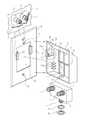
- FIG. 2shows an exploded partial assembly view of the embodiment of the invention of FIG. 1 ;
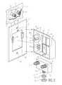
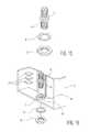
- FIG. 3shows an exploded assembly view for an embodiment of the invention
- FIG. 4shows pictorial views looking toward the back portions of a faceplate for an embodiment of the invention
- FIG. 5shows a detailed view of the back portion of a mounting dip of the wall plate for an embodiment of the invention relative to FIG. 4 ;
- FIG. 6shows a detailed view of an attachment slot located on an inside sidewall of the cover housing relative to FIG. 3 ;
- FIG. 7shows a pictorial view of the back of the cover housing with a splitter installed therein for an embodiment of the invention
- FIG. 8shows a pictorial view of the back of the faceplate with a cover housing containing a splitter secured to the front of the faceplate;
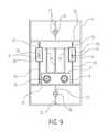
- FIG. 9is a back elevational view of the faceplate with the back of a splitter positioned therein via a cover housing secured to the front of the faceplate;
- FIG. 10is a back elevational view of a cover housing for an embodiment of the invention.
- FIG. 11is a left-side elevational view of a faceplate for an embodiment of the invention, the right side being a mirror image thereof;
- FIG. 12is a left-side devotional view of a faceplate with a cover housing containing a splitter secured thereto;
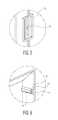
- FIG. 13shows a cross-sectional view taken along 13 - 13 of FIG. 1 , with the splitter removed, with the cover housing positioned for being slid downward upon the faceplate for locking the two together;
- FIG. 14is a cross-sectional view taken along 14 - 14 of FIG. 1 , with the splitter removed, for further showing the cover housing having been slid downward upon the front of the faceplate for locking the two together;
- FIG. 15is a pictorial view of an F-81 connector for another embodiment of the invention.
- FIG. 16is an exploded assembly view looking toward the back of cover housing for installing an F-81 connector thereon for another embodiment of the invention
- FIG. 17is a pictorial view of the completed assembly of an F-81 connector in the cover housing
- FIG. 18is a cross-sectional view taken along 13 - 13 of FIG. 1 , but further including the splitter and an added hexagonal boss 42 , for another embodiment of the invention.
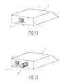
- FIG. 19is a pictorial view of cover housing with a CAT-5 Ethernet cable connector secured to a side portion of the cover housing, for another embodiment of the invention.
- FIG. 20is a pictorial view looking toward a bottom side portion of the cover housing showing the installation of an Ethernet cable connector, and an F-81 type female coaxial cable connector secured thereto, for another embodiment of the invention
- FIG. 21shows an exploded assembly view for another embodiment of the invention.
- FIG. 22is a cross-sectional view taken along 14 - 14 of FIG. 1 , with the splitter removed for showing another embodiment of the invention without a stop stud on the faceplate;
- FIG. 23is an exploded assembly view for another embodiment of the invention.
- faceplate 4is typically secured over a coaxial cable access hole 7 in a wall 5 via screws (not shown) inserted through holes 22 in the faceplate 4 and screwed into the wall 5 surrounding the wall hole 7 .
- a two-way splitter 6is secured within cover housing 2 by pushing splitter 6 into the cavity of the cover housing 2 and positioning a user output port 16 from splitter 6 to protrude from a port hole 10 of cover housing 2 .
- Output port 16is secured to cover housing 2 through use of typically a washer 17 and nut 19 , as shown.
- a signal feed-in coaxial cable 9is connected via its associated male F-type connector 13 to a female F-type input port 12 .
- a tapped-off feedback signal provided at output port 14is connected to a feedback cable 11 located in wall hole 7 via an associated F-type male coaxial cable connector 15 that mounts onto output port 14 .
- FIGS. 13 and 14show a cover housing 2 first positioned on faceplate 4 for installation thereon
- FIG. 14shows positioning for the cover plate 2 on faceplate 4 after the cover plate 2 ahs been slid downward to secure it to faceplate 4 , as previously indicated.
- FIGS. 13 and 14show a cover housing 2 first positioned on faceplate 4 for installation thereon
- FIG. 14shows positioning for the cover plate 2 on faceplate 4 after the cover plate 2 ahs been slid downward to secure it to faceplate 4 , as previously indicated.
- FIGS. 13shows a cover housing 2 first positioned on faceplate 4 for installation thereon
- FIG. 14shows positioning for the cover plate 2 on faceplate 4 after the cover plate 2 ahs been slid downward to secure it to faceplate 4 , as previously indicated.
- FIG. 1is a pictorial view of the cover housing 2 containing splitter 6 , as assembled upon a faceplate 4 , looking toward the front thereof.
- the stop tab 21is optional, for the reason that a stop function is also provided by the interaction between the attachment slots 8 of cover housing 2 and mounting clips 20 , as described below.
- FIG. 3shows an exploded assembly view of faceplate 4 , cover housing 2 , and splitter 6 , respectively.
- the faceplate 4(see FIG. 4 ) includes in this example strengthening ribs 23 , and the back portions of the mounting clips 20 .
- the cover housing 2includes strengthening ribs 32 and 34 , and interior spaced apart triangular standoffs or spacers 30 .
- FIG. 5shows a detailed pictorial view of the back portion of a mounting dip 20 , which is shown also to include tabs 36 .
- FIG. 6shows a detailed view of the construction of the attachment slot 8 .
- attachment slot 8includes a slotway 28 formed between first protruding member 26 , and a second protruding member 24 , as shown.
- FIG. 10shows a back elevational view of the cover housing 2 .
- FIG. 11shows a left-side elevational view of faceplate 4 .
- FIG. 13is a cross-sectional view for showing the installation of cover housing 2 upon faceplate 4 before locking it in place.
- FIG. 14is a cross-sectional view showing the completion of the installation of cover housing 2 on faceplate 4 , whereby the cover housing 2 has been slid downward upon the outside face of faceplate 4 for causing the opposing attachment slots 8 of cover housing 2 to engage the opposing mounting clips 20 , respectively, of faceplate 4 , thereby securing the two together.
- FIG. 10shows a back elevational view of the cover housing 2 .
- FIG. 11shows a left-side elevational view of faceplate 4 .
- FIG. 13is a cross-sectional view for showing the installation of cover housing 2
- FIGS. 1 and 8show a cover housing 2 containing a splitter 6 , with its cover housing 2 secured to a faceplate 4 , viewed from the front and back of faceplate 4 , respectively.
- cover housing 2has its downward movement on faceplate 4 limited or stopped by first protruding member 26 of attachment slot 8 striking or contacting the bottom 60 of the channel 61 of mounting clip 20 .
- the cover housing 2is configured to have an Ethernet connector 52 installed into a bottom side portion, as shown, for connection to a “CAT-5 Ethernet” cable (not shown) accessed in the hole 7 of wall 5 .
- FIG. 14is a pictorial view showing a third embodiment of the invention, whereby the cover housing 2 , rather than having a two-way splitter 6 installed therein, is configured to include the Ethernet connector 52 , in a spaced apart relation from an F-81 type female coaxial cable connector 40 , as shown protruding from a bottom edge portion of cover housing 2 , in this example.
- a modified cover housing 43includes on the interior surface of a bottom sidewall 39 protruding boss 42 having a hexagonal shaped opening 44 in association with porthole 46 , as shown. Also as shown in the exploded assembly view of FIG. 16 , the hexagonal shaped portion 44 of boss 42 is for receiving the hexagonal shaped portion 41 of an F-81 connector to permit it to be secured to the cover housing 2 via a washer 48 and nut 50 , as shown.
- the boss 42 with the hexagonal shaped portion 44ensures that the F-81 connector 41 will not turn or spin around when being secured to cover housing 2 via nut 50 .
- FIG. 18shows a splitter 6 secured within a cover housing 43 that includes a boss 42 .
- the modified cover housing 43 shown FIG. 16is otherwise substantially the same as cover housing 2 as previously described.
- the cover housing 2is modified to include two port holes 70 and 72 as shown for receiving output ports 66 and 68 , respectively, of a splitter 62 , which are each secured thereto via a washer 17 and nut 19 , as shown in this example.
- Splitter 62includes an input port 64 for connection to feed-in coaxial cable 9 via connector 13 .
- cover housing 2can be configured to secure therein other electrical connectors than those mentioned above, and other electrical or electronic devices than a two-way splitter 6 , for use in different applications.
- cover housing 2can be configured to secure therein other electrical connectors than those mentioned above, and other electrical or electronic devices than a two-way splitter 6 , for use in different applications.
Landscapes
- Coupling Device And Connection With Printed Circuit (AREA)
- Details Of Connecting Devices For Male And Female Coupling (AREA)
Abstract
Description
Claims (23)
Priority Applications (1)
| Application Number | Priority Date | Filing Date | Title |
|---|---|---|---|
| US13/593,780US8382514B1 (en) | 2012-08-24 | 2012-08-24 | Wall plate/cover housing assembly |
Applications Claiming Priority (1)
| Application Number | Priority Date | Filing Date | Title |
|---|---|---|---|
| US13/593,780US8382514B1 (en) | 2012-08-24 | 2012-08-24 | Wall plate/cover housing assembly |
Publications (1)
| Publication Number | Publication Date |
|---|---|
| US8382514B1true US8382514B1 (en) | 2013-02-26 |
Family
ID=47721120
Family Applications (1)
| Application Number | Title | Priority Date | Filing Date |
|---|---|---|---|
| US13/593,780ActiveUS8382514B1 (en) | 2012-08-24 | 2012-08-24 | Wall plate/cover housing assembly |
Country Status (1)
| Country | Link |
|---|---|
| US (1) | US8382514B1 (en) |
Cited By (4)
| Publication number | Priority date | Publication date | Assignee | Title |
|---|---|---|---|---|
| US20140224516A1 (en)* | 2013-02-08 | 2014-08-14 | Jjs Communications Co., Ltd. | Impact resistant housing for data signal devices |
| US20220006248A1 (en)* | 2020-03-04 | 2022-01-06 | Holland Electronics Llc | Uninterruptable tap |
| US11252807B2 (en)* | 2018-09-17 | 2022-02-15 | Johnson Systems Inc. | Lighting system and method thereof |
| US20230247780A1 (en)* | 2022-01-31 | 2023-08-03 | Dwellwell Analytics, Inc. | Mounting System and Method for Sensor Node |
Citations (13)
| Publication number | Priority date | Publication date | Assignee | Title |
|---|---|---|---|---|
| US4043629A (en)* | 1976-10-29 | 1977-08-23 | Db Electronics, Inc. | Radio-antenna wall plate assembly |
| US5356311A (en)* | 1993-03-25 | 1994-10-18 | Danny Liu | Network wall plate |
| US5651696A (en) | 1995-04-28 | 1997-07-29 | Jennison; Michael T. | CEBUS tap point unit |
| US5882215A (en) | 1996-07-25 | 1999-03-16 | Icg Technology, Llc | Terminating coaxial cable apparatus |
| US6793524B2 (en)* | 2001-03-30 | 2004-09-21 | Adc Telecommunications, Inc. | Multimedia outlet with protective cover |
| US6988914B2 (en) | 2003-03-14 | 2006-01-24 | Tyco Electronics Corporation | Electrical coupler with splitting receptacle jack interfaces |
| US7038561B2 (en)* | 2004-09-20 | 2006-05-02 | Robert Esty | Do-it-yourself GFI outlet kit |
| US20060099857A1 (en) | 2004-06-25 | 2006-05-11 | Ames Robert S | EZ connect, 2 way splitter |
| US7163418B2 (en)* | 2004-12-30 | 2007-01-16 | Proprietary Technologies, Inc. | Wall plate comprising signal splitting device |
| US20070275595A1 (en) | 2004-02-16 | 2007-11-29 | Serconet Ltd. | Outlet add-on module |
| US7404738B2 (en) | 2005-03-07 | 2008-07-29 | John Mezzalingua Associates, Inc. | RF signal splitter with integrated connectors |
| US7674129B1 (en)* | 2008-12-22 | 2010-03-09 | Moxa Inc. | Clamping device for DIN rail |
| US7873062B2 (en) | 2003-07-09 | 2011-01-18 | Mosaid Technologies Incorporated | Modular outlet |
- 2012
- 2012-08-24USUS13/593,780patent/US8382514B1/enactiveActive
Patent Citations (15)
| Publication number | Priority date | Publication date | Assignee | Title |
|---|---|---|---|---|
| US4043629A (en)* | 1976-10-29 | 1977-08-23 | Db Electronics, Inc. | Radio-antenna wall plate assembly |
| US5356311A (en)* | 1993-03-25 | 1994-10-18 | Danny Liu | Network wall plate |
| US5651696A (en) | 1995-04-28 | 1997-07-29 | Jennison; Michael T. | CEBUS tap point unit |
| US5882215A (en) | 1996-07-25 | 1999-03-16 | Icg Technology, Llc | Terminating coaxial cable apparatus |
| US6793524B2 (en)* | 2001-03-30 | 2004-09-21 | Adc Telecommunications, Inc. | Multimedia outlet with protective cover |
| US6988914B2 (en) | 2003-03-14 | 2006-01-24 | Tyco Electronics Corporation | Electrical coupler with splitting receptacle jack interfaces |
| US7873062B2 (en) | 2003-07-09 | 2011-01-18 | Mosaid Technologies Incorporated | Modular outlet |
| US20120028506A1 (en) | 2003-09-07 | 2012-02-02 | Mosaid Technologies Incorporated | Modular outlet |
| US20110097939A1 (en) | 2003-09-07 | 2011-04-28 | Mosaid Technologies Incorporated | Modular outlet |
| US20070275595A1 (en) | 2004-02-16 | 2007-11-29 | Serconet Ltd. | Outlet add-on module |
| US20060099857A1 (en) | 2004-06-25 | 2006-05-11 | Ames Robert S | EZ connect, 2 way splitter |
| US7038561B2 (en)* | 2004-09-20 | 2006-05-02 | Robert Esty | Do-it-yourself GFI outlet kit |
| US7163418B2 (en)* | 2004-12-30 | 2007-01-16 | Proprietary Technologies, Inc. | Wall plate comprising signal splitting device |
| US7404738B2 (en) | 2005-03-07 | 2008-07-29 | John Mezzalingua Associates, Inc. | RF signal splitter with integrated connectors |
| US7674129B1 (en)* | 2008-12-22 | 2010-03-09 | Moxa Inc. | Clamping device for DIN rail |
Cited By (6)
| Publication number | Priority date | Publication date | Assignee | Title |
|---|---|---|---|---|
| US20140224516A1 (en)* | 2013-02-08 | 2014-08-14 | Jjs Communications Co., Ltd. | Impact resistant housing for data signal devices |
| US11252807B2 (en)* | 2018-09-17 | 2022-02-15 | Johnson Systems Inc. | Lighting system and method thereof |
| US20220006248A1 (en)* | 2020-03-04 | 2022-01-06 | Holland Electronics Llc | Uninterruptable tap |
| US11611181B2 (en)* | 2020-03-04 | 2023-03-21 | Holland Electronics, Llc | Uninterruptable tap |
| US20230247780A1 (en)* | 2022-01-31 | 2023-08-03 | Dwellwell Analytics, Inc. | Mounting System and Method for Sensor Node |
| US12171072B2 (en)* | 2022-01-31 | 2024-12-17 | Dwellwell Analytics, Inc. | Mounting system and method for sensor node |
Similar Documents
| Publication | Publication Date | Title |
|---|---|---|
| US9705232B2 (en) | Encased power receptacle | |
| US8569619B2 (en) | Electrical box assembly for angled recessed mounting of high and low voltage components | |
| US7829788B2 (en) | Adapter for mounting a faceplate of a first style to an electrical outlet cavity of a second style | |
| US8404973B1 (en) | Cable entry device for high and low voltage cables | |
| US7304236B1 (en) | Electrical box assembly for recessed mounting of high and low voltage components | |
| US20110259883A1 (en) | Sectional plate for wall port incorporating reversible slide hood for wire management | |
| US8772649B1 (en) | Electrical box and frame assembly for shallow wall cavities formed by furring strips | |
| US8382514B1 (en) | Wall plate/cover housing assembly | |
| US7645935B1 (en) | Outlet assembly | |
| US4370516A (en) | Cooperative TV-FM cable splitter-ground module and housing therefor | |
| US8072779B1 (en) | Recessed electrical device housing assembly and clip | |
| US9444136B2 (en) | Configurable antenna system and method | |
| US9458998B2 (en) | Electrical fixture for transmitting and receiving data using the same component for electrical as well as structural connections | |
| US7163418B2 (en) | Wall plate comprising signal splitting device | |
| EP2541933B1 (en) | Assembly and connection device of a video door entry system monitor | |
| US9859671B2 (en) | Canopy structurally and electrically mating with a plate for attaching an electrical fixture to an electrical source | |
| US20130279105A1 (en) | Interface device and server employing same | |
| US20140184930A1 (en) | System and Method for Providing Power to a Television Accessory | |
| US9748751B1 (en) | Electrical box assembly for angled recessed mounting of high and low voltage components | |
| EP3098909B1 (en) | Push-in outlet system and method for configuring such a push-in outlet system | |
| US8476525B1 (en) | Electrical device mounting assembly for angled mounting of high and low voltage components | |
| EP3174167B1 (en) | Coaxial cable extender | |
| US20080006428A1 (en) | Side-by-side outlet | |
| JP5204081B2 (en) | Modular outlet | |
| JP2008042526A (en) | Wall terminal |
Legal Events
| Date | Code | Title | Description |
|---|---|---|---|
| AS | Assignment | Owner name:EXTREME BROADBAND ENGINEERING, LLC, NEW JERSEY Free format text:ASSIGNMENT OF ASSIGNORS INTEREST;ASSIGNORS:SHAPSON, JAY F.;SHAPSON, BRIAN J.;SHAPSON, MATTHEW M.;REEL/FRAME:029058/0894 Effective date:20120824 | |
| STCF | Information on status: patent grant | Free format text:PATENTED CASE | |
| AS | Assignment | Owner name:TIMES FIBER COMMUNICATIONS, INC., CONNECTICUT Free format text:ASSIGNMENT OF ASSIGNORS INTEREST;ASSIGNOR:EXTREME BROADBAND ENGINEERING L.L.C.;REEL/FRAME:033325/0956 Effective date:20140616 | |
| FEPP | Fee payment procedure | Free format text:PAT HOLDER NO LONGER CLAIMS SMALL ENTITY STATUS, ENTITY STATUS SET TO UNDISCOUNTED (ORIGINAL EVENT CODE: STOL); ENTITY STATUS OF PATENT OWNER: LARGE ENTITY | |
| FPAY | Fee payment | Year of fee payment:4 | |
| SULP | Surcharge for late payment | ||
| MAFP | Maintenance fee payment | Free format text:PAYMENT OF MAINTENANCE FEE, 8TH YEAR, LARGE ENTITY (ORIGINAL EVENT CODE: M1552); ENTITY STATUS OF PATENT OWNER: LARGE ENTITY Year of fee payment:8 | |
| MAFP | Maintenance fee payment | Free format text:PAYMENT OF MAINTENANCE FEE, 12TH YEAR, LARGE ENTITY (ORIGINAL EVENT CODE: M1553); ENTITY STATUS OF PATENT OWNER: LARGE ENTITY Year of fee payment:12 |