US8382136B2 - Bicycle rear suspension system linkage - Google Patents
Bicycle rear suspension system linkageDownload PDFInfo
- Publication number
- US8382136B2 US8382136B2US12/426,037US42603709AUS8382136B2US 8382136 B2US8382136 B2US 8382136B2US 42603709 AUS42603709 AUS 42603709AUS 8382136 B2US8382136 B2US 8382136B2
- Authority
- US
- United States
- Prior art keywords
- linkage member
- pivotal connection
- rear wheel
- frame portion
- bicycle
- Prior art date
- Legal status (The legal status is an assumption and is not a legal conclusion. Google has not performed a legal analysis and makes no representation as to the accuracy of the status listed.)
- Active, expires
Links
Images


Classifications
- B—PERFORMING OPERATIONS; TRANSPORTING
- B62—LAND VEHICLES FOR TRAVELLING OTHERWISE THAN ON RAILS
- B62K—CYCLES; CYCLE FRAMES; CYCLE STEERING DEVICES; RIDER-OPERATED TERMINAL CONTROLS SPECIALLY ADAPTED FOR CYCLES; CYCLE AXLE SUSPENSIONS; CYCLE SIDE-CARS, FORECARS, OR THE LIKE
- B62K19/00—Cycle frames
- B62K19/18—Joints between frame members
- B—PERFORMING OPERATIONS; TRANSPORTING
- B62—LAND VEHICLES FOR TRAVELLING OTHERWISE THAN ON RAILS
- B62K—CYCLES; CYCLE FRAMES; CYCLE STEERING DEVICES; RIDER-OPERATED TERMINAL CONTROLS SPECIALLY ADAPTED FOR CYCLES; CYCLE AXLE SUSPENSIONS; CYCLE SIDE-CARS, FORECARS, OR THE LIKE
- B62K25/00—Axle suspensions
- B62K25/04—Axle suspensions for mounting axles resiliently on cycle frame or fork
- B62K25/28—Axle suspensions for mounting axles resiliently on cycle frame or fork with pivoted chain-stay
- B62K25/286—Axle suspensions for mounting axles resiliently on cycle frame or fork with pivoted chain-stay the shock absorber being connected to the chain-stay via a linkage mechanism
Definitions
- the present inventionrelates to a new bicycle rear suspension system, and in particular to a four-bar suspension system that offers improved pedaling and bump absorption performance by means of controlling the rate of chainstay lengthening through the use of a small eccentric mechanism located in close proximity to the bicycle chain line.
- a suspension systemallows the rear wheel of the bike to better track the terrain resulting in improved traction while pedaling, turning, and braking. Additionally, the absorption of bump forces by the suspension system increases rider comfort. These systems range from the simple to the complex.
- One of the simplest bicycle suspensionsis the single pivot system in which a rear triangle swingarm is attached to a main front triangle at a single pivot point. With this type of suspension, the rear wheel of the bike may track the terrain but must do so while moving in a simple circular arc about the pivotal connection.
- the single pivot systemsare very simple, relatively easy to design, and adequately handle small bumps, they fail to address many performance issues. Both their pedaling performance and their bump absorption capabilities are controlled by the location of the single pivotal connection between the front triangle and the rear triangle swingarm.
- the rear axle of the bikerotates about a single axis, and as a consequence the bike's rear suspension is either compressed or extended by the forces imparted to the pedals by the bike rider, dependent upon the specific configuration of the bike suspension.
- compression and extension of the suspensioncan impart torque on the pedals and supply unwanted force to the rider's legs.
- some of the energy expended by the rider of the bikeis used needlessly wasted, either compressing or extending the suspension of the system, or resisting unwanted pedal rotation imparted by the suspension.
- the chainstay length of a bicycleis the distance from the rear wheel axle to the center of the bottom bracket shell.
- the chainstay length of a bicycle with real wheel suspensionmay be variable, the length being dictated by the location of the pivotal connection between the front triangle and the rear triangle swingarm and the motion of the rear triangle swingarm.
- the rate of chainstay lengtheningis high, so as to decrease unwanted pedal rotation and increase the anti-squat characteristics of the suspension system, the result will be excessive chainstay lengthening at full compression and the application of excessive torque to the pedal crankarms.
- a more complex form of bicycle suspensionis a linkage system.
- Such systemsattach the rear wheel swingarm to the main front triangle through a plurality of links to improve the performance of the suspension system by manipulating both shock rate and wheel travel path, and thus chain stay lengthening.
- These systemsprovide challenges to the suspension designer, in that there is typically a tradeoff between optimally manipulating the rear wheel travel path and controlling the change in the shock rate.
- the variation in the rear wheel travel pathhas typically been small throughout the range of travel. Systems that vary the rear wheel travel path to a greater extent generally must also vary the shock rate to a great extent, which leads to undesirable bump absorption characteristics.
- linkage systemshave been developed in an attempt to resolve the above limitations.
- Some linkage systemsuse a single pivot swingarm and a linkage to activate the shock absorber, such as the Turner 5-Spot by Turner Suspension Bicycles, Inc. in Murrieta, Calif.
- These systemsallow for more complicated leverage ratios than a single pivot system, which results in increased tunability of the shock absorber leverage rate.
- the rear wheelstill moves in an arc, resulting in many of the same compromises in performance from which the single pivot suspension systems suffer.
- the first classcomprises systems that use a long first linkage member that places a pivot point near the rear axle.
- the long link systemsgenerally have separate chainstay and seat stay assemblies that are bolted together at a pivot.
- An example of a long link four-bar linkage systemis the Stumpjumper by Specialized Bicycle Components out of Morgan Hill, Calif., and disclosed in U.S. Pat. No. 5,899,480 to Leitner.
- this class of four bar linkage systemsarticulates the rear wheel in a large radius arc
- the employment of an optimal amount of chainstay lengthening in the early part of the rear wheel's travelresults in an unacceptable total amount of chainstay lengthening when the system is fully compressed.
- this style of suspension systemtypically employs the minimal amount of chainstay lengthening that is acceptable, so as to consequently minimize the total amount of lengthening when the system is fully compressed.
- Firmer shock absorber spring and damping ratesare required to allow for acceptable pedaling performance.
- the second class of four-bar linkage systemsuses a short first linkage member where the connection between the seat stays and the chainstays is generally rigid, thereby resulting in a rear triangle wherein a swingarm is connected to two short links. Due to the short linkage members rotating with greater angular velocity when compared to the first type of four bar linkage system there is greater ability to tune the axle path of this suspension system.
- the short link designs making up the second class of four-bar linkage systemscan be further separated into two sub-classes.
- the first sub-classis one in which the two links rotate in the same direction as the suspension is compressed.
- U.S. Pat. No. 7,128,329 to Weaglediscloses a rear wheel suspension system that falls into this first class of short link four bar linkage systems.
- This designutilizes anti-squat behavior to mitigate the unwanted effects of the suspension system compressing and extending due to forward acceleration when pedaling.
- This designsuffers from the drawback that chainstay lengthening effects are minimally utilized and instead the suspension system is designed to provide an optimized anti-squat behavior for an arbitrary constant pedaling input force and gear. In practice, both the pedaling input force and gear are greatly variable and thus an assumption that they are an arbitrary constant is invalid and suboptimal.
- the Rockrider by Decathlon out of Villeneuve d'Ascq, Franceis an example of a bicycle of the first sub-class that uses an eccentric as a link in a short link four bar linkage system.
- the eccentricrotates in one direction as the suspension compresses and in the opposite direction as the suspension extends.
- the distance between the pivots on the small linkis significantly larger than 15 mm, and thus suffers from a weight disadvantage.
- This designmoves the rear wheel in a very large arc, and as such suffers from the typical performance drawbacks experienced by other similar systems, such as the inability to control the chainstay lengthening effect and provide for an optimized rear wheel travel path that reduces pedaling induced compression and extension of the suspension.
- the linksrotate in opposite directions as the system is compressed. That is, one link rotates in a first direction and a second link rotates in a second direction.
- An example of the second type of short link systemis the Blur by Santa Cruz Bicycles out of Santa Cruz, Calif. and disclosed in U.S. Pat. No. 6,206,397 to Klassen and Calon. These systems employ an S-shaped wheel travel path to selectively apply chainstay lengthening. The net result, however, is that as the suspension moves from its statically loaded sag point (to either a direction of further compression or a direction of reduced compression), chainstay lengthening occurs. Because chainstay lengthening occurs during extension from the suspension's statically loaded sag point, the suspension if prevented from utilizing negative travel to allow the wheel to follow drops in the terrain and thus maintain traction.
- U.S. Pat. No. 6,099,010 to Busbydiscloses a bicycle having an independent equilibrium sensing suspension system for its crank assembly.
- This systemis essentially a four bar system in which the pedal crank arm is connected to the first linkage member instead of to the front triangle.
- This systemallows for greater rearward motion of the rear wheel without a corresponding increase in chainstay lengthening. This is accomplished by the rearward motion of the entire pedal crank assembly when the suspension is compressed.
- this motion of the pedal crank axis relative to the seat of the bicycleis perceptible to the rider, and also affects pedaling performance as the relationship between the seat and the pedals changes as the suspension is compressed.
- It is a further object of the invention to provide a short link suspension systemcomprising a link that changes its direction of rotation as the system is compressed, and more specifically comprising a short link that rotates in a first direction and then in the opposite direction as the suspension system is compressed.
- the present inventionis a bicycle suspension system comprising a bicycle main frame and rear wheel triangle.
- the main framepreferably comprises a head tube for a steering apparatus, a seat tube, a down tube, a top tube, and a bottom bracket for a pedal/drive apparatus, a connection to a front end of a shock absorber, a connection to a first linkage member, and a connection to a second linkage member.
- the rear wheel trianglefurther comprises a pair of seat stays with a first end connecting to a rear drop-out and a second end connecting to seat stay ends, a pair of chainstays with a first end connecting to a rear drop-out and a second end connecting to a chainstay yoke, a pair of rear drop-outs to hold the rear wheel, a chainstay yoke providing a mechanical connection to the first linkage member, and seat stay ends providing a mechanical connection to the second linkage member.
- the first linkage memberis preferably one of an eccentric or an off center axle, although other small links may be utilized as are known in the art.
- the main frame and rear wheel triangle of the bicycleallow for the attachment of conventional bicycle components such as handlebars, a seat, the drivetrain and brakes in a standard configuration.
- the rear wheel trianglealso has attachment points to linkage members in specific locations that contribute to controlling the motion of the rear wheel axle.
- the first linkage member (and, in a preferred embodiment, the lower and shorter of the links) and the second linkcontribute to controlling the motion of the rear wheel axle.
- the first linkage memberwhen viewed from the drivetrain side of the bike rotates counterclockwise to add chainstay lengthening in the beginning of the travel of the suspension system, and then reverses rotational direction to rotate clockwise near the end of the travel of the suspension system.
- Alternative embodiments of the inventionmay have different rotation characteristics to achieve the same effect.
- the first linkage member's proximity to the drivetrain chain line of the bicycleallows the first linkage member's small length to have a significant effect on chainstay lengthening.
- the second linkage memberin addition to contributing to controlling the rear axle motion, in a preferred embodiment also allows for the attachment of the shock absorber, and its configuration controls the ratio of the shock absorber compression relative to the rear wheel compression.
- FIG. 1is a graph showing chainstay lengthening (i.e. the derivative of chainstay length with respect to vertical wheel travel (“dCSL”)) vs. vertical wheel travel (“VWT”) for both a preferred embodiment of the present invention (curved line) and for a prior art single pivot suspension system (straight line) in which the main pivot location for both systems is identical;
- chainstay lengtheningi.e. the derivative of chainstay length with respect to vertical wheel travel (“dCSL”)
- VWTvertical wheel travel
- FIG. 2is a graph showing chainstay length with respect to vertical wheel travel for a preferred embodiment of the present invention
- FIG. 3depicts a right side view of the present invention to illustrate the components of the system in a preferred embodiment
- FIG. 4depicts a detailed perspective view of the first link and surrounding components of preferred embodiment
- FIG. 5depicts a detailed perspective view of the second link of the preferred embodiment
- FIG. 6depicts a perspective view of the preferred embodiment.
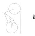
- FIG. 7is a simplified schematic of the preferred embodiment of the present invention wherein the suspension is fully extended
- FIG. 8is a simplified schematic of the preferred embodiment the present invention wherein the suspension in a state midway between full extension and full compression;
- FIG. 9is a simplified schematic of the preferred embodiment the present invention wherein the suspension is fully compressed
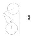
- FIG. 10is a simplified schematic of an alternative embodiment of a rear wheel suspension system of a bicycle according to the present invention wherein the suspension is fully extended;
- FIG. 11is a simplified schematic of the alternative embodiment wherein the suspension is in a state midway between full extension and full compression;
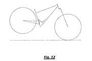
- FIG. 12is a simplified schematic of the alternative embodiment wherein the suspension is fully compressed
- FIG. 13is a graph showing shock rate with respect to VWT for a preferred embodiment of the present invention.
- FIG. 14is a graph showing the rate of change of shock rate with respect to VWT
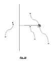
- FIG. 15is a diagrammatic example showing an imaginary plane through a rear wheel axis and perpendicular to a line through the rear wheel axis and the main pivot of a first link, wherein the suspension is in a first, or fully extended configuration;
- FIG. 16is a diagrammatic example showing an imaginary plane through a rear wheel axis and perpendicular to a line through the rear wheel axis and the main pivot of a first link, wherein the suspension is in a second configuration;
- FIG. 17is a diagrammatic example showing an imaginary plane through a rear wheel axis and perpendicular to a line through the rear wheel axis and the main pivot of a first link, wherein the suspension is in a third configuration;
- FIG. 18is a diagrammatic example showing an imaginary plane through a rear wheel axis and perpendicular to a line through the rear wheel axis and the main pivot of a first link, wherein the suspension is in a fourth configuration;
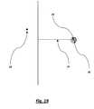
- FIG. 19is a diagrammatic example showing an imaginary plane through a rear wheel axis and perpendicular to a line through the rear wheel axis and the main pivot of a first link, wherein the suspension is in a fifth, or fully compressed configuration.
- Chainstay length(CSL)
- dCSLchainstay lengthening
- the Applicant's suspension systemhas a high dCSL in the beginning portion of the suspension's travel, and then a rapid decrease in dCSL in a later portion of the suspension's travel.
- the overall chainstay length increaseis relatively small, yet many performance and comfort benefits are still derived.
- FIG. 1depicts a plot of the derivative of the chainstay length (dCSL) (i.e. the rate of change of chainstay lengthening) with respect to vertical wheel travel (“VWT”) vs. vertical wheel travel.
- VWTvertical wheel travel
- FIG. 2simpler, just depicts CSL vs. VWT.
- Curved plotline 1is representative data of the preferred embodiment of the present invention. As should be readily apparent, the rate is much higher at the beginning stages of the suspension compression, where VWT is relatively small. As VWT increases, the dCSL decreases.
- straight plot line 2is data for the same vertical wheel travel distances measured in a representative single pivot suspension system with the main pivot located in the same position relative to the bottom bracket and drivetrain path as in the preferred embodiment of the present invention.
- a first point 3exists where the second derivative of CSL (i.e. the rate of change of chainstay lengthening) with respect to vertical wheel travel is equal to the constant value of the second derivative of the chainstay length of a representative single pivot suspension system with the main pivot location at the same location of the present invention.
- the varying rate of CSL described aboveis accomplished through a linkage system comprising a very small link located in close proximity to the bicycle's chain drive force line.
- the small linkchanges its direction of rotation through the course of the suspension compressing, as will be described in further detail below.
- FIG. 3a right side view of the preferred embodiment of the present invention is depicted.
- the systemcomprises a rear wheel swingarm 7 connected to a main front triangle 5 , by the means of a first linkage member 6 , and a second linkage member 8 .
- the front triangle 5further comprises a seat tube 9 , and a down tube 10 , both of which are attached to a bottom bracket 11 that houses a pedal assembly (not shown), and a head tube 12 , which serves as a steering axis for a front wheel (not shown) and to which is attached a top tube 13 .
- down tube 10comprises a connection for a front triangle forward shock mount 16 for a shock absorber (not shown in this figure, see FIG. 6 ).
- the rear wheel swingarm 7includes a pair of seat stays 17 and a pair of chainstays 18 that are joined to each other creating an acute angle at their rearward ends proximate a rear wheel axle 19 (rear wheel not shown) at a pair of rear wheel dropouts 20 .
- a single upright structure 21is engaged between the pair of chainstays 18 and the pair of seat stays 17 to provide a rigid triangular structure for swingarm 7 . See FIGS. 3 and 6 .
- a chainstay yoke 22is joined to the forward end of chainstays 18 , and houses a chainstay pivotal connection 23 to the first linkage member 6 .
- a pair of seat stay ends 24is joined to the forward end of seat stays 17 and house a seat stay pivotal connection 25 to the second linkage member 8 .
- the distance between the chainstay pivotal connection 23 and rear wheel axle 19is approximately 442 mm, but this distance can be accomplished by various combinations of lengths of rear drop-out 20 , chainstays 18 , and chainstay yoke 22 .
- the distance between the seat stay pivotal connection 25 and the rear wheel axle 19 in the exemplary embodimentis approximately 463 mm.
- the distance between chainstay pivotal connection 23 and seat stay pivotal connection 25 in the exemplary embodimentis approximately 169 mm.
- bearingsare utilized to provide the means of pivotal connection, however, it should be clear to one skilled in the art that a pivotal connection other than bearings, such as a bushing or other structure, could be utilized for either pivotal connection, and that lengths of various members could be adjusted to accommodate various configurations without changing the scope of the present invention.
- first linkage member 6in the preferred embodiment is an eccentric mechanism in which first linkage pivotal connection 14 is achieved by a bearing assembly that in the exemplary embodiment is approximately 35 mm in inner diameter.
- first linkage pivotal connection 14is achieved by a bearing assembly that in the exemplary embodiment is approximately 35 mm in inner diameter.
- Other structures which accomplish the same eccentric pivoting action, such as an off center axle or the likemay be used without departing from the scope of the invention.
- Chainstay pivotal connection 23utilizes a smaller cartridge bearing assembly housed within the chainstay yoke 22 (not shown in FIG.
- first linkage pivotal connection 14is approximately 49 mm above the pedal axis of the bottom bracket 11 and 29 mm behind the pedal axis of said bottom bracket 11 . It should be clear to one skilled in the art that a pivotal connection other than a bearing assembly could be utilized for the first linkage pivotal connection 14 and the chainstay pivotal connection 23 .
- chainstay pivotal connection 23may be contained within either the first linkage member 6 or the rear wheel swingarm 7 , and the distance between the first linkage pivotal connection 14 and the chainstay pivotal connection 23 as well as the location of first linkage pivotal connection 14 relative to the bottom bracket 11 may be adjusted to accommodate various configurations without changing the scope of the present invention.
- FIG. 5illustrates a detailed view of second linkage member 8 , second linkage pivotal connection 15 at one end, and seat stay pivotal connection 25 at the other end, the distance between the two pivotal connections in the exemplary embodiment is approximately 71.5 mm.
- the second linkage member 8further comprises a shock absorber pivotal connection 27 to which a shock absorber (not shown in FIG. 5 ) may be attached.
- the shock absorber pivotal connection 27is approximately 15 mm from the seat stay pivotal connection 25 and 80.5 mm from the second linkage pivotal connection 15 .
- second linkage pivotal connection 15is located approximately 154 mm above the bottom bracket pedal axis 11 and 17 mm behind the bottom bracket pedal axis 11 .
- FIG. 6is a perspective view of the preferred embodiment of the invention that illustrates a representative shock absorber 30 pivotally engaged between a front triangle forward shock mount 16 and the shock absorber pivotal connection 27 . As the rear wheel is articulated generally upwards, the shock absorber is compressed in length between the two mounting points providing resistance to the rear wheel's motion.
- FIGS. 7-9depict schematics of the preferred embodiment of the invention wherein the rear wheel suspension is at varying stages of compression.
- FIG. 7shows the suspension system in its fully extended (uncompressed) state while
- FIG. 9shows the suspension system in its fully compressed state.
- FIG. 8shows the suspension system in a state between full extension and full compression.
- FIGS. 10-12depict schematics of a variation of the preferred embodiment where the connection between the second linkage member and the main frame is above the connection between the second linkage member and the rear triangle at varying stages of compression of the rear wheel suspension system.
- FIG. 10shows the suspension system in its fully extended (uncompressed) state while FIG. 12 shows the suspension system in its fully compressed state.
- FIG. 11shows the suspension system in a state between full extension and full compression.
- the bicycle main framegenerally includes a seat tube and a down tube, both of which are attached to a bottom bracket that houses a pedal assembly, a top tube, together with the down tube attached to the head tube, and a front fork.
- a first location above the bottom bracket pedal axis and proximate to the bicycle chain drive force line for the pivotal connection to the first linkage member of the rear wheel suspension systemand a second location above the first location for the pivotal connection to the second linkage member.
- the rear wheel suspension systemgenerally includes a first linkage member, a rear wheel swingarm, and a second linkage member.
- the first linkage member of the variation of the preferred embodimentis an eccentric mechanism in which a bearing assembly of approximately 35 mm in inner diameter accomplishes the pivotal connection between the first linkage member and the rear triangle.
- the pivotal connection between the first linkage member and the rear triangleutilizes a smaller bearing assembly housed within the chainstay yoke of the rear triangle, and a axle that is bolted through a shaft offset within the first linkage member a distance of approximately 13 mm from the center of the main pivotal connection between the first linkage member and the main frame.
- the main pivot location between the first linkage member and the main frameis approximately 66 mm above the pedal axis of the bottom bracket and 27 mm behind the bottom bracket.
- bearing assembliesare described and are the preferred means for creating the pivotal connections, other means well known in the art could be used.
- the pivotal connection to the rear trianglemay be contained within either the first linkage member or the rear triangle, and the distance between the pivotal connections of the first linkage member as well as the first linkage pivotal connection location relative to the bottom bracket could be adjusted to accommodate various configurations without changing the scope of the present invention.
- the rear wheel swingarmincludes a pair of seat stays and a pair of chainstays that are joined to each other at their rearward ends proximate to the axle of the rear wheel at a pair of rear wheel drop-outs.
- An upright structureis engaged between the chainstays and the seat stays to provide a rigid triangular structure for the swingarm.
- a chainstay yokeis joined to the forward end of the chainstays and houses a pivotal connection to the first linkage member.
- Seat stay endsare joined to the forward end of the seat stays and house a pivotal connection to the second linkage member.
- the distance between the chainstay pivot and the rear axle of the alternative embodimentis approximately 419 mm, and said length can be accomplished by various combinations of lengths of rear drop-out, chainstays, and chainstay yoke.
- the distance from the seat stay pivotal connection between the rear triangle and the second linkage member of the preferred embodiment to the rear wheel axleis approximately 420 mm.
- the distance from the pivotal connection between the rear triangle and the first linkage member to the pivotal connection between the rear triangle and second linkage members of the preferred embodimentis approximately 80 mm.
- the second linkage memberhas a pivotal connection to the rear triangle at one end, and a pivotal connection to the main frame on the other end.
- the distance between the seat stay pivotal connection and the second linkage pivotal connection in the exemplary embodiment of the alternative embodiment of the inventionis approximately 53 mm.
- the pivotal connection between the second linkage member and the main frame of the bicycleis located approximately 12 mm above the bottom bracket and 37 mm behind the bottom bracket.
- the second linkage memberadditionally contains a pivotal connection to provide for the attachment of a bicycle shock absorber.
- This pivotal connectionis approximately 36 mm from the seat stay pivotal connection between the second linkage member and the rear triangle and 45 mm from the second linkage pivotal connection between the second linkage member and the front triangle.
- FIG. 13depicts a plot of shock rate vs. vertical wheel travel. This figure illustrates the relatively small overall change in shock rate in the Applicant's system, and specifically that the slope of the curve is first negative, then positive, then negative again.
- FIG. 14depicts a plot of the derivative of shock rate with respect to vertical wheel travel (‘d Shock Rate’) vs. vertical wheel travel.
- This figurefurther illustrates the change in shock rate by confirming that at the points where the shock rate is inflected from a negative slope to a positive slope and from a positive slope to a negative slope the derivative of the shock rate is zero. It should be apparent from this figure that the derivative shock rate curve is zero at two points indicating a change in sign of the shock rate.
- FIG. 15-19depict a simplified schematic of the first linkage member, including a first pivotal connection 29 to the main front triangle and a second pivotal connection 30 to the rear wheel swingarm forward of the first pivotal connection, a rear wheel axle 28 , and a vertical plane relative to the ground (not labeled with a reference number) when the suspension system is fully extended and additionally some distance 31 behind the first linkage member.
- These figuresillustrate the motion of the second pivotal connection 30 of the first linkage member relative to the vertical plane as the suspension system is compressed.
- FIG. 15depicts the system in its fully compressed state.
- FIG. 16-18show the system in increasing states of compression
- FIG. 19shows the system in its fully compressed state.
- the second pivotal connection 30 of the first linkage memberfirst moves closer to the vertical plane by rotating counter-clockwise and then moves away from the vertical plane by rotating clockwise.
- the bike and suspensionmay be said to comprise a front triangle and rear wheel having a rear wheel axis, and a rear wheel suspension system.
- the rear wheel suspension systemcomprises a link further comprising a first pivotal axis for connection to the front triangle and a second pivotal axis for connection to a rear wheel swingarm.
- the distance from the second pivotal axis to some arbitrary vertical planecan be said to decrease during a first portion of the suspension compression and increase from the arbitrary vertical plane during the second portion of suspension compression, wherein as the suspension changes configuration from fully extended to fully compressed, it moves through, in order, the first portion and second portion of compression.
- the arbitrary vertical plane in this descriptionis defined as some plane perpendicular to the ground when the suspension is fully extended, and located some distance behind said link.
Landscapes
- Engineering & Computer Science (AREA)
- Mechanical Engineering (AREA)
- Axle Suspensions And Sidecars For Cycles (AREA)
Abstract
Description
Claims (24)
Priority Applications (3)
| Application Number | Priority Date | Filing Date | Title |
|---|---|---|---|
| US12/426,037US8382136B2 (en) | 2008-04-17 | 2009-04-17 | Bicycle rear suspension system linkage |
| PCT/US2010/031640WO2010121267A1 (en) | 2009-04-17 | 2010-04-19 | Improved bicycle rear suspension system |
| EP10765349AEP2419320A1 (en) | 2009-04-17 | 2010-04-19 | Improved bicycle rear suspension system |
Applications Claiming Priority (2)
| Application Number | Priority Date | Filing Date | Title |
|---|---|---|---|
| US12478908P | 2008-04-17 | 2008-04-17 | |
| US12/426,037US8382136B2 (en) | 2008-04-17 | 2009-04-17 | Bicycle rear suspension system linkage |
Publications (2)
| Publication Number | Publication Date |
|---|---|
| US20090261556A1 US20090261556A1 (en) | 2009-10-22 |
| US8382136B2true US8382136B2 (en) | 2013-02-26 |
Family
ID=56291114
Family Applications (1)
| Application Number | Title | Priority Date | Filing Date |
|---|---|---|---|
| US12/426,037Active2031-02-15US8382136B2 (en) | 2008-04-17 | 2009-04-17 | Bicycle rear suspension system linkage |
Country Status (1)
| Country | Link |
|---|---|
| US (1) | US8382136B2 (en) |
Cited By (28)
| Publication number | Priority date | Publication date | Assignee | Title |
|---|---|---|---|---|
| US20130093160A1 (en)* | 2011-10-12 | 2013-04-18 | Edward Alsop | Adjustable Geometry Bicycle Rear Wheel Suspension System |
| US8998235B2 (en) | 2012-03-23 | 2015-04-07 | Level One Engineering Llc | Bicycle rear suspension system |
| US20150115569A1 (en)* | 2012-06-23 | 2015-04-30 | Bicycle Fabrications Llc | Bicycle rear suspension with a two axis wheel path |
| US9156521B2 (en) | 2013-12-23 | 2015-10-13 | Wayne Lumpkin | Bicycle frame rear suspension with flexing frame segment |
| US9962597B2 (en) | 2016-10-11 | 2018-05-08 | Future Motion, Inc. | Suspension system for one-wheeled vehicle |
| US10010784B1 (en) | 2017-12-05 | 2018-07-03 | Future Motion, Inc. | Suspension systems for one-wheeled vehicles |
| US20180370589A1 (en)* | 2017-06-21 | 2018-12-27 | Andrea Pedretti | Bicycle frame |
| US10293881B2 (en) | 2004-09-15 | 2019-05-21 | Yeti Cycling, Llc | Rear suspension system for a bicycle |
| US10343742B2 (en) | 2010-08-20 | 2019-07-09 | Yeti Cycling, Llc | Link suspension system |
| US10457349B2 (en) | 2017-03-23 | 2019-10-29 | Darrell W. Voss | Vehicle component |
| US10457348B2 (en)* | 2013-03-15 | 2019-10-29 | USUL Corporation | Bicycle rear suspension |
| US10618595B2 (en) | 2017-03-23 | 2020-04-14 | Darrell W Voss | Vehicle |
| US10723410B2 (en) | 2017-03-23 | 2020-07-28 | Darrell W Voss | Vehicle |
| US10766563B2 (en) | 2013-01-16 | 2020-09-08 | Yeti Cyclying, Llc | Rail suspension with integral shock and dampening mechanism |
| US10822048B2 (en) | 2010-08-20 | 2020-11-03 | Yeti Cycling, Llc | Reciprocating rail movement suspension system |
| US10870461B2 (en) | 2017-03-23 | 2020-12-22 | Darrell W. Voss | Vehicle component |
| US10926830B2 (en) | 2017-07-07 | 2021-02-23 | Yeti Cycling, Llc | Vehicle suspension linkage |
| US11173983B2 (en) | 2017-03-17 | 2021-11-16 | Yeti Cycling, Llc | Vehicle suspension linkage |
| US11273364B1 (en) | 2021-06-30 | 2022-03-15 | Future Motion, Inc. | Self-stabilizing skateboard |
| US11299059B1 (en) | 2021-10-20 | 2022-04-12 | Future Motion, Inc. | Self-stabilizing skateboard |
| US11548587B2 (en) | 2017-03-23 | 2023-01-10 | Darrell W Voss | Vehicle |
| US11890528B1 (en) | 2022-11-17 | 2024-02-06 | Future Motion, Inc. | Concave side rails for one-wheeled vehicles |
| US12005340B2 (en) | 2020-10-06 | 2024-06-11 | Future Motion, Inc. | Suspension systems for an electric skateboard |
| US12077241B2 (en) | 2019-02-01 | 2024-09-03 | Yeti Cycling, Llc | Multi-body vehicle suspension linkage |
| US12145684B2 (en) | 2019-12-24 | 2024-11-19 | Yeti Cycling, Llc | Constrained multiple instantaneous velocity center linkage assembly for vehicle suspension |
| US12187373B1 (en) | 2024-02-29 | 2025-01-07 | Future Motion, Inc. | Skateboard footpads having foot engagement structures and traction inserts |
| US12384484B2 (en) | 2020-11-18 | 2025-08-12 | Yeti Cycling, Llc | Integrated motor mount and suspension pivot |
| EP4624202A1 (en)* | 2024-03-25 | 2025-10-01 | Enrico Ciampelli | Suspension for vehicles with one or more wheels, vehicle comprising this suspension and method for making this suspension |
Families Citing this family (7)
| Publication number | Priority date | Publication date | Assignee | Title |
|---|---|---|---|---|
| US7837213B2 (en)* | 2007-04-16 | 2010-11-23 | Trek Bicycle Corporation | Bicycle rear wheel suspension system |
| US8066297B2 (en)* | 2009-07-21 | 2011-11-29 | Sotto, Llc | Bicycle rear suspension linkage |
| US9216791B2 (en) | 2011-03-14 | 2015-12-22 | Christopher Hudec | Bicycle suspension system |
| WO2012122634A1 (en) | 2011-03-14 | 2012-09-20 | Cmh Plus Holdings Ltd. | Bicycle suspension system |
| SK6148Y1 (en) | 2011-08-22 | 2012-06-04 | Boris Hudak | Bike with modifiable design to climb, descent and terrain roughness |
| EP3287354B1 (en)* | 2016-08-24 | 2020-07-29 | Jochen Klieber | Spring-loaded bicycle frame |
| EP3917822A4 (en)* | 2019-02-01 | 2022-11-02 | Yeti Cycling, LLC | MULTIPLE VEHICLE SUSPENSION |
Citations (39)
| Publication number | Priority date | Publication date | Assignee | Title |
|---|---|---|---|---|
| US5553881A (en) | 1995-01-25 | 1996-09-10 | Outland Design Technologies, Inc. | Bicycle rear suspension system |
| US5628524A (en)* | 1995-01-25 | 1997-05-13 | Outland Design Techologies, Inc. | Bicycle wheel travel path for selectively applying chainstay lengthening effect and apparatus for providing same |
| US5791674A (en) | 1997-03-13 | 1998-08-11 | Cannondale Corporation | Bicycle suspension system |
| WO1998049046A1 (en) | 1997-04-25 | 1998-11-05 | Renault Sport | Bicycle rear suspension |
| US6076845A (en)* | 1998-09-24 | 2000-06-20 | Schwinn Cycling & Fitness Inc. | Rear suspension for a bicycle having a flexible chain stay |
| EP0728094B1 (en) | 1994-09-09 | 2000-06-28 | Rockshox, Inc. | Rear wheel suspension for a bicycle and bicycle equipped therewith |
| US6131934A (en) | 1998-12-18 | 2000-10-17 | Sinclair; Christopher Jeffery | Bicycle rear suspension system |
| US6203042B1 (en) | 1998-02-20 | 2001-03-20 | Trek Bicycle Corporation | Bicycle rear suspension system providing relative rearward motion of rear axle |
| US6206397B1 (en) | 1995-01-25 | 2001-03-27 | James B. Klassen | Bicycle wheel travel path for selectively applying chainstay lengthening effect and apparatus for providing same |
| US20010015540A1 (en) | 1996-03-15 | 2001-08-23 | Lawwill Merton R. | Rear suspension for a bicycle |
| US6308975B1 (en) | 1998-02-26 | 2001-10-30 | Moulton Developments Limited | Bicycle and a rear wheel suspension therefor |
| US20030038450A1 (en) | 2001-08-22 | 2003-02-27 | Duhane Lam | Rear suspension system for two-wheeled vehicles, particularly bicycles |
| US20030132603A1 (en) | 1997-06-10 | 2003-07-17 | Groupe Procycle Inc./Procycle Group Inc. | Bicycle rear suspension |
| US6712373B2 (en) | 2002-04-15 | 2004-03-30 | Specialized Bicycle Components, Inc. | Bicycle rear suspension |
| US6712374B2 (en) | 2001-07-26 | 2004-03-30 | Promiles | Two-wheeled vehicle with rear suspension |
| US20050057018A1 (en)* | 2003-09-15 | 2005-03-17 | Saiki Neal Tate | Bicycle rear suspension system |
| US6880847B2 (en) | 2003-05-27 | 2005-04-19 | Specialized Bicycle Components, Inc. | Bicycle rear suspension |
| US6886846B2 (en) | 2002-09-06 | 2005-05-03 | Ryan Michael Carroll | Rear bicycle suspension |
| US20050156402A1 (en) | 2002-09-06 | 2005-07-21 | Carroll Ryan M. | Rear bicycle suspension |
| US6969081B2 (en) | 2001-11-01 | 2005-11-29 | Atb Sales Limited | Bicycle rear suspension |
| US20050285367A1 (en)* | 2004-06-29 | 2005-12-29 | Owen Chang | Bicycle rear suspension system |
| US20060022429A1 (en)* | 1998-03-02 | 2006-02-02 | Anthony S. Ellsworth | Bicycle suspension apparatus and related method |
| WO2006032052A2 (en) | 2004-09-15 | 2006-03-23 | Yeti Cycling, Llc | Rear suspension system for a bicycle |
| US7048292B2 (en)* | 2003-09-25 | 2006-05-23 | David Weagle | Bicycle suspension systems |
| US7066481B1 (en) | 2005-04-13 | 2006-06-27 | Felt Racing, Llc | Bicycle rear suspension |
| USRE39159E1 (en)* | 1995-01-25 | 2006-07-11 | Santa Cruz Bicycles, Inc. | Bicycle wheel travel path for selectively applying chainstay lengthening effect and apparatus for providing same |
| US20060181053A1 (en)* | 2004-06-29 | 2006-08-17 | Giant Manufacturing Co., Ltd. | Bicycle suspension system |
| JP3853808B2 (en) | 2004-07-13 | 2006-12-06 | 巨大機械工業股▲分▼有限公司 | Bicycle with rear wheel suspension |
| US7216883B2 (en) | 2005-03-02 | 2007-05-15 | Rocky Mountain Bicycles-A Division Of Procycle Group Inc. | Bicycle with rear suspension |
| US20070108725A1 (en)* | 2005-11-14 | 2007-05-17 | Santa Cruz Bicycles, Inc. | Bicycle rear wheel suspension system with controlled variable shock rate |
| DE19802429B4 (en) | 1998-01-23 | 2007-07-26 | Storck, Markus | Rear suspension for bicycles |
| EP1669282B1 (en) | 2003-10-01 | 2007-08-22 | Orbea, S. Coop. Ltda. | Bicycle rear suspension |
| WO2007104795A1 (en) | 2006-03-15 | 2007-09-20 | Cycles Lapierre | Bicycle rear suspension |
| US20070246909A1 (en)* | 2006-04-20 | 2007-10-25 | Ming-Chien Weng | Bicycle frame |
| US20080054595A1 (en)* | 2006-09-01 | 2008-03-06 | Lu Daniel T F | Bicycle frame with a counter-rotating four bar linkage system |
| US20080258427A1 (en) | 2003-12-12 | 2008-10-23 | Noel Buckley | Rear suspension system for bicycles |
| US20080303242A1 (en) | 2007-06-07 | 2008-12-11 | O'connor D Arcy | Bicycle rear suspension system |
| US20090026728A1 (en) | 2007-07-27 | 2009-01-29 | Niner, Inc. | Bicycle rear suspension |
| US7815207B2 (en) | 2007-06-28 | 2010-10-19 | Currie Christopher S | Rear wheel suspension system for a two-wheeled vehicle |
- 2009
- 2009-04-17USUS12/426,037patent/US8382136B2/enactiveActive
Patent Citations (50)
| Publication number | Priority date | Publication date | Assignee | Title |
|---|---|---|---|---|
| EP0728094B1 (en) | 1994-09-09 | 2000-06-28 | Rockshox, Inc. | Rear wheel suspension for a bicycle and bicycle equipped therewith |
| US6488301B2 (en) | 1995-01-25 | 2002-12-03 | Santa Cruz Bicycles, Inc. | Bicycle wheel travel path for selectively applying chainstay lengthening effect and apparatus for providing same |
| US5628524A (en)* | 1995-01-25 | 1997-05-13 | Outland Design Techologies, Inc. | Bicycle wheel travel path for selectively applying chainstay lengthening effect and apparatus for providing same |
| USRE39159E1 (en)* | 1995-01-25 | 2006-07-11 | Santa Cruz Bicycles, Inc. | Bicycle wheel travel path for selectively applying chainstay lengthening effect and apparatus for providing same |
| US5553881A (en) | 1995-01-25 | 1996-09-10 | Outland Design Technologies, Inc. | Bicycle rear suspension system |
| US6206397B1 (en) | 1995-01-25 | 2001-03-27 | James B. Klassen | Bicycle wheel travel path for selectively applying chainstay lengthening effect and apparatus for providing same |
| US20010015540A1 (en) | 1996-03-15 | 2001-08-23 | Lawwill Merton R. | Rear suspension for a bicycle |
| US5791674A (en) | 1997-03-13 | 1998-08-11 | Cannondale Corporation | Bicycle suspension system |
| WO1998049046A1 (en) | 1997-04-25 | 1998-11-05 | Renault Sport | Bicycle rear suspension |
| US6386568B1 (en) | 1997-04-25 | 2002-05-14 | Renault Sport | Bicycle rear suspension |
| US20030132603A1 (en) | 1997-06-10 | 2003-07-17 | Groupe Procycle Inc./Procycle Group Inc. | Bicycle rear suspension |
| DE19802429B4 (en) | 1998-01-23 | 2007-07-26 | Storck, Markus | Rear suspension for bicycles |
| US6203042B1 (en) | 1998-02-20 | 2001-03-20 | Trek Bicycle Corporation | Bicycle rear suspension system providing relative rearward motion of rear axle |
| US6308975B1 (en) | 1998-02-26 | 2001-10-30 | Moulton Developments Limited | Bicycle and a rear wheel suspension therefor |
| US20060022429A1 (en)* | 1998-03-02 | 2006-02-02 | Anthony S. Ellsworth | Bicycle suspension apparatus and related method |
| US6076845A (en)* | 1998-09-24 | 2000-06-20 | Schwinn Cycling & Fitness Inc. | Rear suspension for a bicycle having a flexible chain stay |
| US6131934A (en) | 1998-12-18 | 2000-10-17 | Sinclair; Christopher Jeffery | Bicycle rear suspension system |
| US6712374B2 (en) | 2001-07-26 | 2004-03-30 | Promiles | Two-wheeled vehicle with rear suspension |
| US20030038450A1 (en) | 2001-08-22 | 2003-02-27 | Duhane Lam | Rear suspension system for two-wheeled vehicles, particularly bicycles |
| US6969081B2 (en) | 2001-11-01 | 2005-11-29 | Atb Sales Limited | Bicycle rear suspension |
| EP1439998B1 (en) | 2001-11-01 | 2007-09-19 | ATB Sales Limited | Bicycle rear suspension |
| US6866281B2 (en) | 2002-04-15 | 2005-03-15 | Specialized Bicycle Components, Inc. | Bicycle rear suspension |
| US6712373B2 (en) | 2002-04-15 | 2004-03-30 | Specialized Bicycle Components, Inc. | Bicycle rear suspension |
| US20050156402A1 (en) | 2002-09-06 | 2005-07-21 | Carroll Ryan M. | Rear bicycle suspension |
| US7350797B2 (en) | 2002-09-06 | 2008-04-01 | Ryan Michael Carroll | Rear bicycle suspension |
| US6886846B2 (en) | 2002-09-06 | 2005-05-03 | Ryan Michael Carroll | Rear bicycle suspension |
| US6880847B2 (en) | 2003-05-27 | 2005-04-19 | Specialized Bicycle Components, Inc. | Bicycle rear suspension |
| US7100930B2 (en) | 2003-09-15 | 2006-09-05 | Neal Tate Saiki | Bicycle rear suspension system |
| US20050057018A1 (en)* | 2003-09-15 | 2005-03-17 | Saiki Neal Tate | Bicycle rear suspension system |
| US7048292B2 (en)* | 2003-09-25 | 2006-05-23 | David Weagle | Bicycle suspension systems |
| US20060119070A1 (en)* | 2003-09-25 | 2006-06-08 | David Weagle | Bicycle suspension systems |
| EP1669282B1 (en) | 2003-10-01 | 2007-08-22 | Orbea, S. Coop. Ltda. | Bicycle rear suspension |
| US20080258427A1 (en) | 2003-12-12 | 2008-10-23 | Noel Buckley | Rear suspension system for bicycles |
| US20050285367A1 (en)* | 2004-06-29 | 2005-12-29 | Owen Chang | Bicycle rear suspension system |
| US20060181053A1 (en)* | 2004-06-29 | 2006-08-17 | Giant Manufacturing Co., Ltd. | Bicycle suspension system |
| JP3853808B2 (en) | 2004-07-13 | 2006-12-06 | 巨大機械工業股▲分▼有限公司 | Bicycle with rear wheel suspension |
| US20060071442A1 (en) | 2004-09-15 | 2006-04-06 | Yeti Cycling, Llc | Rear suspension system for a bicycle |
| WO2006032052A2 (en) | 2004-09-15 | 2006-03-23 | Yeti Cycling, Llc | Rear suspension system for a bicycle |
| US7216883B2 (en) | 2005-03-02 | 2007-05-15 | Rocky Mountain Bicycles-A Division Of Procycle Group Inc. | Bicycle with rear suspension |
| US20070210555A1 (en) | 2005-03-02 | 2007-09-13 | O'connor D Arcy | Bicycle with rear suspension |
| US7392999B2 (en)* | 2005-03-02 | 2008-07-01 | Rocky Mountain Bicycles - A Division Of Procycle Group Inc. | Bicycle with rear suspension |
| US7066481B1 (en) | 2005-04-13 | 2006-06-27 | Felt Racing, Llc | Bicycle rear suspension |
| US20070108725A1 (en)* | 2005-11-14 | 2007-05-17 | Santa Cruz Bicycles, Inc. | Bicycle rear wheel suspension system with controlled variable shock rate |
| US20090278331A1 (en) | 2005-11-14 | 2009-11-12 | Santa Cruz Bicycles, Inc. | Bicycle Rear Wheel Suspension System with Controlled Variable Shock Rate |
| WO2007104795A1 (en) | 2006-03-15 | 2007-09-20 | Cycles Lapierre | Bicycle rear suspension |
| US20070246909A1 (en)* | 2006-04-20 | 2007-10-25 | Ming-Chien Weng | Bicycle frame |
| US20080054595A1 (en)* | 2006-09-01 | 2008-03-06 | Lu Daniel T F | Bicycle frame with a counter-rotating four bar linkage system |
| US20080303242A1 (en) | 2007-06-07 | 2008-12-11 | O'connor D Arcy | Bicycle rear suspension system |
| US7815207B2 (en) | 2007-06-28 | 2010-10-19 | Currie Christopher S | Rear wheel suspension system for a two-wheeled vehicle |
| US20090026728A1 (en) | 2007-07-27 | 2009-01-29 | Niner, Inc. | Bicycle rear suspension |
Cited By (42)
| Publication number | Priority date | Publication date | Assignee | Title |
|---|---|---|---|---|
| US10293881B2 (en) | 2004-09-15 | 2019-05-21 | Yeti Cycling, Llc | Rear suspension system for a bicycle |
| US10343742B2 (en) | 2010-08-20 | 2019-07-09 | Yeti Cycling, Llc | Link suspension system |
| US12077243B2 (en) | 2010-08-20 | 2024-09-03 | Yeti Cycling, Llc | Reciprocating rail movement suspension system |
| US11485447B2 (en) | 2010-08-20 | 2022-11-01 | Yeti Cycling, Llc | Reciprocating rail movement suspension system |
| US10822048B2 (en) | 2010-08-20 | 2020-11-03 | Yeti Cycling, Llc | Reciprocating rail movement suspension system |
| US8851498B2 (en)* | 2011-10-12 | 2014-10-07 | Trek Bicycle Corporation | Adjustable geometry bicycle rear wheel suspension system |
| US20130093160A1 (en)* | 2011-10-12 | 2013-04-18 | Edward Alsop | Adjustable Geometry Bicycle Rear Wheel Suspension System |
| US9302732B2 (en) | 2012-03-23 | 2016-04-05 | Level One Engineering Llc | Bicycle rear suspension system |
| US8998235B2 (en) | 2012-03-23 | 2015-04-07 | Level One Engineering Llc | Bicycle rear suspension system |
| US20150115569A1 (en)* | 2012-06-23 | 2015-04-30 | Bicycle Fabrications Llc | Bicycle rear suspension with a two axis wheel path |
| US9908583B2 (en)* | 2012-06-23 | 2018-03-06 | W. Hank MATHESON | Bicycle rear suspension with a two axis wheel path |
| US10766563B2 (en) | 2013-01-16 | 2020-09-08 | Yeti Cyclying, Llc | Rail suspension with integral shock and dampening mechanism |
| US10457348B2 (en)* | 2013-03-15 | 2019-10-29 | USUL Corporation | Bicycle rear suspension |
| US9359039B2 (en) | 2013-12-23 | 2016-06-07 | Wayne Lumpkin | Bicycle frame rear suspension with flexing frame segment |
| US9156521B2 (en) | 2013-12-23 | 2015-10-13 | Wayne Lumpkin | Bicycle frame rear suspension with flexing frame segment |
| US9701361B2 (en) | 2013-12-23 | 2017-07-11 | Wayne Lumpkin | Bicycle frame rear suspension with flexing frame segment |
| US10272319B2 (en) | 2016-10-11 | 2019-04-30 | Future Motion, Inc. | Suspension system for one-wheeled vehicle |
| US10376772B1 (en) | 2016-10-11 | 2019-08-13 | Future Motion, Inc. | Suspension system for one-wheeled vehicle |
| US9962597B2 (en) | 2016-10-11 | 2018-05-08 | Future Motion, Inc. | Suspension system for one-wheeled vehicle |
| US11173983B2 (en) | 2017-03-17 | 2021-11-16 | Yeti Cycling, Llc | Vehicle suspension linkage |
| US10618595B2 (en) | 2017-03-23 | 2020-04-14 | Darrell W Voss | Vehicle |
| US10723410B2 (en) | 2017-03-23 | 2020-07-28 | Darrell W Voss | Vehicle |
| US10457349B2 (en) | 2017-03-23 | 2019-10-29 | Darrell W. Voss | Vehicle component |
| US11548587B2 (en) | 2017-03-23 | 2023-01-10 | Darrell W Voss | Vehicle |
| US10870461B2 (en) | 2017-03-23 | 2020-12-22 | Darrell W. Voss | Vehicle component |
| US20180370589A1 (en)* | 2017-06-21 | 2018-12-27 | Andrea Pedretti | Bicycle frame |
| US10640169B2 (en)* | 2017-06-21 | 2020-05-05 | Andrea Pedretti | Bicycle frame |
| US10926830B2 (en) | 2017-07-07 | 2021-02-23 | Yeti Cycling, Llc | Vehicle suspension linkage |
| US12344347B2 (en) | 2017-07-07 | 2025-07-01 | Yeti Cycling, Llc | Vehicle suspension linkage |
| USD1023842S1 (en) | 2017-07-07 | 2024-04-23 | Yeti Cycling, Llc | Shock extension |
| US10010784B1 (en) | 2017-12-05 | 2018-07-03 | Future Motion, Inc. | Suspension systems for one-wheeled vehicles |
| US10343050B2 (en) | 2017-12-05 | 2019-07-09 | Future Motion, Inc. | Suspension systems for one-wheeled vehicles |
| US10343051B2 (en) | 2017-12-05 | 2019-07-09 | Future Motion, Inc. | Suspension systems for one-wheeled vehicles |
| US12077241B2 (en) | 2019-02-01 | 2024-09-03 | Yeti Cycling, Llc | Multi-body vehicle suspension linkage |
| US12145684B2 (en) | 2019-12-24 | 2024-11-19 | Yeti Cycling, Llc | Constrained multiple instantaneous velocity center linkage assembly for vehicle suspension |
| US12005340B2 (en) | 2020-10-06 | 2024-06-11 | Future Motion, Inc. | Suspension systems for an electric skateboard |
| US12384484B2 (en) | 2020-11-18 | 2025-08-12 | Yeti Cycling, Llc | Integrated motor mount and suspension pivot |
| US11273364B1 (en) | 2021-06-30 | 2022-03-15 | Future Motion, Inc. | Self-stabilizing skateboard |
| US11299059B1 (en) | 2021-10-20 | 2022-04-12 | Future Motion, Inc. | Self-stabilizing skateboard |
| US11890528B1 (en) | 2022-11-17 | 2024-02-06 | Future Motion, Inc. | Concave side rails for one-wheeled vehicles |
| US12187373B1 (en) | 2024-02-29 | 2025-01-07 | Future Motion, Inc. | Skateboard footpads having foot engagement structures and traction inserts |
| EP4624202A1 (en)* | 2024-03-25 | 2025-10-01 | Enrico Ciampelli | Suspension for vehicles with one or more wheels, vehicle comprising this suspension and method for making this suspension |
Also Published As
| Publication number | Publication date |
|---|---|
| US20090261556A1 (en) | 2009-10-22 |
Similar Documents
| Publication | Publication Date | Title |
|---|---|---|
| US8382136B2 (en) | Bicycle rear suspension system linkage | |
| US8201841B2 (en) | Bicycle rear suspension linkage | |
| US20090261557A1 (en) | Bicycle Rear Suspension System | |
| US7909347B2 (en) | Bicycle suspension system employing highly predictable pedalling characteristics | |
| US7216883B2 (en) | Bicycle with rear suspension | |
| US6843494B2 (en) | Rear suspension system for two-wheeled vehicles, particularly bicycles | |
| EP3261908B1 (en) | Rear suspension system for a bicycle | |
| US9302732B2 (en) | Bicycle rear suspension system | |
| US7427077B2 (en) | Rear suspension of a two-wheel vehicle or the like | |
| US7934739B2 (en) | Bicycle rear suspension | |
| US8733774B2 (en) | Bicycle rear suspension system with controlled variable shock rate | |
| US7938424B2 (en) | Bicycle suspension | |
| US20040061305A1 (en) | Rear wheel suspension system for a bicycle | |
| US20110193316A1 (en) | Bicycle rear suspension system | |
| US20140001729A1 (en) | Bicycle suspension system | |
| US20190329838A1 (en) | Bicycle rear suspension system | |
| EP4253215A1 (en) | Bicycle with enhanced suspension |
Legal Events
| Date | Code | Title | Description |
|---|---|---|---|
| AS | Assignment | Owner name:SOTTO GROUP LLC, CALIFORNIA Free format text:ASSIGNMENT OF ASSIGNORS INTEREST;ASSIGNORS:BEALE, LUTHER M.;EARLE, DAVID M.;REEL/FRAME:029281/0293 Effective date:20121106 | |
| STCF | Information on status: patent grant | Free format text:PATENTED CASE | |
| FPAY | Fee payment | Year of fee payment:4 | |
| MAFP | Maintenance fee payment | Free format text:PAYMENT OF MAINTENANCE FEE, 8TH YR, SMALL ENTITY (ORIGINAL EVENT CODE: M2552); ENTITY STATUS OF PATENT OWNER: SMALL ENTITY Year of fee payment:8 | |
| AS | Assignment | Owner name:SINE SUSPENSION LLC, COLORADO Free format text:ASSIGNMENT OF ASSIGNORS INTEREST;ASSIGNOR:SOTTO GROUP LLC;REEL/FRAME:054655/0589 Effective date:20201214 | |
| FEPP | Fee payment procedure | Free format text:MAINTENANCE FEE REMINDER MAILED (ORIGINAL EVENT CODE: REM.); ENTITY STATUS OF PATENT OWNER: SMALL ENTITY | |
| FEPP | Fee payment procedure | Free format text:11.5 YR SURCHARGE- LATE PMT W/IN 6 MO, SMALL ENTITY (ORIGINAL EVENT CODE: M2556); ENTITY STATUS OF PATENT OWNER: SMALL ENTITY | |
| MAFP | Maintenance fee payment | Free format text:PAYMENT OF MAINTENANCE FEE, 12TH YR, SMALL ENTITY (ORIGINAL EVENT CODE: M2553); ENTITY STATUS OF PATENT OWNER: SMALL ENTITY Year of fee payment:12 |