US8381870B2 - Fluid flow controller - Google Patents
Fluid flow controllerDownload PDFInfo
- Publication number
- US8381870B2 US8381870B2US13/185,490US201113185490AUS8381870B2US 8381870 B2US8381870 B2US 8381870B2US 201113185490 AUS201113185490 AUS 201113185490AUS 8381870 B2US8381870 B2US 8381870B2
- Authority
- US
- United States
- Prior art keywords
- gas flow
- fluid
- duct
- flow
- combustion engine
- Prior art date
- Legal status (The legal status is an assumption and is not a legal conclusion. Google has not performed a legal analysis and makes no representation as to the accuracy of the status listed.)
- Expired - Fee Related
Links
Images


Classifications
- F—MECHANICAL ENGINEERING; LIGHTING; HEATING; WEAPONS; BLASTING
- F16—ENGINEERING ELEMENTS AND UNITS; GENERAL MEASURES FOR PRODUCING AND MAINTAINING EFFECTIVE FUNCTIONING OF MACHINES OR INSTALLATIONS; THERMAL INSULATION IN GENERAL
- F16L—PIPES; JOINTS OR FITTINGS FOR PIPES; SUPPORTS FOR PIPES, CABLES OR PROTECTIVE TUBING; MEANS FOR THERMAL INSULATION IN GENERAL
- F16L55/00—Devices or appurtenances for use in, or in connection with, pipes or pipe systems
- F16L55/02—Energy absorbers; Noise absorbers
- F—MECHANICAL ENGINEERING; LIGHTING; HEATING; WEAPONS; BLASTING
- F15—FLUID-PRESSURE ACTUATORS; HYDRAULICS OR PNEUMATICS IN GENERAL
- F15C—FLUID-CIRCUIT ELEMENTS PREDOMINANTLY USED FOR COMPUTING OR CONTROL PURPOSES
- F15C1/00—Circuit elements having no moving parts
- F15C1/16—Vortex devices, i.e. devices in which use is made of the pressure drop associated with vortex motion in a fluid
- F—MECHANICAL ENGINEERING; LIGHTING; HEATING; WEAPONS; BLASTING
- F01—MACHINES OR ENGINES IN GENERAL; ENGINE PLANTS IN GENERAL; STEAM ENGINES
- F01N—GAS-FLOW SILENCERS OR EXHAUST APPARATUS FOR MACHINES OR ENGINES IN GENERAL; GAS-FLOW SILENCERS OR EXHAUST APPARATUS FOR INTERNAL-COMBUSTION ENGINES
- F01N1/00—Silencing apparatus characterised by method of silencing
- F01N1/08—Silencing apparatus characterised by method of silencing by reducing exhaust energy by throttling or whirling
- F01N1/12—Silencing apparatus characterised by method of silencing by reducing exhaust energy by throttling or whirling using spirally or helically shaped channels
- F—MECHANICAL ENGINEERING; LIGHTING; HEATING; WEAPONS; BLASTING
- F15—FLUID-PRESSURE ACTUATORS; HYDRAULICS OR PNEUMATICS IN GENERAL
- F15D—FLUID DYNAMICS, i.e. METHODS OR MEANS FOR INFLUENCING THE FLOW OF GASES OR LIQUIDS
- F15D1/00—Influencing flow of fluids
- F15D1/02—Influencing flow of fluids in pipes or conduits
- F15D1/04—Arrangements of guide vanes in pipe elbows or duct bends; Construction of pipe conduit elements for elbows with respect to flow, e.g. for reducing losses of flow
- F—MECHANICAL ENGINEERING; LIGHTING; HEATING; WEAPONS; BLASTING
- F16—ENGINEERING ELEMENTS AND UNITS; GENERAL MEASURES FOR PRODUCING AND MAINTAINING EFFECTIVE FUNCTIONING OF MACHINES OR INSTALLATIONS; THERMAL INSULATION IN GENERAL
- F16L—PIPES; JOINTS OR FITTINGS FOR PIPES; SUPPORTS FOR PIPES, CABLES OR PROTECTIVE TUBING; MEANS FOR THERMAL INSULATION IN GENERAL
- F16L55/00—Devices or appurtenances for use in, or in connection with, pipes or pipe systems
- F16L55/02—Energy absorbers; Noise absorbers
- F16L55/027—Throttle passages
- F16L55/02772—Throttle passages using spirally or helically shaped channels
- F—MECHANICAL ENGINEERING; LIGHTING; HEATING; WEAPONS; BLASTING
- F16—ENGINEERING ELEMENTS AND UNITS; GENERAL MEASURES FOR PRODUCING AND MAINTAINING EFFECTIVE FUNCTIONING OF MACHINES OR INSTALLATIONS; THERMAL INSULATION IN GENERAL
- F16L—PIPES; JOINTS OR FITTINGS FOR PIPES; SUPPORTS FOR PIPES, CABLES OR PROTECTIVE TUBING; MEANS FOR THERMAL INSULATION IN GENERAL
- F16L55/00—Devices or appurtenances for use in, or in connection with, pipes or pipe systems
- F16L55/04—Devices damping pulsations or vibrations in fluids
- F16L55/045—Devices damping pulsations or vibrations in fluids specially adapted to prevent or minimise the effects of water hammer
- A—HUMAN NECESSITIES
- A61—MEDICAL OR VETERINARY SCIENCE; HYGIENE
- A61F—FILTERS IMPLANTABLE INTO BLOOD VESSELS; PROSTHESES; DEVICES PROVIDING PATENCY TO, OR PREVENTING COLLAPSING OF, TUBULAR STRUCTURES OF THE BODY, e.g. STENTS; ORTHOPAEDIC, NURSING OR CONTRACEPTIVE DEVICES; FOMENTATION; TREATMENT OR PROTECTION OF EYES OR EARS; BANDAGES, DRESSINGS OR ABSORBENT PADS; FIRST-AID KITS
- A61F2/00—Filters implantable into blood vessels; Prostheses, i.e. artificial substitutes or replacements for parts of the body; Appliances for connecting them with the body; Devices providing patency to, or preventing collapsing of, tubular structures of the body, e.g. stents
- A61F2/82—Devices providing patency to, or preventing collapsing of, tubular structures of the body, e.g. stents
- A—HUMAN NECESSITIES
- A61—MEDICAL OR VETERINARY SCIENCE; HYGIENE
- A61F—FILTERS IMPLANTABLE INTO BLOOD VESSELS; PROSTHESES; DEVICES PROVIDING PATENCY TO, OR PREVENTING COLLAPSING OF, TUBULAR STRUCTURES OF THE BODY, e.g. STENTS; ORTHOPAEDIC, NURSING OR CONTRACEPTIVE DEVICES; FOMENTATION; TREATMENT OR PROTECTION OF EYES OR EARS; BANDAGES, DRESSINGS OR ABSORBENT PADS; FIRST-AID KITS
- A61F2/00—Filters implantable into blood vessels; Prostheses, i.e. artificial substitutes or replacements for parts of the body; Appliances for connecting them with the body; Devices providing patency to, or preventing collapsing of, tubular structures of the body, e.g. stents
- A61F2/02—Prostheses implantable into the body
- A61F2/04—Hollow or tubular parts of organs, e.g. bladders, tracheae, bronchi or bile ducts
- A61F2/06—Blood vessels
- A61F2002/068—Modifying the blood flow model, e.g. by diffuser or deflector
- A—HUMAN NECESSITIES
- A61—MEDICAL OR VETERINARY SCIENCE; HYGIENE
- A61F—FILTERS IMPLANTABLE INTO BLOOD VESSELS; PROSTHESES; DEVICES PROVIDING PATENCY TO, OR PREVENTING COLLAPSING OF, TUBULAR STRUCTURES OF THE BODY, e.g. STENTS; ORTHOPAEDIC, NURSING OR CONTRACEPTIVE DEVICES; FOMENTATION; TREATMENT OR PROTECTION OF EYES OR EARS; BANDAGES, DRESSINGS OR ABSORBENT PADS; FIRST-AID KITS
- A61F2/00—Filters implantable into blood vessels; Prostheses, i.e. artificial substitutes or replacements for parts of the body; Appliances for connecting them with the body; Devices providing patency to, or preventing collapsing of, tubular structures of the body, e.g. stents
- A61F2/02—Prostheses implantable into the body
- A61F2/30—Joints
- A61F2002/30001—Additional features of subject-matter classified in A61F2/28, A61F2/30 and subgroups thereof
- A61F2002/30108—Shapes
- A61F2002/30199—Three-dimensional shapes
- A61F2002/30291—Three-dimensional shapes spirally-coiled, i.e. having a 2D spiral cross-section
- A—HUMAN NECESSITIES
- A61—MEDICAL OR VETERINARY SCIENCE; HYGIENE
- A61F—FILTERS IMPLANTABLE INTO BLOOD VESSELS; PROSTHESES; DEVICES PROVIDING PATENCY TO, OR PREVENTING COLLAPSING OF, TUBULAR STRUCTURES OF THE BODY, e.g. STENTS; ORTHOPAEDIC, NURSING OR CONTRACEPTIVE DEVICES; FOMENTATION; TREATMENT OR PROTECTION OF EYES OR EARS; BANDAGES, DRESSINGS OR ABSORBENT PADS; FIRST-AID KITS
- A61F2230/00—Geometry of prostheses classified in groups A61F2/00 - A61F2/26 or A61F2/82 or A61F9/00 or A61F11/00 or subgroups thereof
- A61F2230/0063—Three-dimensional shapes
- A61F2230/0091—Three-dimensional shapes helically-coiled or spirally-coiled, i.e. having a 2-D spiral cross-section
- F—MECHANICAL ENGINEERING; LIGHTING; HEATING; WEAPONS; BLASTING
- F25—REFRIGERATION OR COOLING; COMBINED HEATING AND REFRIGERATION SYSTEMS; HEAT PUMP SYSTEMS; MANUFACTURE OR STORAGE OF ICE; LIQUEFACTION SOLIDIFICATION OF GASES
- F25D—REFRIGERATORS; COLD ROOMS; ICE-BOXES; COOLING OR FREEZING APPARATUS NOT OTHERWISE PROVIDED FOR
- F25D25/00—Charging, supporting, and discharging the articles to be cooled
- F25D25/02—Charging, supporting, and discharging the articles to be cooled by shelves
- F25D25/024—Slidable shelves
- F25D25/025—Drawers
- Y—GENERAL TAGGING OF NEW TECHNOLOGICAL DEVELOPMENTS; GENERAL TAGGING OF CROSS-SECTIONAL TECHNOLOGIES SPANNING OVER SEVERAL SECTIONS OF THE IPC; TECHNICAL SUBJECTS COVERED BY FORMER USPC CROSS-REFERENCE ART COLLECTIONS [XRACs] AND DIGESTS
- Y10—TECHNICAL SUBJECTS COVERED BY FORMER USPC
- Y10T—TECHNICAL SUBJECTS COVERED BY FORMER US CLASSIFICATION
- Y10T137/00—Fluid handling
- Y10T137/206—Flow affected by fluid contact, energy field or coanda effect [e.g., pure fluid device or system]
- Y10T137/2087—Means to cause rotational flow of fluid [e.g., vortex generator]
- Y10T137/2098—Vortex generator as control for system
- Y—GENERAL TAGGING OF NEW TECHNOLOGICAL DEVELOPMENTS; GENERAL TAGGING OF CROSS-SECTIONAL TECHNOLOGIES SPANNING OVER SEVERAL SECTIONS OF THE IPC; TECHNICAL SUBJECTS COVERED BY FORMER USPC CROSS-REFERENCE ART COLLECTIONS [XRACs] AND DIGESTS
- Y10—TECHNICAL SUBJECTS COVERED BY FORMER USPC
- Y10T—TECHNICAL SUBJECTS COVERED BY FORMER US CLASSIFICATION
- Y10T137/00—Fluid handling
- Y10T137/206—Flow affected by fluid contact, energy field or coanda effect [e.g., pure fluid device or system]
- Y10T137/2087—Means to cause rotational flow of fluid [e.g., vortex generator]
- Y10T137/2104—Vortex generator in interaction chamber of device
Definitions
- the present inventionrelates to ducts adapted to convey a fluid.
- Examples of the particular applications of the inventioninclude plumbing systems, air-conditioning ducts, cardiovascular stents, dust precipitators, sound attenuators, mufflers and chambers, exhaust pipes, or ducts where optimized adiabatic expansion or contraction is desired.
- devices which direct, influence, or carry fluid flowutilise a duct which has length but is round in cross section, such as water pipe; or flat sided in cross section such as many air conditioning systems.
- a ductwhich has length but is round in cross section, such as water pipe; or flat sided in cross section such as many air conditioning systems.
- the principal difficulty with previous arrangementshas been turbulence created within the fluid flow which reduces efficiency.
- the turbulencecan result in cavitation, which not only reduces the operational efficiency of the duct but can result in inefficiencies, noise, heating, sedimentation of suspended solids, accelerated electrolysis or corrosion through oxygenation of the fluid, and destructive influences upon the structure of the duct.
- cardiovascular devicessuch as straight-sided stents
- deleterious cavitation and/or plaque depositscan occur.
- adiabatic expansion devicessuch as steam or jet turbines
- the rate of adiabatic expansion or contractioncan be retarded by non optimization of the chamber geometry. This can result in significant inefficiencies.
- the surfaces and/or shape of the ductare intended to provide a fluid pathway which conforms generally to the curve of a logarithmic configuration substantially or in greater part conforming to the Golden Section geometric ratio.
- a duct disclosedthat may be configured to facilitate a change of direction in the flow of a fluid.
- the ductincludes an inlet and an outlet for receiving and expelling fluid, respectively.
- the inletcorresponds to a first direction of fluid flow whereas the outlet concerns a second direction that differs from the direction of the inlet.
- An intermediate pathwayis situated between the inlet and outlet.
- the pathwayexcludes a substantially right angle bend but includes a curvature that induces a vortical flow that reduces turbulence in fluid flow as a fluid traverses the pathway.
- a ductin a second claimed embodiment, is provided and that may be configured to facilitate flow of a fluid.
- the ductincludes an inlet, outlet, and intermediate pathway.
- a portion of the intermediate fluid pathwayincludes a spiral twist that induces a spiral flow that reduces turbulence as the fluid traverse the intermediate pathway.
- a further claimed embodiment of the present inventionis for a cardiovascular stent that reduces fatty deposits when disposed in a blood flow pathway.
- the stentincludes an inlet, outlet, and intermediate fluid pathway.
- a portion of the intermediate fluid pathwayincludes a helical twist that induces a spiral flow that, in turn, reduces turbulence thereby inhibiting the formation of fatty deposits as blood traverses the blood flow pathway.
- a fourth claimed embodiment of the present inventionis for a fluid flow controller that reduces turbulence in fluid flow.
- the controllerincludes an inlet for receiving the fluid, an outlet for expelling the fluid, and an intermediate fluid pathway between the inlet and the outlet.
- the intermediate fluid pathwayconforms substantially to the form of a shell configuration from the phylum Mollusca, class Gastropoda, genus Volutidae .
- the shell configuration of the intermediate fluid pathwayinduces a spiral flow that reduces turbulence in the fluid flow.
- a final claimed embodiment of the present inventionprovides for a system for attenuating sound in a combustion engine.
- the systemincludes a combustion engine that emits a gas flow resulting from a combustible reaction.
- An exhaust pipeis coupled to and extends away from the combustion engine, which servers to channel the gas flow away from the combustion engine.
- the systemfurther includes an attenuation chamber coupled to the exhaust pipe by an inlet, which is configured to receive the gas flow channeled away from the combustion engine by the exhaust pipe.
- the attenuation chamberis larger in volume than the inlet thereby allowing the gas flow to expand within the attenuation chamber.
- the expansion of the gas flowresults in a decrease in the speed of the gas flow as the gas flow passes through an outlet coupled to the attenuation chamber.
- the decrease in speed of the gas flowresults in a reduction in audible sound associated with the gas flow.
- FIG. 1illustrates the form of the Golden Section
- FIG. 2is a sectional view of conventional ducting at a right angle bend illustrating the nature of the fluid flow created at the bend;
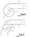
- FIG. 3is an elevation of a duct according to a first embodiment incorporating a right-angular change in direction
- FIG. 4is a side elevation of a duct according to the first embodiment
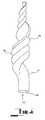
- FIG. 5is an isometric views of a duct according to a second embodiment
- FIG. 6is an end view of a duct according to the second embodiment
- FIG. 7is an diagrammatic view of a duct or stent according to a third embodiment
- FIG. 8is a side elevation of a duct according to a fourth embodiment
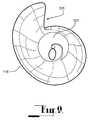
- FIG. 9is an end view of a duct according to the fourth embodiment.
- FIG. 10is an isometric view of a duct according to a fifth embodiment
- FIG. 11is an end view of a duct according to the fifth embodiment.
- FIG. 12is a diagrammatic side elevation (partially sectionalised) of an expansion chamber according to a sixth embodiment
- FIG. 13is a cross-sectional view of the seventh embodiment
- FIG. 14is a diagrammatic isometric view of an expansion chamber according to a seventh embodiment
- FIG. 15is an end view of the seventh embodiment as shown in FIG. 14 .
- Each of the embodimentsis directed to a duct which provides a fluid pathway which can be utilised to convey a fluid.
- Each of the embodimentsserves to, in the greater part, enable fluids to move in their naturally preferred way, thereby reducing inefficiencies created through turbulence and friction which are normally found in apparatus commonly used for propagating fluid flow.
- Previously developed technologieshave generally been less compliant with natural fluid flow tendencies.
- the greater percentage of the surfaces of the ducts of each of the embodiments described hereinare generally designed in the greater part, in accordance with the Golden Section or Ratio and therefore it is a characteristic of each of the embodiments that the duct provides a fluid pathway which is of a spiralling configuration and which conforms at least in greater part to the characteristics of the Golden Section or Ratio.
- the curvature of the surfaces which form the ducttakes a two dimensional or three dimensional shape equivalent to the lines of vorticity or streak lines found in a naturally occurring vortex, and which substantially or in the greater part conform to the characteristics of the Golden Section or Ratio and that any variation in cross-sectional area of the fluid pathway also substantially or in greater part conforms to the characteristics of the Golden Section or Ratio.
- the characteristics of the Golden Section or Ratioare found in nature in the form of the external and internal configurations of shells of the phylum Mollusca, classes Gastropoda and Cephalopoda and it is a common characteristic of at least some of the embodiments that the fluid pathway defined by the duct corresponds generally to the external or internal configuration of shells of one or more of the genera of the phylum Mollusca, classes Gastropoda and Cephalopoda. ⁇
- a first embodiment shown in FIG. 3 and FIG. 4relates to a duct section which facilitates the change in direction of fluid or fluid pathways within plumbing or ducting systems such as water pipes or air conditioning systems.
- a conventional right angle bend ( 30 ) in pipe or ductingresults in fluid flow that is less than optimal.
- Streamlinesshow a low-pressure area ( 31 ) and a high-pressure area ( 32 ). This can result in turbulence, cavitation, sedimentation and corrosion as well as increasing energy losses in the fluid movement ( 34 ). This can result in increased pumping costs and reduced pressure at the outlet.
- FIGS. 3 and 4This form of the embodiment shown in FIGS. 3 and 4 provides a duct ( 36 ) specifically designed to induce the fluid ( 34 ) to move in accordance with the laws of Nature whilst changing its direction.
- the ductis designed having a pathway having a curvature ( 37 ) substantially or in greater part conforming to that of the Golden Section or Ratio.
- the fluidis thereby induced into vortical flow ( 35 ) the greater part of which conforms to the Golden Section or Ratio.
- a second embodiment shown in FIGS. 5 and 6relates to a duct ( 41 ) providing a twisting pathway ( 42 ) for fluids where the pathway conforms to the Golden Section or Ratio.
- fluid ( 43 )flows through the inside ( 44 ) of the duct, it is urged to conform to natural flow spiral characteristics, which minimize extraneous turbulence.
- a flow controllerhaving the form as shown in FIGS. 5 and 6 , the flow controller adapted to be located within a fluid pathway.
- the flow of the fluidis around the outside of the flow controller. It is therefore the external surface of the flow controller which is active and is designed to conform to the Golden Section.
- the flow controllermay be hollow which allows the fluid to flow through it internally.
- a third embodiment shown in FIG. 7depicts a duct ( 51 ) providing a twisting pathway ( 52 ) for fluids conforming to the Golden Section or Ratio. As fluid ( 53 ) flows through the inside or outside of the duct it is urged to conform to natural flow spiral characteristics, which minimize extraneous turbulence. Additionally, the diagram shows the fluid's spiralling flow path on the fluid as it flows.
- An example of a duct constructed in accordance with the third embodimentis a cardiovascular stent.
- stentsConventionally, stents have been cylindrical in shape. While intended to be permanently placed within the patient, it has been found in many cases, that fatty deposits are formed within the stent over a period of time, requiring their replacement. It is believed that this build up is caused as a result of the turbulence in the stent.
- a stent constructed in accordance with the third embodimentwill avoid this turbulent flow and thereby prevent the formation of fatty deposits in the stent.
- the fourth embodiments as shown at FIGS. 8 , 9 , 10 and 11each comprises a fluid flow controller 118 which generally takes the form of a shell of the phylum Mollusca, class Gastropoda, genus Volutidae as shown at FIGS. 8 and 9 and 10 and 11 where the inner end of the shell is cut away as shown to provide an entry ( 121 ) into the interior of the shell.
- the mouth of the shellserves as the outlet ( 125 ) for the controller 118 .
- FIGS. 10 and 11show twin ducts.
- the controllers according to the fourth embodimentsare placed along the fluid flow path to induce a fluid flow that conforms with Nature.
- a further embodimentrelates to a muffler or sound attenuator for a sound source such as an internal combustion engine. It also serves the function of a flame duct or tube to maximise fuel/air combustion and exhaust gas extraction from an internal combustion engine and/or the optimum extraction of energy via adiabatic expansion.
- the inventionalso has application to mufflers, flame tubes and exhaust systems.
- a typical exhaust systemwill have a length of exhaust pipe extending from the engine for sufficient distance to provide an effective flame tube, a contained area in which gas turbulence is minimised and a harmonic is created. This then enters a muffler which is usually a box or chamber with an inlet pipe and outlet pipe. There are baffles, or obstructions within the box which slow down the exhaust gases passing through the box. The box itself, being larger than the inlet pipe allows the exhaust gas to expand, thereby slowing the gas. These reductions in gas speed result in a reduction in noise.
- Muffler systems of this typecan suffer from operational difficulties and inefficiencies ie. the baffling and slowing of exhaust gases in this way causes turbulence and back pressure on the gas and therefore at exhaust of the engine, resulting in reduced performance and efficiency.
- racing cars and bikeshave no mufflers on their exhaust systems but, instead use tuned flame tube ducts which act as extractors of exhaust gases, thereby reducing turbulence and maximising engine power output as a result. They are, of course, very noisy.
- the flame tube/exhaust pipemay be applications of the flow controller of the second, third or fourth embodiments to thereby improve the efficiency of the system.
- the muffler according to the present inventionaims to overcome these problems by providing a muffler which acts as an expansion chamber configuration to reduce the severity of changes in speed or velocity of the gases passing through it, thereby reducing the noise in the system.
- the embodimentalso seeks to take advantage of natural fluid movement tendency which has been observed in Nature to generally form vortices which have a logarithmic spiral.
- These spiral expansion-contraction ratiosas used in the invention, also offer the path of maximum non turbulent adiabatic expansion for gases and therefore provides for greatest efficiency in steam expansion ducts/chambers.
- a rotational-formed expansion chamberwhich acts as a chamber or expansion tube.
- the ductis shaped and expanded to a logarithmic curve configuration.
- the logarithmic curveis arranged so that the entry of gas is at the fine end and the exit is at the coarse or wider end of the chamber.
- logarithmic curveor logarithmic progression
- any form of curve following a logarithmic progressionis included within this definition, including so-called exponential configurations.
- Any curve which approximates an equiangular logarithmic curveis also included within the term “logarithmic curve” used in this specification.
- logarithmic curve configuration for exhaust ductsmay be used and may achieve desired effects, i.e. the reduction of cavitation and the more efficient exhausting and silencing of gases and optimised adiabatic expansion, it is felt that the preferred logarithmic progression is that curve referred to as “the Golden Ratio” in which the logarithmic curve fits within a series of conjoint rectangles, each having their sides in the approximate proportion of 1:0.618.
- the embodimentstems from a desire to decelerate the gases in an exhaust system in a manner in which is harmonious with the natural forms of movement of gases.
- the embodimentestablishes largely singular, vortical flow with minimal counterproductive turbulence which is extraneous to main flow. It is also designed to optimise inherent flame tube/duct characteristics for the maximum combustion of gases.
- the embodimentaims to move and decelerate the gases within an exhaust system duct by the use of vanes or expansion chambers formed to a logarithmic curve so that the gas is caused to decelerate or gradually at first followed by a progressively increasing change of speed in a continual direction change approximating a Golden Ratio logarithmic progression.
- Mufflers using a rotationally formed logarithmically expanding ductmay be used in any suitable application for the expansion and/or muffling of gases, and even for the extraction of air and other gases, but typically finds application in internal combustion engine exhaust systems.
- the gascan be induced through the entry to the duct system, decelerated smoothly using the logarithmic curved vanes and/or chambers, in harmony with the naturally occurring responses of the gas, and ejected at low velocity to cause slowing and noise reduction of gases.
- a mufflermay be provided in a large number of different configurations which are typified by the examples shown in the accompanying drawings.
- FIG. 12there is shown a muffler ( 218 )/expansion chamber ( 211 ) having an entry section ( 221 ) and an exit section ( 225 ) in the form of a converging or diverging duct respectively.
- the muffleris shaped to follow a logarithmic curve having a fine pitch in the area ( 221 ) adjacent the inlet and the relatively coarse pitch in the area adjacent the outlet ( 225 ). Gases forced into the inlet ( 221 ) are caused to slowly decelerate and rotate in a vortex movement, following a natural movement for gases.
- the expansion chambermay be located within a shroud ( 411 ).
- the chamberhas a spiral wall orientated about an axis ( 423 ) and having an edge ( 425 ) from which the conical wall spirals inwardly in a manner following a logarithmic progression.
- the cross section of the cavity between adjacent wallsincreases outwardly in a logarithmic progression causing deceleration of the fluid within the cavity.
- Rotation of the gas in the chamberis in a clockwise sense (with regard to FIG. 8 ), inducted through entry ( 415 ) and forced through the outwardly tapering spiral canals within the impeller until it is thrust out through the exit ( 425 ).
- the spiral tube forming the expansion chamber ( 418 )preferably has a relatively large cross-section at the outlet ( 425 ) and a relatively small cross-section at the inlet ( 423 ), from which gas is inducted at high velocity and caused to be ejected from outlet ( 425 ) resulting in expanded, slowed noise, gas.
- FIG. 15is a typical view from the top of such a chamber from which it can be seen that the shape incorporates a logarithmic curve in its spiral configuration.
- This logarithmic curve or spiral in the approximate ratio of 1:0.618 applied to chambers, vanes or ducts shaped according to this curveare able to operate in a harmonious manner with the natural movement of gas allowing these fluids to be decelerated through a chamber or motor in a manner which is considerably more harmonious, and therefore efficient than that achieved in conventional mufflers, expansion chambers and flame tubes.
- each of the embodiments described abovecan be used as a duct which can induce fluid flow in a non-turbulent manner between an inlet and an outlet or alternatively which permits the passage of fluid between the inlet and outlet in a substantially non-turbulent, more efficient manner than has been possible with conventional ducts of equivalent capacity.
- the duct of the invention and each of the embodimentscan be used with gaseous, liquid and slurry forms of fluid medium.
- the induced vortical flow of the fluidreduces sedimentation of materials in suspension on the walls of the duct.
- the inletprovides the minimum clearance for the fluid entering the duct and as a result any materials which are able pass into the inlet will be able to pass through the duct which reduces the possibility of the duct becoming clogged.
- the duct of the inventionhas application to use in, among others: plumbing systems, refrigeration, circulatory piping or ducting systems, hot gas or refrigerant gas expansion/contraction systems, afterburners, smoke stacks, flues, combustion chambers, air-conditioning ducts, dust precipitators, sound attenuators and mufflers, and can be used to advantage in any proposed application of such, at least because of the enhanced fluid flow, reduced friction, and reduced heat gain, reduced sedimentation, reduced oxidisation, and reduced noise.
Landscapes
- Engineering & Computer Science (AREA)
- General Engineering & Computer Science (AREA)
- Mechanical Engineering (AREA)
- Physics & Mathematics (AREA)
- Fluid Mechanics (AREA)
- Chemical & Material Sciences (AREA)
- Combustion & Propulsion (AREA)
- Theoretical Computer Science (AREA)
- Exhaust Silencers (AREA)
- Pipe Accessories (AREA)
- Flow Control (AREA)
Abstract
Description
Claims (3)
Priority Applications (2)
| Application Number | Priority Date | Filing Date | Title |
|---|---|---|---|
| US13/185,490US8381870B2 (en) | 2002-01-03 | 2011-07-18 | Fluid flow controller |
| US13/778,077US8733497B2 (en) | 2002-01-03 | 2013-02-26 | Fluid flow controller |
Applications Claiming Priority (5)
| Application Number | Priority Date | Filing Date | Title |
|---|---|---|---|
| AUPR9823 | 2002-01-03 | ||
| AUPR9823AAUPR982302A0 (en) | 2002-01-03 | 2002-01-03 | A fluid flow controller |
| PCT/AU2003/000004WO2003056228A1 (en) | 2002-01-03 | 2003-01-03 | A fluid flow controller |
| US10/882,412US7980271B2 (en) | 2002-01-03 | 2004-06-30 | Fluid flow controller |
| US13/185,490US8381870B2 (en) | 2002-01-03 | 2011-07-18 | Fluid flow controller |
Related Parent Applications (1)
| Application Number | Title | Priority Date | Filing Date |
|---|---|---|---|
| US10/882,412ContinuationUS7980271B2 (en) | 2002-01-03 | 2004-06-30 | Fluid flow controller |
Related Child Applications (1)
| Application Number | Title | Priority Date | Filing Date |
|---|---|---|---|
| US13/778,077ContinuationUS8733497B2 (en) | 2002-01-03 | 2013-02-26 | Fluid flow controller |
Publications (2)
| Publication Number | Publication Date |
|---|---|
| US20120016461A1 US20120016461A1 (en) | 2012-01-19 |
| US8381870B2true US8381870B2 (en) | 2013-02-26 |
Family
ID=3833435
Family Applications (4)
| Application Number | Title | Priority Date | Filing Date |
|---|---|---|---|
| US10/882,412Expired - Fee RelatedUS7980271B2 (en) | 2002-01-03 | 2004-06-30 | Fluid flow controller |
| US11/924,144Expired - Fee RelatedUS7644804B2 (en) | 2002-01-03 | 2007-10-25 | Sound attenuator |
| US13/185,490Expired - Fee RelatedUS8381870B2 (en) | 2002-01-03 | 2011-07-18 | Fluid flow controller |
| US13/778,077Expired - Fee RelatedUS8733497B2 (en) | 2002-01-03 | 2013-02-26 | Fluid flow controller |
Family Applications Before (2)
| Application Number | Title | Priority Date | Filing Date |
|---|---|---|---|
| US10/882,412Expired - Fee RelatedUS7980271B2 (en) | 2002-01-03 | 2004-06-30 | Fluid flow controller |
| US11/924,144Expired - Fee RelatedUS7644804B2 (en) | 2002-01-03 | 2007-10-25 | Sound attenuator |
Family Applications After (1)
| Application Number | Title | Priority Date | Filing Date |
|---|---|---|---|
| US13/778,077Expired - Fee RelatedUS8733497B2 (en) | 2002-01-03 | 2013-02-26 | Fluid flow controller |
Country Status (11)
| Country | Link |
|---|---|
| US (4) | US7980271B2 (en) |
| EP (1) | EP1470360A4 (en) |
| JP (1) | JP2005525510A (en) |
| KR (1) | KR20040073535A (en) |
| CN (1) | CN1612989A (en) |
| AU (1) | AUPR982302A0 (en) |
| CA (1) | CA2471818A1 (en) |
| DE (1) | DE03726968T1 (en) |
| EA (1) | EA008045B1 (en) |
| MX (1) | MXPA04006591A (en) |
| WO (1) | WO2003056228A1 (en) |
Cited By (3)
| Publication number | Priority date | Publication date | Assignee | Title |
|---|---|---|---|---|
| US20120298340A1 (en)* | 2011-05-25 | 2012-11-29 | Al-Otaibi Abdullah M | Turbulence-inducing devices for tubular heat exchangers |
| US8733497B2 (en)* | 2002-01-03 | 2014-05-27 | Pax Scientific, Inc. | Fluid flow controller |
| US9624748B2 (en) | 2014-01-24 | 2017-04-18 | Cameron International Corporation | Low shear trim |
Families Citing this family (38)
| Publication number | Priority date | Publication date | Assignee | Title |
|---|---|---|---|---|
| EP1470338A4 (en) | 2002-01-03 | 2012-01-11 | Pax Scient Inc | Vortex ring generator |
| AUPR982502A0 (en)* | 2002-01-03 | 2002-01-31 | Pax Fluid Systems Inc. | A heat exchanger |
| AU2003903386A0 (en) | 2003-07-02 | 2003-07-17 | Pax Scientific, Inc | Fluid flow control device |
| CA2544516C (en) | 2003-11-04 | 2014-04-29 | Pax Scientific, Inc. | Fluid circulation system |
| JP4695097B2 (en)* | 2004-01-30 | 2011-06-08 | パックス サイエンティフィック インコーポレイテッド | Centrifugal fan, pump or turbine housing |
| CN1985093A (en)* | 2004-01-30 | 2007-06-20 | 百思科技公司 | Housing for a centrifugal fan, pump or turbine |
| GB2418362C (en)* | 2004-09-22 | 2010-05-05 | Veryan Medical Ltd | Stent |
| US8808354B2 (en) | 2004-09-22 | 2014-08-19 | Veryan Medical Limited | Helical stent |
| USD570996S1 (en) | 2006-09-25 | 2008-06-10 | Pax Scientific, Inc. | Rotor |
| ES2643620T3 (en)* | 2006-09-28 | 2017-11-23 | Watreco Ip Ab | Vortex Generator |
| US8328522B2 (en) | 2006-09-29 | 2012-12-11 | Pax Scientific, Inc. | Axial flow fan |
| USD570999S1 (en) | 2006-11-22 | 2008-06-10 | Pax Scientific, Inc. | Rotor |
| WO2008127156A1 (en)* | 2007-04-16 | 2008-10-23 | Volvo Lastvagnar Ab | Device for use in exhaust aftertreatment system |
| EP4342518A3 (en)* | 2007-10-11 | 2024-04-03 | Holdica Ltd. | Apparatus for controlling flow of urine in bladder or urethra |
| GB0903554D0 (en) | 2009-03-02 | 2009-04-08 | Wheeler Russell | A fluid transfer pipe and fluid transfer apparatus and a fluid attenuator and attenuator apparatus |
| RU2457014C2 (en)* | 2010-09-07 | 2012-07-27 | Федеральное государственное образовательное учреждение высшего профессионального образования "Кубанский государственный аграрный университет" | Device to change direction of fluid and gas flows |
| DE102012102273A1 (en)* | 2012-03-19 | 2013-09-19 | B. Braun Melsungen Ag | Device for feeding and dosing a fluid for medical purposes |
| US9772157B2 (en)* | 2013-01-23 | 2017-09-26 | John Arthur Yoakam | Projectile launching device |
| US8794217B1 (en) | 2013-02-07 | 2014-08-05 | Thrival Tech, LLC | Coherent-structure fuel treatment systems and methods |
| US10252784B2 (en) | 2013-03-15 | 2019-04-09 | John Ioan Restea | Apparatus for propelling fluid, especially for propulsion of a floating vehicle |
| JP5850877B2 (en)* | 2013-04-25 | 2016-02-03 | 京セラドキュメントソリューションズ株式会社 | Image forming apparatus |
| US10753526B2 (en)* | 2013-12-04 | 2020-08-25 | Bulk Tank Inc. | Unload elbow with spherical wear pocket |
| RO129972B1 (en)* | 2014-08-29 | 2017-09-29 | Viorel Micula | Modular system of swirling entrainment and controlled orientability of hot air streams |
| EP3289050B1 (en)* | 2015-04-30 | 2019-06-19 | Tanfoglio, Domenico | Pyrolysis furnace |
| DE102015005611A1 (en)* | 2015-04-30 | 2016-11-03 | Samson Aktiengesellschaft | Throttle body with several spiral channels running in the space spiral |
| CN106382413B (en)* | 2016-09-29 | 2018-11-16 | 裴学华 | Noise-eliminating tap |
| WO2018102887A1 (en)* | 2016-12-08 | 2018-06-14 | Construkta World Pty Ltd | Pipe fitting |
| US11154410B2 (en)* | 2018-06-29 | 2021-10-26 | Monarch Biosciences, Inc. | Spiral-based thin-film mesh systems and related methods |
| US11396367B2 (en)* | 2019-05-08 | 2022-07-26 | The Boeing Company | Vortex reduction apparatus for use with airfoils |
| ES2804077A1 (en)* | 2019-07-31 | 2021-02-03 | Tecn Biomedicas Para La Salud S L | Acoustic silencer |
| JP7226175B2 (en)* | 2019-07-31 | 2023-02-21 | トヨタ自動車株式会社 | Piping and brake system |
| CN111720390B (en)* | 2019-10-08 | 2021-08-17 | 中国科学院上海微系统与信息技术研究所 | A fluid velocity stabilization system |
| CN110926028B (en)* | 2019-10-30 | 2022-04-22 | 青岛经济技术开发区海尔热水器有限公司 | Steady flow subassembly, insulating part and water heater |
| CN114198589B (en)* | 2021-11-05 | 2023-06-23 | 中国船舶重工集团公司第七一九研究所 | Bent pipe structure fatigue relieving system and structure fatigue relieving control method |
| CN116222129B (en)* | 2021-12-03 | 2024-09-10 | 青岛海尔电冰箱有限公司 | Refrigerator and control method thereof |
| CN114969983A (en)* | 2022-06-13 | 2022-08-30 | 南京航空航天大学 | Bionic conch shell impact-resistant bearing structure and forming method thereof |
| US20240257793A1 (en)* | 2023-01-27 | 2024-08-01 | U.S. Army DEVCOM, Army Research Laboratory | Metamaterial Acoustic Barrier Using Vortex Generation for Internal Circulation |
| CN116857477B (en)* | 2023-08-16 | 2025-08-19 | 南京信息职业技术学院 | Through pipeline and spiral pipeline conversion device |
Citations (170)
| Publication number | Priority date | Publication date | Assignee | Title |
|---|---|---|---|---|
| US11544A (en) | 1854-08-22 | William | ||
| US700785A (en) | 1901-03-22 | 1902-05-27 | Albert L Kull | Muffler for explosive or other engines. |
| US794926A (en) | 1903-05-04 | 1905-07-18 | Benjamin Crawford | Exhaust-muffler. |
| US825010A (en)* | 1905-12-27 | 1906-07-03 | Benjamin W Snow | Muffler. |
| US871825A (en) | 1906-09-07 | 1907-11-26 | Ludwig Schupmann | Projectile for rifled firearms. |
| US879583A (en) | 1906-05-16 | 1908-02-18 | Arthur Pratt | Exhaust-muffler. |
| US938101A (en)* | 1909-02-05 | 1909-10-26 | Harry B Winters | Muffler. |
| US943233A (en) | 1909-08-28 | 1909-12-14 | John Boyle | Exhaust-muffler. |
| US965135A (en) | 1908-12-30 | 1910-07-19 | Hugo C Gibson | Internal-combustion engine. |
| US969101A (en) | 1909-02-05 | 1910-08-30 | Hugo C Gibson | Muffler. |
| US1023225A (en) | 1911-06-22 | 1912-04-16 | Mckenzie Cleland | Muffler for automobiles. |
| US1272180A (en) | 1917-06-26 | 1918-07-09 | Vacuum Muffler Corp | Muffler. |
| US1353478A (en) | 1919-09-09 | 1920-09-21 | George W Kirk | Muffler |
| US1356676A (en) | 1919-01-28 | 1920-10-26 | Automobile-radiator | |
| US1396583A (en) | 1920-05-08 | 1921-11-08 | Krafve William | Muffler |
| US1471697A (en) | 1922-09-09 | 1923-10-23 | Kubes Frantisek | Apparatus for making sugar fondant |
| US1505893A (en) | 1920-03-06 | 1924-08-19 | Hunter William | Silencer for internal-combustion engines |
| US1658126A (en) | 1926-07-05 | 1928-02-07 | Emanuel Hertz | Muffler for internal-combustion engines |
| US1667186A (en) | 1927-05-31 | 1928-04-24 | William R Bluehdorn | Muzzle attachment for guns |
| US1709217A (en) | 1928-03-15 | 1929-04-16 | Francis F Hamilton | Exhaust muffler |
| US1713047A (en) | 1924-11-14 | 1929-05-14 | Maxim Silencer Co | Means for adjusting oscillation period of exhausts of internal-combustion engines |
| US1729018A (en) | 1925-11-05 | 1929-09-24 | Siders Wesley | Muffler for automobile engines |
| US1756916A (en) | 1927-01-24 | 1930-04-29 | Gen Motors Corp | Muffler |
| US1785460A (en) | 1925-03-02 | 1930-12-16 | Robert Suczek | Pump or the like |
| US1799039A (en) | 1929-09-16 | 1931-03-31 | Conejos Anthony | Heat extractor |
| US1812413A (en) | 1929-01-24 | 1931-06-30 | Maxim Silencer Co | Silencer |
| US1816245A (en) | 1929-04-06 | 1931-07-28 | Lester J Wolford | Exhaust silencer |
| US1872075A (en) | 1929-01-24 | 1932-08-16 | Gen Motors Corp | Air cleaner and muffler |
| US1891170A (en) | 1930-06-13 | 1932-12-13 | Nose Toichi | Aeroplane |
| US1919250A (en) | 1931-11-06 | 1933-07-25 | Joseph W Droll | Propeller wheel for fans |
| US2068686A (en) | 1934-11-27 | 1937-01-26 | Lascroux Joseph Louis | Apparatus for silencing the exhaust of internal combustion engines |
| US2085796A (en) | 1935-11-05 | 1937-07-06 | Tube Turns Inc | Method of making reducers |
| US2139736A (en) | 1936-11-19 | 1938-12-13 | Kenneth P Durham | Vortical muffling device |
| US2165808A (en) | 1937-05-22 | 1939-07-11 | Murphy Daniel | Pump rotor |
| US2210031A (en) | 1936-08-28 | 1940-08-06 | Pfaudler Co Inc | Refrigerating apparatus and method |
| US2359365A (en) | 1943-05-20 | 1944-10-03 | Katcher Morris | Muffler |
| US2552615A (en)* | 1948-05-29 | 1951-05-15 | Lawrence F Baltzer | Muffler with spiral conical insert |
| US2784797A (en)* | 1954-07-13 | 1957-03-12 | John H Bailey | Muffler |
| US2879861A (en) | 1956-11-16 | 1959-03-31 | Fred J Belsky | Flow control unit |
| US2908344A (en) | 1958-03-24 | 1959-10-13 | Maruo Hisao | Muffler |
| US2912063A (en) | 1953-04-13 | 1959-11-10 | Barnes Ralph Glenn | Muffler |
| US2958390A (en) | 1957-03-18 | 1960-11-01 | Owens Illinois Glass Co | Sound muffling device |
| GB873135A (en) | 1956-08-01 | 1961-07-19 | Marc Marie Paul Rene De La Fou | Improvements in or relating to engine exhaust systems |
| US3066755A (en) | 1960-04-21 | 1962-12-04 | Diehl William Carl | Muffler with spiral partition |
| US3071159A (en) | 1958-04-19 | 1963-01-01 | Coraggioso Corrado Bono | Heat exchanger tube |
| US3076480A (en) | 1959-04-09 | 1963-02-05 | Vicard Pierre Georges | Fluid conduits |
| US3081826A (en) | 1960-01-27 | 1963-03-19 | Loiseau Christophe | Ship propeller |
| US3082695A (en) | 1959-06-15 | 1963-03-26 | Klein Schanzlin & Becker Ag | Impellers, especially single vane impellers for rotary pumps |
| US3182748A (en)* | 1961-08-15 | 1965-05-11 | Garrett Corp | Helical vane for sound absorbing device and method of making said vane |
| US3215165A (en) | 1963-05-27 | 1965-11-02 | Cons Paper Bahamas Ltd | Method and device for the control of fluid flow |
| US3232341A (en) | 1960-02-01 | 1966-02-01 | Garrett Corp | Condenser |
| US3339631A (en) | 1966-07-13 | 1967-09-05 | James A Mcgurty | Heat exchanger utilizing vortex flow |
| US3371472A (en) | 1965-12-08 | 1968-03-05 | John Krizman Jr. | Spark arrester |
| US3381774A (en)* | 1967-07-10 | 1968-05-07 | Mercury Metal Products Inc | Muffler with interconnected end bells and telescoped inner pipe |
| US3407995A (en) | 1966-10-12 | 1968-10-29 | Lau Blower Co | Blower assembly |
| US3584701A (en) | 1970-04-07 | 1971-06-15 | Michael W Freeman | Sound and resonance control device |
| US3636983A (en) | 1970-08-14 | 1972-01-25 | Edwin J Keyser | Method and apparatus for increasing fluid flow |
| US3688868A (en)* | 1971-08-26 | 1972-09-05 | Stephen J Gibel | Expansion chambered, fail-safe muffler |
| US3692422A (en) | 1971-01-18 | 1972-09-19 | Pierre Mengin Ets | Shearing pump |
| US3800951A (en) | 1968-12-23 | 1974-04-02 | Bertin & Cie | Apparatus for removing a substance floating as a layer on the surface of a body of liquid |
| US3918829A (en) | 1974-06-19 | 1975-11-11 | Warren Pumps Inc | Low pressure-pulse kinetic pump |
| US3927731A (en) | 1974-04-10 | 1975-12-23 | Carter James B Ltd | Muffler with spiral duct and double inlets |
| US3940060A (en) | 1974-08-23 | 1976-02-24 | Hermann Viets | Vortex ring generator |
| US3957133A (en) | 1975-09-10 | 1976-05-18 | Scovill Manufacturing Company | Muffler |
| US3964841A (en) | 1974-09-18 | 1976-06-22 | Sigma Lutin, Narodni Podnik | Impeller blades |
| US3970167A (en)* | 1975-05-12 | 1976-07-20 | Irvin Joseph C | Rotary flow muffler |
| US4050539A (en) | 1975-09-13 | 1977-09-27 | Teruo Kashiwara | Exhaust apparatus for internal combustion engine |
| JPS54129699A (en) | 1978-03-29 | 1979-10-08 | Kazunori Takenaka | Fluid resistance attenuator |
| US4182596A (en) | 1978-02-16 | 1980-01-08 | Carrier Corporation | Discharge housing assembly for a vane axial fan |
| US4206783A (en) | 1977-03-22 | 1980-06-10 | Hansjoerg Brombach | Vortex chamber valve |
| US4211183A (en) | 1977-08-08 | 1980-07-08 | Hoult David P | Fish raising |
| EP0014257A2 (en) | 1979-01-26 | 1980-08-20 | Sperry Vickers Zweigniederlassung der Sperry GmbH | Fluid silencer |
| US4225102A (en) | 1979-03-12 | 1980-09-30 | The United States Of America As Represented By The Administrator Of The National Aeronautics And Space Administration | Aerodynamic side-force alleviator means |
| GB2057567A (en) | 1979-08-24 | 1981-04-01 | Borg Warner | Expanding scroll diffuser for radial flow impeller |
| GB2063365A (en) | 1979-10-08 | 1981-06-03 | Punker Gmbh | Radial Flow Fans |
| US4286976A (en)* | 1979-01-29 | 1981-09-01 | Eriksson Gunar | Combined sound damper and oil trap for a compressed air apparatus |
| US4299553A (en) | 1979-12-14 | 1981-11-10 | The Continental Group, Inc. | Hot runner manifold flow distributor plug |
| WO1981003201A1 (en) | 1980-04-28 | 1981-11-12 | G Koopmann | Noise reduction system |
| US4317502A (en) | 1979-10-22 | 1982-03-02 | Harris Theodore R | Engine exhaust muffler |
| US4323209A (en) | 1977-07-18 | 1982-04-06 | Thompson Roger A | Counter-rotating vortices generator for an aircraft wing |
| US4331213A (en) | 1980-01-28 | 1982-05-25 | Mitsuko Leith | Automobile exhaust control system |
| US4505297A (en) | 1983-08-02 | 1985-03-19 | Shell California Production Inc. | Steam distribution manifold |
| US4533015A (en) | 1983-02-28 | 1985-08-06 | Hisao Kojima | Sound arresting device |
| US4540334A (en) | 1982-12-22 | 1985-09-10 | Staehle Martin | Open-type centrifugal pump with single-blade impeller |
| US4579195A (en) | 1983-06-02 | 1986-04-01 | Giuseppe Nieri | Exhaust gas silencer |
| US4644135A (en) | 1983-08-29 | 1987-02-17 | The Marley Company | Wall mounted forced air electric heater |
| US4679621A (en) | 1985-02-20 | 1987-07-14 | Paul Grote | Spiral heat exchanger |
| US4685534A (en) | 1983-08-16 | 1987-08-11 | Burstein A Lincoln | Method and apparatus for control of fluids |
| US4693339A (en)* | 1986-10-16 | 1987-09-15 | Newport News Shipbuilding And Dry Dock Company | Muffler for gas inducting machinery generating low frequency noise |
| US4699340A (en) | 1983-11-07 | 1987-10-13 | Vehicle Research Corporation | Laminar vortex pump system |
| WO1987007048A1 (en) | 1986-05-07 | 1987-11-19 | Jørgen Mosbaek Johannessen Aps | Flow rate controller |
| US4823865A (en) | 1988-02-18 | 1989-04-25 | A. O. Smith Corporation | Turbulator construction for a heat exchanger |
| WO1989008750A1 (en) | 1988-03-08 | 1989-09-21 | Johannessen Joergen Mosbaek | A device for controlling fluid flow |
| US4993487A (en) | 1989-03-29 | 1991-02-19 | Sundstrand Corporation | Spiral heat exchanger |
| US4996924A (en) | 1987-08-11 | 1991-03-05 | Mcclain Harry T | Aerodynamic air foil surfaces for in-flight control for projectiles |
| US5010910A (en) | 1990-05-21 | 1991-04-30 | Mobil Oil Corporation | Steam distribution manifold |
| US5040558A (en) | 1990-10-31 | 1991-08-20 | Mobil Oil Corporation | Low thermal stress steam distribution manifold |
| US5058837A (en) | 1989-04-07 | 1991-10-22 | Wheeler Gary O | Low drag vortex generators |
| US5100242A (en) | 1987-03-20 | 1992-03-31 | Brian Latto | Vortex ring mixers |
| US5139215A (en) | 1982-11-26 | 1992-08-18 | The Secretary Of State For Defence In Her Britannic Majesty's Government Of The United Kingdom Of Great Britain And Northern Ireland | Guided missiles |
| US5181537A (en) | 1989-12-12 | 1993-01-26 | Conoco Inc. | Outlet collectors that are rate insensitive |
| US5207397A (en) | 1990-06-08 | 1993-05-04 | Eidetics International, Inc. | Rotatable nose and nose boom strakes and methods for aircraft stability and control |
| US5220955A (en) | 1989-08-12 | 1993-06-22 | Dunsley Heat Limited | Heat exchange apparatus |
| US5249993A (en) | 1991-07-19 | 1993-10-05 | Martin Roland V R | Weed resistant boat propeller |
| US5261745A (en) | 1992-04-13 | 1993-11-16 | Watkins James R | Mixing apparatus with frusto-conically shaped impeller for mixing a liquid and a particulate solid |
| US5266755A (en)* | 1992-11-02 | 1993-11-30 | Chien Kuo Feng | Car silencer for absorbing sound and exhaust pollutants |
| US5312224A (en) | 1993-03-12 | 1994-05-17 | International Business Machines Corporation | Conical logarithmic spiral viscosity pump |
| EP0598253A1 (en) | 1992-11-18 | 1994-05-25 | Shinko Pantec Co., Ltd. | Mixing apparatus and bottom ribbon blade used therein |
| US5320493A (en) | 1992-12-16 | 1994-06-14 | Industrial Technology Research Institute | Ultra-thin low noise axial flow fan for office automation machines |
| US5337789A (en) | 1990-10-29 | 1994-08-16 | Hydro International Limited | Vortex valves |
| WO1997003291A1 (en)* | 1995-07-10 | 1997-01-30 | Jayden David Harman | A rotor |
| US5624229A (en) | 1993-09-17 | 1997-04-29 | Man Gutehoffnungshutte Aktiengesellschaft | Spiral housing for a turbomachine |
| US5661638A (en) | 1995-11-03 | 1997-08-26 | Silicon Graphics, Inc. | High performance spiral heat sink |
| US5741118A (en) | 1994-04-28 | 1998-04-21 | Toto Ltd. | Multiblade radial fan and method for making same |
| US5787974A (en) | 1995-06-07 | 1998-08-04 | Pennington; Robert L. | Spiral heat exchanger and method of manufacture |
| US5824972A (en)* | 1997-05-13 | 1998-10-20 | Butler; Boyd L. | Acoustic muffler |
| US5844178A (en) | 1994-11-08 | 1998-12-01 | Lothringen; Leopold Habsburg | Resonance muffler |
| US5891148A (en) | 1996-02-08 | 1999-04-06 | Deckner; Andregeorges | Inverse helical reamer |
| US5934612A (en) | 1998-03-11 | 1999-08-10 | Northrop Grumman Corporation | Wingtip vortex device for induced drag reduction and vortex cancellation |
| US5943877A (en) | 1997-05-05 | 1999-08-31 | The Joseph Company | Space vehicle freezer including heat exchange unit space use |
| US5954124A (en) | 1997-03-31 | 1999-09-21 | Nec Corporation | Heat exchanging device |
| US6050772A (en) | 1995-08-28 | 2000-04-18 | Toto Ltd. | Method for designing a multiblade radial fan and a multiblade radial fan |
| US6089348A (en)* | 1999-09-22 | 2000-07-18 | Bokor Manufacturing Inc. | Blower noise silencer |
| US6152258A (en)* | 1999-09-28 | 2000-11-28 | Brunswick Corporation | Exhaust system with silencing and water separation capability |
| US6179218B1 (en) | 1996-08-30 | 2001-01-30 | Christopher Gates | Solar powered water fountain |
| WO2001014782A1 (en) | 1999-08-25 | 2001-03-01 | Core Flow Ltd. | Self adaptive segmented orifice device and method |
| US6241221B1 (en) | 1998-05-21 | 2001-06-05 | Natural Aeration, Inc. | Waste pond liquid circulation system having an impeller and spaced pontoons |
| US6273679B1 (en) | 1999-07-28 | 2001-08-14 | Samsung Electronics Co., Ltd. | Centrifugal blower |
| US20020000720A1 (en) | 2000-06-21 | 2002-01-03 | Knowles L. James | Washdown system |
| US6374858B1 (en) | 1998-02-27 | 2002-04-23 | Hydro International Plc | Vortex valves |
| US6382348B1 (en) | 2001-02-09 | 2002-05-07 | Shun-Lai Chen | Twin muffler |
| US6385967B1 (en) | 2000-05-31 | 2002-05-14 | Shun-Lai Chen | Exhaust pipe for motor vehicle muffler |
| US6415888B2 (en) | 2000-06-12 | 2002-07-09 | Lg Electronics Inc. | Muffler |
| US20020148777A1 (en) | 2000-11-24 | 2002-10-17 | Tuszko Wlodzimierz Jon | Long free vortex cylindrical telescopic separation chamber cyclone apparatus |
| US6484795B1 (en) | 1999-09-10 | 2002-11-26 | Martin R. Kasprzyk | Insert for a radiant tube |
| US20030012649A1 (en) | 2001-07-16 | 2003-01-16 | Masaharu Sakai | Centrifugal blower |
| US6588545B1 (en)* | 1999-02-05 | 2003-07-08 | Ok-no Lee | Muffler for internal combustion engine |
| WO2003056228A1 (en) | 2002-01-03 | 2003-07-10 | Pax Scientific, Inc | A fluid flow controller |
| WO2003056269A1 (en) | 2002-01-03 | 2003-07-10 | Pax Scientific, Inc. | Heat exchanger |
| WO2003056190A1 (en) | 2002-01-03 | 2003-07-10 | Pax Scientific, Inc. | Vortex ring generator |
| WO2003056139A1 (en) | 2002-01-03 | 2003-07-10 | Pax Scientific, Inc. | A single or multiple bladed rotor |
| US6604906B2 (en) | 2000-08-04 | 2003-08-12 | Calsonic Kansei Corporation | Centrifugal multiblade blower |
| US6623838B1 (en) | 1998-07-16 | 2003-09-23 | Idemitsu Petrochemical Co., Ltd. | Lightweight resin molded product and production method thereof |
| US20030190230A1 (en) | 2002-04-09 | 2003-10-09 | Koji Ito | Centrifugal blower unit |
| US6632071B2 (en) | 2000-11-30 | 2003-10-14 | Lou Pauly | Blower impeller and method of lofting their blade shapes |
| US6669142B2 (en) | 2000-07-26 | 2003-12-30 | Manuel Munoz Saiz | Lifting arrangement for lateral aircraft surfaces |
| US6684633B2 (en) | 2001-04-27 | 2004-02-03 | Marion Barney Jett | Exhaust device for two-stroke internal combustion engine |
| US20040037986A1 (en) | 1998-12-28 | 2004-02-26 | Tayside University Hospitals Nhs Trust, A British Corporation | Blood-flow tubing |
| US6702552B1 (en) | 1999-11-25 | 2004-03-09 | Jayden David Harman | Impeller having blade(s) conforming to the golden section of a logarithmic curve |
| USD487800S1 (en) | 2003-04-16 | 2004-03-23 | Delta Electronics Inc. | Fan |
| US6817419B2 (en) | 2002-10-30 | 2004-11-16 | John A. Reid | Well production management and storage system controller |
| WO2005003616A1 (en) | 2003-07-02 | 2005-01-13 | Pax Scientific, Inc | Fluid flow control device |
| US20050011700A1 (en) | 2003-07-14 | 2005-01-20 | Dadd Paul M. | Devices for regulating pressure and flow pulses |
| US6892988B2 (en) | 2001-04-11 | 2005-05-17 | Christian Hugues | Cylindrical wing tip with helical slot |
| WO2005045258A1 (en) | 2003-11-04 | 2005-05-19 | Pax Scientific, Inc | Fluid circulation system |
| US20050155916A1 (en) | 2003-07-19 | 2005-07-21 | Tuszko Wlodzimierz J. | Cylindrical telescopic structure cyclone apparatus |
| WO2005073561A1 (en) | 2004-01-30 | 2005-08-11 | Pax Scientific, Inc | Housing for a centrifugal fan, pump or turbine |
| US6932188B2 (en) | 2003-08-26 | 2005-08-23 | Suzhou Kingclean Floorcare Co., Ltd. | Silencer for vacuum cleaner |
| USD509584S1 (en) | 2003-10-08 | 2005-09-13 | Datech Technology Co., Ltd. | Fan wheel with hub fastener |
| US20050205353A1 (en)* | 2004-03-16 | 2005-09-22 | Hui-Fang Chen | Automobile muffler |
| US6959782B2 (en) | 2002-03-22 | 2005-11-01 | Tecumseh Products Company | Tuned exhaust system for small engines |
| US7073626B2 (en)* | 2002-07-04 | 2006-07-11 | 3W-Modellmotoren | Engine exhaust muffler with guide vanes imparting a successively alternating spiral swirl gas flow |
| US7117973B2 (en) | 2001-12-22 | 2006-10-10 | Mann & Hummel Gmbh | Noise suppressor apparatus for a gas duct |
| US20060260869A1 (en)* | 2005-05-18 | 2006-11-23 | Kim Jay S | Muffler having fluid swirling vanes |
| US20070025846A1 (en) | 2004-01-30 | 2007-02-01 | Pax Scientific, Inc. | Vortical flow rotor |
| USD539413S1 (en) | 2003-03-27 | 2007-03-27 | Research Foundation Of The University Of Central Florida, Inc. | High efficiency air conditioner condenser twisted fan blades and hub |
| US7331422B2 (en)* | 2005-07-18 | 2008-02-19 | Alan Wall | Vortex muffler |
| US20080145230A1 (en) | 2006-09-29 | 2008-06-19 | Pax Scientific, Inc. | Axial flow fan |
| US20090308472A1 (en) | 2008-06-15 | 2009-12-17 | Jayden David Harman | Swirl Inducer |
| US20110308884A1 (en)* | 2009-02-05 | 2011-12-22 | Deutsches Zentrum Fur Luft-Und Raumfahrt E.V. | Sound absorber having helical fixtures |
Family Cites Families (36)
| Publication number | Priority date | Publication date | Assignee | Title |
|---|---|---|---|---|
| US3503246A (en)* | 1967-12-28 | 1970-03-31 | Hiroyasu Shiokawa | Method of manufacturing a spiral metal tube |
| SU431850A1 (en) | 1972-07-03 | 1974-06-15 | Специальное Экспериментально-Конструкторское Бюро Промышленного Рыболовства | Submersible fish pump |
| SU850104A1 (en) | 1973-12-24 | 1981-07-30 | Предприятие П/Я Р-6603 | Rotor-type film apparatus |
| SU738566A1 (en) | 1978-01-23 | 1980-06-05 | Киевский Ордена Ленина Государственный Университет Им.Т.Г.Шевченко | Apparatus for keeping aquatic organisms |
| SU687306A1 (en)* | 1978-02-13 | 1979-09-25 | Ленинградская Ордена Ленина Лесотехническая Академия Им. С.М.Кирова | Aerodynamic noise suppressor |
| JPS54129699U (en) | 1978-02-17 | 1979-09-08 | ||
| SE410891B (en)* | 1978-04-03 | 1979-11-12 | Garle Henry Gustaf Elis | Muffler FOR COMPRESSED AIR EMISSIONS FROM COMPRESSED AIR CONTROLLED MACHINES |
| SU887876A1 (en)* | 1979-09-14 | 1981-12-07 | Институт гидромеханики АН УССР | Flow energy suppressor |
| SU858896A1 (en) | 1979-12-19 | 1981-08-30 | Предприятие П/Я Р-6956 | Rotor-type comminuting device |
| SU1030631A1 (en) | 1980-05-26 | 1983-07-23 | Сибирский Научно-Исследовательский И Проектный Институт Цементной Промышленности,Научная Часть | Heat exchange device |
| DE3238913C2 (en) | 1982-10-21 | 1985-10-03 | Werner Dr. 8972 Sonthofen Röhrs | Centrifugal fan housing |
| SU1110986A1 (en)* | 1983-04-26 | 1984-08-30 | Предприятие П/Я Р-6601 | Device for damping liquid oscillations in flow delivery pipeline |
| DE3315258A1 (en) | 1983-04-27 | 1984-10-31 | Etablissement Agura, Vaduz | Spiral ring heating boiler |
| JPS60121115A (en)* | 1983-12-01 | 1985-06-28 | Toyota Motor Corp | Controller for power-operated convertible roof for car |
| US5336789A (en) | 1986-03-12 | 1994-08-09 | American Cyanamid Company | Macrolide compounds |
| SU1418540A2 (en)* | 1986-12-10 | 1988-08-23 | Институт гидромеханики АН УССР | Energy damping and separating apparatus |
| JPH072582B2 (en) | 1987-10-12 | 1995-01-18 | 株式会社中央製作所 | Hanger transport device in surface treatment equipment |
| SU1560887A1 (en)* | 1988-02-04 | 1990-04-30 | Предприятие "Средазтехэнерго" Производственного Объединения По Наладке, Совершенствованию Технологии И Эксплуатации Электростанций И Сетей "Союзтехэнерго" | Gas stream noise muffler |
| FR2666031B1 (en)* | 1990-08-27 | 1993-10-22 | Pierre Saget | PROCESS FOR THE CENTRIFUGAL SEPARATION OF THE PHASES OF A MIXTURE AND CENTRIFUGAL SEPARATOR WITH LONGITUDINAL BLADES USING THIS PROCESS. |
| JPH055536A (en)* | 1990-11-07 | 1993-01-14 | Daikin Ind Ltd | Air conditioner |
| US5282847A (en)* | 1991-02-28 | 1994-02-01 | Medtronic, Inc. | Prosthetic vascular grafts with a pleated structure |
| SU1756724A1 (en)* | 1991-04-30 | 1992-08-23 | Одесский Политехнический Институт | Swirler for two-phase flow |
| JPH0592508U (en)* | 1991-09-20 | 1993-12-17 | 日本電気ホームエレクトロニクス株式会社 | Channel structure |
| JPH05332121A (en)* | 1992-05-29 | 1993-12-14 | Mitsubishi Heavy Ind Ltd | Exhaust muffler |
| DE4332404A1 (en)* | 1993-09-23 | 1995-03-30 | Felder Anton | Device for limiting the flow and at the same time temporarily storing waste water and separating settable and floating substances from dirty water and such a method |
| FR2723329B1 (en)* | 1994-08-02 | 1996-09-13 | Inst Francais Du Petrole | METHOD AND DEVICE FOR MANUFACTURING A CORRUGATED METAL TUBE |
| DE4445794C1 (en)* | 1994-12-21 | 1996-01-25 | Norres Richard | Gas-duct inner tube externally joined to heavy metal formers |
| AU694679B2 (en) | 1995-07-10 | 1998-07-23 | Jayden David Harman | A rotor |
| JPH0953787A (en)* | 1995-08-11 | 1997-02-25 | Kajima Corp | Drain pipe blade |
| JPH09264462A (en)* | 1996-03-29 | 1997-10-07 | Sekisui Chem Co Ltd | Pipe with spiral guide |
| JPH11148591A (en)* | 1997-11-14 | 1999-06-02 | Tlv Co Ltd | Water hammer preventive device |
| JP2000257610A (en) | 1999-03-10 | 2000-09-19 | Tomotaka Marui | Turbulence restraining method by autogenous swirl flow using surface flow of fixed rotor, autogenous swirl flow generating device, autogenous swirl flow generating and maintaining control method and verifying method for turbulence restrain effect |
| BG63583B1 (en)* | 2000-04-12 | 2002-05-31 | СОРОЧИНСКИ Александр | Method for torsion effect of working media and torsion generator realizing the method |
| GB2379996B (en)* | 2001-06-05 | 2004-05-19 | Tayside Flow Technologies Ltd | Flow means |
| EP1509169B1 (en)* | 2002-06-05 | 2012-10-10 | Vascular Flow Technologies Limited | A method of determining the helix angle of a helical formation for a conduit |
| TWM287387U (en) | 2005-08-24 | 2006-02-11 | Delta Electronics Inc | Fan and fan housing with air-guiding static blades |
- 2002
- 2002-01-03AUAUPR9823Apatent/AUPR982302A0/ennot_activeAbandoned
- 2003
- 2003-01-03CACA002471818Apatent/CA2471818A1/ennot_activeAbandoned
- 2003-01-03EPEP03726968Apatent/EP1470360A4/ennot_activeWithdrawn
- 2003-01-03WOPCT/AU2003/000004patent/WO2003056228A1/enactiveIP Right Grant
- 2003-01-03CNCNA038019337Apatent/CN1612989A/enactivePending
- 2003-01-03DEDE03726968Tpatent/DE03726968T1/enactivePending
- 2003-01-03KRKR10-2004-7010412Apatent/KR20040073535A/ennot_activeCeased
- 2003-01-03MXMXPA04006591Apatent/MXPA04006591A/enactiveIP Right Grant
- 2003-01-03EAEA200400901Apatent/EA008045B1/ennot_activeIP Right Cessation
- 2003-01-03JPJP2003556716Apatent/JP2005525510A/enactivePending
- 2004
- 2004-06-30USUS10/882,412patent/US7980271B2/ennot_activeExpired - Fee Related
- 2007
- 2007-10-25USUS11/924,144patent/US7644804B2/ennot_activeExpired - Fee Related
- 2011
- 2011-07-18USUS13/185,490patent/US8381870B2/ennot_activeExpired - Fee Related
- 2013
- 2013-02-26USUS13/778,077patent/US8733497B2/ennot_activeExpired - Fee Related
Patent Citations (199)
| Publication number | Priority date | Publication date | Assignee | Title |
|---|---|---|---|---|
| US11544A (en) | 1854-08-22 | William | ||
| US700785A (en) | 1901-03-22 | 1902-05-27 | Albert L Kull | Muffler for explosive or other engines. |
| US794926A (en) | 1903-05-04 | 1905-07-18 | Benjamin Crawford | Exhaust-muffler. |
| US825010A (en)* | 1905-12-27 | 1906-07-03 | Benjamin W Snow | Muffler. |
| US879583A (en) | 1906-05-16 | 1908-02-18 | Arthur Pratt | Exhaust-muffler. |
| US871825A (en) | 1906-09-07 | 1907-11-26 | Ludwig Schupmann | Projectile for rifled firearms. |
| US965135A (en) | 1908-12-30 | 1910-07-19 | Hugo C Gibson | Internal-combustion engine. |
| US938101A (en)* | 1909-02-05 | 1909-10-26 | Harry B Winters | Muffler. |
| US969101A (en) | 1909-02-05 | 1910-08-30 | Hugo C Gibson | Muffler. |
| US943233A (en) | 1909-08-28 | 1909-12-14 | John Boyle | Exhaust-muffler. |
| US1023225A (en) | 1911-06-22 | 1912-04-16 | Mckenzie Cleland | Muffler for automobiles. |
| US1272180A (en) | 1917-06-26 | 1918-07-09 | Vacuum Muffler Corp | Muffler. |
| US1356676A (en) | 1919-01-28 | 1920-10-26 | Automobile-radiator | |
| US1353478A (en) | 1919-09-09 | 1920-09-21 | George W Kirk | Muffler |
| US1505893A (en) | 1920-03-06 | 1924-08-19 | Hunter William | Silencer for internal-combustion engines |
| US1396583A (en) | 1920-05-08 | 1921-11-08 | Krafve William | Muffler |
| US1471697A (en) | 1922-09-09 | 1923-10-23 | Kubes Frantisek | Apparatus for making sugar fondant |
| US1713047A (en) | 1924-11-14 | 1929-05-14 | Maxim Silencer Co | Means for adjusting oscillation period of exhausts of internal-combustion engines |
| US1785460A (en) | 1925-03-02 | 1930-12-16 | Robert Suczek | Pump or the like |
| US1729018A (en) | 1925-11-05 | 1929-09-24 | Siders Wesley | Muffler for automobile engines |
| US1658126A (en) | 1926-07-05 | 1928-02-07 | Emanuel Hertz | Muffler for internal-combustion engines |
| US1756916A (en) | 1927-01-24 | 1930-04-29 | Gen Motors Corp | Muffler |
| US1667186A (en) | 1927-05-31 | 1928-04-24 | William R Bluehdorn | Muzzle attachment for guns |
| US1709217A (en) | 1928-03-15 | 1929-04-16 | Francis F Hamilton | Exhaust muffler |
| US1872075A (en) | 1929-01-24 | 1932-08-16 | Gen Motors Corp | Air cleaner and muffler |
| US1812413A (en) | 1929-01-24 | 1931-06-30 | Maxim Silencer Co | Silencer |
| US1816245A (en) | 1929-04-06 | 1931-07-28 | Lester J Wolford | Exhaust silencer |
| US1799039A (en) | 1929-09-16 | 1931-03-31 | Conejos Anthony | Heat extractor |
| US1891170A (en) | 1930-06-13 | 1932-12-13 | Nose Toichi | Aeroplane |
| US1919250A (en) | 1931-11-06 | 1933-07-25 | Joseph W Droll | Propeller wheel for fans |
| US2068686A (en) | 1934-11-27 | 1937-01-26 | Lascroux Joseph Louis | Apparatus for silencing the exhaust of internal combustion engines |
| US2085796A (en) | 1935-11-05 | 1937-07-06 | Tube Turns Inc | Method of making reducers |
| US2210031A (en) | 1936-08-28 | 1940-08-06 | Pfaudler Co Inc | Refrigerating apparatus and method |
| US2139736A (en) | 1936-11-19 | 1938-12-13 | Kenneth P Durham | Vortical muffling device |
| US2165808A (en) | 1937-05-22 | 1939-07-11 | Murphy Daniel | Pump rotor |
| US2359365A (en) | 1943-05-20 | 1944-10-03 | Katcher Morris | Muffler |
| US2552615A (en)* | 1948-05-29 | 1951-05-15 | Lawrence F Baltzer | Muffler with spiral conical insert |
| US2912063A (en) | 1953-04-13 | 1959-11-10 | Barnes Ralph Glenn | Muffler |
| US2784797A (en)* | 1954-07-13 | 1957-03-12 | John H Bailey | Muffler |
| GB873135A (en) | 1956-08-01 | 1961-07-19 | Marc Marie Paul Rene De La Fou | Improvements in or relating to engine exhaust systems |
| US2879861A (en) | 1956-11-16 | 1959-03-31 | Fred J Belsky | Flow control unit |
| US2958390A (en) | 1957-03-18 | 1960-11-01 | Owens Illinois Glass Co | Sound muffling device |
| US2908344A (en) | 1958-03-24 | 1959-10-13 | Maruo Hisao | Muffler |
| US3071159A (en) | 1958-04-19 | 1963-01-01 | Coraggioso Corrado Bono | Heat exchanger tube |
| US3076480A (en) | 1959-04-09 | 1963-02-05 | Vicard Pierre Georges | Fluid conduits |
| US3082695A (en) | 1959-06-15 | 1963-03-26 | Klein Schanzlin & Becker Ag | Impellers, especially single vane impellers for rotary pumps |
| US3081826A (en) | 1960-01-27 | 1963-03-19 | Loiseau Christophe | Ship propeller |
| US3232341A (en) | 1960-02-01 | 1966-02-01 | Garrett Corp | Condenser |
| US3066755A (en) | 1960-04-21 | 1962-12-04 | Diehl William Carl | Muffler with spiral partition |
| US3182748A (en)* | 1961-08-15 | 1965-05-11 | Garrett Corp | Helical vane for sound absorbing device and method of making said vane |
| US3215165A (en) | 1963-05-27 | 1965-11-02 | Cons Paper Bahamas Ltd | Method and device for the control of fluid flow |
| US3371472A (en) | 1965-12-08 | 1968-03-05 | John Krizman Jr. | Spark arrester |
| US3339631A (en) | 1966-07-13 | 1967-09-05 | James A Mcgurty | Heat exchanger utilizing vortex flow |
| US3407995A (en) | 1966-10-12 | 1968-10-29 | Lau Blower Co | Blower assembly |
| US3381774A (en)* | 1967-07-10 | 1968-05-07 | Mercury Metal Products Inc | Muffler with interconnected end bells and telescoped inner pipe |
| US3800951A (en) | 1968-12-23 | 1974-04-02 | Bertin & Cie | Apparatus for removing a substance floating as a layer on the surface of a body of liquid |
| US3584701A (en) | 1970-04-07 | 1971-06-15 | Michael W Freeman | Sound and resonance control device |
| US3636983A (en) | 1970-08-14 | 1972-01-25 | Edwin J Keyser | Method and apparatus for increasing fluid flow |
| US3692422A (en) | 1971-01-18 | 1972-09-19 | Pierre Mengin Ets | Shearing pump |
| US3688868A (en)* | 1971-08-26 | 1972-09-05 | Stephen J Gibel | Expansion chambered, fail-safe muffler |
| US3927731A (en) | 1974-04-10 | 1975-12-23 | Carter James B Ltd | Muffler with spiral duct and double inlets |
| US3918829A (en) | 1974-06-19 | 1975-11-11 | Warren Pumps Inc | Low pressure-pulse kinetic pump |
| US3940060A (en) | 1974-08-23 | 1976-02-24 | Hermann Viets | Vortex ring generator |
| US3964841A (en) | 1974-09-18 | 1976-06-22 | Sigma Lutin, Narodni Podnik | Impeller blades |
| US3970167A (en)* | 1975-05-12 | 1976-07-20 | Irvin Joseph C | Rotary flow muffler |
| US3957133A (en) | 1975-09-10 | 1976-05-18 | Scovill Manufacturing Company | Muffler |
| US4050539A (en) | 1975-09-13 | 1977-09-27 | Teruo Kashiwara | Exhaust apparatus for internal combustion engine |
| US4206783A (en) | 1977-03-22 | 1980-06-10 | Hansjoerg Brombach | Vortex chamber valve |
| US4323209A (en) | 1977-07-18 | 1982-04-06 | Thompson Roger A | Counter-rotating vortices generator for an aircraft wing |
| US4211183A (en) | 1977-08-08 | 1980-07-08 | Hoult David P | Fish raising |
| US4182596A (en) | 1978-02-16 | 1980-01-08 | Carrier Corporation | Discharge housing assembly for a vane axial fan |
| JPS54129699A (en) | 1978-03-29 | 1979-10-08 | Kazunori Takenaka | Fluid resistance attenuator |
| EP0014257A2 (en) | 1979-01-26 | 1980-08-20 | Sperry Vickers Zweigniederlassung der Sperry GmbH | Fluid silencer |
| US4286976A (en)* | 1979-01-29 | 1981-09-01 | Eriksson Gunar | Combined sound damper and oil trap for a compressed air apparatus |
| US4225102A (en) | 1979-03-12 | 1980-09-30 | The United States Of America As Represented By The Administrator Of The National Aeronautics And Space Administration | Aerodynamic side-force alleviator means |
| GB2057567A (en) | 1979-08-24 | 1981-04-01 | Borg Warner | Expanding scroll diffuser for radial flow impeller |
| GB2063365A (en) | 1979-10-08 | 1981-06-03 | Punker Gmbh | Radial Flow Fans |
| US4317502A (en) | 1979-10-22 | 1982-03-02 | Harris Theodore R | Engine exhaust muffler |
| US4299553A (en) | 1979-12-14 | 1981-11-10 | The Continental Group, Inc. | Hot runner manifold flow distributor plug |
| US4331213A (en) | 1980-01-28 | 1982-05-25 | Mitsuko Leith | Automobile exhaust control system |
| WO1981003201A1 (en) | 1980-04-28 | 1981-11-12 | G Koopmann | Noise reduction system |
| US5139215A (en) | 1982-11-26 | 1992-08-18 | The Secretary Of State For Defence In Her Britannic Majesty's Government Of The United Kingdom Of Great Britain And Northern Ireland | Guided missiles |
| US4540334A (en) | 1982-12-22 | 1985-09-10 | Staehle Martin | Open-type centrifugal pump with single-blade impeller |
| US4533015A (en) | 1983-02-28 | 1985-08-06 | Hisao Kojima | Sound arresting device |
| US4579195A (en) | 1983-06-02 | 1986-04-01 | Giuseppe Nieri | Exhaust gas silencer |
| US4505297A (en) | 1983-08-02 | 1985-03-19 | Shell California Production Inc. | Steam distribution manifold |
| US4685534A (en) | 1983-08-16 | 1987-08-11 | Burstein A Lincoln | Method and apparatus for control of fluids |
| US4644135A (en) | 1983-08-29 | 1987-02-17 | The Marley Company | Wall mounted forced air electric heater |
| US4699340A (en) | 1983-11-07 | 1987-10-13 | Vehicle Research Corporation | Laminar vortex pump system |
| US4679621A (en) | 1985-02-20 | 1987-07-14 | Paul Grote | Spiral heat exchanger |
| WO1987007048A1 (en) | 1986-05-07 | 1987-11-19 | Jørgen Mosbaek Johannessen Aps | Flow rate controller |
| US4834142A (en) | 1986-05-07 | 1989-05-30 | Jorgen Mosbaek Johannessen Aps | Flow rate controller |
| US4693339A (en)* | 1986-10-16 | 1987-09-15 | Newport News Shipbuilding And Dry Dock Company | Muffler for gas inducting machinery generating low frequency noise |
| US5100242A (en) | 1987-03-20 | 1992-03-31 | Brian Latto | Vortex ring mixers |
| US4996924A (en) | 1987-08-11 | 1991-03-05 | Mcclain Harry T | Aerodynamic air foil surfaces for in-flight control for projectiles |
| US4823865A (en) | 1988-02-18 | 1989-04-25 | A. O. Smith Corporation | Turbulator construction for a heat exchanger |
| WO1989008750A1 (en) | 1988-03-08 | 1989-09-21 | Johannessen Joergen Mosbaek | A device for controlling fluid flow |
| US5052442A (en) | 1988-03-08 | 1991-10-01 | Johannessen Jorgen M | Device for controlling fluid flow |
| US4993487A (en) | 1989-03-29 | 1991-02-19 | Sundstrand Corporation | Spiral heat exchanger |
| US5058837A (en) | 1989-04-07 | 1991-10-22 | Wheeler Gary O | Low drag vortex generators |
| US5220955A (en) | 1989-08-12 | 1993-06-22 | Dunsley Heat Limited | Heat exchange apparatus |
| US5181537A (en) | 1989-12-12 | 1993-01-26 | Conoco Inc. | Outlet collectors that are rate insensitive |
| US5010910A (en) | 1990-05-21 | 1991-04-30 | Mobil Oil Corporation | Steam distribution manifold |
| US5207397A (en) | 1990-06-08 | 1993-05-04 | Eidetics International, Inc. | Rotatable nose and nose boom strakes and methods for aircraft stability and control |
| US5337789A (en) | 1990-10-29 | 1994-08-16 | Hydro International Limited | Vortex valves |
| US5040558A (en) | 1990-10-31 | 1991-08-20 | Mobil Oil Corporation | Low thermal stress steam distribution manifold |
| US5249993A (en) | 1991-07-19 | 1993-10-05 | Martin Roland V R | Weed resistant boat propeller |
| US5261745A (en) | 1992-04-13 | 1993-11-16 | Watkins James R | Mixing apparatus with frusto-conically shaped impeller for mixing a liquid and a particulate solid |
| US5266755A (en)* | 1992-11-02 | 1993-11-30 | Chien Kuo Feng | Car silencer for absorbing sound and exhaust pollutants |
| US5382092A (en) | 1992-11-18 | 1995-01-17 | Shinko Pantec Co., Ltd. | Mixing apparatus and bottom ribbon blade used therein |
| EP0598253A1 (en) | 1992-11-18 | 1994-05-25 | Shinko Pantec Co., Ltd. | Mixing apparatus and bottom ribbon blade used therein |
| US5320493A (en) | 1992-12-16 | 1994-06-14 | Industrial Technology Research Institute | Ultra-thin low noise axial flow fan for office automation machines |
| US5312224A (en) | 1993-03-12 | 1994-05-17 | International Business Machines Corporation | Conical logarithmic spiral viscosity pump |
| US5624229A (en) | 1993-09-17 | 1997-04-29 | Man Gutehoffnungshutte Aktiengesellschaft | Spiral housing for a turbomachine |
| US5741118A (en) | 1994-04-28 | 1998-04-21 | Toto Ltd. | Multiblade radial fan and method for making same |
| US5844178A (en) | 1994-11-08 | 1998-12-01 | Lothringen; Leopold Habsburg | Resonance muffler |
| US5787974A (en) | 1995-06-07 | 1998-08-04 | Pennington; Robert L. | Spiral heat exchanger and method of manufacture |
| WO1997003291A1 (en)* | 1995-07-10 | 1997-01-30 | Jayden David Harman | A rotor |
| US5934877A (en) | 1995-07-10 | 1999-08-10 | Harman; Jayden David | Rotor with logarithmic scaled shape |
| US6050772A (en) | 1995-08-28 | 2000-04-18 | Toto Ltd. | Method for designing a multiblade radial fan and a multiblade radial fan |
| US5661638A (en) | 1995-11-03 | 1997-08-26 | Silicon Graphics, Inc. | High performance spiral heat sink |
| US5891148A (en) | 1996-02-08 | 1999-04-06 | Deckner; Andregeorges | Inverse helical reamer |
| US6179218B1 (en) | 1996-08-30 | 2001-01-30 | Christopher Gates | Solar powered water fountain |
| US5954124A (en) | 1997-03-31 | 1999-09-21 | Nec Corporation | Heat exchanging device |
| US5943877A (en) | 1997-05-05 | 1999-08-31 | The Joseph Company | Space vehicle freezer including heat exchange unit space use |
| US5824972A (en)* | 1997-05-13 | 1998-10-20 | Butler; Boyd L. | Acoustic muffler |
| US6374858B1 (en) | 1998-02-27 | 2002-04-23 | Hydro International Plc | Vortex valves |
| US5934612A (en) | 1998-03-11 | 1999-08-10 | Northrop Grumman Corporation | Wingtip vortex device for induced drag reduction and vortex cancellation |
| US6241221B1 (en) | 1998-05-21 | 2001-06-05 | Natural Aeration, Inc. | Waste pond liquid circulation system having an impeller and spaced pontoons |
| US6623838B1 (en) | 1998-07-16 | 2003-09-23 | Idemitsu Petrochemical Co., Ltd. | Lightweight resin molded product and production method thereof |
| US20040037986A1 (en) | 1998-12-28 | 2004-02-26 | Tayside University Hospitals Nhs Trust, A British Corporation | Blood-flow tubing |
| US6588545B1 (en)* | 1999-02-05 | 2003-07-08 | Ok-no Lee | Muffler for internal combustion engine |
| US6273679B1 (en) | 1999-07-28 | 2001-08-14 | Samsung Electronics Co., Ltd. | Centrifugal blower |
| WO2001014782A1 (en) | 1999-08-25 | 2001-03-01 | Core Flow Ltd. | Self adaptive segmented orifice device and method |
| US6484795B1 (en) | 1999-09-10 | 2002-11-26 | Martin R. Kasprzyk | Insert for a radiant tube |
| US6089348A (en)* | 1999-09-22 | 2000-07-18 | Bokor Manufacturing Inc. | Blower noise silencer |
| US6152258A (en)* | 1999-09-28 | 2000-11-28 | Brunswick Corporation | Exhaust system with silencing and water separation capability |
| US6702552B1 (en) | 1999-11-25 | 2004-03-09 | Jayden David Harman | Impeller having blade(s) conforming to the golden section of a logarithmic curve |
| US6385967B1 (en) | 2000-05-31 | 2002-05-14 | Shun-Lai Chen | Exhaust pipe for motor vehicle muffler |
| US6415888B2 (en) | 2000-06-12 | 2002-07-09 | Lg Electronics Inc. | Muffler |
| US20020000720A1 (en) | 2000-06-21 | 2002-01-03 | Knowles L. James | Washdown system |
| US6669142B2 (en) | 2000-07-26 | 2003-12-30 | Manuel Munoz Saiz | Lifting arrangement for lateral aircraft surfaces |
| US6604906B2 (en) | 2000-08-04 | 2003-08-12 | Calsonic Kansei Corporation | Centrifugal multiblade blower |
| US20020148777A1 (en) | 2000-11-24 | 2002-10-17 | Tuszko Wlodzimierz Jon | Long free vortex cylindrical telescopic separation chamber cyclone apparatus |
| US6632071B2 (en) | 2000-11-30 | 2003-10-14 | Lou Pauly | Blower impeller and method of lofting their blade shapes |
| US6382348B1 (en) | 2001-02-09 | 2002-05-07 | Shun-Lai Chen | Twin muffler |
| US6892988B2 (en) | 2001-04-11 | 2005-05-17 | Christian Hugues | Cylindrical wing tip with helical slot |
| US6684633B2 (en) | 2001-04-27 | 2004-02-03 | Marion Barney Jett | Exhaust device for two-stroke internal combustion engine |
| US20030012649A1 (en) | 2001-07-16 | 2003-01-16 | Masaharu Sakai | Centrifugal blower |
| US7117973B2 (en) | 2001-12-22 | 2006-10-10 | Mann & Hummel Gmbh | Noise suppressor apparatus for a gas duct |
| WO2003056139A1 (en) | 2002-01-03 | 2003-07-10 | Pax Scientific, Inc. | A single or multiple bladed rotor |
| US20080041474A1 (en) | 2002-01-03 | 2008-02-21 | Harman Jayden D | Fluid Flow Controller |
| WO2003056190A1 (en) | 2002-01-03 | 2003-07-10 | Pax Scientific, Inc. | Vortex ring generator |
| US7287580B2 (en) | 2002-01-03 | 2007-10-30 | Pax Scientific, Inc. | Heat exchanger |
| US20080023188A1 (en) | 2002-01-03 | 2008-01-31 | Harman Jayden D | Heat Exchanger |
| US20040238163A1 (en) | 2002-01-03 | 2004-12-02 | Harman Jayden David | Heat exchanger |
| US20040244853A1 (en) | 2002-01-03 | 2004-12-09 | Harman Jayden David | Fluid flow controller |
| US7096934B2 (en) | 2002-01-03 | 2006-08-29 | Pax Scientific, Inc. | Heat exchanger |
| US7980271B2 (en) | 2002-01-03 | 2011-07-19 | Caitin, Inc. | Fluid flow controller |
| WO2003056228A1 (en) | 2002-01-03 | 2003-07-10 | Pax Scientific, Inc | A fluid flow controller |
| US20060249283A1 (en) | 2002-01-03 | 2006-11-09 | Pax Scientific, Inc. | Heat exchanger |
| US7934686B2 (en) | 2002-01-03 | 2011-05-03 | Caitin, Inc. | Reducing drag on a mobile body |
| US20080265101A1 (en) | 2002-01-03 | 2008-10-30 | Pax Scientific, Inc. | Vortex ring generator |
| US7766279B2 (en) | 2002-01-03 | 2010-08-03 | NewPax, Inc. | Vortex ring generator |
| US7673834B2 (en) | 2002-01-03 | 2010-03-09 | Pax Streamline, Inc. | Vortex ring generator |
| US7644804B2 (en) | 2002-01-03 | 2010-01-12 | Pax Streamline, Inc. | Sound attenuator |
| US20110011463A1 (en) | 2002-01-03 | 2011-01-20 | Jayden David Harman | Reducing drag on a mobile body |
| US20050269458A1 (en) | 2002-01-03 | 2005-12-08 | Harman Jayden D | Vortex ring generator |
| US7814967B2 (en) | 2002-01-03 | 2010-10-19 | New Pax, Inc. | Heat exchanger |
| WO2003056269A1 (en) | 2002-01-03 | 2003-07-10 | Pax Scientific, Inc. | Heat exchanger |
| US6959782B2 (en) | 2002-03-22 | 2005-11-01 | Tecumseh Products Company | Tuned exhaust system for small engines |
| US20030190230A1 (en) | 2002-04-09 | 2003-10-09 | Koji Ito | Centrifugal blower unit |
| US7073626B2 (en)* | 2002-07-04 | 2006-07-11 | 3W-Modellmotoren | Engine exhaust muffler with guide vanes imparting a successively alternating spiral swirl gas flow |
| US6817419B2 (en) | 2002-10-30 | 2004-11-16 | John A. Reid | Well production management and storage system controller |
| USD539413S1 (en) | 2003-03-27 | 2007-03-27 | Research Foundation Of The University Of Central Florida, Inc. | High efficiency air conditioner condenser twisted fan blades and hub |
| USD487800S1 (en) | 2003-04-16 | 2004-03-23 | Delta Electronics Inc. | Fan |
| WO2005003616A1 (en) | 2003-07-02 | 2005-01-13 | Pax Scientific, Inc | Fluid flow control device |
| US20100313982A1 (en) | 2003-07-02 | 2010-12-16 | Jayden David Harman | Fluid Flow Control Device |
| US20060102239A1 (en) | 2003-07-02 | 2006-05-18 | Pax Scientific, Inc. | Fluid flow control device |
| US7802583B2 (en) | 2003-07-02 | 2010-09-28 | New Pax, Inc. | Fluid flow control device |
| US20050011700A1 (en) | 2003-07-14 | 2005-01-20 | Dadd Paul M. | Devices for regulating pressure and flow pulses |
| US20050155916A1 (en) | 2003-07-19 | 2005-07-21 | Tuszko Wlodzimierz J. | Cylindrical telescopic structure cyclone apparatus |
| US6932188B2 (en) | 2003-08-26 | 2005-08-23 | Suzhou Kingclean Floorcare Co., Ltd. | Silencer for vacuum cleaner |
| USD509584S1 (en) | 2003-10-08 | 2005-09-13 | Datech Technology Co., Ltd. | Fan wheel with hub fastener |
| US20110129340A1 (en)* | 2003-11-04 | 2011-06-02 | Jayden David Harman | Fluid Circulation System |
| WO2005045258A1 (en) | 2003-11-04 | 2005-05-19 | Pax Scientific, Inc | Fluid circulation system |
| US7832984B2 (en) | 2004-01-30 | 2010-11-16 | Caitin, Inc. | Housing for a centrifugal fan, pump, or turbine |
| US7488151B2 (en) | 2004-01-30 | 2009-02-10 | Pax Streamline, Inc. | Vortical flow rotor |
| US20090035132A1 (en) | 2004-01-30 | 2009-02-05 | Pax Streamline, Inc. | Housing for a centrifugal fan, pump, or turbine |
| WO2005073561A1 (en) | 2004-01-30 | 2005-08-11 | Pax Scientific, Inc | Housing for a centrifugal fan, pump or turbine |
| US20070025846A1 (en) | 2004-01-30 | 2007-02-01 | Pax Scientific, Inc. | Vortical flow rotor |
| US7416385B2 (en) | 2004-01-30 | 2008-08-26 | Pax Streamline, Inc. | Housing for a centrifugal fan, pump, or turbine |
| US20070003414A1 (en) | 2004-01-30 | 2007-01-04 | Pax Scientific, Inc. | Housing for a centrifugal fan, pump, or turbine |
| US20050205353A1 (en)* | 2004-03-16 | 2005-09-22 | Hui-Fang Chen | Automobile muffler |
| US20060260869A1 (en)* | 2005-05-18 | 2006-11-23 | Kim Jay S | Muffler having fluid swirling vanes |
| US7331422B2 (en)* | 2005-07-18 | 2008-02-19 | Alan Wall | Vortex muffler |
| US20080145230A1 (en) | 2006-09-29 | 2008-06-19 | Pax Scientific, Inc. | Axial flow fan |
| US20090308472A1 (en) | 2008-06-15 | 2009-12-17 | Jayden David Harman | Swirl Inducer |
| US20110308884A1 (en)* | 2009-02-05 | 2011-12-22 | Deutsches Zentrum Fur Luft-Und Raumfahrt E.V. | Sound absorber having helical fixtures |
Non-Patent Citations (29)
| Title |
|---|
| Batchelor, G.K. "An Introduction to Fluid Dynamics", Cambridge Mathematical Library, 2000. |
| Derwent Abstract Accession No. 1999-380417/32, JP 11148591 A (TLV Co. Ltd) Jun. 2, 1999. |
| Derwent Abstract Accession No. 85-073498/12, SU 1110986 A (Korolev A S) Aug. 30, 1984. |
| Derwent Abstract Accession No. 89-075095/10, SU 1481540 A (As Ukr Hydrodynamic) Aug. 23, 1988. |
| Derwent Abstract Accession No. 89-157673, SU 1437579A (Lengd Kalinin Poly) Nov. 15, 1979. |
| Derwent Abstract Accession No. 91-005279, SU 1560887 A (Sredaztekhenergo En) Apr. 30, 1990. |
| Derwent Abstract Accession No. 93-375668/47, SU 1756724 A (Odess Poly) Aug. 30, 1992. |
| Derwent Abstract Accession No. 97-198067/18, JP 09053787 A (Kajima Corp) Feb. 25, 1997. |
| Derwent Abstract Accession No. 97-546288/50, JP 09264462 A (Sekisui Chem Ind. Co. Ltd) Oct. 7, 1997. |
| Derwent Abstract Accession No. 99-249047/32, JP 11072104 A (Saito Jidosha Shatai Kogyo KK) Mar. 16, 1999. |
| Derwent Abstract Accession No. E6575C/21, SU 687306A (Leningrad Forestry Acad) Sep. 28, 1977. |
| Derwent Abstract Accession No. L0015B/47, SE 7803739 A (Ingenjorsfirma Garl) Nov. 5, 1979. |
| Derwent Abstract Accession No. N8420 E/42, SU 887876 A (As Ukr Hydromechani) Dec. 7, 1981. |
| Derwent Abstract Accesson No. 87-318963/45, SU 1291726 A (Makeevka Eng Cons) Feb. 23, 1987. |
| Dismuke's Message Board; http:wwwradiodismuke.com/forum/index.php?showtopic=threaded$pid= . . . . |
| Final Office Action mailed Jun. 14, 2011 in U.S. Appl. No. 12/862,637, filed Aug. 24, 2010. |
| Foster, K. et al., "Fluidics Components and Circuits," Wiley-Interscience, London, 1971, pp. 219-221. |
| Karassik et al., "Pump Handbook" published 1976 by McGraw-Hill, Inc. |
| Knott, Ron, Dr. "The Golden Section Ration: Phi," Available at http://www.mcs.surrey.ac.uk/Personal/R.Knott/Fibonacci/phi.htm. |
| McLarty et al., "Phi Geometry: Impreller & Propeller Design for Fluids Handling" Offshore Magazine, Oct. 1999, pp. 123 to WHAT (not in the citation). |
| Merriam-Webster Online Dictionary, 2010 http://www.merriam-webster.com/dictionary/curve, Feb. 23, 2010, two pages. |
| Merriam-Webster Online Dictionary, 2010 http://www.merriam-webster.com/dictionary/spiral, Feb. 23, 2010, two pages. |
| Merriam-Webster Online Dictionary, 2010 http://www.merriam-webster.com/dictionary/vortex, Feb. 23, 2010, two pages. |
| Merriam-Webster Online Dictionary, 2010 http://www.merriam-webster.com/dictionary/vortical, Feb. 23, 2010, two pages. |
| Office Action mailed Feb. 7, 2011 in U.S. Appl. No. 12/862,637, filed Aug. 24, 2010. |
| Office Action mailed Jul. 12, 2011 in U.S. Appl. No. 11/906,060, filed Jun. 19, 2008. |
| Patent Abstracts of Japan, Publicaton No. 2000-168632, Jun. 20, 2000, "Low Air Resistance Vehicle Body Using Vortex Ring." |
| Schoonmaker, Stephen J., The CAD Guidebook, A Basic Manual for Understanding and Improving Computer-Aided Design, 2002, Marcel Dekker, Inc. New York, NY, USA. |
| www.tailinghtking.com/images/hoodfenderornaments/hood-ornaments-pics . . . . |
Cited By (7)
| Publication number | Priority date | Publication date | Assignee | Title |
|---|---|---|---|---|
| US8733497B2 (en)* | 2002-01-03 | 2014-05-27 | Pax Scientific, Inc. | Fluid flow controller |
| US20120298340A1 (en)* | 2011-05-25 | 2012-11-29 | Al-Otaibi Abdullah M | Turbulence-inducing devices for tubular heat exchangers |
| US9605913B2 (en)* | 2011-05-25 | 2017-03-28 | Saudi Arabian Oil Company | Turbulence-inducing devices for tubular heat exchangers |
| US9624748B2 (en) | 2014-01-24 | 2017-04-18 | Cameron International Corporation | Low shear trim |
| US9765589B2 (en) | 2014-01-24 | 2017-09-19 | Cameron International Corporation | Low shear trim |
| US9856712B2 (en) | 2014-01-24 | 2018-01-02 | Cameron International Corporation | Low shear trim |
| US10024128B2 (en) | 2014-01-24 | 2018-07-17 | Cameron International Corporation | Low shear trim |
Also Published As
| Publication number | Publication date |
|---|---|
| US7644804B2 (en) | 2010-01-12 |
| US7980271B2 (en) | 2011-07-19 |
| JP2005525510A (en) | 2005-08-25 |
| EP1470360A4 (en) | 2005-07-27 |
| WO2003056228A1 (en) | 2003-07-10 |
| CN1612989A (en) | 2005-05-04 |
| US20080041474A1 (en) | 2008-02-21 |
| US20130291980A1 (en) | 2013-11-07 |
| MXPA04006591A (en) | 2005-03-31 |
| EP1470360A1 (en) | 2004-10-27 |
| US20040244853A1 (en) | 2004-12-09 |
| DE03726968T1 (en) | 2005-05-04 |
| US8733497B2 (en) | 2014-05-27 |
| US20120016461A1 (en) | 2012-01-19 |
| AUPR982302A0 (en) | 2002-01-31 |
| EA008045B1 (en) | 2007-02-27 |
| KR20040073535A (en) | 2004-08-19 |
| CA2471818A1 (en) | 2003-07-10 |
| EA200400901A1 (en) | 2004-12-30 |
Similar Documents
| Publication | Publication Date | Title |
|---|---|---|
| US8381870B2 (en) | Fluid flow controller | |
| US5203674A (en) | Compact diffuser, particularly suitable for high-power gas turbines | |
| US8631827B2 (en) | Fluid flow control device | |
| EP0837989B1 (en) | A rotor | |
| JPS5936119B2 (en) | Diffuser for centrifugal compressor | |
| US6332510B1 (en) | Gas flow silencer | |
| US5196653A (en) | Muffler for air powered turbine drive | |
| AU2004295669B2 (en) | Sootblower nozzle assembly with nozzles having different geometries | |
| AU2003201183B2 (en) | A fluid flow controller | |
| GB2131100A (en) | Diffuser | |
| AU2003201183A1 (en) | A fluid flow controller | |
| RU2175072C1 (en) | Silencer | |
| RU2822979C1 (en) | Annular combustion chamber inlet | |
| KR200237318Y1 (en) | Vapor Emission Control Silencer | |
| SU1291726A1 (en) | Axial-flow fan diffuser | |
| RU2013698C1 (en) | Double-stage fuel oil burner of open-hearth furnace | |
| KR200154111Y1 (en) | Boiler silencer | |
| RU2006599C1 (en) | Gas flow silencer | |
| KR19980063866U (en) | Tail pipe for heavy duty muffler | |
| AU2006225234A1 (en) | Shock-interference vortex muffler | |
| CN119894747A (en) | Improved compressed gas system muffler | |
| WO1998041762A2 (en) | Toroidal turbine | |
| SU1149041A2 (en) | Noise muffler | |
| RU94025345A (en) | Centrifugal thrust booster | |
| AU2004254279A1 (en) | Fluid flow control device |
Legal Events
| Date | Code | Title | Description |
|---|---|---|---|
| AS | Assignment | Owner name:PAX STREAMLINE, INC., CALIFORNIA Free format text:ASSIGNMENT OF ASSIGNORS INTEREST;ASSIGNOR:PAX SCIENTIFIC, INC.;REEL/FRAME:027082/0222 Effective date:20070924 Owner name:PAX SCIENTIFIC, INC., CALIFORNIA Free format text:ASSIGNMENT OF ASSIGNORS INTEREST;ASSIGNOR:HARMAN, JAYDEN DAVID;REEL/FRAME:027082/0220 Effective date:20040629 Owner name:CAITIN, INC. F/K/A NEW PAX, INC., CALIFORNIA Free format text:CONFIRMATORY PATENT ASSIGNMENT;ASSIGNOR:SONOMA COOL, INC. F/K/A/ PAX STREAMLINE, INC.;REEL/FRAME:027083/0141 Effective date:20110113 Owner name:CAITIN, INC., CALIFORNIA Free format text:CHANGE OF NAME;ASSIGNOR:NEW PAX, INC.;REEL/FRAME:027083/0138 Effective date:20100827 | |
| AS | Assignment | Owner name:IMPULSE DEVICES INC., CALIFORNIA Free format text:WRITE OF ATTACHMENT;ASSIGNOR:SUPERIOR COURT, ALAMEDA COUNTY OF CALIFORNIA;REEL/FRAME:028314/0886 Effective date:20120525 | |
| AS | Assignment | Owner name:PAX SCIENTIFIC, INC., CALIFORNIA Free format text:ASSIGNMENT OF ASSIGNORS INTEREST;ASSIGNOR:CAITIN, INC.;REEL/FRAME:028501/0266 Effective date:20120418 | |
| STCF | Information on status: patent grant | Free format text:PATENTED CASE | |
| REMI | Maintenance fee reminder mailed | ||
| FPAY | Fee payment | Year of fee payment:4 | |
| SULP | Surcharge for late payment | ||
| FEPP | Fee payment procedure | Free format text:MAINTENANCE FEE REMINDER MAILED (ORIGINAL EVENT CODE: REM.); ENTITY STATUS OF PATENT OWNER: SMALL ENTITY | |
| LAPS | Lapse for failure to pay maintenance fees | Free format text:PATENT EXPIRED FOR FAILURE TO PAY MAINTENANCE FEES (ORIGINAL EVENT CODE: EXP.); ENTITY STATUS OF PATENT OWNER: SMALL ENTITY | |
| STCH | Information on status: patent discontinuation | Free format text:PATENT EXPIRED DUE TO NONPAYMENT OF MAINTENANCE FEES UNDER 37 CFR 1.362 | |
| FP | Lapsed due to failure to pay maintenance fee | Effective date:20210226 |