US8381512B2 - Passive ammonia-selective catalytic reduction for NOx control in internal combustion engines - Google Patents
Passive ammonia-selective catalytic reduction for NOx control in internal combustion enginesDownload PDFInfo
- Publication number
- US8381512B2 US8381512B2US12/430,819US43081909AUS8381512B2US 8381512 B2US8381512 B2US 8381512B2US 43081909 AUS43081909 AUS 43081909AUS 8381512 B2US8381512 B2US 8381512B2
- Authority
- US
- United States
- Prior art keywords
- ammonia
- engine
- catalytic reduction
- reduction device
- selective catalytic
- Prior art date
- Legal status (The legal status is an assumption and is not a legal conclusion. Google has not performed a legal analysis and makes no representation as to the accuracy of the status listed.)
- Expired - Fee Related, expires
Links
Images


Classifications
- B—PERFORMING OPERATIONS; TRANSPORTING
- B01—PHYSICAL OR CHEMICAL PROCESSES OR APPARATUS IN GENERAL
- B01D—SEPARATION
- B01D53/00—Separation of gases or vapours; Recovering vapours of volatile solvents from gases; Chemical or biological purification of waste gases, e.g. engine exhaust gases, smoke, fumes, flue gases, aerosols
- B01D53/34—Chemical or biological purification of waste gases
- B01D53/92—Chemical or biological purification of waste gases of engine exhaust gases
- B01D53/94—Chemical or biological purification of waste gases of engine exhaust gases by catalytic processes
- B01D53/9404—Removing only nitrogen compounds
- B01D53/9409—Nitrogen oxides
- B01D53/9413—Processes characterised by a specific catalyst
- B01D53/9418—Processes characterised by a specific catalyst for removing nitrogen oxides by selective catalytic reduction [SCR] using a reducing agent in a lean exhaust gas
- B—PERFORMING OPERATIONS; TRANSPORTING
- B01—PHYSICAL OR CHEMICAL PROCESSES OR APPARATUS IN GENERAL
- B01D—SEPARATION
- B01D53/00—Separation of gases or vapours; Recovering vapours of volatile solvents from gases; Chemical or biological purification of waste gases, e.g. engine exhaust gases, smoke, fumes, flue gases, aerosols
- B01D53/34—Chemical or biological purification of waste gases
- B01D53/92—Chemical or biological purification of waste gases of engine exhaust gases
- B01D53/94—Chemical or biological purification of waste gases of engine exhaust gases by catalytic processes
- B01D53/944—Simultaneously removing carbon monoxide, hydrocarbons or carbon making use of oxidation catalysts
- B—PERFORMING OPERATIONS; TRANSPORTING
- B01—PHYSICAL OR CHEMICAL PROCESSES OR APPARATUS IN GENERAL
- B01D—SEPARATION
- B01D53/00—Separation of gases or vapours; Recovering vapours of volatile solvents from gases; Chemical or biological purification of waste gases, e.g. engine exhaust gases, smoke, fumes, flue gases, aerosols
- B01D53/34—Chemical or biological purification of waste gases
- B01D53/92—Chemical or biological purification of waste gases of engine exhaust gases
- B01D53/94—Chemical or biological purification of waste gases of engine exhaust gases by catalytic processes
- B01D53/9459—Removing one or more of nitrogen oxides, carbon monoxide, or hydrocarbons by multiple successive catalytic functions; systems with more than one different function, e.g. zone coated catalysts
- B01D53/9477—Removing one or more of nitrogen oxides, carbon monoxide, or hydrocarbons by multiple successive catalytic functions; systems with more than one different function, e.g. zone coated catalysts with catalysts positioned on separate bricks, e.g. exhaust systems
- B—PERFORMING OPERATIONS; TRANSPORTING
- B01—PHYSICAL OR CHEMICAL PROCESSES OR APPARATUS IN GENERAL
- B01D—SEPARATION
- B01D53/00—Separation of gases or vapours; Recovering vapours of volatile solvents from gases; Chemical or biological purification of waste gases, e.g. engine exhaust gases, smoke, fumes, flue gases, aerosols
- B01D53/34—Chemical or biological purification of waste gases
- B01D53/92—Chemical or biological purification of waste gases of engine exhaust gases
- B01D53/94—Chemical or biological purification of waste gases of engine exhaust gases by catalytic processes
- B01D53/9495—Controlling the catalytic process
- F—MECHANICAL ENGINEERING; LIGHTING; HEATING; WEAPONS; BLASTING
- F01—MACHINES OR ENGINES IN GENERAL; ENGINE PLANTS IN GENERAL; STEAM ENGINES
- F01N—GAS-FLOW SILENCERS OR EXHAUST APPARATUS FOR MACHINES OR ENGINES IN GENERAL; GAS-FLOW SILENCERS OR EXHAUST APPARATUS FOR INTERNAL-COMBUSTION ENGINES
- F01N13/00—Exhaust or silencing apparatus characterised by constructional features
- F01N13/009—Exhaust or silencing apparatus characterised by constructional features having two or more separate purifying devices arranged in series
- F—MECHANICAL ENGINEERING; LIGHTING; HEATING; WEAPONS; BLASTING
- F01—MACHINES OR ENGINES IN GENERAL; ENGINE PLANTS IN GENERAL; STEAM ENGINES
- F01N—GAS-FLOW SILENCERS OR EXHAUST APPARATUS FOR MACHINES OR ENGINES IN GENERAL; GAS-FLOW SILENCERS OR EXHAUST APPARATUS FOR INTERNAL-COMBUSTION ENGINES
- F01N3/00—Exhaust or silencing apparatus having means for purifying, rendering innocuous, or otherwise treating exhaust
- F01N3/02—Exhaust or silencing apparatus having means for purifying, rendering innocuous, or otherwise treating exhaust for cooling, or for removing solid constituents of, exhaust
- F01N3/021—Exhaust or silencing apparatus having means for purifying, rendering innocuous, or otherwise treating exhaust for cooling, or for removing solid constituents of, exhaust by means of filters
- F01N3/033—Exhaust or silencing apparatus having means for purifying, rendering innocuous, or otherwise treating exhaust for cooling, or for removing solid constituents of, exhaust by means of filters in combination with other devices
- F01N3/035—Exhaust or silencing apparatus having means for purifying, rendering innocuous, or otherwise treating exhaust for cooling, or for removing solid constituents of, exhaust by means of filters in combination with other devices with catalytic reactors
- F—MECHANICAL ENGINEERING; LIGHTING; HEATING; WEAPONS; BLASTING
- F01—MACHINES OR ENGINES IN GENERAL; ENGINE PLANTS IN GENERAL; STEAM ENGINES
- F01N—GAS-FLOW SILENCERS OR EXHAUST APPARATUS FOR MACHINES OR ENGINES IN GENERAL; GAS-FLOW SILENCERS OR EXHAUST APPARATUS FOR INTERNAL-COMBUSTION ENGINES
- F01N3/00—Exhaust or silencing apparatus having means for purifying, rendering innocuous, or otherwise treating exhaust
- F01N3/08—Exhaust or silencing apparatus having means for purifying, rendering innocuous, or otherwise treating exhaust for rendering innocuous
- F01N3/0807—Exhaust or silencing apparatus having means for purifying, rendering innocuous, or otherwise treating exhaust for rendering innocuous by using absorbents or adsorbents
- F01N3/0828—Exhaust or silencing apparatus having means for purifying, rendering innocuous, or otherwise treating exhaust for rendering innocuous by using absorbents or adsorbents characterised by the absorbed or adsorbed substances
- F01N3/0842—Nitrogen oxides
- F—MECHANICAL ENGINEERING; LIGHTING; HEATING; WEAPONS; BLASTING
- F01—MACHINES OR ENGINES IN GENERAL; ENGINE PLANTS IN GENERAL; STEAM ENGINES
- F01N—GAS-FLOW SILENCERS OR EXHAUST APPARATUS FOR MACHINES OR ENGINES IN GENERAL; GAS-FLOW SILENCERS OR EXHAUST APPARATUS FOR INTERNAL-COMBUSTION ENGINES
- F01N3/00—Exhaust or silencing apparatus having means for purifying, rendering innocuous, or otherwise treating exhaust
- F01N3/08—Exhaust or silencing apparatus having means for purifying, rendering innocuous, or otherwise treating exhaust for rendering innocuous
- F01N3/10—Exhaust or silencing apparatus having means for purifying, rendering innocuous, or otherwise treating exhaust for rendering innocuous by thermal or catalytic conversion of noxious components of exhaust
- F01N3/101—Three-way catalysts
- F—MECHANICAL ENGINEERING; LIGHTING; HEATING; WEAPONS; BLASTING
- F01—MACHINES OR ENGINES IN GENERAL; ENGINE PLANTS IN GENERAL; STEAM ENGINES
- F01N—GAS-FLOW SILENCERS OR EXHAUST APPARATUS FOR MACHINES OR ENGINES IN GENERAL; GAS-FLOW SILENCERS OR EXHAUST APPARATUS FOR INTERNAL-COMBUSTION ENGINES
- F01N3/00—Exhaust or silencing apparatus having means for purifying, rendering innocuous, or otherwise treating exhaust
- F01N3/08—Exhaust or silencing apparatus having means for purifying, rendering innocuous, or otherwise treating exhaust for rendering innocuous
- F01N3/10—Exhaust or silencing apparatus having means for purifying, rendering innocuous, or otherwise treating exhaust for rendering innocuous by thermal or catalytic conversion of noxious components of exhaust
- F01N3/103—Oxidation catalysts for HC and CO only
- F—MECHANICAL ENGINEERING; LIGHTING; HEATING; WEAPONS; BLASTING
- F01—MACHINES OR ENGINES IN GENERAL; ENGINE PLANTS IN GENERAL; STEAM ENGINES
- F01N—GAS-FLOW SILENCERS OR EXHAUST APPARATUS FOR MACHINES OR ENGINES IN GENERAL; GAS-FLOW SILENCERS OR EXHAUST APPARATUS FOR INTERNAL-COMBUSTION ENGINES
- F01N3/00—Exhaust or silencing apparatus having means for purifying, rendering innocuous, or otherwise treating exhaust
- F01N3/08—Exhaust or silencing apparatus having means for purifying, rendering innocuous, or otherwise treating exhaust for rendering innocuous
- F01N3/10—Exhaust or silencing apparatus having means for purifying, rendering innocuous, or otherwise treating exhaust for rendering innocuous by thermal or catalytic conversion of noxious components of exhaust
- F01N3/18—Exhaust or silencing apparatus having means for purifying, rendering innocuous, or otherwise treating exhaust for rendering innocuous by thermal or catalytic conversion of noxious components of exhaust characterised by methods of operation; Control
- F01N3/20—Exhaust or silencing apparatus having means for purifying, rendering innocuous, or otherwise treating exhaust for rendering innocuous by thermal or catalytic conversion of noxious components of exhaust characterised by methods of operation; Control specially adapted for catalytic conversion
- F01N3/206—Adding periodically or continuously substances to exhaust gases for promoting purification, e.g. catalytic material in liquid form, NOx reducing agents
- F01N3/2066—Selective catalytic reduction [SCR]
- F01N3/2073—Means for generating a reducing substance from the exhaust gases
- F—MECHANICAL ENGINEERING; LIGHTING; HEATING; WEAPONS; BLASTING
- F02—COMBUSTION ENGINES; HOT-GAS OR COMBUSTION-PRODUCT ENGINE PLANTS
- F02D—CONTROLLING COMBUSTION ENGINES
- F02D41/00—Electrical control of supply of combustible mixture or its constituents
- F02D41/02—Circuit arrangements for generating control signals
- F02D41/021—Introducing corrections for particular conditions exterior to the engine
- F02D41/0235—Introducing corrections for particular conditions exterior to the engine in relation with the state of the exhaust gas treating apparatus
- F02D41/027—Introducing corrections for particular conditions exterior to the engine in relation with the state of the exhaust gas treating apparatus to purge or regenerate the exhaust gas treating apparatus
- F—MECHANICAL ENGINEERING; LIGHTING; HEATING; WEAPONS; BLASTING
- F02—COMBUSTION ENGINES; HOT-GAS OR COMBUSTION-PRODUCT ENGINE PLANTS
- F02D—CONTROLLING COMBUSTION ENGINES
- F02D41/00—Electrical control of supply of combustible mixture or its constituents
- F02D41/02—Circuit arrangements for generating control signals
- F02D41/14—Introducing closed-loop corrections
- F02D41/1438—Introducing closed-loop corrections using means for determining characteristics of the combustion gases; Sensors therefor
- F02D41/1444—Introducing closed-loop corrections using means for determining characteristics of the combustion gases; Sensors therefor characterised by the characteristics of the combustion gases
- F02D41/146—Introducing closed-loop corrections using means for determining characteristics of the combustion gases; Sensors therefor characterised by the characteristics of the combustion gases the characteristics being an NOx content or concentration
- F02D41/1463—Introducing closed-loop corrections using means for determining characteristics of the combustion gases; Sensors therefor characterised by the characteristics of the combustion gases the characteristics being an NOx content or concentration of the exhaust gases downstream of exhaust gas treatment apparatus
- H—ELECTRICITY
- H04—ELECTRIC COMMUNICATION TECHNIQUE
- H04L—TRANSMISSION OF DIGITAL INFORMATION, e.g. TELEGRAPHIC COMMUNICATION
- H04L67/00—Network arrangements or protocols for supporting network services or applications
- H04L67/01—Protocols
- H04L67/02—Protocols based on web technology, e.g. hypertext transfer protocol [HTTP]
- B—PERFORMING OPERATIONS; TRANSPORTING
- B01—PHYSICAL OR CHEMICAL PROCESSES OR APPARATUS IN GENERAL
- B01D—SEPARATION
- B01D2251/00—Reactants
- B01D2251/20—Reductants
- B01D2251/206—Ammonium compounds
- B01D2251/2062—Ammonia
- B—PERFORMING OPERATIONS; TRANSPORTING
- B01—PHYSICAL OR CHEMICAL PROCESSES OR APPARATUS IN GENERAL
- B01D—SEPARATION
- B01D2255/00—Catalysts
- B01D2255/20—Metals or compounds thereof
- B01D2255/207—Transition metals
- B01D2255/20707—Titanium
- B—PERFORMING OPERATIONS; TRANSPORTING
- B01—PHYSICAL OR CHEMICAL PROCESSES OR APPARATUS IN GENERAL
- B01D—SEPARATION
- B01D2255/00—Catalysts
- B01D2255/20—Metals or compounds thereof
- B01D2255/207—Transition metals
- B01D2255/20723—Vanadium
- B—PERFORMING OPERATIONS; TRANSPORTING
- B01—PHYSICAL OR CHEMICAL PROCESSES OR APPARATUS IN GENERAL
- B01D—SEPARATION
- B01D2255/00—Catalysts
- B01D2255/20—Metals or compounds thereof
- B01D2255/207—Transition metals
- B01D2255/20738—Iron
- B—PERFORMING OPERATIONS; TRANSPORTING
- B01—PHYSICAL OR CHEMICAL PROCESSES OR APPARATUS IN GENERAL
- B01D—SEPARATION
- B01D2255/00—Catalysts
- B01D2255/20—Metals or compounds thereof
- B01D2255/207—Transition metals
- B01D2255/20761—Copper
- B—PERFORMING OPERATIONS; TRANSPORTING
- B01—PHYSICAL OR CHEMICAL PROCESSES OR APPARATUS IN GENERAL
- B01D—SEPARATION
- B01D2255/00—Catalysts
- B01D2255/20—Metals or compounds thereof
- B01D2255/207—Transition metals
- B01D2255/20776—Tungsten
- F—MECHANICAL ENGINEERING; LIGHTING; HEATING; WEAPONS; BLASTING
- F02—COMBUSTION ENGINES; HOT-GAS OR COMBUSTION-PRODUCT ENGINE PLANTS
- F02D—CONTROLLING COMBUSTION ENGINES
- F02D41/00—Electrical control of supply of combustible mixture or its constituents
- F02D41/02—Circuit arrangements for generating control signals
- F02D41/14—Introducing closed-loop corrections
- F02D41/1438—Introducing closed-loop corrections using means for determining characteristics of the combustion gases; Sensors therefor
- F02D41/1444—Introducing closed-loop corrections using means for determining characteristics of the combustion gases; Sensors therefor characterised by the characteristics of the combustion gases
- F02D2041/1468—Introducing closed-loop corrections using means for determining characteristics of the combustion gases; Sensors therefor characterised by the characteristics of the combustion gases the characteristics being an ammonia content or concentration of the exhaust gases
- F—MECHANICAL ENGINEERING; LIGHTING; HEATING; WEAPONS; BLASTING
- F02—COMBUSTION ENGINES; HOT-GAS OR COMBUSTION-PRODUCT ENGINE PLANTS
- F02D—CONTROLLING COMBUSTION ENGINES
- F02D2200/00—Input parameters for engine control
- F02D2200/02—Input parameters for engine control the parameters being related to the engine
- F02D2200/08—Exhaust gas treatment apparatus parameters
- F02D2200/0802—Temperature of the exhaust gas treatment apparatus
- Y—GENERAL TAGGING OF NEW TECHNOLOGICAL DEVELOPMENTS; GENERAL TAGGING OF CROSS-SECTIONAL TECHNOLOGIES SPANNING OVER SEVERAL SECTIONS OF THE IPC; TECHNICAL SUBJECTS COVERED BY FORMER USPC CROSS-REFERENCE ART COLLECTIONS [XRACs] AND DIGESTS
- Y02—TECHNOLOGIES OR APPLICATIONS FOR MITIGATION OR ADAPTATION AGAINST CLIMATE CHANGE
- Y02T—CLIMATE CHANGE MITIGATION TECHNOLOGIES RELATED TO TRANSPORTATION
- Y02T10/00—Road transport of goods or passengers
- Y02T10/10—Internal combustion engine [ICE] based vehicles
- Y02T10/12—Improving ICE efficiencies
Definitions
- This disclosureis related to control of aftertreatment of NOx emissions in internal combustion engines.
- One such engine control strategycomprises operating an engine at an air/fuel ratio that is lean of stoichiometry to improve fuel economy and reduce emissions.
- Such enginesinclude both compression-ignition and lean-burn spark-ignition engines.
- Lean engine operationmay produce oxides of nitrogen (NOx), a known by-product of combustion, when nitrogen and oxygen molecules present in engine intake air disassociate in the high temperatures of combustion. Rates of NOx production follow known relationships to the combustion process, for example, with higher rates of NOx production being associated with higher combustion temperatures and longer exposure of air molecules to the higher temperatures.
- NOxoxides of nitrogen
- aftertreatment devicescan be reduced to nitrogen and oxygen molecules in aftertreatment devices.
- Efficacy of known aftertreatment devicesare largely dependent upon operating conditions, such as device operating temperature driven by exhaust gas flow temperatures and engine air/fuel ratio. Additionally, aftertreatment devices include materials prone to damage or degradation in-use due to exposure to high temperatures and contaminants in the exhaust gas feedstream.
- Known engine operating strategies to manage combustion to increase fuel efficiencyinclude operating at a lean air/fuel ratio, using localized or stratified charge combustion within the combustion chamber while operating in an unthrottled condition. While temperatures in the combustion chamber can get high enough in pockets of combustion to create significant quantities of NOx, the overall energy output of the combustion chamber, in particular, the heat energy expelled from the engine through the exhaust gas flow can be greatly reduced from normal values. Such conditions can be challenging to exhaust aftertreatment strategies, as the aftertreatment devices frequently require elevated operating temperatures, driven by the exhaust gas flow temperature, to operate adequately to treat NOx emissions.
- Aftertreatment systemsinclude catalytic devices to generate chemical reactions to treat exhaust gas constituents.
- Three-way catalytic devicesare utilized particularly in gasoline applications to treat exhaust gas constituents.
- Lean NOx adsorbersutilize catalysts capable of storing some amount of NOx, and engine control technologies have been developed to combine these NOx adsorbers with fuel efficient engine control strategies to improve fuel efficiency and still achieve acceptable levels of NOx emissions.
- One known strategyincludes using a lean NOx adsorber to store NOx emissions during lean operations and then purge and reduce the stored NOx during rich engine operating conditions with a TWC to nitrogen and water.
- Particulate filtersDPF trap soot and particulate matter in diesel applications, and the trapped material is periodically purged during high temperature regeneration events.
- One known aftertreatment devicecomprises a selective catalytic reduction device (SCR).
- SCR deviceincludes catalytic material that promotes the reaction of NOx with a reductant, such as ammonia or urea, to produce nitrogen and water.
- the reductantsmay be injected into an exhaust gas feedstream upstream of the SCR device, requiring injection systems, tanks and control schemes.
- the tanksmay require periodic refilling and can freeze in cold climates requiring additional heaters and insulation.
- Catalytic materials used in SCR deviceshave included vanadium (V) and tungsten (W) on titanium (Ti) and base metals including iron (Fe) or copper (Cu) with a zeolite washcoat.
- Catalytic materials including coppermay perform effectively at lower temperatures but have been shown to have poor thermal durability at higher temperatures.
- Catalytic materials including ironmay perform well at higher temperatures but with decreasing reductant storage efficiency at lower temperatures.
- SCR devicesFor mobile applications, SCR devices generally have an operating temperature range of 150° C. to 600° C. The temperature range may vary depending on the catalyst. This operating temperature range can decrease during or after higher load operations. Temperatures greater than 600° C. may cause reductants to breakthrough and degrade the SCR catalysts, while the effectiveness of NOx processing decreases at temperatures lower than 150° C.
- a method and aftertreatment system for reducing NOx emissions in an exhaust gas feedstream output from an internal combustion engineincludes a catalytic device connected upstream of an ammonia-selective catalytic reduction device.
- the ammonia-selective catalytic reduction deviceincludes catalytic material comprising a base metal.
- the engine operationcan be modulated to generate an engine-out exhaust gas feedstream including nitric oxide, carbon monoxide, and hydrogen that converts to ammonia on the three-way catalytic device.
- the ammoniais stored on the ammonia-selective catalytic reduction device, and used to reduce NOx emissions in the exhaust gas feedstream during engine operation.
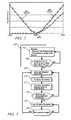
- FIG. 1is a schematic drawing of an exemplary engine system and aftertreatment system in accordance with the present disclosure
- FIG. 2graphically illustrates exemplary test data from a NOx sensor and an ammonia sensor as a function of AFR in accordance with the present disclosure
- FIG. 3is a control scheme for managing an exhaust gas feedstream from the engine in accordance with the present disclosure
- FIG. 4graphically depicts exemplary test data describing a relationship between ammonia production and vehicle speed in accordance with the present disclosure
- FIG. 5graphically depicts exemplary test data describing a relationship between cumulative NOx emissions and vehicle speed in accordance with the present disclosure
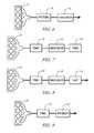
- FIGS. 6-10schematically illustrate additional exemplary configurations of the exhaust aftertreatment system in accordance with the present disclosure
- FIG. 11is a control scheme for managing an exhaust gas feedstream from the engine in accordance with the present disclosure.
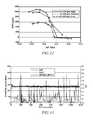
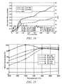
- FIGS. 12-16graphically depict exemplary test data in accordance with the present disclosure.
- FIG. 1schematically shows an internal combustion engine 10 , aftertreatment system 70 , and an accompanying control module 5 that have been constructed in accordance with an embodiment of the disclosure.
- the engine 10is selectively operative at a rich air/fuel ratio (AFR), a stoichiometric AFR, and at an AFR that is primarily lean of stoichiometry.
- AFRrich air/fuel ratio
- stoichiometric AFRstoichiometric AFR
- AFRthat is primarily lean of stoichiometry.
- the disclosurecan be applied to various internal combustion engine systems and combustion cycles.
- the aftertreatment system 70can be connected to the engine 10 that is coupled to an electro-mechanical hybrid powertrain system (not shown).
- the electro-mechanical hybrid powertrain systemcan include torque machines configured to transfer tractive power to a driveline of a vehicle (not shown).
- the exemplary engine 10comprises a multi-cylinder direct-injection four-stroke internal combustion engine having reciprocating pistons 14 slidably movable in cylinders 15 which define variable volume combustion chambers 16 .
- the pistons 14are connected to a rotating crankshaft 12 by which linear reciprocating motion is translated to rotational motion.
- An air intake systemprovides intake air to an intake manifold 29 which directs and distributes air into intake runners of the combustion chambers 16 .
- the air intake systemcomprises airflow ductwork and devices for monitoring and controlling the airflow.
- the air intake devicespreferably include a mass airflow sensor 32 for monitoring mass airflow and intake air temperature.
- a throttle valve 34preferably comprises an electronically controlled device that is used to control airflow to the engine 10 in response to a control signal (ETC) from the control module 5 .
- ETCcontrol signal
- a pressure sensor 36 in the intake manifold 29is configured to monitor manifold absolute pressure and barometric pressure.
- An external flow passagerecirculates exhaust gases from engine exhaust to the intake manifold 29 , having a flow control valve referred to as an exhaust gas recirculation (EGR) valve 38 .
- the control module 5is operative to control mass flow of exhaust gas to the intake manifold 29 by controlling opening of the EGR valve 38 .
- Airflow from the intake manifold 29 into the combustion chamber 16is controlled by one or more intake valve(s) 20 .
- Exhaust flow out of the combustion chamber 16is controlled by one or more exhaust valve(s) 18 to an exhaust manifold 39 .
- the engine 10is equipped with systems to control and adjust openings and closings of the intake and exhaust valves 20 and 18 .
- the openings and closings of the intake and exhaust valves 20 and 18can be controlled and adjusted by controlling intake and exhaust variable cam phasing/variable lift control (VCP/VLC) devices 22 and 24 respectively.
- the intake and exhaust VCP/VLC devices 22 and 24are configured to control and operate an intake camshaft 21 and an exhaust camshaft 23 , respectively.
- the rotations of the intake and exhaust camshafts 21 and 23are linked to and indexed to rotation of the crankshaft 12 , thus linking openings and closings of the intake and exhaust valves 20 and 18 to positions of the crankshaft 12 and the pistons 14 .
- the intake VCP/VLC device 22preferably includes a mechanism configured to switch and control valve lift of the intake valve(s) 20 and variably adjust and control phasing of the intake camshaft 21 for each cylinder 15 in response to a control signal (INTAKE) from the control module 5 .
- the exhaust VCP/VLC device 24preferably comprises a controllable mechanism operative to variably switch and control valve lift of the exhaust valve(s) 18 and variably adjust and control phasing of the exhaust camshaft 23 for each cylinder 15 in response to a control signal (EXHAUST) from the control module 5 .
- the intake and exhaust VCP/VLC devices 22 and 24each preferably includes a controllable two-step variable lift control (VLC) mechanism configured to control magnitude of valve lift, or opening, of the intake and exhaust valve(s) 20 and 18 , respectively, to one of two discrete steps.
- the two discrete stepspreferably include a low-lift valve open position (about 4-6 mm in one embodiment) preferably for load speed, low load operation, and a high-lift valve open position (about 8-13 mm in one embodiment) preferably for high speed and high load operation.
- the intake and exhaust VCP/VLC devices 22 and 24each preferably includes a variable cam phasing (VCP) mechanism to control and adjust phasing (i.e., relative timing) of opening and closing of the intake valve(s) 20 and the exhaust valve(s) 18 respectively.
- VCPvariable cam phasing
- Adjusting the phasingrefers to shifting opening times of the intake and exhaust valve(s) 20 and 18 relative to positions of the crankshaft 12 and the piston 14 in the respective cylinder 15 .
- the VCP mechanisms of the intake and exhaust VCP/VLC devices 22 and 24each preferably has a range of phasing authority of about 60°-90° of crank rotation, thus permitting the control module 5 to advance or retard opening and closing of one of intake and exhaust valve(s) 20 and 18 relative to position of the piston 14 for each cylinder 15 .
- the range of phasing authorityis defined and limited by the intake and exhaust VCP/VLC devices 22 and 24 .
- the intake and exhaust VCP/VLC devices 22 and 24include camshaft position sensors (not shown) to determine rotational positions of the intake and the exhaust camshafts 21 and 23 .
- the VCP/VLC devices 22 and 24are actuated using one of electro-hydraulic, hydraulic, and electric control force, controlled by the control module 5 .
- the engine 10includes a fuel injection system, comprising a plurality of high-pressure fuel injectors 28 each configured to directly inject a mass of fuel into one of the combustion chambers 16 in response to a signal from the control module 5 .
- the fuel injectors 28are supplied pressurized fuel from a fuel distribution system (not shown).
- the engine 10includes a spark-ignition system (not shown) by which spark energy can be provided to a spark plug 26 for igniting or assisting in igniting cylinder charges in each of the combustion chambers 16 in response to a signal (IGN) from the control module 5 .
- a spark-ignition system(not shown) by which spark energy can be provided to a spark plug 26 for igniting or assisting in igniting cylinder charges in each of the combustion chambers 16 in response to a signal (IGN) from the control module 5 .
- the engine 10is equipped with various sensing devices for monitoring engine operation, including a crank sensor 42 having output RPM and operative to monitor crankshaft rotational position, i.e., crank angle and speed, in one embodiment a combustion sensor 30 configured to monitor combustion, and an exhaust gas sensor 40 configured to monitor exhaust gases, comprising an air/fuel ratio sensor in one embodiment.
- the combustion sensor 30comprises a sensor device operative to monitor a state of a combustion parameter and is depicted as a cylinder pressure sensor operative to monitor in-cylinder combustion pressure.
- the output of the combustion sensor 30 and the crank sensor 42are monitored by the control module 5 which determines combustion phasing, i.e., timing of combustion pressure relative to the crank angle of the crankshaft 12 for each cylinder 15 for each combustion cycle.
- the combustion sensor 30can also be monitored by the control module 5 to determine a mean-effective-pressure (IMEP) for each cylinder 15 for each combustion cycle.
- IMEPmean-effective-pressure
- the engine 10 and control module 5are mechanized to monitor and determine states of IMEP for each of the engine cylinders 15 during each cylinder firing event.
- other sensing systemscan be used to monitor states of other combustion parameters within the scope of the disclosure, e.g., ion-sense ignition systems, and non-intrusive cylinder pressure sensors.
- the control module 5executes algorithmic code stored therein to control actuators to control engine operation, including throttle position, spark timing, fuel injection mass and timing, intake and/or exhaust valve timing and phasing, and exhaust gas recirculation valve position to control flow of recirculated exhaust gases.
- Valve timing and phasingmay include negative valve overlap and lift of exhaust valve reopening (in an exhaust re-breathing strategy).
- the control module 5is configured to receive input signals from an operator (e.g., a throttle pedal position and a brake pedal position) to determine an operator torque request and input from the sensors indicating the engine speed and intake air temperature, and coolant temperature and other ambient conditions.
- the control module 5is preferably a general-purpose digital computer generally comprising a microprocessor or central processing unit, storage mediums comprising non-volatile memory including read only memory and electrically programmable read only memory, random access memory, a high speed clock, analog to digital and digital to analog circuitry, and input/output circuitry and devices and appropriate signal conditioning and buffer circuitry.
- the control module 5has a set of control algorithms, comprising resident program instructions and calibrations stored in the non-volatile memory and executed to provide the desired functions.
- the algorithmsare preferably executed during preset loop cycles. Algorithms are executed by the central processing unit and are operable to monitor inputs from the aforementioned sensing devices and execute control and diagnostic routines to control operation of the actuators, using preset calibrations. Loop cycles may be executed at regular intervals, for example each 3.125, 6.25, 12.5, 25 and 100 milliseconds during ongoing engine and vehicle operation. Alternatively, algorithms may be executed in response to occurrence of an event.
- control module 5monitors inputs from the aforementioned sensors to determine states of engine operating parameters.
- the control module 5is configured to receive input signals from an operator (e.g., via a throttle pedal and a brake pedal, not shown) to determine an operator torque request.
- the control module 5monitors the sensors indicating the engine speed and intake air temperature, and coolant temperature and other ambient conditions.
- the control module 5executes algorithmic code stored therein to control the aforementioned actuators to form the cylinder charge, including controlling throttle position, spark-ignition timing, fuel injection mass and timing, EGR valve position to control flow of recirculated exhaust gases, and intake and/or exhaust valve timing and phasing on engines so equipped.
- Valve timing and phasingcan include negative valve overlap (NVO) and lift of exhaust valve reopening (in an exhaust re-breathing strategy) in one embodiment.
- the control module 5can operate to turn the engine 10 on and off during ongoing vehicle operation, and can operate to selectively deactivate a portion of the combustion chambers 15 or a portion of the intake and exhaust valves 20 and 18 through control of fuel and spark and valve deactivation.
- the control module 5can control AFR based upon feedback from the exhaust gas sensor 40 .
- the exhaust gas sensor 40can comprise a wide-range air/fuel ratio sensor configured to generate a linear signal corresponding to air/fuel ratio over an air/fuel ratio range.
- the exhaust gas sensor 40can comprise a switch-type stoichiometric sensor configured to generate an output signal that corresponds to an air/fuel ratio that is one of rich of stoichiometry and lean of stoichiometry.
- the exhaust aftertreatment system 70is fluidly connected to the exhaust manifold 39 and comprises a catalytic device 48 and an ammonia-selective catalytic reduction (NH3-SCR) device 50 .
- the catalytic device 48is fluidly and serially connected upstream of the ammonia-selective catalytic reduction device 50 .
- the catalytic device 48is located in an engine compartment and is close-coupled to the exhaust manifold 39 .
- the NH3-SCR device 50is located in an underfloor location at an extended distance from the catalytic device 48 determined based upon engine and exhaust gas feedstream operating temperatures and other factors.
- the exhaust aftertreatment system 70may include other catalytic and/or trap substrates operative to oxidize, adsorb, desorb, reduce, and combust elements of the exhaust gas feedstream as described herein below.
- the exhaust aftertreatment system 70can be equipped with various sensing devices for monitoring the exhaust gas feedstream from the engine 10 , including a first NOx sensor 49 , a second NOx sensor 52 , and an SCR temperature sensor 51 signally connected to the control module 5 .
- the first and second NOx sensors 49 and 52detect and quantify NOx molecules in the exhaust gas feedstream.
- the first NOx sensor 49detects and quantifies NOx molecules in the exhaust gas feedstream exiting the catalytic device 48 and entering the NH3-SCR device 50 .
- An additional NOx sensor 60may be included in the exhaust aftertreatment system 70 to detect and quantify NOx molecules in the exhaust gas feedstream entering the aftertreatment system 70 .
- only the second NOx sensor 52is included on the aftertreatment system 70 .
- the exemplary engine 10During engine operation, the exemplary engine 10 generates an exhaust gas feedstream containing constituent elements that can be transformed in the aftertreatment system, including hydrocarbons (HC), carbon monoxide (CO), oxides of nitrogen (NOx), and particulate matter (PM), among others.
- Oxygen (O 2 )is present in the exhaust gas feedstream after operating the engine 10 lean of stoichiometry.
- Hydrogen (H 2 ) productioncan occur in the engine 10 through the combustion process. Combustion in a stoichiometric or rich AFR environment, wherein molecular oxygen is scarce, tends to produce elevated levels of molecular hydrogen.
- the catalytic device 48performs a number of catalytic functions for treating an exhaust gas flow.
- the catalytic device 48oxidizes hydrocarbons (HC) and carbon monoxide (CO).
- the catalytic device 48is formulated to produce ammonia during stoichiometric and rich engine operation.
- the formulationmay involve using varying catalysts including platinum group metals, e.g., platinum, palladium, and rhodium, with cerium and zirconium oxides for oxygen storage capacity.
- the catalytic device 48is a three-way catalytic converter configured to oxidize hydrocarbons (HC) and carbon monoxide (CO) and reduce NOx during stoichiometric engine operations.
- the NH3-SCR device 50reduces NOx into other molecules, including nitrogen and water as described hereinbelow.
- An exemplary NH3-SCR device 50includes a substrate (not shown) coated with a zeolite washcoat and catalytic material comprising a catalytically active base metal.
- the substratecomprises a cordierite or metal monolith with a cell density about 62 to 93 cells per square centimeter (400-600 cells per square inch), and a wall thickness about three to seven mils.
- the cells of the substratecomprise flow passages through which exhaust gas flows to contact the catalyst to effect storage of ammonia.
- the substrateis impregnated with the zeolite washcoat.
- the zeolite washcoatalso contains the catalytically active base metals, e.g., iron (Fe), copper (Cu), cobalt (Co), nickel (Ni).
- the catalytically active base metalse.g., iron (Fe), copper (Cu), cobalt (Co), nickel (Ni).
- vanadium-based and/or tungsten (W) on titanium (Ti) compositionsmay be used as catalysts.
- Copper catalystshave been shown to perform effectively at lower temperatures, e.g., 100° C. to 450° C., but have poor thermal durability.
- Iron catalystsmay perform well at higher temperatures, e.g., 200° C. to 650° C., but with decreasing reductant storage capacity.
- the NH3-SCR device 50stores ammonia to reduce NOx emissions.
- the following equationsdescribe the primary reactions with ammonia within the NH3-SCR device 50 : 4NO+4NH 3 +O 2 ⁇ 4N 2 +6H 2 O [1] 3NO 2 +4NH 3 ⁇ 3.5N 2 +6H 2 O [2] 2NO+2NO 2 +4NH 3 ⁇ 4N 2 +6H 2 O [3]
- a methodis disclosed herein to selectively and periodically modulate engine operation to generate an exhaust gas feedstream comprising nitric oxide (NO), carbon monoxide (CO), and hydrogen (H 2 ) to produce ammonia in a catalytic device, such as the catalytic device 48 .
- NOnitric oxide
- COcarbon monoxide
- H 2hydrogen
- Ammoniamay be produced in the catalytic device 48 from a conversion process described by the following equation: NO+CO+1.5H 2 ⁇ NH 3 +CO 2 [4]
- this conversionrequires molecular oxygen to be depleted from the catalytic device 48 before NO will react with the molecular hydrogen. In one embodiment, sufficient conversion occurred at temperatures exceeding 250° C. in the catalytic device 48 . Excess oxygen is frequently present when the internal combustion engine is operated in lean operating modes, with a lean AFR or with excess air. Thus, the control module 5 controls the AFR to a stoichiometric AFR or rich AFR to deplete oxygen in the exhaust gas feedstream when ammonia production in the catalytic device 48 is desired.
- selection of an AFR within the stoichiometric and rich operating rangesfurther facilitates ammonia production, for example, by producing nitric oxide (NO) and hydrogen (H 2 ) in appropriate ratios.
- Eq. 4describes an ideal ratio of 1.5:1 of hydrogen to nitric oxide (H 2 :NO).
- a different actual ratio of hydrogen (H 2 ) to nitric oxide (NO)can produce ammonia.
- a ratio of between 3:1 and 5:1 hydrogen to nitric oxide (H 2 :NO)is preferred in one embodiment.
- Modulating engine operationincludes operating the engine 10 rich or at stoichiometry while meeting the operator torque request and without changing engine output power.
- One exemplary method for operating the exemplary engine 10 rich of stoichiometrycan include executing multiple fuel injection pulses during a combustion cycle including injecting a first fuel pulse into the combustion chamber 16 during each compression stroke. The mass of fuel injected during the first fuel pulse is determined based upon an amount sufficient to operate the engine 10 to meet the operator torque request and other load demands. Subsequent fuel pulses can be injected into the combustion chamber 16 during other strokes of the combustion cycle thereby generating an exhaust gas feedstream comprising nitric oxide (NO), carbon monoxide (CO), and hydrogen (H 2 ) to produce ammonia in the catalytic device 48 . In one embodiment, the subsequent fuel pulses are executed late in a power stroke or early in an exhaust stroke of the combustion cycle thereby minimizing likelihood of combustion in the combustion chamber 16 .
- Ammonia productioncan be controlled or enabled according to a number of factors affecting ammonia usage within the NH3-SCR device 50 , including estimated ammonia storage, estimated or detected ammonia breakthrough, estimated or detected NOx breakthrough downstream from the NH3-SCR device 50 , and engine operation conducive to ammonia production. Monitoring of these factors can be accomplished through monitoring a number of inputs, including engine operation, exhaust gas properties, and NOx conversion efficiency within the NH3-SCR device 50 . For example, the engine 10 produces higher levels of NOx and hydrogen during engine acceleration. Such periods conducive to ammonia production can be utilized to minimize intrusive operation of ammonia production under engine operating conditions less conducive thereto. Periods of modulating engine operation to produce ammonia will vary depending upon required ammonia production, the particulars of the system employed, and the particular operation of the engine 10 .
- FIG. 2graphically illustrates exemplary test data showing signal outputs from a known NOx sensor and a known ammonia sensor as a function of AFR from the engine 10 , illustrative of signal outputs from the first and second NOx sensors 49 and 52 and an ammonia sensor (not shown).
- Known NOx sensing technologiesdo not distinguish between NOx molecules and ammonia molecules in the exhaust gas feedstream.
- signal output from the NOx sensorindicates NOx molecules and increases with increasing AFR. Signal output from the ammonia sensor is minimal.
- FIG. 3shows a control scheme 200 for managing an exhaust gas feedstream from the engine 10 during engine operation.
- the control scheme 200is depicted as a plurality of discrete elements. Such illustration is for ease of description and it should be recognized that the functions performed by these elements may be combined in one or more devices, e.g., implemented in software, hardware, and/or application-specific integrated circuitry.
- the control scheme 200may be executed as one or more algorithms in the control module 5 .
- the control scheme 200includes monitoring the exhaust gas feedstream and the aftertreatment system ( 203 ), including detecting NOx breakthrough and ammonia breakthrough downstream of the NH3-SCR device 50 using the second NOx sensor 52 .
- Monitoring the aftertreatment systemcomprises monitoring temperature of the NH3-SCR device 50 using the SCR temperature sensor 51 .
- the temperature of the NH3-SCR device 50Before initiating lean engine operation or modulating engine operation to produce ammonia, the temperature of the NH3-SCR device 50 must be within a predetermined temperature range ( 206 ).
- the predetermined temperature rangeis 150° C. to 450° C.
- the temperature of the NH3-SCR device 50is monitored continuously using the SCR temperature sensor 51 .
- engine operationmay be controlled to a stoichiometric AFR.
- the control scheme 200modulates engine operation to produce nitric oxide (NO), carbon monoxide (CO), and hydrogen (H 2 ) for ammonia production ( 209 ).
- Ammoniais produced in the catalytic device 48 as described hereinabove using the nitric oxide (NO), carbon monoxide (CO), and hydrogen (H 2 ) ( 212 ) and transferred downstream to the NH3-SCR device 50 for storage ( 215 ).
- the control scheme 200can adjust engine operation to discontinue ammonia production subsequent to determining the NH3-SCR device 50 is saturated with ammonia ( 218 ).
- Ammonia productioncan also be discontinued after a predetermined threshold of ammonia molecules are generated or when engine operating conditions are not conducive to ammonia production, e.g., during vehicle decelerations, engine idling, or engine stops.
- Ammonia saturationmay be estimated based upon a predetermined elapsed time, or by monitoring the exhaust gas feedstream downstream of the NH3-SCR device 50 to detect ammonia breakthrough, or determined after executing a predetermined number of cylinder events.
- Ammonia breakthroughmay be detected by monitoring signal output of an ammonia sensor (not shown) configured to monitor the exhaust gas feedstream downstream of the NH3-SCR device 50 .
- Another method for detecting ammonia breakthroughcomprises monitoring the second NOx sensor 52 .
- signal output from the second NOx sensor 52increases, indicate ammonia breakthrough.
- saturationmay be estimated using a model according to methods sufficient to accurately estimate operation of the combustion cycle, aftertreatment processes, conversions, and monitored operating conditions including intake mass airflow, AFR, engine speed, TWC temperature, TWC aging state, SCR device temperature, and SCR device aging state.
- the modelmay be calibrated according to test results corresponding to a particular hardware application.
- the control scheme 200discontinues modulating engine operation and ammonia production and transitions engine operation to lean engine operation ( 221 ), resulting in increased NOx emissions into the exhaust gas flow.
- the catalytic device 48reduces a portion of the NOx emissions transferring oxygen and nitrogen downstream to the NH3-SCR device 50 .
- Ammonia stored on the catalyst of the NH3-SCR device 50reacts with NOx entering the NH3-SCR device 50 thereby reducing NOx emissions and producing nitrogen and water.
- the stored ammoniais depleted as ammonia molecules react with NOx molecules. When the ammonia on the catalyst of the NH3-SCR device 50 is depleted, NOx emissions pass through the NH3-SCR device 50 unprocessed.
- the control scheme 200preferably discontinues lean engine operation after detecting NOx breakthrough downstream from the NH3-SCR device 50 ( 224 ).
- An increase in signal output from the second NOx sensor 52is correlatable to an increase in NOx emissions out of the NH3-SCR device 50 during lean engine operation, and indicates NOx breakthrough.
- Another method for detecting NOx breakthroughcomprises modeling ammonia depletion. Ammonia depletion and therefore NOx breakthrough may be estimated using a model according to methods sufficient to accurately estimate operation of the combustion cycle, aftertreatment processes, conversions, and monitored operating conditions including intake mass airflow, AFR, engine speed, TWC temperature, TWC aging state, SCR device temperature, and SCR device aging state. The model may be calibrated according to test results corresponding to a particular hardware application. After determining that ammonia is depleted or detecting NOx breakthrough, the control scheme 200 may modulate engine operation to produce ammonia ( 209 ).
- FIG. 4graphically depicts exemplary test data describing a relationship between ammonia production and vehicle speeds.
- Ammonia concentrationswere measured with a Fourier-transform infrared spectrometer during engine operations using the exemplary aftertreatment system 70 .
- FIG. 4shows, during engine accelerations, when the exemplary engine 10 operates at stoichiometry or slightly rich of stoichiometry (e.g., AFR between 13.8:1 and 14.2:1), ammonia concentrations produced by the catalytic device 48 can increase.
- FIG. 5graphically depicts exemplary test data depicting a relationship between cumulative NOx emissions out of the exemplary engine 10 , catalytic device 48 , and the NH3-SCR device 50 and vehicle speed.
- FIG. 5also depicts a NOx reduction by the NH3-SCR device 50 after NOx reduction in the catalytic device 48 .
- FIG. 6shows an engine 10 and an exhaust aftertreatment system including a particulate filter combined with a TWC (PF/TWC) 48 upstream of the NH3-SCR device 50 .
- FIG. 7shows an engine 10 and an exhaust aftertreatment system including a first TWC 48 upstream of the NH3-SCR device 50 and a second TWC 48 ′ downstream of the NH3-SCR device 50 .
- the second TWC 48 ′ downstream of the NH3-SCR device 50may comprise an oxidation catalyst for managing NH3 breakthrough.
- FIG. 8shows an engine 10 and an exhaust aftertreatment configuration including a TWC 48 , a SCR device 50 (NH3-SCR) and a NOx adsorber device 100 (LNT) downstream of the NH3-SCR device 50 .
- FIG. 9shows an engine 10 and an exhaust aftertreatment configuration including a TWC 48 , and a NH3-SCR device combined with a particulate filter 50 ′.
- FIG. 10shows another embodiment including an engine 10 ′ and an exhaust aftertreatment configuration including a close-coupled TWC 48 and an underfloor converter including a second TWC 48 ′ coupled to a NH3-SCR device 50 .
- the engine 10 ′preferably comprises a port-fuel injection engine that injects fuel into runners of an intake manifold upstream of each combustion chamber (not shown).
- the engine 10 ′is controlled to operate at or about stoichiometry within a narrowly controlled band for +/ ⁇ AFR about stoichiometry which can be an air/fuel ratio band of 14.6:1+/ ⁇ 0.05 in one embodiment.
- FIG. 11shows a second control scheme 200 ′ comprising a method for managing an exhaust gas feedstream from the embodiment described with reference to FIG. 10 comprising the port-fuel injection engine 10 ′ and the aftertreatment system comprising the TWC 48 and the NH3-SCR device 50 during engine operations, with like elements identified using like numerals.
- the embodiment described in FIG. 10includes an engine-out exhaust gas sensor, a first NOx sensor upstream of the NH3-SCR device 50 , a second NOx sensor downstream of the NH3-SCR device 50 , and a temperature sensor configured to monitor temperature of the NH3-SCR device 50 .
- the control scheme 200 ′comprises monitoring the exhaust gas feedstream and the aftertreatment system ( 203 ).
- Monitoring the exhaust gas feedstreamincludes detecting NOx breakthrough and ammonia breakthrough downstream of the NH3-SCR device 50 using the second NOx sensor.
- Monitoring the aftertreatment systemcan include monitoring temperature of the NH3-SCR device 50 using the SCR temperature sensor.
- the temperature of the NH3-SCR device 50is preferably within a predetermined temperature range that corresponds to the specific catalytic material comprising a catalytically active base metal that is used in the NH3-SCR device 50 ( 206 ). In one embodiment the predetermined temperature range is 150° C. to 450° C. for the NH3-SCR device 50 .
- the temperature of the NH3-SCR device 50is monitored continuously using the SCR temperature sensor.
- engine operationis preferably at or near stoichiometry.
- engine operationis controlled to prevent operation in a fuel cutoff mode, e.g., during decelerations, and prevent autonomic engine stops.
- FIG. 12shows ammonia production (NH3) corresponding to engine-out air/fuel ratio (A/F Ratio) in the exhaust gas feedstream downstream of a close-coupled three-way catalytic converter for an exemplary system at several engine loads (Low, Medium, High) at a predetermined engine operating speed (1000 rpm).
- NH3ammonia production
- A/F Ratioengine-out air/fuel ratio
- resultsfurther indicate that there is some ammonia production during stoichiometric operation when the engine-out air/fuel ratio oscillates rich and lean of stoichiometry, including when the air/fuel ratio oscillates rich and lean of stoichiometry with an expanded band for +/ ⁇ AFR about stoichiometry.
- the control scheme 200 ′modulates engine operation to produce the nitric oxide (NO), carbon monoxide (CO), and hydrogen (H 2 ) for ammonia production ( 209 ′).
- modulating engine operationmay include operating the engine 10 ′ at stoichiometry, operating the engine 10 ′ at stoichiometry with an expanded band for +/ ⁇ AFR about stoichiometry, e.g., 14.6:1+/ ⁇ 0.2 in one embodiment, and operating the engine 10 ′ at or about an air/fuel ratio of 14:1, depending upon an anticipated need for ammonia.
- engine operationcan be adjusted to discontinue modulating engine operation to ammonia production ( 221 ′). This includes responding to commands for engine operating conditions that are not conducive to ammonia production, including fuel cutoff events, e.g., during deceleration events and engine stopping, and transitioning engine operation to lean engine operation.
- the control scheme 200 ′discontinues modulating engine operation to produce ammonia when the NH3-SCR 50 saturates, and transitions engine operation to lean engine operation resulting in increased NOx emissions into the exhaust gas feedstream.
- Lean engine operationcan include operating at an air/fuel ratio of about 16.0:1.
- the stored ammoniais depleted as ammonia molecules react with NOx molecules.
- the engine 10 ′may be commanded to operate lean of stoichiometry in response to engine and vehicle operation, including fuel cutoff events, e.g., during deceleration events, engine idling, and engine stopping events, as can occur with engine stop/start systems associated with hybrid powertrain system operation.
- the control scheme 200 ′preferably discontinues lean engine operation after detecting NOx breakthrough downstream from the NH3-SCR device 50 ( 224 ). After determining that ammonia is depleted or detecting NOx breakthrough, the control scheme 200 ′ may modulate engine operation to produce ammonia ( 209 ′).
- FIG. 13graphically shows engine-out air/fuel ratio (A/F), vehicle speed (MPH), and ammonia generation (NH3) over a series of acceleration and deceleration events for an exemplary vehicle including an engine 10 ′ and aftertreatment system configured as described with reference to FIG. 10 , with the engine 10 ′ operating at stoichiometry.
- the series of acceleration and deceleration eventsare analogous to an FTP-18 driving cycle. The results indicate a substantial amount of ammonia being produced during stoichiometric engine operation.
- FIG. 14graphically shows vehicle speed (MPH), and NOx emissions into and out of the NH3-SCR device 50 which comprises an Fe-SCR device over a series of acceleration and deceleration events for an exemplary vehicle including an exemplary engine 10 and aftertreatment system, with the engine 10 operating at stoichiometry.
- the series of acceleration and deceleration eventsare analogous to an FTP-18 driving cycle.
- the resultsindicate a reduction in NOx emissions across the NH3-SCR device in the presence of ammonia produced during stoichiometric engine operation.
- FIG. 15graphically shows NOx conversion efficiency (%) corresponding to temperature across an NH3-SCR device using copper as the catalytic material.
- the resultsindicate that there is low conversion efficiency when there is no oxygen (O 2 ) present, but that with low levels of oxygen, e.g., 0.5% concentration in the feedstream, the conversion efficiency increased substantially, including conversion efficiency in excess of 80% at 0.5% oxygen concentration in the feedstream when the temperature was at or above 350° C.
- FIG. 16graphically shows NOx conversion efficiency (%) corresponding to temperature across an NH3-SCR device using iron as the catalytic material.
- the resultsindicate that there is low conversion efficiency when there is no oxygen (O 2 ) present, but that with low levels of oxygen concentration in the feedstream, e.g., 0.05% or 500 ppm, the conversion efficiency increased substantially, including a conversion efficiency in excess of 60% at 0.05% oxygen concentration in the feedstream when the temperature was at or above 350° C.
- the results of FIGS. 15 and 16indicate that there can be substantial NOx conversion at exhaust gas feedstream conditions having low levels of oxygen, e.g., as occurs at stoichiometric engine operation.
- the method described hereincontemplates production of ammonia through engine modulation, utilizing components of the exhaust gas feedstream to sustain aftertreatment of NOx in an SCR device. It will be appreciated that these methods can be used in isolation from urea injection, with the methods described supplying all of the required ammonia. Alternatively, the methods described herein can be used to complement a urea injection system, extending the range of the system between required filling of a urea storage tank while allowing a full range of engine and powertrain operation without significant monitoring of ammonia production cycles and ammonia storage capacity, due to available urea injection on demand.
Landscapes
- Engineering & Computer Science (AREA)
- Chemical & Material Sciences (AREA)
- Combustion & Propulsion (AREA)
- General Engineering & Computer Science (AREA)
- Mechanical Engineering (AREA)
- Chemical Kinetics & Catalysis (AREA)
- Health & Medical Sciences (AREA)
- Biomedical Technology (AREA)
- Oil, Petroleum & Natural Gas (AREA)
- General Chemical & Material Sciences (AREA)
- Analytical Chemistry (AREA)
- Environmental & Geological Engineering (AREA)
- Toxicology (AREA)
- Materials Engineering (AREA)
- Computer Networks & Wireless Communication (AREA)
- Signal Processing (AREA)
- Exhaust Gas After Treatment (AREA)
- Exhaust Gas Treatment By Means Of Catalyst (AREA)
Abstract
Description
4NO+4NH3+O2→4N2+6H2O [1]
3NO2+4NH3→3.5N2+6H2O [2]
2NO+2NO2+4NH3→4N2+6H2O [3]
NO+CO+1.5H2→NH3+CO2 [4]
Claims (21)
Priority Applications (4)
| Application Number | Priority Date | Filing Date | Title |
|---|---|---|---|
| US12/430,819US8381512B2 (en) | 2008-05-02 | 2009-04-27 | Passive ammonia-selective catalytic reduction for NOx control in internal combustion engines |
| US12/576,412US8393140B2 (en) | 2008-05-02 | 2009-10-09 | Passive ammonia-selective catalytic reduction for NOx control in internal combustion engines |
| DE102009054046.6ADE102009054046B4 (en) | 2008-11-24 | 2009-11-20 | Method for operating an internal combustion engine and engine control system |
| US13/049,973US9180408B2 (en) | 2008-05-02 | 2011-03-17 | Fuel efficient ammonia generation strategy for lean-burn engines utilizing passive NH3-SCR for the control of NOx |
Applications Claiming Priority (2)
| Application Number | Priority Date | Filing Date | Title |
|---|---|---|---|
| US4980408P | 2008-05-02 | 2008-05-02 | |
| US12/430,819US8381512B2 (en) | 2008-05-02 | 2009-04-27 | Passive ammonia-selective catalytic reduction for NOx control in internal combustion engines |
Related Child Applications (2)
| Application Number | Title | Priority Date | Filing Date |
|---|---|---|---|
| US12/576,412Continuation-In-PartUS8393140B2 (en) | 2008-05-02 | 2009-10-09 | Passive ammonia-selective catalytic reduction for NOx control in internal combustion engines |
| US13/049,973Continuation-In-PartUS9180408B2 (en) | 2008-05-02 | 2011-03-17 | Fuel efficient ammonia generation strategy for lean-burn engines utilizing passive NH3-SCR for the control of NOx |
Publications (2)
| Publication Number | Publication Date |
|---|---|
| US20100107605A1 US20100107605A1 (en) | 2010-05-06 |
| US8381512B2true US8381512B2 (en) | 2013-02-26 |
Family
ID=41255740
Family Applications (1)
| Application Number | Title | Priority Date | Filing Date |
|---|---|---|---|
| US12/430,819Expired - Fee RelatedUS8381512B2 (en) | 2008-05-02 | 2009-04-27 | Passive ammonia-selective catalytic reduction for NOx control in internal combustion engines |
Country Status (4)
| Country | Link |
|---|---|
| US (1) | US8381512B2 (en) |
| CN (1) | CN102084096B (en) |
| DE (1) | DE112009001034T5 (en) |
| WO (1) | WO2009134831A2 (en) |
Cited By (8)
| Publication number | Priority date | Publication date | Assignee | Title |
|---|---|---|---|---|
| US20120316754A1 (en)* | 2011-06-09 | 2012-12-13 | GM Global Technology Operations LLC | Method for operating a spark-ignition, direct-injection internal combustion engine |
| US9663366B2 (en) | 2012-03-05 | 2017-05-30 | Basf Se | Ammonia oxidation reactor with internal filter element |
| US9957911B2 (en) | 2016-02-18 | 2018-05-01 | GM Global Technology Operations LLC | Dedicated exhaust gas recirculation control systems and methods |
| WO2018136731A1 (en)* | 2017-01-20 | 2018-07-26 | Tenneco Automotive Operating Company Inc. | Method for urea conversion efficiency measurement |
| US10077727B2 (en) | 2016-01-13 | 2018-09-18 | GM Global Technology Operations LLC | Engine control systems and methods for nitrogen oxide reduction |
| US10519883B2 (en) | 2018-06-01 | 2019-12-31 | GM Global Technology Operations LLC | Catalyst temperature maintenance systems and methods |
| US20200248607A1 (en)* | 2019-01-31 | 2020-08-06 | Hyundai Motor Company | After treatment system and after treatment method for lean-burn engine |
| US11686236B1 (en) | 2022-02-18 | 2023-06-27 | Saudi Arabian Oil Company | Device for the reduction of ammonia and nitrogen oxides emissions |
Families Citing this family (45)
| Publication number | Priority date | Publication date | Assignee | Title |
|---|---|---|---|---|
| US9180408B2 (en)* | 2008-05-02 | 2015-11-10 | GM Global Technology Operations LLC | Fuel efficient ammonia generation strategy for lean-burn engines utilizing passive NH3-SCR for the control of NOx |
| US8931257B2 (en) | 2009-02-23 | 2015-01-13 | GM Global Technology Operations LLC | Technique for production of ammonia on demand in a three way catalyst for a passive selective catalytic reduction system |
| JP4894954B2 (en)* | 2009-10-06 | 2012-03-14 | トヨタ自動車株式会社 | Exhaust gas purification system for internal combustion engine |
| EP2354485A1 (en)* | 2010-01-13 | 2011-08-10 | Delphi Technologies Holding S.à.r.l. | Exhaust system for compression-ignition engine |
| US9008944B2 (en) | 2010-05-24 | 2015-04-14 | GM Global Technology Operations LLC | Method and apparatus for controlling operation of an internal combustion engine operating in HCCI combustion mode |
| US8645044B2 (en) | 2010-05-24 | 2014-02-04 | GM Global Technology Operations LLC | Method and apparatus for operating an internal combustion engine in a homogeneous-charge compression-ignition combustion mode |
| US8616182B2 (en) | 2010-05-24 | 2013-12-31 | GM Global Technology Operations LLC | Method and apparatus for controlling an internal combustion engine coupled to a passive selective catalytic reduction aftertreatment system |
| US9242242B2 (en) | 2010-09-02 | 2016-01-26 | Basf Se | Catalyst for gasoline lean burn engines with improved NO oxidation activity |
| US8950174B2 (en) | 2010-09-02 | 2015-02-10 | Basf Se | Catalysts for gasoline lean burn engines with improved NH3-formation activity |
| EP2611536B1 (en) | 2010-09-02 | 2022-05-25 | Basf Se | Catalyst for gasoline lean burn engines with improved nh3-formation activity |
| FR2966870B1 (en)* | 2010-10-27 | 2016-02-19 | Peugeot Citroen Automobiles Sa | DEVICE FOR TREATING GAS ENGINE EXHAUST GAS WITH PARTICLE FILTER, EXHAUST LINE AND CORRESPONDING VEHICLE |
| US8661788B2 (en)* | 2010-12-29 | 2014-03-04 | GM Global Technology Operations LLC | Exhaust aftertreatment systems that include an ammonia-SCR catalyst promoted with an oxygen storage material |
| FR2971810B1 (en)* | 2011-02-18 | 2013-03-15 | Peugeot Citroen Automobiles Sa | EXHAUST GAS POST-TREATMENT ASSEMBLY OF A SUPERCHARGED COMBUSTION ENGINE, AND MOTOR VEHICLE COMPRISING SUCH AN ASSEMBLY |
| DE102011017486A1 (en)* | 2011-04-19 | 2012-10-25 | Daimler Ag | Operating method for a motor vehicle diesel engine with an emission control system |
| US8800274B2 (en) | 2011-05-12 | 2014-08-12 | GM Global Technology Operations LLC | Method for managing ammonia slip |
| US8919099B2 (en)* | 2011-06-10 | 2014-12-30 | GM Global Technology Operations LLC | System and method for determining an ammonia generation rate in a three-way catalyst |
| US20130019589A1 (en)* | 2011-07-19 | 2013-01-24 | GM Global Technology Operations LLC | Exhaust aftertreatment system for compression-ignition engines |
| US9714625B2 (en) | 2011-07-28 | 2017-07-25 | GM Global Technology Operations LLC | System and method for controlling ammonia levels in a selective catalytic reduction catalyst using a nitrogen oxide sensor |
| DE102011111590A1 (en) | 2011-08-25 | 2013-02-28 | Volkswagen Aktiengesellschaft | Exhaust gas treatment device, process for the treatment of exhaust gas and motor vehicle |
| US8769932B2 (en)* | 2011-10-13 | 2014-07-08 | GM Global Technology Operations LLC | Cold start NO2 generation system |
| US8918265B2 (en) | 2012-01-18 | 2014-12-23 | GM Global Technology Operations LLC | Method and apparatus for controlling operation of an internal combustion engine operating in HCCI combustion mode |
| US9138686B2 (en) | 2012-03-30 | 2015-09-22 | GM Global Technology Operations LLC | Carbon monoxide-selective oxidation catalysts |
| US9188071B2 (en) | 2012-05-15 | 2015-11-17 | GM Global Technology Operations LLC | System and method for controlling an engine based on ammonia storage in multiple selective catalytic reduction catalysts |
| US9528462B2 (en)* | 2012-06-15 | 2016-12-27 | GM Global Technology Operations LLC | NOx sensor plausibility monitor |
| WO2014003752A1 (en)* | 2012-06-28 | 2014-01-03 | International Engine Intellectual Property Company, Llc | Ammonia abatement system for exhaust systems |
| US9512793B2 (en) | 2012-10-16 | 2016-12-06 | GM Global Technology Operations LLC | Combustion driven ammonia generation strategies for passive ammonia SCR system |
| DE102013000013A1 (en)* | 2013-01-02 | 2014-07-03 | Thyssenkrupp Industrial Solutions Gmbh | Elimination of ammonia and lower alkanes and / or hydrogen in waste gas streams in industrial plants |
| US9657626B2 (en)* | 2015-05-18 | 2017-05-23 | Ford Global Technologies, Llc | Emissions reduction system |
| JP6350444B2 (en)* | 2015-08-10 | 2018-07-04 | トヨタ自動車株式会社 | Exhaust gas purification device for internal combustion engine |
| DE102017100518A1 (en)* | 2016-02-04 | 2017-08-10 | Umicore Ag & Co. Kg | System and process for exhaust gas purification while avoiding nitrous oxide |
| US20170254240A1 (en)* | 2016-03-03 | 2017-09-07 | International Engine Intellectual Property Company, Llc | Limiting nox emissions using two catalysts |
| KR101974331B1 (en)* | 2016-08-03 | 2019-05-02 | 바르실라 핀랜드 오이 | Internal combustion engine with cooled internal exhaust gas recirculation and SCR catalyst |
| KR102471297B1 (en)* | 2016-10-24 | 2022-11-29 | 바스프 코포레이션 | Integrated SCR catalyst and LNT for NOx reduction |
| CN106807211A (en)* | 2016-12-28 | 2017-06-09 | 神华集团有限责任公司 | Prevent the oxidation net and SCR denitration device of the escaping of ammonia |
| EP3536921B1 (en)* | 2018-03-07 | 2020-12-23 | Crmt | A system and method for accurately measuring nox and nh3 contents in exhaust fumes |
| JP6988648B2 (en)* | 2018-03-30 | 2022-01-05 | トヨタ自動車株式会社 | Exhaust purification device for internal combustion engine |
| WO2019207333A1 (en)* | 2018-04-27 | 2019-10-31 | Carrier Corporation | Exhaust back pressure and temperature monitoring transport refrigeration unit |
| CN109162819A (en)* | 2018-08-14 | 2019-01-08 | 北京理工大学 | A kind of combined type after-treatment device suitable for hydrogen internal combustion engine |
| CN109162789B (en)* | 2018-09-26 | 2020-08-21 | 潍柴动力股份有限公司 | An automobile exhaust gas treatment system |
| US10982578B2 (en)* | 2019-01-31 | 2021-04-20 | Hyundai Motor Company | CO clean-up catalyst, after treatment system and after treatment method |
| US10697340B1 (en)* | 2019-01-31 | 2020-06-30 | Hyundai Motor Company | After treatment system and after treatment method for lean-burn engine |
| US11073057B2 (en)* | 2019-01-31 | 2021-07-27 | Hyundai Motor Company | Co clean-up catalyst, after treatment system and after treatment method |
| FR3107556B1 (en)* | 2020-02-25 | 2023-03-03 | Psa Automobiles Sa | EXHAUST GAS DEPOLLUTION SYSTEM FOR A PETROL ENGINE |
| US11698034B2 (en)* | 2021-04-13 | 2023-07-11 | GM Global Technology Operations LLC | Method of transient control for robust enrichment operation in low temperature combustion engine |
| CN115596540B (en)* | 2022-10-28 | 2025-04-29 | 溢普科技(佛山)有限责任公司 | A post-treatment device and post-treatment control method for an ammonia internal combustion engine |
Citations (15)
| Publication number | Priority date | Publication date | Assignee | Title |
|---|---|---|---|---|
| US5782087A (en)* | 1995-11-10 | 1998-07-21 | Toyota Jidosha Kabushiki Kaisha | Device for purifying exhaust gas of an engine |
| US6047542A (en) | 1995-11-17 | 2000-04-11 | Toyota Jidosha Kabushiki Kaisha | Method and device for purifying exhaust gas of engine |
| US6109024A (en)* | 1997-05-12 | 2000-08-29 | Toyota Jidosha Kabushiki Kaisha | Exhaust gas purification device for an internal combustion engine |
| US6361754B1 (en)* | 1997-03-27 | 2002-03-26 | Clean Diesel Technologies, Inc. | Reducing no emissions from an engine by on-demand generation of ammonia for selective catalytic reduction |
| US20020129600A1 (en)* | 1999-02-19 | 2002-09-19 | Mitsubishi Jidosha Kogyo Kabushiki Kaisha | Cylinder injection type internal combustion engine |
| US20050129601A1 (en) | 2003-11-04 | 2005-06-16 | Engelhard Corporation | Emissions treatment system with NSR and SCR catalysts |
| DE102005022420A1 (en)* | 2005-05-14 | 2006-06-14 | Daimlerchrysler Ag | Exhaust gas recycling plant for burning device in motor vehicle, comprises a selective catalytic reduction catalyst in track, reduction device, control unit operates the burning device, oxidation catalyst, and a particle filter |
| US7063642B1 (en) | 2005-10-07 | 2006-06-20 | Eaton Corporation | Narrow speed range diesel-powered engine system w/ aftertreatment devices |
| US20070092426A1 (en)* | 2005-10-03 | 2007-04-26 | Josh Driscoll | On-board ammonia generation and exhaust after treatment system using same |
| US20070157608A1 (en)* | 2002-10-22 | 2007-07-12 | Ford Global Technologies, Llc | Catalyst System for the Reduction of NOx and NH3 Emissions |
| US20080026932A1 (en) | 2006-07-31 | 2008-01-31 | Honda Motor Co. | NOx purifying catalyst |
| US20080041040A1 (en)* | 2006-08-16 | 2008-02-21 | Doring Andreas | Exhaust gas post treatment system |
| US20080053071A1 (en) | 2006-09-05 | 2008-03-06 | Karen Adams | System and Method for Reducing NOx Emissions |
| US20080089820A1 (en) | 2005-06-03 | 2008-04-17 | Emitec Gesellschaft Für Emissionstechnologie Mbh | Method and Device for Providing Ammonia in an Exhaust Gas Flow of an Internal Combustion Engine |
| US20080102010A1 (en) | 2005-06-03 | 2008-05-01 | Emitec Gesellschaft Fur Emissionstechnologie Mbh | Method and Device for Treating Exhaust Gases of Internal Combustion Engines |
Family Cites Families (1)
| Publication number | Priority date | Publication date | Assignee | Title |
|---|---|---|---|---|
| JP4494961B2 (en)* | 2002-04-23 | 2010-06-30 | トムソン ライセンシング | Method and apparatus for controlling video signal processing apparatus |
- 2009
- 2009-04-27USUS12/430,819patent/US8381512B2/ennot_activeExpired - Fee Related
- 2009-04-29WOPCT/US2009/042020patent/WO2009134831A2/enactiveApplication Filing
- 2009-04-29CNCN200980125681.1Apatent/CN102084096B/ennot_activeExpired - Fee Related
- 2009-04-29DEDE112009001034Tpatent/DE112009001034T5/ennot_activeCeased
Patent Citations (15)
| Publication number | Priority date | Publication date | Assignee | Title |
|---|---|---|---|---|
| US5782087A (en)* | 1995-11-10 | 1998-07-21 | Toyota Jidosha Kabushiki Kaisha | Device for purifying exhaust gas of an engine |
| US6047542A (en) | 1995-11-17 | 2000-04-11 | Toyota Jidosha Kabushiki Kaisha | Method and device for purifying exhaust gas of engine |
| US6361754B1 (en)* | 1997-03-27 | 2002-03-26 | Clean Diesel Technologies, Inc. | Reducing no emissions from an engine by on-demand generation of ammonia for selective catalytic reduction |
| US6109024A (en)* | 1997-05-12 | 2000-08-29 | Toyota Jidosha Kabushiki Kaisha | Exhaust gas purification device for an internal combustion engine |
| US20020129600A1 (en)* | 1999-02-19 | 2002-09-19 | Mitsubishi Jidosha Kogyo Kabushiki Kaisha | Cylinder injection type internal combustion engine |
| US20070157608A1 (en)* | 2002-10-22 | 2007-07-12 | Ford Global Technologies, Llc | Catalyst System for the Reduction of NOx and NH3 Emissions |
| US20050129601A1 (en) | 2003-11-04 | 2005-06-16 | Engelhard Corporation | Emissions treatment system with NSR and SCR catalysts |
| DE102005022420A1 (en)* | 2005-05-14 | 2006-06-14 | Daimlerchrysler Ag | Exhaust gas recycling plant for burning device in motor vehicle, comprises a selective catalytic reduction catalyst in track, reduction device, control unit operates the burning device, oxidation catalyst, and a particle filter |
| US20080089820A1 (en) | 2005-06-03 | 2008-04-17 | Emitec Gesellschaft Für Emissionstechnologie Mbh | Method and Device for Providing Ammonia in an Exhaust Gas Flow of an Internal Combustion Engine |
| US20080102010A1 (en) | 2005-06-03 | 2008-05-01 | Emitec Gesellschaft Fur Emissionstechnologie Mbh | Method and Device for Treating Exhaust Gases of Internal Combustion Engines |
| US20070092426A1 (en)* | 2005-10-03 | 2007-04-26 | Josh Driscoll | On-board ammonia generation and exhaust after treatment system using same |
| US7063642B1 (en) | 2005-10-07 | 2006-06-20 | Eaton Corporation | Narrow speed range diesel-powered engine system w/ aftertreatment devices |
| US20080026932A1 (en) | 2006-07-31 | 2008-01-31 | Honda Motor Co. | NOx purifying catalyst |
| US20080041040A1 (en)* | 2006-08-16 | 2008-02-21 | Doring Andreas | Exhaust gas post treatment system |
| US20080053071A1 (en) | 2006-09-05 | 2008-03-06 | Karen Adams | System and Method for Reducing NOx Emissions |
Non-Patent Citations (17)
| Title |
|---|
| About.com, "Port Fuel Injection", archived Sep. 17, 2005.* |
| Joseph R. Theis "Selective Catalytic Reduction for Treating the NOx Emissions from Lean-Burn Gasoline Engines: Durability Assessment" SAE Technical Paper Series, Detroit, MI, USA. |
| Joseph R. Theis "Selective Catalytic Reduction for Treating the NOx Emissions from Lean-Burn Gasoline Engines: Performance Assessment" SAE Technical Paper Series, Detroit, MI, USA. |
| Keppeler et al., English Abstract of DE 102005022420 A1; Jun. 14, 2006.* |
| Keppeler et al., Machine Translation of DE 102005022420 A1; Jun. 14, 2006.* |
| Nakahira, T.,"Catalytic Engine" NOx Reduction of Diesel Engines with New Concept Onboard Ammonia Synthesis System; SAE Technical Paper Series; Feb. 1992; SAE 920469. |
| Ogunwumi, S.; In-Situ NH3 Generation for SCR NOx Applications; SAE Technical Paper Series; Oct. 2002; SAE 2002-01-2872. |
| Tadao Nakatsuji "A NOx Reduction system using ammonia-storage selective catalytic reduction in rich/lean excursions" Science Direct, Jul. 27, 2007. |
| U.S. Appl. No. 12/329,162, Perry, et al. |
| U.S. Appl. No. 12/330,587, Najt, et al. |
| U.S. Appl. No. 12/360,901, Perry, et al. |
| U.S. Appl. No. 12/360,901. Title: Technique for Production of Ammonia on Demand in a Three Way Catalyst for a Passive Selective Catalytic Reduction System. First Inventor: Kevin L. Perry. |
| U.S. Appl. No. 12/360,908, Najt, et al. |
| U.S. Appl. No. 12/390,588, Narayanaswamy, et al. |
| U.S. Appl. No. 12/576,412, Perry, et al. |
| U.S. Appl. No. 12/624,709, Li, et al. |
| U.S. Appl. No. 61/117,269. Title: Technique for Production of Ammonia on Demand in a Three Way Catalyst for a Passive Selective Catalytic Reduction System. First Inventor: Kevin L. Perry. |
Cited By (11)
| Publication number | Priority date | Publication date | Assignee | Title |
|---|---|---|---|---|
| US20120316754A1 (en)* | 2011-06-09 | 2012-12-13 | GM Global Technology Operations LLC | Method for operating a spark-ignition, direct-injection internal combustion engine |
| US9046051B2 (en)* | 2011-06-09 | 2015-06-02 | GM Global Technology Operations LLC | Method for operating a spark-ignition, direct-injection internal combustion engine |
| US9663366B2 (en) | 2012-03-05 | 2017-05-30 | Basf Se | Ammonia oxidation reactor with internal filter element |
| US10077727B2 (en) | 2016-01-13 | 2018-09-18 | GM Global Technology Operations LLC | Engine control systems and methods for nitrogen oxide reduction |
| US9957911B2 (en) | 2016-02-18 | 2018-05-01 | GM Global Technology Operations LLC | Dedicated exhaust gas recirculation control systems and methods |
| WO2018136731A1 (en)* | 2017-01-20 | 2018-07-26 | Tenneco Automotive Operating Company Inc. | Method for urea conversion efficiency measurement |
| US10400647B2 (en) | 2017-01-20 | 2019-09-03 | Tenneco Automotive Operating Company Inc. | Method for urea conversion efficiency measurement |
| US10519883B2 (en) | 2018-06-01 | 2019-12-31 | GM Global Technology Operations LLC | Catalyst temperature maintenance systems and methods |
| US20200248607A1 (en)* | 2019-01-31 | 2020-08-06 | Hyundai Motor Company | After treatment system and after treatment method for lean-burn engine |
| US10808588B2 (en)* | 2019-01-31 | 2020-10-20 | Hyundai Motor Company | After treatment system and after treatment method for lean-burn engine |
| US11686236B1 (en) | 2022-02-18 | 2023-06-27 | Saudi Arabian Oil Company | Device for the reduction of ammonia and nitrogen oxides emissions |
Also Published As
| Publication number | Publication date |
|---|---|
| US20100107605A1 (en) | 2010-05-06 |
| CN102084096A (en) | 2011-06-01 |
| DE112009001034T5 (en) | 2011-06-09 |
| WO2009134831A2 (en) | 2009-11-05 |
| CN102084096B (en) | 2014-10-29 |
| WO2009134831A3 (en) | 2010-01-07 |
Similar Documents
| Publication | Publication Date | Title |
|---|---|---|
| US8381512B2 (en) | Passive ammonia-selective catalytic reduction for NOx control in internal combustion engines | |
| US8302379B2 (en) | Passive ammonia-selective catalytic reduction for NOx control in internal combustion engines | |
| US8393140B2 (en) | Passive ammonia-selective catalytic reduction for NOx control in internal combustion engines | |
| US9180408B2 (en) | Fuel efficient ammonia generation strategy for lean-burn engines utilizing passive NH3-SCR for the control of NOx | |
| US8443587B2 (en) | Method for exhaust aftertreatment in an internal combustion engine | |
| US8448423B2 (en) | Method and apparatus for controlling operation of a spark-ignition direct-injection engine | |
| US20130340408A1 (en) | Technique to diagnose and control ammonia generation from a twc for passive ammonia scr operation | |
| US8291695B2 (en) | Method and apparatus for controlling exhaust emissions in a spark-ignition direct-injection engine | |
| US8216521B2 (en) | Method and apparatus for ammonia formation in a catalytic converter | |
| US8109081B2 (en) | Hydrocarbon selective catalytic reduction for NOx control with gasoline-fueled spark ignition engines using engine-out hydrocarbons | |
| US8091348B2 (en) | Method and apparatus for exhaust aftertreatment in an internal combustion engine | |
| US20030121249A1 (en) | Engine cylinder deactivation to improve the performance of exhaust emission control systems | |
| US8800274B2 (en) | Method for managing ammonia slip | |
| US9512793B2 (en) | Combustion driven ammonia generation strategies for passive ammonia SCR system | |
| CN107524534A (en) | For handling the method and system of vehicle emission | |
| EP1458958A1 (en) | Engine cylinder deactivation to improve the performance of exhaust emission control systems | |
| US20130019589A1 (en) | Exhaust aftertreatment system for compression-ignition engines | |
| US8001768B2 (en) | Method and apparatus for managing an exhaust gas feedstream for a spark-ignition direct-injection engine | |
| US20090199547A1 (en) | Method and apparatus for exhaust aftertreatment in a spark-ignition direct-injection internal combustion engine | |
| US10933374B2 (en) | Exhaust emission control device, method and computer program product for an engine |
Legal Events
| Date | Code | Title | Description |
|---|---|---|---|
| AS | Assignment | Owner name:GM GLOBAL TECHNOLOGY OPERATIONS, INC.,MICHIGAN Free format text:ASSIGNMENT OF ASSIGNORS INTEREST;ASSIGNORS:BRINKMAN, NORMAN D.;NAJT, PAUL M.;NARAYANASWAMY, KUSHAL;AND OTHERS;SIGNING DATES FROM 20090428 TO 20090429;REEL/FRAME:022916/0228 Owner name:GM GLOBAL TECHNOLOGY OPERATIONS, INC., MICHIGAN Free format text:ASSIGNMENT OF ASSIGNORS INTEREST;ASSIGNORS:BRINKMAN, NORMAN D.;NAJT, PAUL M.;NARAYANASWAMY, KUSHAL;AND OTHERS;SIGNING DATES FROM 20090428 TO 20090429;REEL/FRAME:022916/0228 | |
| AS | Assignment | Owner name:UNITED STATES DEPARTMENT OF THE TREASURY,DISTRICT Free format text:SECURITY AGREEMENT;ASSIGNOR:GM GLOBAL TECHNOLOGY OPERATIONS, INC.;REEL/FRAME:023201/0118 Effective date:20090710 Owner name:UNITED STATES DEPARTMENT OF THE TREASURY, DISTRICT Free format text:SECURITY AGREEMENT;ASSIGNOR:GM GLOBAL TECHNOLOGY OPERATIONS, INC.;REEL/FRAME:023201/0118 Effective date:20090710 | |
| AS | Assignment | Owner name:UAW RETIREE MEDICAL BENEFITS TRUST,MICHIGAN Free format text:SECURITY AGREEMENT;ASSIGNOR:GM GLOBAL TECHNOLOGY OPERATIONS, INC.;REEL/FRAME:023162/0048 Effective date:20090710 Owner name:UAW RETIREE MEDICAL BENEFITS TRUST, MICHIGAN Free format text:SECURITY AGREEMENT;ASSIGNOR:GM GLOBAL TECHNOLOGY OPERATIONS, INC.;REEL/FRAME:023162/0048 Effective date:20090710 | |
| AS | Assignment | Owner name:GM GLOBAL TECHNOLOGY OPERATIONS, INC., MICHIGAN Free format text:RELEASE BY SECURED PARTY;ASSIGNOR:UNITED STATES DEPARTMENT OF THE TREASURY;REEL/FRAME:025246/0056 Effective date:20100420 | |
| AS | Assignment | Owner name:GM GLOBAL TECHNOLOGY OPERATIONS, INC., MICHIGAN Free format text:RELEASE BY SECURED PARTY;ASSIGNOR:UAW RETIREE MEDICAL BENEFITS TRUST;REEL/FRAME:025315/0091 Effective date:20101026 | |
| AS | Assignment | Owner name:WILMINGTON TRUST COMPANY, DELAWARE Free format text:SECURITY AGREEMENT;ASSIGNOR:GM GLOBAL TECHNOLOGY OPERATIONS, INC.;REEL/FRAME:025324/0555 Effective date:20101027 | |
| AS | Assignment | Owner name:GM GLOBAL TECHNOLOGY OPERATIONS LLC, MICHIGAN Free format text:CHANGE OF NAME;ASSIGNOR:GM GLOBAL TECHNOLOGY OPERATIONS, INC.;REEL/FRAME:025781/0299 Effective date:20101202 | |
| FEPP | Fee payment procedure | Free format text:PAYOR NUMBER ASSIGNED (ORIGINAL EVENT CODE: ASPN); ENTITY STATUS OF PATENT OWNER: LARGE ENTITY | |
| STCF | Information on status: patent grant | Free format text:PATENTED CASE | |
| AS | Assignment | Owner name:GM GLOBAL TECHNOLOGY OPERATIONS LLC, MICHIGAN Free format text:RELEASE BY SECURED PARTY;ASSIGNOR:WILMINGTON TRUST COMPANY;REEL/FRAME:034185/0789 Effective date:20141017 | |
| FPAY | Fee payment | Year of fee payment:4 | |
| FEPP | Fee payment procedure | Free format text:MAINTENANCE FEE REMINDER MAILED (ORIGINAL EVENT CODE: REM.); ENTITY STATUS OF PATENT OWNER: LARGE ENTITY | |
| LAPS | Lapse for failure to pay maintenance fees | Free format text:PATENT EXPIRED FOR FAILURE TO PAY MAINTENANCE FEES (ORIGINAL EVENT CODE: EXP.); ENTITY STATUS OF PATENT OWNER: LARGE ENTITY | |
| STCH | Information on status: patent discontinuation | Free format text:PATENT EXPIRED DUE TO NONPAYMENT OF MAINTENANCE FEES UNDER 37 CFR 1.362 | |
| FP | Lapsed due to failure to pay maintenance fee | Effective date:20210226 |